EP1536958B1 - Pneumatic suspension system for a vehicle - Google Patents
Pneumatic suspension system for a vehicle Download PDFInfo
- Publication number
- EP1536958B1 EP1536958B1 EP03794946A EP03794946A EP1536958B1 EP 1536958 B1 EP1536958 B1 EP 1536958B1 EP 03794946 A EP03794946 A EP 03794946A EP 03794946 A EP03794946 A EP 03794946A EP 1536958 B1 EP1536958 B1 EP 1536958B1
- Authority
- EP
- European Patent Office
- Prior art keywords
- air
- compressed air
- valve
- compressed
- suspension system
- Prior art date
- Legal status (The legal status is an assumption and is not a legal conclusion. Google has not performed a legal analysis and makes no representation as to the accuracy of the status listed.)
- Expired - Lifetime
Links
- 239000000725 suspension Substances 0.000 title claims description 88
- 239000003570 air Substances 0.000 description 563
- 238000001035 drying Methods 0.000 description 29
- 238000003860 storage Methods 0.000 description 19
- 230000008929 regeneration Effects 0.000 description 18
- 238000011069 regeneration method Methods 0.000 description 18
- 230000008901 benefit Effects 0.000 description 14
- 239000008187 granular material Substances 0.000 description 12
- 238000006073 displacement reaction Methods 0.000 description 10
- 238000013022 venting Methods 0.000 description 9
- 230000000694 effects Effects 0.000 description 6
- 238000000034 method Methods 0.000 description 5
- 230000008569 process Effects 0.000 description 5
- 238000013461 design Methods 0.000 description 4
- 230000007935 neutral effect Effects 0.000 description 4
- 230000008859 change Effects 0.000 description 3
- 238000005429 filling process Methods 0.000 description 3
- 238000012544 monitoring process Methods 0.000 description 3
- 238000011144 upstream manufacturing Methods 0.000 description 3
- 241000446313 Lamella Species 0.000 description 2
- 238000010521 absorption reaction Methods 0.000 description 2
- 229920001971 elastomer Polymers 0.000 description 2
- 239000000806 elastomer Substances 0.000 description 2
- 238000005265 energy consumption Methods 0.000 description 2
- 230000002349 favourable effect Effects 0.000 description 2
- 238000004519 manufacturing process Methods 0.000 description 2
- 230000000149 penetrating effect Effects 0.000 description 2
- 230000009467 reduction Effects 0.000 description 2
- 238000009423 ventilation Methods 0.000 description 2
- 240000001439 Opuntia Species 0.000 description 1
- 235000004727 Opuntia ficus indica Nutrition 0.000 description 1
- 230000009471 action Effects 0.000 description 1
- 238000007605 air drying Methods 0.000 description 1
- 239000012080 ambient air Substances 0.000 description 1
- 230000033228 biological regulation Effects 0.000 description 1
- 230000015556 catabolic process Effects 0.000 description 1
- 230000007547 defect Effects 0.000 description 1
- 238000006731 degradation reaction Methods 0.000 description 1
- 230000001419 dependent effect Effects 0.000 description 1
- 238000011161 development Methods 0.000 description 1
- 230000018109 developmental process Effects 0.000 description 1
- 239000013013 elastic material Substances 0.000 description 1
- 238000011156 evaluation Methods 0.000 description 1
- 238000001914 filtration Methods 0.000 description 1
- 230000005283 ground state Effects 0.000 description 1
- 238000010438 heat treatment Methods 0.000 description 1
- 230000006872 improvement Effects 0.000 description 1
- 239000012535 impurity Substances 0.000 description 1
- 238000012423 maintenance Methods 0.000 description 1
- 238000005457 optimization Methods 0.000 description 1
- 230000002040 relaxant effect Effects 0.000 description 1
- 230000000246 remedial effect Effects 0.000 description 1
- 230000000630 rising effect Effects 0.000 description 1
Images


Classifications
-
- B—PERFORMING OPERATIONS; TRANSPORTING
- B60—VEHICLES IN GENERAL
- B60G—VEHICLE SUSPENSION ARRANGEMENTS
- B60G17/00—Resilient suspensions having means for adjusting the spring or vibration-damper characteristics, for regulating the distance between a supporting surface and a sprung part of vehicle or for locking suspension during use to meet varying vehicular or surface conditions, e.g. due to speed or load
- B60G17/015—Resilient suspensions having means for adjusting the spring or vibration-damper characteristics, for regulating the distance between a supporting surface and a sprung part of vehicle or for locking suspension during use to meet varying vehicular or surface conditions, e.g. due to speed or load the regulating means comprising electric or electronic elements
- B60G17/0152—Resilient suspensions having means for adjusting the spring or vibration-damper characteristics, for regulating the distance between a supporting surface and a sprung part of vehicle or for locking suspension during use to meet varying vehicular or surface conditions, e.g. due to speed or load the regulating means comprising electric or electronic elements characterised by the action on a particular type of suspension unit
- B60G17/0155—Resilient suspensions having means for adjusting the spring or vibration-damper characteristics, for regulating the distance between a supporting surface and a sprung part of vehicle or for locking suspension during use to meet varying vehicular or surface conditions, e.g. due to speed or load the regulating means comprising electric or electronic elements characterised by the action on a particular type of suspension unit pneumatic unit
-
- B—PERFORMING OPERATIONS; TRANSPORTING
- B60—VEHICLES IN GENERAL
- B60G—VEHICLE SUSPENSION ARRANGEMENTS
- B60G17/00—Resilient suspensions having means for adjusting the spring or vibration-damper characteristics, for regulating the distance between a supporting surface and a sprung part of vehicle or for locking suspension during use to meet varying vehicular or surface conditions, e.g. due to speed or load
- B60G17/02—Spring characteristics, e.g. mechanical springs and mechanical adjusting means
- B60G17/04—Spring characteristics, e.g. mechanical springs and mechanical adjusting means fluid spring characteristics
- B60G17/052—Pneumatic spring characteristics
- B60G17/0523—Regulating distributors or valves for pneumatic springs
-
- B—PERFORMING OPERATIONS; TRANSPORTING
- B60—VEHICLES IN GENERAL
- B60G—VEHICLE SUSPENSION ARRANGEMENTS
- B60G2500/00—Indexing codes relating to the regulated action or device
- B60G2500/20—Spring action or springs
- B60G2500/201—Air spring system type
- B60G2500/2014—Closed systems
Definitions
- the invention relates to an air suspension system for a vehicle according to the preamble of patent claim 1, in particular for a closed or partially closed system.
- a generic air suspension system is from the DE 199 59 556 C1 known.
- a compressed air conveying device such as a compressor, used to pump on the one hand, if necessary, air from a compressed air reservoir in the bellows, on the other hand, if necessary, to pump the air from the air bellows back into the compressed air reservoir.
- a switching valve device is provided between the compressed air reservoir and the air spring bellows on the one side and the compressed air conveying device on the other side.
- two electrically operable 3/2-way valves which are designed as directly controlled solenoid valves, are provided as a reversing valve device.
- valve devices in particular also a reversing valve device, with large nominal diameter, d. H. with a large flow area.
- Such valve devices build relatively large and are therefore relatively heavy and expensive.
- the invention is therefore based on the object to provide an air suspension system, which allows rapid filling and emptying of the air spring bellows with a relatively inexpensive and compact design.
- the invention has the advantage that the switching valve device and thus also the air suspension system is easier and cheaper to implement than previously known solutions. Another advantage is that only a single electromagnet is required for the electrical actuation, which can also be made relatively small. As a result, the electrical energy consumption during actuation of the electromagnet is significantly reduced compared to previously known solutions. In addition, only a single control connection to an electronic control unit is required to control the Umschaltventil worn.
- An air suspension system for a vehicle has the task over level adjustment the level position of the vehicle body relative to the vehicle axles and thus indirectly set and regulate the road.
- a level adjustment means is preferably arranged on each wheel of a vehicle, wherein air suspension bellows are preferably used as the level adjustment means. By filling or venting of the individual bellows any level positions of the vehicle body can be adjusted within a designated adjustment range.
- Such air suspension systems are preferably operated with compressed air as the pressure medium.
- a closed system on the other hand always contains a compressed air reservoir, which - at least theoretically - is filled once with compressed air, for example in the production of the air suspension system.
- the closed system has - at least theoretically - no connection to the atmosphere.
- the compressed air is conveyed by a compressed air conveying device as needed from the compressed air reservoir in the air spring bellows or from the air spring bellows in the compressed air reservoir back and forth.
- the air-conveying device e.g. a compressor
- the compressed air conveying device can be designed for the lower power consumption. It is also advantageous that the compressed air conveying device can be operated with a shorter duty cycle and subject to a relatively lower self-heating.
- the abovementioned functional units can be connected to one another via actuatable valve devices, in particular electrically actuated valve devices, such that the functions "increase air quantity”, “maintain air volume” and “decrease air volume” can be set with respect to the air spring bellows. A desired level position can then be set via the duration of a "increase air volume” or “lower air volume” process.
- actuatable valve devices in particular electrically actuated valve devices, such that the functions "increase air quantity”, “maintain air volume” and “decrease air volume” can be set with respect to the air spring bellows.
- a desired level position can then be set via the duration of a "increase air volume” or “lower air volume” process.
- Such air suspension system is preferably controlled by an electronic control unit.
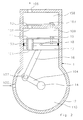
- Fig. 1 is a preferred embodiment of such air suspension system shown.
- the aforementioned compressed air conveying device is shown in the dashed bordered block (1) .
- the air discharge device in combination with the air dryer device, hereinafter called air discharge / - drying device (2), shown.
- the air suction device is shown in the dashed bordered block (4) .
- the aforementioned compressed air reservoir (9) and the bellows (64, 65, 66, 67) are shown.
- the air spring bellows (64, 65, 66, 67) are further associated with displacement sensors (68, 69, 70, 71).
- the displacement sensors (68, 69, 70, 71) provide via electrical lines in each case the level of the vehicle body in the area of that air spring bellows, which they are assigned, representing electrical signal to an electronic control unit (5).
- a reversing valve device which serves to control the direction of compressed air flow when conveying the compressed air between the compressed air reservoir (9) and the air bellows (64, 65, 66, 67).
- the compressed air reservoir (9) can be connected as a compressed air source to the air spring bellows (64, 65, 66, 67) alternately in a first switching position.
- the air spring bellows (64, 65, 66, 67) can be connected as a compressed air source to the compressed air reservoir (9). Accordingly, in the first switching position, the function "increase air quantity" with respect to the air spring bellows (64, 65, 66, 67) is adjustable, in the second switching position the function "lower air quantity” is adjustable.
- the Indian Fig. 1 illustrated compressed air reservoir (9) is connected via a designed as an electromagnetically operable 2/2-way valve shut-off valve (8), hereinafter also called storage valve, connected to a terminal (318) of the changeover valve device (3).
- the air spring bellows (64, 65, 66, 67) are each connected via upstream shut-off valves (60, 61, 62, 63), hereinafter also called bellows valves, and via a common compressed air line (72) to a further connection (316) of the changeover valve device (3 ) connected.
- the bellows valves (60, 61, 62, 63) are preferably also designed as electromagnetically actuated 2/2-way valves.
- check valves (51, 52) connected on the inlet side are provided.
- the check valve (51) is connected on the outlet side to the air intake device (4) and to a suction port (105) of the compressed-air delivery device (1).
- An outlet port (106) of the compressed air conveying device (1) is connected to an air inlet of the air discharge / drying device (2).
- a check valve (50) is arranged at an outlet of the air discharge / - drying device (2).
- the check valves (50, 52) are connected on the outlet side to a further connection (315) of the changeover valve device (3).
- a pressure sensor (7) is arranged on the outlet side of the check valve (50), which detects the pressure present there and emits a pressure representative of this electrical signal to the electronic control unit (5). If necessary, the pressure sensor (7) can be provided as an option or can be dispensed with in order to achieve more favorable production costs of the air suspension system, as will be explained in more detail below.
- an electric motor (6) is provided which can be switched on via an electrical signal from the electronic control unit (5).
- the electric motor (6) drives a piston machine (12) provided in the compressed air delivery device (1) via a drive shaft (14).
- the electronic control unit (5) is used to control all functions of the air suspension system.
- the control unit (5) via electrical lines with an electrical actuator of the switching valve device (3), the shut-off valves (8, 60, 61, 62, 63), the optional pressure sensor (7), the displacement sensors (68, 69, 70, 71) and the electric motor (6).
- the compressed air conveying device (1) has the functional units explained below.
- a piston machine (12) serves to convey air from the suction port (105) to the outlet port (106) of the compressed air delivery device (1).
- the piston engine (12) can be used as a conventional piston compressor, z. B. as Kippkolbenkompressor be designed.
- the piston engine (12), as mentioned, via a drive shaft (14) can be driven.
- On the suction side of the compressed-air conveying device (1) designed as a check valve suction valve (11) is arranged.
- a likewise designed as a check valve outlet valve (13) is arranged. By the check valves (11, 13), the conveying direction of the compressed-air conveying device (1) is determined.
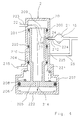
- FIG. 2 An embodiment of such a compressed air conveying device (1) is in the Fig. 2 represented in the form of a reciprocating compressor.
- the aforementioned piston engine (12) has within its housing a drive shaft (14), which is mechanically connected via a connecting rod (104), a joint (107), a connecting rod (16) and via a further joint (18) with a piston (17). Due to a rotation of the drive shaft (14), the piston (17) performs an upward and downward movement.
- the piston (17) is provided with a circumferential seal (100) which seals a pressure chamber (108) provided above the piston with respect to a suction space (110) provided in the crankcase of the compressor (12).
- the suction valve (11) designed constructively as a lamella is arranged, which is attached to the piston (17) via a screw (19).
- the suction valve (11) serves to seal the pressure chamber (108) with respect to a suction opening (101) penetrating the piston (17) during an upward movement of the piston (17).
- an outlet space (150) is provided above the pressure chamber (108).
- the outlet space (150) is designed constructively designed as a lamella exhaust valve (13) which is fastened by means of a screw (103) on the underside of the outlet space (150).
- the outlet valve (13) seals the outlet chamber (150) against an outlet channel (102) and with respect to the pressure chamber (108) during a downward movement of the piston (17).
- Fig. 1 the air discharge / - drying device (2) in an advantageous embodiment, a compressed air controlled 4/3-way valve (20) and an air dryer (21). Between the 4/3-way valve (20) and the air dryer (21), the volume (15) shown with a storage symbol is shown, the volume of the air discharge / - drying device (2) resulting volumes, in particular of the air dryer Cartridge, represented. In addition, in the volume (15) on the outlet side of the compressed-air conveying device (1) existing volumes are summarized.
- the compressed air delivered by the compressed air conveying device (1) flows in the compressed air in the Fig. 1 illustrated switching position of the valve (20) via a compressed air line (22) at a terminal (223) in the valve (20), at a further terminal (224) from the valve (20) in a compressed air line (24), from there through the Air dryer (21) and from there via the check valve (50) to the switching valve device (3).
- the outlet side of the air dryer (21) is additionally returned via a compressed air line (25) to a further connection (225) of the valve (20), which in the illustrated switching position of Fig. 1 is locked.
- Another connection (215) of the valve (20) serves as Ventilation connection of the air suspension system; this is connected to the atmosphere.
- connection (223) of the valve (20) connected to the compressed air delivery device (1) is connected via a compressed air line (23) to a pressure-actuated control connection of the valve (20).
- the valve (20) of the in the Fig. 1 shown switching position can be switched to a second and a third switching position.
- the in the first switching position still provided with a relatively large passage cross-section connecting channel between the terminals (223, 224) of the valve (20) is switched in the second switching position in a throttle position with significantly reduced flow area.
- the compressed air line (25) is still shut off in the second switching position.
- the third switching position is finally taken.
- valve (20) in this context also serves as an overpressure safety valve, ie as a safeguard against undesirably high pressure values in the air suspension system, as will be explained below.
- the air dryer is advantageously arranged such that it is always flowed through in the same flow direction of the compressed air both during normal operation of the air suspension system as well as in the so-called regeneration mode, ie when dehumidifying the dryer granules .
- This has the advantage that the air dryer (21) permanently on the outlet side of the compressed-air conveying device (1), in particular spatially relatively close to the compressed-air conveying device, can be arranged and thereby flows in each mode with preheated by the compressed-air conveying device air can be. Due to the spatially sealed arrangement on the compressed air conveying device, the warmed compressed air with relatively little drop in temperature can reach the air dryer (21). Since warm air can absorb moisture much better than cold air, this embodiment of the invention provides a further significant improvement the efficiency in the regeneration of the dryer granules can be achieved.
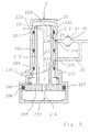
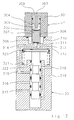
- the valve (20) has a housing (200), which in its lower part of the Fig. 3 shown section has a comparison with its other sections enlarged cross-section.
- the housing (200) can be designed, for example, rotationally symmetrical.
- a valve body (209) is arranged, which is rigidly connected to a piston (205) provided for actuating the valve body (209).
- the piston (205) is guided in the housing portion (207) and sealed by a circumferential seal (206) in the housing portion (207).
- a circumferential seal (206) in the housing portion (207).
- annular seals (201, 202, 204) are disposed in the housing (200) which are held in position by grooves disposed in the housing (200).
- the valve body (209) has a wall (210) which is guided inside the seals (201, 202, 204) and is displaceable due to a movement of the piston (205) relative to the seals (201, 202, 204).
- the housing (200) has openings (223, 224, 225) to which the aforementioned compressed air lines (22, 24, 25) are connected. Furthermore, an opening for the vent connection (215) is provided in the lower region of the housing (200).
- the wall (210) of the valve body (209) has an opening (212) on the side facing the opening (224).
- This opening (212) is dimensioned relatively small in cross section, compared to the other flow areas of the valve (20). In this way, at a compressed air flow through the opening (212), a throttle effect can be achieved, which in the aforementioned second and third switching position of the valve (20) is effective.
- a via the compressed air line (22) fed compressed air stream can in the in the Fig. 3 shown switching position of the valve (20) through the channel (213) in the compressed air line (24) and pass from there through the air dryer (21) to the check valve (50).
- a compressed air flow through the compressed air line (25) is prevented by the seals (202, 204), ie the compressed air line (25) is shut off.
- the compressed air can propagate through an opening (214) penetrating the piston (205) into the space enclosed by the piston (205), the housing bottom (222) and the seal (206) ,
- valve body (209) reaches the seal (201), whereby the in the Fig. 3 shown channel (213) is shut off.
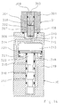
- a compressed air flow from the compressed air line (22) to the compressed air line (24) now takes place through the opening acting as a throttle (212), as indicated by the arrow (216).
- the arrow (23) continues to be a compressed air propagation through the opening (214) in the of the piston (205), the housing bottom (222) and the seal (206) enclosed space.
- the compressed air line (25) is still shut off.
- valve (20) With further increasing pressure in the valve (20) is in the Fig. 5 shown third switching position of the valve (20) taken. In this switching position, the piston (205) bears against the upper side of the housing region (207). A compressed air flow from the compressed air line (22) to the compressed air line (24) continues as in the second switching position throttled through the opening (212), as shown by the arrow (216). The previously closed by the seals (202, 204) and the compressed air line (25) shut-off space is now opposite the seal (204) open so that compressed air from the compressed air line (25) through the opening (215) can flow into the atmosphere, as shown by the arrow (217).
- FIG. 6 an alternative embodiment of the air discharge / drying device (2) is shown.
- a 4/2-way valve is used instead of the previously described 4/3-way valve, ie a simplified executed valve with only two switching positions.
- the valve (20) can be constructed more simply and produced more cheaply.
- the air discharge - / - drying device (2) can also be provided with an electromagnetically actuated valve (20).
- the valve (20) according to Fig. 7 has an electromagnet (27) as an actuating element instead of the pressure medium actuation.
- the electromagnet (27) can be connected via an electrical line (26) to the control unit (5).
- the air discharge / drying device (2) is provided with a pressure-controlled valve device (220) downstream of the air dryer (21).
- the air dryer (21) is also preceded by a throttle (28).
- the valve device (220) is designed as a 3/2-way valve that is connected in the compressed air line connected to the pressure outlet of the air dryer (21) is. This results in a simple guidance of the compressed air lines on the outlet side of the air dryer (21).
- a further embodiment of the air discharge / - drying device (2) is shown, which, as in the Fig. 8 a throttle (28) upstream of the air dryer (21) and a pressure-controlled valve device (29) connected downstream of the air dryer (21).
- the valve device (29) is designed as a 2/2-way valve.
- the air discharge / - drying device (2) is particularly inexpensive to produce.
- the according to Fig. 9 represented additional branch point of the compressed air lines on the outlet side of the air dryer can be advantageously integrated directly into the valve device (29) in a practical realization, so that in relation to the embodiment according to Fig. 8 no increased effort in terms of leadership of the compressed air lines results.
- the throttle (28) is designed such that sufficient for the desired requirements compressed air flow through the throttle (28) is possible.
- the passage cross section of the valve device (29, 220) should be significantly larger than the passage cross section of the throttle (28), eg in the ratio 4: 1.
- Fig. 1 is proposed as reversing valve device (3) precontrolled by compressed air, electromagnetically actuated directional control valve arrangement consisting of a pilot valve (31) and a changeover valve (30).
- the pilot valve (31) is designed as an electromagnetically operated 3/2-way valve, which is actuated by the control unit (5) via an electrical line.
- the switching valve (30) is designed as a pneumatically operated 4/2-way valve which is connected via compressed air connections (315, 316, 317, 318) with the other parts of the air suspension system.
- the compressed air actuatable control input of the changeover valve (30) is connectable via the pilot valve (31) optionally with the of the compressed air conveying means (1) via the air discharge / - drying device (2) and the check valve (50) pressure or with the atmosphere.
- control volume of this valve is to be kept low.
- An embodiment of such a designed switching valve with low control volume is in the Fig. 13 and 14 shown. Furthermore, it is advantageous to minimize the switching frequency by means of suitable control algorithms in the control unit (5) in order to minimize the consumption of air.
- valve assembly (3) with a pilot valve has the advantage that the actuating forces, which must apply the solenoid, turn out lower. This allows the electromagnet smaller and cheaper be interpreted.
- the removal of the pilot pressure from the compressed air output branch of the compressed air conveying device (1) has the advantage that the changeover valve device (3) is functional in any operating condition of the air suspension system, z. B. even at initial startup at still empty compressed air storage (9).
- FIG. 10 an alternative embodiment of the reversing valve device (3) with an electric motor operated, designed as a slide valve switching valve (30) and one of the control unit (5) actuatable for actuation electric motor (32) is shown.
- a further alternative embodiment of the switching valve device (3) is in the Fig. 11 shown.
- switching valve device (3) can with respect to their compressed air connection sides (35, 36) at will in accordance with the air suspension system Fig. 1 to get integrated.
- the connection side (35) with the compressed air conveying device and the connection side (36) are connected to the compressed air reservoir or the air spring bellows.
- FIG. 12 Another embodiment of the switching valve device (3) is in the Fig. 12 specified.
- four pneumatically operable 2/2-way valves (37, 38, 39, 300) are used for switching, which can be actuated by the already explained pilot valve (31).
- the connection sides (35, 36) of the switching valve device (3) can also, as shown in the Fig. 11 explained, optionally in the air suspension system according to Fig. 1 be connected.
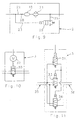
- FIG. 13 Based on Fig. 13 and 14 an advantageous structural design of the in the Fig. 1 illustrated switching valve device (3) are explained.
- the changeover valve device (3) is shown in the unactuated state, in the Fig. 14 in the actuated state.
- the switching valve device (3) consists, as explained, of the pilot valve (31) and the switching valve (30).
- the pilot valve (31) has an electromagnet arrangement (301, 302) which is designed as an electrical coil (301) and an armature (302) arranged inside the coil (301) and movable in the longitudinal direction of the coil (301).
- the armature (302) also serves as a valve closing body.
- the armature (302) has longitudinally extending grooves (307, 308) serving as air ducts.
- the armature (302) rests on a spring (304) disposed within the coil (301).
- the spring (304) in turn is supported on a valve closure piece (309), which closes the pilot valve (31) at its top.
- the valve closure piece (309) is provided with a bore extending along its longitudinal axis, which serves as a pressure outlet channel (303) for venting into the atmosphere from the pilot valve (31) in the switching valve (30) einêtbaren compressed air.
- the pilot valve (31) is connected to the switching valve (30) to a rigid unit.
- the armature (302) is urged by the force of the spring (304) onto a valve seat (311) provided in the change-over valve (30).
- the seal (306) closes the valve seat (311).
- the seal (305) is not in this state on the valve closure piece (309), ie, the pressure outlet channel (303) is opened.
- the change-over valve (30) consists of a valve housing (319) which has various compressed-air connections (314, 316, 317, 318) and ventilation ducts (314, 312).
- the compressed air connection (315) is used for connection to the outlet side of the compressed-air conveying device (1), ie on the basis of the representation of Fig. 1 for connection to the outlet sides of the check valves (50, 52).
- the compressed air connection (317) is used for connection the suction side of the compressed air conveying device (1), ie according to Fig. 1 for connection to the inlet sides of the check valves (51, 52).
- the compressed air connection (318) is used to connect the compressed air reservoir (9) via the storage valve (8).
- the compressed air connection (316) is used to connect the air spring bellows (64, 65, 66, 67) via the bellows valves (60, 61, 62, 63).
- compressed air to be used for precontrol can flow to the pilot valve (31) or to the armature (302).
- the armature (302) against the force of the spring (304) in the in the Fig. 14 shown position moves.
- the valve seat (311) is released, so that compressed air via a chamber (310) and via the compressed air passage (312) in a pilot chamber (313) can flow.
- the pilot chamber (313) is bounded by a longitudinally movable piston (320), which is acted upon by the in the pilot chamber (313) located compressed air.
- the piston (320) is supported by a spring (321) on a counter-stop in the valve housing (319).
- the air suction device (4) As another functional unit is in the Fig. 1 the air suction device (4) is provided. This has an atmosphere connected to the air intake port (42), a filter (41) for filtering out impurities in the ambient air and a check valve (40).
- This type of embodiment of the air intake device (4) has the advantage that with appropriate air requirement on the suction side of the compressed-air conveying device (1), z. B. at too low pressure in the compressed air reservoir (9) or shut-off valves (8, 60, 61, 62, 63) in the case of regeneration of the dryer granules, air is sucked in a sufficient manner automatically from the atmosphere, since the check valve (40) requires no special control.
- the air suspension system is in accordance with Fig. 1 the compressed air reservoir (9) and the Heilfederbälge (64, 65, 66, 67) initially at a pressure level corresponding to the atmospheric pressure.
- a sufficient amount of compressed air for a proper function of the air suspension system is thus not yet available in this state.
- a connection between the outlet port (106) of the compressed-air conveying device (1) and the air spring bellows (64, 65, 66, 67) is connected by means of the changeover valve device (3).
- the compressed air reservoir (9) with the suction side of the compressed air conveying device (1) is connected.
- the storage valve (8) and the bellows valves (60, 61, 62, 63) are switched to the open position. Then, the electric motor (6) is turned on, so that the compressed air conveying means (1) starts to supply compressed air.
- the resulting level position via the displacement sensors (68, 69, 70, 71) is monitored by the control unit (5).
- the control unit (5) switches the bellows valve (60, 61, 62, 63) upstream of this air bellows into the shut-off position.
- the control unit (5) shuts off the electric motor (6) and the storage valve (8) switches to the shut-off position. This completes the filling process of the air spring bellows (64, 65, 66, 67).
- the air spring bellows (64, 65, 66, 67) can be useful when starting up the air suspension system and a filling of the initially at atmospheric pressure compressed air reservoir (9).
- a connection between the outlet port (106) of the compressed air conveying device (1) and the compressed air reservoir (9) is switched by means of the changeover valve device (3).
- the storage valve (8) is switched to the open position, the bellows valves (60, 61, 62, 63) remain in the shut-off position.
- the electric motor (6) is turned on, so that the compressed air conveying means (1) starts to supply compressed air.
- the compressed air conveying device (1) then sucks air from the atmosphere through the air intake device (4).
- the sucked air is discharged to the outlet side of the compressed air conveying device (1) and flows through the air discharge / - drying device (2), the check valve (50), the changeover valve device (3) and the storage valve (8) in the compressed air reservoir (9 ).
- This filling process of the compressed air reservoir (9) can be timed, e.g. the electric motor (6) is turned on for a predetermined refill period. If the pressure sensor (7) is provided, the resulting pressure level is monitored by the control unit (5) via the pressure sensor (7). After the predetermined filling time period or upon reaching a desired pressure value, the control unit (5) switches the electric motor (FIG. 6) again and also switches the storage valve (8) in the shut-off position. This completes the filling process of the compressed air reservoir (9).
- the above-described reduced pressure state z. B. due to leaks in parts of the air suspension system or by operation of the air suspension system under changed climatic conditions, ie at lower ambient temperatures occur.
- the control unit (5) recognizes such a reduced pressure state automatically by regular evaluation of the signals of the sensors (7, 68, 69, 70, 71) and, in such a case, automatically sets the operating mode "reduced pressure compensation".
- the control unit (5) by means of the switching valve device (3) connects the compressed air reservoir (9) with the suction side of the compressed-air conveying device (1).
- the control unit (5) by means of the switching valve device (3) connects the compressed air reservoir (9) with the suction side of the compressed-air conveying device (1).
- the control unit (5) by means of the switching valve device (3) connects the compressed air reservoir (9) with the suction side of the compressed-air conveying device (1).
- the control unit (5) by means of the switching valve device (3) connects the compressed air reservoir (9) with the suction side of the compressed-air conveying device (1).
- the state "overpressure compensation” can be maintained, for example, until the overpressure has reduced so much that the valve (20) automatically returns to its second switching position.
- a regulation and limitation of the overpressure by appropriate coordination between the compressed air actuation of the valve (20) and the return spring (208), in other words, by appropriate choice of the effective area of the piston (205) and the force of the spring (208 ).
- the illustrated air suspension system is thus functional even without the pressure sensor (7).
- z. B. be omitted for cost reasons on this pressure sensor.
- a pressure sensor (7) is provided, there is a further advantage in that even with a defect or failure of the pressure sensor (7), the air suspension system can continue to operate safely.
- An avoidance of unacceptable pressure in the compressed air reservoir (9) can, for. B. in an air suspension system without pressure sensor (7) by connecting the compressed air reservoir (9) with the overpressure safety valve (20) at regular intervals, eg. B. every 30 minutes, be ensured.
- control algorithms can be realized, which can be provided in the control unit (5) as a control program, and can be achieved by the other advantages in the control of the air suspension system.
- the control unit (5) in an advantageous embodiment of the invention performs a regular monitoring of the pressure in the compressed air reservoir (9).
- the control unit (5) connects the compressed air reservoir (9) by actuation of the accumulator valve (8) and the reversing valve device (3) with the pressure sensor (7).
- About the check valves (50, 52) is prevented that the compressed air from the compressed air reservoir (9) undesirably spreads into other branches of the air suspension system. If the control unit (5) determines in such a regular check that the pressure in the compressed air reservoir (9) exceeds a desired limit value, the control unit (5) sets the operating mode "overpressure compensation".
- control unit (5) interrupts the above-described overpressure venting via the valve (20) by switching over the changeover valve device (3) at predetermined time intervals such that in turn a connection is established between the pressure sensor (7) and the compressed air reservoir (9) so that the remaining air pressure in the compressed air reservoir can be measured. If a pressure value is determined which is above a limit value stored in the control unit (5), then the control unit (5) switches over the changeover valve device (3) again so that a further overpressure reduction can take place via the valve (20). Otherwise, the control unit (5) ends the operating state "overpressure compensation" and in turn sets the operating mode "neutral state".
- control unit (5) checks the pressure values present in the air spring bellows (64, 65, 66, 67) at certain intervals by connecting one of the air spring bellows (64, 65, 66, 67) to the pressure sensor (7) suitable Control of the switching valve device (3) and the shut-off valves (8, 60, 61, 62, 63).
- suitable Control of the switching valve device (3) and the shut-off valves (8, 60, 61, 62, 63) are stored in the control unit (5).
- the control unit (5) may be programmed in an advantageous embodiment such that it limits said pressure difference to a predetermined value.
- the control unit (5) switches the air suspension system into the already described operating mode "overpressure compensation", wherein additionally Turning on the electric motor (6) the compressed air conveying device (1) by the control unit (5) is set for a predetermined time in operation. As a result, a certain amount of air is pumped via the valve (20) into the atmosphere. To Expiration of the predetermined time, the control unit (5) switches off the compressed air delivery device (1) and again checks the pressure present in the compressed air reservoir (9).
- the control device (5) switches the air suspension system into the "reduced pressure compensation" operating mode already explained. As a result, air is sucked from the atmosphere via the air intake device (4) and pumped into the compressed air reservoir (9). When a desired pressure value is reached, the control unit (5) switches the air suspension system back to the "Neutral" operating mode.
- the control unit (5) checks based on the signals of the displacement sensors (68, 69, 70, 71), whether the level position of the vehicle body relative to the vehicle wheels or the roadway corresponds to a desired target value.
- This setpoint can be z. B. depending on the driving situation automatically from the control unit (5) can be selected from a number of predetermined setpoints or setpoint functions. It can also be a setpoint by manual intervention z. B. be provided by the driver.
- the control unit (5) then controls the air suspension system in the operating mode "Increase".
- the compressed air reservoir (9) is connected by switching the accumulator valve (8) in the open position with the changeover valve device (3).
- the switching valve device (3) is switched such that the compressed air reservoir (9) is connected to the suction side of the compressed air conveying device (1).
- the outlet side of the compressed-air conveying device (1) with the bellows valves (60, 61, 62, 63) is connected.
- the control unit (5) further switches the bellows valve (60) in the open position.
- the compressed air flows directly through the non-return valve (52) even when the compressed air conveying device (1) is stationary, and additionally into the compressed air conveying device (1)
- Air spring bellows (64) ie by means of the check valve (52), the compressed air conveying device (1) in the manner of a bypass can be bridged.
- the direct connection via the check valve (52) a lesser and thus more favorable flow resistance is achieved.
- the control unit (5) monitors the filling of the air spring bellows (64) on the basis of the pressure signal output by the pressure sensor (7) and the travel signal output by the displacement sensor (68). As soon as the desired setpoint of the level position on the air spring bellows (64) is reached, the control unit switches (5) the storage valve (8) and the bellows valve (60) in the shut-off position.
- the control unit (5) switches on the electric motor (6) to assist the air delivery, whereby the compressed air delivery device (1 ) is put into operation.
- the compressed air delivery device (1 ) is put into operation.
- the pressure in the compressed air reservoir (9) is less than or equal to the pressure in the air spring bellows (64) to be filled, or when the filling of the air spring bellows is to be accelerated.
- the check valve (50) for this purpose as close as possible to the Umschaltventil raised (3) arranged to minimize compensation operations on the compressed air lines.
- the compressed air conveying device (1) Should it happen when conveying the air from the compressed air reservoir (9) by the compressed air conveying device (1) that the amount of compressed air in the compressed air reservoir (9) is not sufficient for filling the exemplified air spring bellows (64), the air pressure would the suction side of the compressed air conveying means (1) fall below the atmospheric pressure, whereby the check valve (40) of the air suction device (4) opens automatically. This allows the compressed air delivery device (1) automatically and without further intervention by the control unit (5) suck the necessary air from the atmosphere and thus provide the required amount of air in the air bag (64).
- the air spring bellows (64) should be vented.
- the control unit (5) controls the air suspension system in the operating mode "lowering".
- the storage valve (8) and the bellows valve (60) are switched to the open position.
- the switching valve device (3) is switched such that the air spring bellows (64) with the suction side of the compressed-air conveying device (1) and the compressed air reservoir (9) with the outlet side of the compressed-air conveying device (1) is connected.
- the control unit (5) monitors the venting of the air spring bellows (64) via the sensors (7, 68). When the desired level position is reached in accordance with the setpoint at the air bag (64), the control unit (5) ends the operating mode "lowering" by the storage valve (8) and the bellows valve (60) are switched to the shut-off position.
- the control unit (5) switches on the electric motor (6) to assist the air delivery, whereby the compressed air delivery device (1 ) is put into operation. This is particularly necessary if the pressure in the air spring bellows (64) to be emptied is less than or at most equal to the pressure in the compressed air reservoir (9), or if the emptying of the bellows is to be accelerated. An intake of air from the atmosphere via the air intake device (4) is not considered in this mode of operation.
- the compressed air delivery device (1) therefore sucks in air from the air spring bellows (64) via the bellows valve (60), the changeover valve device (3) and the check valve (51) and conveys them via the air discharge / drying device (2) Check valve (50), the changeover valve device (3) and the storage valve (8) in the compressed air reservoir (9).
- the valve (20) serving for overpressure protection is activated automatically and switches to its third switching position, so that the compressed air delivery device (1) conveyed compressed air is vented into the atmosphere.
- the control unit (5) can also be checked on reaching a predetermined pressure value stored in the control unit (5) in the compressed air reservoir (9) which is based on the signal of the pressure sensor (7). Prevent further conveying compressed air into the compressed air reservoir (9) by the control unit (5) switches the storage valve (8) in the shut-off position. The henceforth of the compressed air conveying means (1) promoted compressed air is then vented as a result of a rapidly increasing pressure at the opposite the compressed air reservoir (9) shut off outlet side of the compressed-air conveying device (1) via the valve (20) into the atmosphere.
- the check valve (51) for this purpose as close as possible to the changeover valve device (3), to minimize compensation processes via the compressed air lines.
- a typical size for the volume (10) in passenger air suspension systems is about 0.5 liters, for the volume (15) about 0.4 liters.
- the check valves (50, 51) can on a structurally complex volume minimization in the compressed air conveying device (1), often structurally integrated into the compressed air conveying device (1) electric motor (6) and the air discharge - / - drying device (2 ) are waived. Instead, a targeted optimization of the design in terms of cost can be performed.
- the operating mode "regeneration” serves to regenerate, ie to dehumidify, the dryer granulate provided in the air dryer (21).
- the control unit (5) switches the storage valve (8) and the bellows valves (60, 61, 62, 63) in the shut-off position and sets by switching on the electric motor (6), the compressed-air conveying device (1) into operation.
- the compressed air conveying device (1) then sucks in air from the atmosphere via the air suction device (4) and delivers this compressed air on the outlet side, wherein the compressed air is heated to the ambient temperature.
- the valve (20) first switches from the first switching position into the second switching position and finally into the third switching position.
- the compressed air flows from the compressed air line (22) throttled through the valve (20) in the compressed air line (24), that is, the compressed air expands to a lower pressure level than that in the compressed air line (22) existing pressure level.
- the Heilabgabe - / - drying device (2) is preferably arranged spatially relatively close to the compressed air conveying device (1), so that the heated compressed air arrives in the air dryer (21) without significant reduction in temperature.
- the thus relaxed and also heated air has a relatively high moisture absorption potential, so that the compressed air flowing from the air dryer (21) in the compressed air line (25) has a relatively high moisture content.
- This air is then vented through the valve (20) into the environment. As a result, a very efficient and rapid drying of the dryer granules is achieved.
- the regeneration of the dryer granules is also always carried out when the already explained operating mode "overpressure compensation" is executed, d. H. at degradation of z. B. in the compressed air reservoir (9) stored excess compressed air via the valve (20). In this case, it is not necessary to draw in air from the atmosphere.
- the operating mode "regeneration" of the control unit (5) is always carried out automatically following one of the other operating modes, if in this case the compressed air conveying device (1) has been put into operation.
- the control unit (5) performs the operating mode "regeneration" in the sense of a caster, ie at the end of a previous operating mode, eg. B. "increase", the accumulator valve (8) and the bellows valves (60, 61, 62, 63) are switched to the shut-off, the electric motor (6) but not immediately switched off, but left turned on for a follow-up.
- the compressed air conveying device (1) continues to run and builds on the outlet side to an overpressure.
- the pressurized air escapes via the valve (20) and the air dryer (21), so that the described regeneration of the dryer granules is performed.
- the control unit (5) switches off the electric motor (6), whereby the air suspension system from the operating mode "regeneration" in the operating mode "normal state” passes. This ensures that the dryer granules at all times has sufficient moisture absorption capacity.
- the air dryer (21) is always traversed in all operating modes of the air suspension system in the same flow direction of the compressed air.
- This makes it possible to arrange the check valve (50) in the compressed air line between the air discharge - / - drying device (2) and the Umschaltventil sensible (3), such that the check valve (50) is arranged relatively close to the Umschaltventil sensible (3), ie downstream of the air discharge / drying device (2).
- This has the advantage that in the operating mode "Increase" an undesirable lowering of the level position due to a pressure equalization between the volume (15) and the bellows can be particularly effectively avoided.
- an air drying concept in which the air dryer (21) in the regeneration mode in the opposite flow direction of the compressed air is flowed when conveying compressed air by the compressed air conveying device (1), as known from the aforementioned prior art, then would have the check valve (50) in the air suspension system according to Fig. 1 between the compressed air conveying device (1) and the air discharge / - drying device (2) are arranged.
- the check valve (50) could not prevent pressure equalization operations between the volumes present in the air discharge / dryer device (2) and the air spring bellows. The consequence would be that in the operating mode "increase" an undesirable lowering of the level position due to the pressure compensation can occur.
- controller (5) e.g. as a program part in a control program executed in the control unit (5), be provided to switch the air suspension system in the operating mode "regeneration" when a high moisture density is present in the air suspension system.
- an additional humidity sensor for determining the air humidity in the air suspension system can be provided, which emits a signal representing the air humidity to the control unit (5).
- the air suspension system can still be operated in the operating mode "starting assistance".
- This operating mode is always required when the drive power that can be applied by the electric motor (6) does not cause the compressor (12) to start up. This can, for example, at a relatively high back pressure on the outlet side, d. H. in the outlet space (150) of the compressor (12), in particular when the piston (17) is in a position approximately midway between the two dead centers.
- the storage valve (8) is first opened before starting the electric motor (6) and the switching valve device (3) is switched over for a short time, ie in each case operated the two switching positions. This will be a pressure equality between the suction side and the outlet side of the compressed air conveying device (1). Then the electric motor (6) is started.
- control unit (5) recognizes a start-up aid requirement by periodically monitoring the pressure values determined by the pressure sensor (7), or by evaluating the stored pressure values of the compressed air reservoir (9) and the air spring bellows or by monitoring of the electric motor ( 6) absorbed current.
- the control unit (5) connects with recognized start-up assistance by suitable control of the Umschaltventil worn (3) and the shut-off valves (8, 60, 61, 62, 63) either the compressed air reservoir (9) or a bellows with relatively high air pressure with the suction side of Compressed air conveying device (1).
- the piston (17) of the compressor (12) is pressurized from its underside, so that for a start of the compressor (12) required by the electric motor (6) to be fed driving power is reduced. Once the compressor (12) has started, can be switched back to the actual desired operating mode of the air suspension system.
Landscapes
- Engineering & Computer Science (AREA)
- Mechanical Engineering (AREA)
- Vehicle Body Suspensions (AREA)
Description
Die Erfindung betrifft eine Luftfederungsanlage für ein Fahrzeug gemäß dem Oberbegriff des Patentanspruchs 1, insbesondere für ein geschlossenes oder teilgeschlossenes System.The invention relates to an air suspension system for a vehicle according to the preamble of
Eine gattungsgemäße Luftfederungsanlage ist aus der
Bei derartigen Luftfederungsanlagen wird eine Druckluft-Förderungseinrichtung, z.B. ein Kompressor, dazu verwendet, einerseits bei Bedarf Luft von einem Druckluftspeicher in die Luftfederbälge zu pumpen, andererseits bei Bedarf die Luft von den Luftfederbälgen wieder in den Druckluftspeicher zu pumpen. Zum Umschalten zwischen diesen beiden Druckluft-Förderungsrichtungen ist zwischen dem Druckluftspeicher und den Luftfederbälgen auf der einen Seite und der Druckluft-Förderungseinrichtung auf der anderen Seite eine Umschaltventileinrichtung vorgesehen. Bei der eingangs genannten bekannten Luftfederungsanlage sind als Umschaltventileinrichtung beispielsweise zwei elektrisch betätigbare 3/2-Wegeventile vorgesehen, die als direkt gesteuerte Magnetventile ausgeführt sind.In such air suspension systems, a compressed air conveying device, such as a compressor, used to pump on the one hand, if necessary, air from a compressed air reservoir in the bellows, on the other hand, if necessary, to pump the air from the air bellows back into the compressed air reservoir. For switching between these two compressed air conveying directions, a switching valve device is provided between the compressed air reservoir and the air spring bellows on the one side and the compressed air conveying device on the other side. In the known air suspension system mentioned at the outset, for example, two electrically operable 3/2-way valves, which are designed as directly controlled solenoid valves, are provided as a reversing valve device.
Bei einer Luftfederungsanlage ist es erwünscht, daß das Befüllen und Entlüften der Luftfederbälge möglichst schnell erfolgen kann. Dies erfordert Ventileinrichtungen, insbesondere auch eine Umschaltventileinrichtung, mit großer Nennweite, d. h. mit großem Durchlaßquerschnitt. Derartige Ventileinrichtungen bauen relativ groß und sind infolgedessen relativ schwer und teuer.In an air suspension system, it is desirable that the filling and venting of the bellows can be done as quickly as possible. This requires valve devices, in particular also a reversing valve device, with large nominal diameter, d. H. with a large flow area. Such valve devices build relatively large and are therefore relatively heavy and expensive.
Der Erfindung liegt daher die Aufgabe zugrunde, eine Luftfederungsanlage anzugeben, welche eine schnelle Befüllung und Entleerung der Luftfederbälge bei vergleichsweise kostengünstiger und kompakter Bauweise ermöglicht.The invention is therefore based on the object to provide an air suspension system, which allows rapid filling and emptying of the air spring bellows with a relatively inexpensive and compact design.
Diese Aufgabe wird durch die in dem Patentanspruch 1 angegebene Erfindung gelöst. Weiterbildungen und vorteihafte Ausgestaltungen der Erfindung sind in den Unteransprüchen angegeben.This object is solved by the invention defined in
Die Erfindung hat den Vorteil, daß die Umschaltventileinrichtung und damit auch die Luftfederungsanlage leichter und preisgünstiger ausführbar ist als vorbekannte Lösungen. Ein weiterer Vorteil ist, daß nur ein einziger Elektromagnet für die elektrische Betätigung erforderlich ist, der außerdem relativ klein ausgelegt sein kann. Hierdurch wird die elektrische Energieaufnahme bei der Betätigung des Elektromagneten im Vergleich zu vorbekannten Lösungen deutlich verringert. Zudem wird für die Ansteuerung der Umschaltventileinrichtung nur ein einziger Steueranschluß an einem elektronischen Steuergerät benötigt.The invention has the advantage that the switching valve device and thus also the air suspension system is easier and cheaper to implement than previously known solutions. Another advantage is that only a single electromagnet is required for the electrical actuation, which can also be made relatively small. As a result, the electrical energy consumption during actuation of the electromagnet is significantly reduced compared to previously known solutions. In addition, only a single control connection to an electronic control unit is required to control the Umschaltventileinrichtung.
Unter Nennung weiterer Vorteile wird die Erfindung nachfolgend anhand von Ausführungsbeispielen unter Verwendung von Zeichnungen näher erläutert.With reference to further advantages, the invention will be explained in more detail below with reference to embodiments using drawings.
Es zeigen
- Fig. 1
- eine teilgeschlossene Luftfederungsanlage in schematischer Darstellung und
- Fig. 2
- eine Druckluft-Förderungseinrichtung zum Einsatz in der Luftfederungsanlage gemäß
Fig. 1 und - Fig. 3
- ein 4/2-Wege-Umschaltventil in einer ersten Betriebsstellung und
- Fig. 4
- das 4/2-Wege-Umschaltventil in einer zweiten Betriebsstellung und
- Fig. 5
- das 4/2-Wegeventil in einer dritten Betriebsstellung und
- Fig. 6 bis 9
- weitere Ausführungsformen einer Luftabgabe-/Trocknereinrichtung zum Einsatz in der Luftfederungsanlage gemäß
Fig. 1 und - Fig. 10 bis 12
- weitere Ausführungsformen einer Umschaltventileinrichtung zum Einsatz in der Luftfederungsanlage gemäß
Fig. 1 und - Fig. 13 und 14
- eine 4/2-Wege-Umschaltventileinrichtung in unterschiedlichen Schaltstellungen.
- Fig. 1
- a partially closed air suspension system in a schematic representation and
- Fig. 2
- a compressed air conveying device for use in the air suspension system according to
Fig. 1 and - Fig. 3
- a 4/2-way switching valve in a first operating position and
- Fig. 4
- the 4/2-way switching valve in a second operating position and
- Fig. 5
- the 4/2-way valve in a third operating position and
- Fig. 6 to 9
- Further embodiments of an air discharge / drying device for use in the air suspension system according to
Fig. 1 and - 10 to 12
- Further embodiments of a switching valve device for use in the air suspension system according to
Fig. 1 and - FIGS. 13 and 14
- a 4/2-way switching valve device in different switching positions.
In den Figuren werden für einander entsprechende Teile gleiche Bezugszeichen verwendet.In the figures, like reference numerals are used for corresponding parts.
Eine Luftfederungsanlage für ein Fahrzeug hat die Aufgabe, über Niveauverstellmittel die Niveaulage des Fahrzeugaufbaus gegenüber den Fahrzeugachsen und damit indirekt gegenüber der Fahrbahn einzustellen und zu regeln. Hierfür ist vorzugsweise an jedem Rad eines Fahrzeugs ein derartiges Niveauverstellmittel angeordnet, wobei als Niveauverstellmittel bevorzugt Luftfederbälge eingesetzt werden. Durch Befüllung oder Entlüftung der einzelnen Luftfederbälge können innerhalb eines dafür vorgesehenen Einstellbereichs beliebige Niveaulagen des Fahrzeugaufbaus eingestellt werden. Derartige Luftfederungsanlagen werden bevorzugt mit Druckluft als Druckmedium betrieben.An air suspension system for a vehicle has the task over level adjustment the level position of the vehicle body relative to the vehicle axles and thus indirectly set and regulate the road. For this purpose, such a level adjustment means is preferably arranged on each wheel of a vehicle, wherein air suspension bellows are preferably used as the level adjustment means. By filling or venting of the individual bellows any level positions of the vehicle body can be adjusted within a designated adjustment range. Such air suspension systems are preferably operated with compressed air as the pressure medium.
Unter einem offenen System versteht man bei Luftfederungsanlagen ein System, bei dem die Druckluft bei Bedarf aus der Umgebung, d. h. aus der Atmosphäre, angesaugt wird und in die Luftfederbälge oder in einen Druckluftspeicher, d.h. einen Vorratsbehälter, gepumpt wird. Der Druckluftspeicher ist jedoch nicht unbedingt erforderlich und wird je nach Anforderung auch fortgelassen. Bei einer Entlüftung der Luftfederbälge wird die Druckluft immer direkt in die Atmosphäre abgegeben. Ein Rückfordern der Druckluft von den Luftfederbälgen in den Druckluftspeicher ist dabei nicht vorgesehen. Das offene System ist vergleichsweise einfach aufgebaut und kommt mit relativ wenigen Bauteilen aus. Derartige Luftfederungsanlagen sind seit geraumer Zeit in Nutzfahrzeugen wie Lastkraftwagen und Omnibussen und auch in Personenkraftwagen im Einsatz.Under an open system is understood in air suspension systems, a system in which the compressed air is sucked when needed from the environment, ie from the atmosphere, and in the bellows or in a compressed air reservoir, ie a reservoir, is pumped. However, the compressed air storage is not absolutely necessary and is also omitted depending on the requirement. When venting the air bags, the compressed air is always discharged directly into the atmosphere. A reclaiming the compressed air from the bellows into the compressed air reservoir is not provided. The open system is comparatively simple and has relatively few components. Such air suspension systems have been in commercial vehicles for some time such as trucks and buses and also in passenger cars in use.
Ein geschlossenes System dagegen enthält immer einen Druckluftspeicher, der - zumindest theoretisch - einmalig mit Druckluft befüllt wird, etwa bei der Herstellung der Luftfederungsanlage. Das geschlossene System hat - zumindest theoretisch - keinerlei Verbindung zur Atmosphäre. Im bestimmungsgemäßen Betrieb wird die Druckluft durch eine Druckluft-Förderungseinrichtung nach Bedarf von dem Druckluftspeicher in die Luftfederbälge bzw. von den Luftfederbälgen in den Druckluftspeicher hin- und hergefördert. Dies hat gegenüber einem offenen System den Vorteil, daß die von der Druckluft-Förderungseinrichtung, z.B. einem Kompressor, zu erbringende Änderung des Druckniveaus bei der Luftförderung in der Regel geringer ausfällt, da sich der Druck der zu fördernden Druckluft in der Regel auf einem gewissen, gegenüber der Atmosphäre relativ hohen Niveau befindet. Hierdurch ist der Energieverbrauch eines solchen Systems geringer. Zudem kann die Druckluft-Förderungseinrichtung auf die geringere Leistungsaufnahme hin ausgelegt werden. Vorteilhaft ist außerdem, daß die Druckluft-Förderungseinrichtung mit einer kürzeren Einschaltdauer betrieben werden kann und einer vergleichsweise geringeren Eigenerwärmung unterliegt.A closed system on the other hand always contains a compressed air reservoir, which - at least theoretically - is filled once with compressed air, for example in the production of the air suspension system. The closed system has - at least theoretically - no connection to the atmosphere. In normal operation, the compressed air is conveyed by a compressed air conveying device as needed from the compressed air reservoir in the air spring bellows or from the air spring bellows in the compressed air reservoir back and forth. This has the advantage over an open system that the air-conveying device, e.g. a compressor, to be provided change in the pressure level in the air promotion usually turns out lower, since the pressure of the compressed air to be delivered is usually at a certain, relative to the atmosphere is relatively high level. As a result, the energy consumption of such a system is lower. In addition, the compressed air conveying device can be designed for the lower power consumption. It is also advantageous that the compressed air conveying device can be operated with a shorter duty cycle and subject to a relatively lower self-heating.
Da derartige geschlossene Systeme in der Praxis infolge von Druckluftverlust, z. B. wegen Undichtigkeiten an den aus elastischem Material hergestellten Luftfederbälgen, nicht dauerhaft funktionsfähig wären, gibt es den Vorschlag, sogenannte teilgeschlossene Systeme zu verwenden, bei denen ebenfalls ein Druckluftspeicher vorgesehen ist und bei denen, solange genügend Druckluft in dem System vorhanden ist, die Druckluft wie in dem geschlossenen System zwischen dem Druckluftspeicher und den Luftfederbälgen hin- und hergefördert wird. Zusätzlich ist eine Verbindung zur Atmosphäre vorgesehen, welche zur Auffüllung des Systems mit Druckluft z. B. bei Druckverlusten oder starken Temperaturschwankungen dient und eine Luftansaugung aus der Atmosphäre erlaubt. Zur Vermeidung von Überdruck-Zuständen ist zusätzlich üblicherweise auch eine Luftabgabevorrichtung zur Entlüftung von Überdruck in die Atmosphäre vorgesehen.Since such closed systems in practice as a result of compressed air loss, z. B. due to leaks in the air spring bellows made of elastic material, would not be permanently functional, there is the proposal, so-called partially closed systems use, in which also a compressed air reservoir is provided and in which, as long as enough compressed air is present in the system, the compressed air is conveyed back and forth as in the closed system between the compressed air reservoir and the bellows. In addition, a connection to the atmosphere is provided, which for filling the system with compressed air z. B. is used for pressure losses or high temperature fluctuations and allows an air intake from the atmosphere. In addition, in order to avoid overpressure conditions, an air release device is also usually provided for venting overpressure into the atmosphere.
In einem solchen teilgeschlossenen System findet demnach ein gewisser, wenn auch begrenzter, Luftaustausch mit der Atmosphäre statt. Hierdurch ist das teilgeschlossene System einerseits praxistauglich, kann aber andererseits auch die Vorteile eines geschlossenen Systems zu einem großen Teil nutzen. Eine derartige als teilgeschlossenes System ausgebildete Luftfederungsanlage weist bevorzugt die folgenden funktionellen Einheiten auf:
- Eine Druckluft-Förderungseinrichtung, die vorzugsweise als Kompressor ausgebildet ist und beispielsweise über einen Elektromotor angetrieben werden kann,
- einen Druckluftspeicher zur Speicherung von Druckluft auf einem bestimmten Druckniveau,
- die erwähnten Luftfederbälge,
- eine Luftansaugeinrichtung,
- eine Luftabgabeeinrichtung sowie
- eine Lufttrocknereinrichtung.
- A compressed air conveying device, which is preferably designed as a compressor and can be driven, for example, by an electric motor,
- a compressed air reservoir for storing compressed air at a certain pressure level,
- the mentioned bellows,
- an air intake device,
- an air discharge device as well
- an air dryer device.
Die vorgenannten funktionellen Einheiten sind über betätigbare Ventileinrichtungen, insbesondere elektrisch betätigbare Ventileinrichtungen, derart miteinander verbindbar, daß bezüglich der Luftfederbälge die Funktionen "Luftmenge erhöhen", "Luftmenge halten" sowie "Luftmenge absenken" einstellbar sind. Über die Dauer eines "Luftmenge erhöhen"- bzw. "Luftmenge absenken"-Vorgangs kann dann eine gewünschte Niveaulage eingestellt werden. Gesteuert wird eine derartige Luftfederungsanlage vorzugsweise von einem elektronischen Steuergerät.The abovementioned functional units can be connected to one another via actuatable valve devices, in particular electrically actuated valve devices, such that the functions "increase air quantity", "maintain air volume" and "decrease air volume" can be set with respect to the air spring bellows. A desired level position can then be set via the duration of a "increase air volume" or "lower air volume" process. Such air suspension system is preferably controlled by an electronic control unit.
In der
In dem gestrichelt umrandeten Block (1) ist die zuvor erwähnte Druckluft-Förderungseinrichtung dargestellt. In dem gestrichelt umrandeten Block (2) ist die Luftabgabeeinrichtung in Kombination mit der Lufttrocknereinrichtung, nachfolgend Luftabgabe-/-trocknereinrichtung (2) genannt, dargestellt. In dem gestrichelt umrandeten Block (4) ist die Luftansaugeinrichtung dargestellt. Des weiteren sind der erwähnte Druckluftspeicher (9) sowie die Luftfederbälge (64, 65, 66, 67) dargestellt. Den Luftfederbälgen (64, 65, 66, 67) sind des weiteren Wegsensoren (68, 69, 70, 71) zugeordnet. Die Wegsensoren (68, 69, 70, 71) geben über elektrische Leitungen jeweils ein die Niveaulage des Fahrzeugaufbaus im Bereich desjenigen Luftfederbalgs, dem sie zugeordnet sind, repräsentierendes elektrisches Signal an ein elektronisches Steuergerät (5) ab.In the dashed bordered block (1) the aforementioned compressed air conveying device is shown. In the dashed bordered block (2), the air discharge device in combination with the air dryer device, hereinafter called air discharge / - drying device (2), shown. In the dashed bordered block (4) the air suction device is shown. Furthermore, the aforementioned compressed air reservoir (9) and the bellows (64, 65, 66, 67) are shown. The air spring bellows (64, 65, 66, 67) are further associated with displacement sensors (68, 69, 70, 71). The displacement sensors (68, 69, 70, 71) provide via electrical lines in each case the level of the vehicle body in the area of that air spring bellows, which they are assigned, representing electrical signal to an electronic control unit (5).
In einem weiteren gestrichelt umrandeten Block (3) ist eine Umschaltventileinrichtung dargestellt, die zur Steuerung der Druckluftströmungsrichtung beim Hin- und Herfördern der Druckluft zwischen dem Druckluftspeicher (9) und den Luftfederbälgen (64, 65, 66, 67) dient. Mittels der Umschaltventileinrichtung (3) kann wechselweise in einer ersten Schaltstellung der Druckluftspeicher (9) als Druckluftquelle mit den Luftfederbälgen (64, 65, 66, 67) verbunden werden. In einer zweiten Schaltstellung der Umschaltventileinrichtung (3) können die Luftfederbälge (64, 65, 66, 67) als Druckluftquelle mit dem Druckluftspeicher (9) verbunden werden. In der ersten Schaltstellung ist demnach die Funktion "Luftmenge erhöhen" bezüglich der Luftfederbälge (64, 65, 66, 67) einstellbar, in der zweiten Schaltstellung ist die Funktion "Luftmenge absenken" einstellbar.In another block (3), which is surrounded by a dashed line, a reversing valve device is shown which serves to control the direction of compressed air flow when conveying the compressed air between the compressed air reservoir (9) and the air bellows (64, 65, 66, 67). By means of the reversing valve device (3), the compressed air reservoir (9) can be connected as a compressed air source to the air spring bellows (64, 65, 66, 67) alternately in a first switching position. In a second switching position of the changeover valve device (3), the air spring bellows (64, 65, 66, 67) can be connected as a compressed air source to the compressed air reservoir (9). Accordingly, in the first switching position, the function "increase air quantity" with respect to the air spring bellows (64, 65, 66, 67) is adjustable, in the second switching position the function "lower air quantity" is adjustable.
Der in der
In der in der
Weiterhin ist ein Elektromotor (6) vorgesehen, welcher über ein elektrisches Signal von dem elektronischen Steuergerät (5) einschaltbar ist. Der Elektromotor (6) treibt eine in der Druckluft-Förderungseinrichtung (1) vorgesehene Kolbenmaschine (12) über eine Antriebswelle (14) an.Furthermore, an electric motor (6) is provided which can be switched on via an electrical signal from the electronic control unit (5). The electric motor (6) drives a piston machine (12) provided in the compressed air delivery device (1) via a drive shaft (14).
Das elektronische Steuergerät (5) dient zur Steuerung sämtlicher Funktionen der Luftfederungsanlage. Hierfür ist das Steuergerät (5) über elektrische Leitungen mit einer elektrischen Betätigungseinrichtung der Umschaltventileinrichtung (3), den Absperrventilen (8, 60, 61, 62, 63), dem optionalen Drucksensor (7), den Wegsensoren (68, 69, 70, 71) und dem Elektromotor (6) verbunden.The electronic control unit (5) is used to control all functions of the air suspension system. For this purpose, the control unit (5) via electrical lines with an electrical actuator of the switching valve device (3), the shut-off valves (8, 60, 61, 62, 63), the optional pressure sensor (7), the displacement sensors (68, 69, 70, 71) and the electric motor (6).
Die Druckluft-Förderungseinrichtung (1) weist die nachfolgend erläuterten funktionellen Einheiten auf. Eine Kolbenmaschine (12) dient zum Fördern von Luft von dem Sauganschluß (105) zu dem Auslaßanschluß (106) der Druckluft-Förderungseinrichtung (1). Die Kolbenmaschine (12) kann als herkömmlicher Kolbenkompressor, z. B. auch als Kippkolbenkompressor, ausgelegt sein. Die Kolbenmaschine (12) ist, wie erwähnt, über eine Antriebswelle (14) antreibbar. Auf der Ansaugseite der Druckluft-Förderungseinrichtung (1) ist ein als Rückschlagventil ausgebildetes Saugventil (11) angeordnet. Auf der Auslaßseite der Druckluft-Förderungseinrichtung (1) ist ein ebenfalls als Rückschlagventil ausgebildetes Auslaßventil (13) angeordnet. Durch die Rückschlagventile (11, 13) wird die Förderungsrichtung der Druckluft-Förderungseinrichtung (1) bestimmt.The compressed air conveying device (1) has the functional units explained below. A piston machine (12) serves to convey air from the suction port (105) to the outlet port (106) of the compressed air delivery device (1). The piston engine (12) can be used as a conventional piston compressor, z. B. as Kippkolbenkompressor be designed. The piston engine (12), as mentioned, via a drive shaft (14) can be driven. On the suction side of the compressed-air conveying device (1) designed as a check valve suction valve (11) is arranged. On the outlet side of the compressed-air conveying device (1), a likewise designed as a check valve outlet valve (13) is arranged. By the check valves (11, 13), the conveying direction of the compressed-air conveying device (1) is determined.
Als der Ansaugseite der Druckluft-Förderungseinrichtung (1) zugeordnet werden nachfolgend neben dem bereits erwähnten Saugventil (11) alle mit dem Sauganschluß (105) direkt oder indirekt pneumatisch verbundenen Teile der Luftfederungsanlage, von dem Saugventil (11) bis zu dem Anschluß (317) der Umschaltventileinrichtung (3), betrachtet. Im Ausführungsbeispiel gemäß
Ein auf der Ansaugseite der Druckluft-Förderungseinrichtung (1) mit einem Speicher-Symbol dargestelltes Volumen (10) symbolisiert in der Darstellung die
Ein Ausführungsbeispiel für eine derartige Druckluft-Förderungseinrichtung (1) ist in der
Oberhalb des Druckraums (108) ist ein Auslaßraum (150) vorgesehen. In dem Auslaßraum (150) ist das konstruktiv als Lamelle ausgeführte Auslaßventil (13) vorgesehen, das mittels einer Schraube (103) an der Unterseite des Auslaßraums (150) befestigt ist. Das Auslaßventil (13) dichtet den Auslaßraum (150) gegenüber einem Auslaßkanal (102) sowie gegenüber dem Druckraum (108) bei einer Abwärtsbewegung des Kolbens (17) ab.Above the pressure chamber (108) an outlet space (150) is provided. In the outlet space (150) is designed constructively designed as a lamella exhaust valve (13) which is fastened by means of a screw (103) on the underside of the outlet space (150). The outlet valve (13) seals the outlet chamber (150) against an outlet channel (102) and with respect to the pressure chamber (108) during a downward movement of the piston (17).
Die über den Sauganschluß (105) angesaugte Luft strömt bei einem Abwärtshub des Kolbens (17) durch den Ansaugkanal (101) über das dann geöffnete Ventil (11) in den Druckraum (108), der dann über das Ventil (13) von dem Auslaßraum (150) abgesperrt ist. Bei einem Aufwärtshub des Kolbens (17) schließt das Saugventil (11), wodurch die in dem Druckraum (108) befindliche Luft durch den Auslaßkanal (102) über das dann geöffnete Auslaßventil (13) in den Auslaßraum (150) gepreßt wird. Aus dem Auslaßraum (150) kann die dort befindliche Druckluft dann über den Auslaßanschluß (106) in die nachgeschaltete Luftabgabe-/-trocknereinrichtung (2) strömen.The suctioned via the suction port (105) air flows in a downward stroke of the piston (17) through the intake passage (101) via the then opened valve (11) in the pressure chamber (108), which then via the valve (13) from the outlet space (150) is locked. In an upward stroke of the piston (17) closes the suction valve (11), whereby the air in the pressure chamber (108) is forced through the outlet channel (102) via the then opened outlet valve (13) into the outlet chamber (150). From the outlet space (150), the compressed air located there can then flow via the outlet connection (106) into the downstream air discharge / drying device (2).
Gemäß
Die von der Druckluft-Förderungseinrichtung (1) abgegebene Druckluft strömt in der in der
Der mit der Druckluft-Förderungseinrichtung (1) verbundene Anschluß (223) des Ventils (20) ist über eine Druckluftleitung (23) mit einem druckluftbetätigten Steueranschluß des Ventils (20) verbunden. Bei entsprechend ansteigendem Druck an dem Steueranschluß kann das Ventil (20) von der in der
Durch die Drosselwirkung des Ventils (20) in der zweiten und der dritten Schaltstellung entspannt sich die Druckluft auf ihrem Weg von der Druckluftleitung (22) zu der Druckluftleitung (24), kommt demzufolge entspannt, d. h. auf geringerem Druckniveau, in dem Lufttrockner (21) an und kann dann bei Erreichen der dritten Schaltstellung des Ventils (20) in die Atmosphäre entlassen werden. Durch das Entspannen der Druckluft infolge der Drosselwirkung wird eine verbesserte Regenerationswirkung des in dem Lufttrockner (21) befindlichen Trockner-Granulates erreicht, d. h. es wird mit relativ wenig Druckluftverbrauch eine relativ hohe Trocknungswirkung erzielt.Due to the throttle effect of the valve (20) in the second and the third switching position, the relaxed Compressed air on its way from the compressed air line (22) to the compressed air line (24), thus comes relaxed, ie at a lower pressure level in the air dryer (21) and then on reaching the third switching position of the valve (20) released into the atmosphere become. By relaxing the compressed air as a result of the throttling action, an improved regeneration effect of the dryer granules located in the air dryer (21) is achieved, ie a relatively high drying effect is achieved with relatively little compressed air consumption.
Im Gegensatz zu bekannten Luftfederungsanlagen ist bei der hier beschriebenen Luftfederungsanlage die Lufttrocknereinrichtung in vorteilhafter Weise derart angeordnet, daß sie sowohl im normalen Betrieb der Luftfederungsanlage als auch im sogenannten Regenerationsbetrieb, d. h. beim Entfeuchten des Trockner-Granulates, immer in derselben Strömungsrichtung von der Druckluft durchströmt wird. Dies hat den Vorteil, daß der Lufttrockner (21) permanent an der Auslaßseite der Druckluft-Förderungseinrichtung (1), insbesondere räumlich relativ dicht an der Druckluft-Förderungseinrichtung, angeordnet werden kann und hierdurch in jeder Betriebsart mit von der Druckluft-Förderungseinrichtung vorgewärmter Luft durchströmt werden kann. Durch die räumlich dichte Anordnung an der Druckluft-Förderungseinrichtung kann die angewärmte Druckluft mit relativ wenig Temperaturabfall den Lufttrockner (21) erreichen. Da warme Luft die Feuchtigkeit wesentlich besser aufnehmen kann als kalte Luft, kann durch diese Ausgestaltung der Erfindung eine weitere wesentliche Verbesserung des Wirkungsgrades bei der Regeneration des Trockner-Granulates erreicht werden.In contrast to known air suspension systems in the air suspension system described here, the air dryer is advantageously arranged such that it is always flowed through in the same flow direction of the compressed air both during normal operation of the air suspension system as well as in the so-called regeneration mode, ie when dehumidifying the dryer granules , This has the advantage that the air dryer (21) permanently on the outlet side of the compressed-air conveying device (1), in particular spatially relatively close to the compressed-air conveying device, can be arranged and thereby flows in each mode with preheated by the compressed-air conveying device air can be. Due to the spatially sealed arrangement on the compressed air conveying device, the warmed compressed air with relatively little drop in temperature can reach the air dryer (21). Since warm air can absorb moisture much better than cold air, this embodiment of the invention provides a further significant improvement the efficiency in the regeneration of the dryer granules can be achieved.
In der
In gewissen Abständen sind in dem Gehäuse (200) ringförmige Dichtungen (201, 202, 204) angeordnet, die durch in dem Gehäuse (200) angeordnete Nuten in ihrer Position gehalten werden. Der Ventilkörper (209) weist eine Wandung (210) auf, die innerhalb der Dichtungen (201, 202, 204) geführt ist und infolge einer Bewegung des Kolbens (205) gegenüber den Dichtungen (201, 202, 204) verschiebbar ist. Das Gehäuse (200) weist Öffnungen (223, 224, 225) auf, an die die zuvor erwähnten Druckluftleitungen (22, 24, 25) angeschlossen sind. Des weiteren ist im unteren Bereich des Gehäuses (200) eine Öffnung für den Entlüftungsanschluß (215) vorgesehen.At intervals, annular seals (201, 202, 204) are disposed in the housing (200) which are held in position by grooves disposed in the housing (200). The valve body (209) has a wall (210) which is guided inside the seals (201, 202, 204) and is displaceable due to a movement of the piston (205) relative to the seals (201, 202, 204). The housing (200) has openings (223, 224, 225) to which the aforementioned compressed air lines (22, 24, 25) are connected. Furthermore, an opening for the vent connection (215) is provided in the lower region of the housing (200).
Die Wandung (210) des Ventilkörpers (209) weist auf der der Öffnung (224) zugewandten Seite eine Öffnung (212) auf. Diese Öffnung (212) ist in ihrem Querschnitt relativ klein bemessen, verglichen mit den übrigen Durchflußquerschnitten des Ventils (20). Hierdurch kann bei einem Druckluft-Durchfluß durch die Öffnung (212) eine Drosselwirkung erzielt werden, die in der erwähnten zweiten und dritten Schaltstellung des Ventils (20) wirksam wird.The wall (210) of the valve body (209) has an opening (212) on the side facing the opening (224). This opening (212) is dimensioned relatively small in cross section, compared to the other flow areas of the valve (20). In this way, at a compressed air flow through the opening (212), a throttle effect can be achieved, which in the aforementioned second and third switching position of the valve (20) is effective.
Ein über die Druckluftleitung (22) eingespeister Druckluftstrom kann in der in der
Sobald der über die Druckluftleitung (22) in das Ventil (20) eingespeiste Druck einen gewissen Mindestwert überschreitet, der unter anderem auch von der Reibung zwischen dem Ventilkörper (209) und den Dichtungen (201, 202, 204) abhängt, beginnt der Kolben (205), sich entgegen der Kraft der Feder (208) vom Gehäuseboden (222) wegzubewegen. Ein derartiger Zustand ist in der
In dieser zweiten Schaltstellung erreicht der Ventilkörper (209) die Dichtung (201), wodurch der in der
Bei weiter ansteigendem Druck in dem Ventil (20) wird die in der
In der
In einer weiteren Ausführungsform, die in der
In einer weiteren Ausgestaltung gemäß
In der
Für eine schnelle Druckluftförderung zu den Luftfederbälgen bzw. von den Luftfederbälgen ist die Drossel (28) derart auszulegen, daß eine für die gewünschten Anforderungen ausreichende Druckluftströmung durch die Drossel (28) möglich ist. Um hingegen bei geöffneter Ventileinrichtung (29) eine gute Regenerationswirkung des Trockner-Granulates zu erreichen, sollte der Durchlaßquerschnitt der Ventileinrichtung (29, 220) deutlich größer sein als der Durchlaßquerschnitt der Drossel (28), z.B. im Verhältnis 4:1.For fast compressed air delivery to the air spring bellows or from the air spring bellows, the throttle (28) is designed such that sufficient for the desired requirements compressed air flow through the throttle (28) is possible. In contrast, in order to achieve a good regeneration effect of the dryer granules when the valve device (29) is opened, the passage cross section of the valve device (29, 220) should be significantly larger than the passage cross section of the throttle (28), eg in the ratio 4: 1.
Gemäß
Gegenüber einem direkt durch einen Elektromagneten gesteuerten 4/2-Wege-Umschaltventil hat die in der
In der
Eine weitere alternative Ausführungsform der Umschaltventileinrichtung (3) ist in der
Eine weitere Ausführungsform der Umschaltventileinrichtung (3) ist in der
Anhand der
Die Umschaltventileinrichtung (3) besteht, wie erläutert, aus dem Vorsteuerventil (31) und dem Umschaltventil (30). Das Vorsteuerventil (31) weist eine Elektromagnetanordnung (301, 302) auf, die als elektrische Spule (301) und ein innerhalb der Spule (301) angeordneter, in Längsrichtung der Spule (301) beweglicher Anker (302) ausgebildet ist. Der Anker (302) dient zugleich als Ventilschließkörper. Für den Verwendungszweck als Ventilschließkörper ist der Anker an seiner einen Stirnseite mit einer aus einem Elastomer bestehenden Dichtung (305) und an seiner entgegengesetzten Stirnseite mit einer weiteren ebenfalls aus einem Elastomer bestehenden Dichtung (306) versehen. An seinem Umfang weist der Anker (302) in Längsrichtung verlaufende Nuten (307, 308) auf, die als Luftführungskanäle dienen. Der Anker (302) stützt sich auf einer Feder (304) ab, die innerhalb der Spule (301) angeordnet ist. Die Feder (304) stützt sich wiederum auf einem Ventilverschlußstück (309) ab, welches das Vorsteuerventil (31) an seiner Oberseite abschließt. Das Ventilverschlußstück (309) ist mit einer entlang seiner Längsachse verlaufenden Bohrung versehen, welche als Druckauslaßkanal (303) zur Entlüftung der von dem Vorsteuerventil (31) in das Umschaltventil (30) einsteuerbaren Druckluft in die Atmosphäre dient.The switching valve device (3) consists, as explained, of the pilot valve (31) and the switching valve (30). The pilot valve (31) has an electromagnet arrangement (301, 302) which is designed as an electrical coil (301) and an armature (302) arranged inside the coil (301) and movable in the longitudinal direction of the coil (301). The armature (302) also serves as a valve closing body. For the intended use as a valve closing body of the armature at its one end face with a seal consisting of an elastomer (305) and at its opposite end face with another also made of an elastomer existing seal (306) provided. At its periphery, the armature (302) has longitudinally extending grooves (307, 308) serving as air ducts. The armature (302) rests on a spring (304) disposed within the coil (301). The spring (304) in turn is supported on a valve closure piece (309), which closes the pilot valve (31) at its top. The valve closure piece (309) is provided with a bore extending along its longitudinal axis, which serves as a pressure outlet channel (303) for venting into the atmosphere from the pilot valve (31) in the switching valve (30) einsteuerbaren compressed air.
Das Vorsteuerventil (31) ist mit dem Umschaltventil (30) zu einer starren Einheit verbunden. In dem unbetätigten Zustand, wie in
Das Umschaltventil (30) besteht aus einem Ventilgehäuse (319), der verschiedene Druckluftanschlüsse (314, 316, 317, 318) sowie Lüftführungskanäle (314, 312) aufweist. Der Druckluftanschluß (315) dient zum Anschluß an die Auslaßseite der Druckluft-Förderungseinrichtung (1), d. h. bei Zugrundelegung der Darstellung der
Über den Druckluftkanal (314) kann zur Vorsteuerung zu verwendende Druckluft zu dem Vorsteuerventil (31) bzw. zum Anker (302) strömen. Bei einer Betätigung des Vorsteuerventils (31) durch Anlegen vom elektrischem Strom wird der Anker (302) entgegen der Kraft der Feder (304) in die in der
Über den Ventilschieber (322) werden die Verbindungen zwischen den Druckluftanschlüssen (315, 316, 317, 318) in der anhand der
Als weitere Funktionseinheit ist in der
Die zuvor hinsichtlich ihres Aufbaus beschriebene Luftfederungsanlage kann in einer Reihe von Betriebsmodi betrieben werden, die nachfolgend erläutert werden sollen. Hierbei ergeben sich bei der in der
Folgende Betriebsmodi der Luftfederungsanlage werden nachfolgend unterschieden:
- 1. "Neutralzustand": Hiermit ist ein Grundzustand der Luftfederungsanlage bezeichnet, in welchem keine Druckluftförderung oder Druckluftbewegung zwischen den einzelnen Komponenten der Luftfederungsanlage durchgeführt wird. Dieser Zustand wird insbesondere bei den in der
Fig. 1 angegebenen Schaltstellungen der Ventile sowie bei ausgeschaltetem Elektromotor (6) eingenommen . - 2. "Erhöhen": Hiermit ist ein Erhöhen der Druckluftmenge in einem oder mehreren Luftfederbälgen (64, 65, 66, 67) bezeichnet.
- 3."Absenken": Hiermit ist ein Absenken der Druckluftmenge in einem oder mehreren Luftfederbälgen (64, 65, 66, 67) bezeichnet.
- 4. "Minderdruckkompensation": Hiermit ist eine Kompensation von zu geringem Luftdruck bzw. einer zu geringen Druckluftmenge, z. B. in dem Druckluftspeicher (9), durch Ansaugung von Luft aus der Atmosphäre bezeichnet.
- 5. "Überdruckkompensation": Hiermit ist eine Kompensation von zu hohem Luftdruck bzw. einer zu großen Druckluftmenge in der Luftfederungsanlage, z. B. in dem Druckluftspeicher (9), durch Entlüftung in die Atmosphäre bezeichnet.
- 6. "Regeneration": Hiermit ist eine Regeneration des Lufttrockners (21) bezeichnet, d. h. das Entfernen von in dem Trockner-Granulat des Lufttrockners (21) gespeicherter Feuchtigkeit durch Entlüftung von in der Luftfederungsanlage gespeicherter oder aus der Atmosphäre angesaugter Luft durch den Lufttrockners (21) in die Atmosphäre.
- 7. "Anlaufhilfe": Hiermit ist eine Unterstützung des Anlaufens der Druckluft-Förderungseinrichtung (1) bzw. dessen als Antrieb verwendeten Elektromotors (6) durch Druckluftunterstützung bezeichnet.
- 1. "Neutral state": This is a basic state of the air suspension system referred to, in which no compressed air delivery or compressed air movement between the individual components of the air suspension system is performed. This condition is especially at the in the
Fig. 1 specified switching positions of the valves and when the electric motor (6) is taken. - 2. "Increase": This is an increase in the amount of compressed air in one or more bellows (64, 65, 66, 67).
- 3. "Lowering": This is a lowering of the amount of compressed air in one or more air bellows (64, 65, 66, 67).
- 4. "Low pressure compensation": This is a compensation of low air pressure or too small a compressed air quantity, eg. B. in the compressed air reservoir (9), designated by suction of air from the atmosphere.
- 5. "Overpressure compensation": This is a compensation of excessive air pressure or too much compressed air in the air suspension system, z. In the compressed air reservoir (9), designated by venting into the atmosphere.
- 6. "Regeneration": This is a regeneration of the air dryer (21), ie the removal of stored in the dryer granules of the air dryer (21) moisture by venting stored in the air suspension system or sucked from the atmosphere through the air dryer ( 21) into the atmosphere.
- 7. "start-up aid": Hereby is a support for the start-up of the compressed-air conveying device (1) or its electric motor used as a drive (6) by compressed air support.
Ausgehend von dem Neutralzustand sind bei erstmaliger Inbetriebnahme der Luftfederungsanlage gemäß
Hierfür wird mittels der Umschaltventileinrichtung (3) eine Verbindung zwischen dem Auslaßanschluß (106) der Druckluft-Förderungseinrichtung (1) und den Luftfederbälgen (64, 65, 66, 67) geschaltet. Hierdurch wird zugleich der Druckluftspeicher (9) mit der Ansaugseite der Druckluft-Förderungseinrichtung (1) verbunden. Zudem werden das Speicherventil (8) und die Balgventile (60, 61, 62, 63) in die geöffnete Stellung geschaltet. Sodann wird der Elektromotor (6) eingeschaltet, so daß die Druckluft-Förderungseinrichtung (1) beginnt, Druckluft zu fördern. Da aus dem mit dem Druckluftspeicher (9) verbundenen Druckluftleitungszweig auf der Ansaugseite der Druckluft-Förderungseinrichtung (1) keine nennenswerte Luftmenge angesaugt werden kann, bildet sich auf der Ansaugseite sodann ein Unterdruck gegenüber dem Atmosphärendruck, welcher ein Öffnen des Rückschlagventils (40) bewirkt. Hierdurch kann die Druckluft-Förderungseinrichtung (1) Luft aus der Atmosphäre durch die Luftansaugeinrichtung (4) ansaugen. Die angesaugte Luft wird auf der Auslaßseite der Druckluft-Förderungseinrichtung (1) abgegeben und strömt über die Luftabgabe-/-trocknereinrichtung (2), das Rückschlagventil (50), die Umschaltventileinrichtung (3) und die Balgventile (60, 61, 62, 63) in die Luftfederbälge (64, 65, 66, 67).For this purpose, a connection between the outlet port (106) of the compressed-air conveying device (1) and the air spring bellows (64, 65, 66, 67) is connected by means of the changeover valve device (3). As a result, at the same time the compressed air reservoir (9) with the suction side of the compressed air conveying device (1) is connected. In addition, the storage valve (8) and the bellows valves (60, 61, 62, 63) are switched to the open position. Then, the electric motor (6) is turned on, so that the compressed air conveying means (1) starts to supply compressed air. Since no appreciable amount of air can be sucked from the compressed air line branch connected to the compressed air reservoir (9) on the suction side of the compressed air delivery device (1), a negative pressure relative to the atmospheric pressure then forms on the suction side, which causes the check valve (40) to open. As a result, the compressed air conveying device (1) can suck air from the atmosphere through the air suction device (4). The sucked air is discharged on the outlet side of the compressed air conveying device (1) and flows through the air discharge / - drying device (2), the check valve (50), the Umschaltventileinrichtung (3) and the bellows valves (60, 61, 62, 63 ) in the bellows (64, 65, 66, 67).
Hierbei wird die entstehende Niveaulage über die Wegsensoren (68, 69, 70, 71) durch das Steuergerät (5) überwacht. Bei Erreichen einer gewünschten Niveaulage an einem der Luftfederbälge (64, 65, 66, 67) schaltet das Steuergerät (5) das diesem Luftfederbalg vorgeschaltete Balgventil (60, 61, 62, 63) in die Absperrstellung. Sobald alle Balgventile (60, 61, 62, 63) auf diese Weise in die Absperrstellung geschaltet worden sind, schaltet das Steuergerät (5) den Elektromotor (6) ab und das Speicherventil (8) in die Absperrstellung. Hiermit ist der Auffüllvorgang der Luftfederbälge (64, 65, 66, 67) abgeschlossen.Here, the resulting level position via the displacement sensors (68, 69, 70, 71) is monitored by the control unit (5). When reaching a desired level position On one of the air spring bellows (64, 65, 66, 67), the control unit (5) switches the bellows valve (60, 61, 62, 63) upstream of this air bellows into the shut-off position. As soon as all the bellows valves (60, 61, 62, 63) have been switched to the shut-off position in this way, the control unit (5) shuts off the electric motor (6) and the storage valve (8) switches to the shut-off position. This completes the filling process of the air spring bellows (64, 65, 66, 67).
Neben der Auffüllung der Luftfederbälge (64, 65, 66, 67) kann bei der Inbetriebnahme der Luftfederungsanlage auch ein Auffüllen des zunächst auf Atmosphärendruck befindlichen Druckluftspeichers (9) sinnvoll sein. Hierzu wird mittels der Umschaltventileinrichtung (3) eine Verbindung zwischen dem Auslaßanschluß (106) der Druckluft-Förderungseinrichtung (1) und dem Druckluftspeicher (9) geschaltet. Das Speicherventil (8) wird in die geöffnete Stellung geschaltet, die Balgventile (60, 61, 62, 63) verbleiben in der Absperrstellung. Sodann wird der Elektromotor (6) eingeschaltet, so daß die Druckluft-Förderungseinrichtung (1) beginnt, Druckluft zu fördern. Die Druckluft-Förderungseinrichtung (1) saugt sodann Luft aus der Atmosphäre durch die Luftansaugeinrichtung (4) an. Die angesaugte Luft wird auf der Auslaßseite der Druckluft-Förderungseinrichtung (1) abgegeben und strömt über die Luftabgabe-/-trocknereinrichtung (2), das Rückschlagventil (50), die Umschaltventileinrichtung (3) und das Speicherventil (8) in den Druckluftspeicher (9).In addition to the filling of the air spring bellows (64, 65, 66, 67) can be useful when starting up the air suspension system and a filling of the initially at atmospheric pressure compressed air reservoir (9). For this purpose, a connection between the outlet port (106) of the compressed air conveying device (1) and the compressed air reservoir (9) is switched by means of the changeover valve device (3). The storage valve (8) is switched to the open position, the bellows valves (60, 61, 62, 63) remain in the shut-off position. Then, the electric motor (6) is turned on, so that the compressed air conveying means (1) starts to supply compressed air. The compressed air conveying device (1) then sucks air from the atmosphere through the air intake device (4). The sucked air is discharged to the outlet side of the compressed air conveying device (1) and flows through the air discharge / - drying device (2), the check valve (50), the changeover valve device (3) and the storage valve (8) in the compressed air reservoir (9 ).
Dieser Auffüllvorgang des Druckluftspeichers (9) kann beispielsweise zeitgesteuert ablaufen, d.h. der Elektromotor (6) wird für eine vorbestimmte Auffüll-Zeitspanne eingeschaltet. Sofern der Drucksensor (7) vorgesehen ist, wird die entstehende Druckhöhe über den Drucksensor (7) durch das Steuergerät (5) überwacht.. Nach Ablauf der vorbestimmten Auffüll-Zeitspanne oder bei Erreichen eines gewünschten Druckwerts schaltet das Steuergerät (5) den Elektromotor (6) wieder ab und schaltet außerdem das Speicherventil (8) in die Absperrstellung. Hiermit ist der Auffüllvorgang des Druckluftspeichers (9) abgeschlossen.This filling process of the compressed air reservoir (9) can be timed, e.g. the electric motor (6) is turned on for a predetermined refill period. If the pressure sensor (7) is provided, the resulting pressure level is monitored by the control unit (5) via the pressure sensor (7). After the predetermined filling time period or upon reaching a desired pressure value, the control unit (5) switches the electric motor (FIG. 6) again and also switches the storage valve (8) in the shut-off position. This completes the filling process of the compressed air reservoir (9).
Der zuvor erläuterte Auffüllvorgang bzw. der Betriebsmodus "Minderdruckkompensation" wird von dem Steuergerät (5) auch im späteren Betrieb der Luftfederungsanlage automatisch eingestellt, wenn anhand der Signale der Sensoren (7, 68, 69, 70, 71) eine zu geringe Luftmenge in der Luftfederungsanlage vermutet wird.The previously explained refilling process or the operating mode "underpressure compensation" is set automatically by the control unit (5) even during later operation of the pneumatic suspension system if, on the basis of the signals from the sensors (7, 68, 69, 70, 71), a too small amount of air in the Air suspension system is suspected.
Im späteren Betrieb, d. h. nach erstmaligem Auffüllen des Druckluftspeichers (9) und der Luftfederbälge (64, 65, 66, 67), kann der oben beschriebene Minderdruck-Zustand z. B. infolge von Undichtigkeiten an Teilen der Luftfederungsanlage oder auch durch einen Betrieb der Luftfederungsanlage unter geänderten klimatischen Gegebenheiten, d. h. bei geringeren Umgebungstemperaturen, auftreten. So ist beispielsweise notwendig, einen bei hohen Umgebungstemperaturen auf einen erwünschten Solldruck aufgefüllten Druckluftspeicher (9) mit Druckluft nachzubefüllen, wenn das mit der Luftfederungsanlage ausgestattete Fahrzeug in einer Region mit geringeren Umgebungstemperaturen betrieben wird. Wie erläutert, erkennt das Steuergerät (5) einen solchen Minderdruck-Zustand automatisch durch regelmäßige Auswertung der Signale der Sensoren (7, 68, 69, 70, 71) und stellt in einem solchen Fall automatisch den Betriebsmodus "Minderdruckkompensation" ein.In later operation, ie after initial filling of the compressed air reservoir (9) and the air spring bellows (64, 65, 66, 67), the above-described reduced pressure state z. B. due to leaks in parts of the air suspension system or by operation of the air suspension system under changed climatic conditions, ie at lower ambient temperatures occur. Thus, for example, it is necessary to refill a compressed air reservoir (9) filled with compressed air at high ambient temperatures to a desired target pressure if the vehicle equipped with the pneumatic suspension system is in a region with lower pressure Ambient temperatures is operated. As explained, the control unit (5) recognizes such a reduced pressure state automatically by regular evaluation of the signals of the sensors (7, 68, 69, 70, 71) and, in such a case, automatically sets the operating mode "reduced pressure compensation".
Im umgekehrten Fall kann es bei einem Fahrzeug, das zunächst in einer kälteren klimatischen Region betrieben wird, bei einem Betrieb in einer wärmeren klimatischen Region vorkommen, daß die Luftmenge in der Luftfederungsanlage zu groß ist, was sich an einem Druck im Druckluftspeicher (9) äußert, der oberhalb eines gewünschten bzw. eines zulässigen Grenzwerts liegt. In einem solchen Fall wird der Betriebsmodus "Überdruckkompensation" aktiviert.Conversely, in a vehicle that is initially operated in a colder climatic region, when operating in a warmer climatic region may occur that the amount of air in the air suspension system is too large, which is expressed in a pressure in the compressed air reservoir (9) which is above a desired or acceptable limit. In such a case, the operating mode "overpressure compensation" is activated.
Hierzu verbindet das Steuergerät (5) mittels der Umschaltventileinrichtung (3) den Druckluftspeicher (9) mit der Ansaugseite der Druckluft-Förderungseinrichtung (1). Zum Abbau des Überdrucks kann nun durch Öffnen des Speicherventils (8) Druckluft aus dem Druckluftspeicher (9) über das Speicherventil (8), die Umschaltventileinrichtung (3), das Rückschlagventil (51) sowie die Druckluft-Förderungseinrichtung (1) zu der Luftabgabe/-trocknereinrichtung (2) gelangen. Infolge des Rückschlagventils (40) kann die Druckluft hierbei nicht über die Luftansaugeinrichtung (4) entweichen, sondern strömt durch die in Strömungsrichtung automatisch öffnenden Rückschlagventile (11, 13) durch die Druckluft-Förderungseinrichtung (1) hindurch, ohne daß der Elektromotor (6) eingeschaltet werden muß. In der Luftabgabe-/-trocknereinrichtung (2) bewirkt der ankommende Überdruck ein Umschalten des Ventils (20) in seine dritte Schaltstellung, so daß die Druckluft weiter durch das Ventil (20), die Druckluftleitung (24), den Lufttrockner (21), die Druckluftleitung (25) und wiederum durch das Ventil (20) durch den Entlüftungsanschluß (215) in die Atmosphäre strömen kann. Über das Rückschlagventil (50) strömt in diesem Zustand keine Luft, da die in diesem Betriebszustand über die Umschaltventileinrichtung (3) mit dem Rückschlagventil (50) verbundenen Balgventile (60, 61, 62, 63) sich alle in der Absperrstellung befinden.For this purpose, the control unit (5) by means of the switching valve device (3) connects the compressed air reservoir (9) with the suction side of the compressed-air conveying device (1). To reduce the overpressure can now by opening the accumulator valve (8) compressed air from the compressed air reservoir (9) via the storage valve (8), the changeover valve device (3), the check valve (51) and the compressed air conveying device (1) to the air delivery / Drier device (2) get. As a result of the check valve (40), the compressed air can not escape via the air intake (4), but flows through the automatically opening in the flow direction check valves (11, 13) through the compressed-air conveying device (1), without the electric motor (6) must be turned on. In the air delivery / drying facility (2) causes the incoming overpressure switching the valve (20) in its third switching position, so that the compressed air on through the valve (20), the compressed air line (24), the air dryer (21), the compressed air line (25) and turn through the valve (20) through the vent port (215) can flow into the atmosphere. No air flows through the check valve (50) in this state, since the bellows valves (60, 61, 62, 63) connected to the check valve (50) in this operating state are all in the shut-off position.
Der Zustand "Überdruckkompensation" kann beispielsweise so lange beibehalten werden, bis sich der Überdruck so weit abgebaut hat, daß das Ventil (20) selbsttätig in seine zweite Schaltstellung zurückgeht. In diesem Fall erfolgt eine Regelung und Begrenzung des Überdrucks durch geeignete Abstimmung zwischen der Druckluftbetätigung des Ventils (20) und der Rückstellfeder (208), mit anderen Worten, durch entsprechende Wahl der wirksamen Fläche des Kolbens (205) sowie der Kraft der Feder (208).The state "overpressure compensation" can be maintained, for example, until the overpressure has reduced so much that the valve (20) automatically returns to its second switching position. In this case, a regulation and limitation of the overpressure by appropriate coordination between the compressed air actuation of the valve (20) and the return spring (208), in other words, by appropriate choice of the effective area of the piston (205) and the force of the spring (208 ).
Wie aus den vorangegangenen Erläuterungen erkennbar ist, erfolgt die Einstellung und Beibehaltung eines geeigneten Druckbereichs in der Luftfederungsanlage auch ohne Verwendung des Drucksensors (7) quasi automatisch, da sich auf der einen Seite bei entsprechendem Minderdruck automatisch das Rückschlagventil (40) öffnet und somit eine Luftansaugung aus der Atmosphäre ermöglicht, auf der anderen Seite bei entsprechendem Überdruck sich automatisch das Ventil (20) öffnet und ein Ausströmen der überschüssigen Luft in die Atmosphäre ermöglicht.As can be seen from the preceding explanations, the adjustment and maintenance of a suitable pressure range in the air suspension system takes place virtually automatically even without the use of the pressure sensor (7), since the check valve (40) automatically opens on one side at a corresponding reduced pressure and thus an air intake from the atmosphere allows, on the other hand with appropriate overpressure itself automatically opens the valve (20) and allows outflow of excess air into the atmosphere.
Die dargestellte Luftfederungsanlage ist damit auch ohne den Drucksensor (7) funktionsfähig. Somit kann z. B. aus Kostengründen auf diesen Drucksensor verzichtet werden. Falls dennoch ein Drucksensor (7) vorgesehen ist, besteht ein weiterer Vorteil darin, daß auch bei einem Defekt oder Ausfall des Drucksensors (7) die Luftfederungsanlage sicher weiterbetrieben werden kann.The illustrated air suspension system is thus functional even without the pressure sensor (7). Thus, z. B. be omitted for cost reasons on this pressure sensor. If, nevertheless, a pressure sensor (7) is provided, there is a further advantage in that even with a defect or failure of the pressure sensor (7), the air suspension system can continue to operate safely.
Eine Vermeidung von unzulässigem Überdruck in dem Druckluftspeicher (9) kann z. B. in einer Luftfederungsanlage ohne Drucksensor (7) durch ein Verbinden des Druckluftspeichers (9) mit dem zur Überdrucksicherung dienenden Ventil (20) in regelmäßigen Zeitabständen, z. B. alle 30 Minuten, sichergestellt werden.An avoidance of unacceptable pressure in the compressed air reservoir (9) can, for. B. in an air suspension system without pressure sensor (7) by connecting the compressed air reservoir (9) with the overpressure safety valve (20) at regular intervals, eg. B. every 30 minutes, be ensured.
Bei Verwendung des Drucksensors (7) sind weitere Regelalgorithmen realisierbar, die in dem Steuergerät (5) als Steuerprogramm vorgesehen werden können, und durch die weitere Vorteile bei der Steuerung der Luftfederungsanlage erzielt werden können.When using the pressure sensor (7) further control algorithms can be realized, which can be provided in the control unit (5) as a control program, and can be achieved by the other advantages in the control of the air suspension system.
Bei Vorhandensein des Drucksensors (7) führt das Steuergerät (5) in einer vorteilhaften Ausgestaltung der Erfindung eine regelmäßige Überwachung des Drucks in dem Druckluftspeicher (9) durch. Hierfür verbindet das Steuergerät (5) den Druckluftspeicher (9) durch Betätigung des Speicherventils (8) und der Umschaltventileinrichtung (3) mit dem Drucksensor (7). Über die Rückschlagventile (50, 52) wird dabei verhindert, daß sich die Druckluft aus dem Druckluftspeicher (9) unerwünschterweise in andere Zweige der Luftfederungsanlage ausbreitet. Stellt das Steuergerät (5) bei einer derartigen regelmäßigen Kontrolle fest, daß der Druck im Druckluftspeicher (9) einen gewünschten Grenzwert überschreitet, stellt das Steuergerät (5) den Betriebsmodus "Überdruckkompensation" ein.In the presence of the pressure sensor (7), the control unit (5) in an advantageous embodiment of the invention performs a regular monitoring of the pressure in the compressed air reservoir (9). For this purpose, the control unit (5) connects the compressed air reservoir (9) by actuation of the accumulator valve (8) and the reversing valve device (3) with the pressure sensor (7). About the check valves (50, 52) is prevented that the compressed air from the compressed air reservoir (9) undesirably spreads into other branches of the air suspension system. If the control unit (5) determines in such a regular check that the pressure in the compressed air reservoir (9) exceeds a desired limit value, the control unit (5) sets the operating mode "overpressure compensation".
Zusätzlich ist es vorteilhaft, eine Kontrolle und Festlegung des zu begrenzenden Luftdrucks mittels des Steuergeräts (5) vorzusehen. Hierfür unterbricht das Steuergerät (5) in vorbestimmten Zeitabständen die zuvor beschriebene Überdruck-Entlüftung über das Ventil (20) durch Umschalten der Umschaltventileinrichtung (3), derart, daß wiederum eine Verbindung zwischen dem Drucksensor (7) und dem Druckluftspeicher (9) hergestellt wird, so daß der verbliebene Luftdruck im Druckluftspeicher gemessen werden kann. Sollte dabei ein Druckwert ermittelt werden, der oberhalb eines in dem Steuergerät (5) gespeicherten Grenzwertes liegt, so schaltet das Steuergerät (5) die Umschaltventileinrichtung (3) erneut um, so daß ein weiterer Überdruckabbau über das Ventil (20) erfolgen kann. Anderenfalls beendet das Steuergerät (5) den Betriebszustand "Überdruckkompensation" und stellt wiederum den Betriebsmodus "Neutralzustand" ein.In addition, it is advantageous to provide control and determination of the air pressure to be limited by means of the control unit (5). For this purpose, the control unit (5) interrupts the above-described overpressure venting via the valve (20) by switching over the changeover valve device (3) at predetermined time intervals such that in turn a connection is established between the pressure sensor (7) and the compressed air reservoir (9) so that the remaining air pressure in the compressed air reservoir can be measured. If a pressure value is determined which is above a limit value stored in the control unit (5), then the control unit (5) switches over the changeover valve device (3) again so that a further overpressure reduction can take place via the valve (20). Otherwise, the control unit (5) ends the operating state "overpressure compensation" and in turn sets the operating mode "neutral state".
Zusätzlich prüft in einer vorteilhaften Ausgestaltung das Steuergerät (5) in gewissen Zeitabständen die in den Luftfederbälgen (64, 65, 66, 67) vorliegenden Druckwerte durch Verbinden eines der Luftfederbälge (64, 65, 66, 67) mit dem Drucksensor (7) durch geeignete Steuerung der Umschaltventileinrichtung (3) und der Absperrventile (8, 60, 61, 62, 63). Die ermittelten Druckwerte der Luftfederbälge (64, 65, 66, 67) und des Druckluftspeichers (9) werden in dem Steuergerät (5) gespeichert.In addition, in an advantageous embodiment, the control unit (5) checks the pressure values present in the air spring bellows (64, 65, 66, 67) at certain intervals by connecting one of the air spring bellows (64, 65, 66, 67) to the pressure sensor (7) suitable Control of the switching valve device (3) and the shut-off valves (8, 60, 61, 62, 63). The determined pressure values of the air spring bellows (64, 65, 66, 67) and the compressed air reservoir (9) are stored in the control unit (5).
Falls zwischen dem Druckniveau im Druckluftspeicher (9) einerseits und den Druckniveaus in den Luftfederbälgen (64, 65, 66, 67) andererseits erheblich Unterschiede auftreten, können diese von dem Steuergerät (5) anhand der gespeicherten Druckwerte festgestellt werden und geeignete Abhilfemaßnahmen eingeleitet werden. So würde eine große Druckdifferenz zwischen dem Druckluftspeicher (9) und den Luftfederbälgen (64, 65, 66, 67) beim Fördern von dem niedrigen in das hohe Druckniveau zu einer relativ langen Einschaltdauer der Druckluft-Förderungseinrichtung (1) führen. Um die Einschaltdauer zu verringern, kann das Steuergerät (5) in einer vorteilhaften Ausgestaltung derart programmiert sein, daß es die genannte Druckdifferenz auf einen vorbestimmten Wert begrenzt.If significant differences occur between the pressure level in the compressed air reservoir (9) on the one hand and the pressure levels in the air spring bellows (64, 65, 66, 67) on the other hand, they can be detected by the control unit (5) on the basis of the stored pressure values and suitable remedial measures can be initiated. Thus, a large pressure difference between the compressed air reservoir (9) and the air spring bellows (64, 65, 66, 67) when conveying from the low to the high pressure level to a relatively long duty cycle of the compressed air conveying device (1) would result. In order to reduce the duty cycle, the controller (5) may be programmed in an advantageous embodiment such that it limits said pressure difference to a predetermined value.
Falls der Druckluftspeicher (9) ein um mehr als den vorbestimmten Wert höheres Druckniveau aufweisen sollte als die Luftfederbälge (64, 65, 66, 67), schaltet das Steuergerät (5) die Luftfederungsanlage in den bereits erläuterten Betriebsmodus "Überdruckkompensation", wobei zusätzlich durch Einschalten des Elektromotors (6) die Druckluft-Förderungseinrichtung (1) durch das Steuergerät (5) für eine vorbestimmte Zeit in Betrieb gesetzt wird. Hierdurch wird eine bestimmte Luftmenge über das Ventil (20) in die Atmosphäre gepumpt. Nach Ablauf der vorbestimmten Zeit schaltet das Steuergerät (5) die Druckluft-Förderungseinrichtung (1) wieder ab und überprüft erneut den im Druckluftspeicher (9) dann vorliegenden Druck.If the compressed air reservoir (9) should have a pressure level that is higher by more than the predetermined value (64, 65, 66, 67), the control unit (5) switches the air suspension system into the already described operating mode "overpressure compensation", wherein additionally Turning on the electric motor (6) the compressed air conveying device (1) by the control unit (5) is set for a predetermined time in operation. As a result, a certain amount of air is pumped via the valve (20) into the atmosphere. To Expiration of the predetermined time, the control unit (5) switches off the compressed air delivery device (1) and again checks the pressure present in the compressed air reservoir (9).
Falls andererseits der Druckluftspeicher (9) ein um mehr als den vorbestimmten Wert niedrigeres Druckniveau aufweisen sollte als die Luftfederbälge (64, 65, 66, 67), schaltet das Steuergerät (5) die Luftfederungsanlage in den bereits erläuterten Betriebsmodus "Minderdruckkompensation". Hierdurch wird über die Luftansaugeinrichtung (4) Luft aus der Atmosphäre angesaugt und in den Druckluftspeicher (9) gepumpt. Bei Erreichen eines gewünschten Druckwerts schaltet das Steuergerät (5) die Luftfederungsanlage wieder in den Betriebsmodus "Neutralzustand".If, on the other hand, the compressed air reservoir (9) should have a lower pressure level than the bellows (64, 65, 66, 67) by more than the predetermined value, the control device (5) switches the air suspension system into the "reduced pressure compensation" operating mode already explained. As a result, air is sucked from the atmosphere via the air intake device (4) and pumped into the compressed air reservoir (9). When a desired pressure value is reached, the control unit (5) switches the air suspension system back to the "Neutral" operating mode.
Im weiteren Betrieb der Luftfederungsanlage überprüft das Steuergerät (5) anhand der Signale der Wegsensoren (68, 69, 70, 71), ob die Niveaulage des Fahrzeugaufbaus gegenüber den Fahrzeugrädern bzw. der Fahrbahn einem gewünschten Sollwert entspricht. Dieser Sollwert kann z. B. fahrsituationsabhängig automatisch von dem Steuergerät (5) aus einer Anzahl vorgegebener Sollwerte bzw. Sollwertfunktionen gewählt werden. Es kann auch eine Sollwertvorgabe durch manuellen Eingriff z. B. durch den Fahrer vorgesehen sein. Sollte bei einem oder mehreren der Signale der Wegsensoren (68, 69, 70, 71) ein Wert ermittelt werden, der unterhalb des jeweiligen Sollwerts liegt, dann ist an dem entsprechend zugeordneten Luftfederbalg ein Heben des Fahrzeugaufbaus erwünscht, d. h. der entsprechende Luftfederbalg muß mit zusätzlicher Druckluft befüllt werden. Im folgenden sei angenommen, daß dies bei dem Luftfederbalg (64) erforderlich ist.In further operation of the air suspension system, the control unit (5) checks based on the signals of the displacement sensors (68, 69, 70, 71), whether the level position of the vehicle body relative to the vehicle wheels or the roadway corresponds to a desired target value. This setpoint can be z. B. depending on the driving situation automatically from the control unit (5) can be selected from a number of predetermined setpoints or setpoint functions. It can also be a setpoint by manual intervention z. B. be provided by the driver. If a value is determined in one or more of the signals of the displacement sensors (68, 69, 70, 71), which is below the respective setpoint, then lifting of the vehicle body is desired on the correspondingly associated air spring bellows, ie the corresponding bellows must with additional compressed air to be filled. In the following it is assumed that this is required in the air spring bellows (64).
Das Steuergerät (5) steuert die Luftfederungsanlage dann in den Betriebsmodus "Erhöhen". Hierbei wird der Druckluftspeicher (9) durch Schalten des Speicherventils (8) in die geöffnete Stellung mit der Umschaltventileinrichtung (3) verbunden. Die Umschaltventileinrichtung (3) wird derart geschaltet, daß der Druckluftspeicher (9) mit der Ansaugseite der Druckluft-Förderungseinrichtung (1) verbunden wird. Hierdurch wird zugleich die Auslaßseite der Druckluft-Förderungseinrichtung (1) mit den Balgventilen (60, 61, 62, 63) verbunden. Das Steuergerät (5) schaltet des weiteren das Balgventil (60) in die geöffnete Stellung. Sofern in dem Druckluftspeicher (9) ein höheres Druckniveau vorliegt als in dem Luftfederbalg (64), strömt die Druckluft bereits bei stillstehender Druckluft-Förderungseinrichtung (1) direkt über das Rückschlagventil (52) sowie zusätzlich durch die Druckluft-Förderungseinrichtung (1) in den Luftfederbalg (64), d.h. mittels des Rückschlagventils (52) ist die Druckluft-Förderungseinrichtung (1) nach Art eines Bypasses überbrückbar. Durch die direkte Verbindung über das Rückschlagventil (52) wird ein geringerer und damit günstigerer Strömungswiderstand erzielt. Hierbei überwacht das Steuergerät (5) anhand des ggf. von dem Drucksensor (7) abgegebenen Drucksignals und des von dem Wegsensor (68) abgegebenen Wegsignals die Befüllung des Luftfederbalgs (64). Sobald der gewünschte Sollwert der Niveaulage am Luftfederbalg (64) erreicht ist, schaltet das Steuergerät (5) das Speicherventil (8) und das Balgventil (60) in die Absperrstellung.The control unit (5) then controls the air suspension system in the operating mode "Increase". Here, the compressed air reservoir (9) is connected by switching the accumulator valve (8) in the open position with the changeover valve device (3). The switching valve device (3) is switched such that the compressed air reservoir (9) is connected to the suction side of the compressed air conveying device (1). As a result, at the same time the outlet side of the compressed-air conveying device (1) with the bellows valves (60, 61, 62, 63) is connected. The control unit (5) further switches the bellows valve (60) in the open position. If there is a higher pressure level in the compressed air accumulator (9) than in the air spring bellows (64), the compressed air flows directly through the non-return valve (52) even when the compressed air conveying device (1) is stationary, and additionally into the compressed air conveying device (1) Air spring bellows (64), ie by means of the check valve (52), the compressed air conveying device (1) in the manner of a bypass can be bridged. The direct connection via the check valve (52) a lesser and thus more favorable flow resistance is achieved. In this case, the control unit (5) monitors the filling of the air spring bellows (64) on the basis of the pressure signal output by the pressure sensor (7) and the travel signal output by the displacement sensor (68). As soon as the desired setpoint of the level position on the air spring bellows (64) is reached, the control unit switches (5) the storage valve (8) and the bellows valve (60) in the shut-off position.
Zur Beschleunigung des Strömungsvorgangs bzw. wenn das Steuergerät (5) keine Veränderung an dem von dem Wegsensor (68) ermittelten Wert feststellt, schaltet das Steuergerät (5) zur Unterstützung der Luftförderung den Elektromotor (6) ein, wodurch die Druckluft-Förderungseinrichtung (1) in Betrieb gesetzt wird. Dies ist insbesondere erforderlich, wenn der Druck in dem Druckluftspeicher (9) geringer oder höchstens gleich dem Druck in dem zu befüllenden Luftfederbalg (64) ist, oder wenn die Befüllung des Luftfederbalgs beschleunigt werden soll. Durch Inbetriebsetzen der Druckluft-Förderungseinrichtung (1) strömt die geförderte Luft über das Rückschlagventil (51), die Druckluft-Förderungseinrichtung (1), die Luftabgabe-/-trocknereinrichtung (2) und das Rückschlagventil (50) in den Luftfederbalg (64).To accelerate the flow process or when the control unit (5) does not detect a change in the value determined by the displacement sensor (68), the control unit (5) switches on the electric motor (6) to assist the air delivery, whereby the compressed air delivery device (1 ) is put into operation. This is particularly necessary when the pressure in the compressed air reservoir (9) is less than or equal to the pressure in the air spring bellows (64) to be filled, or when the filling of the air spring bellows is to be accelerated. By putting the compressed air conveying device (1) into operation, the conveyed air flows via the check valve (51), the compressed air delivery device (1), the air discharge / drying device (2) and the check valve (50) into the air spring bellows (64).
Sofern z.B. bei Beginn des Betriebsmodus "Erhöhen" auf der Auslaßseite der Druckluft-Förderungseinrichtung (1), insbesondere in dem Volumen (15), ein geringerer Druck vorliegt als in dem zu befüllenden Luftfederbalg (64), wird ein unerwünschtes Absenken der Niveaulage an diesem Luftfederbalg (64) infolge eines Druckausgleichs zwischen dem Luftfederbalg (64) und dem Volumen (15) durch das Rückschlagventil (50) verhindert. In vorteilhafter Weise ist das Rückschlagventil (50) hierfür möglichst dicht an der Umschaltventileinrichtung (3) angeordnet, um Ausgleichsvorgänge über die Druckluftleitungen zu minimieren.If, for example, at the beginning of the operating mode "increase" on the outlet side of the compressed-air conveying device (1), in particular in the volume (15), a lower pressure than in the air spring bellows to be filled (64), an undesirable lowering of the level position at this Air bellows (64) due to a pressure equalization between the air spring bellows (64) and the volume (15) prevented by the check valve (50). Advantageously, the check valve (50) for this purpose as close as possible to the Umschaltventileinrichtung (3) arranged to minimize compensation operations on the compressed air lines.
Sollte es beim Fördern der Luft aus dem Druckluftspeicher (9) durch die Druckluft-Förderungseinrichtung (1) vorkommen, daß die vorhandene Druckluftmenge in dem Druckluftspeicher (9) nicht für das Befüllen des beispielhaft genannten Luftfederbalgs (64) ausreicht, so würde der Luftdruck auf der Ansaugseite der Druckluft-Förderungseinrichtung (1) unter den Atmosphärendruck fallen, wodurch das Rückschlagventil (40) der Luftansaugeinrichtung (4) automatisch öffnet. Hierdurch kann die Druckluft-Förderungseinrichtung (1) automatisch und ohne weitere Eingriffe durch das Steuergerät (5) die notwendige Luft aus der Atmosphäre ansaugen und so für die erforderliche Luftmenge in dem Luftfederbalg (64) sorgen.Should it happen when conveying the air from the compressed air reservoir (9) by the compressed air conveying device (1) that the amount of compressed air in the compressed air reservoir (9) is not sufficient for filling the exemplified air spring bellows (64), the air pressure would the suction side of the compressed air conveying means (1) fall below the atmospheric pressure, whereby the check valve (40) of the air suction device (4) opens automatically. This allows the compressed air delivery device (1) automatically and without further intervention by the control unit (5) suck the necessary air from the atmosphere and thus provide the required amount of air in the air bag (64).
Zeigt im umgekehrten Fall der Wegsensor (68) an, daß die Niveaulage oberhalb des Sollwerts liegt, so wäre der Luftfederbalg (64) zu entlüften. Das Steuergerät (5) steuert die Luftfederungsanlage dann in den Betriebsmodus "Absenken". Hierbei werden das Speicherventil (8) und das Balgventil (60) in die geöffnete Stellung geschaltet. Außerdem wird die Umschaltventileinrichtung (3) derart geschaltet, daß der Luftfederbalg (64) mit der Ansaugseite der Druckluft-Förderungseinrichtung (1) und der Druckluftspeicher (9) mit der Auslaßseite der Druckluft-Förderungseinrichtung (1) verbunden ist. Falls der Luftdruck in dem Luftfederbalg (64) höher als der Luftdruck in dem Druckluftspeicher (9) ist, so strömt die Druckluft direkt über das Rückschlagventil (52) sowie zusätzlich über die Druckluft-Förderungseinrichtung (1) von dem Luftfederbalg (64) in den Druckluftspeicher (9). Die Druckluft-Förderungseinrichtung (1) muß dann nicht betätigt werden. Analog zu dem Betriebsmodus "Erhöhen" überwacht das Steuergerät (5) das Entlüften des Luftfederbalgs (64) über die Sensoren (7, 68). Wenn die gewünschte Niveaulage gemäß dem Sollwert beim Luftfederbalg (64) erreicht ist, beendet das Steuergerät (5) den Betriebsmodus "Absenken", indem das Speicherventil (8) und das Balgventil (60) in die Absperrstellung geschaltet werden.If, in the opposite case, the position sensor (68) indicates that the level position is above the nominal value, then the air spring bellows (64) should be vented. The control unit (5) then controls the air suspension system in the operating mode "lowering". In this case, the storage valve (8) and the bellows valve (60) are switched to the open position. In addition, the switching valve device (3) is switched such that the air spring bellows (64) with the suction side of the compressed-air conveying device (1) and the compressed air reservoir (9) with the outlet side of the compressed-air conveying device (1) is connected. If the air pressure in the air spring bellows (64) is higher than the air pressure in the compressed air reservoir (9), then the compressed air flows directly via the check valve (52) and in addition via the compressed air conveying device (1) of the air spring bellows (64) the compressed air reservoir (9). The compressed air conveying device (1) must then not be operated. Analogous to the operating mode "increase", the control unit (5) monitors the venting of the air spring bellows (64) via the sensors (7, 68). When the desired level position is reached in accordance with the setpoint at the air bag (64), the control unit (5) ends the operating mode "lowering" by the storage valve (8) and the bellows valve (60) are switched to the shut-off position.
Zur Beschleunigung des Strömungsvorgangs bzw. wenn das Steuergerät (5) keine Veränderung an dem von dem Wegsensor (68) ermittelten Wert feststellt, schaltet das Steuergerät (5) zur Unterstützung der Luftförderung den Elektromotor (6) ein, wodurch die Druckluft-Förderungseinrichtung (1) in Betrieb gesetzt wird. Dies ist insbesondere erforderlich, wenn der Druck in dem zu entleerenden Luftfederbalg (64) geringer oder höchstens gleich dem Druck in dem Druckluftspeicher (9) ist, oder wenn die Entleerung des Luftfederbalgs beschleunigt werden soll. Ein Ansaugen von Luft aus der Atmosphäre über die Luftansaugeinrichtung (4) kommt in diesem Betriebsmodus nicht in Betracht. Die Druckluft-Förderungseinrichtung (1) saugt daher Luft aus dem Luftfederbalg (64) über das Balgventil (60), die Umschaltventileinrichtung (3) und das Rückschlagventil (51) an und fördert diese über die Luftabgabe-/-trocknereinrichtung (2), das Rückschlagventil (50), die Umschaltventileinrichtung (3) sowie das Speicherventil (8) in den Druckluftspeicher (9).To accelerate the flow process or when the control unit (5) does not detect a change in the value determined by the displacement sensor (68), the control unit (5) switches on the electric motor (6) to assist the air delivery, whereby the compressed air delivery device (1 ) is put into operation. This is particularly necessary if the pressure in the air spring bellows (64) to be emptied is less than or at most equal to the pressure in the compressed air reservoir (9), or if the emptying of the bellows is to be accelerated. An intake of air from the atmosphere via the air intake device (4) is not considered in this mode of operation. The compressed air delivery device (1) therefore sucks in air from the air spring bellows (64) via the bellows valve (60), the changeover valve device (3) and the check valve (51) and conveys them via the air discharge / drying device (2) Check valve (50), the changeover valve device (3) and the storage valve (8) in the compressed air reservoir (9).
Sollte in dem Druckluftspeicher (9) bereits ein ausreichender oder sogar über einem gewünschten Grenzwert liegender Druckwert vorliegen, so spricht das zur Überdrucksicherung dienende Ventil (20) selbständig an und schaltet in seine dritte Schaltstellung, so daß die von der Druckluft-Förderungseinrichtung (1) geförderte Druckluft in die Atmosphäre entlüftet wird. Unabhängig von dieser automatischen Überdrucksicherung über das Ventil (20) kann auch das Steuergerät (5) bei Erreichen eines vorgegebenen, in dem Steuergerät (5) gespeicherten Druckwertes in dem Druckluftspeicher (9), welcher anhand des Signals des Drucksensors (7) überprüft wird, ein weiteres Fördern von Druckluft in den Druckluftspeicher (9) unterbinden, indem das Steuergerät (5) das Speicherventil (8) in die Absperrstellung schaltet. Die fortan von der Druckluft-Förderungseinrichtung (1) geförderte Druckluft wird dann infolge eines schnell ansteigenden Drucks an der gegenüber dem Druckluftspeicher (9) abgesperrten Auslaßseite der Druckluft-Förderungseinrichtung (1) über das Ventil (20) in die Atmosphäre entlüftet.If the compressed air reservoir (9) already has a sufficient or even above a desired limit pressure value, the valve (20) serving for overpressure protection is activated automatically and switches to its third switching position, so that the compressed air delivery device (1) conveyed compressed air is vented into the atmosphere. Regardless of this automatic overpressure protection via the valve (20), the control unit (5) can also be checked on reaching a predetermined pressure value stored in the control unit (5) in the compressed air reservoir (9) which is based on the signal of the pressure sensor (7). Prevent further conveying compressed air into the compressed air reservoir (9) by the control unit (5) switches the storage valve (8) in the shut-off position. The henceforth of the compressed air conveying means (1) promoted compressed air is then vented as a result of a rapidly increasing pressure at the opposite the compressed air reservoir (9) shut off outlet side of the compressed-air conveying device (1) via the valve (20) into the atmosphere.
Sofern z.B. bei Beginn des Betriebsmodus "Absenken" auf der Ansaugseite der Druckluft-Förderungseinrichtung (1), insbesondere in dem Volumen (10), ein höherer Druck vorliegt als in dem zu entlüftenden Luftfederbalg (64), wird ein unerwünschtes Anheben der Niveaulage an diesem Luftfederbalg (64) infolge eines Druckausgleichs zwischen dem Luftfederbalg (64) und dem Volumen (10) durch das Rückschlagventil (51) verhindert. In vorteilhafter Weise ist das Rückschlagventil (51) hierfür möglichst dicht an der Umschaltventileinrichtung (3) angeordnet, um Ausgleichsvorgänge über die Druckluftleitungen zu minimieren.If, for example, at the beginning of the operating mode "lowering" on the suction side of the compressed air conveying device (1), in particular in the volume (10), a higher pressure than in the air spring bellows to be vented (64), an undesirable lifting of the level position on this Air bellows (64) due to a pressure equalization between the air spring bellows (64) and the volume (10) through the check valve (51) prevented. Advantageously, the check valve (51) for this purpose as close as possible to the changeover valve device (3), to minimize compensation processes via the compressed air lines.
Eine typische Größe für das Volumen (10) bei Luftfederungsanlagen für Personenkraftwagen liegt bei etwa 0,5 Liter, für das Volumen (15) bei etwa 0,4 Liter. Durch die Verwendung der Rückschlagventile (50, 51) kann auf eine konstruktiv aufwendige Volumenminimierung bei der Druckluft-Förderungseinrichtung (1), dem häufig baulich in die Druckluft-Förderungseinrichtung (1) integrierten Elektromotor (6) und der Luftabgabe-/-trocknereinrichtung (2) verzichtet werden. Statt dessen kann eine gezielte Optimierung der Konstruktion im Hinblick auf die Kosten durchgeführt werden.A typical size for the volume (10) in passenger air suspension systems is about 0.5 liters, for the volume (15) about 0.4 liters. Through the use of the check valves (50, 51) can on a structurally complex volume minimization in the compressed air conveying device (1), often structurally integrated into the compressed air conveying device (1) electric motor (6) and the air discharge - / - drying device (2 ) are waived. Instead, a targeted optimization of the design in terms of cost can be performed.
Der Betriebsmodus "Regeneration" dient zur Regeneration, d. h. zur Entfeuchtung, des in dem Lufttrockner (21) vorgesehenen Trockner-Granulates. Hierfür schaltet das Steuergerät (5) das Speicherventil (8) und die Balgventile (60, 61, 62, 63) in die Absperrstellung und setzt durch Einschalten des Elektromotors (6) die Druckluft-Förderungseinrichtung (1) in Betrieb. Die Druckluft-Förderungseinrichtung (1) saugt dann über die Luftansaugeinrichtung (4) Luft aus der Atmosphäre an und gibt diese Luft verdichtet auf der Auslaßseite ab, wobei die Druckluft gegenüber der Umgebungstemperatur erwärmt wird. Sobald hierbei der auf der Auslaßseite ansteigende Luftdruck vorbestimmte Werte erreicht, schaltet das Ventil (20) von der ersten Schaltstellung zunächst in die zweite Schaltstellung und schließlich in die dritte Schaltstellung. In der dritten Schaltstellung strömt die Druckluft von der Druckluftleitung (22) durch das Ventil (20) gedrosselt in die Druckluftleitung (24) ein, d. h. die Druckluft entspannt sich auf ein geringeres Druckniveau als das in der Druckluftleitung (22) vorhandene Druckniveau. Die Luftabgabe-/-trocknereinrichtung (2) ist vorzugsweise räumlich relativ dicht an der Druckluft-Förderungseinrichtung (1) angeordnet, so daß die erwärmte Druckluft ohne wesentliche Temperaturverringerung in dem Lufttrockner (21) ankommt. Die auf diese Weise entspannte und zudem erwärmte Luft weist ein relativ hohes Feuchtigkeitsaufnahme-Potential auf, so daß die aus dem Lufttrockner (21) in die Druckluftleitung (25) einströmende Druckluft einen relativ hohen Feuchtigkeitsgehalt aufweist. Diese Luft wird sodann durch das Ventil (20) in die Umgebung entlüftet. Hierdurch wird eine sehr effiziente und schnelle Trocknung des Trockner-Granulates erreicht.The operating mode "regeneration" serves to regenerate, ie to dehumidify, the dryer granulate provided in the air dryer (21). For this purpose, the control unit (5) switches the storage valve (8) and the bellows valves (60, 61, 62, 63) in the shut-off position and sets by switching on the electric motor (6), the compressed-air conveying device (1) into operation. The compressed air conveying device (1) then sucks in air from the atmosphere via the air suction device (4) and delivers this compressed air on the outlet side, wherein the compressed air is heated to the ambient temperature. As soon as the air pressure rising on the outlet side reaches predetermined values, the valve (20) first switches from the first switching position into the second switching position and finally into the third switching position. In the third switching position, the compressed air flows from the compressed air line (22) throttled through the valve (20) in the compressed air line (24), that is, the compressed air expands to a lower pressure level than that in the compressed air line (22) existing pressure level. The Luftabgabe - / - drying device (2) is preferably arranged spatially relatively close to the compressed air conveying device (1), so that the heated compressed air arrives in the air dryer (21) without significant reduction in temperature. The thus relaxed and also heated air has a relatively high moisture absorption potential, so that the compressed air flowing from the air dryer (21) in the compressed air line (25) has a relatively high moisture content. This air is then vented through the valve (20) into the environment. As a result, a very efficient and rapid drying of the dryer granules is achieved.
Die Regeneration des Trockner-Granulates wird im übrigen auch immer dann ausgeführt, wenn der bereits erläuterte Betriebsmodus "Überdruckkompensation" ausgeführt wird, d. h. bei Abbau von z. B. in dem Druckluftspeicher (9) gespeicherter überschüssiger Druckluft über das Ventil (20). In diesem Fall ist ein Ansaugen von Luft aus der Atmosphäre nicht erforderlich.The regeneration of the dryer granules is also always carried out when the already explained operating mode "overpressure compensation" is executed, d. H. at degradation of z. B. in the compressed air reservoir (9) stored excess compressed air via the valve (20). In this case, it is not necessary to draw in air from the atmosphere.
In einer bevorzugten Ausgestaltung der Erfindung, die insbesondere bei einer Luftfederungsanlage ohne den Drucksensor (7) anzuwenden ist, wird der Betriebsmodus "Regeneration" von dem Steuergerät (5) immer im Anschluß an einen der anderen Betriebsmodi automatisch ausgeführt, wenn hierbei die Druckluft-Förderungseinrichtung (1) in Betrieb gesetzt wurde. In diesem Fall führt das Steuergerät (5) den Betriebsmodus "Regeneration" im Sinne eines Nachlaufs aus, d. h. bei Beendigung eines vorangegangenen Betriebsmodus, z. B. "Erhöhen", werden das Speicherventil (8) und die Balgventile (60, 61, 62, 63) in die Absperrstellung geschaltet, der Elektromotor (6) jedoch nicht sofort abgeschaltet, sondern für eine Nachlaufzeit eingeschaltet gelassen. Hierdurch läuft die Druckluft-Förderungseinrichtung (1) weiter und baut auf der Auslaßseite einen Überdruck auf. Die unter dem Überdruck stehende Luft entweicht dann über das Ventil (20) und den Lufttrockner (21), so daß die beschriebene Regeneration des Trockner-Granulates durchgeführt wird. Nach Ablauf der vorgegebenen Nachlaufzeit, z. B. 5 Sekunden, schaltet das Steuergerät (5) den Elektromotor (6) ab, wodurch die Luftfederungsanlage von dem Betriebsmodus "Regeneration" in den Betriebsmodus "Normalzustand" übergeht. Hierdurch wird sichergestellt, daß das Trockner-Granulat jederzeit eine ausreichende Aufnahmefähigkeit für die Feuchtigkeit besitzt.In a preferred embodiment of the invention, which is to be used in particular in an air suspension system without the pressure sensor (7), the operating mode "regeneration" of the control unit (5) is always carried out automatically following one of the other operating modes, if in this case the compressed air conveying device (1) has been put into operation. In this case, the control unit (5) performs the operating mode "regeneration" in the sense of a caster, ie at the end of a previous operating mode, eg. B. "increase", the accumulator valve (8) and the bellows valves (60, 61, 62, 63) are switched to the shut-off, the electric motor (6) but not immediately switched off, but left turned on for a follow-up. As a result, the compressed air conveying device (1) continues to run and builds on the outlet side to an overpressure. The pressurized air then escapes via the valve (20) and the air dryer (21), so that the described regeneration of the dryer granules is performed. After the expiration of the predetermined follow-up time, z. B. 5 seconds, the control unit (5) switches off the electric motor (6), whereby the air suspension system from the operating mode "regeneration" in the operating mode "normal state" passes. This ensures that the dryer granules at all times has sufficient moisture absorption capacity.
Wie erläutert, wird der Lufttrockner (21) in sämtlichen Betriebsmodi der Luftfederungsanlage immer in derselben Strömungsrichtung von der Druckluft durchflossen. Hierdurch ist es möglich, das Rückschlagventil (50) in der Druckluftleitung zwischen der Luftabgabe-/-trocknereinrichtung (2) und der Umschaltventileinrichtung (3) anzuordnen, derart, daß das Rückschlagventil (50) relativ dicht an der Umschaltventileinrichtung (3) angeordnet ist, d. h. stromabwärts der Luftabgabe-/-trocknereinrichtung (2). Dies hat den Vorteil, daß im Betriebsmodus "Erhöhen" ein unerwünschtes Absenken der Niveaulage infolge eines Druckausgleichs zwischen dem Volumen (15) und den Luftfederbälgen besonders wirksam vermieden werden kann. Würde anderenfalls ein Lufttrocknungskonzept eingesetzt werden, bei dem der Lufttrockner (21) im Regenerationsbetrieb in entgegengesetzter Strömungsrichtung von der Druckluft durchflossen wird als beim Fördern von Druckluft durch die Druckluft-Förderungseinrichtung (1), wie aus dem eingangs genannten Stand der Technik bekannt, dann müßte das Rückschlagventil (50) in der Luftfederungsanlage gemäß
Ein weiterer Vorteil, der sich aus der immer in derselben Strömungsrichtung von der Druckluft durchflossenen Luftabgabe-/-trocknereinrichtung (2) und dem infolgedessen in der Druckluftleitung zwischen der Luftabgabe/-trocknereinrichtung (2) und der Umschaltventileinrichtung (3) angeordneten Rückschlagventil (50) ergibt, ist, daß beim Abbau eines Überdrucks im Betriebsmodus "Überdruckkompensation" die Luft nicht ohne Durchströmen des Lufttrockners (21) in die Atmosphäre entweichen kann, da das Rückschlagventil (50) dies verhindert. Hierdurch kommt sämtliche in die Atmosphäre entlüftete Druckluft der Regeneration des Trockner-Granulates zugute.A further advantage which results from the air discharge / drying device (2) through which the compressed air flows in the same direction of flow and the check valve (50) consequently arranged in the compressed air line between the air delivery / drying device (2) and the changeover valve device (3). results is that when reducing an overpressure in the operating mode "overpressure compensation", the air can not escape without flowing through the air dryer (21) into the atmosphere, since the check valve (50) prevents this. As a result, all vented into the atmosphere Compressed air for the regeneration of the dryer granulate benefits.
Zusätzlich kann in dem Steuergerät (5), z.B. als Programmteil in einem in dem Steuergerät (5) ausgeführten Steuerprogramm, vorgesehen sein, die Luftfederungsanlage in den Betriebsmodus "Regeneration" zu schalten, wenn eine hohe Feuchtigkeitsdichte in dem Luftfederungssystem vorliegt. Hierfür kann ein zusätzlicher Feuchtesensor zur Ermittlung der Luftfeuchte in dem Luftfederungssystem vorgesehen sein, der ein die Luftfeuchte repräsentierendes Signal an das Steuergerät (5) abgibt.In addition, in the controller (5), e.g. as a program part in a control program executed in the control unit (5), be provided to switch the air suspension system in the operating mode "regeneration" when a high moisture density is present in the air suspension system. For this purpose, an additional humidity sensor for determining the air humidity in the air suspension system can be provided, which emits a signal representing the air humidity to the control unit (5).
Schließlich kann die Luftfederungsanlage noch in dem Betriebsmodus "Anlaufhilfe" betrieben werden. Dieser Betriebsmodus wird immer dann benötigt, wenn die von dem Elektromotor (6) aufbringbare Antriebsleistung nicht zu einem Anlaufen des Kompressors (12) führt. Dies kann beispielsweise bei einem relativ hohen Gegendruck auf der Auslaßseite, d. h. in dem Auslaßraum (150) des Kompressors (12), der Fall sein, insbesondere wenn der Kolben (17) sich in einer Lage etwa in der Mitte zwischen den beiden Totpunkten befindet.Finally, the air suspension system can still be operated in the operating mode "starting assistance". This operating mode is always required when the drive power that can be applied by the electric motor (6) does not cause the compressor (12) to start up. This can, for example, at a relatively high back pressure on the outlet side, d. H. in the outlet space (150) of the compressor (12), in particular when the piston (17) is in a position approximately midway between the two dead centers.
In einer vorteilhaften Ausgestaltung, welche insbesondere bei einer Luftfederungsanlage ohne den Drucksensor (7) anzuwenden ist, wird vor dem Starten des Elektromotors (6) zunächst einmal das Speicherventil (8) geöffnet und die Umschaltventileinrichtung (3) für kurze Zeit umgeschaltet, d. h. in jeder der beiden Schaltstellungen betrieben. Hierdurch wird eine Druckgleichheit zwischen der Ansaugseite und der Auslaßseite der Druckluft-Förderungseinrichtung (1) hergestellt. Sodann wird der Elektromotor (6) gestartet.In an advantageous embodiment, which is to be used in particular in an air suspension system without the pressure sensor (7), the storage valve (8) is first opened before starting the electric motor (6) and the switching valve device (3) is switched over for a short time, ie in each case operated the two switching positions. This will be a pressure equality between the suction side and the outlet side of the compressed air conveying device (1). Then the electric motor (6) is started.
In einer weiteren vorteilhaften Ausgestaltung erkennt das Steuergerät (5) einen Anlaufhilfe-Bedarf durch periodische Überwachung der mittels des Drucksensors (7) ermittelten Druckwerte, oder durch Auswertung der gespeicherten Druckwerte des Druckluftspeichers (9) und der Luftfederbälge oder durch Überwachung des von dem Elektromotor (6) aufgenommenen Stroms. Das Steuergerät (5) verbindet bei erkanntem Anlaufhilfe-Bedarf durch geeignete Steuerung der Umschaltventileinrichtung (3) und der Absperrventile (8, 60, 61, 62, 63) entweder den Druckluftspeicher (9) oder einen Luftfederbalg mit relativ hohem Luftdruck mit der Ansaugseite der Druckluft-Förderungseinrichtung (1). Hierdurch wird der Kolben (17) des Kompressors (12) von seiner Unterseite her mit Druck beaufschlagt, so daß die für ein Anlaufen des Kompressors (12) erforderliche, von dem Elektromotor (6) einzuspeisende Antriebsleistung verringert wird. Sobald der Kompressor (12) angelaufen ist, kann wieder in den eigentlich gewünschten Betriebsmodus der Luftfederungsanlage umgeschaltet werden.In a further advantageous embodiment, the control unit (5) recognizes a start-up aid requirement by periodically monitoring the pressure values determined by the pressure sensor (7), or by evaluating the stored pressure values of the compressed air reservoir (9) and the air spring bellows or by monitoring of the electric motor ( 6) absorbed current. The control unit (5) connects with recognized start-up assistance by suitable control of the Umschaltventileinrichtung (3) and the shut-off valves (8, 60, 61, 62, 63) either the compressed air reservoir (9) or a bellows with relatively high air pressure with the suction side of Compressed air conveying device (1). As a result, the piston (17) of the compressor (12) is pressurized from its underside, so that for a start of the compressor (12) required by the electric motor (6) to be fed driving power is reduced. Once the compressor (12) has started, can be switched back to the actual desired operating mode of the air suspension system.
Claims (6)
- Air suspension system for a vehicle having a compressed-air reservoir (9), a compressed-air feed device (1), at least one air suspension bellows (64, 65, 66, 67) and an electrically actuatable change-over valve device (3), by means of which, in a first position, to increase the amount of air in at least one air suspension bellows (64, 65, 66, 67) the compressed-air reservoir (9) is able to connect to an intake port (105) of the compressed-air feed device (1) and an outlet port (106) of the compressed-air feed device (1) is able to connect to the at least one air-suspension bellows (64, 65, 66, 67), and by means of which, in a second position, to reduce the amount of air in at least one air suspension bellows (64, 65, 66, 67) the at least one air suspension bellows (64, 65, 66, 67) is able to connect to the intake port (105) of the compressed-air feed device (1) and the outlet port (106) of the compressed-air feed device (1) is able to connect to the compressed-air reservoir (9), characterized in that the change-over valve device (3) is pilot-controllable with the compressed air of the air suspension system, the change-over valve device (3) consisting of a pilot valve (31) and a change-over valve (30), the change-over valve (30) being in the form of a 4/2 way valve actuatable by compressed air.
- Air suspension system according to claim 1, characterized in that the pilot valve (31) is in the form of an electrically actuatable 3/2 way valve.
- Air suspension system according to at least one of the preceding claims, characterized in that the change-over valve device (3) has a single electromagnet arrangement (301, 302).
- Air suspension system according to at least one of the preceding claims, characterized in that the pilot pressure for the change-over valve device (3) is tapped at the outlet side of the compressed-air feed device (1).
- Air suspension system according to at least one of the preceding claims, characterized in that when the change-over valve device (3) is changed over between the first and second positions the pilot pressure is released into the atmosphere.
- Air suspension system according to at least one of the preceding claims, characterized in that a non-return valve (52) is connected to the ports (315, 317) of the change-over valve device (3) that are connected to the compressed-air feed device (1), by means of which non-return valve the compressed-air feed device (1) can be bridged as by a by-pass.
Applications Claiming Priority (3)
| Application Number | Priority Date | Filing Date | Title |
|---|---|---|---|
| DE10240358 | 2002-09-02 | ||
| DE10240358A DE10240358A1 (en) | 2002-09-02 | 2002-09-02 | Pneumatic shock absorption facility for a motor vehicle has a cushion-type pneumatic spring for linking to components via valves for optional increase/reduction of compressed air in the spring |
| PCT/EP2003/009463 WO2004024476A1 (en) | 2002-09-02 | 2003-08-27 | Pneumatic suspension system for a vehicle |
Publications (2)
| Publication Number | Publication Date |
|---|---|
| EP1536958A1 EP1536958A1 (en) | 2005-06-08 |
| EP1536958B1 true EP1536958B1 (en) | 2009-03-11 |
Family
ID=31502245
Family Applications (1)
| Application Number | Title | Priority Date | Filing Date |
|---|---|---|---|
| EP03794946A Expired - Lifetime EP1536958B1 (en) | 2002-09-02 | 2003-08-27 | Pneumatic suspension system for a vehicle |
Country Status (5)
| Country | Link |
|---|---|
| US (1) | US7441789B2 (en) |
| EP (1) | EP1536958B1 (en) |
| AU (1) | AU2003260461A1 (en) |
| DE (2) | DE10240358A1 (en) |
| WO (1) | WO2004024476A1 (en) |
Families Citing this family (53)
| Publication number | Priority date | Publication date | Assignee | Title |
|---|---|---|---|---|
| EP1133590B1 (en) | 1998-10-14 | 2003-12-17 | MEMC Electronic Materials, Inc. | Epitaxial silicon wafers substantially free of grown-in defects |
| DE10240357B4 (en) * | 2002-09-02 | 2016-10-06 | Wabco Gmbh | Air suspension system for a vehicle |
| DE10240359A1 (en) * | 2002-09-02 | 2004-03-11 | Wabco Gmbh & Co. Ohg | Pneumatic shock absorption facility partly closed for a motor vehicle sucks air in from the atmosphere while also evacuating air into the atmosphere |
| DE102004021170A1 (en) * | 2004-04-29 | 2005-11-24 | Continental Aktiengesellschaft | Closed level control system for a motor vehicle |
| JP4546308B2 (en) * | 2005-03-30 | 2010-09-15 | 本田技研工業株式会社 | Control device for variable damping force damper |
| DE102005030467B4 (en) * | 2005-06-28 | 2007-04-05 | Knorr-Bremse Systeme für Nutzfahrzeuge GmbH | Air suspension device for vehicles with throttle |
| US7497452B2 (en) * | 2006-06-02 | 2009-03-03 | Husco International, Inc. | Hydro-pneumatic vehicle suspension system with a double acting cylinder and accumulators |
| DE102008023594A1 (en) * | 2008-05-14 | 2009-11-19 | Wabco Gmbh | compressor unit |
| CN104827843B (en) * | 2009-05-29 | 2017-04-12 | 庞巴迪动力产品公司 | Vehicle |
| EP2577027A2 (en) | 2010-06-03 | 2013-04-10 | Polaris Industries Inc. | Electronic throttle control |
| DE102010054704A1 (en) | 2010-12-16 | 2012-06-21 | Wabco Gmbh | Compressed air supply system and pneumatic system |
| DE102010054705A1 (en) | 2010-12-16 | 2012-06-21 | Wabco Gmbh | Air suspension system, compressed air supply system and pneumatic system |
| DE102010054699A1 (en) * | 2010-12-16 | 2012-06-21 | Wabco Gmbh | Compressed air supply system and pneumatic system |
| DE102010054703B4 (en) * | 2010-12-16 | 2019-12-12 | Wabco Gmbh | Air suspension system, pneumatic system and vehicle with an air suspension system and a method for operating a pneumatic system of the air suspension system |
| DE102011121756A1 (en) * | 2011-12-21 | 2013-06-27 | Wabco Gmbh | Air suspension system of a motor vehicle and method for its control |
| US8991841B2 (en) * | 2012-09-04 | 2015-03-31 | Msi Defense Solutions, Llc | Air spring, air strut and air suspension system with a linearized spring rate |
| CA2890996C (en) | 2012-11-07 | 2023-03-21 | Polaris Industries Inc. | Vehicle having suspension with continuous damping control |
| US9205717B2 (en) | 2012-11-07 | 2015-12-08 | Polaris Industries Inc. | Vehicle having suspension with continuous damping control |
| KR102083840B1 (en) * | 2013-10-10 | 2020-03-03 | 현대모비스 주식회사 | Micro leakage detecting device of suspension device and Method for detecting micro leakage |
| JP6221693B2 (en) * | 2013-11-29 | 2017-11-01 | アイシン精機株式会社 | Vehicle height adjustment device |
| DE102014207509A1 (en) * | 2014-04-17 | 2015-10-22 | Continental Teves Ag & Co. Ohg | Integrated air supply unit |
| DE102014010956B4 (en) * | 2014-06-25 | 2023-06-15 | Zf Cv Systems Hannover Gmbh | Compressed air supply system, pneumatic system and method for operating a compressed air supply system |
| WO2016069405A2 (en) | 2014-10-31 | 2016-05-06 | Polaris Industries Inc. | System and method for controlling a vehicle |
| CN113183701B (en) | 2015-05-15 | 2024-08-13 | 北极星工业有限公司 | Multi-purpose vehicles |
| WO2016194080A1 (en) * | 2015-05-29 | 2016-12-08 | 日立オートモティブシステムズ株式会社 | Air suspension system |
| JP2017065364A (en) * | 2015-09-29 | 2017-04-06 | 日立オートモティブシステムズ株式会社 | Air suspension apparatus |
| US10017025B2 (en) * | 2016-03-18 | 2018-07-10 | BeijingWest Industries Co., Inc. | Vehicle suspension control system with high flow exhaust mechanization |
| EP3222446B1 (en) * | 2016-03-22 | 2021-08-25 | Toyota Jidosha Kabushiki Kaisha | Vehicle-height control system |
| US10668782B2 (en) * | 2016-04-27 | 2020-06-02 | Aisin Seiki Kabushiki Kaisha | Dryer regeneration method for air suspension system |
| JP6328694B2 (en) * | 2016-05-31 | 2018-05-23 | アイシン精機株式会社 | Air suspension device |
| US11110913B2 (en) | 2016-11-18 | 2021-09-07 | Polaris Industries Inc. | Vehicle having adjustable suspension |
| US10406884B2 (en) | 2017-06-09 | 2019-09-10 | Polaris Industries Inc. | Adjustable vehicle suspension system |
| US11034205B2 (en) | 2017-10-18 | 2021-06-15 | Beijingwest Industries Co., Ltd. | Concurrent leveling system for a vehicle |
| DE102017011527A1 (en) * | 2017-12-13 | 2019-06-13 | Wabco Gmbh | Compressed air supply system for operating a pneumatic system. Procedure and vehicle |
| DE102017011526A1 (en) * | 2017-12-13 | 2019-06-13 | Wabco Gmbh | Compressed air supply system for operating a pneumatic system, method and vehicle |
| JP7077097B2 (en) | 2018-03-28 | 2022-05-30 | 日立Astemo株式会社 | Air suspension system and camera cleaning system |
| US10946736B2 (en) | 2018-06-05 | 2021-03-16 | Polaris Industries Inc. | All-terrain vehicle |
| DE102018116101A1 (en) * | 2018-07-03 | 2020-01-09 | Ab Elektronik Gmbh | Shock absorber with position sensor |
| BR112021005693B1 (en) * | 2018-09-25 | 2024-02-06 | Hendrickson Usa, L.L.C. | REGULATOR FOR ESTABLISHING OUTPUT FLUID PRESSURE, LOAD-BASED TIRE INFLATION SYSTEM FOR A HEAVY VEHICLE, AND METHOD FOR ESTABLISHING PRESSURE IN AT LEAST ONE TIRE USED ON A HEAVY VEHICLE |
| US11400788B2 (en) * | 2018-09-25 | 2022-08-02 | Hitachi Astemo, Ltd. | Air suspension system |
| US10987987B2 (en) | 2018-11-21 | 2021-04-27 | Polaris Industries Inc. | Vehicle having adjustable compression and rebound damping |
| IT201800020989A1 (en) * | 2018-12-24 | 2020-06-24 | Sistemi Sospensioni Spa | Compensation for the thermal effect in a vehicle suspension system. |
| DE102019201444B4 (en) * | 2019-02-05 | 2021-09-09 | Continental Teves Ag & Co. Ohg | Method for operating an air suspension system and an air suspension system |
| US11628722B2 (en) | 2019-04-30 | 2023-04-18 | Polaris Industries Inc. | Vehicle |
| US12187127B2 (en) | 2020-05-15 | 2025-01-07 | Polaris Industries Inc. | Off-road vehicle |
| US11691674B2 (en) | 2020-05-15 | 2023-07-04 | Polaris Industries Inc. | Off-road vehicle |
| CN115666975A (en) | 2020-05-20 | 2023-01-31 | 北极星工业有限公司 | Systems and methods for adjustable suspensions for off-road recreational vehicles |
| US11904648B2 (en) | 2020-07-17 | 2024-02-20 | Polaris Industries Inc. | Adjustable suspensions and vehicle operation for off-road recreational vehicles |
| US11787255B2 (en) * | 2021-09-20 | 2023-10-17 | Caterpillar Inc. | Suspension system with individual ride height and dampening control |
| MX2023006716A (en) | 2022-06-13 | 2023-12-14 | Polaris Inc | POWER TRAIN FOR UTILITY VEHICLE. |
| US12270393B2 (en) * | 2022-08-22 | 2025-04-08 | Bendix Commercial Vehicle Systems Llc | Providing backpressure for electric compressor |
| EP4335670B1 (en) * | 2022-09-07 | 2025-11-26 | Volvo Truck Corporation | A method for controlling a flow from a source of pressurized air |
| USD1067123S1 (en) | 2023-01-20 | 2025-03-18 | Polaris Industries Inc. | Off-road vehicle |
Family Cites Families (12)
| Publication number | Priority date | Publication date | Assignee | Title |
|---|---|---|---|---|
| JPH065206Y2 (en) | 1987-04-14 | 1994-02-09 | トヨタ自動車株式会社 | Electronically controlled suspension device |
| DE3817508C2 (en) | 1988-05-24 | 1999-07-22 | Bosch Gmbh Robert | Switch valve for a vehicle spring element |
| DE4004482A1 (en) | 1990-02-14 | 1991-08-22 | Bosch Gmbh Robert | Periodically regeneration compressed air dryer in pneumatic system - by valve controlled air passage venting compressed air directly to atmos. via dryer |
| US5711150A (en) | 1995-07-31 | 1998-01-27 | Aisin Seiki Kabushiki Kaisha | Vehicle height control system for controlling vehicle |
| DE19713313B4 (en) | 1997-03-29 | 2005-10-13 | Wabco Gmbh & Co.Ohg | Controllable valve device |
| DE19724747C1 (en) | 1997-06-12 | 1998-06-25 | Continental Ag | Level regulator for motor vehicles with pneumatic springs |
| DE19745195C2 (en) * | 1997-10-13 | 2000-11-02 | Continental Ag | Level control device for vehicles with air springs |
| DE19835491C2 (en) | 1998-08-06 | 2000-05-25 | Continental Ag | Level control device for vehicles with air springs |
| DE19959556C1 (en) * | 1999-12-10 | 2000-12-14 | Continental Ag | Closed loop level regulation device for automobile suspension has controlled switching valves coupling pump input and output to suspension springs or pressure reservoir dependent on air feed direction |
| JP2002087040A (en) | 2000-09-20 | 2002-03-26 | Aisin Seiki Co Ltd | Pneumatic vehicle height adjustment device |
| DE10064395C2 (en) | 2000-12-21 | 2002-11-14 | Continental Ag | Level control system for a motor vehicle |
| WO2002060709A1 (en) | 2001-01-31 | 2002-08-08 | Luk Automobiltechnik Gmbh & Co. Kg | Chassis regulation system |
-
2002
- 2002-09-02 DE DE10240358A patent/DE10240358A1/en not_active Withdrawn
-
2003
- 2003-08-27 DE DE50311287T patent/DE50311287D1/en not_active Expired - Lifetime
- 2003-08-27 WO PCT/EP2003/009463 patent/WO2004024476A1/en not_active Ceased
- 2003-08-27 EP EP03794946A patent/EP1536958B1/en not_active Expired - Lifetime
- 2003-08-27 AU AU2003260461A patent/AU2003260461A1/en not_active Abandoned
- 2003-08-27 US US10/525,789 patent/US7441789B2/en not_active Expired - Lifetime
Also Published As
| Publication number | Publication date |
|---|---|
| WO2004024476A1 (en) | 2004-03-25 |
| DE10240358A1 (en) | 2004-03-11 |
| US20060049606A1 (en) | 2006-03-09 |
| US7441789B2 (en) | 2008-10-28 |
| EP1536958A1 (en) | 2005-06-08 |
| AU2003260461A1 (en) | 2004-04-30 |
| DE50311287D1 (en) | 2009-04-23 |
Similar Documents
| Publication | Publication Date | Title |
|---|---|---|
| EP1536958B1 (en) | Pneumatic suspension system for a vehicle | |
| EP1536956B2 (en) | Pneumatic suspension system for a vehicle | |
| EP1442903B2 (en) | Method for operating a pneumatic suspension for vehicle | |
| EP2743103B2 (en) | Druckluftversorgungsanlage und pneumatisches System | |
| EP1536959B1 (en) | Pneumatic spring system for a vehicle | |
| EP1687159B1 (en) | Valve device for a pneumatic suspension unit of a vehicle | |
| EP2652339B1 (en) | Compressed air supply installation, pneumatic system and method for operating a pneumatic installation | |
| EP2582560B1 (en) | Device, method, and system for compressed air control and compressed air supply | |
| EP2708388B1 (en) | Air spring, air supply system and pneumatic system | |
| EP2681060B1 (en) | Dryer circuit for a pneumatic regulating device of a vehicle | |
| DE112019004801T5 (en) | Air suspension device | |
| AT402542B (en) | INTAKE CONTROL VALVE | |
| DE102010009035A1 (en) | Compressed air preparation device for motor vehicles | |
| DE112017001662B4 (en) | Air suspension system | |
| EP2686215B1 (en) | Air dryer module adapter, air dryer module and compressed air supply device | |
| DE102020108654A1 (en) | Air dryer arrangement, compressed air supply system, method for operating a compressed air supply system, pneumatic system | |
| DE69408158T2 (en) | CHARGED INTERNAL COMBUSTION ENGINE WITH INLET PRESSURE CONTROL | |
| EP2957442B1 (en) | Pneumatic suspension unit for lifting and lowering a vehicle structure | |
| EP1386811B1 (en) | Compressed air supply installation for compressed air systems of vehicles |
Legal Events
| Date | Code | Title | Description |
|---|---|---|---|
| PUAI | Public reference made under article 153(3) epc to a published international application that has entered the european phase |
Free format text: ORIGINAL CODE: 0009012 |
|
| 17P | Request for examination filed |
Effective date: 20050404 |
|
| AK | Designated contracting states |
Kind code of ref document: A1 Designated state(s): AT BE BG CH CY CZ DE DK EE ES FI FR GB GR HU IE IT LI LU MC NL PT RO SE SI SK TR |
|
| AX | Request for extension of the european patent |
Extension state: AL LT LV MK |
|
| 17Q | First examination report despatched |
Effective date: 20050705 |
|
| DAX | Request for extension of the european patent (deleted) | ||
| RBV | Designated contracting states (corrected) |
Designated state(s): DE FR GB IT SE |
|
| 17Q | First examination report despatched |
Effective date: 20050705 |
|
| RAP1 | Party data changed (applicant data changed or rights of an application transferred) |
Owner name: WABCO GMBH |
|
| RIN1 | Information on inventor provided before grant (corrected) |
Inventor name: GEIGER, HARTMUT Inventor name: RUSS, ANDREAS |
|
| GRAP | Despatch of communication of intention to grant a patent |
Free format text: ORIGINAL CODE: EPIDOSNIGR1 |
|
| GRAS | Grant fee paid |
Free format text: ORIGINAL CODE: EPIDOSNIGR3 |
|
| GRAA | (expected) grant |
Free format text: ORIGINAL CODE: 0009210 |
|
| AK | Designated contracting states |
Kind code of ref document: B1 Designated state(s): DE FR GB IT SE |
|
| REG | Reference to a national code |
Ref country code: GB Ref legal event code: FG4D Free format text: NOT ENGLISH |
|
| REF | Corresponds to: |
Ref document number: 50311287 Country of ref document: DE Date of ref document: 20090423 Kind code of ref document: P |
|
| PG25 | Lapsed in a contracting state [announced via postgrant information from national office to epo] |
Ref country code: SE Free format text: LAPSE BECAUSE OF FAILURE TO SUBMIT A TRANSLATION OF THE DESCRIPTION OR TO PAY THE FEE WITHIN THE PRESCRIBED TIME-LIMIT Effective date: 20090611 |
|
| PLBE | No opposition filed within time limit |
Free format text: ORIGINAL CODE: 0009261 |
|
| STAA | Information on the status of an ep patent application or granted ep patent |
Free format text: STATUS: NO OPPOSITION FILED WITHIN TIME LIMIT |
|
| 26N | No opposition filed |
Effective date: 20091214 |
|
| GBPC | Gb: european patent ceased through non-payment of renewal fee |
Effective date: 20090827 |
|
| REG | Reference to a national code |
Ref country code: FR Ref legal event code: ST Effective date: 20100430 |
|
| PG25 | Lapsed in a contracting state [announced via postgrant information from national office to epo] |
Ref country code: FR Free format text: LAPSE BECAUSE OF NON-PAYMENT OF DUE FEES Effective date: 20090831 |
|
| PG25 | Lapsed in a contracting state [announced via postgrant information from national office to epo] |
Ref country code: GB Free format text: LAPSE BECAUSE OF NON-PAYMENT OF DUE FEES Effective date: 20090827 |
|
| PG25 | Lapsed in a contracting state [announced via postgrant information from national office to epo] |
Ref country code: IT Free format text: LAPSE BECAUSE OF FAILURE TO SUBMIT A TRANSLATION OF THE DESCRIPTION OR TO PAY THE FEE WITHIN THE PRESCRIBED TIME-LIMIT Effective date: 20090311 |
|
| REG | Reference to a national code |
Ref country code: DE Ref legal event code: R081 Ref document number: 50311287 Country of ref document: DE Owner name: WABCO EUROPE BVBA, BE Free format text: FORMER OWNER: WABCO GMBH, 30453 HANNOVER, DE Effective date: 20121214 |
|
| PGFP | Annual fee paid to national office [announced via postgrant information from national office to epo] |
Ref country code: DE Payment date: 20190831 Year of fee payment: 17 |
|
| REG | Reference to a national code |
Ref country code: DE Ref legal event code: R119 Ref document number: 50311287 Country of ref document: DE |
|
| PG25 | Lapsed in a contracting state [announced via postgrant information from national office to epo] |
Ref country code: DE Free format text: LAPSE BECAUSE OF NON-PAYMENT OF DUE FEES Effective date: 20210302 |