EP3266325A1 - Halterungsvorrichtung zur stützung eines technikers bei der montage - Google Patents
Halterungsvorrichtung zur stützung eines technikers bei der montage Download PDFInfo
- Publication number
- EP3266325A1 EP3266325A1 EP16178690.0A EP16178690A EP3266325A1 EP 3266325 A1 EP3266325 A1 EP 3266325A1 EP 16178690 A EP16178690 A EP 16178690A EP 3266325 A1 EP3266325 A1 EP 3266325A1
- Authority
- EP
- European Patent Office
- Prior art keywords
- chambers
- operations
- operations status
- support device
- mounting support
- Prior art date
- Legal status (The legal status is an assumption and is not a legal conclusion. Google has not performed a legal analysis and makes no representation as to the accuracy of the status listed.)
- Withdrawn
Links
- 230000001960 triggered effect Effects 0.000 claims abstract description 15
- 239000004744 fabric Substances 0.000 claims abstract description 14
- 238000000034 method Methods 0.000 claims abstract description 6
- 210000003127 knee Anatomy 0.000 claims description 16
- 239000006260 foam Substances 0.000 claims description 11
- 238000005452 bending Methods 0.000 claims description 6
- 210000003128 head Anatomy 0.000 claims description 5
- 210000001015 abdomen Anatomy 0.000 claims description 4
- 230000001133 acceleration Effects 0.000 claims description 3
- 230000002787 reinforcement Effects 0.000 claims description 3
- 241000050051 Chelone glabra Species 0.000 claims description 2
- 210000001061 forehead Anatomy 0.000 claims description 2
- 230000003319 supportive effect Effects 0.000 claims 1
- 210000000707 wrist Anatomy 0.000 description 10
- 230000003387 muscular Effects 0.000 description 4
- 238000009423 ventilation Methods 0.000 description 3
- 230000000977 initiatory effect Effects 0.000 description 2
- 239000000463 material Substances 0.000 description 2
- 230000004913 activation Effects 0.000 description 1
- 239000000853 adhesive Substances 0.000 description 1
- 230000001070 adhesive effect Effects 0.000 description 1
- 230000037237 body shape Effects 0.000 description 1
- 230000037396 body weight Effects 0.000 description 1
- 230000006835 compression Effects 0.000 description 1
- 238000007906 compression Methods 0.000 description 1
- 238000001816 cooling Methods 0.000 description 1
- 230000001419 dependent effect Effects 0.000 description 1
- 238000010586 diagram Methods 0.000 description 1
- 230000000694 effects Effects 0.000 description 1
- 239000013013 elastic material Substances 0.000 description 1
- 239000011505 plaster Substances 0.000 description 1
- 230000000087 stabilizing effect Effects 0.000 description 1
- 238000010792 warming Methods 0.000 description 1
- 238000003466 welding Methods 0.000 description 1
Images

Classifications
-
- A—HUMAN NECESSITIES
- A41—WEARING APPAREL
- A41D—OUTERWEAR; PROTECTIVE GARMENTS; ACCESSORIES
- A41D13/00—Professional, industrial or sporting protective garments, e.g. surgeons' gowns or garments protecting against blows or punches
- A41D13/015—Professional, industrial or sporting protective garments, e.g. surgeons' gowns or garments protecting against blows or punches with shock-absorbing means
- A41D13/018—Professional, industrial or sporting protective garments, e.g. surgeons' gowns or garments protecting against blows or punches with shock-absorbing means inflatable automatically
-
- A—HUMAN NECESSITIES
- A41—WEARING APPAREL
- A41D—OUTERWEAR; PROTECTIVE GARMENTS; ACCESSORIES
- A41D13/00—Professional, industrial or sporting protective garments, e.g. surgeons' gowns or garments protecting against blows or punches
- A41D13/05—Professional, industrial or sporting protective garments, e.g. surgeons' gowns or garments protecting against blows or punches protecting only a particular body part
- A41D13/0506—Hip
-
- A—HUMAN NECESSITIES
- A41—WEARING APPAREL
- A41D—OUTERWEAR; PROTECTIVE GARMENTS; ACCESSORIES
- A41D13/00—Professional, industrial or sporting protective garments, e.g. surgeons' gowns or garments protecting against blows or punches
- A41D13/05—Professional, industrial or sporting protective garments, e.g. surgeons' gowns or garments protecting against blows or punches protecting only a particular body part
- A41D13/0512—Neck or shoulders area
-
- A—HUMAN NECESSITIES
- A41—WEARING APPAREL
- A41D—OUTERWEAR; PROTECTIVE GARMENTS; ACCESSORIES
- A41D13/00—Professional, industrial or sporting protective garments, e.g. surgeons' gowns or garments protecting against blows or punches
- A41D13/05—Professional, industrial or sporting protective garments, e.g. surgeons' gowns or garments protecting against blows or punches protecting only a particular body part
- A41D13/06—Knee or foot
- A41D13/065—Knee protectors
-
- A—HUMAN NECESSITIES
- A41—WEARING APPAREL
- A41D—OUTERWEAR; PROTECTIVE GARMENTS; ACCESSORIES
- A41D2600/00—Uses of garments specially adapted for specific purposes
- A41D2600/20—Uses of garments specially adapted for specific purposes for working activities
Definitions
- the present invention relates to a mounting support device and method for supporting an assembly technician at mounting, e.g., an airplane or a spaceship, in the form of a garment for the mounting technician.
- the mounting technician performs an amount of work steps inside the fuselage (or whatever other more structure like engines, power plants, houses). Such steps comprise, e.g., producing rivet connections, screw connections, or installing electrical or hydraulical feed lines.
- steps comprise, e.g., producing rivet connections, screw connections, or installing electrical or hydraulical feed lines.
- steps may be required that different steps need to be performed by the mounting technician in areas of the fuselage which are difficult to access.
- the steps are performed by the technician using different tools.
- the tool and the components to be mounted are brought into the fuselage where the components then are mounted by means of the tools.
- DE 10 2014 117 432 A1 shows a mounting support device in the form of an inflatable mattress which can be spread and fastened in the fuselage area of an aircraft or a spacecraft and which cushions the mounting technician in his working position.
- a mounting support device and method for supporting an assembly technician, in particular at mounting an aircraft or a spacecraft.
- the device is in the form of a garment for the technician.
- the device has an amount of chambers, which are integrated in areas of the fabric of the garment.
- the chambers are prepared to be filled with a gas by means of a connector for a gas pressure source.
- the garment can comprise a connector for connecting an external gas pressure feed line, e.g., being part of an according network of such feedlines as commonly present in assembly work shops and hangars.
- the garment can comprise a portable gas pressure source like a compression air supply tank.
- at least one sensor unit is prepared to measure gas pressure in different single and/or groups of the chambers.
- An operations status control unit is prepared to produce and/or adjust an operations status signal.
- This comprises, for example, a sensor producing a respective signal when measuring parameters which indicate requirement of inflation and/or deflation of at least one of the chambers (proximity of a hard object to be bolstered by the inflated chamber) or it is, as another example a switch or control panel where a user can active, upon his own decision, inflation and/or deflation of at least one of the chambers.
- a pressure control unit is prepared to adjust gas pressure in the respective chambers depending on the respective present gas pressure in the respective chambers and depending the operations status signal.
- the chambers of the mounting support device are prepared to cushion and/or stiffen the area of fabric in which the chambers are integrated by means of higher gas pressure depending on the respectively adjusted and/or recognized operations status and/or operations status program, recognized by means of sensors in the device.
- the cushioning of the knee areas only by way of example, makes the working position of the assembly technician, here on his knees, more comfortable. Making the fabric stiffer and more stable allows the assembly technician to be supported by his garment in particular bridging joints by means of chambers in the area of joints, such that the technician does not need to support this joint of this body with his muscular force.
- the mounting support device can be a trouser and/or a jacket and/or a collar and/or a head cover and/or glove and/or a foot cover - as a one piece and/or as a system of single garments.
- Even moving or at least stabilizing the user by means of the chambers is possible - for example: lying sidewise on one of his shoulders, bolstered by a shoulder chamber of his garment, the user may be turned a little forward when a chamber segment (separately inflatable) which forms part of the shoulder bolster a little more towards the back of the user is inflated a little more.
- Deflating it (and/or inflating a more frontside chamber segment) turns the user backwards again - thus being stabilized on his shoulder bolster between the backside chamber segment and the frontside chamber segment.
- inflation of a respectively arranged chamber supports a part of the user's body, e.g., his arm, such that motion, e.g., lifting motion of the arm is actuated.
- the chamber may either be supported by surrounding (e.g., ground) or by other body parts (e.g., at lifting the head by inflating the neck chamber supported by the user's upper back and shoulders).
- the device can be specialized to particular assembly tasks, which require cushions and/or support only of those body areas of the technician which are covered by the respective garment combination.
- these can be adoptable, such that, e.g., only a central control unit and/or energy supply unit (for example in the form of batteries for supplying solenoids being elements of the respective pressure control unit) is required.
- Garment elements of such a system may be exchangeable.
- the garment areas of the mounting support device according to the invention in which the chambers are integrated may be arranged in areas of the garment of the elbow and/or the knee and/or the trouser bottom and/or the abdomen and/or the hip sides and/or the chest and/or the back and/or the shoulder side and/or the neck and/or the throat and/or the chin and/or the back of the head and/or the skullcap and/or the forehead and/or in areas which are bridging a joint.
- the operations status control unit of the mounting support device can be programmed such that different operations statuses and/or operations programs are selectable. Consequently, different combinations of chambers may be activated by accordingly programmed gas pressures.
- the different operations statuses and/or operations programs can be selectable by the user by means of an interface device, possibly according to a wrist watch which may be carried at the wrist of the technician.
- Adjustment may be performed also by means of voice control and/or voice recognition and/or by means of local signals: ID-tags and/or IC chips and/or QR codes and/or barcodes and/or RFID chips may be used for such local signals which may be located at the place of assembly (e.g., the fuselage)
- ID-tags and/or IC chips and/or QR codes and/or barcodes and/or RFID chips may be used for such local signals which may be located at the place of assembly (e.g., the fuselage)
- a QR code may be readable there at the place of assembly by means of a QR code reader, which may be integrated in the "wrist watch”. This then may trigger the operations status of the device according to the invention which is required at this assembly place.
- inflation and deflation can be triggered by operations status programs, adjusting pressure (once initially before beginning of the work in particular) in respectively selected chambers according to the mounting situation for which the respective operations status is programmed.
- And/Or inflation and deflation can be triggered by operations status sensors.
- And/Or inflation and deflation can be triggered by switches prepared to be activated by the user, which may also be integrated in the "wrist watch". Such switches may be programmed to override the sensor signal and/or the operations status program, thus initiating inflation or deflation of a respective chamber triggered by the respective switch irrespective of other programmed and/or any other triggering.
- Such switch may be displayed in a menu accessible on the touch screen.
- An emergency operations status signal may adjust immediate high pressure in an amount of chambers or in all chambers of the mounting support device for supporting the technician and bolster and cushion him as good as possible, if the user hits an emergency switch or push button - or if a sensor together with the control unit of the device recognizes, by means of a sensor of the device, e.g., a dangerous situation.
- This may be recognition of particularly high acceleration, particularly fast changing proximity, particularly high forces acting upon the respective sensor, and/or particularly high strain - in other words exceeding a threshold programmed to the control unit and measured by one of the sensors.
- the emergency switch or push button may be integrated in the "wrist watch", but preferably it is located in a position on the outside of the garment well visible for the user.
- the device comprises an operations status sensor unit for producing an operations status signal and being adapted to acquire or indicate a present operations status parameter of the device, and the pressure control unit is adapted to adjust the respective gas pressure (by means of control of particular programmed chambers) depending upon the operations status parameter.
- Such operations status sensor unit can comprise a strain sensor and/or a proximity sensor and/or an acceleration sensor or other sensors for measuring operations status parameters.
- a strain sensor may be arranged cross the knee area of the garment and may recognize, at high strain, bending of the knee - consequently cushioning this joint by increasing pressure of an accordingly arranged chamber which covers the knee being integrated here in the garment.
- the control may be programmed so that these chambers are not activated in order to avoid bothering the technician by increasing gas pressure in the chamber on the knee which would disturb his walk.
- the chambers of the mounting support device may comprise elastic open porous foam bodies (or even may be filled by the foam body), the outer shape of which affects the shape of the chamber.
- the foam body's outside is joined to the inside of the chamber, at least in respective areas.
- the foam body may comprise at least on its outside a structured pattern of predisposed bending lines and/or reinforcements and/or valleys and/or protrusions in rectangular and/or concentrically circular and/or spiral and/or parallel lined order.
- This can provide for deformability of the chambers both under pressure or in a deflated mode which may be explicitly designed in direction and extension. This causes better movability for example in areas of joints of the technician's body, and particularly at non-activated chambers. Also it can provide for better comfort by adopting the shape of such bodies to the organic shape of the bolstered, protected, supported and/or moved part of the user's body next to the respective chamber.
- Such mounting support device it is possible to support an technician who wears this device.
- the device will assist him at mounting of different components at the aircraft, in particular at the fuselage during possibly specialized mounting steps.
- Such a mounting device may for example be usable to bolster or cushion the technician's body against a particular area of the fuselage. Doing so, the technician may support himself upon the areas of the fuselage which then are cushioned by the chambers, thus highly increasing comfort during assessment of the fuselage. This may be required in particular if areas inside a fuselage are particularly difficult to reach and need to be entered in a lying, kneeling, or overhead position.
- assembly efficient and assembly time can be shortened.
- Mounting may comprise, by means of the invention, for example producing rivet connections, screwing connections, welding connections and/or fixing, joining, adopting, forming and the like of any components inside the fuselage, e.g., adopting and mounting feed lines like hydraulic or electric lines inside the aircraft.
- the chambers may be made of flexible wall material. They also may comprise a lining of or made of a non-elastic material in order to provide for stiffening of the outer shape under increasing gas pressure - for example in order to support body joints of the user as mentioned above.
- Chambers are filled with a gas, e.g., air, and they are connected via feed lines with a pressure control unit such that each of the single chambers can be supplied with gas or evacuated.
- a gas e.g., air
- a present gas pressure can be measured by means of a sensor unit, and/or a signal of the operations status sensor may be processed, and/or a manual switch signal triggered by a user by means of a switch may be received. If for example a particular gas pressure is exceeded in comparison to a programmed threshold - for example at increased stress upon a chamber, this chamber may be provided with additional gas under control of the pressure control unit, so that pressure in this chamber is increased. If the technician is supporting himself upon one of these chambers, pressure increases inside the chamber. This chamber now may be provided with additional gas so that an efficient support of the technician upon this chamber is possible. This also may be triggered by means of a proximity sensor as an operations status sensor, by means of which the control discovers that there is more pressure required in a chamber, into the direction of which some object or surface is moving.
- the single chambers of the garment may be arranged (at least in certain areas) in patterns like a chessboard.
- pressure will be increased in those chambers which are located between an area in a fuselage where the technician is lying and thus supporting himself. This applies particularly to those chambers upon which at least part of the body weight of the user is acting.
- the pressure control unit adopts gas pressure depending upon the physiognomy of the technician or user, in other words according to his personal shape or even fitness. Consequently, gas pressure may also be adopted to different body shapes of a user by means of the pressure control unit.
- Tiny holes accordingly arranged in accordingly arranged air pressure hoses can provide for ventilation inside the garment (e.g., under the axles and/or in the back of the user - or even in the whole garment) - e.g., upon activation by switch and/or triggered by moisture sensor and/or temperature sensor upon exceeding a (preferably programmable and/or adjustable) threshold. This then opens an according valve which causes pressure in the hoses perforated with the tiny holes causing the ventilation through the tiny holes.
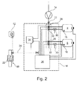
- Fig. 1 and 2 show a mounting support device 2 in the form of a garment 2 for supporting an assembly technician (not shown) at mounting an aircraft or a spacecraft (not shown).
- the device has an amount of chambers 4, 6, 8, which are integrated in areas of the fabric 10 of the garment.
- the chambers are prepared to be filled with a gas (not shown) by means of a connector 12 for a gas pressure source 14.
- a pressure sensor unit 16 in each of the chambers 4, 6, 8 (not shown in 6) is prepared to measure gas pressure in the respective chamber 4, 6, 8.
- An operations status control unit 18 is prepared to produce and adjust an operations status signal.
- the unit 18 comprises sensors 20 producing a respective signal when measuring parameters which indicate requirement of inflation and/or deflation of at least one of the chambers 4, 6, 8 (proximity of a hard object (not shown), e.g., to be bolstered by the inflated respective chamber)
- the sensors 20 are, outside of each chamber 4, 6, 8, operations status sensor units 20 for producing the operations status signal by measuring a present operations status parameter of the device 2.
- a respective push button switch 20 or proximity sensor 20 is the operations status sensor unit 20. It is arranged in the middle of the knee (and, respectively the shoulder and the neck) area of the garment 2 and can recognize, at contact or proximity, a hard object (not shown), e.g., to be bolstered by the inflated respective knee chamber 6 (or, respectively the respective shoulder chamber 4 or neck chamber 8) - consequently cushioning this respective joint by increasing pressure of the accordingly arranged chamber which is integrated here in the garment where the respective joint of a user is covered in the garment 2.
- pressure control 26 may be programmed so that these chambers 6 are not activated in order to avoid bothering the technician by increasing gas pressure in the chamber 6 on the knee which would disturb his walk.
- the operations status control unit 18 further comprises a control panel 22 - a small touch screen 22 to be worn like a wrist watch and in wireless connection 24 (e.g., Bluetooth) with the central parts of the unit 18 integrated in the garment 2 - where a user can active, upon his own decision, inflation and/or deflation of at least one of the chambers 4, 6, 8 by adjusting (or simply "giving") an according operations status signal.
- wireless connection 24 e.g., Bluetooth
- Pressure control units comprising pressure control system elements 26-32 are prepared to adjust gas pressure in the respective chambers 4, 6, 8 depending on the respective present gas pressure in the respective chambers and depending the operations status signal.
- Electrical energy supply of the system is provided by a battery 34.
- the chambers 4, 6, 8 of the mounting support device 2 are prepared to cushion and stiffen, thus bolster and protect the area of fabric 10 in which the chambers are integrated - by means of higher gas pressure depending on the respectively adjusted and/or recognized operations status and operations status program, recognized by means of the sensors 20 in the device.
- the cushioning 6 of the knee areas only by way of example, makes the working position, here on his knees, of the assembly technician more comfortable.
- the garment comprises a jacket 38 with short sleeves and a trouser 40 and a pair of long sleeves (only the right 42 is shown).
- These pieces 38-42 are a system of single garments 38-42 which can be connected to each other by zippers 44 and/or buttons (not shown) and by connectors 46 for the respective electrical and pneumatical feed lines. Consequently, the device 2 can be specialized to particular assembly tasks, which require cushions and/or support only of those body areas of the technician which are covered by the respective garment combination.
- a central control unit 18 including energy supply unit 34 (for example for supplying solenoids 28, 32 being elements of the respective pressure control unit).
- Garment elements of such a system are exchangeable by others with different specialized function and/or different size.
- Chambers (and environment like feed lines and controls required for these chambers; not shown) may be addable onto the fabric 10, e.g., by hook-and-loop fasteners and connected to the unit 18 by line connectors 46 - thus integrating these chambers into the system at arbitrary locations of the garment 38-42.
- the fabric 10 is a robust net material 11 (depicted as a net only in a small area 11, but made of this overall), yet without the typical garment functions of covering and warming the user's body, here only for carrying the described elements of the device 2.
- the garment may, inside, include perforated pneumatic pipes for ventilation and cooling to provide for even more comfort. This is a quite easily addable feature, as a gas (air) pressure source or at least a connector 12 (in the back of the jacket 38) for such supply is anyway part of the device 2.
- the operations status control unit 18 of the mounting support device 2 can be programmed such that different operations statuses and/or operations programs are selectable. Consequently, different combinations of chambers 4, 6, 8, 36 may be activated by accordingly programmed gas pressures.
- the different operations statuses and/or operations programs can be selectable by the user by means of an interface device 50 formed like a wrist watch which may be carried at the wrist of the technician. Adjustment can be performed also by means of voice control and voice recognition and by means of local signals: RFID chips 52 can be used for such local signals which may be located at the place of assembly (e.g., the fuselage) by sticking such chip 52 (formed like an adhesive plaster) there to some exposed wall.
- an operations status program code may be readable from the RFID chip 52 there at the place of assembly by means of an RFID chip receiver and code reader, which is also integrated in the "wrist watch” 50. This then may trigger the operations status of the device according to the invention which is required at this assembly place.
- inflation and deflation can be triggered by operations status programs, adjusting pressure, once initially before beginning of the work, in respectively selected chambers 4, 6, 8, 36 according to the mounting situation for which the respective operations status is programmed. And/Or inflation and deflation can be triggered by operations status sensors 20. And/Or inflation and deflation can be triggered by switches 22 prepared to be activated by the user, which may also be integrated in the "wrist watch" 50.
- Such switches may be programmed to override the sensor 20 signal and/or the operations status program, thus initiating inflation or deflation of a respective chamber triggered by the respective switch 22 irrespective of other programmed and/or any other triggering.
- Such switch may be displayed in a menu accessible on the touch screen 22.
- the chambers 4, 6, 8, 36 of the mounting support device are filled with elastic open porous foam bodies (not shown), the outer shape of which affects the shape of the chambers.
- the foam body's outside is joined to the inside of the chambers.
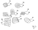
- the foam body comprises, on its outside, a structured pattern of predisposed bending lines 54 and valleys in a pattern of parallel lines. This provides for deformability of the chambers both under pressure and in a deflated mode being explicitly designed in direction and extension. This causes better movability in the areas of the joints of the technician's body, and particularly at non-activated chambers.
- the bending lines 54 can also be designed as limiting lines between segments of the chambers 4, 6, 8, 36 hermetically limiting the segments from each other, thus causing inflatability of the different segments of one chamber separate from each other.
- the predisposed bending lines 56 and/or limiting lines 56 and/or reinforcements 58 and/or valleys 56 and/or segments 58 and/or protrusions 58 can be in rectangular and/or chess board and/or concentrically circular and/or spiral and/or parallel order.
- the chambers 4, 6, 8, 36 are filled with air, and they are connected via feed lines 48 with a pressure source 14 and a pressure control unit 26 such that each of the single chambers can be supplied with gas or evacuated.
- a solenoid 28 is opened entering pressurized air from the pump 14 into the respective chamber 4, 8 ( Fig. 2 ), while the other solenoid 32 is closed being the entry of a second feed line in direction of this respective chamber.
- the first solenoid 28 is closed and the second solenoid 32 is opened, supplying a pump 30, which is functioning according to the Venturi effect, with pressure thus causing vacuum in the feed line between the pump 30 and the respective chamber - evacuating the chamber and thus deflating it.
- a present gas pressure can be measured by means of the respective pressure sensor unit 16, and/or a signal of the operations status sensors 20 may be processed, and/or a manual switch signal triggered by a user by means of the touch pad 22 may be received. If for example a particular gas pressure is exceeded in comparison to a programmed threshold according to an operations status program - for example at increased stress upon the respective chamber - this chamber may be provided with additional gas under control of the pressure control unit 26, so that pressure in this chamber is increased. If the technician is supporting himself upon one of these chambers, pressure increases inside the chamber. This chamber now may be provided with additional gas so that an efficient support of the technician upon this chamber is possible. This also may be triggered by means of the contact switches 20 or proximity sensors 20 as operations status sensors, by means of which the control 18 discovers that there is more pressure required in a chamber, into the direction of which some object or surface is moving.
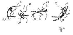
- Fig. 4 shows different positions (standing and working overhead 60, kneeling 62, lying frontside 64 on the belly, lying sideways 66 on hip and shoulder) of a technician inside a fuselage 68. He wears the garment 2 and thus is supported by chambers 4 under his shoulder, chambers 6 under his knee, chambers 8 in his neck, chambers 70 under his hip, and chambers 72 under his chest and belly of the garment 2.
Landscapes
- Health & Medical Sciences (AREA)
- General Health & Medical Sciences (AREA)
- Physical Education & Sports Medicine (AREA)
- Engineering & Computer Science (AREA)
- Textile Engineering (AREA)
- Professional, Industrial, Or Sporting Protective Garments (AREA)
Priority Applications (2)
| Application Number | Priority Date | Filing Date | Title |
|---|---|---|---|
| EP16178690.0A EP3266325A1 (de) | 2016-07-08 | 2016-07-08 | Halterungsvorrichtung zur stützung eines technikers bei der montage |
| JP2017122169A JP2018003234A (ja) | 2016-07-08 | 2017-06-22 | 取付け補助装置及び取付け補助方法 |
Applications Claiming Priority (1)
| Application Number | Priority Date | Filing Date | Title |
|---|---|---|---|
| EP16178690.0A EP3266325A1 (de) | 2016-07-08 | 2016-07-08 | Halterungsvorrichtung zur stützung eines technikers bei der montage |
Publications (1)
| Publication Number | Publication Date |
|---|---|
| EP3266325A1 true EP3266325A1 (de) | 2018-01-10 |
Family
ID=56464028
Family Applications (1)
| Application Number | Title | Priority Date | Filing Date |
|---|---|---|---|
| EP16178690.0A Withdrawn EP3266325A1 (de) | 2016-07-08 | 2016-07-08 | Halterungsvorrichtung zur stützung eines technikers bei der montage |
Country Status (2)
| Country | Link |
|---|---|
| EP (1) | EP3266325A1 (de) |
| JP (1) | JP2018003234A (de) |
Families Citing this family (2)
| Publication number | Priority date | Publication date | Assignee | Title |
|---|---|---|---|---|
| IT201900020416A1 (it) | 2019-11-05 | 2021-05-05 | Alpinestars Res Spa | Dispositivo di protezione indossabile |
| KR102308550B1 (ko) * | 2020-02-28 | 2021-10-06 | 한국기계연구원 | 착용자의 모션의도 인식을 위한 웨어러블 모션측정장치, 이를 이용한 모션인지방법 및 웨어러블 로봇 및 그 제어방법 |
Citations (3)
| Publication number | Priority date | Publication date | Assignee | Title |
|---|---|---|---|---|
| WO2010086781A1 (en) * | 2009-01-30 | 2010-08-05 | Koninklijke Philips Electronics N.V. | Fixation using multiple cushions of two different types |
| US20150307171A1 (en) * | 2012-11-19 | 2015-10-29 | Philip Maechler | Life jacket having additional lifesaving means and lifesaving means for arrangement in buoyancy aids or life jackets |
| DE102014117432A1 (de) | 2014-11-27 | 2016-06-02 | Airbus Operations Gmbh | Montageunterstützungsvorrichtung zum Unterstützen eines Monteurs bei der Montage eines Flugzeugrumpfs |
-
2016
- 2016-07-08 EP EP16178690.0A patent/EP3266325A1/de not_active Withdrawn
-
2017
- 2017-06-22 JP JP2017122169A patent/JP2018003234A/ja active Pending
Patent Citations (3)
| Publication number | Priority date | Publication date | Assignee | Title |
|---|---|---|---|---|
| WO2010086781A1 (en) * | 2009-01-30 | 2010-08-05 | Koninklijke Philips Electronics N.V. | Fixation using multiple cushions of two different types |
| US20150307171A1 (en) * | 2012-11-19 | 2015-10-29 | Philip Maechler | Life jacket having additional lifesaving means and lifesaving means for arrangement in buoyancy aids or life jackets |
| DE102014117432A1 (de) | 2014-11-27 | 2016-06-02 | Airbus Operations Gmbh | Montageunterstützungsvorrichtung zum Unterstützen eines Monteurs bei der Montage eines Flugzeugrumpfs |
Also Published As
| Publication number | Publication date |
|---|---|
| JP2018003234A (ja) | 2018-01-11 |
Similar Documents
| Publication | Publication Date | Title |
|---|---|---|
| US12251826B2 (en) | Pneumatic exomuscle system and method | |
| US20250241817A1 (en) | Modular exoskeleton systems and methods | |
| CN109571431B (zh) | 用于支撑人员的外骨骼系统、作业环境和方法 | |
| JP7535131B2 (ja) | モバイルロボットの適合及び懸垂システム及び方法 | |
| CN107960064B (zh) | 穿戴型支援机器人装置 | |
| US9320674B2 (en) | Inflatable wearable deep pressure therapy systems | |
| US10149638B2 (en) | Method and apparatus for body impact protection | |
| US7150048B2 (en) | Method and apparatus for body impact protection | |
| US7017195B2 (en) | Air bag inflation device | |
| EP2939555B1 (de) | Eigenständige tragbare schutzvorrichtung und schutzbekleidungsanordnung | |
| US20040003455A1 (en) | System for protection from falls | |
| EP3164020B1 (de) | Modulares airbagsystem zum persönlichen schutz | |
| US10499693B2 (en) | Selectively stiffenable assemblies, protective garments for protecting an individual, and systems and methods of using the same | |
| US20060288464A1 (en) | Personal protection device | |
| CA3161113A1 (en) | Powered device to benefit a wearer during skiing | |
| US20140047623A1 (en) | Inflatable fall arrest and fall protection safety apparatus and method of use | |
| WO2004056609A9 (en) | Inflation control system for inflatable garment | |
| WO2000051454A8 (en) | Protective garment | |
| KR100842427B1 (ko) | 골절 방지 의복 | |
| EP3266325A1 (de) | Halterungsvorrichtung zur stützung eines technikers bei der montage | |
| US12501949B2 (en) | Apparatus and method for protection of body areas upon impact | |
| CN219330789U (zh) | 一种护膝组件及急救工作裤 | |
| CN210859643U (zh) | 一种可快速充气的空气减振装置 | |
| KR20250170555A (ko) | 스마트 에어백 보호대 | |
| AU5947098A (en) | Swimback |
Legal Events
| Date | Code | Title | Description |
|---|---|---|---|
| PUAI | Public reference made under article 153(3) epc to a published international application that has entered the european phase |
Free format text: ORIGINAL CODE: 0009012 |
|
| STAA | Information on the status of an ep patent application or granted ep patent |
Free format text: STATUS: THE APPLICATION HAS BEEN PUBLISHED |
|
| AK | Designated contracting states |
Kind code of ref document: A1 Designated state(s): AL AT BE BG CH CY CZ DE DK EE ES FI FR GB GR HR HU IE IS IT LI LT LU LV MC MK MT NL NO PL PT RO RS SE SI SK SM TR |
|
| AX | Request for extension of the european patent |
Extension state: BA ME |
|
| STAA | Information on the status of an ep patent application or granted ep patent |
Free format text: STATUS: THE APPLICATION IS DEEMED TO BE WITHDRAWN |
|
| 18D | Application deemed to be withdrawn |
Effective date: 20180711 |