EP3266086B1 - Method for protection in a mixed power transmission line - Google Patents
Method for protection in a mixed power transmission line Download PDFInfo
- Publication number
- EP3266086B1 EP3266086B1 EP16710008.0A EP16710008A EP3266086B1 EP 3266086 B1 EP3266086 B1 EP 3266086B1 EP 16710008 A EP16710008 A EP 16710008A EP 3266086 B1 EP3266086 B1 EP 3266086B1
- Authority
- EP
- European Patent Office
- Prior art keywords
- section
- power transmission
- transmission line
- ied
- fault
- Prior art date
- Legal status (The legal status is an assumption and is not a legal conclusion. Google has not performed a legal analysis and makes no representation as to the accuracy of the status listed.)
- Active
Links
Images


Classifications
-
- H—ELECTRICITY
- H02—GENERATION; CONVERSION OR DISTRIBUTION OF ELECTRIC POWER
- H02H—EMERGENCY PROTECTIVE CIRCUIT ARRANGEMENTS
- H02H7/00—Emergency protective circuit arrangements specially adapted for specific types of electric machines or apparatus or for sectionalised protection of cable or line systems, and effecting automatic switching in the event of an undesired change from normal working conditions
- H02H7/26—Sectionalised protection of cable or line systems, e.g. for disconnecting a section on which a short-circuit, earth fault, or arc discharge has occured
-
- H—ELECTRICITY
- H02—GENERATION; CONVERSION OR DISTRIBUTION OF ELECTRIC POWER
- H02H—EMERGENCY PROTECTIVE CIRCUIT ARRANGEMENTS
- H02H7/00—Emergency protective circuit arrangements specially adapted for specific types of electric machines or apparatus or for sectionalised protection of cable or line systems, and effecting automatic switching in the event of an undesired change from normal working conditions
- H02H7/26—Sectionalised protection of cable or line systems, e.g. for disconnecting a section on which a short-circuit, earth fault, or arc discharge has occured
- H02H7/265—Sectionalised protection of cable or line systems, e.g. for disconnecting a section on which a short-circuit, earth fault, or arc discharge has occured making use of travelling wave theory
-
- G—PHYSICS
- G01—MEASURING; TESTING
- G01R—MEASURING ELECTRIC VARIABLES; MEASURING MAGNETIC VARIABLES
- G01R31/00—Arrangements for testing electric properties; Arrangements for locating electric faults; Arrangements for electrical testing characterised by what is being tested not provided for elsewhere
- G01R31/08—Locating faults in cables, transmission lines, or networks
- G01R31/081—Locating faults in cables, transmission lines, or networks according to type of conductors
- G01R31/085—Locating faults in cables, transmission lines, or networks according to type of conductors in power transmission or distribution lines, e.g. overhead
-
- H—ELECTRICITY
- H02—GENERATION; CONVERSION OR DISTRIBUTION OF ELECTRIC POWER
- H02H—EMERGENCY PROTECTIVE CIRCUIT ARRANGEMENTS
- H02H1/00—Details of emergency protective circuit arrangements
- H02H1/0007—Details of emergency protective circuit arrangements concerning the detecting means
-
- H—ELECTRICITY
- H02—GENERATION; CONVERSION OR DISTRIBUTION OF ELECTRIC POWER
- H02H—EMERGENCY PROTECTIVE CIRCUIT ARRANGEMENTS
- H02H3/00—Emergency protective circuit arrangements for automatic disconnection directly responsive to an undesired change from normal electric working condition with or without subsequent reconnection ; integrated protection
- H02H3/02—Details
- H02H3/06—Details with automatic reconnection
Definitions
- the present invention relates to fault protection in a mixed power transmission line.
- a mixed power transmission line is a transmission line that consists of overhead and underground line sections. At the very least, a mixed power transmission line has one overhead line section and one underground line section. Such a transmission line is preferred over a homogenous transmission line (i.e. a line that has only an overhead section(s), or a line which only consists of an underground cable(s)) for a variety of reasons including, but not limited to, safety considerations, ease of accessibility of substations in thickly populated locations, ease of grid connection between countries with varying topology, and need for subsea electrification.
- An example where a mixed power transmission line is preferred instead of a homogenous transmission line is when the transmission line is expected to traverse across natural vegetation, rivers etc.
- Reference WO2013/071974A1 describes a method of fault protection in high-voltage power transmission lines comprising multiple sections of different type, i.e. cable or overhead line.
- faults may occur in a mixed power transmission line. Overhead sections of the mixed power transmission line are more prone to faults as they are exposed to disturbances such as lightning strikes, wind-borne debris and the like.
- an auto-reclose functionality is utilized, albeit depending upon the type (underground/overhead) of the homogenous transmission line.
- a switching device such as a circuit breaker, or an auto-recloser may be utilized for the purpose of disconnecting a faulty line from the rest of the power transmission network, thereby mitigating the risk associated with propagation of a fault(s).
- the faults that occur in overhead transmission lines are transient (temporary) in nature, and therefore, such transient faults can be dealt with using an auto-recloser.
- auto-recloser functionality cannot be used in case of underground transmission lines, which are more prone to permanent faults.
- Various aspects of the present invention provide a method and system for protection in response to a fault in a mixed power transmission line (hereafter referred to as 'mixed line').
- a mixed power transmission line hereafter referred to as 'mixed line'.
- the protection is enabled by controlling a switching device connected to the mixed line through an Intelligent Electronic Device (IED).
- IED Intelligent Electronic Device
- the switching device may be a circuit breaker or an auto-recloser. Controlling a switching device includes operating the switching device.
- the mixed line comprises two or more sections with at least one overhead section and at least one underground section.
- the mixed line may be an A/C line.
- Each section of the two or more sections is one of an overhead section and an underground section.
- the mixed line can have two sections, with one of the two sections being an overhead section, and the other section being an underground section. Every two consecutive sections of the mixed line are connected at a junction. Accordingly, in case of a mixed line with two sections (e.g. line with one overhead section and one underground section), there is one junction, in case of a line with three sections (e.g. line with two overhead sections and one underground sections), there are two junctions and so forth.
- the method is implemented by the IED of the mixed line.
- the method may be implemented by an IED associated with a section, a junction, a substation and so forth.
- the IED receives a signal from a measurement equipment connected to the mixed line.
- the measurement equipment can be a current transformer, a potential transformer, a sensor-based measurement equipment (e.g. Rogowski coils) and/or the like, which provides a signal corresponding to current, voltage or other information as sensed from the mixed line.
- the IED performs the step of detecting a travelling wave from the signal received from the measurement equipment.
- a current signal may be digitized and processed by the IED to detect a travelling wave.
- the travelling wave is typically generated due to the fault in a section of the two or more sections of the mixed line.
- the IED also determines a first peak of the travelling wave, and at least one a peak width, a rise time and a discharge time of the first peak.
- the IED identifies the section with the fault based on a comparison of at least one of the peak width, the rise time and the discharge time with a corresponding threshold value of each junction.
- the peak width can be compared with a threshold value of a junction, and depending on whether the peak width is lesser, or greater than the threshold value, it may be determined that the fault lies in an overhead or underground section.
- a peak characteristic may lie in a particular range, and accordingly the fault may be determined in a particular section of the mixed line.
- the mixed power transmission line comprises two sections.
- an overhead section of the two sections may be identified as the section with the fault if at least one of the peak width, the rise time and the discharge time is less than the corresponding threshold value.
- an underground section of the two sections is identified as the section with the fault if at least one of the peak width, the rise time and the discharge time is greater than the corresponding threshold value.
- the determination of which section has the fault may also depend on the ordering of the sections with respect to the IED.
- the corresponding threshold value is predetermined for each junction and is stored in the IED.
- the corresponding threshold value is predetermined for each junction based on one or more of an analysis of a history of information associated with one or more faults at the junction, fine-tuning of a default value over a period of time, and electrical characteristics of the mixed power transmission line.
- fault characteristics of a junction(s) of the mixed line may be determined at the time of installation of the mixed line, and such characteristics may be used for defining the threshold value(s) for the junction.
- experiments may be conducted for determining the threshold value(s) for the junction. Such experiments can include physically / virtually simulating faults for a line.
- the threshold for a junction(s) may be set as a default value in the beginning, and later fine-tuned according to actual values collected upon occurrence of a fault(s).
- the IED performs the step of controlling the switching device based on the section with the fault identified based on the comparison, for protection in response to the fault. For example, the IED sends a command to enable operation of an auto-recloser if an overhead section is detected to be faulty. Taking another example, the IED sends a command to disable operation of the auto-recloser if an underground section is detected to be faulty.
- the present invention envisages a system and method for protection in response to a fault in a mixed power transmission line (referred to as 'mixed line' hereafter).
- the mixed line typically includes at least one underground section and at least one overhead section. Two consecutive sections in a mixed line are connected at a junction.
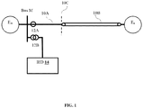
- FIG.1 illustrates a first embodiment of the present invention, wherein there is shown a mixed line comprising an overhead section and as underground section.
- the mixed line in accordance with the embodiment includes one overhead section denoted by a reference numeral 10A, and one underground section denoted by a reference numeral 10B. Further, the overhead section 10A is connected to the underground section 10B at a junction 10C.
- the mixed line connects two substations Em and En, as shown in FIG.1 .
- the overhead section 10A originates at the substation Em and the underground section 10B terminates at the substation En as shown in FIG.1 .
- the measurement equipment is connected to the substation Em. Measurement equipment may be connected at one or more of the substations Em and En.
- the measurement equipment may be a Current Transformer (CT), a Potential Transformer (PT), a sensor-based measurement equipment etc.
- CT Current Transformer
- PT Potential Transformer
- the measurement equipment includes a current transformer 12A and a voltage transformer 12B.
- an Intelligent Electronic Device (IED) 14 is connected to voltage transformer 12B.
- IED 14 may be connected with the current transformer, or it may receive a signal from other equipment.
- travelling waves are generated as a consequence of occurrence of the fault.
- the signal(s) from the measurement equipment are monitored, preferably continuously.
- IED 14 monitors the signal received from either the current transformer 12A or potential transformer 12B (depending upon whether current signals are to be sensed or voltage signals are to be sensed).
- the current transformer 12A senses current of the mixed line
- the potential transformer 12B senses voltage of the mixed line.
- the measurement corresponds to the point in the mixed line, wherein the measurement equipment is connected. In case of AC line, the measurement will reflect current / voltage for each phase (of the multi-phase line).
- the signal is digitized and processed by the IED 14, to detect a travelling wave therefrom.
- Clark transformation is applied either to the current signal or the voltage signal.
- aerial mode (alpha component or beta component) and ground mode components of the (current or voltage) signal are obtained.
- the alpha component or beta component is input to a second order band pass/low pass filter (e.g. Butterworth filter).
- the band pass/low pass filter is used to filter out unwanted noise, and extract the travelling waves within a predetermined frequency band.
- the upper cut-off frequency and the lower cut-off frequency for the band pass/low pass filter are set as per the sampling frequency.
- the output of the band pass/low pass filter is then input to a second order mid-reject filter, whose output provides the travelling wave (signal).
- This process can be applied for a single phase, or repeated for each phase in a multi-phase line. Accordingly, the IED can implement the method for single phase A/C line as well as three-phase A/C line.
- the IED 14 also determines the travelling wave characteristics. A first peak of the travelling wave is taken into consideration by the IED 14, given the fact that the current measurements and/or voltage measurements corresponding to second, third and further peaks are typically prone to errors and disturbances.
- the IED 14 determines at least one of a peak width, rise time and discharge time, of the first peak of the extracted travelling wave. Subsequently, the IED 14 compares one or more of the peak width, rise time and discharge time, with the corresponding threshold value for the peak width, rise time and discharge time stored therein (stored in IED 14).
- the threshold values for peak width, rise time and discharge time are predetermined for the junction 10C (or multiple junctions as the case may be).
- a peak characteristic value (i.e. value of one of peak width, rise time, discharge time etc.) is compared with the threshold values for the different junctions, and the section with the fault is identified to be the section that precedes the junction for which the peak characteristic value exceeds the threshold value.
- tpd1, trt1, tdt1, tpd2, trt2, tdt2, ... tpdn, trtn,tdtn represents the threshold values of peak width, rise time and discharge time for j1, j2 .. jn respectively.
- the first peak characteristic (say PDf is compared with tpd1, tpd2 .. tpdn). Assume that PDf ⁇ tp2 and PDf > tp3. Accordingly, IED 14 identifies that the fault is in the third section that lies between j2 and j3. It will be apparent that there may be different ways in which the threshold values may be used for comparing with the actual values and identifying the section with the fault.
- the IED 14 communicates with a switching device (not shown in figures) to enable (or continue performing) / disable a protection function in the mixed line.
- the switching device may be an auto-recloser, which is controlled by the IED 14. Further, the auto-reclose functionality may be continued only in the event that the overhead section (e.g. 10A) is determined to be faulty. Otherwise, if the underground section 10B is determined to be faulty, the auto-reclose functionality is disabled (i.e. auto-recloser opens after a fault and does not reclose).
- a mixed power transmission line comprising a first overhead section 10A, an underground section 10B, and a second overhead section 10E.
- first overhead section 10A is electrically connected to underground section 10B via a junction 10C.
- the underground section 10B is electrically connected to the second overhead section 10E via a junction 10D.
- the mixed line 100A connects two substations Em and En, wherein the first overhead section 10A originates at substation Em, and terminates at junction 10c, from the underground section originates.
- the underground section terminates at junction 10D, from where the second overhead section 10E originates.
- the second overhead section 10E terminates at substation En.
- Measurement equipment 12 and 14 may be connected at buses of substations Em and En, as shown in FIG. 2 .
- the measurement equipment may include a current transformer 12A and a voltage transformer 12B, and the measurement equipment may include a current transformer 14A and a voltage transformer 14B.
- the signal(s) from 12A and/or 12B may be processed by IED 14.
- IED 16 may process the signal from 14A and/or 14B.
- the processing performed at either IED 14 or IED 16, is for identifying the section with the fault based on travelling wave characteristics (similar to the process of identifying the section with the fault described above with respect to FIG. 1 ).
- IED 14 and IED 16 work independently. Each IED identifies the section with the fault based on the processing the IED performs according to the signal it receives. Therefore, IED 14 may identify the section with the fault based on analysis of signal from 12A / 12B. Likewise, IED 16 may identify the section with the fault based on analysis of signal from 14A / 14B. The processing performed by the IEDs is for identifying the section with the fault based on identification and comparison of travelling wave characteristics, as described hereinabove (refer description of FIG. 1 ).
- FIG. 3 which illustrates a flowchart of a method for protection in response to a fault in a mixed power transmission line (such as mixed line described in conjunction with FIG. 1 and FIG. 2 ).
- the method may be implemented by an IED (such as IED 14 or 16).
- the IED may be located at a section, a junction, a substation etc.
- the IED is connected with a measurement equipment such as a current transformer, potential transformer, a sensor-based measurement equipment etc.
- the IED receives a signal from the measurement equipment. As described above, the signal may be of current, voltage or other electrical parameter sensed from the mixed line.
- the IED detects a travelling wave from the signal.
- the IED digitizes and processes the signal to detect the travelling wave (refer description of FIG. 1 regarding detection of travelling wave).
- At 304 determines a first peak of the travelling wave and at least one of a peak width, a rise time and a discharge time of the first peak (again refer description of FIG. 1 ).
- the IED compares one or more of the peak width, the rise time and the discharge time with a corresponding threshold value for each junction. For example, in case of a line with one junction, the IED compares the peak width, the rise time and the discharge time with the threshold for peak width, the threshold for rise time and the threshold for discharge time for the junction.
- the fault is determined to be in the overhead or underground section respectively.
- the IED compares the peak characteristic value with the threshold values of various junctions to determine which section has the fault.
- the IED controls a switching device (e.g. auto-recloser) according to the identified section.
- the auto-recloser operation may be enabled by the IED if the section having the fault is an overhead section.
- enabled means that the auto-recloser works normally, and clears momentary faults in the overhead section.
- disabled means that the auto-recloser will open on detection of the fault, and will not reclose (the fault being considered as not momentary).
- the advantages envisaged by the present invention include the realization of a system and method for effective and efficient fault section identification, in a mixed power transmission line.
- the system and method also provide for selective enablement of auto-reclosing functionality across the mixed line, depending upon the location (i.e. section) of the fault.
- the present invention provides protection from measurement made by one IED, wherein the IED may be located at a section, a junction, or a terminal, without having to use measurements made at other locations.
Landscapes
- Engineering & Computer Science (AREA)
- Theoretical Computer Science (AREA)
- Physics & Mathematics (AREA)
- General Physics & Mathematics (AREA)
- Locating Faults (AREA)
Description
- The present invention relates to fault protection in a mixed power transmission line.
- A mixed power transmission line is a transmission line that consists of overhead and underground line sections. At the very least, a mixed power transmission line has one overhead line section and one underground line section. Such a transmission line is preferred over a homogenous transmission line (i.e. a line that has only an overhead section(s), or a line which only consists of an underground cable(s)) for a variety of reasons including, but not limited to, safety considerations, ease of accessibility of substations in thickly populated locations, ease of grid connection between countries with varying topology, and need for subsea electrification. An example where a mixed power transmission line is preferred instead of a homogenous transmission line, is when the transmission line is expected to traverse across natural vegetation, rivers etc. Reference
WO2013/071974A1 , for example, describes a method of fault protection in high-voltage power transmission lines comprising multiple sections of different type, i.e. cable or overhead line. - As in case of a homogenous transmission line, faults may occur in a mixed power transmission line. Overhead sections of the mixed power transmission line are more prone to faults as they are exposed to disturbances such as lightning strikes, wind-borne debris and the like. In case of homogenous transmission lines, an auto-reclose functionality is utilized, albeit depending upon the type (underground/overhead) of the homogenous transmission line. A switching device such as a circuit breaker, or an auto-recloser may be utilized for the purpose of disconnecting a faulty line from the rest of the power transmission network, thereby mitigating the risk associated with propagation of a fault(s). Typically, the faults that occur in overhead transmission lines are transient (temporary) in nature, and therefore, such transient faults can be dealt with using an auto-recloser. However, in case of underground transmission lines, which are more prone to permanent faults, auto-recloser functionality cannot be used.
- Therefore, in case of power transmission networks comprising mixed transmission lines, auto-reclosers need to be controlled in a selective manner. In case of occurrence of fault in an underground section, the auto-recloser operation should be disabled, given the permanent nature of the fault. Therefore, there was felt a need for a system and method that is effective and efficient in terms of identifying an occurrence of a fault in a mixed power transmission line, and providing for appropriate and efficient protection.
- Various aspects of the present invention provide a method and system for protection in response to a fault in a mixed power transmission line (hereafter referred to as 'mixed line'). For example, there may be electrical faults in the mixed line due to disturbances like as lightning strikes, wind-borne debris etc. In such a case, a portion of the line or the entire line may be disconnected from the rest of power transmission network to prevent propagation of faults / damage to electrical equipment. The protection is enabled by controlling a switching device connected to the mixed line through an Intelligent Electronic Device (IED). The switching device may be a circuit breaker or an auto-recloser. Controlling a switching device includes operating the switching device.
- The mixed line comprises two or more sections with at least one overhead section and at least one underground section. The mixed line may be an A/C line. Each section of the two or more sections is one of an overhead section and an underground section. For example, the mixed line can have two sections, with one of the two sections being an overhead section, and the other section being an underground section. Every two consecutive sections of the mixed line are connected at a junction. Accordingly, in case of a mixed line with two sections (e.g. line with one overhead section and one underground section), there is one junction, in case of a line with three sections (e.g. line with two overhead sections and one underground sections), there are two junctions and so forth.
- The method is implemented by the IED of the mixed line. For example, the method may be implemented by an IED associated with a section, a junction, a substation and so forth. In accordance with the method, the IED receives a signal from a measurement equipment connected to the mixed line. For example, the measurement equipment can be a current transformer, a potential transformer, a sensor-based measurement equipment (e.g. Rogowski coils) and/or the like, which provides a signal corresponding to current, voltage or other information as sensed from the mixed line.
- The IED performs the step of detecting a travelling wave from the signal received from the measurement equipment. As an example, a current signal may be digitized and processed by the IED to detect a travelling wave. The travelling wave is typically generated due to the fault in a section of the two or more sections of the mixed line. The IED also determines a first peak of the travelling wave, and at least one a peak width, a rise time and a discharge time of the first peak.
- The IED identifies the section with the fault based on a comparison of at least one of the peak width, the rise time and the discharge time with a corresponding threshold value of each junction. For example, the peak width can be compared with a threshold value of a junction, and depending on whether the peak width is lesser, or greater than the threshold value, it may be determined that the fault lies in an overhead or underground section. Taking another example, a peak characteristic may lie in a particular range, and accordingly the fault may be determined in a particular section of the mixed line. Take a case where the mixed power transmission line comprises two sections. Here, an overhead section of the two sections may be identified as the section with the fault if at least one of the peak width, the rise time and the discharge time is less than the corresponding threshold value. Alternately, an underground section of the two sections is identified as the section with the fault if at least one of the peak width, the rise time and the discharge time is greater than the corresponding threshold value. The determination of which section has the fault may also depend on the ordering of the sections with respect to the IED.
- The corresponding threshold value is predetermined for each junction and is stored in the IED. Here, the corresponding threshold value is predetermined for each junction based on one or more of an analysis of a history of information associated with one or more faults at the junction, fine-tuning of a default value over a period of time, and electrical characteristics of the mixed power transmission line. For example, fault characteristics of a junction(s) of the mixed line may be determined at the time of installation of the mixed line, and such characteristics may be used for defining the threshold value(s) for the junction. Taking another example, experiments may be conducted for determining the threshold value(s) for the junction. Such experiments can include physically / virtually simulating faults for a line. Taking yet another example, the threshold for a junction(s) may be set as a default value in the beginning, and later fine-tuned according to actual values collected upon occurrence of a fault(s).
- The IED performs the step of controlling the switching device based on the section with the fault identified based on the comparison, for protection in response to the fault. For example, the IED sends a command to enable operation of an auto-recloser if an overhead section is detected to be faulty. Taking another example, the IED sends a command to disable operation of the auto-recloser if an underground section is detected to be faulty.
- The subject matter of the invention will be explained in more detail in the following text with reference to exemplary embodiments which are illustrated in attached drawings in which:
-
Fig. 1 is a simplified diagram of a system for protection in response to a fault in a mixed power transmission line, in accordance with an embodiment of the invention; -
Fig. 2 is a simplified diagram of the system for protection in response to the fault in the mixed power transmission line, in accordance with another embodiment of the invention; and -
Fig. 3 is a flowchart of a method for protection in response to the fault in the mixed power transmission line, in accordance with an embodiment of the invention. - The present invention envisages a system and method for protection in response to a fault in a mixed power transmission line (referred to as 'mixed line' hereafter). The mixed line typically includes at least one underground section and at least one overhead section. Two consecutive sections in a mixed line are connected at a junction.
-
FIG.1 illustrates a first embodiment of the present invention, wherein there is shown a mixed line comprising an overhead section and as underground section. The mixed line in accordance with the embodiment includes one overhead section denoted by areference numeral 10A, and one underground section denoted by areference numeral 10B. Further, theoverhead section 10A is connected to theunderground section 10B at ajunction 10C. The mixed line connects two substations Em and En, as shown inFIG.1 . Theoverhead section 10A originates at the substation Em and theunderground section 10B terminates at the substation En as shown inFIG.1 . As shown inFIG.1 , the measurement equipment is connected to the substation Em. Measurement equipment may be connected at one or more of the substations Em and En. The measurement equipment may be a Current Transformer (CT), a Potential Transformer (PT), a sensor-based measurement equipment etc. - In accordance with the embodiment shown in
Fig. 1 , the measurement equipment includes acurrent transformer 12A and avoltage transformer 12B. Again referring toFIG.1 , an Intelligent Electronic Device (IED) 14 is connected tovoltage transformer 12B. However,IED 14 may be connected with the current transformer, or it may receive a signal from other equipment. - In accordance with the present invention, whenever a fault occurs at any section of the mixed line, travelling waves are generated as a consequence of occurrence of the fault. In order to detect travelling waves, the signal(s) from the measurement equipment are monitored, preferably continuously. For example,
IED 14 monitors the signal received from either thecurrent transformer 12A orpotential transformer 12B (depending upon whether current signals are to be sensed or voltage signals are to be sensed). Typically, thecurrent transformer 12A senses current of the mixed line, while thepotential transformer 12B senses voltage of the mixed line. The measurement corresponds to the point in the mixed line, wherein the measurement equipment is connected. In case of AC line, the measurement will reflect current / voltage for each phase (of the multi-phase line). - In accordance with the present invention, the signal is digitized and processed by the
IED 14, to detect a travelling wave therefrom. At theIED 14, Clark transformation is applied either to the current signal or the voltage signal. Subsequently aerial mode (alpha component or beta component) and ground mode components of the (current or voltage) signal are obtained. The alpha component or beta component is input to a second order band pass/low pass filter (e.g. Butterworth filter). The band pass/low pass filter is used to filter out unwanted noise, and extract the travelling waves within a predetermined frequency band. The upper cut-off frequency and the lower cut-off frequency for the band pass/low pass filter are set as per the sampling frequency. The output of the band pass/low pass filter is then input to a second order mid-reject filter, whose output provides the travelling wave (signal). This process can be applied for a single phase, or repeated for each phase in a multi-phase line. Accordingly, the IED can implement the method for single phase A/C line as well as three-phase A/C line. - The
IED 14 also determines the travelling wave characteristics. A first peak of the travelling wave is taken into consideration by theIED 14, given the fact that the current measurements and/or voltage measurements corresponding to second, third and further peaks are typically prone to errors and disturbances. TheIED 14 determines at least one of a peak width, rise time and discharge time, of the first peak of the extracted travelling wave. Subsequently, theIED 14 compares one or more of the peak width, rise time and discharge time, with the corresponding threshold value for the peak width, rise time and discharge time stored therein (stored in IED 14). The threshold values for peak width, rise time and discharge time are predetermined for thejunction 10C (or multiple junctions as the case may be). - The
IED 14, post comparison of at least one of the values of peak width, rise time and discharge time, with the corresponding threshold value, determines whether the compared value(s) is less or more than the threshold value(s). In the event that at least one of the values of peak width, rise time and discharge time is lesser than the corresponding threshold value, theIED 14 determines theoverhead section 10A to be faulty. Otherwise, in the event that theIED 14 determines at least one of the values of peak width, rise time and discharge time to be greater than the corresponding threshold value, then theIED 14 identifies theunderground section 10B to be faulty. This is in case of a mixed line having two sections. Also, it is assumed that the section of the line closer to theIED 14 is the overhead section, and the section distant from theIED 14 is the underground section. - In case of a mixed line with multiple sections, a peak characteristic value (i.e. value of one of peak width, rise time, discharge time etc.) is compared with the threshold values for the different junctions, and the section with the fault is identified to be the section that precedes the junction for which the peak characteristic value exceeds the threshold value. Take a case of a line with junctions j1, j2, ... jn, wherein tpd1, trt1, tdt1, tpd2, trt2, tdt2, ... tpdn, trtn,tdtn represents the threshold values of peak width, rise time and discharge time for j1, j2 .. jn respectively. Here, the first peak characteristic (say PDf is compared with tpd1, tpd2 .. tpdn). Assume that PDf<tp2 and PDf > tp3. Accordingly,
IED 14 identifies that the fault is in the third section that lies between j2 and j3. It will be apparent that there may be different ways in which the threshold values may be used for comparing with the actual values and identifying the section with the fault. - Subsequently, the
IED 14 communicates with a switching device (not shown in figures) to enable (or continue performing) / disable a protection function in the mixed line. The switching device may be an auto-recloser, which is controlled by theIED 14. Further, the auto-reclose functionality may be continued only in the event that the overhead section (e.g. 10A) is determined to be faulty. Otherwise, if theunderground section 10B is determined to be faulty, the auto-reclose functionality is disabled (i.e. auto-recloser opens after a fault and does not reclose). This is because a fault occurring in the underground section is typically long lasting, and immune to automatic rectification, and hence necessitates rectification measures to be manually implemented post a shutdown of the (underground) section. Therefore, in case of theunderground section 10B being determined as faulty, switching device is utilized to isolate the (underground) section having the fault, from the remaining sections of the mixed transmission line. - Referring to
FIG.2 , there is shown a mixed power transmission line comprising a firstoverhead section 10A, anunderground section 10B, and a secondoverhead section 10E. As shown, firstoverhead section 10A is electrically connected tounderground section 10B via ajunction 10C. Further, theunderground section 10B is electrically connected to the secondoverhead section 10E via ajunction 10D. Also, as shown, the mixed line 100A connects two substations Em and En, wherein the firstoverhead section 10A originates at substation Em, and terminates at junction 10c, from the underground section originates. The underground section terminates atjunction 10D, from where the secondoverhead section 10E originates. The secondoverhead section 10E terminates at substation En.Measurement equipment 12 and 14 may be connected at buses of substations Em and En, as shown inFIG. 2 . - The measurement equipment may include a
current transformer 12A and avoltage transformer 12B, and the measurement equipment may include a current transformer 14A and a voltage transformer 14B. The signal(s) from 12A and/or 12B may be processed byIED 14. Similarly,IED 16 may process the signal from 14A and/or 14B. The processing performed at eitherIED 14 orIED 16, is for identifying the section with the fault based on travelling wave characteristics (similar to the process of identifying the section with the fault described above with respect toFIG. 1 ). - In the embodiment illustrated in
Fig. 2 ,IED 14 andIED 16 work independently. Each IED identifies the section with the fault based on the processing the IED performs according to the signal it receives. Therefore,IED 14 may identify the section with the fault based on analysis of signal from 12A / 12B. Likewise,IED 16 may identify the section with the fault based on analysis of signal from 14A / 14B. The processing performed by the IEDs is for identifying the section with the fault based on identification and comparison of travelling wave characteristics, as described hereinabove (refer description ofFIG. 1 ). - Referring to
FIG. 3 , which illustrates a flowchart of a method for protection in response to a fault in a mixed power transmission line (such as mixed line described in conjunction withFIG. 1 andFIG. 2 ). The method may be implemented by an IED (such asIED 14 or 16). The IED may be located at a section, a junction, a substation etc. Also, the IED is connected with a measurement equipment such as a current transformer, potential transformer, a sensor-based measurement equipment etc. The IED receives a signal from the measurement equipment. As described above, the signal may be of current, voltage or other electrical parameter sensed from the mixed line. - At 302, the IED detects a travelling wave from the signal. The IED digitizes and processes the signal to detect the travelling wave (refer description of
FIG. 1 regarding detection of travelling wave). At 304 determines a first peak of the travelling wave and at least one of a peak width, a rise time and a discharge time of the first peak (again refer description ofFIG. 1 ). Thereafter, at 306, the IED compares one or more of the peak width, the rise time and the discharge time with a corresponding threshold value for each junction. For example, in case of a line with one junction, the IED compares the peak width, the rise time and the discharge time with the threshold for peak width, the threshold for rise time and the threshold for discharge time for the junction. Here, depending on whether the compared value is less than or greater than the corresponding threshold value, the fault is determined to be in the overhead or underground section respectively. - In case, the line has multiple junctions, the IED compares the peak characteristic value with the threshold values of various junctions to determine which section has the fault. At 308, the IED controls a switching device (e.g. auto-recloser) according to the identified section. For example, the auto-recloser operation may be enabled by the IED if the section having the fault is an overhead section. Here, enabled means that the auto-recloser works normally, and clears momentary faults in the overhead section. Taking another example, wherein the auto-recloser operation is disabled if the section having the fault is an underground section. Here, disabled means that the auto-recloser will open on detection of the fault, and will not reclose (the fault being considered as not momentary).
- The advantages envisaged by the present invention include the realization of a system and method for effective and efficient fault section identification, in a mixed power transmission line. The system and method also provide for selective enablement of auto-reclosing functionality across the mixed line, depending upon the location (i.e. section) of the fault. The present invention provides protection from measurement made by one IED, wherein the IED may be located at a section, a junction, or a terminal, without having to use measurements made at other locations.
Claims (9)
- A method for protection in response to a fault in a mixed power transmission line by controlling a switching device connected to the mixed power transmission line through an Intelligent Electronic Device (IED), the mixed power transmission line comprising two or more sections with at least one overhead section (10A) and at least one underground section (10B), each section of the two or more sections being one of an overhead section (10A) and an underground section (10B), wherein every two consecutive sections of the mixed power transmission line are connected at a junction (10C), the method being implemented by the IED of the mixed power transmission line, wherein the IED receives a signal from a measurement equipment connected to the mixed power transmission line, the IED performing:detecting (302) a travelling wave from the signal received from the measurement equipment, wherein the travelling wave is generated due to the fault in a section of the two or more sections of the mixed power transmission line;determining (304) a first peak of the travelling wave and at least one a peak width, a rise time and a discharge time of the first peak;identifying (306) the section with the fault based on a comparison of at least one of the peak width, the rise time and the discharge time with a corresponding threshold value of each junction (10C), wherein the corresponding threshold value is predetermined for each junction (10C) and is stored in the IED; andcontrolling (308) the switching device based on the section with the fault identified based on the comparison, for protecting the mixed line.
- The method of claim 1, wherein the mixed power transmission line comprises two sections, and an overhead section (10A) of the two sections is identified as the section with the fault if at least one of the peak width, the rise time and the discharge time is less than the corresponding threshold value.
- The method of claim 1, wherein the mixed power transmission line comprises two sections, and an underground section (10B) of the two sections is identified as the section with the fault if at least one of the peak width, the rise time and the discharge time is greater than the corresponding threshold value.
- The method of claim 1, wherein the corresponding threshold value is predetermined for each junction (10C) based on one or more of an analysis of a history of information associated with one or more faults at the junction (10C), fine-tuning of a default value over a period of time, and electrical characteristics of the mixed power transmission line.
- The method of claim 1, wherein the switching device is an auto-recloser.
- The method of claim 5, wherein the auto-recloser operation is enabled on the section with the fault identified being an overhead section (10A).
- The method of claim 5, wherein the auto-recloser operation is disabled on the section with the fault identified being an underground section (10B).
- The method of claim 1, wherein the switching device is a circuit breaker.
- The method of claim 1, wherein the mixed power transmission line connects two substations, and the IED operates from one of the two substation.
Applications Claiming Priority (2)
| Application Number | Priority Date | Filing Date | Title |
|---|---|---|---|
| IN1016CH2015 | 2015-03-03 | ||
| PCT/IB2016/051197 WO2016139613A1 (en) | 2015-03-03 | 2016-03-03 | Method for protection in a mixed power transmission line |
Publications (2)
| Publication Number | Publication Date |
|---|---|
| EP3266086A1 EP3266086A1 (en) | 2018-01-10 |
| EP3266086B1 true EP3266086B1 (en) | 2018-12-19 |
Family
ID=55532241
Family Applications (1)
| Application Number | Title | Priority Date | Filing Date |
|---|---|---|---|
| EP16710008.0A Active EP3266086B1 (en) | 2015-03-03 | 2016-03-03 | Method for protection in a mixed power transmission line |
Country Status (4)
| Country | Link |
|---|---|
| US (1) | US10447030B2 (en) |
| EP (1) | EP3266086B1 (en) |
| CN (1) | CN107438929B (en) |
| WO (1) | WO2016139613A1 (en) |
Families Citing this family (14)
| Publication number | Priority date | Publication date | Assignee | Title |
|---|---|---|---|---|
| US10310004B2 (en) * | 2015-09-18 | 2019-06-04 | Schweitzer Engineering Laboratories, Inc. | Time-domain differential line protection of electric power delivery systems |
| CN108139438B (en) | 2015-10-13 | 2021-03-12 | 施瓦哲工程实验有限公司 | Power system monitoring using high frequency signals |
| CN109564256B (en) | 2016-12-28 | 2021-01-15 | Abb电网瑞士股份公司 | Traveling wave based method for locating faults in transmission lines and apparatus therefor |
| US11137436B2 (en) | 2017-09-22 | 2021-10-05 | Schweitzer Engineering Laboratories, Inc. | Secure traveling wave distance protection in an electric power delivery system |
| US10989752B2 (en) | 2017-09-22 | 2021-04-27 | Schweitzer Engineering Laboratories, Inc. | Distance protection using traveling waves in an electric power delivery system |
| US11038342B2 (en) | 2017-09-22 | 2021-06-15 | Schweitzer Engineering Laboratories, Inc. | Traveling wave identification using distortions for electric power system protection |
| EP3710842B1 (en) | 2017-11-17 | 2022-06-01 | Hitachi Energy Switzerland AG | Traveling wave based fault location using unsynchronized measurements for transmission lines |
| CN110692140B (en) | 2017-12-14 | 2023-07-04 | 富士电机株式会社 | Semiconductor device |
| US11360137B2 (en) * | 2017-12-29 | 2022-06-14 | Hitachi Energy Switzerland Ag | Parameter free identification of fault location in multi-terminal power transmission lines |
| US11280834B2 (en) | 2018-08-30 | 2022-03-22 | Schweitzer Engineering Laboratories, Inc. | Detection of low-energy events in an electric power system |
| US10677834B2 (en) | 2018-09-14 | 2020-06-09 | Schweitzer Engineering Laboratories, Inc. | Distance protection of electric power delivery systems using time domain and frequency domain |
| US10641815B2 (en) | 2018-09-27 | 2020-05-05 | Schweitzer Engineering Laboratories, Inc. | Secure distance protection of electric power delivery systems under transient conditions |
| JP7429339B2 (en) | 2020-01-30 | 2024-02-08 | ヒタチ・エナジー・リミテッド | Parameter-independent traveling wave-based fault localization using asynchronous measurements |
| US11735907B2 (en) | 2021-02-03 | 2023-08-22 | Schweitzer Engineering Laboratories, Inc. | Traveling wave overcurrent protection for electric power delivery systems |
Family Cites Families (8)
| Publication number | Priority date | Publication date | Assignee | Title |
|---|---|---|---|---|
| US4766549A (en) | 1984-11-30 | 1988-08-23 | Electric Power Research Institute, Inc. | Single-ended transmission line fault locator |
| EP2332225B1 (en) * | 2008-09-08 | 2015-11-04 | ABB Research Ltd. | Apparatus and method for adaptive fault detection in mv distribution circuits |
| BRPI0923437B1 (en) * | 2008-12-15 | 2021-03-09 | Accenture Global Services Limited | method of determining a type of failure in a multiphase power network |
| WO2013056144A1 (en) * | 2011-10-12 | 2013-04-18 | Schweitzer Engineering Laboratories, Inc. | Fault location using traveling waves |
| EP2780998B1 (en) * | 2011-11-17 | 2016-05-11 | ABB Research Ltd. | Fault protection in mixed high-voltage transmission lines |
| US20150081236A1 (en) * | 2013-09-16 | 2015-03-19 | Schweitzer Engineering Laboratories, Inc. | Traveling wave validation using estimated fault location |
| US20150081235A1 (en) * | 2013-09-16 | 2015-03-19 | Schweitzer Engineering Laboratories, Inc. | Fault location using traveling waves by calculating traveling wave arrival time |
| US8990036B1 (en) * | 2013-09-16 | 2015-03-24 | Schweitzer Engineering Laboratories, Inc. | Power line parameter adjustment and fault location using traveling waves |
-
2016
- 2016-03-03 WO PCT/IB2016/051197 patent/WO2016139613A1/en not_active Ceased
- 2016-03-03 CN CN201680013052.XA patent/CN107438929B/en active Active
- 2016-03-03 EP EP16710008.0A patent/EP3266086B1/en active Active
- 2016-03-03 US US15/549,198 patent/US10447030B2/en active Active
Non-Patent Citations (1)
| Title |
|---|
| None * |
Also Published As
| Publication number | Publication date |
|---|---|
| WO2016139613A1 (en) | 2016-09-09 |
| CN107438929B (en) | 2019-03-26 |
| CN107438929A (en) | 2017-12-05 |
| US10447030B2 (en) | 2019-10-15 |
| US20180034265A1 (en) | 2018-02-01 |
| EP3266086A1 (en) | 2018-01-10 |
Similar Documents
| Publication | Publication Date | Title |
|---|---|---|
| US10447030B2 (en) | Method for protection in a mixed power transmission line | |
| US11056874B2 (en) | Fault detection and protection during steady state using traveling waves | |
| CN104779594B (en) | Small current neutral grounding power system phase fault and single-phase grounding comprehensive protecting method | |
| US10739414B2 (en) | Determining status of electric power transmission lines in an electric power transmission system | |
| US11143715B2 (en) | Broken conductor detection in a multiple-phase electric power delivery system | |
| US8300369B2 (en) | System and method for polyphase ground-fault circuit-interrupters | |
| US10859639B2 (en) | Fault-type identification in an electric power delivery system using composite signals | |
| US10333291B2 (en) | Multiple generator ground fault detection | |
| EP3304668B1 (en) | Travelling wave protection of a transmission line based on high-pass filtering | |
| RU2583452C2 (en) | Directed detection of resistive ground fault and rupture of conductor of medium voltage | |
| EP2332225B1 (en) | Apparatus and method for adaptive fault detection in mv distribution circuits | |
| WO2019139973A1 (en) | Temporary overvoltage and ground fault overvoltage protection based on arrester current measurement and analysis | |
| WO2011157305A1 (en) | Fault protection of hvdc transmission lines | |
| US10641815B2 (en) | Secure distance protection of electric power delivery systems under transient conditions | |
| US20180226796A1 (en) | Method and system for improved operation of power grid components in the presence of direct current (dc) | |
| CN112534280A (en) | System and method for locating faults on a multi-phase electrical network using positive and negative sequence voltage variations | |
| CN107315128A (en) | A kind of distributed earthing wire-selecting method and system based on GOOSE | |
| WO2019025840A1 (en) | Method and device for fault section identification in multi-terminal mixed lines | |
| Tiwari et al. | Review on protection issues with penetration of distributed generation in distribution system | |
| CA3014132A1 (en) | Apparatus for determination of a ground fault and associated method | |
| US11728638B2 (en) | Normally open tie pulse testing | |
| US11962140B2 (en) | Coordination of protective elements in an electric power system | |
| US12113350B2 (en) | Power supply system, protection coordination method and program | |
| CN206832927U (en) | A kind of Little Current Ground Connection System | |
| CN114336537B (en) | Station domain protection method and device based on channel alarm information |
Legal Events
| Date | Code | Title | Description |
|---|---|---|---|
| STAA | Information on the status of an ep patent application or granted ep patent |
Free format text: STATUS: THE INTERNATIONAL PUBLICATION HAS BEEN MADE |
|
| PUAI | Public reference made under article 153(3) epc to a published international application that has entered the european phase |
Free format text: ORIGINAL CODE: 0009012 |
|
| STAA | Information on the status of an ep patent application or granted ep patent |
Free format text: STATUS: REQUEST FOR EXAMINATION WAS MADE |
|
| 17P | Request for examination filed |
Effective date: 20170823 |
|
| AK | Designated contracting states |
Kind code of ref document: A1 Designated state(s): AL AT BE BG CH CY CZ DE DK EE ES FI FR GB GR HR HU IE IS IT LI LT LU LV MC MK MT NL NO PL PT RO RS SE SI SK SM TR |
|
| AX | Request for extension of the european patent |
Extension state: BA ME |
|
| DAV | Request for validation of the european patent (deleted) | ||
| DAX | Request for extension of the european patent (deleted) | ||
| GRAP | Despatch of communication of intention to grant a patent |
Free format text: ORIGINAL CODE: EPIDOSNIGR1 |
|
| STAA | Information on the status of an ep patent application or granted ep patent |
Free format text: STATUS: GRANT OF PATENT IS INTENDED |
|
| RIC1 | Information provided on ipc code assigned before grant |
Ipc: H02H 3/06 20060101ALI20180625BHEP Ipc: H02H 7/26 20060101AFI20180625BHEP Ipc: G01R 31/08 20060101ALI20180625BHEP Ipc: H02H 1/00 20060101ALI20180625BHEP |
|
| INTG | Intention to grant announced |
Effective date: 20180713 |
|
| GRAS | Grant fee paid |
Free format text: ORIGINAL CODE: EPIDOSNIGR3 |
|
| GRAA | (expected) grant |
Free format text: ORIGINAL CODE: 0009210 |
|
| STAA | Information on the status of an ep patent application or granted ep patent |
Free format text: STATUS: THE PATENT HAS BEEN GRANTED |
|
| AK | Designated contracting states |
Kind code of ref document: B1 Designated state(s): AL AT BE BG CH CY CZ DE DK EE ES FI FR GB GR HR HU IE IS IT LI LT LU LV MC MK MT NL NO PL PT RO RS SE SI SK SM TR |
|
| REG | Reference to a national code |
Ref country code: GB Ref legal event code: FG4D |
|
| REG | Reference to a national code |
Ref country code: CH Ref legal event code: EP |
|
| REG | Reference to a national code |
Ref country code: IE Ref legal event code: FG4D |
|
| REG | Reference to a national code |
Ref country code: DE Ref legal event code: R096 Ref document number: 602016008464 Country of ref document: DE |
|
| REG | Reference to a national code |
Ref country code: AT Ref legal event code: REF Ref document number: 1079714 Country of ref document: AT Kind code of ref document: T Effective date: 20190115 |
|
| REG | Reference to a national code |
Ref country code: NL Ref legal event code: MP Effective date: 20181219 |
|
| PG25 | Lapsed in a contracting state [announced via postgrant information from national office to epo] |
Ref country code: BG Free format text: LAPSE BECAUSE OF FAILURE TO SUBMIT A TRANSLATION OF THE DESCRIPTION OR TO PAY THE FEE WITHIN THE PRESCRIBED TIME-LIMIT Effective date: 20190319 Ref country code: LT Free format text: LAPSE BECAUSE OF FAILURE TO SUBMIT A TRANSLATION OF THE DESCRIPTION OR TO PAY THE FEE WITHIN THE PRESCRIBED TIME-LIMIT Effective date: 20181219 Ref country code: HR Free format text: LAPSE BECAUSE OF FAILURE TO SUBMIT A TRANSLATION OF THE DESCRIPTION OR TO PAY THE FEE WITHIN THE PRESCRIBED TIME-LIMIT Effective date: 20181219 Ref country code: LV Free format text: LAPSE BECAUSE OF FAILURE TO SUBMIT A TRANSLATION OF THE DESCRIPTION OR TO PAY THE FEE WITHIN THE PRESCRIBED TIME-LIMIT Effective date: 20181219 Ref country code: NO Free format text: LAPSE BECAUSE OF FAILURE TO SUBMIT A TRANSLATION OF THE DESCRIPTION OR TO PAY THE FEE WITHIN THE PRESCRIBED TIME-LIMIT Effective date: 20190319 Ref country code: FI Free format text: LAPSE BECAUSE OF FAILURE TO SUBMIT A TRANSLATION OF THE DESCRIPTION OR TO PAY THE FEE WITHIN THE PRESCRIBED TIME-LIMIT Effective date: 20181219 |
|
| REG | Reference to a national code |
Ref country code: LT Ref legal event code: MG4D |
|
| REG | Reference to a national code |
Ref country code: AT Ref legal event code: MK05 Ref document number: 1079714 Country of ref document: AT Kind code of ref document: T Effective date: 20181219 |
|
| PG25 | Lapsed in a contracting state [announced via postgrant information from national office to epo] |
Ref country code: AL Free format text: LAPSE BECAUSE OF FAILURE TO SUBMIT A TRANSLATION OF THE DESCRIPTION OR TO PAY THE FEE WITHIN THE PRESCRIBED TIME-LIMIT Effective date: 20181219 Ref country code: SE Free format text: LAPSE BECAUSE OF FAILURE TO SUBMIT A TRANSLATION OF THE DESCRIPTION OR TO PAY THE FEE WITHIN THE PRESCRIBED TIME-LIMIT Effective date: 20181219 Ref country code: RS Free format text: LAPSE BECAUSE OF FAILURE TO SUBMIT A TRANSLATION OF THE DESCRIPTION OR TO PAY THE FEE WITHIN THE PRESCRIBED TIME-LIMIT Effective date: 20181219 Ref country code: GR Free format text: LAPSE BECAUSE OF FAILURE TO SUBMIT A TRANSLATION OF THE DESCRIPTION OR TO PAY THE FEE WITHIN THE PRESCRIBED TIME-LIMIT Effective date: 20190320 |
|
| PG25 | Lapsed in a contracting state [announced via postgrant information from national office to epo] |
Ref country code: NL Free format text: LAPSE BECAUSE OF FAILURE TO SUBMIT A TRANSLATION OF THE DESCRIPTION OR TO PAY THE FEE WITHIN THE PRESCRIBED TIME-LIMIT Effective date: 20181219 |
|
| PG25 | Lapsed in a contracting state [announced via postgrant information from national office to epo] |
Ref country code: PT Free format text: LAPSE BECAUSE OF FAILURE TO SUBMIT A TRANSLATION OF THE DESCRIPTION OR TO PAY THE FEE WITHIN THE PRESCRIBED TIME-LIMIT Effective date: 20190419 Ref country code: CZ Free format text: LAPSE BECAUSE OF FAILURE TO SUBMIT A TRANSLATION OF THE DESCRIPTION OR TO PAY THE FEE WITHIN THE PRESCRIBED TIME-LIMIT Effective date: 20181219 Ref country code: IT Free format text: LAPSE BECAUSE OF FAILURE TO SUBMIT A TRANSLATION OF THE DESCRIPTION OR TO PAY THE FEE WITHIN THE PRESCRIBED TIME-LIMIT Effective date: 20181219 Ref country code: PL Free format text: LAPSE BECAUSE OF FAILURE TO SUBMIT A TRANSLATION OF THE DESCRIPTION OR TO PAY THE FEE WITHIN THE PRESCRIBED TIME-LIMIT Effective date: 20181219 Ref country code: ES Free format text: LAPSE BECAUSE OF FAILURE TO SUBMIT A TRANSLATION OF THE DESCRIPTION OR TO PAY THE FEE WITHIN THE PRESCRIBED TIME-LIMIT Effective date: 20181219 |
|
| PG25 | Lapsed in a contracting state [announced via postgrant information from national office to epo] |
Ref country code: SK Free format text: LAPSE BECAUSE OF FAILURE TO SUBMIT A TRANSLATION OF THE DESCRIPTION OR TO PAY THE FEE WITHIN THE PRESCRIBED TIME-LIMIT Effective date: 20181219 Ref country code: IS Free format text: LAPSE BECAUSE OF FAILURE TO SUBMIT A TRANSLATION OF THE DESCRIPTION OR TO PAY THE FEE WITHIN THE PRESCRIBED TIME-LIMIT Effective date: 20190419 Ref country code: RO Free format text: LAPSE BECAUSE OF FAILURE TO SUBMIT A TRANSLATION OF THE DESCRIPTION OR TO PAY THE FEE WITHIN THE PRESCRIBED TIME-LIMIT Effective date: 20181219 Ref country code: EE Free format text: LAPSE BECAUSE OF FAILURE TO SUBMIT A TRANSLATION OF THE DESCRIPTION OR TO PAY THE FEE WITHIN THE PRESCRIBED TIME-LIMIT Effective date: 20181219 Ref country code: SM Free format text: LAPSE BECAUSE OF FAILURE TO SUBMIT A TRANSLATION OF THE DESCRIPTION OR TO PAY THE FEE WITHIN THE PRESCRIBED TIME-LIMIT Effective date: 20181219 |
|
| REG | Reference to a national code |
Ref country code: DE Ref legal event code: R097 Ref document number: 602016008464 Country of ref document: DE |
|
| PLBE | No opposition filed within time limit |
Free format text: ORIGINAL CODE: 0009261 |
|
| STAA | Information on the status of an ep patent application or granted ep patent |
Free format text: STATUS: NO OPPOSITION FILED WITHIN TIME LIMIT |
|
| PG25 | Lapsed in a contracting state [announced via postgrant information from national office to epo] |
Ref country code: MC Free format text: LAPSE BECAUSE OF FAILURE TO SUBMIT A TRANSLATION OF THE DESCRIPTION OR TO PAY THE FEE WITHIN THE PRESCRIBED TIME-LIMIT Effective date: 20181219 Ref country code: AT Free format text: LAPSE BECAUSE OF FAILURE TO SUBMIT A TRANSLATION OF THE DESCRIPTION OR TO PAY THE FEE WITHIN THE PRESCRIBED TIME-LIMIT Effective date: 20181219 Ref country code: DK Free format text: LAPSE BECAUSE OF FAILURE TO SUBMIT A TRANSLATION OF THE DESCRIPTION OR TO PAY THE FEE WITHIN THE PRESCRIBED TIME-LIMIT Effective date: 20181219 |
|
| REG | Reference to a national code |
Ref country code: CH Ref legal event code: PL |
|
| 26N | No opposition filed |
Effective date: 20190920 |
|
| PG25 | Lapsed in a contracting state [announced via postgrant information from national office to epo] |
Ref country code: LU Free format text: LAPSE BECAUSE OF NON-PAYMENT OF DUE FEES Effective date: 20190303 |
|
| REG | Reference to a national code |
Ref country code: BE Ref legal event code: MM Effective date: 20190331 |
|
| PG25 | Lapsed in a contracting state [announced via postgrant information from national office to epo] |
Ref country code: CH Free format text: LAPSE BECAUSE OF NON-PAYMENT OF DUE FEES Effective date: 20190331 Ref country code: LI Free format text: LAPSE BECAUSE OF NON-PAYMENT OF DUE FEES Effective date: 20190331 Ref country code: IE Free format text: LAPSE BECAUSE OF NON-PAYMENT OF DUE FEES Effective date: 20190303 |
|
| PG25 | Lapsed in a contracting state [announced via postgrant information from national office to epo] |
Ref country code: SI Free format text: LAPSE BECAUSE OF FAILURE TO SUBMIT A TRANSLATION OF THE DESCRIPTION OR TO PAY THE FEE WITHIN THE PRESCRIBED TIME-LIMIT Effective date: 20181219 Ref country code: BE Free format text: LAPSE BECAUSE OF NON-PAYMENT OF DUE FEES Effective date: 20190331 |
|
| PG25 | Lapsed in a contracting state [announced via postgrant information from national office to epo] |
Ref country code: TR Free format text: LAPSE BECAUSE OF FAILURE TO SUBMIT A TRANSLATION OF THE DESCRIPTION OR TO PAY THE FEE WITHIN THE PRESCRIBED TIME-LIMIT Effective date: 20181219 |
|
| PG25 | Lapsed in a contracting state [announced via postgrant information from national office to epo] |
Ref country code: MT Free format text: LAPSE BECAUSE OF NON-PAYMENT OF DUE FEES Effective date: 20190303 |
|
| REG | Reference to a national code |
Ref country code: DE Ref legal event code: R081 Ref document number: 602016008464 Country of ref document: DE Owner name: HITACHI ENERGY SWITZERLAND AG, CH Free format text: FORMER OWNER: ABB SCHWEIZ AG, BADEN, CH Ref country code: DE Ref legal event code: R082 Ref document number: 602016008464 Country of ref document: DE Representative=s name: DENNEMEYER & ASSOCIATES RECHTSANWALTSGESELLSCH, DE Ref country code: DE Ref legal event code: R081 Ref document number: 602016008464 Country of ref document: DE Owner name: HITACHI ENERGY LTD, CH Free format text: FORMER OWNER: ABB SCHWEIZ AG, BADEN, CH Ref country code: DE Ref legal event code: R082 Ref document number: 602016008464 Country of ref document: DE Representative=s name: DENNEMEYER & ASSOCIATES S.A., DE Ref country code: DE Ref legal event code: R081 Ref document number: 602016008464 Country of ref document: DE Owner name: ABB POWER GRIDS SWITZERLAND AG, CH Free format text: FORMER OWNER: ABB SCHWEIZ AG, BADEN, CH |
|
| PG25 | Lapsed in a contracting state [announced via postgrant information from national office to epo] |
Ref country code: CY Free format text: LAPSE BECAUSE OF FAILURE TO SUBMIT A TRANSLATION OF THE DESCRIPTION OR TO PAY THE FEE WITHIN THE PRESCRIBED TIME-LIMIT Effective date: 20181219 |
|
| PG25 | Lapsed in a contracting state [announced via postgrant information from national office to epo] |
Ref country code: HU Free format text: LAPSE BECAUSE OF FAILURE TO SUBMIT A TRANSLATION OF THE DESCRIPTION OR TO PAY THE FEE WITHIN THE PRESCRIBED TIME-LIMIT; INVALID AB INITIO Effective date: 20160303 |
|
| REG | Reference to a national code |
Ref country code: GB Ref legal event code: 732E Free format text: REGISTERED BETWEEN 20211104 AND 20211110 |
|
| REG | Reference to a national code |
Ref country code: DE Ref legal event code: R081 Ref document number: 602016008464 Country of ref document: DE Owner name: HITACHI ENERGY SWITZERLAND AG, CH Free format text: FORMER OWNER: ABB POWER GRIDS SWITZERLAND AG, BADEN, CH Ref country code: DE Ref legal event code: R081 Ref document number: 602016008464 Country of ref document: DE Owner name: HITACHI ENERGY LTD, CH Free format text: FORMER OWNER: ABB POWER GRIDS SWITZERLAND AG, BADEN, CH |
|
| PG25 | Lapsed in a contracting state [announced via postgrant information from national office to epo] |
Ref country code: MK Free format text: LAPSE BECAUSE OF FAILURE TO SUBMIT A TRANSLATION OF THE DESCRIPTION OR TO PAY THE FEE WITHIN THE PRESCRIBED TIME-LIMIT Effective date: 20181219 |
|
| P01 | Opt-out of the competence of the unified patent court (upc) registered |
Effective date: 20230527 |
|
| REG | Reference to a national code |
Ref country code: DE Ref legal event code: R082 Ref document number: 602016008464 Country of ref document: DE Representative=s name: DENNEMEYER & ASSOCIATES RECHTSANWALTSGESELLSCH, DE Ref country code: DE Ref legal event code: R082 Ref document number: 602016008464 Country of ref document: DE Representative=s name: DENNEMEYER & ASSOCIATES S.A., DE Ref country code: DE Ref legal event code: R081 Ref document number: 602016008464 Country of ref document: DE Owner name: HITACHI ENERGY LTD, CH Free format text: FORMER OWNER: HITACHI ENERGY SWITZERLAND AG, BADEN, CH |
|
| REG | Reference to a national code |
Ref country code: GB Ref legal event code: 732E Free format text: REGISTERED BETWEEN 20240718 AND 20240724 |
|
| REG | Reference to a national code |
Ref country code: DE Ref legal event code: R082 Ref document number: 602016008464 Country of ref document: DE Representative=s name: DENNEMEYER & ASSOCIATES RECHTSANWALTSGESELLSCH, DE |
|
| PGFP | Annual fee paid to national office [announced via postgrant information from national office to epo] |
Ref country code: GB Payment date: 20260324 Year of fee payment: 11 |
|
| PGFP | Annual fee paid to national office [announced via postgrant information from national office to epo] |
Ref country code: DE Payment date: 20260319 Year of fee payment: 11 |
|
| PGFP | Annual fee paid to national office [announced via postgrant information from national office to epo] |
Ref country code: FR Payment date: 20260320 Year of fee payment: 11 |