EP3265651B1 - Pumpable two component resin - Google Patents
Pumpable two component resin Download PDFInfo
- Publication number
- EP3265651B1 EP3265651B1 EP16759380.5A EP16759380A EP3265651B1 EP 3265651 B1 EP3265651 B1 EP 3265651B1 EP 16759380 A EP16759380 A EP 16759380A EP 3265651 B1 EP3265651 B1 EP 3265651B1
- Authority
- EP
- European Patent Office
- Prior art keywords
- resin
- catalyst
- line
- borehole
- inhibitor
- Prior art date
- Legal status (The legal status is an assumption and is not a legal conclusion. Google has not performed a legal analysis and makes no representation as to the accuracy of the status listed.)
- Active
Links
Images







Classifications
-
- E—FIXED CONSTRUCTIONS
- E21—EARTH OR ROCK DRILLING; MINING
- E21D—SHAFTS; TUNNELS; GALLERIES; LARGE UNDERGROUND CHAMBERS
- E21D20/00—Setting anchoring-bolts
- E21D20/02—Setting anchoring-bolts with provisions for grouting
- E21D20/028—Devices or accesories for injecting a grouting liquid in a bore-hole
-
- E—FIXED CONSTRUCTIONS
- E21—EARTH OR ROCK DRILLING; MINING
- E21D—SHAFTS; TUNNELS; GALLERIES; LARGE UNDERGROUND CHAMBERS
- E21D20/00—Setting anchoring-bolts
- E21D20/02—Setting anchoring-bolts with provisions for grouting
Definitions
- the present invention relates to a two component resin and, more particularly, to a pumpable two component resin system and method for the installation of mine roof bolts.
- the roof of a mine is conventionally supported by tensioning the roof with steel bolts inserted into boreholes drilled in the mine roof that reinforce the unsupported rock formation above the mine roof.
- the mine roof bolt may be anchored mechanically to the rock formation by engagement of an expansion assembly on the distal end of the mine roof bolt with the rock formation.
- the mine roof bolt may be adhesively bonded to the rock formation with a resin bonding material inserted into the borehole.
- a combination of mechanical anchoring and resin bonding may also be employed by using both an expansion assembly and resin bonding material.
- Resin is typically inserted into the mine roof borehole in the form of a two component plastic cartridge having one component containing a curable resin composition and another component containing a curing agent (catalyst).
- the two component resin cartridge is inserted into the blind end of the borehole and the mine roof bolt is inserted into the borehole such that the end of the mine roof bolt ruptures the two component resin cartridge.
- the compartments within the resin cartridge are shredded and the components are mixed.
- the resin mixture fills the annular area between the borehole wall and the shaft of the mine roof bolt.
- US 2014/0140773 A1 discloses a resin injection apparatus for use in connection with a drilling apparatus.
- the apparatus includes fluid containers for the resin and catalyst with each having a separate pump.
- WO 2014/190382 A1 is directed to a self-drilling rock bolt assembly including reservoirs, priming pumps, displacement pumps and an injection nozzle.
- US 2007/0264088 A1 discloses a system for embedding rock anchors including a drill rod, feed pumps and drive motors, reservoirs and a control device.
- a pumpable resin system for installation of mine roof bolts comprises a resin reservoir configured to receive resin, a catalyst reservoir configured to receive catalyst, a resin pump arrangement in fluid communication with the resin reservoir, a catalyst pump arrangement in fluid communication with the catalyst reservoir, a delivery line in fluid communication with at least one of the resin pump arrangement and the catalyst pump arrangement, and a bolter arm configured to drill boreholes and install mine roof bolts.
- the delivery line is configured to deliver resin and catalyst from the resin reservoir and the catalyst reservoir to a borehole via the bolter arm.
- the resin reservoir comprises a resin feed cylinder configured to receive a resin cartridge and the catalyst reservoir comprises a catalyst feed cylinder configured to receive a catalyst cartridge.
- the resin feed cylinder and the catalyst feed cylinder each comprise a cap, the cap of the resin feed cylinder defining a gap between the cap of the resin feed cylinder and the resin feed cylinder, and the cap of the catalyst feed cylinder defining a gap between the cap of the catalyst feed cylinder and the catalyst feed cylinder.
- the gaps are configured to allow air to escape the respective resin feed cylinder and the catalyst feed cylinder during compression of resin and catalyst cartridges within the respective resin feed cylinder and the catalyst feed cylinder.
- the delivery line may include a resin line in fluid communication with the resin pump arrangement and a catalyst line in fluid communication with the catalyst pump arrangement.
- the resin line and the catalyst line may be received by a static mixer, with the delivery further including a grout tube is in fluid communication with the static mixer and configured to deliver a resin/catalyst mix into a borehole.
- the system may further include an inhibitor reservoir, an inhibitor pump arrangement, and an inhibitor line in fluid communication with the inhibitor pump arrangement, with the inhibitor line configured to deliver inhibitor from the inhibitor reservoir to the borehole to define a fast set section and a slow set section within a borehole.
- the resin pump arrangement may include a resin cylinder pump and the catalyst pump arrangement may include a catalyst cylinder pump, with the resin cylinder pump and the catalyst cylinder pump are slaved together and controlled by a hydraulic piston and hydraulic pump.
- a method of installing a mine roof bolt includessupplying resin from the resin feed cylinder to the resin line via the resin cylinder pump, supplying catalyst from the catalyst feed cylinder to the catalyst line via the catalyst cylinder pump, injecting resin and catalyst through the resin and catalyst lines into a borehole and installing a mine roof bolt in the borehole using a bolter arm .
- the method may include actuating a hydraulic piston to supply the resin and catalyst to the resin and catalyst lines.
- the method may also include supplying an inhibitor from an inhibitor reservoir to the borehole, with the inhibitor configured to react slower with the resin than the catalyst reacts with the resin to define a fast set section and a slow set section within the borehole.
- the inhibitor may be supplied from the inhibitor reservoir via an inhibitor pump arrangement and an inhibitor line in fluid communication with the inhibitor pump arrangement.
- the resin line and the catalyst line may be received by a static mixer with a grout tube being in fluid communication with the static mixer. The grout tube may be secured to the bolter arm and moveable relative to the bolter arm.
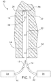
- a pumpable two component resin system 10 includes a delivery line formed by a resin line 12 and a catalyst line 14 that are configured to deliver grout, such as a resin 28 and a catalyst 30 to a borehole.
- the resin line 12 and the catalyst line 14 each have an inlet 16, 20 and an outlet 18, 22.
- the inlet 16 of the resin line 12 is connected to and in fluid communication with a resin pump 24.
- the inlet 20 of the catalyst line 14 is connected to and in fluid communication with a catalyst pump 26.
- the resin pump 24 and the catalyst pump 26 are connected to respective reservoirs (not shown) containing resin 28 and catalyst 30.
- the resin line 12 and the catalyst line 14 may be secured to each other via bands 32 to aid the insertion of the lines 12, 14 within a borehole 34.
- the resin and catalyst pumps 24, 26 may be chop check pumps, although other types of pumps suitable for pumping material of a high viscosity may also be utilized.
- the flow of each pump 24, 26 is calibrated to provide the proper ratio between the resin 28 and the catalyst 30, which is preferably 2:1 or 66% resin and 33% catalyst using a water-based catalyst. The ratio can range from about 4:1 to 3:2. With an oil-based catalyst, a 9:1 +/- 5% ratio is utilized.
- the flow of each pump 24, 26 may be calibrated by adjusting the air inlet pressure and the diameter of the outlets 18, 22 of the resin line 12 and the catalyst line 14.
- the resin 28 is a filled resin having 10-25% inert filler, such as limestone.
- the resin may have a viscosity of about 100,000-400,000 centipoise.
- Conventional polyurethane resin typically has a viscosity of less than 10,000 centipoise. The use of a high viscosity resin generally makes pumping more difficult, but provides significant cost savings through the use of the less expensive filler.
- the resin and catalyst lines 12, 14 are inserted into the borehole 34 and the pumps 24, 26 are activated simultaneously to fill the borehole 34 with the resin 28 and catalyst 30.
- the lines 12, 14 are forced out of the borehole 34 by the displaced material ensuring a fully filled borehole 34.
- a packer or plug slightly smaller than the inner diameter of the borehole 34 may be installed just before the end of the lines 12, 14.
- the resin 28 and the catalyst 30 will contact each other and will react to create a very fine barrier, which will prevent further reaction from occurring between the resin 28 and the catalyst 30.
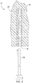
- a mine roof bolt 36 is then inserted into the borehole 34 and rotated to mix the resin 28 and catalyst 30. After the mine roof bolt 36 has been fully inserted, as shown in Fig. 3 , the mixed resin 28 and catalyst 30 hardens and cures to securely anchor the bolt 36 within the borehole 34.
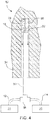
- the pumpable two component resin system 10 may further include a connector 38, such as a wye or T connector, for receiving the resin line 12 and the catalyst line 14 from the resin pump 24 and the catalyst pump 26, respectively.
- a connector 38 such as a wye or T connector
- the use of the connector 38 allows the resin and catalyst lines 12, 14 to be combined into a single grout tube 39 that is connected to the resin pump 24 and catalyst pump 26 through the connector 38.
- the single grout tube 39 acts as a delivery line and configured to introduce the resin 28 and catalyst 30 into the borehole 34.
- the system 10 using the connector 38 would operate in the same manner as described above in connection with Figs. 1-3 .
- a third aspect of a pumpable two component resin system 40 includes a resin line 42 and a catalyst line 44.
- the resin line 42 and the catalyst line 44 each have an inlet 46, 52 and an outlet 48, 54.
- the inlets 46, 52 of the resin line 42 and the catalyst line 44 are connected to and in fluid communication with a resin pump 56 and a catalyst pump 58, respectively, in a similar manner as shown in Fig. 1 and discussed above.
- the outlets 48, 54 of the resin line 42 and the catalyst line 44 are connected to a connector 60, such as a wye or T fitting, which is secured to a static mixer 62.
- the static mixer 62 is configured to mix the resin 28 and catalyst 30 prior to being pumped into a borehole 64.
- a single grout tube 66 acts as a delivery line and is secured to the static mixer 62 and configured to introduce the resin and catalyst as a mixture into the borehole 64.
- a fourth aspect of a pumpable two component resin system 70 includes a delivery line formed by a resin line 72, a standard catalyst line 74, and an inhibited catalyst line 76.
- the system 70 of Figs. 6 and 7 operates in a similar manner to the system 10 shown in Fig. 1 and described above, but includes the inhibited catalyst line 76 to provide within the borehole 34 a fast set section 78 (such as at the blind end of the borehole 34) and a slow set section 79 (further spaced from the blind end of the borehole 34).
- Inhibited catalyst or inhibitor 77 reacts more slowly with the resin from the resin line 72 than the standard catalyst 30 from the standard catalyst line 74 reacts with the resin 28 from the resin line 72.
- the sections allow a mine roof bolt to be anchored at the fast set section and subsequently tensioned while the slow set section is still curing.
- the lines 72, 74, 76 may each be inserted into the borehole 34.
- the resin line 72 and the standard catalyst line 74 may then be activated or placed in the "ON" state as shown in Fig. 6 such that the resin 28 and standard catalyst 30 are delivered to the borehole 34 with the inhibited catalyst line 74 placed in the "OFF" state.
- the resin 28 and standard catalyst 30 are provided along a predetermined length of the borehole 34 to define the fast set section 78.
- the standard catalyst line 74 is deactivated or placed in the "OFF" state and the inhibited catalyst line 76 is placed in the "ON" state such that resin 28 and inhibited catalyst 30 are provided along a predetermined length of the borehole to define the slow set section 79.
- the fast set section 78 of resin 28 and catalyst 30 will harden and set up faster than the slow set section 79 due to differences between the catalyst 30 provided by the standard catalyst line 74 and the inhibited catalyst line 76, which allows a mine roof bolt to be installed and point anchored at the blind end of the borehole 34 and subsequently tensioned while the slow set section 79 is still curing.
- a fifth aspect of a pumpable two component resin system 80 includes a resin line 82, a standard catalyst line 84, and a catalyst inhibitor line 86.
- the system 80 of Fig. 8 is similar to the system shown in Figs. 6 and 7 and described above, but feeds the catalyst inhibitor line 86 directly to the standard catalyst line 84.
- the catalyst inhibitor line 86 would only be operated or pumped at the sections where a slower set time is desired.
- Connecting the catalyst inhibitor line 86 to the standard catalyst line 84 prevents the need for a third line positioned within the borehole 34.
- This system 80 could also be utilized by pre-mixing the resin and the catalyst.
- the system 80 may also utilize two or more resin compositions in addition to using two or more catalysts. In particular, the system 80 may utilize a plurality of resins and catalysts to optimize their performance and cost.
- a sixth aspect of a pumpable two component resin system 90 includes a resin line 92 and a catalyst line 94.
- the resin line 92 and the catalyst line 94 each have an inlet 96, 102 and an outlet 98, 104.
- the inlet 96 of the resin line 92 is connected to and in fluid communication with a resin cylinder pump 106.
- the inlet 102 of the catalyst line 94 is connected to and in fluid communication with a catalyst cylinder pump 108.
- the outlets 98, 104 are connected to a grout tube 66 acting as a delivery line, although other suitable arrangements may be utilized.
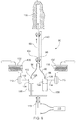
- the resin cylinder pump 106 and the catalyst cylinder pump 108 are connected to respective supply pumps 110, 112 via a resin supply line 114 and a catalyst supply line 116.
- the supply pumps 110, 112 pump resin 126 and catalyst 128 from respective reservoirs 118, 120 through the respective resin supply line 114 and catalyst supply line 116 and into the respective resin cylinder pump 106 and catalyst cylinder pump 108.
- the resin cylinder pump 106 and the catalyst cylinder pump 108 are slaved together to inject the resin 126 and catalyst 128 at about a constant 2:1 volumetric ratio, although other suitable ratios may be utilized.
- the slaved pumps 106, 108 are controlled by a separate piston 113, which is operated by a hydraulic pump 115.
- the hydraulic pump 115 may have a maximum output pressure of 8.274 ⁇ 10 6 Pa (1,200 psi), which has been demonstrated to be effective in injecting resin 126 and catalyst 128 into a borehole 130 through a 0.0127 m (1 ⁇ 2") diameter tube over 15.24 m (50 feet) in length, although other suitable pumps may be utilized.
- the supply pumps 110, 112 are diaphragm pumps, although other types of pumps suitable for pumping material of a high viscosity may also be utilized, such as chop check pumps, progressive cavity pumps, etc.
- the pumpable two component resin system 90 shown in Fig. 9 generally operates in the same manner as the system 10 shown in Figs. 1-3 and discussed above.
- the supply pumps 110, 112 are used to fill respective cylinders 122, 124 of the resin cylinder pump 106 and catalyst cylinder pump 108 to a predetermined level for each of the cylinders 122, 124.
- the resin cylinder pump 106 and the catalyst cylinder pump 108 are then activated to dispense resin 126 and catalyst 128 simultaneously.
- the resin cylinder 122 should generally be about two times larger in volume relative to the catalyst cylinder 124.
- the resin 126 and catalyst 128 will fill the borehole 130 and then a bolt is subsequently inserted into the borehole 130.
- the resin cylinder pump 106 and the catalyst cylinder pump 108 may then be recharged via the supply pumps 110, 112.
- the reservoirs 118, 120 may each be hoppers with a twin auger arrangement 132, which is shown more clearly in Fig. 11 , although other suitable reservoir arrangements may be utilized.
- the twin auger arrangement 132 allows the components to be continuously mixed to prevent separation or drying out of the resin and catalyst 126, 128.
- the reservoirs 118, 120 may be supplied using large "chubs" or cartridges 139 or other containers containing the resin and catalyst 126, 128.
- the grout tube 66 is connected to a bolter arm 140 and is moveable relative to the bolter arm 140 to allow the insertion of the grout tube 66 within the borehole 130 for delivery of the grout.
- the system shown in Fig. 9 may utilize any other arrangements shown in Figs. 1-8 and described above.
- the pumpable two component resin system 90 shown in Fig. 9 and described above may utilize progressive cavity pumps for the supply pumps 110, 112 rather than the diaphragm pumps shown in Fig. 9 .
- the system 90 would operate in the same manner as described above.
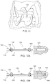
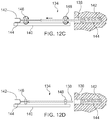
- the method 134 may provide an automated arrangement for injecting and installing a mine roof bolt using a bolting machine (not shown). After drilling a borehole 136 using a bolting machine, a grout tube 138 is inserted into the borehole 136 using the bolter arm 140 of the bolting machine as shown in Fig. 12A . Resin and catalyst components 142, 144 are injected into the borehole 136 and the grout tube 138 is retracted at a suitable rate to prevent air pockets or the flow of resin and catalyst 142, 144 from bypassing the tip of the grout tube 138 as shown in Figs. 12B and 12C .
- the grout tube 138 is removed from the borehole 136 as shown in Fig. 12D .
- a mine roof bolt may be subsequently inserted into the borehole 136 and rotated to mine the resin and catalyst 142, 144 in the same manner as described above in connection with Figs. 1-3 .
- the method shown in Figs. 12A-12D may utilize any of the systems and arrangements shown in Figs. 1-11 .
- the bolting machine may be configured to automatically drill the borehole 136, inject the resin and catalyst 142, 144 into the borehole 136, and install a mine roof bolt by inserting the bolt into the borehole 136 and rotating the bolt to mix the resin and catalyst 142, 144.
- the bolting machine may utilize a controller, such as a PLC, and one or more sensors to control the installation of the mine roof bolt.
- the grout tube 138 may be driven by a first and second set of drive wheels 146, 148, although any suitable arrangement for inserting and retracting the grout tube 138 may be utilized.
- a pumpable two component resin system 150 is similar to the system 90 shown in Fig. 9 and discussed above. However, rather than utilizing supply pumps 110, 112 as in the system 90 of Fig. 9 , the system 150 of Fig. 13 utilizes a feed pump arrangement 152 having a resin feed cylinder 154 and a catalyst feed cylinder 156 that are slaved together to feed the resin cylinder pump 106 and catalyst cylinder pump 108, respectively.
- the cylinders 154, 156 are controlled by a main piston 158, which is operated by a hydraulic pump (not shown).
- the resin feed cylinder 154 and catalyst feed cylinder 156 may be supplied with resin and catalyst cartridges 160, 162 or other suitable arrangements as discussed above.
- the resin and catalyst cartridges 160, 162 may be fed into the cylinders 154, 156 by removing a cap 164, which is discussed in more detail below and shown in Figs. 15 and 16 .
- Figs. 14A-14D further methods of installing a mine roof bolt using the systems 10, 40, 70, 80, 90 discussed above are shown.
- the mixing and/or non-mixing of the resin and catalyst can be controlled during injection by the amount of turbulence introduced into a grout injection line.
- the basic properties that control the amount of turbulence are the viscosities of the two components, the internal diameter and length of the injection tube, and the flow rate. Changes in any of these parameters can change the characteristics of the flow from turbulent (mixing) to laminar (non-mixing). This flow rate property and being able to control whether the flow is turbulent or laminar, or a combination thereof, is important for proper installation of mine roof bolts in the systems 10, 40, 70, 80, 90 discussed above.
- mixing of the resin and catalyst is undesirable because the resin can set before the bolt can be installed. However, in other situations, fully mixing or partially mixing the resin and catalyst during injection may be desirable.
- a system 200 uses a divided injection tube 202 in order to keep the two components separate. When the resin and catalyst exit the injection tube they will lay side by side in the borehole. Turbulent and laminar flow is not an issue with this system 200 and method.
- the method of using this system 200 typically includes: drilling the borehole; inserting the injection tube 202 into the borehole; pumping resin and catalyst at any flow rate to prevent mixing; simultaneously with pumping the resin and catalyst, retracting the injection tube 202 at a set rate to prevent voids and flowback ahead of the injection tube 202; and installing a mine roof bolt (not shown) and spinning the mine roof bolt to mix the resin and catalyst.
- a system 210 utilizes a single injection line 212.
- the typical size of the injection line 212 is 0.01905 m (3 ⁇ 4") for a 33 mm borehole.
- the resin and catalyst are pumped into the Wye at a slower rate in order to keep the flow laminar.
- the resin and catalyst will lay side by side with minuscule mixing.
- the resin and catalyst will remain side by side in the borehole.
- the mine roof bolt is then inserted into the separated resin and catalyst and rotated to mix resin and catalyst.
- the method of using this system 210 typically includes: drilling the borehole; inserting the injection line 212 into the borehole; pumping resin and catalyst at a laminar flow rate to prevent mixing; simultaneously with pumping, retracting the injection line 212 at a set rate to prevent voids and flowback ahead of the injection line 212; and installing a mine roof bolt (not shown) and spinning the bolt to mix the resin and catalyst.
- a system 220 uses a single injection line 222.
- the typical size of the injection line 222 is 0.01905 m (3 ⁇ 4").
- the resin and catalyst are pumped into the Wye at a faster rate to create an intermediate to turbulent flow.
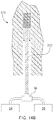
- the resin and catalyst will mix as it flows through the injection tube 222.
- a grout tube 224 may be attached to the mine roof bolt and remain in the cured resin/catalyst mixture.
- the mine roof bolt may be installed after injection of the resin and catalyst as described above in connection with the system of Fig. 14B .
- the method of installing the system 220 of Fig. 14C typically includes: drilling the borehole; connecting the injection line 222 to the grout tube 224 which lays alongside the mine roof bolt (not shown) or inserting the injection line 222 into the end of the borehole; pumping a predetermined amount of resin and catalyst into the borehole at a turbulent flow rate to allow mixing of the resin and catalyst; and stopping the pumping when the borehole is full.
- the mine roof bolt will be completely installed and no spinning of the mine roof bolt will be necessary due to the turbulent flow and prior mixing of the resin and catalyst.
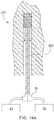
- a system 230 utilizes a single injection line 232 and creates a point anchored arrangement.
- the typical size of the injection line 232 is 0.01905 m (3 ⁇ 4") for a 33 mm borehole.
- the resin and catalyst are pumped into the Wye at a fast rate to create turbulent (mixing) flow then at a predetermined position, the flow is switched to a laminar (non-mixing) flow.
- the mixed resin/catalyst at a top section 234 of the borehole starts to react where the resin and catalyst at a bottom portion 236 of the borehole does not react or setup.
- a mine roof bolt (not shown) is quickly installed and spun to mix the bottom section 236 starting the reaction time for the mixed resin and catalyst.
- the top section 234, which was mixed during injection, will set before the bottom section 236 to allow the bolt to be torqued thereby creating tension in the bolt before the bottom section 236 sets.
- the system 230 is similar to a point anchored rebar bolt that uses a fast resin/catalyst cartridge at the top and a slow resin/catalyst cartridge at the bottom.
- the method of installing the system of Fig. 14D typically includes: drilling the borehole; inserting the injection line 232 into the end of the borehole; pumping a predetermined about of resin and catalyst into the borehole at a turbulent flow rate to allow mixing of resin and catalyst; after a predetermined length of time or amount of resin and catalyst supplied at a turbulent flow rate, switching to a laminar flow rate of the resin and catalyst to prevent mixing; simultaneously with the turbulent and laminar flow rate pumping, retracting the injection line 232 at a set rate to prevent voids and flowback ahead of the injection line; and installing a mine roof bolt (not shown) and spinning the mine roof bolt to mix the resin and catalyst.
- the top section 234 of resin/catalyst injected with a turbulent flow rate, thereby mixing the resin and catalyst will set first to allow a drive member, such as a nut, at the bottom of the mine roof bolt to be torqued to the tension the mine roof bolt.
- the resin and catalyst cartridges 160, 162 may be fed into the cylinders 154, 156 by removing the cap 164.
- the cap 164 may be moveable relative to the cylinders 154, 156 via any suitable arrangement.
- the cap 164 may be hinged, laterally moveable using a gate valve-like arrangement, or may be vertically moveable with the cylinders 154, 156 being moveable via a sliding base.
- the resin and catalyst cartridges 160, 162 may be provided with various resin to catalyst ratios from about 1:1 to 95:5. In one aspect, the ratio may be about 2:1 with the resin and catalyst provided separately in the cartridges 160, 162.
- the cylinders 154, 156 include a port 166 extending through a sidewall of the cylinders 154, 156, although the port 166 may also be provided in the cap 164 as indicated by dashed lines in Figs. 15 and 16 .
- the port 166 may be a 0.01905 m (3 ⁇ 4") hose connection port, although other suitable connections and ports may be utilized.
- the cartridges 160, 162 include a body 168 that defines a space for receiving the resin or catalyst.
- the body 168 may be formed from a non-reactive plastic materials, such as Nylon, Polypropylene, or polytetrafluoroethylene-based material, although other suitable materials may be utilized.
- the resin cartridge 160 may be 0.1524 m (6") in diameter and the catalyst cartridge 162 may be 0.1016 m (4") in diameter with each cartridge 160, 162 having a height of 0.3556 m (14"), which corresponds to the size of the cylinders 154, 156, although suitable sizes may be utilized.
- the cap 164 and the cylinders 154, 156 define a gap 170 between the cap 164 and the cylinders 154, 156.
- the gap 170 allows air to escape from within the cylinders 154, 156 during the initial compression of the cartridges 160, 162 within the cylinders 154, 156. If the lid 164 forms an air-tight seal with the cylinders 154, 156, air would become trapped within the cylinders 154, 156 and would eventually be forced out through the grout tube 66 causing undesirable air bursts or pops, uneven flow, and/or turbulent mixing of the resin and catalyst. As shown in Fig.
- the air will escape through the gap 170 with the body 168 of the cartridges 160, 162 expanding to self-seal the gap 170 between cap 164 and the cylinders 154, 156.
- the cap 164 and cylinders 154, 156 form a self-sealing design where resin and catalyst does not escape through the gap 170 and where the plastic bag does not break or extrude through the gap 170.
- the body 168 of the cartridges 160, 162 will only be punctured at the location of the port 166 and flow directly into the port 166 for eventual delivery to the borehole.
Landscapes
- Engineering & Computer Science (AREA)
- Mining & Mineral Resources (AREA)
- Structural Engineering (AREA)
- Life Sciences & Earth Sciences (AREA)
- General Life Sciences & Earth Sciences (AREA)
- Geochemistry & Mineralogy (AREA)
- Geology (AREA)
- Consolidation Of Soil By Introduction Of Solidifying Substances Into Soil (AREA)
- Excavating Of Shafts Or Tunnels (AREA)
- Processing And Handling Of Plastics And Other Materials For Molding In General (AREA)
- Feeding, Discharge, Calcimining, Fusing, And Gas-Generation Devices (AREA)
- Adhesives Or Adhesive Processes (AREA)
Description
- This application claims priority to United States Provisional Application Serial Nos.
62/127,450 62/286,686, filed March 3, 2015 - The present invention relates to a two component resin and, more particularly, to a pumpable two component resin system and method for the installation of mine roof bolts.
- The roof of a mine is conventionally supported by tensioning the roof with steel bolts inserted into boreholes drilled in the mine roof that reinforce the unsupported rock formation above the mine roof. The mine roof bolt may be anchored mechanically to the rock formation by engagement of an expansion assembly on the distal end of the mine roof bolt with the rock formation. Alternatively, the mine roof bolt may be adhesively bonded to the rock formation with a resin bonding material inserted into the borehole. A combination of mechanical anchoring and resin bonding may also be employed by using both an expansion assembly and resin bonding material.
- When resin bonding material is utilized, the bonding material penetrates the surrounding rock formation to adhesively join the rock strata and to firmly hold the roof bolt within the borehole. Resin is typically inserted into the mine roof borehole in the form of a two component plastic cartridge having one component containing a curable resin composition and another component containing a curing agent (catalyst). The two component resin cartridge is inserted into the blind end of the borehole and the mine roof bolt is inserted into the borehole such that the end of the mine roof bolt ruptures the two component resin cartridge. Upon rotation of the mine roof bolt about its longitudinal axis, the compartments within the resin cartridge are shredded and the components are mixed. The resin mixture fills the annular area between the borehole wall and the shaft of the mine roof bolt. The mixed resin cures and binds the mine roof bolt to the surrounding rock. The mine roof bolt is typically rotated via a drive head.
US 2014/0140773 A1 discloses a resin injection apparatus for use in connection with a drilling apparatus. The apparatus includes fluid containers for the resin and catalyst with each having a separate pump.WO 2014/190382 A1 is directed to a self-drilling rock bolt assembly including reservoirs, priming pumps, displacement pumps and an injection nozzle.US 2007/0264088 A1 discloses a system for embedding rock anchors including a drill rod, feed pumps and drive motors, reservoirs and a control device. - In one aspect, a pumpable resin system for installation of mine roof bolts comprisesa resin reservoir configured to receive resin, a catalyst reservoir configured to receive catalyst, a resin pump arrangement in fluid communication with the resin reservoir, a catalyst pump arrangement in fluid communication with the catalyst reservoir, a delivery line in fluid communication with at least one of the resin pump arrangement and the catalyst pump arrangement, and a bolter arm configured to drill boreholes and install mine roof bolts. The delivery line is configured to deliver resin and catalyst from the resin reservoir and the catalyst reservoir to a borehole via the bolter arm. The resin reservoir comprises a resin feed cylinder configured to receive a resin cartridge and the catalyst reservoir comprises a catalyst feed cylinder configured to receive a catalyst cartridge. The resin feed cylinder and the catalyst feed cylinder each comprise a cap, the cap of the resin feed cylinder defining a gap between the cap of the resin feed cylinder and the resin feed cylinder, and the cap of the catalyst feed cylinder defining a gap between the cap of the catalyst feed cylinder and the catalyst feed cylinder. The gaps are configured to allow air to escape the respective resin feed cylinder and the catalyst feed cylinder during compression of resin and catalyst cartridges within the respective resin feed cylinder and the catalyst feed cylinder.
- The delivery line may include a resin line in fluid communication with the resin pump arrangement and a catalyst line in fluid communication with the catalyst pump arrangement. The resin line and the catalyst line may be received by a static mixer, with the delivery further including a grout tube is in fluid communication with the static mixer and configured to deliver a resin/catalyst mix into a borehole. The system may further include an inhibitor reservoir, an inhibitor pump arrangement, and an inhibitor line in fluid communication with the inhibitor pump arrangement, with the inhibitor line configured to deliver inhibitor from the inhibitor reservoir to the borehole to define a fast set section and a slow set section within a borehole. The resin pump arrangement may include a resin cylinder pump and the catalyst pump arrangement may include a catalyst cylinder pump, with the resin cylinder pump and the catalyst cylinder pump are slaved together and controlled by a hydraulic piston and hydraulic pump.
- In a further aspect, a method of installing a mine roof bolt includessupplying resin from the resin feed cylinder to the resin line via the resin cylinder pump, supplying catalyst from the catalyst feed cylinder to the catalyst line via the catalyst cylinder pump, injecting resin and catalyst through the resin and catalyst lines into a borehole and installing a mine roof bolt in the borehole using a bolter arm .
- The method may include actuating a hydraulic piston to supply the resin and catalyst to the resin and catalyst lines. The method may also include supplying an inhibitor from an inhibitor reservoir to the borehole, with the inhibitor configured to react slower with the resin than the catalyst reacts with the resin to define a fast set section and a slow set section within the borehole. The inhibitor may be supplied from the inhibitor reservoir via an inhibitor pump arrangement and an inhibitor line in fluid communication with the inhibitor pump arrangement. The resin line and the catalyst line may be received by a static mixer with a grout tube being in fluid communication with the static mixer. The grout tube may be secured to the bolter arm and moveable relative to the bolter arm.
- These and other features and characteristics of the system will become more apparent upon consideration of the following description with reference to the accompanying drawings, all of which form a part of this specification, wherein like reference numerals designate corresponding parts in the various figures. It is to be expressly understood, however, that the drawings are for the purposes of illustration and description only and are not intended as a definition of the limits of the invention. As used in the specification, the singular form of "a", "an", and "the" include plural referents unless the context clearly dictates otherwise.
-
-
Fig. 1 is an elevational view of a pumping system and method for installing a mine roof bolt according to one aspect of the invention showing the filling of a borehole. -
Fig. 2 is an elevational view of the system and method ofFig. 1 showing a mine roof bolt being inserted into a borehole. -
Fig. 3 is an elevational view of the system and method ofFig. 1 showing the mine roof bolt installed. -
Fig. 4 is an elevational view of a pumping system and method for installing a mine roof bolt according to a second aspect of the invention. -
Fig. 5 is an elevational view of a pumping system and method for installing a mine roof bolt according to a third aspect of the invention. -
Fig. 6 is an elevational view of a pumping system and method for installing a mine roof bolt according to a fourth aspect of the invention showing the initial filling of the borehole. -
Fig. 7 is an elevational view of the system and method ofFig. 6 showing the borehole filled with a resin and a catalyst. -
Fig. 8 is an elevational view of a pumping system and method for installing a mine roof bolt according to a fifth aspect of the invention. -
Fig. 9 is an elevational view of a pumping system and method for installing a mine roof bolt according to a sixth aspect of the invention. -
Fig. 10 is an elevational view of a pumping system and method for installing a mine roof bolt according to a seventh aspect of the invention. -
Fig. 11 is a perspective view of a twin auger arrangement for a hopper according to one aspect of the invention. -
Figs. 12A-12D are elevational views showing a method of installing a mine roof bolt according to one aspect of the invention. -
Fig. 13 is an elevational view of a pumping system and method for installing a mine roof bolt according to a further aspect of the invention. -
Figs. 14A-D are elevational views showing various methods of installing a mine roof bolt according to one aspect of the invention. -
Fig. 15 is a partial cross-sectional view of a pumping arrangement according to one aspect of the invention, showing an initial position of the pumping arrangement. -
Fig. 16 is a partial cross-sectional view of a pumping arrangement according to one aspect of the invention, showing a pumping position of the pumping arrangement. - Aspects of the present invention will now be described with reference to the accompanying figures. For purposes of the description hereinafter, the terms "upper", "lower", "right", "left", "vertical", "horizontal", "top", "bottom", and derivatives thereof shall relate to the invention as it is oriented in the drawing figures. However, it is to be understood that the invention may assume various alternative variations and step sequences, except where expressly specified to the contrary. It is to be understood that the specific apparatus illustrated in the attached figures and described in the following specification is simply an exemplary aspect of the present invention. Hence, specific dimensions and other physical characteristics related to the aspects disclosed herein are not to be considered as limiting.
- Referring to
Figs. 1-3 , one aspect of a pumpable twocomponent resin system 10 includes a delivery line formed by aresin line 12 and acatalyst line 14 that are configured to deliver grout, such as aresin 28 and acatalyst 30 to a borehole. Theresin line 12 and thecatalyst line 14 each have aninlet outlet inlet 16 of theresin line 12 is connected to and in fluid communication with aresin pump 24. Theinlet 20 of thecatalyst line 14 is connected to and in fluid communication with acatalyst pump 26. Theresin pump 24 and the catalyst pump 26 are connected to respective reservoirs (not shown) containingresin 28 andcatalyst 30. Theresin line 12 and thecatalyst line 14 may be secured to each other viabands 32 to aid the insertion of thelines borehole 34. The resin and catalyst pumps 24, 26 may be chop check pumps, although other types of pumps suitable for pumping material of a high viscosity may also be utilized. The flow of eachpump resin 28 and thecatalyst 30, which is preferably 2:1 or 66% resin and 33% catalyst using a water-based catalyst. The ratio can range from about 4:1 to 3:2. With an oil-based catalyst, a 9:1 +/- 5% ratio is utilized. The flow of eachpump outlets resin line 12 and thecatalyst line 14. Theresin 28 is a filled resin having 10-25% inert filler, such as limestone. The resin may have a viscosity of about 100,000-400,000 centipoise. Conventional polyurethane resin typically has a viscosity of less than 10,000 centipoise. The use of a high viscosity resin generally makes pumping more difficult, but provides significant cost savings through the use of the less expensive filler. - Referring to
Fig. 1 , to start the filling of theborehole 34, the resin andcatalyst lines borehole 34 and thepumps resin 28 andcatalyst 30. As theresin 28 andcatalyst 30 are pumped into theborehole 34, thelines borehole 34. Alternatively, a packer or plug (not shown) slightly smaller than the inner diameter of the borehole 34 may be installed just before the end of thelines - Referring to
Figs. 2 and3 , theresin 28 and thecatalyst 30 will contact each other and will react to create a very fine barrier, which will prevent further reaction from occurring between theresin 28 and thecatalyst 30. Amine roof bolt 36 is then inserted into theborehole 34 and rotated to mix theresin 28 andcatalyst 30. After themine roof bolt 36 has been fully inserted, as shown inFig. 3 , themixed resin 28 andcatalyst 30 hardens and cures to securely anchor thebolt 36 within theborehole 34. - Referring to
Fig. 4 , the pumpable twocomponent resin system 10 may further include aconnector 38, such as a wye or T connector, for receiving theresin line 12 and thecatalyst line 14 from theresin pump 24 and thecatalyst pump 26, respectively. The use of theconnector 38 allows the resin andcatalyst lines single grout tube 39 that is connected to theresin pump 24 and catalyst pump 26 through theconnector 38. Thesingle grout tube 39 acts as a delivery line and configured to introduce theresin 28 andcatalyst 30 into theborehole 34. Thesystem 10 using theconnector 38 would operate in the same manner as described above in connection withFigs. 1-3 . - Referring to
Fig. 5 , a third aspect of a pumpable twocomponent resin system 40 includes aresin line 42 and acatalyst line 44. Theresin line 42 and thecatalyst line 44 each have aninlet outlet inlets resin line 42 and thecatalyst line 44 are connected to and in fluid communication with aresin pump 56 and acatalyst pump 58, respectively, in a similar manner as shown inFig. 1 and discussed above. Theoutlets resin line 42 and thecatalyst line 44, however, are connected to aconnector 60, such as a wye or T fitting, which is secured to astatic mixer 62. Thestatic mixer 62 is configured to mix theresin 28 andcatalyst 30 prior to being pumped into aborehole 64. Asingle grout tube 66 acts as a delivery line and is secured to thestatic mixer 62 and configured to introduce the resin and catalyst as a mixture into theborehole 64. - Referring to
Figs. 6 and7 , a fourth aspect of a pumpable twocomponent resin system 70 includes a delivery line formed by aresin line 72, astandard catalyst line 74, and aninhibited catalyst line 76. Thesystem 70 ofFigs. 6 and7 operates in a similar manner to thesystem 10 shown inFig. 1 and described above, but includes the inhibitedcatalyst line 76 to provide within the borehole 34 a fast set section 78 (such as at the blind end of the borehole 34) and a slow set section 79 (further spaced from the blind end of the borehole 34). Inhibited catalyst orinhibitor 77 reacts more slowly with the resin from theresin line 72 than thestandard catalyst 30 from thestandard catalyst line 74 reacts with theresin 28 from theresin line 72. The sections allow a mine roof bolt to be anchored at the fast set section and subsequently tensioned while the slow set section is still curing. - Referring again to
Figs. 6 and7 , in use, thelines borehole 34. Theresin line 72 and thestandard catalyst line 74 may then be activated or placed in the "ON" state as shown inFig. 6 such that theresin 28 andstandard catalyst 30 are delivered to the borehole 34 with the inhibitedcatalyst line 74 placed in the "OFF" state. Theresin 28 andstandard catalyst 30 are provided along a predetermined length of the borehole 34 to define thefast set section 78. At that point, thestandard catalyst line 74 is deactivated or placed in the "OFF" state and theinhibited catalyst line 76 is placed in the "ON" state such thatresin 28 and inhibitedcatalyst 30 are provided along a predetermined length of the borehole to define theslow set section 79. Thefast set section 78 ofresin 28 andcatalyst 30 will harden and set up faster than theslow set section 79 due to differences between thecatalyst 30 provided by thestandard catalyst line 74 and theinhibited catalyst line 76, which allows a mine roof bolt to be installed and point anchored at the blind end of theborehole 34 and subsequently tensioned while theslow set section 79 is still curing. - Referring to
Fig. 8 , a fifth aspect of a pumpable twocomponent resin system 80 includes aresin line 82, astandard catalyst line 84, and acatalyst inhibitor line 86. Thesystem 80 ofFig. 8 is similar to the system shown inFigs. 6 and7 and described above, but feeds thecatalyst inhibitor line 86 directly to thestandard catalyst line 84. Thecatalyst inhibitor line 86 would only be operated or pumped at the sections where a slower set time is desired. Connecting thecatalyst inhibitor line 86 to thestandard catalyst line 84 prevents the need for a third line positioned within theborehole 34. Thissystem 80 could also be utilized by pre-mixing the resin and the catalyst. Thesystem 80 may also utilize two or more resin compositions in addition to using two or more catalysts. In particular, thesystem 80 may utilize a plurality of resins and catalysts to optimize their performance and cost. - Referring to
Fig. 9 , a sixth aspect of a pumpable twocomponent resin system 90 includes aresin line 92 and acatalyst line 94. Theresin line 92 and thecatalyst line 94 each have aninlet outlet inlet 96 of theresin line 92 is connected to and in fluid communication with aresin cylinder pump 106. Theinlet 102 of thecatalyst line 94 is connected to and in fluid communication with acatalyst cylinder pump 108. Theoutlets grout tube 66 acting as a delivery line, although other suitable arrangements may be utilized. Theresin cylinder pump 106 and thecatalyst cylinder pump 108 are connected to respective supply pumps 110, 112 via aresin supply line 114 and acatalyst supply line 116. The supply pumps 110, 112pump resin 126 andcatalyst 128 fromrespective reservoirs resin supply line 114 andcatalyst supply line 116 and into the respectiveresin cylinder pump 106 andcatalyst cylinder pump 108. As shown inFig. 9 , theresin cylinder pump 106 and thecatalyst cylinder pump 108 are slaved together to inject theresin 126 andcatalyst 128 at about a constant 2:1 volumetric ratio, although other suitable ratios may be utilized. The slaved pumps 106, 108 are controlled by aseparate piston 113, which is operated by ahydraulic pump 115. Thehydraulic pump 115 may have a maximum output pressure of 8.274∗106 Pa (1,200 psi), which has been demonstrated to be effective in injectingresin 126 andcatalyst 128 into a borehole 130 through a 0.0127 m (½") diameter tube over 15.24 m (50 feet) in length, although other suitable pumps may be utilized. - The supply pumps 110, 112 are diaphragm pumps, although other types of pumps suitable for pumping material of a high viscosity may also be utilized, such as chop check pumps, progressive cavity pumps, etc. The pumpable two
component resin system 90 shown inFig. 9 generally operates in the same manner as thesystem 10 shown inFigs. 1-3 and discussed above. The supply pumps 110, 112 are used to fillrespective cylinders resin cylinder pump 106 andcatalyst cylinder pump 108 to a predetermined level for each of thecylinders resin cylinder pump 106 and thecatalyst cylinder pump 108 are then activated to dispenseresin 126 andcatalyst 128 simultaneously. In order to obtain the desirable resin to catalyst ratio, theresin cylinder 122 should generally be about two times larger in volume relative to thecatalyst cylinder 124. In a similar manner as shown inFigs. 2 and3 , theresin 126 andcatalyst 128 will fill theborehole 130 and then a bolt is subsequently inserted into theborehole 130. Theresin cylinder pump 106 and thecatalyst cylinder pump 108 may then be recharged via the supply pumps 110, 112. Thereservoirs twin auger arrangement 132, which is shown more clearly inFig. 11 , although other suitable reservoir arrangements may be utilized. Thetwin auger arrangement 132 allows the components to be continuously mixed to prevent separation or drying out of the resin andcatalyst reservoirs cartridges 139 or other containers containing the resin andcatalyst grout tube 66 is connected to abolter arm 140 and is moveable relative to thebolter arm 140 to allow the insertion of thegrout tube 66 within theborehole 130 for delivery of the grout. The system shown inFig. 9 may utilize any other arrangements shown inFigs. 1-8 and described above. - Referring to
Fig. 10 , the pumpable twocomponent resin system 90 shown inFig. 9 and described above may utilize progressive cavity pumps for the supply pumps 110, 112 rather than the diaphragm pumps shown inFig. 9 . Thesystem 90, however, would operate in the same manner as described above. - Referring to
Figs. 12A-12D , one aspect of amethod 134 for installing a mine roof bolt is shown. Themethod 134 may provide an automated arrangement for injecting and installing a mine roof bolt using a bolting machine (not shown). After drilling a borehole 136 using a bolting machine, agrout tube 138 is inserted into the borehole 136 using thebolter arm 140 of the bolting machine as shown inFig. 12A . Resin andcatalyst components borehole 136 and thegrout tube 138 is retracted at a suitable rate to prevent air pockets or the flow of resin andcatalyst grout tube 138 as shown inFigs. 12B and12C . Once the required amount of resin andcatalyst borehole 136, thegrout tube 138 is removed from the borehole 136 as shown inFig. 12D . A mine roof bolt may be subsequently inserted into theborehole 136 and rotated to mine the resin andcatalyst Figs. 1-3 . Further, the method shown inFigs. 12A-12D may utilize any of the systems and arrangements shown inFigs. 1-11 . The bolting machine may be configured to automatically drill theborehole 136, inject the resin andcatalyst borehole 136, and install a mine roof bolt by inserting the bolt into theborehole 136 and rotating the bolt to mix the resin andcatalyst grout tube 138 may be driven by a first and second set ofdrive wheels grout tube 138 may be utilized. - Referring to
Fig. 13 , a pumpable twocomponent resin system 150 is similar to thesystem 90 shown inFig. 9 and discussed above. However, rather than utilizing supply pumps 110, 112 as in thesystem 90 ofFig. 9 , thesystem 150 ofFig. 13 utilizes afeed pump arrangement 152 having aresin feed cylinder 154 and acatalyst feed cylinder 156 that are slaved together to feed theresin cylinder pump 106 andcatalyst cylinder pump 108, respectively. Thecylinders main piston 158, which is operated by a hydraulic pump (not shown). Theresin feed cylinder 154 andcatalyst feed cylinder 156 may be supplied with resin andcatalyst cartridges catalyst cartridges cylinders cap 164, which is discussed in more detail below and shown inFigs. 15 and 16 . - Referring to
Figs. 14A-14D , further methods of installing a mine roof bolt using thesystems systems - Referring to
Fig. 14A , asystem 200 uses a dividedinjection tube 202 in order to keep the two components separate. When the resin and catalyst exit the injection tube they will lay side by side in the borehole. Turbulent and laminar flow is not an issue with thissystem 200 and method. The method of using thissystem 200 typically includes: drilling the borehole; inserting theinjection tube 202 into the borehole; pumping resin and catalyst at any flow rate to prevent mixing; simultaneously with pumping the resin and catalyst, retracting theinjection tube 202 at a set rate to prevent voids and flowback ahead of theinjection tube 202; and installing a mine roof bolt (not shown) and spinning the mine roof bolt to mix the resin and catalyst. Typical properties for this method are below:Resin Viscosity: 125,000 - 225,000 cps Catalyst Viscosity: 10,000 - 25,000 cps Injection Line ID: 0.01905 m (¾") Injection Line Length: 4.2672 m (14') Flow Rate: 6.309∗10-5 m3/s - 18.927∗ 10-5 m3/s (1 - 3 gpm) - Referring to
Fig. 14B , asystem 210 utilizes asingle injection line 212. The typical size of theinjection line 212 is 0.01905 m (¾") for a 33 mm borehole. The resin and catalyst are pumped into the Wye at a slower rate in order to keep the flow laminar. The resin and catalyst will lay side by side with minuscule mixing. As the resin and catalyst exits theinjection line 212, the resin and catalyst will remain side by side in the borehole. The mine roof bolt is then inserted into the separated resin and catalyst and rotated to mix resin and catalyst. Typical properties for this method are below:Resin Viscosity: 200,000 - 225,000 cps Catalyst Viscosity: 20,000 - 25,000 cps Injection Line ID: 0.01905 m (¾") Injection Line Length: 4.2672 m (14') Flow Rate: 6.309∗10-5 m3/s - 9.4635∗ 10-5 m3/s (1 - 1.5 gpm) - With the method of using the
system 210 ofFig. 14B , if the flow rate is increased from laminar flow to an intermediate flow rate, minor mixing will occur in theinjection line 212. This flow rate is about 9.4635∗10-5 m3/s (1.5 gpm). The minor mixing of the resin and catalyst will cause small hardened flakes of mixed resin and catalyst 0.003175 m (⅛") wide by 0.0127 m (½") in length by 0.0015875 m (1/16") thick to form within the raw resin and catalyst as the resin and catalyst are injected. Approximately only 10% of the resin may react with the catalyst during this partial mixing process. The reacted pieces of resin/catalyst act as small mixing blades when a mine roof bolt is installed. - The method of using this
system 210 typically includes: drilling the borehole; inserting theinjection line 212 into the borehole; pumping resin and catalyst at a laminar flow rate to prevent mixing; simultaneously with pumping, retracting theinjection line 212 at a set rate to prevent voids and flowback ahead of theinjection line 212; and installing a mine roof bolt (not shown) and spinning the bolt to mix the resin and catalyst. - Referring to
Fig. 14C , asystem 220 uses asingle injection line 222. The typical size of theinjection line 222 is 0.01905 m (¾"). The resin and catalyst are pumped into the Wye at a faster rate to create an intermediate to turbulent flow. The resin and catalyst will mix as it flows through theinjection tube 222. In one aspect of this method, agrout tube 224 may be attached to the mine roof bolt and remain in the cured resin/catalyst mixture. However, in other aspects, the mine roof bolt may be installed after injection of the resin and catalyst as described above in connection with the system ofFig. 14B . Typical properties for this method are below:Resin Viscosity: 125,000 - 150,000 cps Catalyst Viscosity: 10,000 - 15,000 cps Injection Line ID: 0.01905 m (¾") Injection Line Length: 4.2672 m (14') Flow Rate: 12.618∗10-5 m3/s - 15.7725∗10-5 m3/s (2.0 - 2.5 gpm) - The method of installing the
system 220 ofFig. 14C typically includes: drilling the borehole; connecting theinjection line 222 to thegrout tube 224 which lays alongside the mine roof bolt (not shown) or inserting theinjection line 222 into the end of the borehole; pumping a predetermined amount of resin and catalyst into the borehole at a turbulent flow rate to allow mixing of the resin and catalyst; and stopping the pumping when the borehole is full. The mine roof bolt will be completely installed and no spinning of the mine roof bolt will be necessary due to the turbulent flow and prior mixing of the resin and catalyst. - Referring to
Fig. 14D , asystem 230 utilizes asingle injection line 232 and creates a point anchored arrangement. The typical size of theinjection line 232 is 0.01905 m (¾") for a 33 mm borehole. At the start of injection, the resin and catalyst are pumped into the Wye at a fast rate to create turbulent (mixing) flow then at a predetermined position, the flow is switched to a laminar (non-mixing) flow. The mixed resin/catalyst at atop section 234 of the borehole starts to react where the resin and catalyst at abottom portion 236 of the borehole does not react or setup. A mine roof bolt (not shown) is quickly installed and spun to mix thebottom section 236 starting the reaction time for the mixed resin and catalyst. Thetop section 234, which was mixed during injection, will set before thebottom section 236 to allow the bolt to be torqued thereby creating tension in the bolt before thebottom section 236 sets. Thesystem 230 is similar to a point anchored rebar bolt that uses a fast resin/catalyst cartridge at the top and a slow resin/catalyst cartridge at the bottom. Typical properties for this method are below:Resin Viscosity: 125,000 - 225,000 cps Catalyst Viscosity: 10,000 - 25,000 cps Injection Line ID: 0.01905 m (¾") Injection Line Length: 4.2672 m (14') Flow Rate: 6.309∗10-5 m3/s - 15.7725∗ 10-5 m3/s (1 - 2.5 gpm) - The method of installing the system of
Fig. 14D typically includes: drilling the borehole; inserting theinjection line 232 into the end of the borehole; pumping a predetermined about of resin and catalyst into the borehole at a turbulent flow rate to allow mixing of resin and catalyst; after a predetermined length of time or amount of resin and catalyst supplied at a turbulent flow rate, switching to a laminar flow rate of the resin and catalyst to prevent mixing; simultaneously with the turbulent and laminar flow rate pumping, retracting theinjection line 232 at a set rate to prevent voids and flowback ahead of the injection line; and installing a mine roof bolt (not shown) and spinning the mine roof bolt to mix the resin and catalyst. As noted above, thetop section 234 of resin/catalyst injected with a turbulent flow rate, thereby mixing the resin and catalyst, will set first to allow a drive member, such as a nut, at the bottom of the mine roof bolt to be torqued to the tension the mine roof bolt. - Referring to
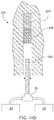
Figs. 15 and 16 , the resin andcatalyst cartridges cylinders cap 164. Thecap 164 may be moveable relative to thecylinders cap 164 may be hinged, laterally moveable using a gate valve-like arrangement, or may be vertically moveable with thecylinders catalyst cartridges cartridges cylinders port 166 extending through a sidewall of thecylinders port 166 may also be provided in thecap 164 as indicated by dashed lines inFigs. 15 and 16 . Theport 166 may be a 0.01905 m (¾") hose connection port, although other suitable connections and ports may be utilized. Thecartridges body 168 that defines a space for receiving the resin or catalyst. Thebody 168 may be formed from a non-reactive plastic materials, such as Nylon, Polypropylene, or polytetrafluoroethylene-based material, although other suitable materials may be utilized. Theresin cartridge 160 may be 0.1524 m (6") in diameter and thecatalyst cartridge 162 may be 0.1016 m (4") in diameter with eachcartridge cylinders - Referring again to
Figs. 15 and 16 , thecap 164 and thecylinders gap 170 between thecap 164 and thecylinders gap 170 allows air to escape from within thecylinders cartridges cylinders lid 164 forms an air-tight seal with thecylinders cylinders grout tube 66 causing undesirable air bursts or pops, uneven flow, and/or turbulent mixing of the resin and catalyst. As shown inFig. 16 , when thecartridges gap 170 with thebody 168 of thecartridges gap 170 betweencap 164 and thecylinders cap 164 andcylinders gap 170 and where the plastic bag does not break or extrude through thegap 170. Further, when thecartridges body 168 of thecartridges port 166 and flow directly into theport 166 for eventual delivery to the borehole. When thecylinders body 168 of thecartridges body 168 of thecartridges cylinders full cartridges cylinders cartridges cap 164 keeps thecylinders cylinders - While various aspects of the system were provided in the foregoing description, those skilled in the art may make modifications and alterations to these aspects or aspects without departing from the scope of the invention. For example, it is to be understood that this disclosure contemplates that, to the extent possible, one or more features of any aspect or aspect can be combined with one or more features of any other aspect or aspect. Accordingly, the foregoing description is intended to be illustrative rather than restrictive. The invention described hereinabove is defined by the specification, and all changes to the invention that fall within the meaning and the range of equivalency of the specification are to be embraced within its scope. The scope of protection of the current invention is solely defined by the appended claims.
Claims (10)
- A pumpable resin system (150) for installation of mine roof bolts comprising:a resin reservoir configured to receive resin;a catalyst reservoir configured to receive catalyst;a resin pump arrangement in fluid communication with the resin reservoir;a catalyst pump arrangement in fluid communication with the catalyst reservoir;a delivery line in fluid communication with at least one of the resin pump arrangement and the catalyst pump arrangement; anda bolter arm (140) configured to drill boreholes and install mine roof bolts, wherein the delivery line is configured to deliver resin and catalyst from the resin reservoir and the catalyst reservoir to a borehole via the bolter arm (140);wherein the resin reservoir comprises a resin feed cylinder (154) configured to receive a resin cartridge (160) and the catalyst reservoir comprises a catalyst feed cylinder (156) configured to receive a catalyst cartridge (162), the resin feed cylinder (154) and the catalyst feed cylinder (156) each comprise a cap (164), the cap (164) of the resin feed cylinder (154) defining a gap (170) between the cap (164) of the resin feed cylinder (154) and the resin feed cylinder (154), and the cap (164) of the catalyst feed cylinder (156) defining a gap (170) between the cap (164) of the catalyst feed cylinder (156) and the catalyst feed cylinder (156), andwherein the gaps (170) are configured to allow air to escape the respective resin feed cylinder (154) and the catalyst feed cylinder (156) during compression of resin and catalyst cartridges (160, 162) within the respective resin feed cylinder (154) and the catalyst feed cylinder (156).
- The system of claim 1, wherein the delivery line comprises a resin line (92) in fluid communication with the resin pump arrangement and a catalyst line (94) in fluid communication with the catalyst pump arrangement.
- The system of claim 2, wherein the resin line (92) and the catalyst line (94) are received by a static mixer (62), and wherein a grout tube (66) is in fluid communication with the static mixer (62), the grout tube (66) configured to deliver a resin/catalyst mix into a borehole (34).
- The system of claim 1, further comprising an inhibitor reservoir, an inhibitor pump arrangement, and an inhibitor line (76) in fluid communication with the inhibitor pump arrangement, the inhibitor line (76) configured to deliver inhibitor from the inhibitor reservoir to the borehole to define a fast set section (78) and a slow set section (79) within a borehole.
- The system of claim 1, wherein the resin pump arrangement comprises a resin cylinder pump (106) and the catalyst pump arrangement comprises a catalyst cylinder pump (108), and wherein the resin cylinder pump (106) and the catalyst cylinder pump (108) are slaved together and controlled by a hydraulic piston (113) and hydraulic pump (115).
- A method of installing a mine roof bolt using the system of any of claims 1-5, the method comprising:supplying resin from the resin feed cylinder (154) to the resin line (92) via the resin cylinder pump (106);supplying catalyst from the catalyst feed cylinder (156) to the catalyst line (94) via the catalyst cylinder pump (108);injecting resin and catalyst through the resin and catalyst lines (92, 94) into a borehole (34); andinstalling a mine roof bolt in the borehole (34) using a bolter arm (140).
- The method of claim 6, further comprising:
actuating a hydraulic piston (113) to supply the resin and catalyst to the resin and catalyst lines. - The method of claim 6, further comprising:
supplying an inhibitor from an inhibitor reservoir to the borehole (34), the inhibitor configured to react slower with the resin than the catalyst reacts with the resin to define a fast set section (78) and a slow set section (79) within the borehole (34). - The method of claim 8, wherein the inhibitor is supplied from the inhibitor reservoir via an inhibitor pump arrangement and an inhibitor line (79) in fluid communication with the inhibitor pump arrangement.
- The method of claim 6, wherein the resin line (42) and the catalyst line (44) are received by a static mixer (62), wherein a grout tube (66) is in fluid communication with the static mixer, and wherein the grout tube (66) is secured to the bolter arm (140) and moveable relative to the bolter arm (140).
Priority Applications (1)
| Application Number | Priority Date | Filing Date | Title |
|---|---|---|---|
| PL16759380T PL3265651T3 (en) | 2015-03-03 | 2016-03-02 | Pumpable two component resin |
Applications Claiming Priority (3)
| Application Number | Priority Date | Filing Date | Title |
|---|---|---|---|
| US201562127450P | 2015-03-03 | 2015-03-03 | |
| US201662286686P | 2016-01-25 | 2016-01-25 | |
| PCT/US2016/020347 WO2016141008A1 (en) | 2015-03-03 | 2016-03-02 | Pumpable two component resin |
Publications (3)
| Publication Number | Publication Date |
|---|---|
| EP3265651A1 EP3265651A1 (en) | 2018-01-10 |
| EP3265651A4 EP3265651A4 (en) | 2018-11-21 |
| EP3265651B1 true EP3265651B1 (en) | 2020-07-01 |
Family
ID=56848583
Family Applications (1)
| Application Number | Title | Priority Date | Filing Date |
|---|---|---|---|
| EP16759380.5A Active EP3265651B1 (en) | 2015-03-03 | 2016-03-02 | Pumpable two component resin |
Country Status (12)
| Country | Link |
|---|---|
| US (3) | US10487655B2 (en) |
| EP (1) | EP3265651B1 (en) |
| CN (1) | CN107429565B (en) |
| AU (1) | AU2016226313B2 (en) |
| BR (1) | BR112017018542B1 (en) |
| CA (2) | CA2937523C (en) |
| CL (1) | CL2017002210A1 (en) |
| PE (1) | PE20171507A1 (en) |
| PL (1) | PL3265651T3 (en) |
| RU (1) | RU2681171C1 (en) |
| WO (1) | WO2016141008A1 (en) |
| ZA (1) | ZA201705372B (en) |
Families Citing this family (8)
| Publication number | Priority date | Publication date | Assignee | Title |
|---|---|---|---|---|
| SE541882C2 (en) * | 2017-06-14 | 2020-01-02 | Epiroc Rock Drills Ab | Arrangement and method for rock reinforcement |
| SE541304C2 (en) * | 2017-10-27 | 2019-06-25 | Epiroc Rock Drills Ab | Method and system for ensuring the quality of a multi-component blend for rock reinforcement |
| US11156217B2 (en) * | 2017-11-10 | 2021-10-26 | J-Lok Co. | Hydraulic and control system for resin injection |
| CN108799039B (en) * | 2018-06-06 | 2023-06-30 | 徐州吉安矿业科技有限公司 | High-viscosity transfer pump device incapable of flowing slurry automatically |
| MX2021009778A (en) | 2019-02-13 | 2021-10-26 | Fci Holdings Delaware Inc | RESIN INJECTION TRUCK PLATFORM. |
| CN110316792B (en) * | 2019-07-31 | 2024-01-19 | 西安西热水务环保有限公司 | High-speed mixed bed water distribution device capable of preventing resin from flowing backwards |
| EP3901410B1 (en) * | 2020-04-23 | 2024-04-17 | Sandvik Mining and Construction Lyon SAS | Apparatus for resin injection, mining machine and method |
| CN115749885A (en) * | 2022-11-25 | 2023-03-07 | 安徽路源环保科技有限公司 | Mining pneumatic press-in device |
Family Cites Families (33)
| Publication number | Priority date | Publication date | Assignee | Title |
|---|---|---|---|---|
| US3920223A (en) * | 1973-07-05 | 1975-11-18 | Wallace F Krueger | Plural component mixing head |
| US4055051A (en) | 1976-01-08 | 1977-10-25 | The United States Of America As Represented By The Secretary Of The Interior | Unitary drill bit and roof bolt |
| US4229124A (en) | 1979-02-15 | 1980-10-21 | Joy Manufacturing Company | Automatic roof bolting system for mines |
| US4386877A (en) | 1979-03-28 | 1983-06-07 | Peabody Coal Company | Mine roof bolting |
| US4289095A (en) * | 1979-07-05 | 1981-09-15 | Scherr Ronald R | Preheater for aircraft engines |
| US4322183A (en) * | 1980-03-07 | 1982-03-30 | Armand Ciavatta | Friction rock stabilizer and installation lubricating cement apparatus and method |
| AU2457484A (en) * | 1983-02-18 | 1984-08-23 | E.I. Du Pont De Nemours And Company | Chemically anchoring a rock bolt |
| US4509903A (en) | 1983-10-18 | 1985-04-09 | Fram Jerry R | Catalyst slave pump |
| FI79597C (en) * | 1985-11-07 | 1990-01-10 | Tampella Oy Ab | FOERFARANDE OCH APPARAT FOER MATNING AV BETONG I ETT BORRHAOL VID BETONGBULTNING AV BERG. |
| FI874966A7 (en) * | 1987-11-11 | 1989-05-12 | Tampella Oy Ab | SAETT OCH ANLAEGGNING FOER UPPFYLLNING AV BORRHAOL. |
| SU1702082A1 (en) * | 1990-01-10 | 1991-12-30 | Среднеазиатский Научно-Исследовательский Институт Геологии И Минерального Сырья | Method for advance strengthening of roof rock of mine workings |
| US5342149A (en) * | 1992-08-31 | 1994-08-30 | Mccabe Brothers, Inc. | Long hole chemical grout injector system |
| AUPP955399A0 (en) * | 1999-03-31 | 1999-04-29 | Hydramatic Engineering Pty. Ltd. | Method and apparatus for insertion of rockbolts |
| US6955991B2 (en) * | 1999-11-01 | 2005-10-18 | Jetek, Inc. | Atmospheric process and system for controlled and rapid removal of polymers from high depth to width aspect ratio holes |
| RU2202042C2 (en) * | 2000-12-18 | 2003-04-10 | Ануфриев Виктор Евгеньевич | Cable anchor |
| US6824364B2 (en) | 2002-09-20 | 2004-11-30 | Rimcraft Technologies, Inc. | Master/slave pump assembly employing diaphragm pump |
| AU2005297473B2 (en) | 2004-10-21 | 2011-05-12 | Minova International Limited | Method for embedding rock anchors |
| ZA200700740B (en) * | 2006-01-31 | 2007-11-28 | Raytheon Utd Inc | Rock bolt with grout flow geometry |
| US20070194474A1 (en) * | 2006-02-23 | 2007-08-23 | Nagy Peter S | Injection molding press |
| DE102007008966A1 (en) | 2006-02-24 | 2007-09-06 | Friedr. Ischebeck Gmbh | Injection head for injection drilling anchors, has sink head, inclusive of outer part having two different supply connections, and inner part with rear connection for drilling drive and front connection for anchoring ring |
| WO2009079684A1 (en) | 2007-12-21 | 2009-07-02 | Alminco Pty Ltd | Self drilling rock bolting |
| DE102008006234A1 (en) | 2008-01-25 | 2009-07-30 | Friedr. Ischebeck Gmbh | injection head |
| US7775745B2 (en) | 2009-01-20 | 2010-08-17 | J-Lok Co. | Anchoring systems and methods of use thereof |
| KR101552988B1 (en) * | 2009-07-10 | 2015-09-14 | 엘지디스플레이 주식회사 | Driving circuit for liquid crystal display device and method for driving the same |
| DE102010063098A1 (en) * | 2010-12-15 | 2012-02-16 | Hilti Aktiengesellschaft | rock bolt |
| DE102011004023A1 (en) * | 2011-02-14 | 2012-08-16 | Hilti Aktiengesellschaft | rock Sacker |
| AU2012269719B2 (en) * | 2011-06-14 | 2016-03-17 | Geobrugg Ag | Resin injection apparatus for drilling apparatus for installing a ground anchor |
| WO2013170312A1 (en) | 2012-05-17 | 2013-11-21 | Peter Andrew Gray | Injection and drive arrangement for rock bolting |
| CN102996388A (en) * | 2012-10-31 | 2013-03-27 | 镇江宝城注浆设备有限公司 | Dual-liquid synchronous grouting pump |
| CN202883286U (en) | 2012-10-31 | 2013-04-17 | 镇江宝城注浆设备有限公司 | Double-liquid synchronous grouting pump |
| US9499951B2 (en) * | 2013-05-27 | 2016-11-22 | Oka Rock Bolt Technologies Pty Limited | Self-drilling rock bolt assembly and method of installation |
| US9648865B2 (en) | 2013-05-30 | 2017-05-16 | Seachange Technology Holdings Pty Ltd | Chondrichthyan repelling system |
| CN103629067B (en) * | 2013-12-09 | 2015-12-16 | 镇江市博林光电科技有限公司 | Many pump heads synchronously inject proportioning regulating plunger pump |
-
2016
- 2016-03-02 CN CN201680012757.XA patent/CN107429565B/en active Active
- 2016-03-02 US US15/549,463 patent/US10487655B2/en active Active
- 2016-03-02 EP EP16759380.5A patent/EP3265651B1/en active Active
- 2016-03-02 BR BR112017018542-3A patent/BR112017018542B1/en active IP Right Grant
- 2016-03-02 CA CA2937523A patent/CA2937523C/en active Active
- 2016-03-02 PL PL16759380T patent/PL3265651T3/en unknown
- 2016-03-02 AU AU2016226313A patent/AU2016226313B2/en active Active
- 2016-03-02 RU RU2017134046A patent/RU2681171C1/en not_active IP Right Cessation
- 2016-03-02 PE PE2017001486A patent/PE20171507A1/en unknown
- 2016-03-02 CA CA3023649A patent/CA3023649C/en active Active
- 2016-03-02 WO PCT/US2016/020347 patent/WO2016141008A1/en not_active Ceased
-
2017
- 2017-08-08 ZA ZA2017/05372A patent/ZA201705372B/en unknown
- 2017-09-01 CL CL2017002210A patent/CL2017002210A1/en unknown
-
2019
- 2019-09-26 US US16/583,825 patent/US10954787B2/en active Active
-
2021
- 2021-03-18 US US17/205,771 patent/US11506055B2/en active Active
Non-Patent Citations (1)
| Title |
|---|
| None * |
Also Published As
| Publication number | Publication date |
|---|---|
| CL2017002210A1 (en) | 2018-05-18 |
| PE20171507A1 (en) | 2017-10-20 |
| AU2016226313B2 (en) | 2019-04-04 |
| US10487655B2 (en) | 2019-11-26 |
| US20210207480A1 (en) | 2021-07-08 |
| US20180030831A1 (en) | 2018-02-01 |
| US20200018165A1 (en) | 2020-01-16 |
| CA2937523A1 (en) | 2016-09-03 |
| EP3265651A1 (en) | 2018-01-10 |
| CA3023649C (en) | 2022-05-03 |
| CN107429565B (en) | 2020-07-14 |
| BR112017018542B1 (en) | 2022-08-09 |
| US11506055B2 (en) | 2022-11-22 |
| BR112017018542A2 (en) | 2018-04-24 |
| CA3023649A1 (en) | 2016-09-03 |
| AU2016226313A1 (en) | 2017-08-17 |
| CA2937523C (en) | 2019-01-08 |
| CN107429565A (en) | 2017-12-01 |
| EP3265651A4 (en) | 2018-11-21 |
| WO2016141008A1 (en) | 2016-09-09 |
| US10954787B2 (en) | 2021-03-23 |
| PL3265651T3 (en) | 2020-11-02 |
| RU2681171C1 (en) | 2019-03-04 |
| ZA201705372B (en) | 2019-05-29 |
Similar Documents
| Publication | Publication Date | Title |
|---|---|---|
| US11506055B2 (en) | Pumpable resin system | |
| US10669848B2 (en) | Pumpable resin system | |
| US11486380B2 (en) | Hydraulic and control system for resin injection |
Legal Events
| Date | Code | Title | Description |
|---|---|---|---|
| STAA | Information on the status of an ep patent application or granted ep patent |
Free format text: STATUS: THE INTERNATIONAL PUBLICATION HAS BEEN MADE |
|
| PUAI | Public reference made under article 153(3) epc to a published international application that has entered the european phase |
Free format text: ORIGINAL CODE: 0009012 |
|
| STAA | Information on the status of an ep patent application or granted ep patent |
Free format text: STATUS: REQUEST FOR EXAMINATION WAS MADE |
|
| 17P | Request for examination filed |
Effective date: 20170825 |
|
| AK | Designated contracting states |
Kind code of ref document: A1 Designated state(s): AL AT BE BG CH CY CZ DE DK EE ES FI FR GB GR HR HU IE IS IT LI LT LU LV MC MK MT NL NO PL PT RO RS SE SI SK SM TR |
|
| AX | Request for extension of the european patent |
Extension state: BA ME |
|
| DAV | Request for validation of the european patent (deleted) | ||
| A4 | Supplementary search report drawn up and despatched |
Effective date: 20181022 |
|
| RIC1 | Information provided on ipc code assigned before grant |
Ipc: E21D 20/02 20060101AFI20181016BHEP |
|
| STAA | Information on the status of an ep patent application or granted ep patent |
Free format text: STATUS: EXAMINATION IS IN PROGRESS |
|
| 17Q | First examination report despatched |
Effective date: 20190924 |
|
| GRAP | Despatch of communication of intention to grant a patent |
Free format text: ORIGINAL CODE: EPIDOSNIGR1 |
|
| STAA | Information on the status of an ep patent application or granted ep patent |
Free format text: STATUS: GRANT OF PATENT IS INTENDED |
|
| INTG | Intention to grant announced |
Effective date: 20200217 |
|
| GRAS | Grant fee paid |
Free format text: ORIGINAL CODE: EPIDOSNIGR3 |
|
| GRAA | (expected) grant |
Free format text: ORIGINAL CODE: 0009210 |
|
| STAA | Information on the status of an ep patent application or granted ep patent |
Free format text: STATUS: THE PATENT HAS BEEN GRANTED |
|
| AK | Designated contracting states |
Kind code of ref document: B1 Designated state(s): AL AT BE BG CH CY CZ DE DK EE ES FI FR GB GR HR HU IE IS IT LI LT LU LV MC MK MT NL NO PL PT RO RS SE SI SK SM TR |
|
| AX | Request for extension of the european patent |
Extension state: BA ME |
|
| REG | Reference to a national code |
Ref country code: CH Ref legal event code: EP Ref country code: AT Ref legal event code: REF Ref document number: 1286353 Country of ref document: AT Kind code of ref document: T Effective date: 20200715 |
|
| REG | Reference to a national code |
Ref country code: IE Ref legal event code: FG4D |
|
| REG | Reference to a national code |
Ref country code: DE Ref legal event code: R096 Ref document number: 602016039151 Country of ref document: DE Ref country code: FI Ref legal event code: FGE |
|
| REG | Reference to a national code |
Ref country code: SE Ref legal event code: TRGR |
|
| REG | Reference to a national code |
Ref country code: NO Ref legal event code: T2 Effective date: 20200701 |
|
| REG | Reference to a national code |
Ref country code: LT Ref legal event code: MG4D |
|
| PG25 | Lapsed in a contracting state [announced via postgrant information from national office to epo] |
Ref country code: BG Free format text: LAPSE BECAUSE OF FAILURE TO SUBMIT A TRANSLATION OF THE DESCRIPTION OR TO PAY THE FEE WITHIN THE PRESCRIBED TIME-LIMIT Effective date: 20201001 |
|
| REG | Reference to a national code |
Ref country code: NL Ref legal event code: MP Effective date: 20200701 |
|
| REG | Reference to a national code |
Ref country code: AT Ref legal event code: MK05 Ref document number: 1286353 Country of ref document: AT Kind code of ref document: T Effective date: 20200701 |
|
| PG25 | Lapsed in a contracting state [announced via postgrant information from national office to epo] |
Ref country code: GR Free format text: LAPSE BECAUSE OF FAILURE TO SUBMIT A TRANSLATION OF THE DESCRIPTION OR TO PAY THE FEE WITHIN THE PRESCRIBED TIME-LIMIT Effective date: 20201002 Ref country code: AT Free format text: LAPSE BECAUSE OF FAILURE TO SUBMIT A TRANSLATION OF THE DESCRIPTION OR TO PAY THE FEE WITHIN THE PRESCRIBED TIME-LIMIT Effective date: 20200701 Ref country code: PT Free format text: LAPSE BECAUSE OF FAILURE TO SUBMIT A TRANSLATION OF THE DESCRIPTION OR TO PAY THE FEE WITHIN THE PRESCRIBED TIME-LIMIT Effective date: 20201102 Ref country code: HR Free format text: LAPSE BECAUSE OF FAILURE TO SUBMIT A TRANSLATION OF THE DESCRIPTION OR TO PAY THE FEE WITHIN THE PRESCRIBED TIME-LIMIT Effective date: 20200701 Ref country code: LT Free format text: LAPSE BECAUSE OF FAILURE TO SUBMIT A TRANSLATION OF THE DESCRIPTION OR TO PAY THE FEE WITHIN THE PRESCRIBED TIME-LIMIT Effective date: 20200701 Ref country code: ES Free format text: LAPSE BECAUSE OF FAILURE TO SUBMIT A TRANSLATION OF THE DESCRIPTION OR TO PAY THE FEE WITHIN THE PRESCRIBED TIME-LIMIT Effective date: 20200701 |
|
| PG25 | Lapsed in a contracting state [announced via postgrant information from national office to epo] |
Ref country code: LV Free format text: LAPSE BECAUSE OF FAILURE TO SUBMIT A TRANSLATION OF THE DESCRIPTION OR TO PAY THE FEE WITHIN THE PRESCRIBED TIME-LIMIT Effective date: 20200701 Ref country code: RS Free format text: LAPSE BECAUSE OF FAILURE TO SUBMIT A TRANSLATION OF THE DESCRIPTION OR TO PAY THE FEE WITHIN THE PRESCRIBED TIME-LIMIT Effective date: 20200701 Ref country code: IS Free format text: LAPSE BECAUSE OF FAILURE TO SUBMIT A TRANSLATION OF THE DESCRIPTION OR TO PAY THE FEE WITHIN THE PRESCRIBED TIME-LIMIT Effective date: 20201101 |
|
| PG25 | Lapsed in a contracting state [announced via postgrant information from national office to epo] |
Ref country code: NL Free format text: LAPSE BECAUSE OF FAILURE TO SUBMIT A TRANSLATION OF THE DESCRIPTION OR TO PAY THE FEE WITHIN THE PRESCRIBED TIME-LIMIT Effective date: 20200701 |
|
| REG | Reference to a national code |
Ref country code: DE Ref legal event code: R097 Ref document number: 602016039151 Country of ref document: DE |
|
| PG25 | Lapsed in a contracting state [announced via postgrant information from national office to epo] |
Ref country code: EE Free format text: LAPSE BECAUSE OF FAILURE TO SUBMIT A TRANSLATION OF THE DESCRIPTION OR TO PAY THE FEE WITHIN THE PRESCRIBED TIME-LIMIT Effective date: 20200701 Ref country code: SM Free format text: LAPSE BECAUSE OF FAILURE TO SUBMIT A TRANSLATION OF THE DESCRIPTION OR TO PAY THE FEE WITHIN THE PRESCRIBED TIME-LIMIT Effective date: 20200701 Ref country code: RO Free format text: LAPSE BECAUSE OF FAILURE TO SUBMIT A TRANSLATION OF THE DESCRIPTION OR TO PAY THE FEE WITHIN THE PRESCRIBED TIME-LIMIT Effective date: 20200701 Ref country code: DK Free format text: LAPSE BECAUSE OF FAILURE TO SUBMIT A TRANSLATION OF THE DESCRIPTION OR TO PAY THE FEE WITHIN THE PRESCRIBED TIME-LIMIT Effective date: 20200701 |
|
| PLBE | No opposition filed within time limit |
Free format text: ORIGINAL CODE: 0009261 |
|
| STAA | Information on the status of an ep patent application or granted ep patent |
Free format text: STATUS: NO OPPOSITION FILED WITHIN TIME LIMIT |
|
| PG25 | Lapsed in a contracting state [announced via postgrant information from national office to epo] |
Ref country code: AL Free format text: LAPSE BECAUSE OF FAILURE TO SUBMIT A TRANSLATION OF THE DESCRIPTION OR TO PAY THE FEE WITHIN THE PRESCRIBED TIME-LIMIT Effective date: 20200701 |
|
| 26N | No opposition filed |
Effective date: 20210406 |
|
| PG25 | Lapsed in a contracting state [announced via postgrant information from national office to epo] |
Ref country code: SK Free format text: LAPSE BECAUSE OF FAILURE TO SUBMIT A TRANSLATION OF THE DESCRIPTION OR TO PAY THE FEE WITHIN THE PRESCRIBED TIME-LIMIT Effective date: 20200701 |
|
| PG25 | Lapsed in a contracting state [announced via postgrant information from national office to epo] |
Ref country code: SI Free format text: LAPSE BECAUSE OF FAILURE TO SUBMIT A TRANSLATION OF THE DESCRIPTION OR TO PAY THE FEE WITHIN THE PRESCRIBED TIME-LIMIT Effective date: 20200701 |
|
| PG25 | Lapsed in a contracting state [announced via postgrant information from national office to epo] |
Ref country code: MC Free format text: LAPSE BECAUSE OF FAILURE TO SUBMIT A TRANSLATION OF THE DESCRIPTION OR TO PAY THE FEE WITHIN THE PRESCRIBED TIME-LIMIT Effective date: 20200701 |
|
| REG | Reference to a national code |
Ref country code: CH Ref legal event code: PL |
|
| GBPC | Gb: european patent ceased through non-payment of renewal fee |
Effective date: 20210302 |
|
| REG | Reference to a national code |
Ref country code: BE Ref legal event code: MM Effective date: 20210331 |
|
| PG25 | Lapsed in a contracting state [announced via postgrant information from national office to epo] |
Ref country code: LU Free format text: LAPSE BECAUSE OF NON-PAYMENT OF DUE FEES Effective date: 20210302 Ref country code: LI Free format text: LAPSE BECAUSE OF NON-PAYMENT OF DUE FEES Effective date: 20210331 Ref country code: CH Free format text: LAPSE BECAUSE OF NON-PAYMENT OF DUE FEES Effective date: 20210331 Ref country code: GB Free format text: LAPSE BECAUSE OF NON-PAYMENT OF DUE FEES Effective date: 20210302 Ref country code: IE Free format text: LAPSE BECAUSE OF NON-PAYMENT OF DUE FEES Effective date: 20210302 Ref country code: FR Free format text: LAPSE BECAUSE OF NON-PAYMENT OF DUE FEES Effective date: 20210331 |
|
| PG25 | Lapsed in a contracting state [announced via postgrant information from national office to epo] |
Ref country code: BE Free format text: LAPSE BECAUSE OF NON-PAYMENT OF DUE FEES Effective date: 20210331 |
|
| P01 | Opt-out of the competence of the unified patent court (upc) registered |
Effective date: 20230514 |
|
| PG25 | Lapsed in a contracting state [announced via postgrant information from national office to epo] |
Ref country code: CY Free format text: LAPSE BECAUSE OF FAILURE TO SUBMIT A TRANSLATION OF THE DESCRIPTION OR TO PAY THE FEE WITHIN THE PRESCRIBED TIME-LIMIT Effective date: 20200701 |
|
| PG25 | Lapsed in a contracting state [announced via postgrant information from national office to epo] |
Ref country code: HU Free format text: LAPSE BECAUSE OF FAILURE TO SUBMIT A TRANSLATION OF THE DESCRIPTION OR TO PAY THE FEE WITHIN THE PRESCRIBED TIME-LIMIT; INVALID AB INITIO Effective date: 20160302 |
|
| PG25 | Lapsed in a contracting state [announced via postgrant information from national office to epo] |
Ref country code: MK Free format text: LAPSE BECAUSE OF FAILURE TO SUBMIT A TRANSLATION OF THE DESCRIPTION OR TO PAY THE FEE WITHIN THE PRESCRIBED TIME-LIMIT Effective date: 20200701 |
|
| PG25 | Lapsed in a contracting state [announced via postgrant information from national office to epo] |
Ref country code: MT Free format text: LAPSE BECAUSE OF FAILURE TO SUBMIT A TRANSLATION OF THE DESCRIPTION OR TO PAY THE FEE WITHIN THE PRESCRIBED TIME-LIMIT Effective date: 20200701 |
|
| PG25 | Lapsed in a contracting state [announced via postgrant information from national office to epo] |
Ref country code: TR Free format text: LAPSE BECAUSE OF FAILURE TO SUBMIT A TRANSLATION OF THE DESCRIPTION OR TO PAY THE FEE WITHIN THE PRESCRIBED TIME-LIMIT Effective date: 20200701 |
|
| PGFP | Annual fee paid to national office [announced via postgrant information from national office to epo] |
Ref country code: SE Payment date: 20260312 Year of fee payment: 11 |
|
| PGFP | Annual fee paid to national office [announced via postgrant information from national office to epo] |
Ref country code: NO Payment date: 20260310 Year of fee payment: 11 Ref country code: DE Payment date: 20260310 Year of fee payment: 11 |
|
| PGFP | Annual fee paid to national office [announced via postgrant information from national office to epo] |
Ref country code: FI Payment date: 20260312 Year of fee payment: 11 Ref country code: IT Payment date: 20260320 Year of fee payment: 11 |
|
| PGFP | Annual fee paid to national office [announced via postgrant information from national office to epo] |
Ref country code: CZ Payment date: 20260317 Year of fee payment: 11 |
|
| PGFP | Annual fee paid to national office [announced via postgrant information from national office to epo] |
Ref country code: PL Payment date: 20260313 Year of fee payment: 11 |