EP3265373B1 - Rigid frame with high-compliance seat tube and internal cable routing - Google Patents
Rigid frame with high-compliance seat tube and internal cable routing Download PDFInfo
- Publication number
- EP3265373B1 EP3265373B1 EP16728467.8A EP16728467A EP3265373B1 EP 3265373 B1 EP3265373 B1 EP 3265373B1 EP 16728467 A EP16728467 A EP 16728467A EP 3265373 B1 EP3265373 B1 EP 3265373B1
- Authority
- EP
- European Patent Office
- Prior art keywords
- tube
- seat tube
- bicycle
- assembly
- compliant
- Prior art date
- Legal status (The legal status is an assumption and is not a legal conclusion. Google has not performed a legal analysis and makes no representation as to the accuracy of the status listed.)
- Active
Links
Images


Classifications
-
- B—PERFORMING OPERATIONS; TRANSPORTING
- B62—LAND VEHICLES FOR TRAVELLING OTHERWISE THAN ON RAILS
- B62K—CYCLES; CYCLE FRAMES; CYCLE STEERING DEVICES; RIDER-OPERATED TERMINAL CONTROLS SPECIALLY ADAPTED FOR CYCLES; CYCLE AXLE SUSPENSIONS; CYCLE SIDE-CARS, FORECARS, OR THE LIKE
- B62K23/00—Rider-operated controls specially adapted for cycles, i.e. means for initiating control operations, e.g. levers, grips
- B62K23/02—Rider-operated controls specially adapted for cycles, i.e. means for initiating control operations, e.g. levers, grips hand actuated
-
- B—PERFORMING OPERATIONS; TRANSPORTING
- B62—LAND VEHICLES FOR TRAVELLING OTHERWISE THAN ON RAILS
- B62K—CYCLES; CYCLE FRAMES; CYCLE STEERING DEVICES; RIDER-OPERATED TERMINAL CONTROLS SPECIALLY ADAPTED FOR CYCLES; CYCLE AXLE SUSPENSIONS; CYCLE SIDE-CARS, FORECARS, OR THE LIKE
- B62K21/00—Steering devices
- B62K21/18—Connections between forks and handlebars or handlebar stems
- B62K21/22—Connections between forks and handlebars or handlebar stems adjustable
-
- B—PERFORMING OPERATIONS; TRANSPORTING
- B60—VEHICLES IN GENERAL
- B60T—VEHICLE BRAKE CONTROL SYSTEMS OR PARTS THEREOF; BRAKE CONTROL SYSTEMS OR PARTS THEREOF, IN GENERAL; ARRANGEMENT OF BRAKING ELEMENTS ON VEHICLES IN GENERAL; PORTABLE DEVICES FOR PREVENTING UNWANTED MOVEMENT OF VEHICLES; VEHICLE MODIFICATIONS TO FACILITATE COOLING OF BRAKES
- B60T11/00—Transmitting braking action from initiating means to ultimate brake actuator without power assistance or drive or where such assistance or drive is irrelevant
- B60T11/04—Transmitting braking action from initiating means to ultimate brake actuator without power assistance or drive or where such assistance or drive is irrelevant transmitting mechanically
- B60T11/046—Using cables
-
- B—PERFORMING OPERATIONS; TRANSPORTING
- B60—VEHICLES IN GENERAL
- B60T—VEHICLE BRAKE CONTROL SYSTEMS OR PARTS THEREOF; BRAKE CONTROL SYSTEMS OR PARTS THEREOF, IN GENERAL; ARRANGEMENT OF BRAKING ELEMENTS ON VEHICLES IN GENERAL; PORTABLE DEVICES FOR PREVENTING UNWANTED MOVEMENT OF VEHICLES; VEHICLE MODIFICATIONS TO FACILITATE COOLING OF BRAKES
- B60T7/00—Brake-action initiating means
- B60T7/02—Brake-action initiating means for personal initiation
- B60T7/08—Brake-action initiating means for personal initiation hand actuated
-
- B—PERFORMING OPERATIONS; TRANSPORTING
- B62—LAND VEHICLES FOR TRAVELLING OTHERWISE THAN ON RAILS
- B62J—CYCLE SADDLES OR SEATS; AUXILIARY DEVICES OR ACCESSORIES SPECIALLY ADAPTED TO CYCLES AND NOT OTHERWISE PROVIDED FOR, e.g. ARTICLE CARRIERS OR CYCLE PROTECTORS
- B62J1/00—Saddles or other seats for cycles; Arrangement thereof; Component parts
- B62J1/08—Frames for saddles; Connections between saddle frames and seat pillars; Seat pillars
-
- B—PERFORMING OPERATIONS; TRANSPORTING
- B62—LAND VEHICLES FOR TRAVELLING OTHERWISE THAN ON RAILS
- B62K—CYCLES; CYCLE FRAMES; CYCLE STEERING DEVICES; RIDER-OPERATED TERMINAL CONTROLS SPECIALLY ADAPTED FOR CYCLES; CYCLE AXLE SUSPENSIONS; CYCLE SIDE-CARS, FORECARS, OR THE LIKE
- B62K19/00—Cycle frames
- B62K19/30—Frame parts shaped to receive other cycle parts or accessories
- B62K19/36—Frame parts shaped to receive other cycle parts or accessories for attaching saddle pillars, e.g. adjustable during ride
-
- B—PERFORMING OPERATIONS; TRANSPORTING
- B62—LAND VEHICLES FOR TRAVELLING OTHERWISE THAN ON RAILS
- B62K—CYCLES; CYCLE FRAMES; CYCLE STEERING DEVICES; RIDER-OPERATED TERMINAL CONTROLS SPECIALLY ADAPTED FOR CYCLES; CYCLE AXLE SUSPENSIONS; CYCLE SIDE-CARS, FORECARS, OR THE LIKE
- B62K19/00—Cycle frames
- B62K19/30—Frame parts shaped to receive other cycle parts or accessories
- B62K19/38—Frame parts shaped to receive other cycle parts or accessories for attaching brake members
-
- B—PERFORMING OPERATIONS; TRANSPORTING
- B62—LAND VEHICLES FOR TRAVELLING OTHERWISE THAN ON RAILS
- B62K—CYCLES; CYCLE FRAMES; CYCLE STEERING DEVICES; RIDER-OPERATED TERMINAL CONTROLS SPECIALLY ADAPTED FOR CYCLES; CYCLE AXLE SUSPENSIONS; CYCLE SIDE-CARS, FORECARS, OR THE LIKE
- B62K19/00—Cycle frames
- B62K19/48—Fairings forming part of frame
-
- B—PERFORMING OPERATIONS; TRANSPORTING
- B62—LAND VEHICLES FOR TRAVELLING OTHERWISE THAN ON RAILS
- B62K—CYCLES; CYCLE FRAMES; CYCLE STEERING DEVICES; RIDER-OPERATED TERMINAL CONTROLS SPECIALLY ADAPTED FOR CYCLES; CYCLE AXLE SUSPENSIONS; CYCLE SIDE-CARS, FORECARS, OR THE LIKE
- B62K21/00—Steering devices
- B62K21/18—Connections between forks and handlebars or handlebar stems
-
- B—PERFORMING OPERATIONS; TRANSPORTING
- B62—LAND VEHICLES FOR TRAVELLING OTHERWISE THAN ON RAILS
- B62L—BRAKES SPECIALLY ADAPTED FOR CYCLES
- B62L3/00—Brake-actuating mechanisms; Arrangements thereof
- B62L3/02—Brake-actuating mechanisms; Arrangements thereof for control by a hand lever
-
- G—PHYSICS
- G05—CONTROLLING; REGULATING
- G05G—CONTROL DEVICES OR SYSTEMS INSOFAR AS CHARACTERISED BY MECHANICAL FEATURES ONLY
- G05G1/00—Controlling members, e.g. knobs or handles; Assemblies or arrangements thereof; Indicating position of controlling members
- G05G1/04—Controlling members for hand actuation by pivoting movement, e.g. levers
-
- B—PERFORMING OPERATIONS; TRANSPORTING
- B62—LAND VEHICLES FOR TRAVELLING OTHERWISE THAN ON RAILS
- B62J—CYCLE SADDLES OR SEATS; AUXILIARY DEVICES OR ACCESSORIES SPECIALLY ADAPTED TO CYCLES AND NOT OTHERWISE PROVIDED FOR, e.g. ARTICLE CARRIERS OR CYCLE PROTECTORS
- B62J11/00—Supporting arrangements specially adapted for fastening specific devices to cycles, e.g. supports for attaching maps
- B62J11/10—Supporting arrangements specially adapted for fastening specific devices to cycles, e.g. supports for attaching maps for mechanical cables, hoses, pipes or electric wires, e.g. cable guides
- B62J11/13—Supporting arrangements specially adapted for fastening specific devices to cycles, e.g. supports for attaching maps for mechanical cables, hoses, pipes or electric wires, e.g. cable guides specially adapted for mechanical cables
-
- B—PERFORMING OPERATIONS; TRANSPORTING
- B62—LAND VEHICLES FOR TRAVELLING OTHERWISE THAN ON RAILS
- B62K—CYCLES; CYCLE FRAMES; CYCLE STEERING DEVICES; RIDER-OPERATED TERMINAL CONTROLS SPECIALLY ADAPTED FOR CYCLES; CYCLE AXLE SUSPENSIONS; CYCLE SIDE-CARS, FORECARS, OR THE LIKE
- B62K19/00—Cycle frames
- B62K19/02—Cycle frames characterised by material or cross-section of frame members
- B62K19/16—Cycle frames characterised by material or cross-section of frame members the material being wholly or mainly of plastics
-
- B—PERFORMING OPERATIONS; TRANSPORTING
- B62—LAND VEHICLES FOR TRAVELLING OTHERWISE THAN ON RAILS
- B62K—CYCLES; CYCLE FRAMES; CYCLE STEERING DEVICES; RIDER-OPERATED TERMINAL CONTROLS SPECIALLY ADAPTED FOR CYCLES; CYCLE AXLE SUSPENSIONS; CYCLE SIDE-CARS, FORECARS, OR THE LIKE
- B62K19/00—Cycle frames
- B62K19/30—Frame parts shaped to receive other cycle parts or accessories
-
- B—PERFORMING OPERATIONS; TRANSPORTING
- B62—LAND VEHICLES FOR TRAVELLING OTHERWISE THAN ON RAILS
- B62K—CYCLES; CYCLE FRAMES; CYCLE STEERING DEVICES; RIDER-OPERATED TERMINAL CONTROLS SPECIALLY ADAPTED FOR CYCLES; CYCLE AXLE SUSPENSIONS; CYCLE SIDE-CARS, FORECARS, OR THE LIKE
- B62K21/00—Steering devices
- B62K21/12—Handlebars; Handlebar stems
- B62K21/16—Handlebars; Handlebar stems having adjustable parts therein
-
- F—MECHANICAL ENGINEERING; LIGHTING; HEATING; WEAPONS; BLASTING
- F16—ENGINEERING ELEMENTS AND UNITS; GENERAL MEASURES FOR PRODUCING AND MAINTAINING EFFECTIVE FUNCTIONING OF MACHINES OR INSTALLATIONS; THERMAL INSULATION IN GENERAL
- F16C—SHAFTS; FLEXIBLE SHAFTS; ELEMENTS OR CRANKSHAFT MECHANISMS; ROTARY BODIES OTHER THAN GEARING ELEMENTS; BEARINGS
- F16C1/00—Flexible shafts; Mechanical means for transmitting movement in a flexible sheathing
- F16C1/10—Means for transmitting linear movement in a flexible sheathing, e.g. "Bowden-mechanisms"
- F16C1/22—Adjusting; Compensating length
- F16C1/226—Adjusting; Compensating length by adjusting the effective length of the sheathing
-
- F—MECHANICAL ENGINEERING; LIGHTING; HEATING; WEAPONS; BLASTING
- F16—ENGINEERING ELEMENTS AND UNITS; GENERAL MEASURES FOR PRODUCING AND MAINTAINING EFFECTIVE FUNCTIONING OF MACHINES OR INSTALLATIONS; THERMAL INSULATION IN GENERAL
- F16D—COUPLINGS FOR TRANSMITTING ROTATION; CLUTCHES; BRAKES
- F16D2125/00—Components of actuators
- F16D2125/18—Mechanical mechanisms
- F16D2125/58—Mechanical mechanisms transmitting linear movement
- F16D2125/60—Cables or chains, e.g. Bowden cables
-
- F—MECHANICAL ENGINEERING; LIGHTING; HEATING; WEAPONS; BLASTING
- F16—ENGINEERING ELEMENTS AND UNITS; GENERAL MEASURES FOR PRODUCING AND MAINTAINING EFFECTIVE FUNCTIONING OF MACHINES OR INSTALLATIONS; THERMAL INSULATION IN GENERAL
- F16L—PIPES; JOINTS OR FITTINGS FOR PIPES; SUPPORTS FOR PIPES, CABLES OR PROTECTIVE TUBING; MEANS FOR THERMAL INSULATION IN GENERAL
- F16L3/00—Supports for pipes, cables or protective tubing, e.g. hangers, holders, clamps, cleats, clips, brackets
- F16L3/02—Supports for pipes, cables or protective tubing, e.g. hangers, holders, clamps, cleats, clips, brackets partly surrounding the pipes, cables or protective tubing
Definitions
- the present invention relates to bicycles and, more particularly, to bicycle frames with improved compliance and improved cable routing.
- Riders may desire a rigid frame to maximize power transfer while still having compliance in their bicycles. Further, riders may desire internal cable routing to improve aerodynamics. Therefore, new and improved ways to provide compliance and route cables in bicycle frames are needed.
- FR836294 discloses a bicycle with a mechanism for adjusting the angle of the seat.
- US2011/248470 on which the preamble of claim 1 is based, discloses a bicycle seat tube assembly and seat post that can be arranged to reduce vibrations that originate at the bicycle wheel and are transmitted to the rider of the bicycle.
- a saddle can be configured to be supported by a seat post which connects to a bicycle frame at the seat tube assembly.
- An open cavity can be formed between the seat tube assembly and the seat post. The open cavity can be configured to allow the system to act as a spring. Further, spring stiffness can be adjusted to reduce vibrations and increase damping.
- the present invention provides a bicycle according to claim 1.
- a frame assembly having a structurally enclosed, deflectable seat tube that overcomes one or more of the aforementioned drawbacks.
- One aspect includes a bicycle frame assembly having an upper frame member and a lower frame member.
- the upper frame member can be connected to the lower frame member by a structural seat tube.
- the upper frame member can include a top tube and a pair of seat stays and extends between a dropout and a head tube in a generally continuous manner.
- the lower frame member can include a bottom tube, a bottom bracket, and a chain stay and can extend between the dropout and the head tube.
- a compliant seat tube can extend from the lower frame member toward the upper frame member through the structural seat tube and pass beyond the top tube.
- the compliant seat tube can be connected to the upper frame member by a pivot so that more of the compliant seat tube is located between the pivot and the bottom bracket than extends beyond the upper frame member.
- An opening can be formed through the top tube or a lug that connects the seat stays with the top tube proximate to the top of the structural seat tube.
- the compliant seat tube can pass through the opening in the upper frame member.
- the compliant seat tube could be perforated or otherwise contoured to pass generally around the more horizontal structure of the top tube and/or the seat stays.
- the seat tube could pass rearward relative to the top tube so as to be positioned in the space generally flanked by the seat stays.
- a bicycle frame assembly that includes a forward frame triangle that can include a top tube and a bottom tube connected by a structural seat tube.
- the top tube can include a first end that is connected to a head tube and a second end.
- the bottom tube can include a first end that is connected to the head tube and a second end.
- a bottom bracket can be connected to the second end of the bottom tube.
- a compliant seat tube can extend in an upward direction from the bottom bracket and a pair of seat stays can be connected to the top tube and extend in a rearward direction beyond the forward frame triangle.
- a pivot can connect the compliant seat tube to the forward frame triangle proximate the top tube at a location nearer a bicycle seat than the bottom bracket. The pivot allows that portion of the compliant seat tube disposed between the pivot and the bottom bracket to adjustably deflect from an at rest position during vertical loading of the compliant seat tube.
- a bicycle frame assembly having an upper frame member that can include a top tube and a pair of seat stays.
- the upper frame member can extend between a dropout associated with a rear wheel and a head tube.
- An opening can be formed in the upper frame member.
- a lower frame member can include a bottom tube, a bottom bracket, and a chain stay can extend between the dropout and the head tube.
- a seat tube can extend from the lower frame member toward the upper frame member and can pass through the opening in the upper frame member.
- the seat tube can be enclosed by a structural seat tube.
- a pivot can connect the compliant seat tube to the upper frame member proximate the opening so that more of the compliant seat tube is located between the pivot and the bottom bracket than extends beyond the upper frame member.
- Another aspect that is useable with one or more of the above aspects includes a method of allowing deflection of a compliant seat tube while maintaining the rigidity of the frame triangle.
- a compliant seat tube is connected to a bottom bracket.
- the compliant seat tube is connected to an upper frame member with a pivot that is located at an overlapping intersection of the compliant seat tube and the upper frame member so that the compliant seat tube can deflect from alignment along a line between the bottom bracket and the pivot.
- a bicycle in an embodiment according to the present invention, includes a forward frame triangle that comprises a top tube, a bottom tube, a bottom bracket, a structural seat tube, a compliant seat tube, and a pair of seat stays connected to the top tube and extending in a rearward direction beyond the forward frame triangle.
- the top tube has a first end connected to a head tube and a second end.
- the bottom tube has a first end connected to the head tube and a second end.
- the bottom bracket is connected to the second end of the bottom tube.
- the structural seat tube is connected to the bottom bracket and the top tube.
- the compliant seat tube extends in an upward direction from the bottom bracket to the top tube and within the structural seat tube.
- the compliant seat tube is coupled to the forward frame triangle such that the compliant seat tube can bend within the structural seat tube.
- a bicycle can include a frame, a fork, handlebars, at least one spacer, and an internal cable.
- the frame can include a top tube and a head tube.
- the fork can include a steer tube.
- the steer tube can comprise at least one routing feature selected from a flat face and a cable tray.
- the internal cable can be routed at least partially inside the handlebars to the steer tube.
- the internal cable can be routed between the routing feature of the steer tube and the spacer.
- FIG. 1 shows a side view of a bicycle 10 in accordance with an illustrative embodiment.
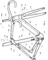
- FIG. 2 shows a perspective view of a frame assembly 12 of the bicycle 10 of FIG. 1 in accordance with an illustrative embodiment.
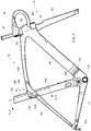
- FIG. 3 shows a side view of the frame assembly 12 of the bicycle 10 of FIG. 1 in accordance with an illustrative embodiment.
- FIG. 4 shows a side section view of the frame assembly 12 of the bicycle 10 of FIG. 1 in accordance with an illustrative embodiment. (The section hatching of elements 795, 24, 26, and 14 is for the purposes of showing contrast)
- FIG. 5 shows a front section view Section 5-5 of the frame assembly 12 of the bicycle 10 of FIG. 1 in accordance with an illustrative embodiment.
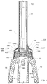
- FIG. 6 shows a perspective section view Section 6-6 of the frame assembly 12 of the bicycle 10 of FIG. 1 in accordance with an illustrative embodiment.
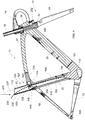
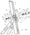
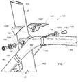
- FIG. 7 shows a perspective assembly view of the frame assembly 12 of the bicycle 10 of FIG. 1 in accordance with an illustrative embodiment.
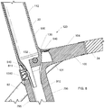
- FIG. 8 shows a side section view of the frame assembly 12 of the bicycle 10 of FIG. 1 in accordance with an illustrative embodiment.
- FIG. 9 shows a side section view of the frame assembly 12 of the bicycle 10 of FIG. 1 in accordance with an illustrative embodiment.
- the section hatching of elements 795, 62 and 68 is for the purposes of showing contrast).
- Bicycle 10 can include the frame assembly 12.
- Bicycle 10 includes a seat 16 and handlebars 18 that are attached to frame assembly 12.
- a seat post 20 can be connected to seat 16 and slidably engages a compliant seat tube 22 of frame assembly 12.
- a top tube 24 and a down tube (bottom tube) 26 extend forwardly from compliant seat tube 22 to a head tube 28 of frame 712.
- the top tube 24 and the down tube 26 can be connected by a structural seat tube 795.
- At least a portion of the seat tube 22 can be located within the structural seat tube 795.
- the structural seat tube 795 can have various cross-sections; for example, the structural seat tube 795 can have a round, oblong, elliptical or airfoil cross-section.
- Handlebars 18 can be connected to a stem or steer tube 30 that passes through head tube 28 and is connected or integrally formed with a fork crown 32. Handlebar 18 may include a stem that is constructed to slidably engage an interior cavity of steer tube 30. It is appreciated that one or more of the structures of bicycle 10 and frame assembly 12 can be constructed from similar materials, a variety of different materials, and various combinations thereof, such as steel, titanium, aluminum, and fiber reinforced plastic.
- Frame assembly 12 and compliant seat tube 22 can be formed of metal-type materials, such as aluminum-type materials, carbon fiber materials, and/or any other materials that are sufficiently formable and robust enough to support the rider of bicycle 10.
- Fork assembly 14 can include a pair of fork blades or fork legs 34 that extend from generally opposite ends of fork crown 32 and are constructed to support a front wheel assembly 36 at an end thereof or dropout 38. Dropouts 38 engage generally opposite sides of an axle 40 constructed to engage a hub 42 of front wheel assembly 36. A number of spokes 44 extend from hub 42 to a rim 46 of front wheel assembly 36. A tire 48 is engaged with rim 46 such that rotation of hub 42 and rim 46, relative to fork legs 34, rotates tire 48. Fork assembly 14 can be secured to the head tube 28 at least in part by steer cap 1540.
- Bicycle 10 includes a front brake assembly 50 having an actuator 52 attached to handlebars 18 and a pair of brake pads 53 positioned on generally opposite sides of front wheel assembly 36.
- the shape of brake assembly 50 can be blended into or nested into the shape of fork assembly 14.
- Brake pads 53 can be constructed to engage a brake wall 54 of rim 46 thereby providing a stopping or slowing force to front wheel assembly 36.
- Head tube 28 can include brake doors 291 and 292. The brake doors 291 and 29 can be opened when brake assembly 50 is rotated from side to side.
- a rear wheel assembly 56 includes a brake assembly 58 similar to front wheel brake assembly 50 but it is appreciated that one or both of front and rear wheel brake assemblies 50, 58 could be provided in other brake configurations such as a disk brake assembly wherein a rotor and a caliper are positioned proximate one or more of front wheel axle 40 or a rear axle 64, respectively.
- a rear wheel 66 is positioned generally concentrically about rear axle 64.
- a pair of seat stays 62, 68 ( FIG. 2 ) and a pair of chain stays 70, 71 ( FIG. 2 ) extend rearward relative to compliant seat tube 22 and offset rear axle 64 from a crankset 72.
- Crankset 72 includes a set of pedals 74 that is operationally connected to a flexible drive member such as a chain 76 via one or more variable diameter chain gears or a chain ring or sprocket 78.
- Rotation of chain 76 communicates a drive force to a gear cluster 80 positioned proximate rear axle 64.
- Gear cluster 80 is generally concentrically orientated with respect to rear axle 64 and includes a number of variable diameter gears.
- Gear cluster 80 is operationally connected to a hub 82 of rear wheel 66.
- a number of spokes 84 extend radially between hub 82 and a rim 86 of rear wheel 66 of rear wheel assembly 56.
- rider operation of pedals 74 drives chain 76 thereby driving rear wheel 66 which in turn propels bicycle 10.
- Fork assembly 14 is constructed to support a forward end 88 of bicycle 10 above a ground surface 90.
- Handlebar 18 is connected to frame 712 and fork assembly 14 such that operator manipulation of handlebar 18 is communicated to fork assembly 14 to facilitate rotation of front wheel assembly36 relative to frame assembly 12 along a longitudinal axis, indicated by arrow 175, of bicycle 10.
- a longitudinal plane in the direction of arrow 175 can divide the bicycle 10 into a right-side and a left side from the perspective of a rider sitting on saddle 16 and facing forward end 88. As is commonly understood, such manipulation of handlebar 18 steers bicycle 10 during riding.
- bicycle 10 shown in FIG. 1 is merely exemplary of a number of bicycle configurations. That is, whereas bicycle 10 is shown as what is commonly understood as a street or road bike, it is appreciated that the present invention is applicable to a number of bicycle configurations including those bicycles with more aggressive suspension systems commonly found in off-road or mountain bike frame configurations, and/or hybrids, crossover or multi-purpose bicycle frame configurations.
- the top tube 24 and seat stays 68 can extend in a fairly continuous manner to form an upper frame member 100 that can extend from head tube 28 to a pair of dropouts 102, 103 that support rear axle 64.
- Upper frame member 100 can be formed as one piece and/or assembled from a distinct top tube 24, seat stays 68, and/or an optional lug 104 that is disposed between the top tube 24 and the seat stays 68. It is appreciated that seat stays 62, 68 and top tube 24 of upper frame member 100 could be formed as a unitary structure, a number of discrete permanently connected elements, or connected to one another via an optional lug 104 associated with an overlap area 105 of compliant seat tube 22 and upper frame member 100.
- down tube 26, bottom bracket 110, and chain stays 70, 71 whose assemblies collectively define a lower frame member that extends from head tube 28 to one or more dropouts 102, 103 could be formed as a unitary assembly wherein bottom bracket 110 is formed with down tube 26 or chain stays 70, 71, or an assembly wherein the chain stays 70, 71 and down tube 26 can be permanently affixed to a discrete bottom bracket lug or simply bottom bracket 110.
- bicycle 10 includes a forward frame triangle that is a generally defined by the triangular shape of the direction of extension of the structural seat tube, the top tube, and the down tube of frame assembly 12 regardless of the methodology or number of discrete elements used to form the frame assembly.
- compliant seat tube 22 includes a first end 108 that is secured (e.g., bonded) to bottom bracket 110 of bicycle frame 12 and a second end 112 that extends in a generally upward direction beyond the location of the lug or overlap area 105 with upper frame member 100.
- Seat post 20 FIG. 1
- a passive pivot assembly 120 can connect an upper portion of compliant seat tube 22 to bicycle frame assembly 12 proximate overlap area 105 such that more of compliant seat tube 22 extends between pivot assembly 120 and bottom bracket 110 than extends in an upward direction relative to the intersection of compliant seat tube 22 and upper frame member 100.
- a flexible mechanical coupling can connect an upper portion of compliant seat tube 22 to bicycle frame assembly 12 proximate overlap area 105; for example, a thick gasket can support the compliant seat tube 22 in the upper frame member 100.
- flexible living hinge(s) or flexible member can connect the compliant seat tube 22 to the upper frame member 100.
- the compliant seat tube 22 can include an upper portion 930 and a lower portion 910.
- the upper portion 930 can be located above the opening 132 and the lower portion 910 can be located below the opening 132.
- the top tube 24 and the down tube 26 can be connected by a structural seat tube 795.
- the structural seat tube 795 can extend from the bottom bracket 110 to the upper frame member 100.
- the structural seat tube 795 can enclose the lower portion 910 of the compliant seat tube 22.
- the upper portion 930 can have a cross section that matches or blends with a cross section of the structural seat tube 795.
- the cross section of the upper portion 930 can be larger than the cross section of the lower portion 910.
- the lower portion 910 of the compliant seat tube 22 can flex or bend within the structural seat tube 795.
- the structural seat tube 795 can enclose the entire compliant seat tube 22.
- the structural seat tube 795 can enclose a portion of the compliant seat tube 22.
- the structural seat tube 795 can be located along the sides of the compliant seat tube 22.
- the structural seat tube 795 can be located fore, aft, or both fore and aft of the compliant seat tube 22.
- the frame 12 can also include a mounts 750 associated with the lower seat mast 795.
- a seat post or saddle can be mounted on the upper portion 930.
- the structural seat tube 795 can include a cable stop 1310 for the rear brake cable.
- Accessories such as the front derailleur and water bottle can be mounted to the structural seat tube 795.
- Passive pivot assembly 120 can complete the linkage between upper frame member 100, which includes top tube 24 and the structures associated with seat stays 62, 68.
- a lower end of compliant seat tube 22 is secured to lower frame member 101, which includes the down tube 26 and bottom bracket 110 and preferably one of more chain stays 70, 71.
- structural seat tube 795, top tube 24 and down tube 25 collectively generally define the forward triangle of frame assembly 12.
- Frame assembly 12 has a fairly robust and stable feel during use but is also constructed to provide impact dampening performance in a manner that does not allow changing of the relative connection points of any of the respective members of the forward frame triangle.
- the non-bonded rigid yet pivotable connection of compliant seat tube 22 with upper frame member 100 allows deflection of compliant seat tube 22 in a vertical plane and in a direction along the longitudinal length of the compliant seat tube 22 so as to allow the frame assembly 12 to provide a limited degree of suspension performance or vertical compliance without altering the orientation of the connection points of any of the frame members relative to one another.
- the overlap area 105 can include a passage 130 that is shaped to allow compliant seat tube 22 to pass therethrough.
- An opening 132 can be formed laterally through compliant seat tube 22 and shaped to rotationally cooperate with pivot assembly 120.
- compliant seat tube 22 merely pass over an axis or longitudinal area associated with one or more of the top tube, the seat stays, and/or a fabrication lug being formed therebetween.
- the seat tube could be perforated or otherwise contoured to pass generally around the more horizontal structure of the top tube and/or the seat stays associated with upper frame member 100.
- the seat tube could pass rearward relative to the closed structure of top tube 24 so as to be positioned in the space generally flanked by the seat stays.
- Each configuration allows limited passive pivoting between seat stays 70, 71 and the adjacent structure of upper frame member 100 of bicycle frame assembly 12.
- a first gasket 940 can be located between the upper portion 930 and the upper frame member 100.
- the passage 130 can be bounded on a forward side 131 by an end wall associated with top tube 24 or a portion of the respective frame lug 104.
- the first gasket 134 can be disposed between forward side 131 of overlap area 105 and top tube 24 and generally surrounds a forward side 136, and opposite lateral sides 138, 140 of compliant seat tube 22.
- the first gasket 940 can prevent moisture and/or dirt and/or debris from entering the pivot area associated with passage 130 and the passage of compliant seat tube 22 therethrough but does not otherwise interfere with the flexion of compliant seat tube 22 during use of bicycle 10 as described further below.
- Passage 130 can be bounded on opposite lateral sides by side walls 142, 144 of upper frame member 100. Passage 130 can also be bounded by rear wall 811 of structural seat tube 795. An optional rear web wall 146 can also complete the definition of passage 130 such that upper frame member 100 completely surrounds compliant seat tube 22 with web wall 146 extending laterally between seat stays 62, 68.
- the pivot assembly 120 can include a first bolt or other fastener 150, a second bolt or other fastener 152, a guide sleeve 154, and first and second bearings or bushings 156, 158.
- Each of fasteners 150, 152 includes a threaded portion 160, a stem portion 162, and a head portion 164. The radial diameter of each fastener 150, 152 gradually increase from the respective threaded portion 160 to the stem portion 162 to the head portion 164.
- One or each of head portions 164 includes a drive surface 166 that is shaped to cooperate with a driving tool, such as a hex driver or the like for securing each of first and second fasteners 150, 152 relative to pivot assembly 120.
- driving surface 166 could have any number of shapes and/or be provided on a radial exterior surface of the corresponding fastener 150, 152. It is further appreciated that one of fasteners 150, 152 could formed integrally with sleeve 154 such that operation of one respective fastener secures pivot assembly 120 relative to bicycle frame assembly 12.
- Each bushing 156, 158 includes an outer radial surface 170, an inner radial surface 172, an outboard lateral surface 174, and an inboard lateral surface 176.
- the inboard and outboard lateral directions associated with surfaces 174, 176 of each bushing 156, 158 refers to the orientation of surfaces 170, 174 relative to a longitudinal vertical plane that contains longitudinal axis 175 of bicycle 10 and the relative position of the respective surfaces and/or structures relative to the same.
- surfaces 176 of bushings 156, 158 are nearer a longitudinal axis, indicated by line 178, of upper frame member100.
- surfaces 174 are further outboard and surfaces 176 are further inboard relative to one another and longitudinal axis 178 of upper frame member 100 along a longitudinal axis, indicated by line 180, of pivot assembly 120.
- the longitudinal axis 180 of pivot assembly 120 is oriented in a crossing direction relative to, and is preferably normal to, longitudinal axis 178 of upper frame member 100.
- a first opening 184 and the second opening 186 can be formed in each of the respective sidewalls 142, 144 of upper frame member 100 and centered along axis 180 of pivot assembly 120.
- a seat 188 extends circumferentially about at least one of openings 184, 186 in the lateral outboard facing surface of the respective sidewall142, 144.
- Seat 188 is defined by a lip 190 that extends circumferentially about the corresponding opening 184, 186 and is shaped to cooperate with sleeve 154 and a corresponding bushing 156, 158.
- Sleeve 154 includes a stem portion 194, the head portion 196, and an opening 198 formed therethrough.
- Sleeve 154 is constructed to slidably cooperate with openings 184, 186 in a direction aligned with axis 180.
- head portion 196 of sleeve 154 sits in opening 132 of compliant seat tube 22.
- Opening 132 of compliant seat tube 22 circumferentially cooperates with stem portion 194 of sleeve 154 when the longitudinal axis of opening 132 is aligned axis 180 of pivot assembly 120.
- compliant seat tube 22 bends in a plane that is normal to the axis of opening 132 of compliant seat tube 22, indicated by line 180.
- Threaded portions 160 of each fastener 150, 152 operatively cooperate with a threaded surface 210 formed on an inner radial surface of sleeve 154.
- Bearings 156, 158 can rotatably cooperate with stem portion 162 of each of fasteners 150, 152 and cooperate with seats 188 defined by upper frame member 100.
- the pivot assembly 120 can include a first cover 1025 and a second cover 1027 that cooperate with the laterally outboard directed sides of pivot assembly 120.
- the laterally inboard facing side of the first cover 1025 and the second cover 1027 can include an attachment mechanism that is shaped to snuggly cooperate with a radially outboard directed surface of head portion 164 of a respective fastener 150, 152.
- upper frame member 100 includes a recess that is shaped to mimic the shape of the first cover 1025 and the second cover 1027 such that when assembled, the first cover 1025 and the second cover 1027 provides a generally smooth contour along the exterior surface of upper frame member 100 associated with pivot assembly 120.
- pivot assembly 120 When assembled, pivot assembly 120 provides a secure connection between upper frame member 100 and compliant seat tube 22 and, with structural seat tube 795, does so in a manner that prevents lateral, longitudinal, and vertical movement of compliant seat tube 22 at axis 180 relative to upper frame member 100 but allows rotation of compliant seat tube 22 about axis 180 associated with opening 132 which is collinear with pivot assembly 120 relative to upper frame member 100.
- Such a connection allows only flexion or flexing movement of seat tube22 relative to the other structural members of bicycle frame assembly 12 during use of bicycle 10.
- compliant seat tube 22 could include a passage like passage 130 or otherwise be contoured so that the seat tube passed around the top tube/seat stays/lug and/or such that the top tube/seat stays/lug pass through the seat tube.
- Still another alternative includes connecting the seat stays to the upper frame member or top tube at a location forward of the seat tube such that the seat tube would be positioned in an area generally flanked by the seat stays.
- axis 180 of pivot assembly 120 is offset in an forward direction relative to the longitudinal axis 206 of compliant seat tube 22, is appreciated that axis 180 could be oriented to intersect axis 206 or offset in a rearward direction relative thereto so as to alter the deflection performance of compliant seat tube 22 and/or to better suit the preferences of a given rider or class of users.
- interchangeable stiffening rods, tubes, or inserts can be placed inside the compliant seat tube 22 along at least a portion of the length of the compliant seat tube 22.
- preload on the passive pivot assembly 120 can be increased or decreased to change the compliance (or flexibility) of the compliant seat tube 22.
- compliant seat tube 22 During normal use of frame assembly 12, compliant seat tube 22 maintains a generally "at rest" configuration as represented by compliant seat tube 22 shown in FIG. 4 .
- compliant seat tube 22 has a fairly linear at rest orientation. Understandably, during normal use, some initial deflection of compliant seat tube 22 may occur depending on the weight and preferred orientation of the rider during normal use over relatively smooth terrain.
- a downward and rearward bending moment is imparted to compliant seat tube 22 by the interaction of the rider with the rear portion of a saddle, which is commonly offset to the rear of the longitudinal centerline 206 of compliant seat tube 22.
- Such loading of the seat tube allows the compliant seat tube 22 to pivot in a passive manner about pivot assembly 120 and results in a rearward deflection of an upper portion 232 of compliant seat tube 22 positioned above pivot assembly 120 and a forward deflection of a lower portion 234 of compliant seat tube 22 that is positioned between pivot assembly 120 and bottom bracket 110 relative to the at-rest orientation.
- line 236 The deflection of compliant seat tube 22 relative to upper frame member 100 and lower frame member 101 is shown graphically in FIG. 4 by line 236 relative to line 237.
- Line 237 shows an exemplary at rest centerline of compliant seat tube 22; and
- line 236 shows an exemplary deflection centerline line of compliant seat tube 22 under load.
- Such a configuration allows near the entirety of compliant seat tube 22 to deflect from an at rest position to a "bent" orientation, represented by line 236 to improve the vertical compliance of frame assembly 12 while structural seat tube 795 maintains rigidity between upper frame member 100 and bottom bracket 110.
- compliant seat tube 22 deflects no more than 15 degrees from an at rest orientation. In another embodiment, compliant seat tube 22 deflects no more than 7 degrees from a rest position in response to rider interaction with seat 16.
- the greatest deflection value is associated with a deflection that a rider will tolerate and still feel comfortable on the bicycle during most riding conditions to a near unperceivable deflection during most riding conditions.
- frame assembly 12 provides greater longitudinal deflection of the seat tube with comparable lateral stiffness for bicycle frames having similar shapes and with nearly negligible contribution to the overall weight of the bicycle frame assembly. It is further envisioned that the forward and/or rearward orientation of the pivot axis relative to the longitudinal axis of the seat tube can be manipulated to satisfy a wide variety of rider performance preferences and/or to alter the deflection performance of the seat tube. It is further appreciated that the construction of the seat tube can be manipulated to further alter the vertical compliance of the frame assembly while providing a robust bicycle frame assembly.
- bicycle frame assembly 12 provides a bicycle frame have acceptable frame responsiveness with improved vertical compliance for improving rider comfort.
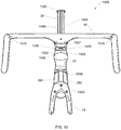
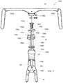
- FIG. 10 a front view of a handlebar assembly 1500 of the frame assembly 12 of the FIG. 1 in accordance with an illustrative embodiment is shown.
- FIG. 11 a front assembly view of the handlebar assembly 1500 of the frame assembly 12 of the FIG. 10 in accordance with an illustrative embodiment is shown.
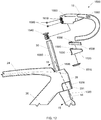
- FIG. 12 a side assembly view of the handlebar assembly 1500 of the frame assembly 12 of the FIG. 10 in accordance with an illustrative embodiment is shown.
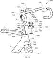
- FIG. 13 a perspective assembly view of the handlebar assembly 1500 of the frame assembly 12 of the FIG. 10 in accordance with an illustrative embodiment is shown. Referring now to FIG.
- FIG. 14 a side section view of the handlebar assembly 1500 of the frame assembly 12 of the FIG. 10 in accordance with an illustrative embodiment is shown. (The section hatching of elements 24, 26, and 28 is for the purposes of showing contrast)
- FIG. 15 a front section view Section 15-15 of the handlebar assembly 1500 of the frame assembly 12 of the FIG. 10 in accordance with an illustrative embodiment is shown.
- the handlebar assembly 1500 can include handlebars 18, a right base spacer 1520, a left base spacer 1525, a right spacer 1530, a left spacer 1535, a brake cover 1508, a bushing 1510, and a steer cap 1540.
- the handlebars 18 can include a stem 1550 and openings 1570 and 1580.
- the handlebars 18, including stem 1550, can be generally hollow.
- the stem 1550 can be secured to the steer tube 30 by pinch bolts 1560.
- the steer tube 30 can include a right flat face 1560 and a left flat face 1565 located along the right and left sides of the steer tube 30, respectively.
- the stem and handlebars can be separate pieces.
- the right base spacer 1520 can include a first connecting mechanism 1522 and a second connecting mechanism 1523.
- the left base spacer 1525 can include a first connecting mechanism 1527 and a second connecting mechanism 1528.
- the respective first connecting mechanisms 1522, 1527 and the respective second connecting mechanisms 1523, 1528 can be used to connect the right base spacer 1520 and the left base spacer 1525 together.
- the first connecting mechanisms 1522, 1527 and the respective second connecting mechanisms 1523, 1528 can be hooks that mate.
- fasteners can be used to connect the right base spacer 1520 and the left base spacer 1525 together.
- the right base spacer 1520 and the left base spacer 1525 can include alignment posts 1590.
- the right base spacer 1520 and the left base spacer 1525 can include a cable exit 1630.
- the right base spacer 1520 and the left base spacer 1525 when connected together around the steer tube 30, can true up the top of the right base spacer 1520 and the left base spacer 1525 to the top of the top tube 24 so that additional spacers can be added.
- the right spacer 1530 can include a first connecting mechanism 1532 and a second connecting mechanism 1533.
- the left spacer 1535 can include a first connecting mechanism 1537 and a second connecting mechanism 1538.
- the respective first connecting mechanisms 1532, 1537 and the respective second connecting mechanisms 1533, 1538 can be used to connect the right spacer 1530 and the left spacer 1535 together.
- the first connecting mechanisms 1532, 1537 and the respective second connecting mechanisms 1533, 1538 can be hooks that mate.
- fasteners can be used to connect the right spacer 1530 and the left spacer 1535 together.
- the right spacer 1530 and the left spacer 1535 can include alignment posts 1590.
- the alignment posts 1590 can fix the stem 1550, the right spacer 1530, the left spacer 1535, the right base spacer 1520 and the left base spacer 1525 together so that they rotate around the steer tube 30 together.
- the steer tube 30 passes through the head tube 28.
- the bushing 1510 can be placed on steer tube 30 and can sit on the top of the head tube 28. In one embodiment, the bushing 1510 can be place in a top headset bearing located proximate the top of the head tube 28.
- the right base spacer 1520 and the left base spacer 1525 can be placed around the steer tube 30 and connected.
- the right spacer 1530, the left spacer 1535 can be placed around the steer tube 30 and connected.
- the handlebars 18 can be placed around the steer tube 30 and the stem 1550 can be tightened around the steer tube 30 by pinch bolts 1560.
- the steer cap 1540 can be inserted into the steer tube 30.
- Additional spacer elements can be added to adjust the height of handlebars 18.
- the steer tube 30 can be trimmed after sizing for the specific rider.
- the connecting mechanisms of the spacers enable a bike mechanic to easily change the number of spacer elements without breaking the cabling.
- Cables 1410, 1420, 1430 and 1440 can be routed within the handlebar assembly 1500 and inside frame assembly 12. Cables 1410, 1420, 1430 and 1440 can be, for example, a traditional Bowden-type cable, i.e., a shielded cable. Cables 1410, 1420, 1430 and 1440 can be used to connect control levers and components such as brakes and deraille.
- the right base spacer 1520 and the left base spacer 1525 can include inboard openings or areas through which Cables 1410, 1420, 1430 and 1440 can pass.
- the right base spacer 1520 and the left base spacer 1525 can include inboard openings or areas through which cables 1410, 1420, 1430 and 1440 can pass.
- the bushing 1510 include inboard openings or areas through which cables 1410, 1420, 1430 and 1440 can pass.
- cables 1420, 1430 and 1440 can be routed through opening 1570 or opening 1580, inside handlebars 18, through stem 1550, through the right spacer 1530 or the left spacer 1535 and the right base spacer 1520 or the left base spacer 1525 while passing the right flat face 1560 or the left flat face 1565; out of the cable exit 1630, in the cable entry 1595 and into frame 12.
- the cable entry 1595 can include a cable guide 1910.
- the width of the cable exit 1630 and the cable entry 1595 are sized to allow for turning of the fork assembly 14.
- Cables 1420, 1430 and 1440 can be routed, for example, to the rear brake, front derailleur, or rear derailleur.
- the cable entry 1595 can be located at a front, top of the top tube 24 and generally behind the right base spacer 1520 and the left base spacer 1525.
- the cables can be located within the frame 12 to reduce drag.
- a cable 1410 can be routed through opening 1570 or opening 1580, inside handlebars 18, through stem 1550, through the right spacer 1530 or the left spacer 1535 and the right base spacer 1520 and/or the left base spacer 1525 while passing against a front cable tray 1490 molded into the front of the steer tube 30; through the bushing 1510, and into the inside of the head tube 28.
- the bushing 1510 can have an opening through which cable 1410 passes.
- cable 1410 can be coupled to the front brake assembly 50 which is attached to the fork assembly 14 at a brake mounting surface 1320. As a rider turns the fork assembly 14, the cable 1410 and a cable attachment portion of the front brake assembly 50 may need to sweep outside head tube 28.
- Head tube 28 can include a brake cover 1508 including brake doors 291 (right) and 292 (left).
- the brake doors 291 and 292 swing on hinges 293.
- the brake doors 291 and 292 can be opened by the brake assembly 50 when brake assembly 50 is rotated from side to side.
- the brake doors 291 and 292 can be opened to provide access to brake assembly 50 to attach or adjust cabling.
- the cables can be located within the frame 12 to reduce drag.
- cables 1420, 1430 and 1440 can be routed to other areas of the bike such as the tips of fork blades or next to shocks. In alternative embodiments, cables 1420, 1430 and 1440 can be hydraulic lines.
- FIG. 16 a perspective view of the down tube 26 of the frame assembly 12 of FIG. 1 in accordance with an illustrative embodiment is shown.
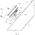
- FIG. 17 a side view of the down tube 26 the frame assembly 12 of FIG. 1 in accordance with an illustrative embodiment is shown.
- FIG. 18 a side section view of the down tube 26 the frame assembly 12 of FIG. 1 in accordance with an illustrative embodiment is shown.
- a barrel adjuster assembly 2110 can be located in a down tube opening 2126 of the down tube 26.
- the barrel adjuster assembly 2110 can included a barrel adjuster body 2115, a cover plate 2140, an adjustable cable stop 2160, a biasing spring 2130, a finger wheel 2120, a cable stop 2150, and fasteners 2145.
- the adjustable cable stop 2160 can be threaded into the barrel adjuster assembly 2110.
- the finger wheel 2120 can be attached to the adjustable cable stop 2160 such that when the finger wheel 2120 is turned, the adjustable cable stop 2160 can move towards and away from the barrel adjuster body 2115.
- Detents 2210 on the adjustable cable stop 2160 and the barrel adjuster body 2115 create a tactile adjustment response and lock the position of the adjustable cable stop 2160.
- the biasing spring 2130 is captured between the adjustable cable stop 2160 and the barrel adjuster body 2115.
- the adjustable cable stop 2160 can be locked to the barrel adjuster assembly 2110 by clip 2161.
- the cover plate 2140 can include an opening 2147 to provide access to the finger wheel 2120.
- the finger wheel 2120 can be accessible from the outside of the down tube 26 via the opening 2147 in cover plate 2140.
- the barrel adjuster assembly 2110 can be secured in the down tube opening 2126 by fasteners 2145.
- Cable 1430 can be tensioned by adjustable cable stop 2160.
- An outer sheathing 1432 of cable 1430 can rest in a cup of adjustable cable stop 2160.
- the control cable 1432 of cable 1430 can pass through a passage in the adjustable cable stop 2160.
- Cable 1440 can be secured by cable stop 2150.
- An outer sheathing 1442 of cable 1440 can rest in a cup of cable stop 2150.
- the control cable 1442 of cable 1440 can pass through a passage in the cable stop 2150.
- tensioning and stability of the internal cabling can be accomplished with internal components.
- a bicycle frame assembly has a forward frame triangle that includes a top tube and a bottom tube.
- the top tube includes a first end that is connected to a head tube and a second end.
- the bottom tube includes a first end that is connected to the head tube and a second end.
- a bottom bracket is connected to the second end of the bottom tube.
- a seat tube extends in an upward direction from the bottom bracket.
- a pair of seat stays are connected to the top tube and extend in a rearward direction beyond the forward frame triangle.
- a pivot connects the seat tube to the forward frame triangle proximate the top tube at a location nearer a bicycle seat than the bottom bracket.
- Another arrangement includes one or more features combinable with the above arrangement includes a bicycle frame assembly having an upper frame member that includes a top tube and a pair of seat stays.
- the upper frame member extends between a dropout associated with a rear wheel and a head tube.
- An opening is formed in the upper frame member.
- a lower frame member that includes a bottom tube, a bottom bracket, and a chain stay extends between the dropout and the head tube.
- a seat tube extends from the lower frame member toward the upper frame member and passes through the opening in the upper frame member.
- a pivot connects the seat tube to the upper frame member proximate the opening so that more of the seat tube is located between the pivot and the bottom bracket than extends beyond the upper frame member.
- a seat tube is connected to a bottom bracket.
- the seat tube is connected to an upper frame member with a pivot that is located at an overlapping intersection of the seat tube and the upper frame member so that the seat tube can deflect from alignment along a line between the bottom bracket and the pivot.
- any two components so associated can also be viewed as being “operably connected”, or “operably coupled”, to each other to achieve the desired functionality, and any two components capable of being so associated can also be viewed as being “operably couplable”, to each other to achieve the desired functionality.
- operably couplable include but are not limited to physically mateable and/or physically interacting components and/or wirelessly interactable and/or wirelessly interacting components and/or logically interacting and/or logically interactable components.
Landscapes
- Engineering & Computer Science (AREA)
- Mechanical Engineering (AREA)
- Transportation (AREA)
- Physics & Mathematics (AREA)
- General Physics & Mathematics (AREA)
- Automation & Control Theory (AREA)
- Steering Devices For Bicycles And Motorcycles (AREA)
- Motorcycle And Bicycle Frame (AREA)
Description
- The present invention relates to bicycles and, more particularly, to bicycle frames with improved compliance and improved cable routing.
- Riders may desire a rigid frame to maximize power transfer while still having compliance in their bicycles. Further, riders may desire internal cable routing to improve aerodynamics. Therefore, new and improved ways to provide compliance and route cables in bicycle frames are needed.
-
FR836294 -
US2011/248470 , on which the preamble of claim 1 is based, discloses a bicycle seat tube assembly and seat post that can be arranged to reduce vibrations that originate at the bicycle wheel and are transmitted to the rider of the bicycle. A saddle can be configured to be supported by a seat post which connects to a bicycle frame at the seat tube assembly. An open cavity can be formed between the seat tube assembly and the seat post. The open cavity can be configured to allow the system to act as a spring. Further, spring stiffness can be adjusted to reduce vibrations and increase damping. - The present invention provides a bicycle according to claim 1.
- According to one aspect of the disclosure, there is also provided a frame assembly having a structurally enclosed, deflectable seat tube that overcomes one or more of the aforementioned drawbacks. One aspect includes a bicycle frame assembly having an upper frame member and a lower frame member. The upper frame member can be connected to the lower frame member by a structural seat tube. The upper frame member can include a top tube and a pair of seat stays and extends between a dropout and a head tube in a generally continuous manner. The lower frame member can include a bottom tube, a bottom bracket, and a chain stay and can extend between the dropout and the head tube. A compliant seat tube can extend from the lower frame member toward the upper frame member through the structural seat tube and pass beyond the top tube. The compliant seat tube can be connected to the upper frame member by a pivot so that more of the compliant seat tube is located between the pivot and the bottom bracket than extends beyond the upper frame member. An opening can be formed through the top tube or a lug that connects the seat stays with the top tube proximate to the top of the structural seat tube. The compliant seat tube can pass through the opening in the upper frame member. Alternatively, the compliant seat tube could be perforated or otherwise contoured to pass generally around the more horizontal structure of the top tube and/or the seat stays. As another alternative, the seat tube could pass rearward relative to the top tube so as to be positioned in the space generally flanked by the seat stays.
- Another aspect that is useable with one or more of the above aspects can be a bicycle frame assembly that includes a forward frame triangle that can include a top tube and a bottom tube connected by a structural seat tube. The top tube can include a first end that is connected to a head tube and a second end. The bottom tube can include a first end that is connected to the head tube and a second end. A bottom bracket can be connected to the second end of the bottom tube. A compliant seat tube can extend in an upward direction from the bottom bracket and a pair of seat stays can be connected to the top tube and extend in a rearward direction beyond the forward frame triangle. A pivot can connect the compliant seat tube to the forward frame triangle proximate the top tube at a location nearer a bicycle seat than the bottom bracket. The pivot allows that portion of the compliant seat tube disposed between the pivot and the bottom bracket to adjustably deflect from an at rest position during vertical loading of the compliant seat tube.
- Another aspect that is useable with one or more of the above aspects includes a bicycle frame assembly having an upper frame member that can include a top tube and a pair of seat stays. The upper frame member can extend between a dropout associated with a rear wheel and a head tube. An opening can be formed in the upper frame member. A lower frame member can include a bottom tube, a bottom bracket, and a chain stay can extend between the dropout and the head tube. A seat tube can extend from the lower frame member toward the upper frame member and can pass through the opening in the upper frame member. The seat tube can be enclosed by a structural seat tube. A pivot can connect the compliant seat tube to the upper frame member proximate the opening so that more of the compliant seat tube is located between the pivot and the bottom bracket than extends beyond the upper frame member.
- Another aspect that is useable with one or more of the above aspects includes a method of allowing deflection of a compliant seat tube while maintaining the rigidity of the frame triangle. A compliant seat tube is connected to a bottom bracket. The compliant seat tube is connected to an upper frame member with a pivot that is located at an overlapping intersection of the compliant seat tube and the upper frame member so that the compliant seat tube can deflect from alignment along a line between the bottom bracket and the pivot.
- In an embodiment according to the present invention a bicycle includes a forward frame triangle that comprises a top tube, a bottom tube, a bottom bracket, a structural seat tube, a compliant seat tube, and a pair of seat stays connected to the top tube and extending in a rearward direction beyond the forward frame triangle. The top tube has a first end connected to a head tube and a second end. The bottom tube has a first end connected to the head tube and a second end. The bottom bracket is connected to the second end of the bottom tube. The structural seat tube is connected to the bottom bracket and the top tube. The compliant seat tube extends in an upward direction from the bottom bracket to the top tube and within the structural seat tube. The compliant seat tube is coupled to the forward frame triangle such that the compliant seat tube can bend within the structural seat tube.
- In another illustrative example, not being an embodiment according to the present invention, a bicycle can include a frame, a fork, handlebars, at least one spacer, and an internal cable. The frame can include a top tube and a head tube. The fork can include a steer tube. The steer tube can comprise at least one routing feature selected from a flat face and a cable tray. The internal cable can be routed at least partially inside the handlebars to the steer tube. The internal cable can be routed between the routing feature of the steer tube and the spacer.
- The foregoing and other features of the present disclosure will become more fully apparent from the following description and appended claims, taken in conjunction with the accompanying drawings. Understanding that these drawings depict only several embodiments in accordance with the disclosure and are, therefore, not to be considered limiting of its scope, the disclosure will be described with additional specificity and detail through use of the accompanying drawings.
-
FIG. 1 is a side view of abicycle 10 in accordance with an illustrative embodiment. -
FIG. 2 is a perspective view of aframe assembly 12 of thebicycle 10 ofFIG. 1 in accordance with an illustrative embodiment. -
FIG. 3 is a side view of theframe assembly 12 of thebicycle 10 ofFIG. 1 in accordance with an illustrative embodiment. -
FIG. 4 is a side section view of theframe assembly 12 of thebicycle 10 ofFIG. 1 in accordance with an illustrative embodiment. -
FIG. 5 is a front section view Section 5-5 of theframe assembly 12 of thebicycle 10 ofFIG. 1 in accordance with an illustrative embodiment. -
FIG. 6 is a perspective section view Section 5-5 of theframe assembly 12 of thebicycle 10 ofFIG. 1 in accordance with an illustrative embodiment. -
FIG. 7 is a perspective assembly view of theframe assembly 12 of thebicycle 10 ofFIG. 1 in accordance with an illustrative embodiment. -
FIG. 8 shows a side section view of theframe assembly 12 of thebicycle 10 ofFIG. 1 in accordance with an illustrative embodiment. -
FIG. 9 shows a side section view of theframe assembly 12 of thebicycle 10 ofFIG. 1 in accordance with an illustrative embodiment. -
FIG. 10 is a front view of ahandlebar assembly 1500 of theframe assembly 12 of theFIG. 1 in accordance with an illustrative embodiment. -
FIG. 11 is a front assembly view of thehandlebar assembly 1500 of theframe assembly 12 of theFIG. 10 in accordance with an illustrative embodiment. -
FIG. 12 is a side assembly view of thehandlebar assembly 1500 of theframe assembly 12 of theFIG. 10 in accordance with an illustrative embodiment. -
FIG. 13 is a perspective assembly view of thehandlebar assembly 1500 of theframe assembly 12 of theFIG. 10 in accordance with an illustrative embodiment. -
FIG. 14 is a side section view of thehandlebar assembly 1500 of theframe assembly 12 of theFIG. 10 in accordance with an illustrative embodiment. -
FIG. 15 is a front section view of thehandlebar assembly 1500 of theframe assembly 12 of theFIG. 10 in accordance with an illustrative embodiment. -
FIG. 16 is a perspective view of thedown tube 26 of theframe assembly 12 ofFIG. 1 in accordance with an illustrative embodiment. -
FIG. 17 is a side view of thedown tube 26 theframe assembly 12 ofFIG. 1 in accordance with an illustrative embodiment. -
FIG. 18 is a side section view of thedown tube 26 theframe assembly 12 ofFIG. 1 in accordance with an illustrative embodiment. - In the following detailed description, reference is made to the accompanying drawings, which form a part hereof. In the drawings, similar symbols typically identify similar components, unless context dictates otherwise. The illustrative embodiments described in the detailed description, drawings, and claims are not meant to be limiting. Other embodiments may be utilized, and other changes may be made, without departing from the scope of the subject matter presented here. It will be readily understood that the aspects of the present disclosure, as generally described herein, and illustrated in the figures, can be arranged, substituted, combined, and designed in a wide variety of different configurations, all of which are explicitly contemplated and make part of this disclosure.
-
FIG. 1 shows a side view of abicycle 10 in accordance with an illustrative embodiment.FIG. 2 shows a perspective view of aframe assembly 12 of thebicycle 10 ofFIG. 1 in accordance with an illustrative embodiment.FIG. 3 shows a side view of theframe assembly 12 of thebicycle 10 ofFIG. 1 in accordance with an illustrative embodiment.FIG. 4 shows a side section view of theframe assembly 12 of thebicycle 10 ofFIG. 1 in accordance with an illustrative embodiment. (The section hatching ofelements FIG. 5 shows a front section view Section 5-5 of theframe assembly 12 of thebicycle 10 ofFIG. 1 in accordance with an illustrative embodiment. (The section hatching ofelements FIG. 6 shows a perspective section view Section 6-6 of theframe assembly 12 of thebicycle 10 ofFIG. 1 in accordance with an illustrative embodiment. (The section hatching ofelements FIG. 7 shows a perspective assembly view of theframe assembly 12 of thebicycle 10 ofFIG. 1 in accordance with an illustrative embodiment.FIG. 8 shows a side section view of theframe assembly 12 of thebicycle 10 ofFIG. 1 in accordance with an illustrative embodiment. (The section hatching ofelements FIG. 9 shows a side section view of theframe assembly 12 of thebicycle 10 ofFIG. 1 in accordance with an illustrative embodiment. (The section hatching ofelements -
Bicycle 10 can include theframe assembly 12.Bicycle 10 includes aseat 16 andhandlebars 18 that are attached to frameassembly 12. Aseat post 20 can be connected toseat 16 and slidably engages acompliant seat tube 22 offrame assembly 12. Atop tube 24 and a down tube (bottom tube) 26 extend forwardly fromcompliant seat tube 22 to ahead tube 28 of frame 712. Thetop tube 24 and thedown tube 26 can be connected by astructural seat tube 795. At least a portion of theseat tube 22 can be located within thestructural seat tube 795. Thestructural seat tube 795 can have various cross-sections; for example, thestructural seat tube 795 can have a round, oblong, elliptical or airfoil cross-section.Handlebars 18 can be connected to a stem or steertube 30 that passes throughhead tube 28 and is connected or integrally formed with afork crown 32.Handlebar 18 may include a stem that is constructed to slidably engage an interior cavity ofsteer tube 30. It is appreciated that one or more of the structures ofbicycle 10 andframe assembly 12 can be constructed from similar materials, a variety of different materials, and various combinations thereof, such as steel, titanium, aluminum, and fiber reinforced plastic.Frame assembly 12 andcompliant seat tube 22 can be formed of metal-type materials, such as aluminum-type materials, carbon fiber materials, and/or any other materials that are sufficiently formable and robust enough to support the rider ofbicycle 10. -
Fork assembly 14 can include a pair of fork blades or forklegs 34 that extend from generally opposite ends offork crown 32 and are constructed to support afront wheel assembly 36 at an end thereof ordropout 38.Dropouts 38 engage generally opposite sides of anaxle 40 constructed to engage ahub 42 offront wheel assembly 36. A number ofspokes 44 extend fromhub 42 to arim 46 offront wheel assembly 36. Atire 48 is engaged withrim 46 such that rotation ofhub 42 andrim 46, relative to forklegs 34, rotatestire 48.Fork assembly 14 can be secured to thehead tube 28 at least in part bysteer cap 1540. -
Bicycle 10 includes afront brake assembly 50 having an actuator 52 attached tohandlebars 18 and a pair ofbrake pads 53 positioned on generally opposite sides offront wheel assembly 36. The shape ofbrake assembly 50 can be blended into or nested into the shape offork assembly 14.Brake pads 53 can be constructed to engage abrake wall 54 ofrim 46 thereby providing a stopping or slowing force tofront wheel assembly 36.Head tube 28 can includebrake doors brake doors 291 and 29 can be opened whenbrake assembly 50 is rotated from side to side. Arear wheel assembly 56 includes abrake assembly 58 similar to frontwheel brake assembly 50 but it is appreciated that one or both of front and rearwheel brake assemblies front wheel axle 40 or arear axle 64, respectively. Arear wheel 66 is positioned generally concentrically aboutrear axle 64. - A pair of seat stays 62, 68 (
FIG. 2 ) and a pair of chain stays 70, 71 (FIG. 2 ) extend rearward relative tocompliant seat tube 22 and offsetrear axle 64 from acrankset 72.Crankset 72 includes a set ofpedals 74 that is operationally connected to a flexible drive member such as achain 76 via one or more variable diameter chain gears or a chain ring orsprocket 78. Rotation ofchain 76 communicates a drive force to agear cluster 80 positioned proximaterear axle 64.Gear cluster 80 is generally concentrically orientated with respect torear axle 64 and includes a number of variable diameter gears. -
Gear cluster 80 is operationally connected to ahub 82 ofrear wheel 66. A number ofspokes 84 extend radially betweenhub 82 and arim 86 ofrear wheel 66 ofrear wheel assembly 56. As is commonly understood, rider operation ofpedals 74drives chain 76 thereby drivingrear wheel 66 which in turn propelsbicycle 10.Fork assembly 14 is constructed to support aforward end 88 ofbicycle 10 above aground surface 90.Handlebar 18 is connected to frame 712 and forkassembly 14 such that operator manipulation ofhandlebar 18 is communicated to forkassembly 14 to facilitate rotation of front wheel assembly36 relative to frameassembly 12 along a longitudinal axis, indicated byarrow 175, ofbicycle 10. A longitudinal plane in the direction ofarrow 175 can divide thebicycle 10 into a right-side and a left side from the perspective of a rider sitting onsaddle 16 and facing forward end 88. As is commonly understood, such manipulation ofhandlebar 18steers bicycle 10 during riding. - The construction of
bicycle 10 shown inFIG. 1 is merely exemplary of a number of bicycle configurations. That is, whereasbicycle 10 is shown as what is commonly understood as a street or road bike, it is appreciated that the present invention is applicable to a number of bicycle configurations including those bicycles with more aggressive suspension systems commonly found in off-road or mountain bike frame configurations, and/or hybrids, crossover or multi-purpose bicycle frame configurations. - The
top tube 24 and seat stays 68 can extend in a fairly continuous manner to form anupper frame member 100 that can extend fromhead tube 28 to a pair ofdropouts rear axle 64.Upper frame member 100 can be formed as one piece and/or assembled from a distincttop tube 24, seat stays 68, and/or anoptional lug 104 that is disposed between thetop tube 24 and the seat stays 68. It is appreciated that seat stays 62, 68 andtop tube 24 ofupper frame member 100 could be formed as a unitary structure, a number of discrete permanently connected elements, or connected to one another via anoptional lug 104 associated with anoverlap area 105 ofcompliant seat tube 22 andupper frame member 100. In a similar manner, it is also appreciated that downtube 26,bottom bracket 110, and chain stays 70, 71, whose assemblies collectively define a lower frame member that extends fromhead tube 28 to one ormore dropouts bottom bracket 110 is formed withdown tube 26 or chain stays 70, 71, or an assembly wherein the chain stays 70, 71 and downtube 26 can be permanently affixed to a discrete bottom bracket lug or simplybottom bracket 110. Once assembled, as shown inFIG. 1 ,bicycle 10 includes a forward frame triangle that is a generally defined by the triangular shape of the direction of extension of the structural seat tube, the top tube, and the down tube offrame assembly 12 regardless of the methodology or number of discrete elements used to form the frame assembly. - In one illustrative embodiment,
compliant seat tube 22 includes afirst end 108 that is secured (e.g., bonded) tobottom bracket 110 ofbicycle frame 12 and asecond end 112 that extends in a generally upward direction beyond the location of the lug oroverlap area 105 withupper frame member 100. Seat post 20 (FIG. 1 ) can telescopically cooperate withcompliant seat tube 22 offrame assembly 12. Apassive pivot assembly 120 can connect an upper portion ofcompliant seat tube 22 tobicycle frame assembly 12proximate overlap area 105 such that more ofcompliant seat tube 22 extends betweenpivot assembly 120 andbottom bracket 110 than extends in an upward direction relative to the intersection ofcompliant seat tube 22 andupper frame member 100. In an alternative embodiment, a flexible mechanical coupling can connect an upper portion ofcompliant seat tube 22 tobicycle frame assembly 12proximate overlap area 105; for example, a thick gasket can support thecompliant seat tube 22 in theupper frame member 100. In another example, flexible living hinge(s) or flexible member can connect thecompliant seat tube 22 to theupper frame member 100. - The
compliant seat tube 22 can include anupper portion 930 and alower portion 910. Theupper portion 930 can be located above theopening 132 and thelower portion 910 can be located below theopening 132. As noted above, thetop tube 24 and thedown tube 26 can be connected by astructural seat tube 795. Thestructural seat tube 795 can extend from thebottom bracket 110 to theupper frame member 100. In one embodiment, thestructural seat tube 795 can enclose thelower portion 910 of thecompliant seat tube 22. In one embodiment, theupper portion 930 can have a cross section that matches or blends with a cross section of thestructural seat tube 795. The cross section of theupper portion 930 can be larger than the cross section of thelower portion 910. Thus, thelower portion 910 of thecompliant seat tube 22 can flex or bend within thestructural seat tube 795. In another embodiment, thestructural seat tube 795 can enclose the entirecompliant seat tube 22. In another embodiment, thestructural seat tube 795 can enclose a portion of thecompliant seat tube 22. In another embodiment, thestructural seat tube 795 can be located along the sides of thecompliant seat tube 22. In another embodiment, thestructural seat tube 795 can be located fore, aft, or both fore and aft of thecompliant seat tube 22. - The
frame 12 can also include a mounts 750 associated with thelower seat mast 795. A seat post or saddle can be mounted on theupper portion 930. Thestructural seat tube 795 can include acable stop 1310 for the rear brake cable. Accessories such as the front derailleur and water bottle can be mounted to thestructural seat tube 795. -
Passive pivot assembly 120 can complete the linkage betweenupper frame member 100, which includestop tube 24 and the structures associated with seat stays 62, 68. A lower end ofcompliant seat tube 22 is secured tolower frame member 101, which includes thedown tube 26 andbottom bracket 110 and preferably one of more chain stays 70, 71. As explained above,structural seat tube 795,top tube 24 and down tube 25 collectively generally define the forward triangle offrame assembly 12.Frame assembly 12 has a fairly robust and stable feel during use but is also constructed to provide impact dampening performance in a manner that does not allow changing of the relative connection points of any of the respective members of the forward frame triangle. As described further below, the non-bonded rigid yet pivotable connection ofcompliant seat tube 22 withupper frame member 100 allows deflection ofcompliant seat tube 22 in a vertical plane and in a direction along the longitudinal length of thecompliant seat tube 22 so as to allow theframe assembly 12 to provide a limited degree of suspension performance or vertical compliance without altering the orientation of the connection points of any of the frame members relative to one another. - The
overlap area 105 can include apassage 130 that is shaped to allowcompliant seat tube 22 to pass therethrough. Anopening 132 can be formed laterally throughcompliant seat tube 22 and shaped to rotationally cooperate withpivot assembly 120. As mentioned above, it is envisioned thatcompliant seat tube 22 merely pass over an axis or longitudinal area associated with one or more of the top tube, the seat stays, and/or a fabrication lug being formed therebetween. It is envisioned that the seat tube could be perforated or otherwise contoured to pass generally around the more horizontal structure of the top tube and/or the seat stays associated withupper frame member 100. As another alternative, the seat tube could pass rearward relative to the closed structure oftop tube 24 so as to be positioned in the space generally flanked by the seat stays. Each configuration allows limited passive pivoting between seat stays 70, 71 and the adjacent structure ofupper frame member 100 ofbicycle frame assembly 12. - A
first gasket 940 can be located between theupper portion 930 and theupper frame member 100. Thepassage 130 can be bounded on aforward side 131 by an end wall associated withtop tube 24 or a portion of therespective frame lug 104. The first gasket 134 can be disposed betweenforward side 131 ofoverlap area 105 andtop tube 24 and generally surrounds aforward side 136, and oppositelateral sides compliant seat tube 22. Thefirst gasket 940 can prevent moisture and/or dirt and/or debris from entering the pivot area associated withpassage 130 and the passage ofcompliant seat tube 22 therethrough but does not otherwise interfere with the flexion ofcompliant seat tube 22 during use ofbicycle 10 as described further below.Passage 130 can be bounded on opposite lateral sides byside walls upper frame member 100.Passage 130 can also be bounded by rear wall 811 ofstructural seat tube 795. An optionalrear web wall 146 can also complete the definition ofpassage 130 such thatupper frame member 100 completely surroundscompliant seat tube 22 withweb wall 146 extending laterally between seat stays 62, 68. - The
pivot assembly 120 can include a first bolt orother fastener 150, a second bolt orother fastener 152, aguide sleeve 154, and first and second bearings orbushings fasteners portion 160, astem portion 162, and ahead portion 164. The radial diameter of eachfastener portion 160 to thestem portion 162 to thehead portion 164. One or each ofhead portions 164 includes adrive surface 166 that is shaped to cooperate with a driving tool, such as a hex driver or the like for securing each of first andsecond fasteners assembly 120. Although shown as being formed on an interior radial surface offasteners surface 166 could have any number of shapes and/or be provided on a radial exterior surface of thecorresponding fastener fasteners sleeve 154 such that operation of one respective fastener securespivot assembly 120 relative tobicycle frame assembly 12. - Each
bushing radial surface 170, an innerradial surface 172, an outboardlateral surface 174, and an inboardlateral surface 176. As used herein, the inboard and outboard lateral directions associated withsurfaces bushing surfaces longitudinal axis 175 ofbicycle 10 and the relative position of the respective surfaces and/or structures relative to the same. For example, surfaces 176 ofbushings line 178, of upper frame member100. Accordingly, surfaces 174 are further outboard and surfaces 176 are further inboard relative to one another andlongitudinal axis 178 ofupper frame member 100 along a longitudinal axis, indicated byline 180, ofpivot assembly 120. As shown inFIG. 5 , thelongitudinal axis 180 ofpivot assembly 120 is oriented in a crossing direction relative to, and is preferably normal to,longitudinal axis 178 ofupper frame member 100. - A
first opening 184 and thesecond opening 186 can be formed in each of therespective sidewalls upper frame member 100 and centered alongaxis 180 ofpivot assembly 120. Aseat 188 extends circumferentially about at least one ofopenings Seat 188 is defined by alip 190 that extends circumferentially about thecorresponding opening sleeve 154 and acorresponding bushing -
Sleeve 154 includes astem portion 194, thehead portion 196, and anopening 198 formed therethrough.Sleeve 154 is constructed to slidably cooperate withopenings axis 180. When assembled,head portion 196 ofsleeve 154 sits in opening 132 ofcompliant seat tube 22. Opening 132 ofcompliant seat tube 22 circumferentially cooperates withstem portion 194 ofsleeve 154 when the longitudinal axis ofopening 132 is alignedaxis 180 ofpivot assembly 120. As explained further below,compliant seat tube 22 bends in a plane that is normal to the axis of opening 132 ofcompliant seat tube 22, indicated byline 180. - Threaded
portions 160 of eachfastener surface 210 formed on an inner radial surface ofsleeve 154.Bearings stem portion 162 of each offasteners seats 188 defined byupper frame member 100. Thepivot assembly 120 can include afirst cover 1025 and asecond cover 1027 that cooperate with the laterally outboard directed sides ofpivot assembly 120. The laterally inboard facing side of thefirst cover 1025 and thesecond cover 1027 can include an attachment mechanism that is shaped to snuggly cooperate with a radially outboard directed surface ofhead portion 164 of arespective fastener upper frame member 100 includes a recess that is shaped to mimic the shape of thefirst cover 1025 and thesecond cover 1027 such that when assembled, thefirst cover 1025 and thesecond cover 1027 provides a generally smooth contour along the exterior surface ofupper frame member 100 associated withpivot assembly 120. - When assembled,
pivot assembly 120 provides a secure connection betweenupper frame member 100 andcompliant seat tube 22 and, withstructural seat tube 795, does so in a manner that prevents lateral, longitudinal, and vertical movement ofcompliant seat tube 22 ataxis 180 relative toupper frame member 100 but allows rotation ofcompliant seat tube 22 aboutaxis 180 associated with opening 132 which is collinear withpivot assembly 120 relative toupper frame member 100. Such a connection allows only flexion or flexing movement of seat tube22 relative to the other structural members ofbicycle frame assembly 12 during use ofbicycle 10. - As mentioned above, other interactions between
compliant seat tube 22 andframe assembly 12 are envisioned that allow similar deflection of thecompliant seat tube 22. For instance,compliant seat tube 22 could include a passage likepassage 130 or otherwise be contoured so that the seat tube passed around the top tube/seat stays/lug and/or such that the top tube/seat stays/lug pass through the seat tube. Still another alternative includes connecting the seat stays to the upper frame member or top tube at a location forward of the seat tube such that the seat tube would be positioned in an area generally flanked by the seat stays. Although an axis, indicated byline 180, ofpivot assembly 120 is offset in an forward direction relative to thelongitudinal axis 206 ofcompliant seat tube 22, is appreciated thataxis 180 could be oriented to intersectaxis 206 or offset in a rearward direction relative thereto so as to alter the deflection performance ofcompliant seat tube 22 and/or to better suit the preferences of a given rider or class of users. - In alternative embodiments, interchangeable stiffening rods, tubes, or inserts can be placed inside the
compliant seat tube 22 along at least a portion of the length of thecompliant seat tube 22. In another embodiment, preload on thepassive pivot assembly 120 can be increased or decreased to change the compliance (or flexibility) of thecompliant seat tube 22. - During normal use of
frame assembly 12,compliant seat tube 22 maintains a generally "at rest" configuration as represented bycompliant seat tube 22 shown inFIG. 4 . In one embodiment,compliant seat tube 22 has a fairly linear at rest orientation. Understandably, during normal use, some initial deflection ofcompliant seat tube 22 may occur depending on the weight and preferred orientation of the rider during normal use over relatively smooth terrain. During an impact event, indicated byarrow 230, a downward and rearward bending moment is imparted tocompliant seat tube 22 by the interaction of the rider with the rear portion of a saddle, which is commonly offset to the rear of thelongitudinal centerline 206 ofcompliant seat tube 22. Such loading of the seat tube allows thecompliant seat tube 22 to pivot in a passive manner aboutpivot assembly 120 and results in a rearward deflection of anupper portion 232 ofcompliant seat tube 22 positioned abovepivot assembly 120 and a forward deflection of alower portion 234 ofcompliant seat tube 22 that is positioned betweenpivot assembly 120 andbottom bracket 110 relative to the at-rest orientation. - The deflection of
compliant seat tube 22 relative toupper frame member 100 andlower frame member 101 is shown graphically inFIG. 4 byline 236 relative toline 237.Line 237 shows an exemplary at rest centerline ofcompliant seat tube 22; andline 236 shows an exemplary deflection centerline line ofcompliant seat tube 22 under load. Such a configuration allows near the entirety ofcompliant seat tube 22 to deflect from an at rest position to a "bent" orientation, represented byline 236 to improve the vertical compliance offrame assembly 12 whilestructural seat tube 795 maintains rigidity betweenupper frame member 100 andbottom bracket 110. Supporting an upper end ofcompliant seat tube 22 proximate the intersection ofcompliant seat tube 22 withupper frame member 100 provides a fairly rigid feel offrame assembly 12 during all riding conditions but mitigates the communication of undampened travel surface discontinuities to the rider via rider interaction with the bicycle seat. Such performance improves rider comfort and decreases rider discomfort commonly associated with extended rides. In one embodiment,compliant seat tube 22 deflects no more than 15 degrees from an at rest orientation. In another embodiment,compliant seat tube 22 deflects no more than 7 degrees from a rest position in response to rider interaction withseat 16. Such a configuration has been shown to provide a desired degree of responsiveness to rider interaction with the bicycle frame and does so in a manner that improves the vertical compliance of the bicycle frame assembly without unduly detracting from the same. However, it is appreciated that any desired range of deflection can be provided. In one embodiment, the greatest deflection value is associated with a deflection that a rider will tolerate and still feel comfortable on the bicycle during most riding conditions to a near unperceivable deflection during most riding conditions. - As shown in the experimental data below,
frame assembly 12 provides greater longitudinal deflection of the seat tube with comparable lateral stiffness for bicycle frames having similar shapes and with nearly negligible contribution to the overall weight of the bicycle frame assembly. It is further envisioned that the forward and/or rearward orientation of the pivot axis relative to the longitudinal axis of the seat tube can be manipulated to satisfy a wide variety of rider performance preferences and/or to alter the deflection performance of the seat tube. It is further appreciated that the construction of the seat tube can be manipulated to further alter the vertical compliance of the frame assembly while providing a robust bicycle frame assembly.Full Frame BB horizontal Vertical Frame Weight Torsional Stiffness Head Tube Stiffness deflection (2) Compliance Description Size Sample # (gram) (inches) N∗m per degree inches (inches) 6SRS Baseline 56 H3 2011-5428 850 0.1885 78 56 0.86 6SRS Pivot (Unadjustable) 56 H3 2011-5697 898 0.186 79* 54 1.38 - As shown in the data provided above, configuring a bicycle frame with the passive pivot connection between the seat tube and the upper frame member provides improved vertical compliance of the seat tube of approximately 60% with an increase in frame assembly weight of approximately 48 grams or only approximate 5% of the overall weight of the frame assembly. Accordingly,
bicycle frame assembly 12 provides a bicycle frame have acceptable frame responsiveness with improved vertical compliance for improving rider comfort. - Referring now to
FIG. 10 , a front view of ahandlebar assembly 1500 of theframe assembly 12 of theFIG. 1 in accordance with an illustrative embodiment is shown. Referring toFIG. 11 , a front assembly view of thehandlebar assembly 1500 of theframe assembly 12 of theFIG. 10 in accordance with an illustrative embodiment is shown. Referring toFIG. 12 , a side assembly view of thehandlebar assembly 1500 of theframe assembly 12 of theFIG. 10 in accordance with an illustrative embodiment is shown. Referring now toFIG. 13 , a perspective assembly view of thehandlebar assembly 1500 of theframe assembly 12 of theFIG. 10 in accordance with an illustrative embodiment is shown. Referring now toFIG. 14 , a side section view of thehandlebar assembly 1500 of theframe assembly 12 of theFIG. 10 in accordance with an illustrative embodiment is shown. (The section hatching ofelements FIG. 15 , a front section view Section 15-15 of thehandlebar assembly 1500 of theframe assembly 12 of theFIG. 10 in accordance with an illustrative embodiment is shown. - The
handlebar assembly 1500 can includehandlebars 18, aright base spacer 1520, aleft base spacer 1525, aright spacer 1530, aleft spacer 1535, abrake cover 1508, abushing 1510, and asteer cap 1540. Thehandlebars 18 can include astem 1550 andopenings handlebars 18, includingstem 1550, can be generally hollow. Thestem 1550 can be secured to thesteer tube 30 bypinch bolts 1560. Thesteer tube 30 can include a rightflat face 1560 and a leftflat face 1565 located along the right and left sides of thesteer tube 30, respectively. In an alternative embodiment, the stem and handlebars can be separate pieces. - The
right base spacer 1520 can include a first connectingmechanism 1522 and a second connectingmechanism 1523. Theleft base spacer 1525 can include a first connectingmechanism 1527 and a second connectingmechanism 1528. The respective first connectingmechanisms mechanisms right base spacer 1520 and theleft base spacer 1525 together. In one embodiment, the first connectingmechanisms mechanisms right base spacer 1520 and theleft base spacer 1525 together. Theright base spacer 1520 and theleft base spacer 1525 can include alignment posts 1590. Theright base spacer 1520 and theleft base spacer 1525 can include acable exit 1630. Theright base spacer 1520 and theleft base spacer 1525, when connected together around thesteer tube 30, can true up the top of theright base spacer 1520 and theleft base spacer 1525 to the top of thetop tube 24 so that additional spacers can be added. - The
right spacer 1530 can include a first connectingmechanism 1532 and a second connectingmechanism 1533. Theleft spacer 1535 can include a first connectingmechanism 1537 and a second connectingmechanism 1538. The respective first connectingmechanisms mechanisms right spacer 1530 and theleft spacer 1535 together. In one embodiment, the first connectingmechanisms mechanisms right spacer 1530 and theleft spacer 1535 together. Theright spacer 1530 and theleft spacer 1535 can include alignment posts 1590. The alignment posts 1590 can fix thestem 1550, theright spacer 1530, theleft spacer 1535, theright base spacer 1520 and theleft base spacer 1525 together so that they rotate around thesteer tube 30 together. - The
steer tube 30 passes through thehead tube 28. Thebushing 1510 can be placed onsteer tube 30 and can sit on the top of thehead tube 28. In one embodiment, thebushing 1510 can be place in a top headset bearing located proximate the top of thehead tube 28. Theright base spacer 1520 and theleft base spacer 1525 can be placed around thesteer tube 30 and connected. Theright spacer 1530, theleft spacer 1535 can be placed around thesteer tube 30 and connected. Thehandlebars 18 can be placed around thesteer tube 30 and thestem 1550 can be tightened around thesteer tube 30 bypinch bolts 1560. Thesteer cap 1540 can be inserted into thesteer tube 30. Additional spacer elements (e.g., 1530, 1535) can be added to adjust the height ofhandlebars 18. Thesteer tube 30 can be trimmed after sizing for the specific rider. The connecting mechanisms of the spacers enable a bike mechanic to easily change the number of spacer elements without breaking the cabling. -
Cables handlebar assembly 1500 and insideframe assembly 12.Cables Cables right base spacer 1520 and theleft base spacer 1525 can include inboard openings or areas through whichCables right base spacer 1520 and theleft base spacer 1525 can include inboard openings or areas through whichcables bushing 1510 include inboard openings or areas through whichcables - In one embodiment,
cables opening 1570 oropening 1580, insidehandlebars 18, throughstem 1550, through theright spacer 1530 or theleft spacer 1535 and theright base spacer 1520 or theleft base spacer 1525 while passing the rightflat face 1560 or the leftflat face 1565; out of thecable exit 1630, in thecable entry 1595 and intoframe 12. Thus, thecable exit 1630 and thecable entry 1595 are in general alignment to allow thecables cable entry 1595 can include acable guide 1910. In addition, the width of thecable exit 1630 and thecable entry 1595 are sized to allow for turning of thefork assembly 14.Cables cable entry 1595 can be located at a front, top of thetop tube 24 and generally behind theright base spacer 1520 and theleft base spacer 1525. Advantageously, the cables can be located within theframe 12 to reduce drag. - In another embodiment, a
cable 1410 can be routed throughopening 1570 oropening 1580, insidehandlebars 18, throughstem 1550, through theright spacer 1530 or theleft spacer 1535 and theright base spacer 1520 and/or theleft base spacer 1525 while passing against afront cable tray 1490 molded into the front of thesteer tube 30; through thebushing 1510, and into the inside of thehead tube 28. Thebushing 1510 can have an opening through whichcable 1410 passes. In one embodiment,cable 1410 can be coupled to thefront brake assembly 50 which is attached to thefork assembly 14 at abrake mounting surface 1320. As a rider turns thefork assembly 14, thecable 1410 and a cable attachment portion of thefront brake assembly 50 may need to sweep outsidehead tube 28.Head tube 28 can include abrake cover 1508 including brake doors 291 (right) and 292 (left). Thebrake doors brake doors brake assembly 50 whenbrake assembly 50 is rotated from side to side. Thebrake doors brake assembly 50 to attach or adjust cabling. Advantageously, the cables can be located within theframe 12 to reduce drag. - In alternative embodiments,
cables cables - Referring now to
FIG. 16 , a perspective view of thedown tube 26 of theframe assembly 12 ofFIG. 1 in accordance with an illustrative embodiment is shown. Referring toFIG. 17 , a side view of thedown tube 26 theframe assembly 12 ofFIG. 1 in accordance with an illustrative embodiment is shown. Referring toFIG. 18 , a side section view of thedown tube 26 theframe assembly 12 ofFIG. 1 in accordance with an illustrative embodiment is shown. - A
barrel adjuster assembly 2110 can be located in adown tube opening 2126 of thedown tube 26. Thebarrel adjuster assembly 2110 can included abarrel adjuster body 2115, acover plate 2140, anadjustable cable stop 2160, abiasing spring 2130, afinger wheel 2120, acable stop 2150, andfasteners 2145. Theadjustable cable stop 2160 can be threaded into thebarrel adjuster assembly 2110. Thefinger wheel 2120 can be attached to theadjustable cable stop 2160 such that when thefinger wheel 2120 is turned, theadjustable cable stop 2160 can move towards and away from thebarrel adjuster body 2115.Detents 2210 on theadjustable cable stop 2160 and thebarrel adjuster body 2115 create a tactile adjustment response and lock the position of theadjustable cable stop 2160. Thebiasing spring 2130 is captured between theadjustable cable stop 2160 and thebarrel adjuster body 2115. Theadjustable cable stop 2160 can be locked to thebarrel adjuster assembly 2110 byclip 2161. Thecover plate 2140 can include anopening 2147 to provide access to thefinger wheel 2120. Thefinger wheel 2120 can be accessible from the outside of thedown tube 26 via theopening 2147 incover plate 2140. Thebarrel adjuster assembly 2110 can be secured in thedown tube opening 2126 byfasteners 2145. -
Cable 1430 can be tensioned byadjustable cable stop 2160. Anouter sheathing 1432 ofcable 1430 can rest in a cup ofadjustable cable stop 2160. Thecontrol cable 1432 ofcable 1430 can pass through a passage in theadjustable cable stop 2160. Whenfinger wheel 2120 is manipulated, the tension oncontrol cable 1432 is changed. -
Cable 1440 can be secured bycable stop 2150. Anouter sheathing 1442 ofcable 1440 can rest in a cup ofcable stop 2150. Thecontrol cable 1442 ofcable 1440 can pass through a passage in thecable stop 2150. - Advantageously, tensioning and stability of the internal cabling can be accomplished with internal components.
- One arrangement includes a bicycle frame assembly has a forward frame triangle that includes a top tube and a bottom tube. The top tube includes a first end that is connected to a head tube and a second end. The bottom tube includes a first end that is connected to the head tube and a second end. A bottom bracket is connected to the second end of the bottom tube. A seat tube extends in an upward direction from the bottom bracket. A pair of seat stays are connected to the top tube and extend in a rearward direction beyond the forward frame triangle. A pivot connects the seat tube to the forward frame triangle proximate the top tube at a location nearer a bicycle seat than the bottom bracket.
- Another arrangement includes one or more features combinable with the above arrangement includes a bicycle frame assembly having an upper frame member that includes a top tube and a pair of seat stays. The upper frame member extends between a dropout associated with a rear wheel and a head tube. An opening is formed in the upper frame member. A lower frame member that includes a bottom tube, a bottom bracket, and a chain stay extends between the dropout and the head tube. A seat tube extends from the lower frame member toward the upper frame member and passes through the opening in the upper frame member. A pivot connects the seat tube to the upper frame member proximate the opening so that more of the seat tube is located between the pivot and the bottom bracket than extends beyond the upper frame member.
- Another arrangement that is useable with one or more of the aspects of the above arrangements discloses a method of allowing deflection of a seat tube. A seat tube is connected to a bottom bracket. The seat tube is connected to an upper frame member with a pivot that is located at an overlapping intersection of the seat tube and the upper frame member so that the seat tube can deflect from alignment along a line between the bottom bracket and the pivot.
- One or more flow diagrams may have been used herein. The use of flow diagrams is not meant to be limiting with respect to the order of operations performed. The herein described subject matter sometimes illustrates different components contained within, or connected with, different other components. It is to be understood that such depicted architectures are merely exemplary, and that in fact many other architectures can be implemented which achieve the same functionality. In a conceptual sense, any arrangement of components to achieve the same functionality is effectively "associated" such that the desired functionality is achieved. Hence, any two components herein combined to achieve a particular functionality can be seen as "associated with" each other such that the desired functionality is achieved, irrespective of architectures or intermedial components. Likewise, any two components so associated can also be viewed as being "operably connected", or "operably coupled", to each other to achieve the desired functionality, and any two components capable of being so associated can also be viewed as being "operably couplable", to each other to achieve the desired functionality. Specific examples of operably couplable include but are not limited to physically mateable and/or physically interacting components and/or wirelessly interactable and/or wirelessly interacting components and/or logically interacting and/or logically interactable components.
- It will be understood by those within the art that, in general, terms used herein, and especially in the appended claims (e.g., bodies of the appended claims) are generally intended as "open" terms (e.g., the term "including" should be interpreted as "including but not limited to," the term "having" should be interpreted as "having at least," the term "includes" should be interpreted as "includes but is not limited to," etc.). It will be further understood by those within the art that if a specific number of an introduced claim recitation is intended, such an intent will be explicitly recited in the claim, and in the absence of such recitation no such intent is present. For example, as an aid to understanding, the following appended claims may contain usage of the introductory phrases "at least one" and "one or more" to introduce claim recitations. However, the use of such phrases should not be construed to imply that the introduction of a claim recitation by the indefinite articles "a" or "an" limits any particular claim containing such introduced claim recitation to inventions containing only one such recitation, even when the same claim includes the introductory phrases "one or more" or "at least one" and indefinite articles such as "a" or "an" (e.g., "a" and/or "an" should typically be interpreted to mean "at least one" or "one or more"); the same holds true for the use of definite articles used to introduce claim recitations. In addition, even if a specific number of an introduced claim recitation is explicitly recited, those skilled in the art will recognize that such recitation should typically be interpreted to mean at least the recited number (e.g., the bare recitation of "two recitations," without other modifiers, typically means at least two recitations, or two or more recitations). Furthermore, in those instances where a convention analogous to "at least one of A, B, and C, etc." is used, in general such a construction is intended in the sense one having skill in the art would understand the convention (e.g., "a system having at least one of A, B, and C" would include but not be limited to systems that have A alone, B alone, C alone, A and B together, A and C together, B and C together, and/or A, B, and C together, etc.). In those instances where a convention analogous to "at least one of A, B, or C, etc." is used, in general such a construction is intended in the sense one having skill in the art would understand the convention (e.g., "a system having at least one of A, B, or C" would include but not be limited to systems that have A alone, B alone, C alone, A and B together, A and C together, B and C together, and/or A, B, and C together, etc.). It will be further understood by those within the art that virtually any disjunctive word and/or phrase presenting two or more alternative terms, whether in the description, claims, or drawings, should be understood to contemplate the possibilities of including one of the terms, either of the terms, or both terms. For example, the phrase "A or B" will be understood to include the possibilities of "A" or "B" or "A and B."
- The foregoing description of illustrative embodiments has been presented for purposes of illustration and of description. The scope of the invention is defined by the claims appended hereto.
Claims (9)
- A bicycle (10), comprising: a forward frame triangle comprising:a top tube (24) having a first end connected to a head tube (28) and a second end;a bottom tube (26) having a first end connected to the head tube and a second end;a bottom bracket (110) connected to the second end of the bottom tube; anda structural seat tube (795) from the bottom bracket to the top tube;a compliant seat tube (22) extending within the structural seat tube;a pair of seat stays (68) connected to the top tube and extending in a rearward direction beyond the forward frame triangle;wherein the compliant seat tube is coupled to the forward frame triangle such that the compliant seat tube can bend within the structural seat tube, characterised in that the compliant tube extends within the structural seat tube (795) in an upward direction from the bottom bracket (110) to the top tube (24).
- The bicycle of claim 1, wherein the compliant seat tube is coupled to the forward frame triangle by a pivot (120) connecting the seat tube to the forward frame triangle proximate the top tube.
- The bicycle of claim 2, further comprising at least one of a pair of bearings or a pair of bushings (156, 158) positioned between the compliant seat tube and the forward frame triangle.
- The bicycle of claim 1, wherein the compliant seat tube is made of a fiber reinforced plastic.
- The bicycle of claim 1, wherein the compliant seat tube is configured to bend in a longitudinal direction in response to riding forces.
- The bicycle of claim 1, wherein the compliant seat tube has an aero-foil cross section.
- The bicycle of claim 1, wherein an upper portion of the compliant seat tube extends above the structural seat tube.
- The bicycle of claim 7, wherein a cross section of the upper portion of the compliant seat tube matches a cross section of the structural seat tube.
- The bicycle of claim 7, further comprising a gasket (940) located between the upper portion of the compliant seat tube and the structural seat tube.
Priority Applications (4)
| Application Number | Priority Date | Filing Date | Title |
|---|---|---|---|
| EP17195297.1A EP3301005B1 (en) | 2015-05-21 | 2016-05-23 | Bicycle with cable routing |
| PL16728467T PL3265373T3 (en) | 2015-05-21 | 2016-05-23 | Rigid frame with high-compliance seat tube and internal cable routing |
| DK17195297.1T DK3301005T3 (en) | 2015-05-21 | 2016-05-23 | Bicycle with cable routing |
| PL17195297T PL3301005T3 (en) | 2015-05-21 | 2016-05-23 | Bicycle with cable routing |
Applications Claiming Priority (3)
| Application Number | Priority Date | Filing Date | Title |
|---|---|---|---|
| US201562164926P | 2015-05-21 | 2015-05-21 | |
| US15/161,281 US10150530B2 (en) | 2015-05-21 | 2016-05-22 | Rigid frame with high-compliance seat tube and internal cable routing |
| PCT/US2016/033752 WO2016187612A2 (en) | 2015-05-21 | 2016-05-23 | Rigid frame with high-compliance seat tube and internal cable routing |
Related Child Applications (2)
| Application Number | Title | Priority Date | Filing Date |
|---|---|---|---|
| EP17195297.1A Division-Into EP3301005B1 (en) | 2015-05-21 | 2016-05-23 | Bicycle with cable routing |
| EP17195297.1A Division EP3301005B1 (en) | 2015-05-21 | 2016-05-23 | Bicycle with cable routing |
Publications (2)
| Publication Number | Publication Date |
|---|---|
| EP3265373A2 EP3265373A2 (en) | 2018-01-10 |
| EP3265373B1 true EP3265373B1 (en) | 2019-08-21 |
Family
ID=56117994
Family Applications (2)
| Application Number | Title | Priority Date | Filing Date |
|---|---|---|---|
| EP17195297.1A Active EP3301005B1 (en) | 2015-05-21 | 2016-05-23 | Bicycle with cable routing |
| EP16728467.8A Active EP3265373B1 (en) | 2015-05-21 | 2016-05-23 | Rigid frame with high-compliance seat tube and internal cable routing |
Family Applications Before (1)
| Application Number | Title | Priority Date | Filing Date |
|---|---|---|---|
| EP17195297.1A Active EP3301005B1 (en) | 2015-05-21 | 2016-05-23 | Bicycle with cable routing |
Country Status (6)
| Country | Link |
|---|---|
| US (3) | US10150530B2 (en) |
| EP (2) | EP3301005B1 (en) |
| DK (2) | DK3301005T3 (en) |
| ES (2) | ES2751638T3 (en) |
| PL (2) | PL3265373T3 (en) |
| WO (1) | WO2016187612A2 (en) |
Cited By (1)
| Publication number | Priority date | Publication date | Assignee | Title |
|---|---|---|---|---|
| US10919592B2 (en) | 2018-04-06 | 2021-02-16 | Specialized Bicycle Components, Inc. | Bicycle with compliant seat post interface |
Families Citing this family (12)
| Publication number | Priority date | Publication date | Assignee | Title |
|---|---|---|---|---|
| US10086899B2 (en) * | 2015-05-17 | 2018-10-02 | Trek Bicycle Corporation | Adjustable compliance bicycle |
| US10293879B1 (en) * | 2018-08-14 | 2019-05-21 | Pon Bicycle I B.V. | Bicycle handlebar assembly with v-shaped stem |
| US12403980B2 (en) | 2019-09-06 | 2025-09-02 | Lauf Cycles Hf. | Low travel rear wheel suspension system for a bike |
| DE202019105055U1 (en) | 2019-09-12 | 2019-10-28 | Derby Cycle Werke Gmbh | Stem for a bicycle |
| NL2024186B1 (en) * | 2019-11-07 | 2021-09-29 | Vanmoof Bv | CYCLE HANDLEBAR |
| WO2021091392A1 (en) * | 2019-11-07 | 2021-05-14 | Vanmoof B.V. | Head tube assembly |
| NL2025632B1 (en) * | 2020-05-20 | 2021-12-07 | Koninklijke Gazelle N V | Spacer for spacing a headset from a stem of a bicycle |
| US11482847B2 (en) * | 2020-07-10 | 2022-10-25 | Marmon Utility Llc | Aerial cable spacer insulator |
| EP3992069B1 (en) * | 2020-11-03 | 2025-02-19 | Cyclesport North Limited | Handlebar |
| TW202233475A (en) | 2020-11-03 | 2022-09-01 | 英商自行車運動北方有限公司 | Handlebar and vehicle having the same |
| DE202021104078U1 (en) * | 2021-07-30 | 2022-11-04 | Canyon Bicycles Gmbh | Bicycle fork and bicycle fork system |
| DE102022104404A1 (en) | 2022-02-24 | 2023-08-24 | MPR GmbH & Co. KG | Stem for a bicycle |
Family Cites Families (34)
| Publication number | Priority date | Publication date | Assignee | Title |
|---|---|---|---|---|
| FR836294A (en) * | 1938-04-07 | 1939-01-13 | Bicycle or similar light vehicle | |
| US4768798A (en) * | 1987-04-03 | 1988-09-06 | Reed Curtis H | Internal cable arrangement for bicycle frame |
| US4938733A (en) * | 1988-01-06 | 1990-07-03 | Sram Corporation | Bicycle gear shifting method and apparatus |
| US5725225A (en) * | 1997-02-03 | 1998-03-10 | Lai; Yen-Pin | Shock-absorbing assembly of bicycle |
| US6892604B2 (en) * | 2001-12-13 | 2005-05-17 | Cane Creek Cycling Components, Inc. | Headset spacer unit and steering assembly equipped therewith |
| AU2003275380A1 (en) * | 2003-02-14 | 2004-09-09 | Ricardo Perez | Bicycle frame with rear passive suspension |
| US7080848B2 (en) * | 2003-09-17 | 2006-07-25 | Shimano Inc. | Bicycle head cap unit |
| US7396032B2 (en) * | 2003-11-07 | 2008-07-08 | Shimano Inc. | Bicycle headset structure |
| US7125030B2 (en) * | 2004-05-05 | 2006-10-24 | Specialized Bicycle Components, Inc. | Seatpost with vibration isolation member |
| US6983949B2 (en) * | 2004-05-19 | 2006-01-10 | Shimano Inc. | Bicycle headset structure |
| US7698967B2 (en) * | 2004-10-29 | 2010-04-20 | Compositech, Inc. | Bicycle handlebar with removable and adjustable aerobar |
| US7891687B2 (en) * | 2004-12-10 | 2011-02-22 | Magna Marque International Inc. | Method to conceal bicycle control cables within the handlebars, stem and frame |
| US20060225531A1 (en) * | 2005-03-18 | 2006-10-12 | Specialized Bicycle Components, Inc. | Clamp for a composite steering interface for a bicycle |
| TWM280973U (en) * | 2005-04-14 | 2005-11-21 | Tsang-Bing Chen | Bicycle frame with concealed gearshift cable |
| JP4164087B2 (en) * | 2005-11-16 | 2008-10-08 | 株式会社シマノ | Bicycle cable routing device |
| TW200909289A (en) * | 2007-08-30 | 2009-03-01 | Shang-Ru Cai | Bicycle handlebar |
| DE202007014551U1 (en) * | 2007-10-17 | 2009-03-12 | Merida & Centurion Germany Gmbh | bicycle frame |
| US8678339B2 (en) * | 2010-02-26 | 2014-03-25 | Specialized Bicycle Components, Inc. | Bicycle seat with resilient support |
| WO2011126862A1 (en) * | 2010-04-07 | 2011-10-13 | Specialized Bicycle Components, Inc. | Bicycle seat tube |
| US20110318140A1 (en) * | 2010-06-24 | 2011-12-29 | Wen-Yao Chang | Height adjustment ring spacer |
| AU2011288258A1 (en) * | 2010-08-12 | 2013-02-28 | Douglas Gregg Shadwell | Apparatus and method for routing bicycle control cables |
| US8857841B2 (en) * | 2011-01-05 | 2014-10-14 | Trek Bicycle Corporation | Bicycle frame with passive seat tube pivot joint |
| US8408574B2 (en) * | 2011-04-14 | 2013-04-02 | Specialized Bicycle Components, Inc. | Modular trailing edge for bicycle stem |
| DE202011103814U1 (en) * | 2011-07-29 | 2012-11-15 | Canyon Bicycles Gmbh | Twin Bridges bicycle fork |
| GB2494714A (en) * | 2011-09-19 | 2013-03-20 | Karbon Kinetics Ltd | Internal cable routing at headset |
| US20130214116A1 (en) * | 2012-02-22 | 2013-08-22 | Mu-Rong Li | Seat post structure |
| WO2013180849A1 (en) * | 2012-05-04 | 2013-12-05 | Arc Bikes, Llc | Improved seat tube assembly for a bicycle or the like |
| US9604690B2 (en) * | 2013-03-15 | 2017-03-28 | Chris Huber | Bicycle frame with coupling device to permit flexing |
| US9242692B2 (en) * | 2014-03-17 | 2016-01-26 | Shimano Inc. | Compression ring and head parts |
| US9446812B2 (en) * | 2014-03-17 | 2016-09-20 | Shimano Inc. | Bicycle stem |
| FR3020032B1 (en) * | 2014-04-18 | 2016-04-01 | Look Cycle Int | DEVICE FOR GUIDING A FLEXIBLE BONDING MEMBER THROUGH A CYCLE FRAME |
| US20150321719A1 (en) * | 2014-05-06 | 2015-11-12 | Cycling Sports Group, Inc. | Bicycle frame |
| US9056646B1 (en) * | 2014-06-19 | 2015-06-16 | Specialized Bicycle Components, Inc. | Bicycle cable routing system |
| US9828054B2 (en) * | 2015-02-24 | 2017-11-28 | Specialized Bicycle Components, Inc. | Bicycle with compliant seat post interface |
-
2016
- 2016-05-22 US US15/161,281 patent/US10150530B2/en active Active
- 2016-05-23 PL PL16728467T patent/PL3265373T3/en unknown
- 2016-05-23 PL PL17195297T patent/PL3301005T3/en unknown
- 2016-05-23 EP EP17195297.1A patent/EP3301005B1/en active Active
- 2016-05-23 ES ES16728467T patent/ES2751638T3/en active Active
- 2016-05-23 WO PCT/US2016/033752 patent/WO2016187612A2/en not_active Ceased
- 2016-05-23 ES ES17195297T patent/ES2795877T3/en active Active
- 2016-05-23 DK DK17195297.1T patent/DK3301005T3/en active
- 2016-05-23 EP EP16728467.8A patent/EP3265373B1/en active Active
- 2016-05-23 DK DK16728467T patent/DK3265373T3/en active
-
2018
- 2018-11-09 US US16/185,140 patent/US10710670B2/en active Active
-
2020
- 2020-07-14 US US16/928,302 patent/US11661134B2/en active Active
Non-Patent Citations (1)
| Title |
|---|
| None * |
Cited By (3)
| Publication number | Priority date | Publication date | Assignee | Title |
|---|---|---|---|---|
| US10919592B2 (en) | 2018-04-06 | 2021-02-16 | Specialized Bicycle Components, Inc. | Bicycle with compliant seat post interface |
| US11851125B2 (en) | 2018-04-06 | 2023-12-26 | Specialized Bicycle Components, Inc. | Bicycle with compliant seat post interface |
| US12351263B2 (en) | 2018-04-06 | 2025-07-08 | Specialized Bicycle Components, Inc. | Bicycle with compliant seat post interface |
Also Published As
| Publication number | Publication date |
|---|---|
| ES2795877T3 (en) | 2020-11-25 |
| EP3265373A2 (en) | 2018-01-10 |
| EP3301005B1 (en) | 2020-03-18 |
| US10710670B2 (en) | 2020-07-14 |
| DK3265373T3 (en) | 2019-10-28 |
| PL3301005T3 (en) | 2020-10-19 |
| US20160339985A1 (en) | 2016-11-24 |
| US20190077484A1 (en) | 2019-03-14 |
| ES2751638T3 (en) | 2020-04-01 |
| DK3301005T3 (en) | 2020-05-25 |
| WO2016187612A2 (en) | 2016-11-24 |
| PL3265373T3 (en) | 2020-02-28 |
| US10150530B2 (en) | 2018-12-11 |
| US20200339216A1 (en) | 2020-10-29 |
| US11661134B2 (en) | 2023-05-30 |
| WO2016187612A3 (en) | 2017-01-26 |
| EP3301005A1 (en) | 2018-04-04 |
Similar Documents
| Publication | Publication Date | Title |
|---|---|---|
| US11661134B2 (en) | Rigid frame with high-compliance seat tube and internal cable routing | |
| EP2474465B1 (en) | Bicycle frame with passive seat tube pivot joint | |
| US11242111B2 (en) | Adjustable compliance bicycle | |
| TWI410346B (en) | Bicycle seat tube | |
| EP2907735B1 (en) | Bicycle frame | |
| US9376156B2 (en) | Bicycle frame with assymetric seat support | |
| US6837506B2 (en) | Bicycle frame | |
| US20240227978A9 (en) | Fork arch | |
| JP4727315B2 (en) | Motorcycle body structure |
Legal Events
| Date | Code | Title | Description |
|---|---|---|---|
| STAA | Information on the status of an ep patent application or granted ep patent |
Free format text: STATUS: THE INTERNATIONAL PUBLICATION HAS BEEN MADE |
|
| PUAI | Public reference made under article 153(3) epc to a published international application that has entered the european phase |
Free format text: ORIGINAL CODE: 0009012 |
|
| STAA | Information on the status of an ep patent application or granted ep patent |
Free format text: STATUS: REQUEST FOR EXAMINATION WAS MADE |
|
| 17P | Request for examination filed |
Effective date: 20171005 |
|
| AK | Designated contracting states |
Kind code of ref document: A2 Designated state(s): AL AT BE BG CH CY CZ DE DK EE ES FI FR GB GR HR HU IE IS IT LI LT LU LV MC MK MT NL NO PL PT RO RS SE SI SK SM TR |
|
| AX | Request for extension of the european patent |
Extension state: BA ME |
|
| DAV | Request for validation of the european patent (deleted) | ||
| DAX | Request for extension of the european patent (deleted) | ||
| GRAP | Despatch of communication of intention to grant a patent |
Free format text: ORIGINAL CODE: EPIDOSNIGR1 |
|
| STAA | Information on the status of an ep patent application or granted ep patent |
Free format text: STATUS: GRANT OF PATENT IS INTENDED |
|
| INTG | Intention to grant announced |
Effective date: 20190116 |
|
| GRAS | Grant fee paid |
Free format text: ORIGINAL CODE: EPIDOSNIGR3 |
|
| GRAA | (expected) grant |
Free format text: ORIGINAL CODE: 0009210 |
|
| STAA | Information on the status of an ep patent application or granted ep patent |
Free format text: STATUS: THE PATENT HAS BEEN GRANTED |
|
| AK | Designated contracting states |
Kind code of ref document: B1 Designated state(s): AL AT BE BG CH CY CZ DE DK EE ES FI FR GB GR HR HU IE IS IT LI LT LU LV MC MK MT NL NO PL PT RO RS SE SI SK SM TR |
|
| REG | Reference to a national code |
Ref country code: GB Ref legal event code: FG4D |
|
| REG | Reference to a national code |
Ref country code: CH Ref legal event code: EP |
|
| REG | Reference to a national code |
Ref country code: DE Ref legal event code: R096 Ref document number: 602016019012 Country of ref document: DE |
|
| REG | Reference to a national code |
Ref country code: AT Ref legal event code: REF Ref document number: 1169431 Country of ref document: AT Kind code of ref document: T Effective date: 20190915 |
|
| REG | Reference to a national code |
Ref country code: IE Ref legal event code: FG4D |
|
| REG | Reference to a national code |
Ref country code: CH Ref legal event code: NV Representative=s name: VENI GMBH, CH |
|
| REG | Reference to a national code |
Ref country code: SE Ref legal event code: TRGR |
|
| REG | Reference to a national code |
Ref country code: DK Ref legal event code: T3 Effective date: 20191024 |
|
| REG | Reference to a national code |
Ref country code: NL Ref legal event code: FP |
|
| REG | Reference to a national code |
Ref country code: LT Ref legal event code: MG4D |
|
| PG25 | Lapsed in a contracting state [announced via postgrant information from national office to epo] |
Ref country code: PT Free format text: LAPSE BECAUSE OF FAILURE TO SUBMIT A TRANSLATION OF THE DESCRIPTION OR TO PAY THE FEE WITHIN THE PRESCRIBED TIME-LIMIT Effective date: 20191223 Ref country code: NO Free format text: LAPSE BECAUSE OF FAILURE TO SUBMIT A TRANSLATION OF THE DESCRIPTION OR TO PAY THE FEE WITHIN THE PRESCRIBED TIME-LIMIT Effective date: 20191121 Ref country code: FI Free format text: LAPSE BECAUSE OF FAILURE TO SUBMIT A TRANSLATION OF THE DESCRIPTION OR TO PAY THE FEE WITHIN THE PRESCRIBED TIME-LIMIT Effective date: 20190821 Ref country code: HR Free format text: LAPSE BECAUSE OF FAILURE TO SUBMIT A TRANSLATION OF THE DESCRIPTION OR TO PAY THE FEE WITHIN THE PRESCRIBED TIME-LIMIT Effective date: 20190821 Ref country code: BG Free format text: LAPSE BECAUSE OF FAILURE TO SUBMIT A TRANSLATION OF THE DESCRIPTION OR TO PAY THE FEE WITHIN THE PRESCRIBED TIME-LIMIT Effective date: 20191121 Ref country code: LT Free format text: LAPSE BECAUSE OF FAILURE TO SUBMIT A TRANSLATION OF THE DESCRIPTION OR TO PAY THE FEE WITHIN THE PRESCRIBED TIME-LIMIT Effective date: 20190821 |
|
| PG25 | Lapsed in a contracting state [announced via postgrant information from national office to epo] |
Ref country code: AL Free format text: LAPSE BECAUSE OF FAILURE TO SUBMIT A TRANSLATION OF THE DESCRIPTION OR TO PAY THE FEE WITHIN THE PRESCRIBED TIME-LIMIT Effective date: 20190821 Ref country code: GR Free format text: LAPSE BECAUSE OF FAILURE TO SUBMIT A TRANSLATION OF THE DESCRIPTION OR TO PAY THE FEE WITHIN THE PRESCRIBED TIME-LIMIT Effective date: 20191122 Ref country code: LV Free format text: LAPSE BECAUSE OF FAILURE TO SUBMIT A TRANSLATION OF THE DESCRIPTION OR TO PAY THE FEE WITHIN THE PRESCRIBED TIME-LIMIT Effective date: 20190821 Ref country code: IS Free format text: LAPSE BECAUSE OF FAILURE TO SUBMIT A TRANSLATION OF THE DESCRIPTION OR TO PAY THE FEE WITHIN THE PRESCRIBED TIME-LIMIT Effective date: 20191221 Ref country code: RS Free format text: LAPSE BECAUSE OF FAILURE TO SUBMIT A TRANSLATION OF THE DESCRIPTION OR TO PAY THE FEE WITHIN THE PRESCRIBED TIME-LIMIT Effective date: 20190821 |
|
| REG | Reference to a national code |
Ref country code: AT Ref legal event code: MK05 Ref document number: 1169431 Country of ref document: AT Kind code of ref document: T Effective date: 20190821 |
|
| PG25 | Lapsed in a contracting state [announced via postgrant information from national office to epo] |
Ref country code: TR Free format text: LAPSE BECAUSE OF FAILURE TO SUBMIT A TRANSLATION OF THE DESCRIPTION OR TO PAY THE FEE WITHIN THE PRESCRIBED TIME-LIMIT Effective date: 20190821 |
|
| REG | Reference to a national code |
Ref country code: ES Ref legal event code: FG2A Ref document number: 2751638 Country of ref document: ES Kind code of ref document: T3 Effective date: 20200401 |
|
| PG25 | Lapsed in a contracting state [announced via postgrant information from national office to epo] |
Ref country code: RO Free format text: LAPSE BECAUSE OF FAILURE TO SUBMIT A TRANSLATION OF THE DESCRIPTION OR TO PAY THE FEE WITHIN THE PRESCRIBED TIME-LIMIT Effective date: 20190821 Ref country code: EE Free format text: LAPSE BECAUSE OF FAILURE TO SUBMIT A TRANSLATION OF THE DESCRIPTION OR TO PAY THE FEE WITHIN THE PRESCRIBED TIME-LIMIT Effective date: 20190821 Ref country code: AT Free format text: LAPSE BECAUSE OF FAILURE TO SUBMIT A TRANSLATION OF THE DESCRIPTION OR TO PAY THE FEE WITHIN THE PRESCRIBED TIME-LIMIT Effective date: 20190821 |
|
| PG25 | Lapsed in a contracting state [announced via postgrant information from national office to epo] |
Ref country code: IS Free format text: LAPSE BECAUSE OF FAILURE TO SUBMIT A TRANSLATION OF THE DESCRIPTION OR TO PAY THE FEE WITHIN THE PRESCRIBED TIME-LIMIT Effective date: 20200224 Ref country code: CZ Free format text: LAPSE BECAUSE OF FAILURE TO SUBMIT A TRANSLATION OF THE DESCRIPTION OR TO PAY THE FEE WITHIN THE PRESCRIBED TIME-LIMIT Effective date: 20190821 Ref country code: SM Free format text: LAPSE BECAUSE OF FAILURE TO SUBMIT A TRANSLATION OF THE DESCRIPTION OR TO PAY THE FEE WITHIN THE PRESCRIBED TIME-LIMIT Effective date: 20190821 Ref country code: SK Free format text: LAPSE BECAUSE OF FAILURE TO SUBMIT A TRANSLATION OF THE DESCRIPTION OR TO PAY THE FEE WITHIN THE PRESCRIBED TIME-LIMIT Effective date: 20190821 |
|
| REG | Reference to a national code |
Ref country code: DE Ref legal event code: R097 Ref document number: 602016019012 Country of ref document: DE |
|
| PLBE | No opposition filed within time limit |
Free format text: ORIGINAL CODE: 0009261 |
|
| STAA | Information on the status of an ep patent application or granted ep patent |
Free format text: STATUS: NO OPPOSITION FILED WITHIN TIME LIMIT |
|
| PG2D | Information on lapse in contracting state deleted |
Ref country code: IS |
|
| 26N | No opposition filed |
Effective date: 20200603 |
|
| PG25 | Lapsed in a contracting state [announced via postgrant information from national office to epo] |
Ref country code: SI Free format text: LAPSE BECAUSE OF FAILURE TO SUBMIT A TRANSLATION OF THE DESCRIPTION OR TO PAY THE FEE WITHIN THE PRESCRIBED TIME-LIMIT Effective date: 20190821 |
|
| PG25 | Lapsed in a contracting state [announced via postgrant information from national office to epo] |
Ref country code: MC Free format text: LAPSE BECAUSE OF FAILURE TO SUBMIT A TRANSLATION OF THE DESCRIPTION OR TO PAY THE FEE WITHIN THE PRESCRIBED TIME-LIMIT Effective date: 20190821 |
|
| PG25 | Lapsed in a contracting state [announced via postgrant information from national office to epo] |
Ref country code: LU Free format text: LAPSE BECAUSE OF NON-PAYMENT OF DUE FEES Effective date: 20200523 |
|
| PG25 | Lapsed in a contracting state [announced via postgrant information from national office to epo] |
Ref country code: IE Free format text: LAPSE BECAUSE OF NON-PAYMENT OF DUE FEES Effective date: 20200523 |
|
| PG25 | Lapsed in a contracting state [announced via postgrant information from national office to epo] |
Ref country code: MT Free format text: LAPSE BECAUSE OF FAILURE TO SUBMIT A TRANSLATION OF THE DESCRIPTION OR TO PAY THE FEE WITHIN THE PRESCRIBED TIME-LIMIT Effective date: 20190821 Ref country code: CY Free format text: LAPSE BECAUSE OF FAILURE TO SUBMIT A TRANSLATION OF THE DESCRIPTION OR TO PAY THE FEE WITHIN THE PRESCRIBED TIME-LIMIT Effective date: 20190821 |
|
| PG25 | Lapsed in a contracting state [announced via postgrant information from national office to epo] |
Ref country code: MK Free format text: LAPSE BECAUSE OF FAILURE TO SUBMIT A TRANSLATION OF THE DESCRIPTION OR TO PAY THE FEE WITHIN THE PRESCRIBED TIME-LIMIT Effective date: 20190821 |
|
| REG | Reference to a national code |
Ref country code: FR Ref legal event code: PLFP Year of fee payment: 8 |
|
| PGFP | Annual fee paid to national office [announced via postgrant information from national office to epo] |
Ref country code: SE Payment date: 20230310 Year of fee payment: 8 Ref country code: PL Payment date: 20230315 Year of fee payment: 8 |
|
| P01 | Opt-out of the competence of the unified patent court (upc) registered |
Effective date: 20230515 |
|
| PGFP | Annual fee paid to national office [announced via postgrant information from national office to epo] |
Ref country code: NL Payment date: 20230417 Year of fee payment: 8 |
|
| PGFP | Annual fee paid to national office [announced via postgrant information from national office to epo] |
Ref country code: IT Payment date: 20230412 Year of fee payment: 8 Ref country code: ES Payment date: 20230602 Year of fee payment: 8 Ref country code: DK Payment date: 20230511 Year of fee payment: 8 |
|
| PGFP | Annual fee paid to national office [announced via postgrant information from national office to epo] |
Ref country code: BE Payment date: 20230418 Year of fee payment: 8 |
|
| REG | Reference to a national code |
Ref country code: DK Ref legal event code: EBP Effective date: 20240531 Ref country code: SE Ref legal event code: EUG |
|
| REG | Reference to a national code |
Ref country code: NL Ref legal event code: MM Effective date: 20240601 |
|
| PG25 | Lapsed in a contracting state [announced via postgrant information from national office to epo] |
Ref country code: NL Free format text: LAPSE BECAUSE OF NON-PAYMENT OF DUE FEES Effective date: 20240601 |
|
| REG | Reference to a national code |
Ref country code: BE Ref legal event code: MM Effective date: 20240531 |
|
| PG25 | Lapsed in a contracting state [announced via postgrant information from national office to epo] |
Ref country code: DK Free format text: LAPSE BECAUSE OF NON-PAYMENT OF DUE FEES Effective date: 20240531 |
|
| PG25 | Lapsed in a contracting state [announced via postgrant information from national office to epo] |
Ref country code: BE Free format text: LAPSE BECAUSE OF NON-PAYMENT OF DUE FEES Effective date: 20240531 |
|
| PG25 | Lapsed in a contracting state [announced via postgrant information from national office to epo] |
Ref country code: IT Free format text: LAPSE BECAUSE OF NON-PAYMENT OF DUE FEES Effective date: 20240523 |
|
| REG | Reference to a national code |
Ref country code: ES Ref legal event code: FD2A Effective date: 20250703 |
|
| PG25 | Lapsed in a contracting state [announced via postgrant information from national office to epo] |
Ref country code: PL Free format text: LAPSE BECAUSE OF NON-PAYMENT OF DUE FEES Effective date: 20240523 |
|
| PGFP | Annual fee paid to national office [announced via postgrant information from national office to epo] |
Ref country code: DE Payment date: 20250325 Year of fee payment: 10 |
|
| PG25 | Lapsed in a contracting state [announced via postgrant information from national office to epo] |
Ref country code: ES Free format text: LAPSE BECAUSE OF NON-PAYMENT OF DUE FEES Effective date: 20240524 |
|
| PGFP | Annual fee paid to national office [announced via postgrant information from national office to epo] |
Ref country code: GB Payment date: 20250401 Year of fee payment: 10 |
|
| PGFP | Annual fee paid to national office [announced via postgrant information from national office to epo] |
Ref country code: FR Payment date: 20250401 Year of fee payment: 10 |
|
| PGFP | Annual fee paid to national office [announced via postgrant information from national office to epo] |
Ref country code: CH Payment date: 20250601 Year of fee payment: 10 |
|
| PG25 | Lapsed in a contracting state [announced via postgrant information from national office to epo] |
Ref country code: SE Free format text: LAPSE BECAUSE OF NON-PAYMENT OF DUE FEES Effective date: 20240524 |