EP3264792A1 - Vehicle-mounted sound processing device - Google Patents
Vehicle-mounted sound processing device Download PDFInfo
- Publication number
- EP3264792A1 EP3264792A1 EP15882514.1A EP15882514A EP3264792A1 EP 3264792 A1 EP3264792 A1 EP 3264792A1 EP 15882514 A EP15882514 A EP 15882514A EP 3264792 A1 EP3264792 A1 EP 3264792A1
- Authority
- EP
- European Patent Office
- Prior art keywords
- microphone module
- signal
- section
- processing apparatus
- vehicle
- Prior art date
- Legal status (The legal status is an assumption and is not a legal conclusion. Google has not performed a legal analysis and makes no representation as to the accuracy of the status listed.)
- Withdrawn
Links
Images


Classifications
-
- G—PHYSICS
- G10—MUSICAL INSTRUMENTS; ACOUSTICS
- G10L—SPEECH ANALYSIS TECHNIQUES OR SPEECH SYNTHESIS; SPEECH RECOGNITION; SPEECH OR VOICE PROCESSING TECHNIQUES; SPEECH OR AUDIO CODING OR DECODING
- G10L21/00—Speech or voice signal processing techniques to produce another audible or non-audible signal, e.g. visual or tactile, in order to modify its quality or its intelligibility
- G10L21/02—Speech enhancement, e.g. noise reduction or echo cancellation
- G10L21/0316—Speech enhancement, e.g. noise reduction or echo cancellation by changing the amplitude
- G10L21/0364—Speech enhancement, e.g. noise reduction or echo cancellation by changing the amplitude for improving intelligibility
-
- H—ELECTRICITY
- H04—ELECTRIC COMMUNICATION TECHNIQUE
- H04R—LOUDSPEAKERS, MICROPHONES, GRAMOPHONE PICK-UPS OR LIKE ACOUSTIC ELECTROMECHANICAL TRANSDUCERS; DEAF-AID SETS; PUBLIC ADDRESS SYSTEMS
- H04R3/00—Circuits for transducers, loudspeakers or microphones
-
- B—PERFORMING OPERATIONS; TRANSPORTING
- B60—VEHICLES IN GENERAL
- B60K—ARRANGEMENT OR MOUNTING OF PROPULSION UNITS OR OF TRANSMISSIONS IN VEHICLES; ARRANGEMENT OR MOUNTING OF PLURAL DIVERSE PRIME-MOVERS IN VEHICLES; AUXILIARY DRIVES FOR VEHICLES; INSTRUMENTATION OR DASHBOARDS FOR VEHICLES; ARRANGEMENTS IN CONNECTION WITH COOLING, AIR INTAKE, GAS EXHAUST OR FUEL SUPPLY OF PROPULSION UNITS IN VEHICLES
- B60K35/00—Instruments specially adapted for vehicles; Arrangement of instruments in or on vehicles
- B60K35/10—Input arrangements, i.e. from user to vehicle, associated with vehicle functions or specially adapted therefor
-
- B—PERFORMING OPERATIONS; TRANSPORTING
- B60—VEHICLES IN GENERAL
- B60K—ARRANGEMENT OR MOUNTING OF PROPULSION UNITS OR OF TRANSMISSIONS IN VEHICLES; ARRANGEMENT OR MOUNTING OF PLURAL DIVERSE PRIME-MOVERS IN VEHICLES; AUXILIARY DRIVES FOR VEHICLES; INSTRUMENTATION OR DASHBOARDS FOR VEHICLES; ARRANGEMENTS IN CONNECTION WITH COOLING, AIR INTAKE, GAS EXHAUST OR FUEL SUPPLY OF PROPULSION UNITS IN VEHICLES
- B60K35/00—Instruments specially adapted for vehicles; Arrangement of instruments in or on vehicles
- B60K35/20—Output arrangements, i.e. from vehicle to user, associated with vehicle functions or specially adapted therefor
- B60K35/26—Output arrangements, i.e. from vehicle to user, associated with vehicle functions or specially adapted therefor using acoustic output
-
- B—PERFORMING OPERATIONS; TRANSPORTING
- B60—VEHICLES IN GENERAL
- B60K—ARRANGEMENT OR MOUNTING OF PROPULSION UNITS OR OF TRANSMISSIONS IN VEHICLES; ARRANGEMENT OR MOUNTING OF PLURAL DIVERSE PRIME-MOVERS IN VEHICLES; AUXILIARY DRIVES FOR VEHICLES; INSTRUMENTATION OR DASHBOARDS FOR VEHICLES; ARRANGEMENTS IN CONNECTION WITH COOLING, AIR INTAKE, GAS EXHAUST OR FUEL SUPPLY OF PROPULSION UNITS IN VEHICLES
- B60K35/00—Instruments specially adapted for vehicles; Arrangement of instruments in or on vehicles
- B60K35/60—Instruments characterised by their location or relative disposition in or on vehicles
-
- G—PHYSICS
- G10—MUSICAL INSTRUMENTS; ACOUSTICS
- G10L—SPEECH ANALYSIS TECHNIQUES OR SPEECH SYNTHESIS; SPEECH RECOGNITION; SPEECH OR VOICE PROCESSING TECHNIQUES; SPEECH OR AUDIO CODING OR DECODING
- G10L21/00—Speech or voice signal processing techniques to produce another audible or non-audible signal, e.g. visual or tactile, in order to modify its quality or its intelligibility
- G10L21/02—Speech enhancement, e.g. noise reduction or echo cancellation
- G10L21/0208—Noise filtering
- G10L21/0216—Noise filtering characterised by the method used for estimating noise
- G10L21/0232—Processing in the frequency domain
-
- H—ELECTRICITY
- H04—ELECTRIC COMMUNICATION TECHNIQUE
- H04M—TELEPHONIC COMMUNICATION
- H04M9/00—Arrangements for interconnection not involving centralised switching
- H04M9/08—Two-way loud-speaking telephone systems with means for conditioning the signal, e.g. for suppressing echoes for one or both directions of traffic
- H04M9/082—Two-way loud-speaking telephone systems with means for conditioning the signal, e.g. for suppressing echoes for one or both directions of traffic using echo cancellers
-
- H—ELECTRICITY
- H04—ELECTRIC COMMUNICATION TECHNIQUE
- H04R—LOUDSPEAKERS, MICROPHONES, GRAMOPHONE PICK-UPS OR LIKE ACOUSTIC ELECTROMECHANICAL TRANSDUCERS; DEAF-AID SETS; PUBLIC ADDRESS SYSTEMS
- H04R1/00—Details of transducers, loudspeakers or microphones
- H04R1/20—Arrangements for obtaining desired frequency or directional characteristics
- H04R1/32—Arrangements for obtaining desired frequency or directional characteristics for obtaining desired directional characteristic only
- H04R1/40—Arrangements for obtaining desired frequency or directional characteristics for obtaining desired directional characteristic only by combining a number of identical transducers
- H04R1/406—Arrangements for obtaining desired frequency or directional characteristics for obtaining desired directional characteristic only by combining a number of identical transducers microphones
-
- H—ELECTRICITY
- H04—ELECTRIC COMMUNICATION TECHNIQUE
- H04R—LOUDSPEAKERS, MICROPHONES, GRAMOPHONE PICK-UPS OR LIKE ACOUSTIC ELECTROMECHANICAL TRANSDUCERS; DEAF-AID SETS; PUBLIC ADDRESS SYSTEMS
- H04R3/00—Circuits for transducers, loudspeakers or microphones
- H04R3/005—Circuits for transducers, loudspeakers or microphones for combining the signals of two or more microphones
-
- B—PERFORMING OPERATIONS; TRANSPORTING
- B60—VEHICLES IN GENERAL
- B60K—ARRANGEMENT OR MOUNTING OF PROPULSION UNITS OR OF TRANSMISSIONS IN VEHICLES; ARRANGEMENT OR MOUNTING OF PLURAL DIVERSE PRIME-MOVERS IN VEHICLES; AUXILIARY DRIVES FOR VEHICLES; INSTRUMENTATION OR DASHBOARDS FOR VEHICLES; ARRANGEMENTS IN CONNECTION WITH COOLING, AIR INTAKE, GAS EXHAUST OR FUEL SUPPLY OF PROPULSION UNITS IN VEHICLES
- B60K2360/00—Indexing scheme associated with groups B60K35/00 or B60K37/00 relating to details of instruments or dashboards
- B60K2360/148—Instrument input by voice
-
- G—PHYSICS
- G06—COMPUTING OR CALCULATING; COUNTING
- G06F—ELECTRIC DIGITAL DATA PROCESSING
- G06F9/00—Arrangements for program control, e.g. control units
- G06F9/06—Arrangements for program control, e.g. control units using stored programs, i.e. using an internal store of processing equipment to receive or retain programs
- G06F9/46—Multiprogramming arrangements
- G06F9/50—Allocation of resources, e.g. of the central processing unit [CPU]
- G06F9/5061—Partitioning or combining of resources
-
- G—PHYSICS
- G10—MUSICAL INSTRUMENTS; ACOUSTICS
- G10L—SPEECH ANALYSIS TECHNIQUES OR SPEECH SYNTHESIS; SPEECH RECOGNITION; SPEECH OR VOICE PROCESSING TECHNIQUES; SPEECH OR AUDIO CODING OR DECODING
- G10L21/00—Speech or voice signal processing techniques to produce another audible or non-audible signal, e.g. visual or tactile, in order to modify its quality or its intelligibility
- G10L21/02—Speech enhancement, e.g. noise reduction or echo cancellation
- G10L21/0208—Noise filtering
- G10L2021/02082—Noise filtering the noise being echo, reverberation of the speech
-
- G—PHYSICS
- G10—MUSICAL INSTRUMENTS; ACOUSTICS
- G10L—SPEECH ANALYSIS TECHNIQUES OR SPEECH SYNTHESIS; SPEECH RECOGNITION; SPEECH OR VOICE PROCESSING TECHNIQUES; SPEECH OR AUDIO CODING OR DECODING
- G10L21/00—Speech or voice signal processing techniques to produce another audible or non-audible signal, e.g. visual or tactile, in order to modify its quality or its intelligibility
- G10L21/02—Speech enhancement, e.g. noise reduction or echo cancellation
- G10L21/0208—Noise filtering
- G10L21/0216—Noise filtering characterised by the method used for estimating noise
- G10L2021/02161—Number of inputs available containing the signal or the noise to be suppressed
- G10L2021/02166—Microphone arrays; Beamforming
-
- H—ELECTRICITY
- H04—ELECTRIC COMMUNICATION TECHNIQUE
- H04L—TRANSMISSION OF DIGITAL INFORMATION, e.g. TELEGRAPHIC COMMUNICATION
- H04L7/00—Arrangements for synchronising receiver with transmitter
- H04L7/0008—Synchronisation information channels, e.g. clock distribution lines
- H04L7/0012—Synchronisation information channels, e.g. clock distribution lines by comparing receiver clock with transmitter clock
-
- H—ELECTRICITY
- H04—ELECTRIC COMMUNICATION TECHNIQUE
- H04R—LOUDSPEAKERS, MICROPHONES, GRAMOPHONE PICK-UPS OR LIKE ACOUSTIC ELECTROMECHANICAL TRANSDUCERS; DEAF-AID SETS; PUBLIC ADDRESS SYSTEMS
- H04R1/00—Details of transducers, loudspeakers or microphones
- H04R1/02—Casings; Cabinets ; Supports therefor; Mountings therein
-
- H—ELECTRICITY
- H04—ELECTRIC COMMUNICATION TECHNIQUE
- H04R—LOUDSPEAKERS, MICROPHONES, GRAMOPHONE PICK-UPS OR LIKE ACOUSTIC ELECTROMECHANICAL TRANSDUCERS; DEAF-AID SETS; PUBLIC ADDRESS SYSTEMS
- H04R2410/00—Microphones
- H04R2410/07—Mechanical or electrical reduction of wind noise generated by wind passing a microphone
-
- H—ELECTRICITY
- H04—ELECTRIC COMMUNICATION TECHNIQUE
- H04R—LOUDSPEAKERS, MICROPHONES, GRAMOPHONE PICK-UPS OR LIKE ACOUSTIC ELECTROMECHANICAL TRANSDUCERS; DEAF-AID SETS; PUBLIC ADDRESS SYSTEMS
- H04R2430/00—Signal processing covered by H04R, not provided for in its groups
- H04R2430/20—Processing of the output signals of the acoustic transducers of an array for obtaining a desired directivity characteristic
-
- H—ELECTRICITY
- H04—ELECTRIC COMMUNICATION TECHNIQUE
- H04R—LOUDSPEAKERS, MICROPHONES, GRAMOPHONE PICK-UPS OR LIKE ACOUSTIC ELECTROMECHANICAL TRANSDUCERS; DEAF-AID SETS; PUBLIC ADDRESS SYSTEMS
- H04R2499/00—Aspects covered by H04R or H04S not otherwise provided for in their subgroups
- H04R2499/10—General applications
- H04R2499/13—Acoustic transducers and sound field adaptation in vehicles
Definitions
- the present invention relates to an in-vehicle acoustic processing apparatus which is used for hands-free call or voice recognition in the interior of an automobile.
- Voice recognition used for hands-free call or in-vehicle navigation for destination search and the like in the interior of the automobile acoustic is performed with an in-vehicle acoustic processing apparatus including an acoustic conversion device.
- a sound pressure which is taken into an acoustic conversion device contains noises of the interior of the vehicle such as a blower sound (wind noise) of the air-conditioner, an engine sound, a travelling noise in addition to a voice of a speaking person such as a driver and a fellow passenger of a seat other than the driver's seat. Consequently, during hands-free call, the receiver of the call hears the voice of the speaking person mixed with the noise, and therefore it is difficult to make favorable conversation.
- the rate of the voice recognition is reduced.
- PTLS 1 and 2 disclose techniques for improving the voice recognition rate by collecting the output voice, and by estimating the position of the speaking person.
- PTLS 2 and 3 disclose techniques for reducing noise such as wind noise by use of a voice signal processing technique.
- PTL 4 discloses a method for mounting a microphone module which can prevent mixture of noise.
- An in-vehicle acoustic processing apparatus in which a microphone module is disposed at a position near the speaking person in order to accurately collect a voice of the speaking person, and a head unit provided separately from a plurality of microphone modules performs processing of a voice input to the microphone module.
- the noise in the interior of a vehicle differs depending on the positions. Therefore, a sound input to the microphone module can contain a large amount of noise depending on its position, and as a result the accuracy of the voice processing is disadvantageously reduced.
- PTLS 1 to 4 do not disclose a configuration for solving such a problem.
- An object of the present invention is to provide an in-vehicle acoustic processing apparatus which can improve the accuracy of processing on a voice collected in the interior of a vehicle.
- An in-vehicle acoustic processing apparatus includes: a microphone module installed in an interior of an vehicle; and a head unit disposed at a position separated from the microphone module in the interior of the vehicle.
- the microphone module includes a plurality of acoustic conversion devices that convert a received voice signal into an electric signal, and a sensitivity correction section that performs, on a signal received from the acoustic conversion devices, correction of non-uniformity in sensitivity among the acoustic conversion devices, and a signal processed by the sensitivity correction section is output to the head unit.
- an in-vehicle acoustic processing apparatus which can improve the accuracy of processing on a voice collected in the interior of a vehicle.
- FIG. 1 is a schematic view illustrating an interior of a vehicle in which the in-vehicle acoustic processing apparatus according to the present embodiment is mounted. It is to be noted that while FIG. 1 illustrates a vehicle with right-hand drive for convenience of description, the vehicle in which the in-vehicle acoustic processing apparatus according to the present embodiment is mounted may also be a vehicle with left-hand drive. In addition, while the vehicle is an automobile in the present embodiment, the vehicle is not limited to an automobile.
- vehicle 1 includes windshield 2, steering wheel 4, over-head console (OHC) 5, and head unit 7.
- Over-head console 5 is disposed at the upper left of driver 3, that is, at a center portion on the front side on the ceiling in the interior of vehicle 1.
- Over-head console 5 is provided with pressure entrance hole 6 into which a sound pressure such as a voice of a passenger (such as a driver and a fellow passenger) of vehicle 1 enters.
- a microphone module described later is disposed on the rear side of sound pressure entrance hole 6.
- Head unit 7 forms the in-vehicle acoustic processing apparatus according to the present embodiment together with the microphone module. Head unit 7 is disposed at a front portion of the driver's seat, and connected with the microphone module with an electric line (not illustrated). Head unit 7 receives a voice signal output from the microphone module.
- the microphone module and the head unit are separated from each other, and the microphone module is disposed on the ceiling of the interior of the vehicle. Since the distance between a speaking person (passenger) and the microphone module is small, the above-mentioned configuration can facilitate the performance of the microphone module in comparison with a configuration in which the microphone module is incorporated in the head unit. For example, when the distance between the microphone module and the speaking person is tripled, the S/N ratio of the microphone module is deteriorated by approximately 10 dB (deteriorated in proportion to the logarithm of the distance). In view of this, it is preferable to set the distance between the microphone module and the speaking person to a small value as much as possible, and, from a practical standpoint, it is more preferable to dispose the microphone module on the ceiling in the interior of the vehicle.
- the microphone module While the microphone module is installed in over-head console 5 in FIG. 1 , the microphone module may be embedded in the ceiling of vehicle 1. Also with this configuration, the microphone module can be disposed at a position near the speaking person.
- FIG. 2 illustrates an example configuration in which the microphone module is embedded in the ceiling of vehicle.
- vehicle 1 includes microphone modules 9a to 9f, head unit 10, relaying module 11, and electric line 12.
- head unit 10 may be disposed at a front portion of the driver's seat, or disposed on the ceiling of the interior of vehicle 1.
- Relaying module 11 is an apparatus for relay between head unit 10 and microphone modules 9a to 9f.
- microphone modules 9a to 9f provided in the proximity of respective seats are connected with relaying module 11 through electric line 12.
- relaying module 11 is connected with head unit 10 through electric line 12.
- the transmission scheme of electric line 12 between microphone modules 9a to 9f and head unit 10 may be an analog transmission scheme, or a digital transmission scheme. It should be noted that in the case where a plurality of microphone modules are provided as illustrated in FIG. 2 , or the case where two or more acoustic devices are provided in the microphone module, it is desirable to use a digital transmission scheme since, in the above-mentioned cases, signal multiplexing can be achieved with a digital transmission scheme. In addition, with use of a digital transmission scheme, clocks can be substantially synchronized between the microphone module and the head unit when echo cancelling is performed as described later, and the performance of the in-vehicle acoustic processing apparatus can be increased in comparison with analog transmission.
- I2S, CXPI, LIN, CAN, FlexRay, MOST, IEEE1394 (so-called "FireWire” (registered trademark)), LVDS, USB and the like are desirable as the digital transmission scheme since the above-mentioned schemes are generally used for in-vehicle LAN.
- the number of the lines can be reduced even when a large number of acoustic conversion devices or microphone modules are used. As a result, the cost of the lines required for mounting the in-vehicle acoustic processing apparatus to the vehicle can be advantageously reduced.
- FIG. 3A is a perspective view illustrating a configuration of the microphone module
- FIG. 3B is a sectional view illustrating a configuration of the microphone module.
- microphone module 13 includes upper case 14. A veil for preventing entrance of foreign matters and the like may be disposed on the top surface of upper case 14.
- microphone module 13 includes holder 15 that holds the acoustic conversion device, and acoustic conversion device 16. While two acoustic conversion devices 16 are illustrated in FIG. 3A and FIG. 3B , the number of acoustic conversion devices 16 is not limited to two, and two or more acoustic conversion devices 16 may be provided.
- microphone module 13 illustrated in FIG. 3A and FIG. 3B is an electret capacitor condenser microphone (ECM)
- ECM electret capacitor condenser microphone
- MEMS microphone an acoustic conversion device
- microphone module 13 includes connector 17, circuit board 18, connector 19, connector 20, electric electronic component 21, and bottom case 22.
- Connector 17 is configured to connect acoustic conversion device 16 to circuit board 18.
- Connector 19 is provided on circuit board 18, and configured for connection of connector 17.
- Connector 20 is configured for outputting an electric signal from microphone module 13.
- a plurality of electric electronic components 21 are configured to convert a voice signal (sound pressure) input to acoustic conversion device 16, into an electric signal.
- Electric electronic component 21 includes a digital signal processor (DSP) that performs an acoustic signal process.
- DSP digital signal processor
- connector 20 is not limited, and may be analog output or digital output.
- connector 20 may be omitted such that a line for outputting an electric signal is directly connected or joined from circuit board 18.
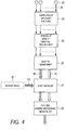
- FIG. 4 illustrates a function of the voice signal processing of the in-vehicle acoustic processing apparatus.
- Each of the functions denoted with the reference numerals 23 to 28 illustrated in FIG. 4 is provided in the microphone module or the head unit as illustrated with FIG. 5 described later.
- the microphone module includes a plurality of acoustic conversion devices 23.
- Acoustic conversion devices 23 receive a voice signal (for example, a mixed sound of noise and a voice of a speaking person), and convert the voice signal into an electric signal.
- a voice signal for example, a mixed sound of noise and a voice of a speaking person
- Sensitivity correction function 24 (which is also referred to as sensitivity correction section) corrects non-uniformity of the sensitivity or the phase of signals received from a plurality of acoustic conversion devices 23, among acoustic conversion devices 23. It is to be noted that, in FIG. 4 and FIG. 5 , sensitivity correction function 24 is illustrated as "correction of sensitivity and phase.”
- Noise removal function 25 (which is also referred to as noise removal section) performs non-correlative component extraction on a signal received from sensitivity correction function 24, and reduces and removes noise of wind, vibration, heat and the like. It is to be noted that, in FIG. 4 and FIG. 5 , noise removal function 25 is illustrated as "removal of noise of vibration, wind and heat.”
- Adaptive beamformer 26 (which is also referred to as adaptive beamformer section) performs a spatial separation of a sound by a directivity control on a signal received from noise removal function 25.
- Echo canceller 27 (which is also referred to as echo canceller section) performs, on a signal received from adaptive beamformer 26, separation of an echo and a voice of a speaking person during a hands-free call for example. When echo cancelling is performed, a speaker signal is required, and therefore speaker signal 32 is input to echo canceller 27.
- Full-time learning multichannel Wiener filter (Mch WF) 28 performs linear or nonlinear computation on a signal received from echo canceller 27 to separate the sound.
- the reference numerals 29, 30, 31 and 33 denote electric signals.
- the reference numeral 29 represents a mixed signal of an object sound (such as a voice of the speaking person) and noise.
- the reference numeral 30 represents a signal containing a large amount of an object sound.
- the reference numeral 31 represents a signal containing a large amount of noise.
- the reference numeral 33 represents a signal input from a speaker.
- FIG. 5 illustrates a configuration in which the functions of the voice signal processing illustrated in FIG. 4 are shared by the microphone module and the head unit.
- FIG. 5 illustrates examples of six types [1] to [6] of sharing of the functions.
- [1] corresponds to a configuration in which only a plurality of acoustic conversion devices are mounted in the microphone module, and sensitivity correction function 24 to full-time learning multichannel Wiener filter 28 illustrated in FIG. 4 are mounted in the head unit.
- the function layout (function allocation) of [1] is commercially available as the function layout of an in-vehicle acoustic processing apparatus.
- [2] to [6] correspond to respective configurations in which at least one of sensitivity correction function 24 to full-time learning multichannel Wiener filter 28 illustrated in FIG. 4 is mounted in the microphone module.
- the in-vehicle acoustic processing apparatus employs any of the function layouts of [2] to [6] of FIG. 5 . Selection from the function layouts of [2] to [6] is made in consideration of the conditions illustrated in FIG. 6 .
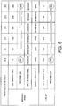
- FIG. 6 illustrates differences in throughput of DSP among the function layouts of [1] to [6] shown in FIG. 5 , and illustrates whether input of a speaker signal to the microphone module is required or not (see FIG. 4 ).
- [MIPS] is the unit representing the processing ability of DSP and is an abbreviation of "Million Instructions Per Second.” It is to be noted that the values of the MIPS of [1] to [6] shown in FIG. 6 are rough estimate values obtained by use of a common DSP, and the values are not limitative.
- the DSP processing load of the microphone module is smallest in [1], and largest in [6].
- the processing load of head unit DSP is largest in [1], and smallest in [6].
- input of a speaker signal to the microphone module is unnecessary in [1] to [4], but necessary in [5] and [6].
- the number of output signals of the microphone module is large in [1] to [3], and small in [4] and [5] relative to [1] to [3], and, minimized in [6] (see the number of output signals in FIG. 5 (the number of arrows)).
- the number of inputs of the head unit that receives a signal of the microphone module change in accordance with the number of output of the microphone module of [1] to [6].
- the function layout of the microphone module and the head unit to be mounted in the vehicle is determined in consideration of conditions of mounting to the vehicle, and the conditions of FIG. 6 .
- FIG. 7 is a schematic view of an in-vehicle acoustic processing apparatus in which a sound (sound pressure) is input to the microphone module and output from a speaker.
- the reference numeral 34 represents an acoustic conversion device itself or the microphone module
- the reference numeral 35 a speaker
- the reference numeral 36 an A/D convertor that converts an analog signal received by microphone module 34 into a digital vibration
- the reference numeral 37 a signal processing section that performs a digital signal processing
- the reference numeral 38 a D/A convertor that converts a digital signal into an analog signal.
- the arrows indicate a flow of an electric signal.
- An analog signal is output in the form of a sound from speaker 35.
- FIG. 7 illustrates an operation in which a voice, which is an analog signal or the like, is once converted into a digital signal (A/D conversion), and a resulting signal of the digital signal processing is converted into an analog signal (D/A conversion).
- a sampling clock is used for the conversion operation of the analog input output apparatus (A/D converter 36 and D/A convertor 38); however, in some situation, the sampling clocks are different among the apparatuses. In view of this, the clock difference is required to be compensated by performing clock synchronization, or by again performing a sampling processing on the transmitted digital signal.
- the sampling frequency is high, clock synchronization via a transmission path such as a cable is difficult to be performed, and therefore an asynchronous communication method is used in digital signal connection in some situation.
- a method using over sampling may be employed to obtain data of another clock in an asynchronous manner from the already digitized signal.
- the microphone module and the head unit are configured with any of the function layouts [2] to [6] illustrated in FIG. 5 , and therefore the accuracy of the processing performed on a voice collected in the interior of the vehicle does not depend on the installation position of the microphone module.
- the accuracy of the processing performed on a voice collected in the interior of the vehicle can be improved.
- the present invention is applicable to in-vehicle acoustic processing apparatuses which are used for hands-free call or voice recognition in the interior of the automobile.
Landscapes
- Engineering & Computer Science (AREA)
- Signal Processing (AREA)
- Health & Medical Sciences (AREA)
- Physics & Mathematics (AREA)
- Acoustics & Sound (AREA)
- Otolaryngology (AREA)
- Combustion & Propulsion (AREA)
- Transportation (AREA)
- Mechanical Engineering (AREA)
- Chemical & Material Sciences (AREA)
- Computational Linguistics (AREA)
- Audiology, Speech & Language Pathology (AREA)
- Human Computer Interaction (AREA)
- Multimedia (AREA)
- Quality & Reliability (AREA)
- General Health & Medical Sciences (AREA)
- Circuit For Audible Band Transducer (AREA)
- Fittings On The Vehicle Exterior For Carrying Loads, And Devices For Holding Or Mounting Articles (AREA)
- Obtaining Desirable Characteristics In Audible-Bandwidth Transducers (AREA)
Abstract
Description
- The present invention relates to an in-vehicle acoustic processing apparatus which is used for hands-free call or voice recognition in the interior of an automobile.
- Voice recognition used for hands-free call or in-vehicle navigation for destination search and the like in the interior of the automobile acoustic is performed with an in-vehicle acoustic processing apparatus including an acoustic conversion device. However, a sound pressure which is taken into an acoustic conversion device contains noises of the interior of the vehicle such as a blower sound (wind noise) of the air-conditioner, an engine sound, a travelling noise in addition to a voice of a speaking person such as a driver and a fellow passenger of a seat other than the driver's seat. Consequently, during hands-free call, the receiver of the call hears the voice of the speaking person mixed with the noise, and therefore it is difficult to make favorable conversation. In addition, regarding the voice recognition, the rate of the voice recognition is reduced.
- To solve such a problem, the following techniques are proposed, for example. For example,
PTLS PTLS PTL 4 discloses a method for mounting a microphone module which can prevent mixture of noise. -
-
PTL 1
Japanese Patent Application Laid-Open No.2001-13994 -
PTL 2
Japanese Patent Application Laid-Open No.2010-283506 -
PTL 3
Japanese Patent Publication No.3146804 -
PTL 4
Japanese Patent Publication No.3936154 - An in-vehicle acoustic processing apparatus is known in which a microphone module is disposed at a position near the speaking person in order to accurately collect a voice of the speaking person, and a head unit provided separately from a plurality of microphone modules performs processing of a voice input to the microphone module. However, the noise in the interior of a vehicle differs depending on the positions. Therefore, a sound input to the microphone module can contain a large amount of noise depending on its position, and as a result the accuracy of the voice processing is disadvantageously reduced.
PTLS 1 to 4 do not disclose a configuration for solving such a problem. - An object of the present invention is to provide an in-vehicle acoustic processing apparatus which can improve the accuracy of processing on a voice collected in the interior of a vehicle.
- An in-vehicle acoustic processing apparatus according to an aspect of the present invention includes: a microphone module installed in an interior of an vehicle; and a head unit disposed at a position separated from the microphone module in the interior of the vehicle. The microphone module includes a plurality of acoustic conversion devices that convert a received voice signal into an electric signal, and a sensitivity correction section that performs, on a signal received from the acoustic conversion devices, correction of non-uniformity in sensitivity among the acoustic conversion devices, and a signal processed by the sensitivity correction section is output to the head unit.
- According to the present invention, it is possible to provide an in-vehicle acoustic processing apparatus which can improve the accuracy of processing on a voice collected in the interior of a vehicle.
-
-
FIG. 1 is a schematic view illustrating an interior of a vehicle in which an in-vehicle acoustic processing apparatus according to an embodiment of the present invention is mounted; -
FIG. 2 is a schematic view illustrating the interior of the vehicle in which the in-vehicle acoustic processing apparatus according to the embodiment of the present invention is mounted; -
FIG. 3A is a perspective view illustrating a configuration of a microphone module according to the embodiment of the present invention; -
FIG. 3B is a sectional view illustrating a configuration of the microphone module according to the embodiment of the present invention; -
FIG. 4 illustrates a function of voice signal processing of the in-vehicle acoustic processing apparatus according to the embodiment of the present invention; -
FIG. 5 illustrates sharing of functions of the voice signal processing according to the embodiment of the present invention; -
FIG. 6 is illustrates differences in throughput of DSP among function layouts of the microphone module and the head unit according to the embodiment of the present invention; and -
FIG. 7 is a schematic view of the in-vehicle acoustic processing apparatus according to the embodiment of the present invention. - An embodiment of the present invention is described below with reference to the drawings.
- First, an installation example of an in-vehicle acoustic processing apparatus according to the present embodiment is described with reference to
FIG. 1. FIG. 1 is a schematic view illustrating an interior of a vehicle in which the in-vehicle acoustic processing apparatus according to the present embodiment is mounted. It is to be noted that whileFIG. 1 illustrates a vehicle with right-hand drive for convenience of description, the vehicle in which the in-vehicle acoustic processing apparatus according to the present embodiment is mounted may also be a vehicle with left-hand drive. In addition, while the vehicle is an automobile in the present embodiment, the vehicle is not limited to an automobile. - As illustrated in
FIG. 1 ,vehicle 1 includeswindshield 2,steering wheel 4, over-head console (OHC) 5, andhead unit 7. Over-headconsole 5 is disposed at the upper left ofdriver 3, that is, at a center portion on the front side on the ceiling in the interior ofvehicle 1. Over-headconsole 5 is provided withpressure entrance hole 6 into which a sound pressure such as a voice of a passenger (such as a driver and a fellow passenger) ofvehicle 1 enters. A microphone module described later (seeFIGS. 2 to 3 ) is disposed on the rear side of soundpressure entrance hole 6. -
Head unit 7 forms the in-vehicle acoustic processing apparatus according to the present embodiment together with the microphone module.Head unit 7 is disposed at a front portion of the driver's seat, and connected with the microphone module with an electric line (not illustrated).Head unit 7 receives a voice signal output from the microphone module. - In the in-vehicle acoustic processing apparatus according to the present embodiment, the microphone module and the head unit are separated from each other, and the microphone module is disposed on the ceiling of the interior of the vehicle. Since the distance between a speaking person (passenger) and the microphone module is small, the above-mentioned configuration can facilitate the performance of the microphone module in comparison with a configuration in which the microphone module is incorporated in the head unit. For example, when the distance between the microphone module and the speaking person is tripled, the S/N ratio of the microphone module is deteriorated by approximately 10 dB (deteriorated in proportion to the logarithm of the distance). In view of this, it is preferable to set the distance between the microphone module and the speaking person to a small value as much as possible, and, from a practical standpoint, it is more preferable to dispose the microphone module on the ceiling in the interior of the vehicle.
- While the microphone module is installed in over-head
console 5 inFIG. 1 , the microphone module may be embedded in the ceiling ofvehicle 1. Also with this configuration, the microphone module can be disposed at a position near the speaking person.FIG. 2 illustrates an example configuration in which the microphone module is embedded in the ceiling of vehicle. - As illustrated in
FIG. 2 ,vehicle 1 includesmicrophone modules 9a to 9f,head unit 10,relaying module 11, andelectric line 12. As withFIG. 1 ,head unit 10 may be disposed at a front portion of the driver's seat, or disposed on the ceiling of the interior ofvehicle 1.Relaying module 11 is an apparatus for relay betweenhead unit 10 andmicrophone modules 9a to 9f. In addition,microphone modules 9a to 9f provided in the proximity of respective seats are connected with relayingmodule 11 throughelectric line 12. In addition, relayingmodule 11 is connected withhead unit 10 throughelectric line 12. With this configuration, in the example illustrated inFIG. 2 , voices received atmicrophone modules 9a to 9f are output to headunit 10 through relayingmodule 11 in the form of voice signals. - The transmission scheme of
electric line 12 betweenmicrophone modules 9a to 9f andhead unit 10 may be an analog transmission scheme, or a digital transmission scheme. It should be noted that in the case where a plurality of microphone modules are provided as illustrated inFIG. 2 , or the case where two or more acoustic devices are provided in the microphone module, it is desirable to use a digital transmission scheme since, in the above-mentioned cases, signal multiplexing can be achieved with a digital transmission scheme. In addition, with use of a digital transmission scheme, clocks can be substantially synchronized between the microphone module and the head unit when echo cancelling is performed as described later, and the performance of the in-vehicle acoustic processing apparatus can be increased in comparison with analog transmission. - I2S, CXPI, LIN, CAN, FlexRay, MOST, IEEE1394 (so-called "FireWire" (registered trademark)), LVDS, USB and the like are desirable as the digital transmission scheme since the above-mentioned schemes are generally used for in-vehicle LAN.
- In addition, in the case where a multiplex transmission scheme (signal multiplexing) is used for exchanging digital signals between
microphone modules 9a to 9f andhead unit 10, the number of the lines can be reduced even when a large number of acoustic conversion devices or microphone modules are used. As a result, the cost of the lines required for mounting the in-vehicle acoustic processing apparatus to the vehicle can be advantageously reduced. - Next, an example configuration of the microphone module described with reference to
FIG. 1 andFIG. 2 is described with reference toFIG. 3A and FIG. 3B. FIG. 3A is a perspective view illustrating a configuration of the microphone module, andFIG. 3B is a sectional view illustrating a configuration of the microphone module. - In
FIG. 3A ,microphone module 13 includesupper case 14. A veil for preventing entrance of foreign matters and the like may be disposed on the top surface ofupper case 14. In addition,microphone module 13 includesholder 15 that holds the acoustic conversion device, andacoustic conversion device 16. While twoacoustic conversion devices 16 are illustrated inFIG. 3A and FIG. 3B , the number ofacoustic conversion devices 16 is not limited to two, and two or moreacoustic conversion devices 16 may be provided. - In addition, while
microphone module 13 illustrated inFIG. 3A and FIG. 3B is an electret capacitor condenser microphone (ECM),microphone module 13 may be of another type such as an acoustic conversion device called MEMS microphone. - In addition,
microphone module 13 includesconnector 17,circuit board 18,connector 19,connector 20, electricelectronic component 21, andbottom case 22.Connector 17 is configured to connectacoustic conversion device 16 tocircuit board 18.Connector 19 is provided oncircuit board 18, and configured for connection ofconnector 17.Connector 20 is configured for outputting an electric signal frommicrophone module 13. A plurality of electricelectronic components 21 are configured to convert a voice signal (sound pressure) input toacoustic conversion device 16, into an electric signal. Electricelectronic component 21 includes a digital signal processor (DSP) that performs an acoustic signal process. - It is to be noted that the format of the output of
connector 20 is not limited, and may be analog output or digital output. In addition,connector 20 may be omitted such that a line for outputting an electric signal is directly connected or joined fromcircuit board 18. - Next, a voice signal processing of the in-vehicle acoustic processing apparatus according to the present embodiment is described with reference to
FIG. 4. FIG. 4 illustrates a function of the voice signal processing of the in-vehicle acoustic processing apparatus. Each of the functions denoted with thereference numerals 23 to 28 illustrated inFIG. 4 is provided in the microphone module or the head unit as illustrated withFIG. 5 described later. - As illustrated in
FIG. 4 , the microphone module includes a plurality ofacoustic conversion devices 23.Acoustic conversion devices 23 receive a voice signal (for example, a mixed sound of noise and a voice of a speaking person), and convert the voice signal into an electric signal. - Sensitivity correction function 24 (which is also referred to as sensitivity correction section) corrects non-uniformity of the sensitivity or the phase of signals received from a plurality of
acoustic conversion devices 23, amongacoustic conversion devices 23. It is to be noted that, inFIG. 4 andFIG. 5 ,sensitivity correction function 24 is illustrated as "correction of sensitivity and phase." - Noise removal function 25 (which is also referred to as noise removal section) performs non-correlative component extraction on a signal received from
sensitivity correction function 24, and reduces and removes noise of wind, vibration, heat and the like. It is to be noted that, inFIG. 4 andFIG. 5 ,noise removal function 25 is illustrated as "removal of noise of vibration, wind and heat." - Adaptive beamformer 26 (which is also referred to as adaptive beamformer section) performs a spatial separation of a sound by a directivity control on a signal received from
noise removal function 25. - Echo canceller 27 (which is also referred to as echo canceller section) performs, on a signal received from
adaptive beamformer 26, separation of an echo and a voice of a speaking person during a hands-free call for example. When echo cancelling is performed, a speaker signal is required, and thereforespeaker signal 32 is input to echocanceller 27. - Full-time learning multichannel Wiener filter (Mch WF) 28 performs linear or nonlinear computation on a signal received from
echo canceller 27 to separate the sound. - In addition, in
FIG. 4 , thereference numerals reference numeral 29 represents a mixed signal of an object sound (such as a voice of the speaking person) and noise. Thereference numeral 30 represents a signal containing a large amount of an object sound. Thereference numeral 31 represents a signal containing a large amount of noise. Thereference numeral 33 represents a signal input from a speaker. - Next, sharing of the functions of the voice signal processing is described.
FIG. 5 illustrates a configuration in which the functions of the voice signal processing illustrated inFIG. 4 are shared by the microphone module and the head unit.FIG. 5 illustrates examples of six types [1] to [6] of sharing of the functions. - In
FIG. 5 , [1] corresponds to a configuration in which only a plurality of acoustic conversion devices are mounted in the microphone module, andsensitivity correction function 24 to full-time learningmultichannel Wiener filter 28 illustrated inFIG. 4 are mounted in the head unit. The function layout (function allocation) of [1] is commercially available as the function layout of an in-vehicle acoustic processing apparatus. - In
FIG. 5 , [2] to [6] correspond to respective configurations in which at least one ofsensitivity correction function 24 to full-time learningmultichannel Wiener filter 28 illustrated inFIG. 4 is mounted in the microphone module. - The in-vehicle acoustic processing apparatus according to the present embodiment employs any of the function layouts of [2] to [6] of
FIG. 5 . Selection from the function layouts of [2] to [6] is made in consideration of the conditions illustrated inFIG. 6 . - Next, conditions which are taken into consideration for selection of the function layouts are described with reference to
FIG. 6. FIG. 6 illustrates differences in throughput of DSP among the function layouts of [1] to [6] shown inFIG. 5 , and illustrates whether input of a speaker signal to the microphone module is required or not (seeFIG. 4 ). InFIG. 6 , [MIPS] is the unit representing the processing ability of DSP and is an abbreviation of "Million Instructions Per Second." It is to be noted that the values of the MIPS of [1] to [6] shown inFIG. 6 are rough estimate values obtained by use of a common DSP, and the values are not limitative. - In
FIG. 6 , the DSP processing load of the microphone module is smallest in [1], and largest in [6]. On the other hand, the processing load of head unit DSP is largest in [1], and smallest in [6]. In addition, input of a speaker signal to the microphone module is unnecessary in [1] to [4], but necessary in [5] and [6]. In addition, the number of output signals of the microphone module is large in [1] to [3], and small in [4] and [5] relative to [1] to [3], and, minimized in [6] (see the number of output signals inFIG. 5 (the number of arrows)). The number of inputs of the head unit that receives a signal of the microphone module change in accordance with the number of output of the microphone module of [1] to [6]. - The function layout of the microphone module and the head unit to be mounted in the vehicle is determined in consideration of conditions of mounting to the vehicle, and the conditions of
FIG. 6 . - Next, a method for performing the echo canceller function without causing failure in the present example is described with reference to
FIG. 7 . -
FIG. 7 is a schematic view of an in-vehicle acoustic processing apparatus in which a sound (sound pressure) is input to the microphone module and output from a speaker. InFIG. 7 , thereference numeral 34 represents an acoustic conversion device itself or the microphone module, the reference numeral 35 a speaker, thereference numeral 36 an A/D convertor that converts an analog signal received bymicrophone module 34 into a digital vibration, the reference numeral 37 a signal processing section that performs a digital signal processing, and the reference numeral 38 a D/A convertor that converts a digital signal into an analog signal. In the drawing, the arrows indicate a flow of an electric signal. An analog signal is output in the form of a sound fromspeaker 35. -
FIG. 7 illustrates an operation in which a voice, which is an analog signal or the like, is once converted into a digital signal (A/D conversion), and a resulting signal of the digital signal processing is converted into an analog signal (D/A conversion). A sampling clock is used for the conversion operation of the analog input output apparatus (A/D converter 36 and D/A convertor 38); however, in some situation, the sampling clocks are different among the apparatuses. In view of this, the clock difference is required to be compensated by performing clock synchronization, or by again performing a sampling processing on the transmitted digital signal. When the sampling frequency is high, clock synchronization via a transmission path such as a cable is difficult to be performed, and therefore an asynchronous communication method is used in digital signal connection in some situation. When sampling is again performed on the digital signal transmitted by asynchronous communication, a method using over sampling may be employed to obtain data of another clock in an asynchronous manner from the already digitized signal. - It is possible to operate the echo canceller function without causing failure by performing clock synchronization among analog input output apparatuses, or by compensating clock difference in the above-mentioned manner.
- As described above, according to the present embodiment, the microphone module and the head unit are configured with any of the function layouts [2] to [6] illustrated in
FIG. 5 , and therefore the accuracy of the processing performed on a voice collected in the interior of the vehicle does not depend on the installation position of the microphone module. Thus, with the present embodiment, the accuracy of the processing performed on a voice collected in the interior of the vehicle can be improved. - The disclosure of the specification, drawings, and abstract in Japanese Patent Application No.
2015-027529 filed on February 16, 2015 - The present invention is applicable to in-vehicle acoustic processing apparatuses which are used for hands-free call or voice recognition in the interior of the automobile.
-
- 1 Vehicle
- 2 Windshield
- 3 Driver
- 4 Steering wheel
- 5 Over-head console
- 6 Sound pressure entrance hole
- 7, 10 Head unit
- 9a, 9b, 9c, 9d, 9e, 9f, 13 Microphone module
- 11 Relaying module
- 12 Electric line
- 14 Upper case
- 15 Holder
- 16, 23 Acoustic conversion device
- 17, 19, 20 Connector
- 18 Circuit board
- 21 Electric electronic component
- 22 Bottom case
- 24 Sensitivity correction function
- 25 Noise removal function
- 26 Adaptive beamformer
- 27 Echo canceller
- 28 Full-time learning multichannel Wiener filter
- 29, 30, 31, 33 Electric signal
- 32 Speaker signal
- 34 Acoustic conversion device or microphone module
- 35 Speaker
- 36 A/D convertor
- 37 Signal processing section
- 38 D/A convertor
Claims (16)
- An in-vehicle acoustic processing apparatus comprising:a microphone module installed in an interior of an vehicle; anda head unit disposed at a position separated from the microphone module in the interior of the vehicle, whereinthe microphone module includesa plurality of acoustic conversion devices that convert a received voice signal into an electric signal, anda sensitivity correction section that performs, on a signal received from the acoustic conversion devices, correction of non-uniformity in sensitivity among the acoustic conversion devices, anda signal processed by the sensitivity correction section is output to the head unit.
- The in-vehicle acoustic processing apparatus according to claim 1, wherein
the microphone module further includes a noise removal section that removes a noise component from the signal processed by the sensitivity correction section, and
a signal processed by the noise removal section is output to the head unit. - The in-vehicle acoustic processing apparatus according to claim 2, wherein
the microphone module further includes an adaptive beamformer section that performs, on the signal processed by the noise removal section, a spatial separation of a sound by a directivity control, and
a signal processed by the adaptive beamformer section is output to the head unit. - The in-vehicle acoustic processing apparatus according to claim 3, wherein
the microphone module further includes an echo canceller section that performs a separation of an echo and a voice on the signal processed by the adaptive beamformer section, and
a signal processed by the echo canceller section is output to the head unit. - The in-vehicle acoustic processing apparatus according to claim 4, wherein
the microphone module further includes a full-time learning multichannel Wiener filter that performs linear or nonlinear computation on the signal processed by the echo canceller section, and
a signal processed by the full-time learning multichannel Wiener filter is output to the head unit. - The in-vehicle acoustic processing apparatus according to claim 1, wherein a connector for digital transmission output is mounted on a circuit board of the microphone module.
- The in-vehicle acoustic processing apparatus according to claim 1, wherein a line cable for digital transmission is mounted on a circuit board of the microphone module.
- The in-vehicle acoustic processing apparatus according to claim 1, wherein the microphone module is mounted in an over-head console or on a ceiling in the interior of the vehicle.
- The in-vehicle acoustic processing apparatus according to claim 1, wherein
the head unit includes:a noise removal section that removes a noise component from a signal received from the microphone module;an adaptive beamformer section that performs, on a signal processed by the noise removal section, a spatial separation of a sound by a directivity control;an echo canceller section that performs a separation of an echo and a voice on a signal processed by the adaptive beamformer section; anda full-time learning multichannel Wiener filter that performs linear or nonlinear computation on a signal processed by the echo canceller section. - The in-vehicle acoustic processing apparatus according to claim 2, wherein
the head unit further includes:an adaptive beamformer section that performs, on a signal received from the microphone module, a spatial separation of a sound by a directivity control;an echo canceller section that performs a separation of an echo and a voice on a signal processed by the adaptive beamformer section; anda full-time learning multichannel Wiener filter that performs linear or nonlinear computation on a signal processed by the echo canceller section. - The in-vehicle acoustic processing apparatus according to claim 3, wherein
the head unit includes:an echo canceller section that performs, on a signal received from the microphone module, a separation of an echo and a voice; anda full-time learning multichannel Wiener filter that performs linear or nonlinear computation on a signal processed by the echo canceller section. - The in-vehicle acoustic processing apparatus according to claim 4, wherein the head unit includes a full-time learning multichannel Wiener filter that performs linear or nonlinear computation on a signal received from the microphone module.
- The in-vehicle acoustic processing apparatus according to claim 1, wherein a signal exchanged between the microphone module and the head unit is an analog signal.
- The in-vehicle acoustic processing apparatus according to claim 1, wherein a signal exchanged between the microphone module and the head unit is a digital signal.
- The in-vehicle acoustic processing apparatus according to claim 14, wherein the signal exchanged between the microphone module and the head unit is transmitted by a multiplex transmission scheme.
- The in-vehicle acoustic processing apparatus according to claim 14, wherein, in a process of inputting and outputting a signal between the microphone module and the head unit, clock synchronization is performed, or, clock difference is compensated.
Applications Claiming Priority (2)
| Application Number | Priority Date | Filing Date | Title |
|---|---|---|---|
| JP2015027529 | 2015-02-16 | ||
| PCT/JP2015/005697 WO2016132409A1 (en) | 2015-02-16 | 2015-11-16 | Vehicle-mounted sound processing device |
Publications (2)
| Publication Number | Publication Date |
|---|---|
| EP3264792A1 true EP3264792A1 (en) | 2018-01-03 |
| EP3264792A4 EP3264792A4 (en) | 2018-04-11 |
Family
ID=56692038
Family Applications (1)
| Application Number | Title | Priority Date | Filing Date |
|---|---|---|---|
| EP15882514.1A Withdrawn EP3264792A4 (en) | 2015-02-16 | 2015-11-16 | Vehicle-mounted sound processing device |
Country Status (5)
| Country | Link |
|---|---|
| US (1) | US20170229136A1 (en) |
| EP (1) | EP3264792A4 (en) |
| JP (1) | JPWO2016132409A1 (en) |
| CN (1) | CN106717023A (en) |
| WO (1) | WO2016132409A1 (en) |
Families Citing this family (2)
| Publication number | Priority date | Publication date | Assignee | Title |
|---|---|---|---|---|
| US11532302B2 (en) * | 2017-09-28 | 2022-12-20 | Harman International Industries, Incorporated | Pre-voice separation/recognition synchronization of time-based voice collections based on device clockcycle differentials |
| KR102559685B1 (en) * | 2018-12-19 | 2023-07-27 | 현대자동차주식회사 | Vehicle and control method for the same |
Family Cites Families (14)
| Publication number | Priority date | Publication date | Assignee | Title |
|---|---|---|---|---|
| JPH0797880B2 (en) * | 1988-07-08 | 1995-10-18 | ソニー株式会社 | Microphone device |
| US6420975B1 (en) * | 1999-08-25 | 2002-07-16 | Donnelly Corporation | Interior rearview mirror sound processing system |
| JP4250421B2 (en) * | 2001-02-14 | 2009-04-08 | ジェンテクス・コーポレーション | Vehicle accessory microphone |
| US7660428B2 (en) * | 2004-10-25 | 2010-02-09 | Polycom, Inc. | Ceiling microphone assembly |
| JP2006319786A (en) * | 2005-05-13 | 2006-11-24 | Sony Corp | Sound field measuring apparatus and sound field measuring method |
| US8112272B2 (en) * | 2005-08-11 | 2012-02-07 | Asashi Kasei Kabushiki Kaisha | Sound source separation device, speech recognition device, mobile telephone, sound source separation method, and program |
| EP1931169A4 (en) * | 2005-09-02 | 2009-12-16 | Japan Adv Inst Science & Tech | POST-FILTER FOR A MICROPHONE MATRIX |
| JP2011135310A (en) * | 2009-12-24 | 2011-07-07 | Daiichikosho Co Ltd | Microphone for setting characteristics by prom cartridge |
| CN102348156A (en) * | 2010-07-29 | 2012-02-08 | 美商富迪科技股份有限公司 | Voice processing apparatus and method thereof |
| CN101937698B (en) * | 2010-07-30 | 2012-07-11 | 奇瑞汽车股份有限公司 | Vehicle-mounted multifunctional integrated application system |
| CN102595281B (en) * | 2011-01-14 | 2016-04-13 | 通用汽车环球科技运作有限责任公司 | The microphone pretreatment system of unified standard and method |
| US9538285B2 (en) * | 2012-06-22 | 2017-01-03 | Verisilicon Holdings Co., Ltd. | Real-time microphone array with robust beamformer and postfilter for speech enhancement and method of operation thereof |
| US9173023B2 (en) * | 2012-09-25 | 2015-10-27 | Intel Corporation | Multiple device noise reduction microphone array |
| CN203933744U (en) * | 2014-05-16 | 2014-11-05 | 比亚迪股份有限公司 | Voice communication noise reduction system and vehicle in a kind of car |
-
2015
- 2015-11-16 US US15/515,350 patent/US20170229136A1/en not_active Abandoned
- 2015-11-16 WO PCT/JP2015/005697 patent/WO2016132409A1/en not_active Ceased
- 2015-11-16 JP JP2017500480A patent/JPWO2016132409A1/en active Pending
- 2015-11-16 EP EP15882514.1A patent/EP3264792A4/en not_active Withdrawn
- 2015-11-16 CN CN201580052745.5A patent/CN106717023A/en active Pending
Also Published As
| Publication number | Publication date |
|---|---|
| CN106717023A (en) | 2017-05-24 |
| JPWO2016132409A1 (en) | 2017-08-10 |
| EP3264792A4 (en) | 2018-04-11 |
| US20170229136A1 (en) | 2017-08-10 |
| WO2016132409A1 (en) | 2016-08-25 |
Similar Documents
| Publication | Publication Date | Title |
|---|---|---|
| KR101103794B1 (en) | Multi Beam Acoustic System | |
| US20160150315A1 (en) | System and method for echo cancellation | |
| CN106611602A (en) | Vehicle sound collection apparatus and sound collection method | |
| CN105592384B (en) | System and method for controlling in-vehicle noise | |
| US8805453B2 (en) | Hands-free telephony and in-vehicle communication | |
| US7369664B2 (en) | Hands-free microphone with wind guard | |
| US10290312B2 (en) | Sound source separation device and sound source separation method | |
| JP3788428B2 (en) | Voice input device for automobile | |
| US20150120305A1 (en) | Speech communication system for combined voice recognition, hands-free telephony and in-car communication | |
| US20120221341A1 (en) | Motor-vehicle voice-control system and microphone-selecting method therefor | |
| EP2966646A9 (en) | System and method for acoustic management | |
| US7035796B1 (en) | System for noise suppression, transceiver and method for noise suppression | |
| WO2001041499A3 (en) | Method and device for improving communication in a vehicle | |
| CN211543441U (en) | Active noise reduction system with low-delay interface | |
| CN105575399A (en) | Systems and methods for selecting audio filtering schemes | |
| US20160119712A1 (en) | System and method for in cabin communication | |
| EP3732680B1 (en) | Acoustical in-cabin noise cancellation system for far-end telecommunications | |
| US12125468B2 (en) | Audio processing system, audio processing device, and audio processing method | |
| KR20160030722A (en) | An apparatus to eliminate a noise of sound, a method for eliminating a noise of a sound, a sound recognition apparatus using the same and a vehicle equipped with the sound recognition apparatus | |
| EP3264792A1 (en) | Vehicle-mounted sound processing device | |
| US10026414B2 (en) | Speech processing system, vehicle, speech processing unit, steering wheel unit, speech processing method, and speech processing program | |
| JP6473972B2 (en) | Audio processing device, audio processing method, audio processing program, audio processing device mounting method, ceiling member, and vehicle | |
| CN113223550A (en) | Real-time call system, control method of real-time call system, and driving device | |
| US12039965B2 (en) | Audio processing system and audio processing device | |
| JP4161685B2 (en) | Audio input / output device |
Legal Events
| Date | Code | Title | Description |
|---|---|---|---|
| PUAI | Public reference made under article 153(3) epc to a published international application that has entered the european phase |
Free format text: ORIGINAL CODE: 0009012 |
|
| 17P | Request for examination filed |
Effective date: 20170316 |
|
| AK | Designated contracting states |
Kind code of ref document: A1 Designated state(s): AL AT BE BG CH CY CZ DE DK EE ES FI FR GB GR HR HU IE IS IT LI LT LU LV MC MK MT NL NO PL PT RO RS SE SI SK SM TR |
|
| AX | Request for extension of the european patent |
Extension state: BA ME |
|
| A4 | Supplementary search report drawn up and despatched |
Effective date: 20180308 |
|
| RIC1 | Information provided on ipc code assigned before grant |
Ipc: H04R 1/02 20060101ALI20180303BHEP Ipc: G06F 9/50 20060101ALN20180303BHEP Ipc: H04R 1/40 20060101ALI20180303BHEP Ipc: H04R 3/02 20060101ALI20180303BHEP Ipc: H04L 7/00 20060101ALN20180303BHEP Ipc: B60R 11/02 20060101ALI20180303BHEP Ipc: H04M 9/08 20060101ALN20180303BHEP Ipc: H04R 3/00 20060101AFI20180303BHEP |
|
| DAV | Request for validation of the european patent (deleted) | ||
| DAX | Request for extension of the european patent (deleted) | ||
| STAA | Information on the status of an ep patent application or granted ep patent |
Free format text: STATUS: THE APPLICATION IS DEEMED TO BE WITHDRAWN |
|
| 18D | Application deemed to be withdrawn |
Effective date: 20181009 |