EP3264736A1 - Image reading apparatus and semiconductor device - Google Patents
Image reading apparatus and semiconductor device Download PDFInfo
- Publication number
- EP3264736A1 EP3264736A1 EP17176701.5A EP17176701A EP3264736A1 EP 3264736 A1 EP3264736 A1 EP 3264736A1 EP 17176701 A EP17176701 A EP 17176701A EP 3264736 A1 EP3264736 A1 EP 3264736A1
- Authority
- EP
- European Patent Office
- Prior art keywords
- signal
- image
- circuit
- image reading
- pixel
- Prior art date
- Legal status (The legal status is an assumption and is not a legal conclusion. Google has not performed a legal analysis and makes no representation as to the accuracy of the status listed.)
- Ceased
Links
Images






Classifications
-
- H—ELECTRICITY
- H04—ELECTRIC COMMUNICATION TECHNIQUE
- H04N—PICTORIAL COMMUNICATION, e.g. TELEVISION
- H04N1/00—Scanning, transmission or reproduction of documents or the like, e.g. facsimile transmission; Details thereof
- H04N1/04—Scanning arrangements, i.e. arrangements for the displacement of active reading or reproducing elements relative to the original or reproducing medium, or vice versa
- H04N1/19—Scanning arrangements, i.e. arrangements for the displacement of active reading or reproducing elements relative to the original or reproducing medium, or vice versa using multi-element arrays
- H04N1/195—Scanning arrangements, i.e. arrangements for the displacement of active reading or reproducing elements relative to the original or reproducing medium, or vice versa using multi-element arrays the array comprising a two-dimensional [2D] array
- H04N1/19594—Scanning arrangements, i.e. arrangements for the displacement of active reading or reproducing elements relative to the original or reproducing medium, or vice versa using multi-element arrays the array comprising a two-dimensional [2D] array using a television camera or a still video camera
-
- H—ELECTRICITY
- H04—ELECTRIC COMMUNICATION TECHNIQUE
- H04N—PICTORIAL COMMUNICATION, e.g. TELEVISION
- H04N1/00—Scanning, transmission or reproduction of documents or the like, e.g. facsimile transmission; Details thereof
- H04N1/00885—Power supply means, e.g. arrangements for the control of power supply to the apparatus or components thereof
- H04N1/00888—Control thereof
- H04N1/00896—Control thereof using a low-power mode, e.g. standby
-
- H—ELECTRICITY
- H04—ELECTRIC COMMUNICATION TECHNIQUE
- H04N—PICTORIAL COMMUNICATION, e.g. TELEVISION
- H04N1/00—Scanning, transmission or reproduction of documents or the like, e.g. facsimile transmission; Details thereof
- H04N1/00885—Power supply means, e.g. arrangements for the control of power supply to the apparatus or components thereof
- H04N1/00904—Arrangements for supplying power to different circuits or for supplying power at different levels
-
- H—ELECTRICITY
- H04—ELECTRIC COMMUNICATION TECHNIQUE
- H04N—PICTORIAL COMMUNICATION, e.g. TELEVISION
- H04N1/00—Scanning, transmission or reproduction of documents or the like, e.g. facsimile transmission; Details thereof
- H04N1/024—Details of scanning heads ; Means for illuminating the original
- H04N1/028—Details of scanning heads ; Means for illuminating the original for picture information pick-up
-
- H—ELECTRICITY
- H04—ELECTRIC COMMUNICATION TECHNIQUE
- H04N—PICTORIAL COMMUNICATION, e.g. TELEVISION
- H04N25/00—Circuitry of solid-state image sensors [SSIS]; Control thereof
- H04N25/70—SSIS architectures; Circuits associated therewith
- H04N25/76—Addressed sensors, e.g. MOS or CMOS sensors
- H04N25/78—Readout circuits for addressed sensors, e.g. output amplifiers or A/D converters
-
- H—ELECTRICITY
- H10—SEMICONDUCTOR DEVICES; ELECTRIC SOLID-STATE DEVICES NOT OTHERWISE PROVIDED FOR
- H10F—INORGANIC SEMICONDUCTOR DEVICES SENSITIVE TO INFRARED RADIATION, LIGHT, ELECTROMAGNETIC RADIATION OF SHORTER WAVELENGTH OR CORPUSCULAR RADIATION
- H10F39/00—Integrated devices, or assemblies of multiple devices, comprising at least one element covered by group H10F30/00, e.g. radiation detectors comprising photodiode arrays
- H10F39/10—Integrated devices
- H10F39/12—Image sensors
- H10F39/198—Contact-type image sensors [CIS]
-
- H—ELECTRICITY
- H04—ELECTRIC COMMUNICATION TECHNIQUE
- H04N—PICTORIAL COMMUNICATION, e.g. TELEVISION
- H04N2201/00—Indexing scheme relating to scanning, transmission or reproduction of documents or the like, and to details thereof
- H04N2201/0077—Types of the still picture apparatus
- H04N2201/0081—Image reader
Definitions
- the present invention relates to an image reading apparatus and a semiconductor device.
- An image reading apparatus (scanner or the like) which uses a contact image sensor, a copy machine in which a print function is added to the image reading apparatus, a complex printer, or the like is developed.
- the contact image sensor used in the image reading apparatus adopts a configuration in which a photodiode provided in a semiconductor substrate is used.
- the image reading apparatus such as a scanner includes a plurality of sensor chips in which a plurality of pixels having one or a plurality of photodiodes are arranged in parallel in one direction.
- JP-A-2001-156989 discloses an image reading apparatus in which photoelectric conversion signals are sequentially read from a plurality of sensor chips and each sensor chip can perform an output operation only during a period from a predetermined time when reading starts to reading ends.
- An advantage of some aspects of the invention is to provide an image reading apparatus and a semiconductor device which can achieve low power consumption.
- an image reading apparatus including a plurality of image reading chips for reading an image, in which each of the plurality of image reading chips includes a pixel that includes a light receiving element which receives light from the image and performs photoelectric conversion, a voltage boosting circuit that generates a transmission control signal for transmitting electric charges which are generated on the basis of the photoelectric conversion that is performed by the light receiving element, and a reading circuit which generates an image signal on the basis of the electric charges which are transmitted and outputs the image signal, and in which the voltage boosting circuit operates during a period in which the light receiving element of the pixel receives the light and during a period in which the electric charges that are generated on the basis of the photoelectric conversion which is performed by the light receiving element are transmitted, and stops an operation during a period in which the reading circuits of the other image reading chips output the image signals.
- a voltage boosting circuit of each of a plurality of image reading chips stops an operation during a period in which reading circuits of the other image reading chips output image signals, and thus, each of the plurality of image reading chips can efficiently operate.
- the image reading apparatus according to the application example it is possible to reduce the total consumption current (a total of the consumption currents) of the plurality of image reading chips, and to achieve low power consumption.
- each of the plurality of image reading chips may operate only in a period in which the reading circuit outputs the image signal.
- a reading circuit of each of a plurality of image reading chips stops an operation during a period in which an image signal is not output, and thus, each of the plurality of image reading chips can operate more efficiently.
- each of the plurality of image reading chips may include a switch that determines whether or not to activate the pixel in response to the transmission control signal, and the electric charges that are generated on the basis of the photoelectric conversion which is performed by the light receiving element may be transmitted through the switch.
- a voltage boosting circuit of each of a plurality of image reading chips stops an operation during a period in which reading circuits of the other image reading chips output image signals, and thus, a transmission control signal is not generated and a pixel also stops an operation.
- each of the plurality of image reading chips can efficiently operate, it is possible to reduce the total consumption current of the plurality of image reading chips, and to achieve low power consumption.
- the reading circuits of each of the plurality of image reading chips may stop operations during a period in which the reading circuits of the other image reading chips output the image signals.
- a reading circuit of each of a plurality of image reading chips stops an operation during a period in which reading circuits of the other image reading chips output image signals, and thus, each of the plurality of image reading chips can efficiently operate.
- each of the plurality of image reading chips may operate in response to a clock signal that is supplied to an input terminal, and propagation of the clock signal may stop during a period in which the voltage boosting circuit and the reading circuit stop operations together.
- the reading circuit of each of the plurality of image reading chips may include a pixel drive circuit that generates a drive signal for reading a signal from the pixel on the basis of the electric charges which are transmitted, and an output circuit that generates the image signal and outputs the image signal.
- a voltage boosting circuit of each of a plurality of image reading chips stops an operation during a period in which pixel drive circuits and output circuits of the other image reading chips operate, and thus, each of the plurality of image reading chips can efficiently operate.
- a semiconductor device including a pixel that includes a light receiving element which receives light and performs photoelectric conversion; a voltage boosting circuit that generates a transmission control signal for transmitting electric charges which are generated on the basis of the photoelectric conversion that is performed by the light receiving element; a reading circuit which generates an image signal on the basis of the electric charges which are transmitted and outputs the image signal; and an input terminal to which a control signal is input, in which the voltage boosting circuit operates during a predetermined period after the control signal is input to the input terminal, and stops an operation during a period after outputting the image signal ends.
- a voltage boosting circuit stops an operation during a period in which outputting an image signal ends, and thus, each of a plurality of image reading chips can efficiently operate. Hence, in the semiconductor device according to the application example, it is possible to reduce the total consumption current of the plurality of image reading chips, and to achieve low power consumption.
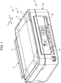
- Fig. 1 is an external perspective view illustrating the complexer 1.
- the complexer 1 includes a printer unit (image recording device) 2 which is a device body, and a scanner unit (image reading apparatus) 3 that is an upper unit disposed in an upper portion of the printer unit 2, as one piece.
- printer unit image recording device
- scanner unit image reading apparatus
- the printer unit 2 includes a transport unit (not illustrated) which feeds a recording medium of sheet (print paper or cut paper) along a feeding path, a print unit (not illustrated) which is disposed on an upper portion of the feeding path and performs print processing on the recording medium by using an ink jet method, an operation unit 63 of a panel type which is disposed on a front surface, another transport unit, a device frame (not illustrated) in which the printer unit and the operation unit 63 are mounted, and a device housing 65 which covers those.
- An outlet 66 through which the recording medium whose printing is completed is discharged is provided in the device housing 65.
- a USB port and a power port which are not illustrated, are disposed in a lower portion of a rear surface. That is, the complexer 1 is configured to be able to be connected to a computer or the like through the USB port.
- the scanner unit 3 is rotatably supported to the printer unit 2 through a hinge unit 4 of a rear end portion, and covers an upper portion of the printer unit 2 to be freely opened and closed. That is, by pulling up the scanner unit 3 in a rotation direction, an opening of an upper surface of the printer unit 2 is exposed, and an internal portion of the printer unit 2 is exposed through the opening of the upper portion. Meanwhile, by pulling down the scanner unit 3 in the rotation direction to mount on the printer unit 2, the opening of the upper portion is closed by the scanner unit 3. As such, by opening the scanner unit 3, it is possible to provide a configuration for replacing an ink cartridge, solving paper jam, and the like.
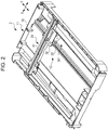
- Fig. 2 is a perspective view illustrating an internal structure of the scanner unit 3.
- the scanner unit 3 includes an upper frame 11 which is a housing, an image reading unit 12 accommodated in the upper frame 11, an upper cover 13 rotatably supported to an upper portion of the upper frame 11.
- the upper frame 11 includes a box-shaped lower case 16 which accommodates the image reading unit 12, and an upper case 17 which covers a top surface of the lower case 16.
- a document mounting plate (document table: not illustrated) made of glass is widely disposed on the upper case 17, and a medium to be read (document) with a surface to be read facing down is mounted thereon.
- the lower case 16 is formed in a shallow box shape with an open upper surface.
- the image reading unit 12 includes a sensor unit 31 of a line sensor type, a sensor carriage 32 on which the sensor unit 31 is mounted, a guide shaft 33 which extends in the Y-axis direction and slidably supports the sensor carriage 32, and a self-propelled sensor moving mechanism 34 which moves the sensor carriage 32 along the guide shaft 33.
- the sensor unit 31 includes an image sensor module 41 which is a complementary metal-oxide-semiconductor (CMOS) line sensor extending in the X-axis direction, and performs reciprocation by the motor-driven sensor moving mechanism 34 along the guide shaft 33 in the Y-axis direction. Thereby, an image of the medium to be read (document) on the document mounting plate is read.
- CMOS complementary metal-oxide-semiconductor
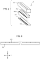
- Fig. 3 is an exploded perspective view schematically illustrating a configuration of the image sensor module 41.
- the image sensor module 41 is configured to include a case 411, a light source 412, a lens 413, a module substrate 414, and an image reading chip 415 (semiconductor device) for reading an image.
- the light source 412, the lens 413, and the image reading chip 415 are accommodated between the case 411 and the module substrate 414.
- a slit is provided in the case 411.
- the light source 412 includes each light emitting diode (LED) of, for example, R, G, and B, and makes each light emitting diode (red LED, green LED, and blue LED) of R, G, and B sequentially emit light while switching at high speed.
- the light source 412 irradiates the medium to be read with light through the slit, and the light from the medium to be read is incident on the lens 413 through the slit.
- the lens 413 guides the light which is incident to the image reading chip 415.
- Fig. 4 is a plan view schematically illustrating arrangement of the image reading chips 415. As illustrated in Fig. 4 , a plurality of (m pieces) the image reading chips 415 is arranged in parallel on the module substrate 414 in a one-dimensional direction (X-axis direction in Fig. 4 ). Each image reading chip 415 includes multiple light receiving elements which are arranged in a column (refer to Figs. 6 and 8 ), and the higher the density of the light receiving elements included in the image reading chip 415 is, the higher the resolution of the scanner unit 3 (image reading apparatus) for reading an image that can be realized. In addition, the larger the number of the image reading chips 415 is, the larger the image that the scanner unit 3 (image reading apparatus) can read.
- Fig. 5 is a functional block diagram illustrating a functional configuration example of the scanner unit 3 (image reading apparatus).
- the scanner unit (image reading apparatus) 3 is configured to include a control unit 200, an analog front end (AFE) 202, a red LED 412R, a green LED 412G, a blue LED 412B, and m image reading chips 415 (415-1 to 415-m).
- the red LED 412R, the green LED 412G, and the blue LED 412B are included in the light source 412, and a plurality of the image reading chips 415 is arranged on the module substrate 414.
- Each of the red LED 412R, the green LED 412G, and the blue LED 412B may be plural.
- the control unit 200 and the analog front end (AFE) 202 are included in a substrate (not illustrated) different from the module substrate 414.
- Each of the control unit 200 and the analog front end (AFE) 202 may be realized by an integrated circuit (IC).
- the control unit 200 supplies a drive signal DrvR to the red LED 412R only during a predetermined exposure time ⁇ t in a predetermined period T, and makes the red LED 412R emit light.
- the control unit 200 makes the green LED 412G emit light by supplying a drive signal DrvG to the green LED 412G only during the exposure time ⁇ t in the period T, and makes the blue LED 412B emit light by supplying a drive signal DrvB to the blue LED 412B only during the exposure time ⁇ t in the period T.
- the control unit 200 makes the red LED 412R, the green LED 412G, and the blue LED 412B exclusively and sequentially emit light by one during the period T.
- control unit 200 commonly supplies a clock signal CLK and a resolution setting signal RES to the m image reading chips 415 (415-1 to 415-m).
- the clock signal CLK is an operation clock signal of the m image reading chips 415, and each of the m image reading chips 415 operates on the basis of the clock signal CLK.
- the resolution setting signal RES sets a resolution of an image which is read by the scanner unit (image reading apparatus) 3. The resolution is set by the number of rising edges of the clock signal CLK during a period in which the resolution setting signal RES is active (high level in the present embodiment).
- each resolution of 300 dpi, 600 dpi, and 1200 dpi is set, in a case where the number of the rising edges of the clock signal CLK is 2, 4, and 8 during the period in which the resolution setting signal RES is active (high level), in the present embodiment.
- the control unit 200 after making the red LED 412R, the green LED 412G, or the blue LED 412B emit light, the control unit 200 generates the chip enable signal EN1 which is active (high level) for a predetermined time (time until the image reading chip 415-1 outputs the image signal SO) to supply to the image reading chip 415-1.
- the red LED 412R, the green LED 412G, or the blue LED 412B emits light
- the m image reading chips 415 (415-1 to 415-m) sequentially output the image signals SO.
- a detailed circuit configuration and an operation of the image reading chip 415 will be described below.
- the analog front end (AFE) 202 receives the image signals SO which are sequentially output from the m image reading chips 415 (415-1 to 415-m), performs amplification processing or A/D conversion processing for each image signal SO, converts the processed signals into digital signals having digital values corresponding to the amount of received light of each light receiving element, and sequentially transmits each digital signal to the control unit 200.
- AFE analog front end
- the control unit 200 receives each digital signal which is sequentially transmitted from the analog front end (AFE) 202, and generates image information that the image sensor module 41 reads.
- AFE analog front end
- Fig. 6 is a functional block diagram of the image reading chip 415.
- the image reading chip 415 illustrated in Fig. 6 includes a control circuit 100, a voltage boosting circuit 111, a pixel drive circuit 112, n pixels 110, and an output circuit 120.
- the image reading chip 415 includes two power supply terminals VDP and VSP to which a power supply voltage VDD (for example, 3.3 V) and a power supply voltage VSS (for example, 0 V) are respectively supplied, and operates on the basis of a chip enable signal EN_I (one of the chip enable signals EN1 to ENm of Fig. 5 ), the resolution setting signal RES, and the clock signal CLK which are respectively input through three input terminals IP1, IP2, and IP3, and a reference voltage VREF which is supplied through a reference voltage supply terminal VRP.
- VDD for example, 3.3 V
- VSS for example, 0 V
- the chip enable signal EN_I, the resolution setting signal RES, and the clock signal CLK are input to the control circuit 100 through input buffers 113, 114, and 115 respectively.
- the control circuit 100 controls operations of the voltage boosting circuit 111, the pixel drive circuit 112, the n pixels 110, and the output circuit 120, and an operation of an output buffer 116 in response to the chip enable signal EN_I, the resolution setting signal RES, and the clock signal CLK.
- control circuit 100 generates a control signal CPC which controls the voltage boosting circuit 111, a control signal DRC which control the pixel drive circuit 112, a control signal CDSC which controls a correlated double sampling (CDS) circuit 121 included in the output circuit 120, a sampling signal SMP which controls an amplification circuit 122 included in the output circuit 120, a pixel selection signal SEL0 which controls the pixel 110, a reset signal RST, a second transmission control signal Tx2 (Tx2a, Tx2b, Tx2c, Tx2d), and a chip enable signal EN_O which controls the output buffer 116.
- CPC control signal which controls the voltage boosting circuit 111
- DRC which control the pixel drive circuit 112
- CDSC which controls a correlated double sampling (CDS) circuit 121 included in the output circuit 120
- sampling signal SMP which controls an amplification circuit 122 included in the output circuit 120
- SEL0 which controls the pixel 110
- reset signal RST a second transmission control signal T
- the voltage boosting circuit 111 boosts a voltage of the power supply voltage VDD in response to the control signal CPC from the control circuit 100, and generates a first transmission control signal Tx1 which sets the boosted power supply voltage to a high level.
- the first transmission control signal Tx1 is a control signal for transmitting electric charges (electric charges accumulated in the light receiving element) generated on the basis of photoelectric conversion which is performed by the light receiving element during the exposure time ⁇ t, and is commonly supplied to the n pixels 110.
- the pixel drive circuit 112 generates the drive signal Drv which drives the n pixels 110, based on the control signal DRC from the control circuit 100.
- the n pixels 110 are provided in parallel in one-dimensional direction, and the drive signal Drv is transmitted to the n pixels 110 by the drive signal lines 311.
- the ith (i is one of 1 to n) pixel 110 outputs an output signal (pixel signal) by making a pixel selection signal SELi active (high level), when the drive signal Drv is active (high level) and the pixel selection signal SELi-1 is active (high level).
- the pixel selection signal SELi is output to the (i+1)th pixel 110.
- the n pixels 110 include the light receiving elements which receive light from an image formed in a medium to be read and perform photoelectric conversion, and output pixel signals of voltages corresponding to the light that the light receiving elements receive during the exposure time ⁇ t in response to the first transmission control signal Tx1, the second transmission control signal Tx2, the pixel selection signal SEL (one of SEL0 to SELn-1), the reset signal RST, and the drive signal Drv, respectively.
- Output signals (pixel signals) which are output from the n pixels 110 are sequentially transmitted to the output circuit 120 through an output signal line 301.
- the n pixels 110 all have the same configuration, and a specific circuit configuration and an operation thereof will be described below.
- the output circuit 120 generates and outputs the image signal SO by performing predetermined signal processing for the pixel signals which are output from each of the n pixels 110.
- the output circuit 120 includes a CDS circuit 121 and an amplification circuit 122.
- the CDS circuit 121 receives an image signal Vo which sequentially includes the pixel signals that are respectively output from the n pixels 110 through the output signal line 301, and operates on the basis of the control signal CDSC from the control circuit 100.
- the CDS circuit 121 removes noise which is caused by characteristic variation of amplification transistors included in the n pixels 110 and is superimposed on the image signal Vo, by performing correlated double sampling based on the reference voltage VREF. That is, the CDS circuit 121 is a noise reduction circuit which reduces noise included in the output signals (pixel signals) which are output from the n pixels 110.
- the amplification circuit 122 samples a signal whose noise is removed by the CDS circuit 121 in response to the sampling signal SMP, amplifies the sampled signal, and generates the image signal SO. That is, the amplification circuit 122 amplifies the output signals (pixel signals) which are output from the n pixels 110.
- the image signal SO is output from the image reading chip 415 through an output terminal OP1, and is supplied to the analog front end (AFE) 202 (refer to Fig. 5 ).
- a circuit including the pixel drive circuit 112 and the output circuit 120 functions as a reading circuit 130 which generates and outputs the image signal SO, based on electric charges which are generated on the basis of photoelectric conversion that is performed by the light receiving elements and which are transmitted by the first transmission control signal Tx1 and the second transmission control signal Tx2, in the pixel 110.
- the control circuit 100 generates the chip enable signal EN_O (one of the chip enable signals EN2 to ENm+1 of Fig. 5 ) which is a signal of a high pulse shortly before an output of the image signal SO from the output circuit 120 ends, and outputs the generated signal to the image reading chip 415 in a next stage from an output terminal OP2 through the output buffer 116. Thereafter, the control circuit 100 stops the outputting the image signal SO from the output circuit 120, and drives an output terminal OP1 to high impedance.
- EN_O one of the chip enable signals EN2 to ENm+1 of Fig. 5
- Fig. 7 is a diagram illustrating a configuration example of the control circuit 100.
- the control circuit 100 includes a timing signal generation circuit 101, a voltage boosting control circuit 102, a pixel drive control circuit 103, a CDS control circuit 104, an amplification control circuit 105, an enable control circuit 106, and an output end determination circuit 107.
- the control circuit 100 includes a NOT circuit 141 and four AND circuits 142, 143, 144, and 145.
- the timing signal generation circuit 101 samples the resolution setting signal RES at timing when the clock signal CLK rises, and continuously counts the number of sampling of the resolution setting signal RES of a high level, in a case where the sampled resolution setting signal RES is in a high level.
- the timing signal generation circuit 101 retains bit data indicating each resolution of 300 dpi if the counted value is 2, 600 dpi if the counted value is 4, and 1200 dpi if the counted value is 8, in a resolution setting register (not illustrated).
- the timing signal generation circuit 101 includes a timer (counter) (not illustrated) which operates in response to the clock signal CLK, and generates timing signals TMCP, TMDR, TMCDS, and TMAMP, based on the bit data retained in the resolution setting register and a value of the timer.
- a timer (counter) (not illustrated) which operates in response to the clock signal CLK, and generates timing signals TMCP, TMDR, TMCDS, and TMAMP, based on the bit data retained in the resolution setting register and a value of the timer.
- the timing signal generation circuit 101 receives the chip enable signal EN_I (high pulse), generates the pixel selection signal SEL0 which is active (high level in the present embodiment) for a predetermined time, and outputs the generated signal to the first pixel 110.
- the timing signal generation circuit 101 outputs the pixel selection signal SEL0, and thereafter, generates the reset signal RST which initializes electric charges that are accumulated in the n pixels 110 at predetermined timing.
- the reset signal RST is commonly supplied to the n pixels 110.
- the image reading chip 415 includes a control signal line 300 for transmitting the reset signal RST to the n pixels 110.
- the voltage boosting control circuit 102 receives the timing signal TMCP, and outputs a control signal CPCX for controlling the voltage boosting circuit 111 at predetermined timing.
- a control signal which is output from the voltage boosting control circuit 102 may be a clock signal for voltage boosting which is performed by the voltage boosting circuit 111.
- the pixel drive control circuit 103 receives the timing signal TMDR and generates the second transmission control signal Tx2.
- the second transmission control signal Tx2 is configured with four signals Tx2a, Tx2b, Tx2c, and Tx2d, and a signal which is active (high level in the present embodiment) changes in accordance with the bit data which is retained in the resolution setting register.
- the bit data indicates a resolution of 1200 dpi
- only the signal Tx2a becomes active (high level) in first one cycle of the clock signal CLK
- only the signal Tx2b becomes active (high level) in second one cycle
- only the signal Tx2c becomes active (high level) in third one cycle
- only the signal Tx2d becomes active (high level) in fourth one cycle, among the second transmission control signals Tx2.
- the bit data indicates a resolution of 600 dpi
- only two signals Tx2a and Tx2b simultaneously become active (high level) in one cycle of the clock signal CLK
- only two signals Tx2c and Tx2d simultaneously become active (high level) in next one cycle, among the second transmission control signals Tx2.
- the four signals Tx2a, Tx2b, Tx2c, and Tx2d of the second transmission control signal Tx2 simultaneously become active (high level) in one cycle of the clock signal CLK.
- the pixel drive control circuit 103 receives the timing signal TMDR and outputs a control signal DRCX for controlling the pixel drive circuit 112 at predetermined timing.
- the CDS control circuit 104 receives the timing signal TMCDS and outputs a control signal CDSCX for controlling the CDS circuit 121 at predetermined timing.
- the amplification control circuit 105 receives the timing signal TMAMP and outputs a sampling signal SMPX for controlling the amplification circuit 122 at predetermined timing.
- the enable control circuit 106 receives a timing signal TMEN and generates the chip enable signal EN_O at predetermined timing.
- the output end determination circuit 107 determines whether or not an output of the image signal SO from the reading circuit 130 (output circuit 120) ends, based on the bit data retained in the resolution setting register included in the timing signal generation circuit 101 and the value of the timer included therein, and outputs an end signal END which is active (high level in the present embodiment) in a case where it is determined that the output ends. In addition, the output end determination circuit 107 makes the end signal END inactive (low level) if a pulse of the resolution setting signal RES is input.
- the end signal END is inactive (low level) until outputting the image signal SO ends after the pulse of the resolution setting signal RES is input, and is active (high level) until next pulse of the resolution setting signal RES is input after outputting the image signal SO ends.
- the NOT circuit 141 outputs an enable signal ENB which is obtained by inverting a logic level of the end signal END that is output from the output end determination circuit 107.
- the enable signal ENB is in a high level until outputting the image signal SO ends after a pulse of the resolution setting signal RES is input, and is in a low level until the pulse of the resolution setting signal RES is input after outputting the image signal SO ends.
- the AND circuit 142 outputs a signal which is obtained by performing logical product of the control signal CPCX that is output from the voltage boosting control circuit 102 and the enable signal ENB, and an output signal of the AND circuit 142 is supplied to the voltage boosting circuit 111 as the control signal CPC.
- the AND circuit 143 outputs a signal which is obtained by performing logical product of the control signal DRCX that is output from the pixel drive control circuit 103 and the enable signal ENB, and an output signal of the AND circuit 143 is supplied to the pixel drive circuit 112 as the control signal DRC.
- the AND circuit 144 outputs a signal which is obtained by performing logical product of the control signal CDSCX that is output from the CDS control circuit 104 and the enable signal ENB, and an output signal of the AND circuit 144 is supplied to the CDS circuit 121 as the control signal CDSC.
- the AND circuit 145 outputs a signal which is obtained by performing logical product of the sampling signal SMPX that is output from amplification control circuit 105 and the enable signal ENB, and an output signal of the AND circuit 145 is supplied to the amplification circuit 122 as the sampling signal SMP.
- the enable signal ENB is in a high level, that is, from when the pulse of the resolution setting signal RES is input until outputting the image signal SO ends
- the control signal CPCX, the control signal DRCX, the control signal CDSCX, and the sampling signal SMPX respectively propagate through the AND circuit 142, the AND circuit 143, the AND circuit 144, and the AND circuit 145, thereby, respectively becoming the control signal CPC, the control signal DRC, the control signal CDSC, and the sampling signal SMP.
- the voltage boosting circuit 111 and the reading circuit 130 operate.
- the enable signal ENB is in a low level, that is, from when outputting the image signal SO ends until the pulse of the resolution setting signal RES is input
- the control signal CPC, the control signal DRC, the control signal CDSC, and the sampling signal SMP are all fixed to a low level, and thereby, the voltage boosting circuit 111 and the reading circuit 130 (pixel drive circuit 112 and output circuit 120) stop operating.
- the voltage boosting circuit 111 and the reading circuit 130 operate for a predetermined period (period until outputting the image signal SO ends) after the resolution setting signal RES (an example of the "control signals") is input, and stop the operation for the period after outputting the image signal SO ends.
- Fig. 8 is a diagram illustrating a configuration of the pixel 110 (ith pixel 110). As illustrated in Fig. 8 , the pixel 110 includes four the light receiving elements PD1, PD2, PD3, and PD4. That is, the pixel 110 includes four pixels.
- the light receiving elements PD1, PD2, PD3, and PD4 receive light (light from an image formed in a medium to be read, in the present embodiment) and perform conversion (photoelectric conversion) of the light into electrical signals.
- the light receiving elements PD1, PD2, PD3, and PD4 are configured with photodiodes, and anodes thereof are grounded.
- a cathode of the light receiving element PD1 is connected to a source of an NMOS transistor M11
- a cathode of the light receiving element PD2 is connected to a source of an NMOS transistor M12
- a cathode of the light receiving element PD3 is connected to a source of an NMOS transistor M13
- a cathode of the light receiving element PD4 is connected to a source of an NMOS transistor M14.
- a drain of the NMOS transistor M11 is connected to a source of the NMOS transistor M21, a drain of the NMOS transistor M12 is connected to a source of the NMOS transistor M22, a drain of the NMOS transistor M13 is connected to a source of the NMOS transistor M23, and a drain of the NMOS transistor M14 is connected to a source of the NMOS transistor M24.
- Each gate of the four NMOS transistors M11, M12, M13, and M14 receives the first transmission control signal Tx1.
- the NMOS transistors M11, M12, M13, and M14 function as switches which determine whether or not to be turned on in response to the first transmission control signal Tx1.
- Each drain of the four NMOS transistors M21, M22, M23, and M24 is commonly connected to a source of an NMOS transistor M3, a gate of an NMOS transistor M4, and one terminal of a capacitor C0. The other terminal of the capacitor C0 is grounded.
- a gate of the NMOS transistor M21 receives the signal Tx2a
- a gate of the NMOS transistor M22 receives the signal Tx2b
- a gate of the NMOS transistor M23 receives the signal Tx2c
- a gate of the NMOS transistor M24 receives the signal Tx2d.
- a drain of the NMOS transistor M3 receives a power supply voltage, and a gate of the NMOS transistor M3 receives the reset signal RST.
- a drain of the NMOS transistor M4 receives the power supply voltage, and a source of the NMOS transistor M4 is connected to a drain of an NMOS transistor M5.
- a source of the NMOS transistor M5 is connected to the output signal line 301, and a gate of the NMOS transistor M5 receives an output signal (pixel selection signal SELi) of a flip-flop (F/F).
- the flip-flop (F/F) receives the pixel selection signal SELi-1 and the drive signal Drv, the pixel selection signal SELi-1 is input at the time of rising edge of the drive signal Drv, and the flip-flop outputs the delayed pixel selection signal SELi.
- the pixel selection signal SELi becomes an asynchronous reset signal of the flip-flop (F/F) through an unillustrated delay circuit. Accordingly, the pixel selection signal SELi becomes inactive (low level) after a predetermined time passes after becoming active (high level).
- the ith pixel 110 configured in this way operates as below.
- the first transmission control signal Tx1, the second transmission control signal Tx2 (Tx2a, Tx2b, Tx2c, and Tx2d), the pixel selection signal SELi-1, and the drive signal Drv are all inactive (low level), during the exposure time ⁇ t, and the light receiving elements PD1, PD2, PD3, and PD4 accumulate the electric charges (negative electric charges) corresponding to the received light.
- the electric charges (electric charges accumulated in the light receiving element PD1 (negative electric charges)) which are generated on the basis of the photoelectric conversion that is performed by the light receiving element PD1 are transmitted to an intermediate capacitor C1 (not illustrated) formed at a connection node between the drain of the NMOS transistor M11 and the source of the NMOS transistor M21 through the NMOS transistor M11, and are accumulated therein.
- the electric charges (electric charges accumulated in the light receiving element PD2 (negative electric charges)) which are generated on the basis of the photoelectric conversion that is performed by the light receiving element PD2 are transmitted to an intermediate capacitor C2 (not illustrated) formed at a connection node between the drain of the NMOS transistor M12 and the source of the NMOS transistor M22 through the NMOS transistor M12, and are accumulated therein.
- the electric charges (electric charges accumulated in the light receiving element PD3 (negative electric charges)) which are generated on the basis of the photoelectric conversion that is performed by the light receiving element PD3 are transmitted to an intermediate capacitor C3 (not illustrated) formed at a connection node between the drain of the NMOS transistor M13 and the source of the NMOS transistor M23 through the NMOS transistor M13, and are accumulated therein.
- the electric charges (electric charges accumulated in the light receiving element PD4 (negative electric charges)) which are generated on the basis of the photoelectric conversion that is performed by the light receiving element PD4 are transmitted to an intermediate capacitor C4 (not illustrated) formed at a connection node between the drain of the NMOS transistor M14 and the source of the NMOS transistor M24 through the NMOS transistor M14, and are accumulated therein.
- the first transmission control signal Tx1 becomes inactive (low level), and the drive signal Drv which is supplied to the pixel 110 repeats an active state (high level) and an inactive state (low level) at each time of a half cycle of the clock signal CLK.
- the reset signal RST becomes active (high level) for a predetermined time at each cycle of the clock signal CLK.
- the NMOS transistor M3 is turned on, the capacitor C0 is initialized, and a predetermined amount of electric charges (positive electric charges) are accumulated in the capacitor C0.
- the reset signal RST returns to an inactive state (low level) and thereafter, at least one of the four signals Tx2a, Tx2b, Tx2c, and Tx2d which configure the second transmission control signal Tx2 becomes active (high level) for a predetermined time.
- the signal Tx2a becomes active (high level) for a predetermined time during one cycle of the clock signal CLK.
- the signal Tx2b becomes active (high level) for a predetermined time during one cycle of the clock signal CLK.
- the signal Tx2c becomes active (high level) for a predetermined time during one cycle of the clock signal CLK.
- the signal Tx2d becomes active (high level) for a predetermined time during one cycle of the clock signal CLK.
- the four signals Tx2a, Tx2b, Tx2c, and Tx2d repeat this.
- the four signals Tx2a, Tx2b, Tx2c, and Tx2d simultaneously become active (high level) for a predetermined time during one cycle of the clock signal CLK, and this is repeated.
- At least one of the four signals Tx2a, Tx2b, Tx2c, and Tx2d becomes active (high level) for a predetermined time at least one of the four NMOS transistors M21, M22, M23, and M24 is turned on, and a predetermined amount of electric charges (positive electric charges) accumulated in the capacitor C0 reduces by the amount of electric charges (negative electric charges) accumulated in at least one of the intermediate capacitors C1, C2, C3, and C4.
- the pixel selection signal SELi-1 becomes active (high level) for a predetermined time
- the reset signal RST returns to an inactive state (low level)
- the pixel selection signal SELi becomes active (high level) for a predetermined time.
- the NMOS transistor M5 is turned on, and a current flowing through the NMOS transistor M4 changes depending on the electric charges accumulated in the capacitor C0. Thereby, a source potential of the NMOS transistor M4 changes, and a pixel signal of a voltage according to the source potential of the NMOS transistor M4 is output to the output signal line 301 from the pixel 110.
- the pixel selection signal SELi-1 maintains an inactive state (low level) in the pixel 110 which is not a read target of the pixel signal
- the pixel selection signal SELi is also in a low level.
- the NMOS transistor M5 is turned off, and the pixel signal is not output from the pixel 110.
- An output of the voltage boosting circuit 111 is used for gate signals of the four NMOS transistors M11, M12, M13, and M14 so as to efficiently transmit the electric charges in a short time.
- Fig. 9 is a timing chart of each signal of the image reading chip 415.
- Fig. 9 is a timing chart in a case where a resolution of an image which is read by the scanner unit (image reading apparatus) 3 is set to 300 dpi.
- the resolution setting signal RES first goes to a high level during two cycles of the clock signal CLK. If the exposure time ⁇ t passes, various signals at 300 dpi are supplied to each pixel 110 hereafter.
- the first transmission control signal Tx1 becomes active (high level) during several cycles of the clock signal CLK.
- the pixel selection signal SEL0 becomes active (high level) during one cycle of the clock signal CLK.
- the drive signal Drv becomes active (high level) and the first transmission control signal Tx1 and the pixel selection signal SEL0 become inactive (low level) together.
- the reset signal RST becomes active (high level) in a short time with a slight delay.
- the four signals Tx2a, Tx2b, Tx2c, and Tx2d which configure the second transmission control signal Tx2 are all active (high level) until the clock signal CLK falls next time.
- the pixel selection signal SEL1 becomes active (high level), and thereby, the pixel signal from the first pixel 110 is output to the output signal line 301, and an image signal Vo becomes a voltage according to the pixel signal.
- Signal processing of the image signal Voltage is performed by the output circuit 120, and the image signal SO becomes a voltage corresponding to a first pixel signal in synchronization with falling of the sampling signal SMP.
- the drive signal Drv becomes active (high level), and the pixel selection signal SEL1 becomes inactive (low level).
- the reset signal RST becomes active (high level) in a short time with a slight delay.
- the four signals Tx2a, Tx2b, Tx2c, and Tx2d are active (high level) until the clock signal CLK falls next time.
- the pixel selection signal SEL2 becomes active (high level), and thereby, the pixel signal from the second pixel 110 is output to the output signal line 301 and the image signal Vo becomes a voltage according to the pixel signal.
- Signal processing of the image signal Vo is performed by the output circuit 120, and the image signal SO becomes a voltage corresponding to a second pixel signal in synchronization with falling of the sampling signal SMP.
- the drive signal Drv becomes active (high level), and the pixel selection signal SEL2 becomes inactive (low level).
- the reset signal RST becomes active (high level) in a short time with a slight delay.
- the image signal SO becomes voltages according to third to nth pixel signals in synchronization with falling of the sampling signal SMP in the same manner as above.
- the chip enable signal EN_O (high pulse) is output, and if outputting the image signal SO ends, the output terminal OP1 goes to high impedance.
- Fig. 10 is a timing chart schematically illustrating changes of a signal waveform and a consumption current of each of each of the m image reading chips 415-1 to 415-m while the scanner unit (image reading apparatus) 3 according to the first embodiment reads an image.
- the m image reading chips 415-1, 415-2, ..., 415-m are denoted as chip 1, chip 2, ..., chip m.
- the voltage boosting circuits 111 and the reading circuit 130s (pixel drive circuits 112 and output circuits 120) of each of the image reading chips 415-1 to 415-m operate while the enable signal ENB is in a high level, and stop operations while the enable signal ENB is in a low level.
- the voltage boosting circuit 111 and the reading circuit 130 in the image reading chip 415-1 (chip 1) stops an operation from when outputting the image signal SO ends until the next resolution setting signal RES is input, that is, while the image reading chips 415-2 to 415-m (chip 2 to chip m) sequentially output the image signals SO, and thus, the consumption current of the image reading chip 415-1 (chip 1) decreases during this period.
- the voltage boosting circuit 111 and the reading circuit 130 in the image reading chip 415-2 (chip 2) stops an operation from when outputting the image signal SO ends until the next resolution setting signal RES is input, that is, while the image reading chips 415-3 to 415-m (chip 3 to chip m) sequentially output the image signals SO, and thus, the consumption current of the image reading chip 415-2 (chip 2) decreases during this period. Since the image reading chips 415-3 to 415-m (chip 3 to chip m) are also the same as above, the consumption current of the image reading chip 415-1 decreases the most, the consumption current of the image reading chip 415-2 decreases second to the most, and the consumption current of the image reading chip 415-m becomes the largest.
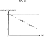
- Fig. 11 is a diagram schematically illustrating a change of total consumption current of the m image reading chips 415-1 to 415-m during a period in which an image of one line is read.
- a horizontal axis denotes time
- a vertical axis denotes a consumption current.
- the total consumption current is approximately constant as l 0 .
- all the voltage boosting circuit 111 and the reading circuit 130 of each of the m image reading chips 415-1 to 415-m in the scanner unit (image reading apparatus) 3 according to the first embodiment operate shortly after reading an image starts and thereby, the total consumption current is l 0 , but as time passes, the number of the voltage boosting circuits 111 and the reading circuits 130 which stop an operation increases and thereby, the total consumption current decreases to l 1 in a stepwise pattern, as denoted by a solid line of Fig. 11 .
- an effect of consumption current reduction is obtained, and the greater the number (number of pixels) of image reading chips 415 is, the larger the effect of consumption current reduction is.
- the image reading chips 415 are used for the scanner unit (image reading apparatus) 3 which can correspond to an A4 size, and many image reading chips 415 are used for the scanner unit (image reading apparatus) 3 which can correspond to an A3 size, and thus, the consumption current can be significantly reduced.
- the scanner unit (image reading apparatus) 3 stops the operations of the voltage boosting circuit 111 and the reading circuit 130 during a period when the reading circuit 130 ends outputting the image signal, in each of the m image reading chips 415-1 to 415-m. Furthermore, if the voltage boosting circuit 111 stops an operation, the second transmission control signal Tx2 is not generated, and the n pixels 110 also stop operations. Hence, each of the m image reading chips 415-1 to 415-m can be efficiently operated by the scanner unit (image reading apparatus) 3 or image reading chips according to the first embodiment, and thus, it is possible to reduce the total consumption current of the m image reading chips 415-1 to 415-m and to achieve low power consumption. Since low power consumption can be achieved, it is also possible to realize the scanner unit (image reading apparatus) 3 which can be used for an operation which is performed by receiving power through the universal serial bus (USB) or for a mobile device.
- USB universal serial bus
- the scanner unit (image reading apparatus) 3 determines whether or not an output end determination circuit 107 stops outputting the image signal SO in each of the m image reading chips 415-1 to 415-m, and, if determining that outputting the image signal ends, stops the operations of the pixel 110, the voltage boosting circuit 111 and the reading circuit 130, and thus, control signals for stopping the pixel 110, the voltage boosting circuit 111, and the reading circuit 130 need not to be input from the outside of the chip. Accordingly, it is possible to prevent development cost or a development period from increasing due to addition of external components, a wiring change of a substrate, an increase of the size of the substrate, and the like.
- a total area of a circuit necessary for stopping the operations of the pixel 110, the voltage boosting circuit 111, and the reading circuit 130 is significantly small, and thus, it is also possible to realize each of the m image reading chips 415-1 to 415-m without increasing a size thereof.
- the scanner unit (image reading apparatus) 3 can achieve low power consumption, it is also possible to add another function such as constantly sensing insertion of paper by using the power which is saved, and to realize, for example, a high function or high reliability.
- a structure of the complexer 1 according to the second embodiment is the same as in the first embodiment ( Figs. 1 to 4 ), and thus, illustration and description thereof will be omitted.
- a functional block diagram of the scanner unit (image reading apparatus) 3 according to the second embodiment is the same as in the first embodiment ( Fig. 5 ), and thus, illustration and description thereof will be omitted.
- a functional block diagram of the image reading chip 415 according to the second embodiment is the same as in the first embodiment ( Fig. 6 ), and thus, illustration and description thereof will be omitted.
- a configuration of the control circuit 100 in the image reading chip 415 according to the second embodiment is different from that in the first embodiment.
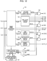
- Fig. 12 is a diagram illustrating a configuration example of the control circuit 100 according to the second embodiment.
- an operation end determination circuit 108 replaces the output end determination circuit 107 of the control circuit 100 ( Fig. 7 ) according to the first embodiment, and an operation start determination circuit 109 and a NOT circuit 146 are added to the control circuit.
- the operation end determination circuit 108 determines whether or not a predetermined period passes which includes a period until the second transmission control signal Tx2 is output from at least the control circuit 100 after a pulse of the resolution setting signal RES is input, based on a value of a timer included in the timing signal generation circuit 101, and outputs an end signal END1 which is active (high level in the present embodiment) in a case where it is determined that the predetermined time passes.
- the operation end determination circuit 108 determines whether or not outputting the image signal SO from the reading circuit 130 (output circuit 120) ends, based on bit data retained in a resolution setting register included in a timing signal generation circuit 101 and the value of the timer, and outputs an end signal END2 which is active (high level in the present embodiment) in a case where it is determined the outputting ends.
- the operation start determination circuit 109 If the pulse of the resolution setting signal RES is input, the operation start determination circuit 109 outputs a start signal ST1 to the operation end determination circuit 108.
- the operation end determination circuit 108 makes the end signal END1 inactive (low level) if receiving the start signal ST1. That is, in the present embodiment, the end signal END1 becomes inactive (low level) during a predetermined period after the pulse of the resolution setting signal RES is input, and becomes active (high level) during a period until the pulse of the resolution setting signal RES is input after the predetermined period passes.
- the operation start determination circuit 109 outputs a start signal ST2 to the operation end determination circuit 108.
- the operation end determination circuit 108 makes the end signal END2 inactive (low level) if receiving the start signal ST2. That is, in the present embodiment, the end signal END2 becomes inactive (low level) during a predetermined period until outputting the image signal SO ends after the chip enable signal EN_I (high pulse) is input, and becomes active (high level) during a period until the chip enable signal EN_I (high pulse) is input after outputting the image signal SO ends.
- the NOT circuit 141 outputs an enable signal ENB1 which is obtained by inverting a logic level of the end signal END1 that is output from the operation end determination circuit 108.
- the enable signal ENB1 is in a high level during a predetermined period after the pulse of the resolution setting signal RES is input, and is in a low level during a period until the pulse of the resolution setting signal RES is input after a predetermined time passes.
- the NOT circuit 146 outputs an enable signal ENB2 which is obtained by inverting a logic level of the end signal END2 that is output from the operation end determination circuit 108.
- the enable signal ENB2 is in a high level during a period until outputting the image signal SO ends after the chip enable signal EN_I (signal with a high pulse) is input, and is in a low level during a period until the next chip enable signal EN_I (signal with a high pulse) is input after outputting the image signal SO end.
- the AND circuit 142 outputs a signal which is obtained by performing logical product of the control signal CPCX which is output from the voltage boosting control circuit 102 and the enable signal ENB1, and an output signal of the AND circuit 142 is supplied to the voltage boosting circuit 111 as the control signal CPC.
- the AND circuit 143 outputs a signal which is obtained by performing logical product of the control signal DRCX that is output from the pixel drive control circuit 103 and the enable signal ENB2, and an output signal of the AND circuit 143 is supplied to the pixel drive circuit 112 as the control signal DRC.
- the AND circuit 144 outputs a signal which is obtained by performing logical product of the control signal CDSCX that is output from the CDS control circuit 104 and the enable signal ENB2, and an output signal of the AND circuit 144 is supplied to the CDS circuit 121 as the control signal CDSC.
- the AND circuit 145 outputs a signal which is obtained by performing logical product of the sampling signal SMPX that is output from the amplification control circuit 105 and the enable signal ENB2, and an output signal of the AND circuit 145 is supplied to the amplification circuit 122 as the sampling signal SMP.
- the control signal CPCX becomes the control signal CPC by propagating through the AND circuit 142, and thereby, the voltage boosting circuit 111 operates.
- the enable signal ENB1 is in a low level, that is, during a period until the pulse of the resolution setting signal RES is input after a predetermined time passes, the control signal CPC is fixed to a low level, and thereby, the voltage boosting circuit 111 stops the operation.
- the voltage boosting circuit 111 operates during a predetermined period after the resolution setting signal RES (an example of the "control signal”) is input to the input terminal IP2, and stops the operation during a period after outputting the image signal SO ends.
- the enable signal ENB2 is in a high level, that is, during a period until outputting the image signal SO ends after the chip enable signal EN_I (signal with a high pulse) is input
- the control signal DRCX, the control signal CDSCX, and the sampling signal SMPX respectively propagate through the AND circuit 143, the AND circuit 144, and the AND circuit 145, thereby, becoming the control signal DRC, the control signal CDSC, and the sampling signal SMP. Accordingly, the reading circuit 130 (the pixel drive circuit 112 and the output circuit 120) operate.
- the enable signal ENB2 is in a low level, that is, during a period until the chip enable signal EN_I (signal with a high pulse) is input after outputting the image signal SO ends, the control signal DRC, the control signal CDSC, and the sampling signal SMP are fixed to a low level, and thereby, the reading circuit 130 (the pixel drive circuit 112 and the output circuit 120) stop the operations.
- Fig. 13 is a timing chart schematically illustrating changes of a signal waveform and a consumption current of each of the m image reading chips 415-1 to 415-m while the scanner unit (image reading apparatus) 3 according to the second embodiment reads an image.
- the m image reading chips 415-1, 415-2, ..., 415-m are denoted as chip 1, chip 2, ..., chip m.
- the voltage boosting circuit 111 in each of the image reading chips 415-1 to 415-m operates while the enable signal ENB1 is in a high level, and stops the operation while the enable signal ENB1 is in a low level.
- the reading circuit 130 (the pixel drive circuit 112 and the output circuit 120) operates while the enable signal ENB2 is in a high level, and stops the operation while the enable signal ENB2 is in a low level.
- the voltage boosting circuits 111 in the image reading chips 415-1 to 415-m operate during a period after the resolution setting signal RES is input. That is, the voltage boosting circuit 111 operates at least during a period in which the light receiving elements PD1, PD2, PD3, and PD4 of the pixel 110 receive light, and during a period in which electric charges generated on the basis of photoelectric conversion that is performed by the light receiving elements PD1, PD2, PD3, and PD4 are transmitted by the first transmission control signal Tx1.
- the voltage boosting circuits 111 in the image reading chips 415-1 to 415-m stop the operations during a period between the time when predetermined time passes after the resolution setting signal RES is input and the time when the next resolution setting signal RES is input.
- the voltage boosting circuit 111 of the image reading chip 415-1 stops the operation at least during a period in which the reading circuits 130 of the other (m-1) image reading chips 415-2 to 415-m output the image signals SO, as illustrated in Fig. 13 .
- the voltage boosting circuit 111 of the image reading chip 415-2 stops the operation at least during a period in which the reading circuits 130 of the other (m-1) image reading chips 415-1, 415-3 to 415-m output the image signals SO
- the voltage boosting circuit 111 of the image reading chip 415-m stops the operation at least during a period in which the other reading circuits 130 of the (m-1) image reading chip 415-1 to 415-(m-1) output the image signals SO.
- the voltage boosting circuits 111 of the image reading chips 415-1 to 415-m stop the operations all the time while the image signals SO are output, and thus, the consumption currents of the image reading chips 415-1 to 415-m (chip 1 to chip m) are reduced.
- the reading circuit 130 in each of the image reading chips 415-1 to 415-m stops the operation during a period from when outputting the image signal SO stops until after the chip enable signal EN_I (signal with a high pulse) is input, that is, during a period in which the reading circuits 130 of the other (m-1) image reading chips 415 output the image signals SO, and operates only the period in which the image signal SO is output. Accordingly, the consumption currents of the image reading chips 415-1 to 415-m (chip 1 to chip m) are significantly reduced.
- Fig. 14 is a diagram schematically illustrating a change of total consumption current of the m image reading chips 415-1 to 415-m during a period in which an image of one line is read, according to the second embodiment.
- a horizontal axis denotes time and a vertical axis denotes a consumption current.
- a dashed line denotes an overview (refer to Fig. 11 ) of a change of the total consumption current according to the first embodiment.
- the reading circuits 130 (whose consumption currents are considerably larger than that of the voltage boosting circuit 111) of each of the m image reading chips 415-1 to 415-m in the scanner unit (image reading apparatus) 3 according to the second embodiment exclusively operate (a plurality of reading circuits 130 does not simultaneously operate) (refer to Fig. 13 ), and thus, the total consumption current maintains an approximately constant current value I 1 .
- the second embodiment an effect in which a consumption current is reduced more than that in the first embodiment is obtained, and the larger the number (the number of pixels) of image reading chips 415 is, the larger the effect in which the consumption current is reduced is.
- the pixel 110, the voltage boosting circuit 111, and the reading circuit 130 stop operations, during a period in which the reading circuits 130 of the other image reading chips 415 output the image signals SO, among the m image reading chips 415-1 to 415-m in the scanner unit (image reading apparatus) 3 according to the second embodiment. Accordingly, each of the m image reading chips 415-1 to 415-m can efficiently operate. Furthermore, the reading circuits 130 of the m image reading chips 415-1 to 415-m in the scanner unit (image reading apparatus) 3 according to the second embodiment stop the operations during the period in which the image signal SO is not output, and thus each of the m image reading chips 415-1 to 415-m can operate more efficiently. Hence, according to the scanner unit (image reading apparatus) 3 of the second embodiment, it is possible to reduce the total consumption current of the m image reading chips 415-1 to 415-m more than that in the first embodiment, and to achieve the lower power consumption.
- the operation end determination circuit 108 of each of the m image reading chips 415-1 to 415-m in the scanner unit (image reading apparatus) 3 according to the second embodiment determines whether or not a predetermined period passes after the pulse of the resolution setting signal RES is input, and in a case where it is determined that the predetermined period passes, the pixel 110 and the voltage boosting circuit 111 stop operations. Accordingly, it is not necessary for control signals for stopping the operations of the pixel 110 and the voltage boosting circuit 111 to be input from the outside.
- the operation end determination circuit 108 determines whether or not outputting the image signal SO ends, and stops the operation of reading circuit 130 in a case where it is determined that outputting the signal ends.
- a control signal for stopping an operation of the reading circuit 130 it is not necessary for a control signal for stopping an operation of the reading circuit 130 to be input from the outside.
- a control signal for stopping an operation of the reading circuit 130 it is possible to prevent development cost or a development period from increasing due to addition of external components, a wiring change of a substrate, an increase of the size of the substrate, and the like.
- a total area of a circuit necessary for stopping the operations of the pixel 110, the voltage boosting circuit 111, and the reading circuit 130 is significantly small, and thus, it is also possible to realize each of the m image reading chips 415-1 to 415-m without increasing a size thereof.
- the same symbols or reference numerals will be attached to the same configuration elements as in the first or second embodiment, description overlapping with the first or second embodiment will be omitted, and description different from the first or second embodiment will be mainly made.
- a structure of the complexer 1 according to the third embodiment is the same as in the first embodiment ( Figs. 1 to 4 ), and thus, illustration and description thereof will be omitted.
- a functional block diagram of the scanner unit (image reading apparatus) 3 according to the third embodiment is the same as in the first embodiment ( Fig. 5 ), and thus, illustration and description thereof will be omitted.
- Fig. 15 is a functional block diagram of an image reading chip 415 according to the third embodiment.
- an AND circuit 117 replaces the input buffer 115 of the image reading chip 415 according to the first embodiment ( Fig. 6 ).
- the AND circuit 117 outputs a clock signal CLK1 that is a signal being obtained by performing logical product of the clock signal CLK which is inputted through the input terminal IP3 and an enable signal CLKEN which is output from the control circuit 100.
- the enable signal CLKEN goes to a high level
- the clock signal CLK propagates through the AND circuit 117 to become the clock signal CLK1
- the enable signal CLKEN goes to a low level
- the clock signal CLK1 is fixed to a low level.
- the clock signal CLK1 becomes an operation clock signal of the control circuit 100.
- the control circuit 100 operates in response to the clock signal CLK1 when the enable signal CLKEN goes to a high level, and stops the operation when the enable signal CLKEN goes to a low level.
- the Fig. 16 is a diagram illustrating a configuration example of the control circuit 100 according to the third embodiment. As illustrated in Fig. 16 , an OR circuit 147 is added to the control circuit 100 according to the third embodiment, compared with the control circuit 100 ( Fig. 12 ) according to the second embodiment.
- the OR circuit 147 outputs a signal that is obtained by performing logical sum of the enable signal ENB1 and the enable signal ENB2, and an output signal of the OR circuit 147 is supplied to the AND circuit 117 (refer to Fig. 15 ) as the enable signal CLKEN.
- the enable signal CLKEN goes to a high level when one or both of the enable signal ENB1 and the enable signal ENB2 go to a high level, and goes to a low level when both of the enable signal ENB1 and the enable signal ENB2 go to a low level.
- the enable signal CLKEN goes to a high level during a predetermined period (period in which the voltage boosting circuit 111 operates) after a pulse of the resolution setting signal RES is input and during a period (period in which the reading circuit 130 operates) from after the chip enable signal EN_I (signal with a high pulse) is input until outputting the image signal SO ends, and the clock signal CLK propagates through the AND circuit 117 to be output as the clock signal CLK1.
- propagation of the clock signal CLK as the clock signal CLK1 is stopped by the AND circuit 117.
- Fig. 17 is a timing chart schematically illustrating changes of a signal waveform and a consumption current of each of the m image reading chips 415-1 to 415-m, while the scanner unit (image reading apparatus) 3 according to the third embodiment reads an image.
- the m image reading chips 415-1, 415-2,..., 415-m are denoted as chip 1, chip 2, ..., chip m.
- the voltage boosting circuits 111 of each of the m image reading chips 415-1 to 415-m operate while the enable signal ENB1 is in a high level, and stop operations while the enable signal ENB1 is in a low level.
- the reading circuits 130 (pixel drive circuits 112 and output circuits 120) operate while the enable signal ENB2 is in a high level, and stop the operations while the enable signal ENB2 is in a low level.
- the clock signal CLK is input to the AND circuit 117, and thus, consumption currents of the image reading chips 415-1 to 415-m (chip 1 to chip m) are greatly reduced.
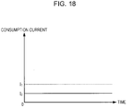
- Fig. 18 is a diagram schematically illustrating a change of total consumption current of the m image reading chips 415-1 to 415-m during a period in which an image of one line is read, in the third embodiment.
- a horizontal axis denotes time and a vertical axis denotes a consumption current.
- a dashed line denotes an overview (refer to Fig. 14 ) of the change of the total consumption current according to the second embodiment.
- the reading circuits 130 of each of the m image reading chips 415-1 to 415-m in the scanner unit (image reading apparatus) 3 according to the third embodiment exclusively operate (a plurality of reading circuits 130 does not simultaneously operate) (refer to Fig. 17 ), the clock signal CLK does not propagate during a period in which the voltage boosting circuit 111 and the reading circuit 130 stop operation together, and thus, the total consumption current is smaller than a current value l 1 and maintains an approximately constant current value l 2 .
- an effect in which a consumption current is reduced more than that in the second embodiment is obtained, and the larger the number (the number of pixels) of image reading chips 415 is, the larger the effect in which the consumption current is reduced is.
- the scanner unit (image reading apparatus) 3 of the third embodiment As described above, according to the scanner unit (image reading apparatus) 3 of the third embodiment, the same effects as in the second embodiment are obtained.
- propagation of the clock signal CLK which is supplied to the input terminal IP3 to the control circuit 100 stops while the pixels 110, the voltage boosting circuits 111, and the reading circuits 130 stop operations, and thus, it is possible to reduce a large consumption current necessary for propagating the clock signal CLK.
- the scanner unit (image reading apparatus) 3 according to the third embodiment it is possible to further reduce the total consumption current of the m image reading chips 415-1 to 415-m than that of the second embodiment, and to achieve lower power consumption.
- the invention includes substantially the same configuration (for example, a configuration in which a function, a method, and results are the same, or a configuration in which an object and effects are the same) as the configuration described in the embodiments.
- the invention includes a configuration in which a non-essential part of the configuration described in the embodiments is replaced.
- the invention includes a configuration which obtains the same operational effects as those of the configuration described in the embodiments, or a configuration which can achieve the same object.
- the invention includes a configuration in which a known technology is added to the configuration described in the embodiments.
Landscapes
- Engineering & Computer Science (AREA)
- Multimedia (AREA)
- Signal Processing (AREA)
- Facsimile Heads (AREA)
- Facsimile Scanning Arrangements (AREA)
- Solid State Image Pick-Up Elements (AREA)
- Image Input (AREA)
Abstract
Description
- The present invention relates to an image reading apparatus and a semiconductor device.
- An image reading apparatus (scanner or the like) which uses a contact image sensor, a copy machine in which a print function is added to the image reading apparatus, a complex printer, or the like is developed. The contact image sensor used in the image reading apparatus adopts a configuration in which a photodiode provided in a semiconductor substrate is used. The image reading apparatus such as a scanner includes a plurality of sensor chips in which a plurality of pixels having one or a plurality of photodiodes are arranged in parallel in one direction.
- For example,
JP-A-2001-156989 - According to the image reading apparatus described in
JP-A-2001-156989 JP-A-2001-156989 - An advantage of some aspects of the invention is to provide an image reading apparatus and a semiconductor device which can achieve low power consumption.
- The invention can be realized in the following aspects or application examples. Application Example 1
- According to this application example, there is provided an image reading apparatus including a plurality of image reading chips for reading an image, in which each of the plurality of image reading chips includes a pixel that includes a light receiving element which receives light from the image and performs photoelectric conversion, a voltage boosting circuit that generates a transmission control signal for transmitting electric charges which are generated on the basis of the photoelectric conversion that is performed by the light receiving element, and a reading circuit which generates an image signal on the basis of the electric charges which are transmitted and outputs the image signal, and in which the voltage boosting circuit operates during a period in which the light receiving element of the pixel receives the light and during a period in which the electric charges that are generated on the basis of the photoelectric conversion which is performed by the light receiving element are transmitted, and stops an operation during a period in which the reading circuits of the other image reading chips output the image signals.
- In the image reading apparatus according to this application example, a voltage boosting circuit of each of a plurality of image reading chips stops an operation during a period in which reading circuits of the other image reading chips output image signals, and thus, each of the plurality of image reading chips can efficiently operate. Hence, in the image reading apparatus according to the application example, it is possible to reduce the total consumption current (a total of the consumption currents) of the plurality of image reading chips, and to achieve low power consumption.
- In the image reading apparatus according to the application example, each of the plurality of image reading chips may operate only in a period in which the reading circuit outputs the image signal.
- In the image reading apparatus according to the application example, a reading circuit of each of a plurality of image reading chips stops an operation during a period in which an image signal is not output, and thus, each of the plurality of image reading chips can operate more efficiently. Hence, in the image reading apparatus according to the application example, it is possible to reduce the total consumption current of the plurality of image reading chips, and to achieve the lower power consumption.
- In the image reading apparatus according to the application example, each of the plurality of image reading chips may include a switch that determines whether or not to activate the pixel in response to the transmission control signal, and the electric charges that are generated on the basis of the photoelectric conversion which is performed by the light receiving element may be transmitted through the switch.
- In the image reading apparatus according to the application example, a voltage boosting circuit of each of a plurality of image reading chips stops an operation during a period in which reading circuits of the other image reading chips output image signals, and thus, a transmission control signal is not generated and a pixel also stops an operation. Hence, in the image reading apparatus according to the application example, since each of the plurality of image reading chips can efficiently operate, it is possible to reduce the total consumption current of the plurality of image reading chips, and to achieve low power consumption.
- In the image reading apparatus according to the application example, the reading circuits of each of the plurality of image reading chips may stop operations during a period in which the reading circuits of the other image reading chips output the image signals.
- In the image reading apparatus according to the application example, a reading circuit of each of a plurality of image reading chips stops an operation during a period in which reading circuits of the other image reading chips output image signals, and thus, each of the plurality of image reading chips can efficiently operate. Hence, in the image reading apparatus according to the application example, it is possible to reduce the total consumption current of the plurality of image reading chips, and to achieve low power consumption.
- In the image reading apparatus according to the application example, each of the plurality of image reading chips may operate in response to a clock signal that is supplied to an input terminal, and propagation of the clock signal may stop during a period in which the voltage boosting circuit and the reading circuit stop operations together.
- In the image reading apparatus according to the application example, propagation of a clock signal which is supplied to an input terminal to an internal circuit stops during a period in which a voltage boosting circuit and a reading circuit stop operations together, in each of a plurality of image reading chips, and thus, a large consumption current necessary for propagating the clock signal can be reduced. Hence, in the image reading apparatus according to the application example, it is possible to further reduce the total consumption current of the plurality of image reading chips, and to achieve the lower power consumption.
- In the image reading apparatus according to the application example, the reading circuit of each of the plurality of image reading chips may include a pixel drive circuit that generates a drive signal for reading a signal from the pixel on the basis of the electric charges which are transmitted, and an output circuit that generates the image signal and outputs the image signal.
- In the image reading apparatus according to the application example, a voltage boosting circuit of each of a plurality of image reading chips stops an operation during a period in which pixel drive circuits and output circuits of the other image reading chips operate, and thus, each of the plurality of image reading chips can efficiently operate. Hence, in the image reading apparatus according to the application example, it is possible to reduce the total consumption current of the plurality of image reading chips, and to achieve low power consumption. Application Example 7
- According to this application example, there is provided a semiconductor device including a pixel that includes a light receiving element which receives light and performs photoelectric conversion; a voltage boosting circuit that generates a transmission control signal for transmitting electric charges which are generated on the basis of the photoelectric conversion that is performed by the light receiving element; a reading circuit which generates an image signal on the basis of the electric charges which are transmitted and outputs the image signal; and an input terminal to which a control signal is input, in which the voltage boosting circuit operates during a predetermined period after the control signal is input to the input terminal, and stops an operation during a period after outputting the image signal ends.
- In the semiconductor device according to the application example, a voltage boosting circuit stops an operation during a period in which outputting an image signal ends, and thus, each of a plurality of image reading chips can efficiently operate. Hence, in the semiconductor device according to the application example, it is possible to reduce the total consumption current of the plurality of image reading chips, and to achieve low power consumption.
- Embodiments of the invention will now be described by way of example only with reference to the accompanying drawings, wherein like numbers reference like elements.
-
Fig. 1 is an external perspective view illustrating a complexer according to the present embodiment. -
Fig. 2 is a perspective view illustrating an internal structure of a scanner unit. -
Fig. 3 is an exploded perspective view schematically illustrating a configuration of an image sensor module. -
Fig. 4 is a plan view schematically illustrating arrangement of image reading chips. -
Fig. 5 is a diagram illustrating a functional configuration example of a scanner unit. -
Fig. 6 is a functional block diagram of the image reading chip. -
Fig. 7 is a diagram illustrating a configuration example of a control circuit. -
Fig. 8 is a diagram illustrating a configuration of a pixel. -
Fig. 9 is a timing chart of each signal of the image reading chip. -
Fig. 10 is a timing chart schematically illustrating changes of a signal waveform and a consumption current of each of m image reading chips. -
Fig. 11 is a diagram schematically illustrating a change of total consumption current of the m image reading chips during a period in which an image of one line is read. -
Fig. 12 is a diagram illustrating a configuration example of a control circuit according to a second embodiment. -
Fig. 13 is a timing chart schematically illustrating changes of a signal waveform and a consumption current of each of m image reading chips according to the second embodiment. -
Fig. 14 is a diagram schematically illustrating a change of total consumption current of the m image reading chips during a period in which an image of one line is read, according to the second embodiment. -
Fig. 15 is a functional block diagram of an image reading chip according to a third embodiment. -
Fig. 16 is a diagram illustrating a configuration example of a control circuit according to the third embodiment. -
Fig. 17 is a timing chart schematically illustrating changes of a signal waveform and a consumption current of each of m image reading chips, in the third embodiment. -
Fig. 18 is a diagram schematically illustrating a change of total consumption current of the m image reading chips during a period in which an image of one line is read, in the third embodiment. - Hereinafter, appropriate embodiments of the invention will be described in detail by using the drawings. The drawings which are used are for the sake of convenience of description. The embodiments which will be described below are not intended to unduly limit content of the invention described in the scope of claims. In addition, all the configurations which will be described below are not necessarily essential components of the invention.
- Hereinafter, a complexer (complex device) 1 applied to an image reading apparatus according to the present embodiment will be described with reference to the accompanying drawings.
-
Fig. 1 is an external perspective view illustrating thecomplexer 1. As illustrated inFig. 1 , thecomplexer 1 includes a printer unit (image recording device) 2 which is a device body, and a scanner unit (image reading apparatus) 3 that is an upper unit disposed in an upper portion of theprinter unit 2, as one piece. Hereinafter, description will be made by setting a front-back direction as an X-axis direction and a left-right direction as a Y-axis direction, inFig. 1 . - Meanwhile, as illustrated in
Fig. 1 , theprinter unit 2 includes a transport unit (not illustrated) which feeds a recording medium of sheet (print paper or cut paper) along a feeding path, a print unit (not illustrated) which is disposed on an upper portion of the feeding path and performs print processing on the recording medium by using an ink jet method, anoperation unit 63 of a panel type which is disposed on a front surface, another transport unit, a device frame (not illustrated) in which the printer unit and theoperation unit 63 are mounted, and adevice housing 65 which covers those. Anoutlet 66 through which the recording medium whose printing is completed is discharged is provided in thedevice housing 65. In addition, a USB port and a power port, which are not illustrated, are disposed in a lower portion of a rear surface. That is, thecomplexer 1 is configured to be able to be connected to a computer or the like through the USB port. - The
scanner unit 3 is rotatably supported to theprinter unit 2 through ahinge unit 4 of a rear end portion, and covers an upper portion of theprinter unit 2 to be freely opened and closed. That is, by pulling up thescanner unit 3 in a rotation direction, an opening of an upper surface of theprinter unit 2 is exposed, and an internal portion of theprinter unit 2 is exposed through the opening of the upper portion. Meanwhile, by pulling down thescanner unit 3 in the rotation direction to mount on theprinter unit 2, the opening of the upper portion is closed by thescanner unit 3. As such, by opening thescanner unit 3, it is possible to provide a configuration for replacing an ink cartridge, solving paper jam, and the like. -
Fig. 2 is a perspective view illustrating an internal structure of thescanner unit 3. As illustrated inFigs. 1 and2 , thescanner unit 3 includes anupper frame 11 which is a housing, animage reading unit 12 accommodated in theupper frame 11, anupper cover 13 rotatably supported to an upper portion of theupper frame 11. As illustrated inFig. 2 , theupper frame 11 includes a box-shapedlower case 16 which accommodates theimage reading unit 12, and anupper case 17 which covers a top surface of thelower case 16. A document mounting plate (document table: not illustrated) made of glass is widely disposed on theupper case 17, and a medium to be read (document) with a surface to be read facing down is mounted thereon. Meanwhile, thelower case 16 is formed in a shallow box shape with an open upper surface. - As illustrated in
Fig. 2 , theimage reading unit 12 includes asensor unit 31 of a line sensor type, asensor carriage 32 on which thesensor unit 31 is mounted, aguide shaft 33 which extends in the Y-axis direction and slidably supports thesensor carriage 32, and a self-propelledsensor moving mechanism 34 which moves thesensor carriage 32 along theguide shaft 33. Thesensor unit 31 includes animage sensor module 41 which is a complementary metal-oxide-semiconductor (CMOS) line sensor extending in the X-axis direction, and performs reciprocation by the motor-drivensensor moving mechanism 34 along theguide shaft 33 in the Y-axis direction. Thereby, an image of the medium to be read (document) on the document mounting plate is read. -
Fig. 3 is an exploded perspective view schematically illustrating a configuration of theimage sensor module 41. In an example illustrated inFig. 3 , theimage sensor module 41 is configured to include acase 411, alight source 412, alens 413, amodule substrate 414, and an image reading chip 415 (semiconductor device) for reading an image. Thelight source 412, thelens 413, and theimage reading chip 415 are accommodated between thecase 411 and themodule substrate 414. A slit is provided in thecase 411. Thelight source 412 includes each light emitting diode (LED) of, for example, R, G, and B, and makes each light emitting diode (red LED, green LED, and blue LED) of R, G, and B sequentially emit light while switching at high speed. Thelight source 412 irradiates the medium to be read with light through the slit, and the light from the medium to be read is incident on thelens 413 through the slit. Thelens 413 guides the light which is incident to theimage reading chip 415. -
Fig. 4 is a plan view schematically illustrating arrangement of the image reading chips 415. As illustrated inFig. 4 , a plurality of (m pieces) theimage reading chips 415 is arranged in parallel on themodule substrate 414 in a one-dimensional direction (X-axis direction inFig. 4 ). Eachimage reading chip 415 includes multiple light receiving elements which are arranged in a column (refer toFigs. 6 and8 ), and the higher the density of the light receiving elements included in theimage reading chip 415 is, the higher the resolution of the scanner unit 3 (image reading apparatus) for reading an image that can be realized. In addition, the larger the number of theimage reading chips 415 is, the larger the image that the scanner unit 3 (image reading apparatus) can read. -
Fig. 5 is a functional block diagram illustrating a functional configuration example of the scanner unit 3 (image reading apparatus). In an example illustrated inFig. 5 , the scanner unit (image reading apparatus) 3 is configured to include acontrol unit 200, an analog front end (AFE) 202, ared LED 412R, agreen LED 412G, ablue LED 412B, and m image reading chips 415 (415-1 to 415-m). As described above, thered LED 412R, thegreen LED 412G, and theblue LED 412B are included in thelight source 412, and a plurality of theimage reading chips 415 is arranged on themodule substrate 414. Each of thered LED 412R, thegreen LED 412G, and theblue LED 412B may be plural. In addition, thecontrol unit 200 and the analog front end (AFE) 202 are included in a substrate (not illustrated) different from themodule substrate 414. Each of thecontrol unit 200 and the analog front end (AFE) 202 may be realized by an integrated circuit (IC). - The
control unit 200 supplies a drive signal DrvR to thered LED 412R only during a predetermined exposure time Δt in a predetermined period T, and makes thered LED 412R emit light. In the same manner, thecontrol unit 200 makes thegreen LED 412G emit light by supplying a drive signal DrvG to thegreen LED 412G only during the exposure time Δt in the period T, and makes theblue LED 412B emit light by supplying a drive signal DrvB to theblue LED 412B only during the exposure time Δt in the period T. Thecontrol unit 200 makes thered LED 412R, thegreen LED 412G, and theblue LED 412B exclusively and sequentially emit light by one during the period T. - In addition, the
control unit 200 commonly supplies a clock signal CLK and a resolution setting signal RES to the m image reading chips 415 (415-1 to 415-m). The clock signal CLK is an operation clock signal of the mimage reading chips 415, and each of the mimage reading chips 415 operates on the basis of the clock signal CLK. In addition, the resolution setting signal RES sets a resolution of an image which is read by the scanner unit (image reading apparatus) 3. The resolution is set by the number of rising edges of the clock signal CLK during a period in which the resolution setting signal RES is active (high level in the present embodiment). It is assumed that each resolution of 300 dpi, 600 dpi, and 1200 dpi is set, in a case where the number of the rising edges of the clock signal CLK is 2, 4, and 8 during the period in which the resolution setting signal RES is active (high level), in the present embodiment. - If each light receiving element receives light from an image which is formed in the medium to be read and thereafter receives a chip enable signal ENj (high pulse signal in the present embodiment), each image reading chip 415-j (j = 1 to m) generates an image signal SO with image information of a resolution set by the resolution setting signal RES, based on the light which is received by each light receiving element, in synchronization with the clock signal CLK, and outputs the image signal. In the present embodiment, after making the
red LED 412R, thegreen LED 412G, or theblue LED 412B emit light, thecontrol unit 200 generates the chip enable signal EN1 which is active (high level) for a predetermined time (time until the image reading chip 415-1 outputs the image signal SO) to supply to the image reading chip 415-1. In addition, the image reading chip 415-j (j = 1 to m) generates the chip enable signal ENj+1 (high pulse signal) shortly before output of the image signal SO ends and supplies the generated signal to the image reading chip 415-j+ 1. Thereby, after thered LED 412R, thegreen LED 412G, or theblue LED 412B emits light, and the m image reading chips 415 (415-1 to 415-m) sequentially output the image signals SO. A detailed circuit configuration and an operation of theimage reading chip 415 will be described below. - The analog front end (AFE) 202 receives the image signals SO which are sequentially output from the m image reading chips 415 (415-1 to 415-m), performs amplification processing or A/D conversion processing for each image signal SO, converts the processed signals into digital signals having digital values corresponding to the amount of received light of each light receiving element, and sequentially transmits each digital signal to the
control unit 200. - The
control unit 200 receives each digital signal which is sequentially transmitted from the analog front end (AFE) 202, and generates image information that theimage sensor module 41 reads. -
Fig. 6 is a functional block diagram of theimage reading chip 415. Theimage reading chip 415 illustrated inFig. 6 includes acontrol circuit 100, avoltage boosting circuit 111, apixel drive circuit 112,n pixels 110, and anoutput circuit 120. Theimage reading chip 415 includes two power supply terminals VDP and VSP to which a power supply voltage VDD (for example, 3.3 V) and a power supply voltage VSS (for example, 0 V) are respectively supplied, and operates on the basis of a chip enable signal EN_I (one of the chip enable signals EN1 to ENm ofFig. 5 ), the resolution setting signal RES, and the clock signal CLK which are respectively input through three input terminals IP1, IP2, and IP3, and a reference voltage VREF which is supplied through a reference voltage supply terminal VRP. - The chip enable signal EN_I, the resolution setting signal RES, and the clock signal CLK are input to the
control circuit 100 throughinput buffers control circuit 100 controls operations of thevoltage boosting circuit 111, thepixel drive circuit 112, then pixels 110, and theoutput circuit 120, and an operation of anoutput buffer 116 in response to the chip enable signal EN_I, the resolution setting signal RES, and the clock signal CLK. Specifically, thecontrol circuit 100 generates a control signal CPC which controls thevoltage boosting circuit 111, a control signal DRC which control thepixel drive circuit 112, a control signal CDSC which controls a correlated double sampling (CDS)circuit 121 included in theoutput circuit 120, a sampling signal SMP which controls anamplification circuit 122 included in theoutput circuit 120, a pixel selection signal SEL0 which controls thepixel 110, a reset signal RST, a second transmission control signal Tx2 (Tx2a, Tx2b, Tx2c, Tx2d), and a chip enable signal EN_O which controls theoutput buffer 116. A detailed circuit configuration and an operation of thecontrol circuit 100 will be described below. - The
voltage boosting circuit 111 boosts a voltage of the power supply voltage VDD in response to the control signal CPC from thecontrol circuit 100, and generates a first transmission control signal Tx1 which sets the boosted power supply voltage to a high level. The first transmission control signal Tx1 is a control signal for transmitting electric charges (electric charges accumulated in the light receiving element) generated on the basis of photoelectric conversion which is performed by the light receiving element during the exposure time Δt, and is commonly supplied to then pixels 110. - The
pixel drive circuit 112 generates the drive signal Drv which drives then pixels 110, based on the control signal DRC from thecontrol circuit 100. Then pixels 110 are provided in parallel in one-dimensional direction, and the drive signal Drv is transmitted to then pixels 110 by the drive signal lines 311. The ith (i is one of 1 to n)pixel 110 outputs an output signal (pixel signal) by making a pixel selection signal SELi active (high level), when the drive signal Drv is active (high level) and the pixel selection signal SELi-1 is active (high level). The pixel selection signal SELi is output to the (i+1)th pixel 110. - The
n pixels 110 include the light receiving elements which receive light from an image formed in a medium to be read and perform photoelectric conversion, and output pixel signals of voltages corresponding to the light that the light receiving elements receive during the exposure time Δt in response to the first transmission control signal Tx1, the second transmission control signal Tx2, the pixel selection signal SEL (one of SEL0 to SELn-1), the reset signal RST, and the drive signal Drv, respectively. Output signals (pixel signals) which are output from then pixels 110 are sequentially transmitted to theoutput circuit 120 through anoutput signal line 301. Then pixels 110 all have the same configuration, and a specific circuit configuration and an operation thereof will be described below. - The
output circuit 120 generates and outputs the image signal SO by performing predetermined signal processing for the pixel signals which are output from each of then pixels 110. In the present embodiment, theoutput circuit 120 includes aCDS circuit 121 and anamplification circuit 122. - The
CDS circuit 121 receives an image signal Vo which sequentially includes the pixel signals that are respectively output from then pixels 110 through theoutput signal line 301, and operates on the basis of the control signal CDSC from thecontrol circuit 100. TheCDS circuit 121 removes noise which is caused by characteristic variation of amplification transistors included in then pixels 110 and is superimposed on the image signal Vo, by performing correlated double sampling based on the reference voltage VREF. That is, theCDS circuit 121 is a noise reduction circuit which reduces noise included in the output signals (pixel signals) which are output from then pixels 110. - The
amplification circuit 122 samples a signal whose noise is removed by theCDS circuit 121 in response to the sampling signal SMP, amplifies the sampled signal, and generates the image signal SO. That is, theamplification circuit 122 amplifies the output signals (pixel signals) which are output from then pixels 110. As described above, the image signal SO is output from theimage reading chip 415 through an output terminal OP1, and is supplied to the analog front end (AFE) 202 (refer toFig. 5 ). - A circuit including the
pixel drive circuit 112 and theoutput circuit 120 functions as areading circuit 130 which generates and outputs the image signal SO, based on electric charges which are generated on the basis of photoelectric conversion that is performed by the light receiving elements and which are transmitted by the first transmission control signal Tx1 and the second transmission control signal Tx2, in thepixel 110. - The
control circuit 100 generates the chip enable signal EN_O (one of the chip enable signals EN2 to ENm+1 ofFig. 5 ) which is a signal of a high pulse shortly before an output of the image signal SO from theoutput circuit 120 ends, and outputs the generated signal to theimage reading chip 415 in a next stage from an output terminal OP2 through theoutput buffer 116. Thereafter, thecontrol circuit 100 stops the outputting the image signal SO from theoutput circuit 120, and drives an output terminal OP1 to high impedance. -
Fig. 7 is a diagram illustrating a configuration example of thecontrol circuit 100. As illustrated inFig. 7 , thecontrol circuit 100 includes a timingsignal generation circuit 101, a voltage boostingcontrol circuit 102, a pixeldrive control circuit 103, aCDS control circuit 104, anamplification control circuit 105, an enablecontrol circuit 106, and an output end determination circuit 107. In addition, thecontrol circuit 100 includes aNOT circuit 141 and four ANDcircuits - The timing
signal generation circuit 101 samples the resolution setting signal RES at timing when the clock signal CLK rises, and continuously counts the number of sampling of the resolution setting signal RES of a high level, in a case where the sampled resolution setting signal RES is in a high level. The timingsignal generation circuit 101 retains bit data indicating each resolution of 300 dpi if the counted value is 2, 600 dpi if the counted value is 4, and 1200 dpi if the counted value is 8, in a resolution setting register (not illustrated). - In addition, the timing
signal generation circuit 101 includes a timer (counter) (not illustrated) which operates in response to the clock signal CLK, and generates timing signals TMCP, TMDR, TMCDS, and TMAMP, based on the bit data retained in the resolution setting register and a value of the timer. - In addition, the timing
signal generation circuit 101 receives the chip enable signal EN_I (high pulse), generates the pixel selection signal SEL0 which is active (high level in the present embodiment) for a predetermined time, and outputs the generated signal to thefirst pixel 110. - In addition, the timing
signal generation circuit 101 outputs the pixel selection signal SEL0, and thereafter, generates the reset signal RST which initializes electric charges that are accumulated in then pixels 110 at predetermined timing. In the present embodiment, the reset signal RST is commonly supplied to then pixels 110. Accordingly, theimage reading chip 415 includes acontrol signal line 300 for transmitting the reset signal RST to then pixels 110. - The voltage boosting
control circuit 102 receives the timing signal TMCP, and outputs a control signal CPCX for controlling thevoltage boosting circuit 111 at predetermined timing. For example, a control signal which is output from the voltage boostingcontrol circuit 102 may be a clock signal for voltage boosting which is performed by thevoltage boosting circuit 111. - The pixel
drive control circuit 103 receives the timing signal TMDR and generates the second transmission control signal Tx2. In the present embodiment, the second transmission control signal Tx2 is configured with four signals Tx2a, Tx2b, Tx2c, and Tx2d, and a signal which is active (high level in the present embodiment) changes in accordance with the bit data which is retained in the resolution setting register. Specifically, when the bit data indicates a resolution of 1200 dpi, only the signal Tx2a becomes active (high level) in first one cycle of the clock signal CLK, only the signal Tx2b becomes active (high level) in second one cycle, only the signal Tx2c becomes active (high level) in third one cycle, and only the signal Tx2d becomes active (high level) in fourth one cycle, among the second transmission control signals Tx2. In addition, when the bit data indicates a resolution of 600 dpi, only two signals Tx2a and Tx2b simultaneously become active (high level) in one cycle of the clock signal CLK, and only two signals Tx2c and Tx2d simultaneously become active (high level) in next one cycle, among the second transmission control signals Tx2. In addition, when the bit data indicates a resolution of 300 dpi, the four signals Tx2a, Tx2b, Tx2c, and Tx2d of the second transmission control signal Tx2 simultaneously become active (high level) in one cycle of the clock signal CLK. - In addition, the pixel
drive control circuit 103 receives the timing signal TMDR and outputs a control signal DRCX for controlling thepixel drive circuit 112 at predetermined timing. - The
CDS control circuit 104 receives the timing signal TMCDS and outputs a control signal CDSCX for controlling theCDS circuit 121 at predetermined timing. - The
amplification control circuit 105 receives the timing signal TMAMP and outputs a sampling signal SMPX for controlling theamplification circuit 122 at predetermined timing. - The enable
control circuit 106 receives a timing signal TMEN and generates the chip enable signal EN_O at predetermined timing. - The output end determination circuit 107 determines whether or not an output of the image signal SO from the reading circuit 130 (output circuit 120) ends, based on the bit data retained in the resolution setting register included in the timing
signal generation circuit 101 and the value of the timer included therein, and outputs an end signal END which is active (high level in the present embodiment) in a case where it is determined that the output ends. In addition, the output end determination circuit 107 makes the end signal END inactive (low level) if a pulse of the resolution setting signal RES is input. That is, in the present embodiment, the end signal END is inactive (low level) until outputting the image signal SO ends after the pulse of the resolution setting signal RES is input, and is active (high level) until next pulse of the resolution setting signal RES is input after outputting the image signal SO ends. - The
NOT circuit 141 outputs an enable signal ENB which is obtained by inverting a logic level of the end signal END that is output from the output end determination circuit 107. Hence, the enable signal ENB is in a high level until outputting the image signal SO ends after a pulse of the resolution setting signal RES is input, and is in a low level until the pulse of the resolution setting signal RES is input after outputting the image signal SO ends. - The AND
circuit 142 outputs a signal which is obtained by performing logical product of the control signal CPCX that is output from the voltage boostingcontrol circuit 102 and the enable signal ENB, and an output signal of the ANDcircuit 142 is supplied to thevoltage boosting circuit 111 as the control signal CPC. - The AND
circuit 143 outputs a signal which is obtained by performing logical product of the control signal DRCX that is output from the pixeldrive control circuit 103 and the enable signal ENB, and an output signal of the ANDcircuit 143 is supplied to thepixel drive circuit 112 as the control signal DRC. - The AND
circuit 144 outputs a signal which is obtained by performing logical product of the control signal CDSCX that is output from theCDS control circuit 104 and the enable signal ENB, and an output signal of the ANDcircuit 144 is supplied to theCDS circuit 121 as the control signal CDSC. - The AND
circuit 145 outputs a signal which is obtained by performing logical product of the sampling signal SMPX that is output fromamplification control circuit 105 and the enable signal ENB, and an output signal of the ANDcircuit 145 is supplied to theamplification circuit 122 as the sampling signal SMP. - While the enable signal ENB is in a high level, that is, from when the pulse of the resolution setting signal RES is input until outputting the image signal SO ends, the control signal CPCX, the control signal DRCX, the control signal CDSCX, and the sampling signal SMPX respectively propagate through the AND
circuit 142, the ANDcircuit 143, the ANDcircuit 144, and the ANDcircuit 145, thereby, respectively becoming the control signal CPC, the control signal DRC, the control signal CDSC, and the sampling signal SMP. Accordingly, thevoltage boosting circuit 111 and the reading circuit 130 (pixel drive circuit 112 and output circuit 120) operate. In contrast, while the enable signal ENB is in a low level, that is, from when outputting the image signal SO ends until the pulse of the resolution setting signal RES is input, the control signal CPC, the control signal DRC, the control signal CDSC, and the sampling signal SMP are all fixed to a low level, and thereby, thevoltage boosting circuit 111 and the reading circuit 130 (pixel drive circuit 112 and output circuit 120) stop operating. - In other words, the
voltage boosting circuit 111 and thereading circuit 130 operate for a predetermined period (period until outputting the image signal SO ends) after the resolution setting signal RES (an example of the "control signals") is input, and stop the operation for the period after outputting the image signal SO ends. -
Fig. 8 is a diagram illustrating a configuration of the pixel 110 (ith pixel 110). As illustrated inFig. 8 , thepixel 110 includes four the light receiving elements PD1, PD2, PD3, and PD4. That is, thepixel 110 includes four pixels. - The light receiving elements PD1, PD2, PD3, and PD4 receive light (light from an image formed in a medium to be read, in the present embodiment) and perform conversion (photoelectric conversion) of the light into electrical signals. In the present embodiment, the light receiving elements PD1, PD2, PD3, and PD4 are configured with photodiodes, and anodes thereof are grounded. A cathode of the light receiving element PD1 is connected to a source of an NMOS transistor M11, a cathode of the light receiving element PD2 is connected to a source of an NMOS transistor M12, a cathode of the light receiving element PD3 is connected to a source of an NMOS transistor M13, and a cathode of the light receiving element PD4 is connected to a source of an NMOS transistor M14.
- A drain of the NMOS transistor M11 is connected to a source of the NMOS transistor M21, a drain of the NMOS transistor M12 is connected to a source of the NMOS transistor M22, a drain of the NMOS transistor M13 is connected to a source of the NMOS transistor M23, and a drain of the NMOS transistor M14 is connected to a source of the NMOS transistor M24. Each gate of the four NMOS transistors M11, M12, M13, and M14 receives the first transmission control signal Tx1. Hence, the NMOS transistors M11, M12, M13, and M14 function as switches which determine whether or not to be turned on in response to the first transmission control signal Tx1.
- Each drain of the four NMOS transistors M21, M22, M23, and M24 is commonly connected to a source of an NMOS transistor M3, a gate of an NMOS transistor M4, and one terminal of a capacitor C0. The other terminal of the capacitor C0 is grounded. A gate of the NMOS transistor M21 receives the signal Tx2a, a gate of the NMOS transistor M22 receives the signal Tx2b, a gate of the NMOS transistor M23 receives the signal Tx2c, and a gate of the NMOS transistor M24 receives the signal Tx2d.
- A drain of the NMOS transistor M3 receives a power supply voltage, and a gate of the NMOS transistor M3 receives the reset signal RST.
- A drain of the NMOS transistor M4 receives the power supply voltage, and a source of the NMOS transistor M4 is connected to a drain of an NMOS transistor M5.
- A source of the NMOS transistor M5 is connected to the
output signal line 301, and a gate of the NMOS transistor M5 receives an output signal (pixel selection signal SELi) of a flip-flop (F/F). - The flip-flop (F/F) receives the pixel selection signal SELi-1 and the drive signal Drv, the pixel selection signal SELi-1 is input at the time of rising edge of the drive signal Drv, and the flip-flop outputs the delayed pixel selection signal SELi. The pixel selection signal SELi becomes an asynchronous reset signal of the flip-flop (F/F) through an unillustrated delay circuit. Accordingly, the pixel selection signal SELi becomes inactive (low level) after a predetermined time passes after becoming active (high level).
- The
ith pixel 110 configured in this way operates as below. First, the first transmission control signal Tx1, the second transmission control signal Tx2 (Tx2a, Tx2b, Tx2c, and Tx2d), the pixel selection signal SELi-1, and the drive signal Drv are all inactive (low level), during the exposure time Δt, and the light receiving elements PD1, PD2, PD3, and PD4 accumulate the electric charges (negative electric charges) corresponding to the received light. - Next, only the first transmission control signal Tx1 becomes active (high level), and the four NMOS transistors M11, M12, M13, and M14 are all turned on. Thereby, the electric charges (electric charges accumulated in the light receiving element PD1 (negative electric charges)) which are generated on the basis of the photoelectric conversion that is performed by the light receiving element PD1 are transmitted to an intermediate capacitor C1 (not illustrated) formed at a connection node between the drain of the NMOS transistor M11 and the source of the NMOS transistor M21 through the NMOS transistor M11, and are accumulated therein. In addition, the electric charges (electric charges accumulated in the light receiving element PD2 (negative electric charges)) which are generated on the basis of the photoelectric conversion that is performed by the light receiving element PD2 are transmitted to an intermediate capacitor C2 (not illustrated) formed at a connection node between the drain of the NMOS transistor M12 and the source of the NMOS transistor M22 through the NMOS transistor M12, and are accumulated therein. In addition, the electric charges (electric charges accumulated in the light receiving element PD3 (negative electric charges)) which are generated on the basis of the photoelectric conversion that is performed by the light receiving element PD3 are transmitted to an intermediate capacitor C3 (not illustrated) formed at a connection node between the drain of the NMOS transistor M13 and the source of the NMOS transistor M23 through the NMOS transistor M13, and are accumulated therein. In addition, the electric charges (electric charges accumulated in the light receiving element PD4 (negative electric charges)) which are generated on the basis of the photoelectric conversion that is performed by the light receiving element PD4 are transmitted to an intermediate capacitor C4 (not illustrated) formed at a connection node between the drain of the NMOS transistor M14 and the source of the NMOS transistor M24 through the NMOS transistor M14, and are accumulated therein.
- Next, the first transmission control signal Tx1 becomes inactive (low level), and the drive signal Drv which is supplied to the
pixel 110 repeats an active state (high level) and an inactive state (low level) at each time of a half cycle of the clock signal CLK. - In addition, the reset signal RST becomes active (high level) for a predetermined time at each cycle of the clock signal CLK. Thereby, the NMOS transistor M3 is turned on, the capacitor C0 is initialized, and a predetermined amount of electric charges (positive electric charges) are accumulated in the capacitor C0. In addition, at each cycle of the clock signal CLK, the reset signal RST returns to an inactive state (low level) and thereafter, at least one of the four signals Tx2a, Tx2b, Tx2c, and Tx2d which configure the second transmission control signal Tx2 becomes active (high level) for a predetermined time.
- Specifically, first, when the resolution is set to 1200 dpi, only the signal Tx2a becomes active (high level) for a predetermined time during one cycle of the clock signal CLK. Second, only the signal Tx2b becomes active (high level) for a predetermined time during one cycle of the clock signal CLK. Third, only the signal Tx2c becomes active (high level) for a predetermined time during one cycle of the clock signal CLK. Fourth, only the signal Tx2d becomes active (high level) for a predetermined time during one cycle of the clock signal CLK. The four signals Tx2a, Tx2b, Tx2c, and Tx2d repeat this.
- In addition, when the resolution is set to 600 dpi, only the two signals Tx2a and Tx2b first become active (high level) for a predetermined time during one cycle of the clock signal CLK. Next, only the two signals Tx2c and Tx2d become active (high level) for a predetermined time during one cycle of the clock signal CLK. This is repeated.
- In addition, when the resolution is set to 300 dpi, the four signals Tx2a, Tx2b, Tx2c, and Tx2d simultaneously become active (high level) for a predetermined time during one cycle of the clock signal CLK, and this is repeated.
- If at least one of the four signals Tx2a, Tx2b, Tx2c, and Tx2d becomes active (high level) for a predetermined time, at least one of the four NMOS transistors M21, M22, M23, and M24 is turned on, and a predetermined amount of electric charges (positive electric charges) accumulated in the capacitor C0 reduces by the amount of electric charges (negative electric charges) accumulated in at least one of the intermediate capacitors C1, C2, C3, and C4.
- In addition, in the
pixel 110 which is a read target of the pixel signal, the pixel selection signal SELi-1 becomes active (high level) for a predetermined time, the reset signal RST returns to an inactive state (low level), and thereafter, the pixel selection signal SELi becomes active (high level) for a predetermined time. - Thereby, the NMOS transistor M5 is turned on, and a current flowing through the NMOS transistor M4 changes depending on the electric charges accumulated in the capacitor C0. Thereby, a source potential of the NMOS transistor M4 changes, and a pixel signal of a voltage according to the source potential of the NMOS transistor M4 is output to the
output signal line 301 from thepixel 110. - Meanwhile, since the pixel selection signal SELi-1 maintains an inactive state (low level) in the
pixel 110 which is not a read target of the pixel signal, the pixel selection signal SELi is also in a low level. Hence, the NMOS transistor M5 is turned off, and the pixel signal is not output from thepixel 110. - An output of the
voltage boosting circuit 111 is used for gate signals of the four NMOS transistors M11, M12, M13, and M14 so as to efficiently transmit the electric charges in a short time. -
Fig. 9 is a timing chart of each signal of theimage reading chip 415.Fig. 9 is a timing chart in a case where a resolution of an image which is read by the scanner unit (image reading apparatus) 3 is set to 300 dpi. - As illustrated in
Fig. 9 , the resolution setting signal RES first goes to a high level during two cycles of the clock signal CLK. If the exposure time Δt passes, various signals at 300 dpi are supplied to eachpixel 110 hereafter. - First, the first transmission control signal Tx1 becomes active (high level) during several cycles of the clock signal CLK.
- Next, if the chip enable signal EN_I (high pulse) is input, the pixel selection signal SEL0 becomes active (high level) during one cycle of the clock signal CLK.
- Next, during a half cycle of the clock signal CLK, the drive signal Drv becomes active (high level) and the first transmission control signal Tx1 and the pixel selection signal SEL0 become inactive (low level) together. In addition, the reset signal RST becomes active (high level) in a short time with a slight delay.
- Next, after the reset signal RST returns to an inactive state (low level), the four signals Tx2a, Tx2b, Tx2c, and Tx2d which configure the second transmission control signal Tx2 are all active (high level) until the clock signal CLK falls next time. In addition, the pixel selection signal SEL1 becomes active (high level), and thereby, the pixel signal from the
first pixel 110 is output to theoutput signal line 301, and an image signal Vo becomes a voltage according to the pixel signal. Signal processing of the image signal Voltage is performed by theoutput circuit 120, and the image signal SO becomes a voltage corresponding to a first pixel signal in synchronization with falling of the sampling signal SMP. - Next, during a half cycle of the clock signal CLK, the drive signal Drv becomes active (high level), and the pixel selection signal SEL1 becomes inactive (low level). In addition, the reset signal RST becomes active (high level) in a short time with a slight delay.
- Next, after the reset signal RST returns to inactive (low level), the four signals Tx2a, Tx2b, Tx2c, and Tx2d are active (high level) until the clock signal CLK falls next time. In addition, the pixel selection signal SEL2 becomes active (high level), and thereby, the pixel signal from the
second pixel 110 is output to theoutput signal line 301 and the image signal Vo becomes a voltage according to the pixel signal. Signal processing of the image signal Vo is performed by theoutput circuit 120, and the image signal SO becomes a voltage corresponding to a second pixel signal in synchronization with falling of the sampling signal SMP. - Next, during a half cycle of the clock signal CLK, the drive signal Drv becomes active (high level), and the pixel selection signal SEL2 becomes inactive (low level). In addition, the reset signal RST becomes active (high level) in a short time with a slight delay.
- Thereafter, the image signal SO becomes voltages according to third to nth pixel signals in synchronization with falling of the sampling signal SMP in the same manner as above.
- In addition, shortly before outputting (outputting a voltage according to the nth pixel signal) the image signal SO ends, the chip enable signal EN_O (high pulse) is output, and if outputting the image signal SO ends, the output terminal OP1 goes to high impedance.
-
Fig. 10 is a timing chart schematically illustrating changes of a signal waveform and a consumption current of each of each of the m image reading chips 415-1 to 415-m while the scanner unit (image reading apparatus) 3 according to the first embodiment reads an image. InFig. 10 , the m image reading chips 415-1, 415-2, ..., 415-m are denoted aschip 1,chip 2, ..., chip m. - As described above, the
voltage boosting circuits 111 and the reading circuit 130s (pixel drive circuits 112 and output circuits 120) of each of the image reading chips 415-1 to 415-m operate while the enable signal ENB is in a high level, and stop operations while the enable signal ENB is in a low level. - As illustrated in
Fig. 10 , thevoltage boosting circuit 111 and thereading circuit 130 in the image reading chip 415-1 (chip 1) stops an operation from when outputting the image signal SO ends until the next resolution setting signal RES is input, that is, while the image reading chips 415-2 to 415-m (chip 2 to chip m) sequentially output the image signals SO, and thus, the consumption current of the image reading chip 415-1 (chip 1) decreases during this period. In the same manner, thevoltage boosting circuit 111 and thereading circuit 130 in the image reading chip 415-2 (chip 2) stops an operation from when outputting the image signal SO ends until the next resolution setting signal RES is input, that is, while the image reading chips 415-3 to 415-m (chip 3 to chip m) sequentially output the image signals SO, and thus, the consumption current of the image reading chip 415-2 (chip 2) decreases during this period. Since the image reading chips 415-3 to 415-m (chip 3 to chip m) are also the same as above, the consumption current of the image reading chip 415-1 decreases the most, the consumption current of the image reading chip 415-2 decreases second to the most, and the consumption current of the image reading chip 415-m becomes the largest. -
Fig. 11 is a diagram schematically illustrating a change of total consumption current of the m image reading chips 415-1 to 415-m during a period in which an image of one line is read. InFig. 11 , a horizontal axis denotes time, and a vertical axis denotes a consumption current. - As denoted by a dashed line of
Fig. 11 , in a case where thevoltage boosting circuit 111 and thereading circuit 130 in each of the m image reading chips 415-1 to 415-m constantly operate in contrast, the total consumption current is approximately constant as l0. In contrast to this, all thevoltage boosting circuit 111 and thereading circuit 130 of each of the m image reading chips 415-1 to 415-m in the scanner unit (image reading apparatus) 3 according to the first embodiment operate shortly after reading an image starts and thereby, the total consumption current is l0, but as time passes, the number of thevoltage boosting circuits 111 and the readingcircuits 130 which stop an operation increases and thereby, the total consumption current decreases to l1 in a stepwise pattern, as denoted by a solid line ofFig. 11 . As such, according to the present embodiment, an effect of consumption current reduction is obtained, and the greater the number (number of pixels) ofimage reading chips 415 is, the larger the effect of consumption current reduction is. For example, dozens of theimage reading chips 415 are used for the scanner unit (image reading apparatus) 3 which can correspond to an A4 size, and manyimage reading chips 415 are used for the scanner unit (image reading apparatus) 3 which can correspond to an A3 size, and thus, the consumption current can be significantly reduced. - As described above, the scanner unit (image reading apparatus) 3 according to the first embodiment stops the operations of the
voltage boosting circuit 111 and thereading circuit 130 during a period when thereading circuit 130 ends outputting the image signal, in each of the m image reading chips 415-1 to 415-m. Furthermore, if thevoltage boosting circuit 111 stops an operation, the second transmission control signal Tx2 is not generated, and then pixels 110 also stop operations. Hence, each of the m image reading chips 415-1 to 415-m can be efficiently operated by the scanner unit (image reading apparatus) 3 or image reading chips according to the first embodiment, and thus, it is possible to reduce the total consumption current of the m image reading chips 415-1 to 415-m and to achieve low power consumption. Since low power consumption can be achieved, it is also possible to realize the scanner unit (image reading apparatus) 3 which can be used for an operation which is performed by receiving power through the universal serial bus (USB) or for a mobile device. - In addition, the scanner unit (image reading apparatus) 3 according to the first embodiment determines whether or not an output end determination circuit 107 stops outputting the image signal SO in each of the m image reading chips 415-1 to 415-m, and, if determining that outputting the image signal ends, stops the operations of the
pixel 110, thevoltage boosting circuit 111 and thereading circuit 130, and thus, control signals for stopping thepixel 110, thevoltage boosting circuit 111, and thereading circuit 130 need not to be input from the outside of the chip. Accordingly, it is possible to prevent development cost or a development period from increasing due to addition of external components, a wiring change of a substrate, an increase of the size of the substrate, and the like. In addition, a total area of a circuit necessary for stopping the operations of thepixel 110, thevoltage boosting circuit 111, and thereading circuit 130 is significantly small, and thus, it is also possible to realize each of the m image reading chips 415-1 to 415-m without increasing a size thereof. - In addition, since the scanner unit (image reading apparatus) 3 according to the first embodiment can achieve low power consumption, it is also possible to add another function such as constantly sensing insertion of paper by using the power which is saved, and to realize, for example, a high function or high reliability.
- Hereinafter, in the
complexer 1 according to a second embodiment, the same symbols or reference numerals will be attached to the same configuration elements as in the first embodiment, description overlapping with the first embodiment will be omitted, and description different from the first embodiment will be mainly made. - A structure of the
complexer 1 according to the second embodiment is the same as in the first embodiment (Figs. 1 to 4 ), and thus, illustration and description thereof will be omitted. In addition, a functional block diagram of the scanner unit (image reading apparatus) 3 according to the second embodiment is the same as in the first embodiment (Fig. 5 ), and thus, illustration and description thereof will be omitted. In addition, a functional block diagram of theimage reading chip 415 according to the second embodiment is the same as in the first embodiment (Fig. 6 ), and thus, illustration and description thereof will be omitted. However, a configuration of thecontrol circuit 100 in theimage reading chip 415 according to the second embodiment is different from that in the first embodiment. -
Fig. 12 is a diagram illustrating a configuration example of thecontrol circuit 100 according to the second embodiment. As illustrated inFig. 12 , in relation to thecontrol circuit 100 according to the second embodiment, an operationend determination circuit 108 replaces the output end determination circuit 107 of the control circuit 100 (Fig. 7 ) according to the first embodiment, and an operationstart determination circuit 109 and aNOT circuit 146 are added to the control circuit. - The operation
end determination circuit 108 determines whether or not a predetermined period passes which includes a period until the second transmission control signal Tx2 is output from at least thecontrol circuit 100 after a pulse of the resolution setting signal RES is input, based on a value of a timer included in the timingsignal generation circuit 101, and outputs an end signal END1 which is active (high level in the present embodiment) in a case where it is determined that the predetermined time passes. - In addition, the operation
end determination circuit 108 determines whether or not outputting the image signal SO from the reading circuit 130 (output circuit 120) ends, based on bit data retained in a resolution setting register included in a timingsignal generation circuit 101 and the value of the timer, and outputs an end signal END2 which is active (high level in the present embodiment) in a case where it is determined the outputting ends. - If the pulse of the resolution setting signal RES is input, the operation start
determination circuit 109 outputs a start signal ST1 to the operationend determination circuit 108. The operationend determination circuit 108 makes the end signal END1 inactive (low level) if receiving the start signal ST1. That is, in the present embodiment, the end signal END1 becomes inactive (low level) during a predetermined period after the pulse of the resolution setting signal RES is input, and becomes active (high level) during a period until the pulse of the resolution setting signal RES is input after the predetermined period passes. - In addition, if the chip enable signal EN_I (signal with a high pulse) is input, the operation start
determination circuit 109 outputs a start signal ST2 to the operationend determination circuit 108. The operationend determination circuit 108 makes the end signal END2 inactive (low level) if receiving the start signal ST2. That is, in the present embodiment, the end signal END2 becomes inactive (low level) during a predetermined period until outputting the image signal SO ends after the chip enable signal EN_I (high pulse) is input, and becomes active (high level) during a period until the chip enable signal EN_I (high pulse) is input after outputting the image signal SO ends. - The
NOT circuit 141 outputs an enable signal ENB1 which is obtained by inverting a logic level of the end signal END1 that is output from the operationend determination circuit 108. Hence, the enable signal ENB1 is in a high level during a predetermined period after the pulse of the resolution setting signal RES is input, and is in a low level during a period until the pulse of the resolution setting signal RES is input after a predetermined time passes. - The
NOT circuit 146 outputs an enable signal ENB2 which is obtained by inverting a logic level of the end signal END2 that is output from the operationend determination circuit 108. Hence, the enable signal ENB2 is in a high level during a period until outputting the image signal SO ends after the chip enable signal EN_I (signal with a high pulse) is input, and is in a low level during a period until the next chip enable signal EN_I (signal with a high pulse) is input after outputting the image signal SO end. - The AND
circuit 142 outputs a signal which is obtained by performing logical product of the control signal CPCX which is output from the voltage boostingcontrol circuit 102 and the enable signal ENB1, and an output signal of the ANDcircuit 142 is supplied to thevoltage boosting circuit 111 as the control signal CPC. - The AND
circuit 143 outputs a signal which is obtained by performing logical product of the control signal DRCX that is output from the pixeldrive control circuit 103 and the enable signal ENB2, and an output signal of the ANDcircuit 143 is supplied to thepixel drive circuit 112 as the control signal DRC. - The AND
circuit 144 outputs a signal which is obtained by performing logical product of the control signal CDSCX that is output from theCDS control circuit 104 and the enable signal ENB2, and an output signal of the ANDcircuit 144 is supplied to theCDS circuit 121 as the control signal CDSC. - The AND
circuit 145 outputs a signal which is obtained by performing logical product of the sampling signal SMPX that is output from theamplification control circuit 105 and the enable signal ENB2, and an output signal of the ANDcircuit 145 is supplied to theamplification circuit 122 as the sampling signal SMP. - While the enable signal ENB1 is in a high level, that is, during a period after the pulse of the resolution setting signal RES is input, the control signal CPCX becomes the control signal CPC by propagating through the AND
circuit 142, and thereby, thevoltage boosting circuit 111 operates. In contrast, while the enable signal ENB1 is in a low level, that is, during a period until the pulse of the resolution setting signal RES is input after a predetermined time passes, the control signal CPC is fixed to a low level, and thereby, thevoltage boosting circuit 111 stops the operation. In other words, thevoltage boosting circuit 111 operates during a predetermined period after the resolution setting signal RES (an example of the "control signal") is input to the input terminal IP2, and stops the operation during a period after outputting the image signal SO ends. - In addition, while the enable signal ENB2 is in a high level, that is, during a period until outputting the image signal SO ends after the chip enable signal EN_I (signal with a high pulse) is input, the control signal DRCX, the control signal CDSCX, and the sampling signal SMPX respectively propagate through the AND
circuit 143, the ANDcircuit 144, and the ANDcircuit 145, thereby, becoming the control signal DRC, the control signal CDSC, and the sampling signal SMP. Accordingly, the reading circuit 130 (thepixel drive circuit 112 and the output circuit 120) operate. In contrast, while the enable signal ENB2 is in a low level, that is, during a period until the chip enable signal EN_I (signal with a high pulse) is input after outputting the image signal SO ends, the control signal DRC, the control signal CDSC, and the sampling signal SMP are fixed to a low level, and thereby, the reading circuit 130 (thepixel drive circuit 112 and the output circuit 120) stop the operations. -
Fig. 13 is a timing chart schematically illustrating changes of a signal waveform and a consumption current of each of the m image reading chips 415-1 to 415-m while the scanner unit (image reading apparatus) 3 according to the second embodiment reads an image. InFig. 13 , the m image reading chips 415-1, 415-2, ..., 415-m are denoted aschip 1,chip 2, ..., chip m. - As described above, the
voltage boosting circuit 111 in each of the image reading chips 415-1 to 415-m operates while the enable signal ENB1 is in a high level, and stops the operation while the enable signal ENB1 is in a low level. In addition, the reading circuit 130 (thepixel drive circuit 112 and the output circuit 120) operates while the enable signal ENB2 is in a high level, and stops the operation while the enable signal ENB2 is in a low level. - As illustrated in
Fig. 13 , thevoltage boosting circuits 111 in the image reading chips 415-1 to 415-m (chip 1 to chip m) operate during a period after the resolution setting signal RES is input. That is, thevoltage boosting circuit 111 operates at least during a period in which the light receiving elements PD1, PD2, PD3, and PD4 of thepixel 110 receive light, and during a period in which electric charges generated on the basis of photoelectric conversion that is performed by the light receiving elements PD1, PD2, PD3, and PD4 are transmitted by the first transmission control signal Tx1. - In addition, the
voltage boosting circuits 111 in the image reading chips 415-1 to 415-m (chip 1 to chip m) stop the operations during a period between the time when predetermined time passes after the resolution setting signal RES is input and the time when the next resolution setting signal RES is input. Hence, thevoltage boosting circuit 111 of the image reading chip 415-1 stops the operation at least during a period in which thereading circuits 130 of the other (m-1) image reading chips 415-2 to 415-m output the image signals SO, as illustrated inFig. 13 . In the same manner, thevoltage boosting circuit 111 of the image reading chip 415-2 stops the operation at least during a period in which thereading circuits 130 of the other (m-1) image reading chips 415-1, 415-3 to 415-m output the image signals SO, and thevoltage boosting circuit 111 of the image reading chip 415-m stops the operation at least during a period in which theother reading circuits 130 of the (m-1) image reading chip 415-1 to 415-(m-1) output the image signals SO. As such, thevoltage boosting circuits 111 of the image reading chips 415-1 to 415-m (chip 1 to chip m) stop the operations all the time while the image signals SO are output, and thus, the consumption currents of the image reading chips 415-1 to 415-m (chip 1 to chip m) are reduced. - In addition, the
reading circuit 130 in each of the image reading chips 415-1 to 415-m (chip 1 to chip m) stops the operation during a period from when outputting the image signal SO stops until after the chip enable signal EN_I (signal with a high pulse) is input, that is, during a period in which thereading circuits 130 of the other (m-1)image reading chips 415 output the image signals SO, and operates only the period in which the image signal SO is output. Accordingly, the consumption currents of the image reading chips 415-1 to 415-m (chip 1 to chip m) are significantly reduced. -
Fig. 14 is a diagram schematically illustrating a change of total consumption current of the m image reading chips 415-1 to 415-m during a period in which an image of one line is read, according to the second embodiment. As illustrated inFig. 14 , a horizontal axis denotes time and a vertical axis denotes a consumption current. A dashed line denotes an overview (refer toFig. 11 ) of a change of the total consumption current according to the first embodiment. - As denoted by a solid line of
Fig. 14 , the reading circuits 130 (whose consumption currents are considerably larger than that of the voltage boosting circuit 111) of each of the m image reading chips 415-1 to 415-m in the scanner unit (image reading apparatus) 3 according to the second embodiment exclusively operate (a plurality of readingcircuits 130 does not simultaneously operate) (refer toFig. 13 ), and thus, the total consumption current maintains an approximately constant current value I1. As such, according to the second embodiment, an effect in which a consumption current is reduced more than that in the first embodiment is obtained, and the larger the number (the number of pixels) ofimage reading chips 415 is, the larger the effect in which the consumption current is reduced is. - According to the scanner unit (image reading apparatus) 3 of the second embodiment described above, the same effect as in the first embodiment is obtained.
- In addition, the
pixel 110, thevoltage boosting circuit 111, and thereading circuit 130 stop operations, during a period in which thereading circuits 130 of the otherimage reading chips 415 output the image signals SO, among the m image reading chips 415-1 to 415-m in the scanner unit (image reading apparatus) 3 according to the second embodiment. Accordingly, each of the m image reading chips 415-1 to 415-m can efficiently operate. Furthermore, the readingcircuits 130 of the m image reading chips 415-1 to 415-m in the scanner unit (image reading apparatus) 3 according to the second embodiment stop the operations during the period in which the image signal SO is not output, and thus each of the m image reading chips 415-1 to 415-m can operate more efficiently. Hence, according to the scanner unit (image reading apparatus) 3 of the second embodiment, it is possible to reduce the total consumption current of the m image reading chips 415-1 to 415-m more than that in the first embodiment, and to achieve the lower power consumption. - In addition, the operation
end determination circuit 108 of each of the m image reading chips 415-1 to 415-m in the scanner unit (image reading apparatus) 3 according to the second embodiment determines whether or not a predetermined period passes after the pulse of the resolution setting signal RES is input, and in a case where it is determined that the predetermined period passes, thepixel 110 and thevoltage boosting circuit 111 stop operations. Accordingly, it is not necessary for control signals for stopping the operations of thepixel 110 and thevoltage boosting circuit 111 to be input from the outside. In addition, the operationend determination circuit 108 determines whether or not outputting the image signal SO ends, and stops the operation of readingcircuit 130 in a case where it is determined that outputting the signal ends. Accordingly, it is not necessary for a control signal for stopping an operation of thereading circuit 130 to be input from the outside. Thus, it is possible to prevent development cost or a development period from increasing due to addition of external components, a wiring change of a substrate, an increase of the size of the substrate, and the like. In addition, a total area of a circuit necessary for stopping the operations of thepixel 110, thevoltage boosting circuit 111, and thereading circuit 130 is significantly small, and thus, it is also possible to realize each of the m image reading chips 415-1 to 415-m without increasing a size thereof. - Hereinafter, in the
complexer 1 according to a third embodiment, the same symbols or reference numerals will be attached to the same configuration elements as in the first or second embodiment, description overlapping with the first or second embodiment will be omitted, and description different from the first or second embodiment will be mainly made. - A structure of the
complexer 1 according to the third embodiment is the same as in the first embodiment (Figs. 1 to 4 ), and thus, illustration and description thereof will be omitted. In addition, a functional block diagram of the scanner unit (image reading apparatus) 3 according to the third embodiment is the same as in the first embodiment (Fig. 5 ), and thus, illustration and description thereof will be omitted. -
Fig. 15 is a functional block diagram of animage reading chip 415 according to the third embodiment. As illustrated inFig. 15 , in relation to acontrol circuit 100 according to the third embodiment, an ANDcircuit 117 replaces theinput buffer 115 of theimage reading chip 415 according to the first embodiment (Fig. 6 ). The ANDcircuit 117 outputs a clock signal CLK1 that is a signal being obtained by performing logical product of the clock signal CLK which is inputted through the input terminal IP3 and an enable signal CLKEN which is output from thecontrol circuit 100. Hence, when the enable signal CLKEN goes to a high level, the clock signal CLK propagates through the ANDcircuit 117 to become the clock signal CLK1, and when the enable signal CLKEN goes to a low level, the clock signal CLK1 is fixed to a low level. - The clock signal CLK1 becomes an operation clock signal of the
control circuit 100. Hence, thecontrol circuit 100 operates in response to the clock signal CLK1 when the enable signal CLKEN goes to a high level, and stops the operation when the enable signal CLKEN goes to a low level. - The
Fig. 16 is a diagram illustrating a configuration example of thecontrol circuit 100 according to the third embodiment. As illustrated inFig. 16 , an ORcircuit 147 is added to thecontrol circuit 100 according to the third embodiment, compared with the control circuit 100 (Fig. 12 ) according to the second embodiment. - The OR
circuit 147 outputs a signal that is obtained by performing logical sum of the enable signal ENB1 and the enable signal ENB2, and an output signal of theOR circuit 147 is supplied to the AND circuit 117 (refer toFig. 15 ) as the enable signal CLKEN. The enable signal CLKEN goes to a high level when one or both of the enable signal ENB1 and the enable signal ENB2 go to a high level, and goes to a low level when both of the enable signal ENB1 and the enable signal ENB2 go to a low level. That is, the enable signal CLKEN goes to a high level during a predetermined period (period in which thevoltage boosting circuit 111 operates) after a pulse of the resolution setting signal RES is input and during a period (period in which thereading circuit 130 operates) from after the chip enable signal EN_I (signal with a high pulse) is input until outputting the image signal SO ends, and the clock signal CLK propagates through the ANDcircuit 117 to be output as the clock signal CLK1. In contrast, during a period in which thevoltage boosting circuit 111 and thereading circuit 130 stop operations together, propagation of the clock signal CLK as the clock signal CLK1 is stopped by the ANDcircuit 117. -
Fig. 17 is a timing chart schematically illustrating changes of a signal waveform and a consumption current of each of the m image reading chips 415-1 to 415-m, while the scanner unit (image reading apparatus) 3 according to the third embodiment reads an image. InFig. 17 , the m image reading chips 415-1, 415-2,..., 415-m are denoted aschip 1,chip 2, ..., chip m. - In the same manner as in the second embodiment, the
voltage boosting circuits 111 of each of the m image reading chips 415-1 to 415-m operate while the enable signal ENB1 is in a high level, and stop operations while the enable signal ENB1 is in a low level. In addition, the reading circuits 130 (pixel drive circuits 112 and output circuits 120) operate while the enable signal ENB2 is in a high level, and stop the operations while the enable signal ENB2 is in a low level. - Furthermore, in the third embodiment, while the enable signal CLKEN is in a low level (the enable signal ENB1 and the enable signal ENB2 are in a low level together), the clock signal CLK is input to the AND
circuit 117, and thus, consumption currents of the image reading chips 415-1 to 415-m (chip 1 to chip m) are greatly reduced. -
Fig. 18 is a diagram schematically illustrating a change of total consumption current of the m image reading chips 415-1 to 415-m during a period in which an image of one line is read, in the third embodiment. InFig. 18 , a horizontal axis denotes time and a vertical axis denotes a consumption current. A dashed line denotes an overview (refer toFig. 14 ) of the change of the total consumption current according to the second embodiment. - As denoted by a solid line of
Fig. 18 , the readingcircuits 130 of each of the m image reading chips 415-1 to 415-m in the scanner unit (image reading apparatus) 3 according to the third embodiment exclusively operate (a plurality of readingcircuits 130 does not simultaneously operate) (refer toFig. 17 ), the clock signal CLK does not propagate during a period in which thevoltage boosting circuit 111 and thereading circuit 130 stop operation together, and thus, the total consumption current is smaller than a current value l1 and maintains an approximately constant current value l2. As such, according to the third embodiment, an effect in which a consumption current is reduced more than that in the second embodiment is obtained, and the larger the number (the number of pixels) ofimage reading chips 415 is, the larger the effect in which the consumption current is reduced is. - As described above, according to the scanner unit (image reading apparatus) 3 of the third embodiment, the same effects as in the second embodiment are obtained.
- In addition, in the m image reading chips 415-1 to 415-m in the scanner unit (image reading apparatus) 3 according to the third embodiment, propagation of the clock signal CLK which is supplied to the input terminal IP3 to the
control circuit 100 stops while thepixels 110, thevoltage boosting circuits 111, and the readingcircuits 130 stop operations, and thus, it is possible to reduce a large consumption current necessary for propagating the clock signal CLK. Hence, according to the scanner unit (image reading apparatus) 3 according to the third embodiment, it is possible to further reduce the total consumption current of the m image reading chips 415-1 to 415-m than that of the second embodiment, and to achieve lower power consumption. - As described above, the present embodiments are described, but the invention is not limited to this, and can be realized in various forms in a range without departing from the scope of claims. For example, it is also possible to appropriately combine the respective embodiments.
- The invention includes substantially the same configuration (for example, a configuration in which a function, a method, and results are the same, or a configuration in which an object and effects are the same) as the configuration described in the embodiments. In addition, the invention includes a configuration in which a non-essential part of the configuration described in the embodiments is replaced. In addition, the invention includes a configuration which obtains the same operational effects as those of the configuration described in the embodiments, or a configuration which can achieve the same object. In addition, the invention includes a configuration in which a known technology is added to the configuration described in the embodiments.
Claims (7)
- An image reading apparatus (3) comprising:a plurality of image reading chips (415) for reading an image,wherein each of the plurality of image reading chips includesa pixel (110) that includes a light receiving element (412) for receiving light from the image and performing photoelectric conversion,a voltage boosting circuit (111) configured to generate a transmission control signal (Tx1) for transmitting electric charges which are generated on the basis of the photoelectric conversion that is performed by the light receiving element, anda reading circuit (130) configured to generate an image signal (SO) on the basis of the electric charges which are transmitted and outputs the image signal, andwherein the voltage boosting circuit is configured to operate during a period (Δt) in which the light receiving element of the pixel receives the light and during a period in which the electric charges that are generated on the basis of the photoelectric conversion which is performed by the light receiving element are transmitted, and to stop an operation during a period in which the reading circuits of the other image reading chips output the image signals.
- The image reading apparatus according to Claim 1, wherein each of the plurality of image reading chips is configured to operate only in a period in which the reading circuit outputs the image signal.
- The image reading apparatus according to Claim 1 or Claim 2,
wherein each of the plurality of image reading chips includes a switch (M11-M14) that determines whether or not to activate the pixel in response to the transmission control signal, and
wherein the electric charges that are generated on the basis of the photoelectric conversion which is performed by the light receiving element are transmitted through the switch. - The image reading apparatus according to any one of the preceding claims, wherein the reading circuits (130) of each of the plurality of image reading chips are configured to stop operations during a period in which the reading circuits of the other image reading chips output the image signals.
- The image reading apparatus according to any one of the preceding claims,
wherein each of the plurality of image reading chips operates in response to a clock signal (CLK) that is supplied to an input terminal, and
wherein propagation of the clock signal stops during a period in which the voltage boosting circuit and the reading circuit stop operations together. - The image reading apparatus according to any one of the preceding claims, wherein the reading circuit of each of the plurality of image reading chips includes
a pixel drive circuit (112) configured to generate a drive signal (Drv) for reading a signal from the pixel on the basis of the electric charges which are transmitted, and
an output circuit (120) configured to generate the image signal and outputs the image signal. - A semiconductor device (415) comprising:a pixel (110) that includes a light receiving element (112)configured to receive light and perform photoelectric conversion;a voltage boosting circuit (111) configured to generate a transmission control signal (Tx1) for transmitting electric charges which are generated on the basis of the photoelectric conversion that is performed by the light receiving element;a reading circuit (130) configured to generate an image signal (SO) on the basis of the electric charges which are transmitted and outputs the image signal; andan input terminal to which a control signal is input,wherein the voltage boosting circuit (111) is configured to operate during a predetermined period after the control signal is input to the input terminal, and to stop an operation during a period after outputting the image signal ends.
Applications Claiming Priority (1)
| Application Number | Priority Date | Filing Date | Title |
|---|---|---|---|
| JP2016127807A JP6665712B2 (en) | 2016-06-28 | 2016-06-28 | Image reading device and semiconductor device |
Publications (1)
| Publication Number | Publication Date |
|---|---|
| EP3264736A1 true EP3264736A1 (en) | 2018-01-03 |
Family
ID=59269759
Family Applications (1)
| Application Number | Title | Priority Date | Filing Date |
|---|---|---|---|
| EP17176701.5A Ceased EP3264736A1 (en) | 2016-06-28 | 2017-06-19 | Image reading apparatus and semiconductor device |
Country Status (4)
| Country | Link |
|---|---|
| US (1) | US10348925B2 (en) |
| EP (1) | EP3264736A1 (en) |
| JP (1) | JP6665712B2 (en) |
| CN (1) | CN107547769B (en) |
Citations (3)
| Publication number | Priority date | Publication date | Assignee | Title |
|---|---|---|---|---|
| JP2001156989A (en) | 1999-11-22 | 2001-06-08 | Rohm Co Ltd | Image reader |
| US20080061218A1 (en) * | 2006-09-13 | 2008-03-13 | Rohm Co., Ltd. | Image Sensor, Module and Electronic Device |
| US20130250332A1 (en) * | 2012-03-21 | 2013-09-26 | Ricoh Comapny, Limited | Imaging device, image reading apparatus, image forming apparatus, and image reading method |
Family Cites Families (9)
| Publication number | Priority date | Publication date | Assignee | Title |
|---|---|---|---|---|
| GB9814526D0 (en) * | 1998-07-03 | 1998-09-02 | Univ Southampton | Optical fibre and optical fibre device |
| JP3466953B2 (en) * | 1999-04-12 | 2003-11-17 | キヤノン株式会社 | Image sensor |
| US6452151B1 (en) * | 1999-07-27 | 2002-09-17 | Rohm Co., Ltd. | Image-sensing semiconductor device and image-sensing device |
| US6798450B2 (en) * | 2001-06-08 | 2004-09-28 | Hewlett-Packard Development Company, L.P. | Apparatus and method for reducing smear in digital images captured using frame-transfer CCD sensor |
| JP2005150953A (en) * | 2003-11-12 | 2005-06-09 | Olympus Corp | Photographing apparatus |
| JP2007173926A (en) * | 2005-12-19 | 2007-07-05 | Seiko Instruments Inc | Image sensor |
| JP5316565B2 (en) * | 2010-05-25 | 2013-10-16 | カシオ電子工業株式会社 | Color printing device using power-saving recording head |
| US9854190B2 (en) * | 2015-03-24 | 2017-12-26 | Semiconductor Components Industries, Llc | Imaging systems and methods for transient signal integrity verification |
| US9888191B2 (en) * | 2015-04-21 | 2018-02-06 | Semiconductor Components Industries, Llc | Imaging systems and methods for performing unboosted image sensor pixel conversion gain adjustments |
-
2016
- 2016-06-28 JP JP2016127807A patent/JP6665712B2/en not_active Expired - Fee Related
-
2017
- 2017-05-23 US US15/602,695 patent/US10348925B2/en active Active
- 2017-06-19 EP EP17176701.5A patent/EP3264736A1/en not_active Ceased
- 2017-06-26 CN CN201710494249.6A patent/CN107547769B/en active Active
Patent Citations (3)
| Publication number | Priority date | Publication date | Assignee | Title |
|---|---|---|---|---|
| JP2001156989A (en) | 1999-11-22 | 2001-06-08 | Rohm Co Ltd | Image reader |
| US20080061218A1 (en) * | 2006-09-13 | 2008-03-13 | Rohm Co., Ltd. | Image Sensor, Module and Electronic Device |
| US20130250332A1 (en) * | 2012-03-21 | 2013-09-26 | Ricoh Comapny, Limited | Imaging device, image reading apparatus, image forming apparatus, and image reading method |
Also Published As
| Publication number | Publication date |
|---|---|
| CN107547769A (en) | 2018-01-05 |
| CN107547769B (en) | 2020-07-28 |
| JP6665712B2 (en) | 2020-03-13 |
| JP2018006864A (en) | 2018-01-11 |
| US10348925B2 (en) | 2019-07-09 |
| US20170374227A1 (en) | 2017-12-28 |
Similar Documents
| Publication | Publication Date | Title |
|---|---|---|
| CN107888800B (en) | Image reading device and image sensor module | |
| EP3185533A1 (en) | Image reading apparatus and semiconductor device | |
| JP6658047B2 (en) | Image reading device and semiconductor device | |
| US20180278791A1 (en) | Image reading device and semiconductor device | |
| US9912887B2 (en) | Image reading apparatus and semiconductor device | |
| EP3264736A1 (en) | Image reading apparatus and semiconductor device | |
| US9912828B2 (en) | Image reading apparatus and semiconductor device | |
| CN107888801B (en) | Image reading apparatus and semiconductor device | |
| CN107888802B (en) | image reading device | |
| EP3211881A2 (en) | Image reading apparatus and semiconductor device | |
| US20180262640A1 (en) | Image reading device and semiconductor device | |
| JP6610320B2 (en) | Image reading apparatus and semiconductor device | |
| US10326903B2 (en) | Image reader device, and semiconductor device | |
| JP2023174039A (en) | Semiconductor devices and image reading devices | |
| JP2023034507A (en) | Semiconductor device, image reading device, and method for controlling semiconductor device | |
| US7773271B2 (en) | Filter circuit, and image sensor, image sensor module, and image reading apparatus provided therewith | |
| JP2018056804A (en) | Image reading apparatus and semiconductor device | |
| JP2025023469A (en) | Semiconductor device and image reading device | |
| JP2020102754A (en) | Image reading device and semiconductor device |
Legal Events
| Date | Code | Title | Description |
|---|---|---|---|
| PUAI | Public reference made under article 153(3) epc to a published international application that has entered the european phase |
Free format text: ORIGINAL CODE: 0009012 |
|
| STAA | Information on the status of an ep patent application or granted ep patent |
Free format text: STATUS: THE APPLICATION HAS BEEN PUBLISHED |
|
| AK | Designated contracting states |
Kind code of ref document: A1 Designated state(s): AL AT BE BG CH CY CZ DE DK EE ES FI FR GB GR HR HU IE IS IT LI LT LU LV MC MK MT NL NO PL PT RO RS SE SI SK SM TR |
|
| AX | Request for extension of the european patent |
Extension state: BA ME |
|
| STAA | Information on the status of an ep patent application or granted ep patent |
Free format text: STATUS: REQUEST FOR EXAMINATION WAS MADE |
|
| 17P | Request for examination filed |
Effective date: 20180110 |
|
| RBV | Designated contracting states (corrected) |
Designated state(s): AL AT BE BG CH CY CZ DE DK EE ES FI FR GB GR HR HU IE IS IT LI LT LU LV MC MK MT NL NO PL PT RO RS SE SI SK SM TR |
|
| STAA | Information on the status of an ep patent application or granted ep patent |
Free format text: STATUS: EXAMINATION IS IN PROGRESS |
|
| 17Q | First examination report despatched |
Effective date: 20181109 |
|
| STAA | Information on the status of an ep patent application or granted ep patent |
Free format text: STATUS: THE APPLICATION HAS BEEN REFUSED |
|
| 18R | Application refused |
Effective date: 20210411 |