EP3264643A1 - Zugangspunktsignalschätzung - Google Patents
Zugangspunktsignalschätzung Download PDFInfo
- Publication number
- EP3264643A1 EP3264643A1 EP17178729.4A EP17178729A EP3264643A1 EP 3264643 A1 EP3264643 A1 EP 3264643A1 EP 17178729 A EP17178729 A EP 17178729A EP 3264643 A1 EP3264643 A1 EP 3264643A1
- Authority
- EP
- European Patent Office
- Prior art keywords
- access point
- pathloss
- rssi
- frequency
- value
- Prior art date
- Legal status (The legal status is an assumption and is not a legal conclusion. Google has not performed a legal analysis and makes no representation as to the accuracy of the status listed.)
- Granted
Links
Images


Classifications
-
- H—ELECTRICITY
- H04—ELECTRIC COMMUNICATION TECHNIQUE
- H04B—TRANSMISSION
- H04B17/00—Monitoring; Testing
- H04B17/30—Monitoring; Testing of propagation channels
- H04B17/309—Measuring or estimating channel quality parameters
- H04B17/347—Path loss
-
- H—ELECTRICITY
- H04—ELECTRIC COMMUNICATION TECHNIQUE
- H04B—TRANSMISSION
- H04B17/00—Monitoring; Testing
- H04B17/30—Monitoring; Testing of propagation channels
- H04B17/309—Measuring or estimating channel quality parameters
- H04B17/318—Received signal strength
-
- H—ELECTRICITY
- H04—ELECTRIC COMMUNICATION TECHNIQUE
- H04W—WIRELESS COMMUNICATION NETWORKS
- H04W24/00—Supervisory, monitoring or testing arrangements
- H04W24/08—Testing, supervising or monitoring using real traffic
-
- H—ELECTRICITY
- H04—ELECTRIC COMMUNICATION TECHNIQUE
- H04W—WIRELESS COMMUNICATION NETWORKS
- H04W16/00—Network planning, e.g. coverage or traffic planning tools; Network deployment, e.g. resource partitioning or cells structures
Definitions
- Wireless network communications devices such as personal computers, mobile phones, Wi-Fi access points, and cellular network access points, transmit data across wireless networks.
- a target area such as an office building, a park, or a retail store.
- Access point placement may have a significant impact on the quality of wireless communications and may also affect user behavior and satisfaction.
- Wireless access points generally use antennas to emit wireless signals that can be received and used by other wireless devices.
- Wireless signal strength may depend on a variety of factors, such as the power output of a wireless access point, wireless congestion from other wireless communications, and interference from electrical sources and physical objects.
- multiple wireless access points are often deployed near each other in order to increase wireless availability and signal strength for devices that make use of the network.
- wireless access points often use multiple radios in different frequencies and communicate using different channels within those frequencies, e.g., in a manner designed to reduce interference between access points.
- Wireless signal strength measurements between access points may be a useful feature for placing wireless access points, e.g., a received signal strength measurement (RSSI), measured in dBm, or a pathloss measurement, measured in dB, may provide an indication of the signal strength between wireless access points.
- RSSI received signal strength measurement
- dBm pathloss measurement
- RSSI and pathloss may be used, for example, to determine whether access points are too close or too far from one another, and various techniques may be used that rely on the signal strength measurements to manage the access points.
- the signal strength measurements may be used to manually adjust physical placement of access points or adjust output/transmit power of the wireless radios.
- Wireless access points are capable of automatically discovering one another using techniques such as off-channel scanning for beacons of other access points and sending over-the-air frames for other access points to discover.
- a 2.4 GHz radio broadcasting on channel 11 may send out a beacon packet, which may be discovered by a second access point that is listening for beacon packets at the same frequency and on the same channel.
- access points often change their home wireless channel to scan for other access points communicating in the off-channel.
- one access point may miss a beacon packet if it is scanning a particular channel while another access point is also performing off-channel scanning.
- the 2.4 GHz radio broadcasting its beacon packet on channel 11 may frequently scan other 2.4 GHz channels in an attempt to identify other 2.4 GHz radios.
- a second 2.4 GHz radio broadcasting its beacon packet on channel 1 may be doing the same thing, and the access points may miss the beacon packets if they are both off-channel, failing to discover one another.
- radios e.g., a 2.4 GHz radio and a 5 GHz radio
- different channels may be used on each radio. This may cause access point discovery techniques, like the off-channel scanning described above, take longer, especially at a frequency where many channels are available for wireless communications.
- access points using multiple radios may be configured to estimate signal strength.
- three access points may be within range of one another and communicating on both 2.4 GHz and 5GHz radios.
- a first access point may have determined a pathloss value - the reduction in power of wireless signals as they propagate through space - between the first access point and the second access point in the 2.4 GHz spectrum using normal off-channel discovery.
- the first access point may have scanned for and found the second access point's beacon packet, determined the RSSI for the beacon packet, and used the power output of the second access point to determine the pathloss.
- An example pathloss value is 100 dB.
- the first access point may not yet have discovered the 5 GHz radio of the second access point.
- a third access point which has discovered and determined pathloss values for both the 2.4 GHz radio and the 5 GHz radio of the second access point, may communicate its pathloss values to the first access point.
- the third access point may provide data to the first access point indicating that its pathloss to the second access point is 80 dB in the 2.4 GHz frequency and 100 in the 5 GHz frequency.
- the first access point may estimate its pathloss to the second access point in the 5 GHz frequency.
- the ratio of the 2.4 GHz pathloss to the 5 GHz pathloss observed by the third access point is 80:100, or 4:5.
- the first access point may assume the same or a similar ratio would likely apply to its own pathloss values.
- the estimated pathloss values may be used to facilitate access point placement and power output, e.g., in a manner designed to improve user experience. Further details and examples of estimating wireless signal strength are described in further detail below.
- FIG. 1 is a block diagram 100 of an example computing device 110 for access point signal estimation.
- Computing device 110 may be, for example, a server computer, a personal computer, a wireless router, a cellular device, such as a cell phone, or any other similar electronic device capable of processing data.
- the computing device 110 includes a hardware processor, 120, and machine-readable storage medium, 130.
- Hardware processor 120 may be one or more central processing units (CPUs), semiconductor-based microprocessors, and/or other hardware devices suitable for retrieval and execution of instructions stored in machine-readable storage medium, 130. Hardware processor 120 may fetch, decode, and execute instructions, such as 132-138, to control processes for access point signal estimation. As an alternative or in addition to retrieving and executing instructions, hardware processor 120 may include one or more electronic circuits that include electronic components for performing the functionality of one or more instructions, such as a field programmable gate array (FPGA) or application specific integrated circuit (ASIC).
- FPGA field programmable gate array
- ASIC application specific integrated circuit
- a machine-readable storage medium, such as 130 may be any electronic, magnetic, optical, or other physical storage device that contains or stores executable instructions.
- machine-readable storage medium 130 may be, for example, Random Access Memory (RAM), non-volatile RAM (NVRAM), an Electrically Erasable Programmable Read-Only Memory (EEPROM), a storage device, an optical disc, and the like.
- RAM Random Access Memory
- NVRAM non-volatile RAM
- EEPROM Electrically Erasable Programmable Read-Only Memory
- storage medium 130 may be a non-transitory storage medium, where the term "non-transitory" does not encompass transitory propagating signals.
- machine-readable storage medium 130 may be encoded with executable instructions: 132-138, for access point signal estimation.
- the hardware processor 120 executes instructions 132 to receive a first pathloss value in a first frequency, the first pathloss value indicating a difference in transmit power of a particular access point and a received signal strength observed by a first access point.
- the computing device 110 may be a server computer that is responsible for managing a network of wireless access points.
- the first pathloss value e.g., 100 dB in the 5 GHz frequency, may be provided to the server computer by a first wireless access point managed by the server computer.
- the particular access point may be included in the computing device 110.
- the hardware processor 120 executes instructions 134 to receive a second pathloss value in the first frequency, the second pathloss value indicating a difference in transmit power of the particular access point and a received signal strength observed by a second access point.
- the second pathloss value e.g., 120 dB in the 5 GHz frequency
- the hardware processor 120 executes instructions 136 to receive a third pathloss value in a second frequency that is different from the first frequency, the third pathloss value indicating a difference in transmit power of the particular access point and a received signal strength observed by the second access point in the second frequency.
- the second frequency may be the 2.4 GHz frequency.
- the third pathloss value e.g., 90 dB in the 2.4 GHz frequency, may be provided to the example server computer by the second wireless access point managed by the server computer.
- the first, second, and/or third pathloss values may be average pathloss values, e.g., determined by taking an average observed pathloss over a certain period of time. This feature may be useful, for example, in situations where signal strength varies over time.
- the periods of time used may vary, e.g., an average over seconds, minutes, hours, or days.
- the hardware processor 120 executes instructions 138 to generate, using the first pathloss value, second pathloss value, and third pathloss value, an estimated pathloss between the first access point and the particular access point in the second frequency.
- the estimated pathloss is generated in such a way that a ratio of the first pathloss (100 dB) to the estimated pathloss is proportional to a ratio of the second pathloss (120 dB) to the third pathloss (90 dB).
- the actual formula used to generate the estimated pathloss may vary and, in some implementation, may introduce use an uncertainty value, e.g., to provide a margin for error in the estimate.
- additional pathloss values from other access points may be used to estimate pathloss between the first access point and the particular access point.
- an additional access point may provide fourth and fifth pathloss values to the computing device 110, e.g., 110 dB and 80 dB in the 5 GHz and 2 GHz frequencies, respectively.
- the fourth and fifth pathloss values may be used when generating the estimated pathloss and/or to adjust the estimated pathloss.
- multiple estimated pathloss values may be used, e.g., by averaging, to determine the pathloss estimate.
- an estimated pathloss of 74 dB may be determined for 2.4 GHz signal between the first access point and the particular access point.
- pathloss may be estimated for wireless access points that may use more than two radios in a similar fashion. While pathloss values are used for wireless signal strength estimation, other values, such as RSSI, may also be used. Pathloss values may be determined by each access point individually, by a computing device that manages the access points, or a combination thereof.
- FIG. 2 is an example diagram 200 depicting access point signal estimation facilitated by an access point management device 250.
- the access point management device 250 may be a computing device, such as the computing device 110 of FIG. 1 .
- the example diagram also includes four access points: AP1 210, AP2 220, AP3 230, and Target AP 240.
- a signal strength measurement - RSSI in this example - is estimated between AP1 210 and Target AP 240 in the 5 GHz frequency using RSSI measurements from AP2 220 and/or AP3 230.
- the access point management device 250 may be provided with the RSSI measurements recorded by each of the access points.
- the average estimated RSSI using the example values above is approximately -105 dB.
- other formulas may be used to determine estimated signal strength, and when using multiple access points, other methods for adjusting an estimate or generating an estimate may be used, e.g., using the average, the median, or some other value.
- access points used to estimate signal strength may be weighted, or preferred, when used to determine an estimated signal strength measurement.
- a network administrator may know that AP2 220 is in the same room of a building that AP1 210 is in, and that AP3 230 is in a different room on a different floor of a different building. Using this knowledge, an administrator may choose to prefer the estimate provided by AP2 220 rather than AP3 230. As another example, the administrator may use both estimates, but weigh the estimate associated with AP2 220 more heavily than the estimate associated with AP3 230.
- FIG. 3 is an example data flow 300 depicting access point signal estimation at an access point, e.g., AP1 310.
- an access point performs the signal estimation, e.g., rather than the estimation being performed by a separate computing device.
- access points AP2 320 and AP3 330 provide pathloss values to AP1 310.
- the provided pathloss values are the values in the 2.4 GHz and 5 GHz frequencies, observed between each respective access point and Target AP 340.
- some or all of the pathloss values associated with AP2 320 and AP3 330 may be provided by a computing device that is separate from the depicted access points, e.g., by an access point management device.
- AP1 310 has observed its own pathloss to Target AP 340 in the 2.4 GHz frequency but has not yet determined pathloss to Target AP 340 in the 5 GHz frequency.
- This pathloss value may be determined using transmission data, e.g., a beacon packet that was sent by Target AP 340 and received by AP1 310.
- AP1 310 may have identified a beacon packet from Target AP 340 while performing off-channel scanning in the 2.4 GHz frequency.
- An RSSI of -75 dBm may have been determined by AP1 310 upon receipt of the beacon packet, and the beacon packet may have included data that indicated the transmit power of Target AP 340, e.g., 20 dBm.
- AP1 310 may determine a pathloss value of 95 dB between AP1 310 and Target AP 340 in the 2.4 GHz frequency.
- the transmit power of Target AP 340 may be provided to AP1 310 by a separate device, such as an access point management device.
- AP1 310 may determine an estimated pathloss between AP1 310 and Target AP 340 in the 5 GHz frequency.
- the estimated pathloss between AP1 310 and Target AP 340 may be 110 dB.
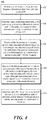
- FIG. 4 is a flowchart of an example method 400 for access point signal estimation.
- the method 400 may be performed by a computing device, such as a computing device described in FIG. 1 , e.g., in the form of an access point. Other computing devices may also be used to execute method 400.
- Method 400 may be implemented in the form of executable instructions stored on a machine-readable storage medium, such as the storage medium 130, and/or in the form of electronic circuitry.
- Transmission data may be, for example, a beacon packet sent by the particular access point using a 2.4 GHz radio.
- the transmission data may information regarding the particular access point, including - in some implementations - a transmit power.
- the transmission data e.g., the transmit power, may in some implementations be provided by the particular access point indirectly, e.g., from an access point management device in communication with the first access point and the particular access point.
- the first access point may also determine a signal strength measurement, e.g., an RSSI, for the beacon packet.
- a first pathloss value is determined that indicates a difference in transmit power of the particular access point and a received signal strength observed by the first access point (404). For example, in a situation where the transmit power of the particular access point is 15 dBm, and the RSSI observed by the first access point using the beacon packet was -65 dBm, the first pathloss in the 2.4 GHz frequency may be the difference between the two, e.g., 80 dB.
- a second pathloss value is received that is associated with the first frequency, the second pathloss value indicating a difference in transmit power of the particular access point and a received signal strength observed by a second access point in the first frequency (406).
- a second access point may, directly or indirectly using an access point management device, send a second pathloss value of 90 dB in the 2.4 GHz frequency.
- a third pathloss value is received that is associated with a second frequency that is different from the first frequency, the third pathloss value indicating a difference in transmit power of the particular access point and a received signal strength observed by the second access point in the second frequency (408).
- the second access point may, directly or indirectly using an access point management device, send a third pathloss value of 130 dB in the 5 GHz frequency.
- average pathloss values may be used. For example, the average pathloss over time may be more likely to provide a more consistent and/or predictable pathloss measurement.
- additional pathloss values from additional access points may be used to determine an estimated pathloss. For example, at the first access point, a fourth pathloss value may be received that is associated with the first frequency, the fourth pathloss value indicating a difference in transmit power of the particular access point and a received signal strength observed by a third access point in the first frequency, and a fifth pathloss value may be received that is associated with the second frequency, the fifth pathloss value indicating a difference in transmit power of the particular access point and a received signal strength observed by the third access point in the second frequency.
- the estimated pathloss may be adjusted using the fourth and fifth pathloss values. For example, a second estimated pathloss may be determined and averaged with the first determined pathloss estimate.
- signal estimation may be performed using a number of additional signal strength measurements from a number of other access points.
- An example of the present disclosure includes a method for access point signal estimation, implemented by a hardware processor, the method comprising: receiving, at a first access point and in a first frequency, transmission data from a particular access point; determining, based on the transmission data, a first pathloss value indicating a difference in transmit power of the particular access point and a received signal strength observed by the first access point; receiving, at the first access point, a second pathloss value associated with the first frequency, the second pathloss value indicating a difference in transmit power of the particular access point and a received signal strength observed by a second access point in the first frequency; receiving, at the first access point, a third pathloss value associated with a second frequency that is different from the first frequency, the third pathloss value indicating a difference in transmit power of the particular access point and a received signal strength observed by the second access point in the second frequency; and determining, using the first pathloss value, second pathloss value, and third pathloss value, an estimated pathloss between the first access point and
- a ratio of the first pathloss to the estimated pathloss is proportional to a ratio of the second pathloss to the third pathloss.
- the first pathloss value is determined using an average pathloss over a first period of time.
- the method comprises: receiving, at the first access point, a fourth pathloss value associated with the first frequency, the fourth pathloss value indicating a difference in transmit power of the particular access point and a received signal strength observed by a third access point in the first frequency; receiving, at the first access point, a fifth pathloss value associated with the second frequency, the fifth pathloss value indicating a difference in transmit power of the particular access point and a received signal strength observed by the third access point in the second frequency, and wherein the estimated pathloss is adjusted using the fourth pathloss value and fifth pathloss value.
- the estimated pathloss is adjusted by: generating a second estimated pathloss using the first pathloss value, fourth pathloss value, and fifth pathloss value; and averaging the estimated pathloss and the second estimated pathloss.
- the second pathloss value and third pathloss value are provided by a computing device that is separate from the particular access point, the first access point, and the second access point.
- examples provide a mechanism for determining an estimated signal strength for an access point using signal strength measurements of at least one other access point.
Landscapes
- Engineering & Computer Science (AREA)
- Computer Networks & Wireless Communication (AREA)
- Signal Processing (AREA)
- Quality & Reliability (AREA)
- Physics & Mathematics (AREA)
- Electromagnetism (AREA)
- Mobile Radio Communication Systems (AREA)
Applications Claiming Priority (1)
| Application Number | Priority Date | Filing Date | Title |
|---|---|---|---|
| US15/201,153 US10135552B2 (en) | 2016-07-01 | 2016-07-01 | Access point signal estimation |
Publications (2)
| Publication Number | Publication Date |
|---|---|
| EP3264643A1 true EP3264643A1 (de) | 2018-01-03 |
| EP3264643B1 EP3264643B1 (de) | 2019-03-20 |
Family
ID=59258087
Family Applications (1)
| Application Number | Title | Priority Date | Filing Date |
|---|---|---|---|
| EP17178729.4A Active EP3264643B1 (de) | 2016-07-01 | 2017-06-29 | Zugangspunktsignalschätzung |
Country Status (2)
| Country | Link |
|---|---|
| US (1) | US10135552B2 (de) |
| EP (1) | EP3264643B1 (de) |
Cited By (1)
| Publication number | Priority date | Publication date | Assignee | Title |
|---|---|---|---|---|
| EP3993289A1 (de) * | 2020-10-28 | 2022-05-04 | HERE Global B.V. | Verfahren und vorrichtung zur beschleunigung der schätzung eines funkmodells eines zugangspunkts |
Families Citing this family (2)
| Publication number | Priority date | Publication date | Assignee | Title |
|---|---|---|---|---|
| US10880898B2 (en) * | 2018-12-05 | 2020-12-29 | Verizon Patent And Licensing Inc. | Systems and methods for multi-band resource control |
| CN116938992A (zh) * | 2023-07-20 | 2023-10-24 | 维沃移动通信有限公司 | 通信控制电路、通信控制方法、装置、电子设备及介质 |
Citations (5)
| Publication number | Priority date | Publication date | Assignee | Title |
|---|---|---|---|---|
| WO2005069519A1 (en) * | 2004-01-08 | 2005-07-28 | Interdigital Technology Corporation | Wireless communication method and apparatus for optimizing the performance of access points |
| US7385945B1 (en) * | 2004-08-04 | 2008-06-10 | Cisco Technology, Inc. | Eliminating multicast/broadcast collisions in a wireless local area network |
| WO2010015286A1 (en) * | 2008-08-08 | 2010-02-11 | Nokia Siemens Networks Oy | Method and apparatus for controlling power of mobile station |
| US20130279349A1 (en) * | 2012-04-23 | 2013-10-24 | Santosh Pandey | Generating accurate dynamic heat maps |
| US20140314003A1 (en) * | 2013-04-19 | 2014-10-23 | Qualcomm Incorporated | Access point discovery channel |
Family Cites Families (5)
| Publication number | Priority date | Publication date | Assignee | Title |
|---|---|---|---|---|
| US20030087645A1 (en) * | 2001-11-08 | 2003-05-08 | Kim Byoung-Jo J. | Frequency assignment for multi-cell IEEE 802.11 wireless networks |
| AU2002348739A1 (en) * | 2002-12-19 | 2004-07-14 | Nokia Corporation | System and handover mechanism in frequency multiple band environment and equipment therefor |
| US7764653B2 (en) * | 2004-01-08 | 2010-07-27 | Interdigital Technology Corporation | Method and apparatus for autonomously determining the coverage area of an access point in a wireless communication system |
| US8238929B2 (en) * | 2009-12-03 | 2012-08-07 | Marvell World Trade Ltd. | RSSI estimation in multi-technology communication terminals |
| JP6261390B2 (ja) * | 2014-03-06 | 2018-01-17 | シャープ株式会社 | 携帯端末および携帯端末の制御方法 |
-
2016
- 2016-07-01 US US15/201,153 patent/US10135552B2/en active Active
-
2017
- 2017-06-29 EP EP17178729.4A patent/EP3264643B1/de active Active
Patent Citations (5)
| Publication number | Priority date | Publication date | Assignee | Title |
|---|---|---|---|---|
| WO2005069519A1 (en) * | 2004-01-08 | 2005-07-28 | Interdigital Technology Corporation | Wireless communication method and apparatus for optimizing the performance of access points |
| US7385945B1 (en) * | 2004-08-04 | 2008-06-10 | Cisco Technology, Inc. | Eliminating multicast/broadcast collisions in a wireless local area network |
| WO2010015286A1 (en) * | 2008-08-08 | 2010-02-11 | Nokia Siemens Networks Oy | Method and apparatus for controlling power of mobile station |
| US20130279349A1 (en) * | 2012-04-23 | 2013-10-24 | Santosh Pandey | Generating accurate dynamic heat maps |
| US20140314003A1 (en) * | 2013-04-19 | 2014-10-23 | Qualcomm Incorporated | Access point discovery channel |
Cited By (2)
| Publication number | Priority date | Publication date | Assignee | Title |
|---|---|---|---|---|
| EP3993289A1 (de) * | 2020-10-28 | 2022-05-04 | HERE Global B.V. | Verfahren und vorrichtung zur beschleunigung der schätzung eines funkmodells eines zugangspunkts |
| US11546779B2 (en) | 2020-10-28 | 2023-01-03 | Here Global B.V. | Method and apparatus for accelerating estimation of a radio model of an access point |
Also Published As
| Publication number | Publication date |
|---|---|
| US20180006742A1 (en) | 2018-01-04 |
| US10135552B2 (en) | 2018-11-20 |
| EP3264643B1 (de) | 2019-03-20 |
Similar Documents
| Publication | Publication Date | Title |
|---|---|---|
| US8699418B2 (en) | Band steering for multi-band wireless clients | |
| US10694451B2 (en) | Estimating a relative difference between signal strengths of wireless signals received by a device | |
| US10555184B2 (en) | Cell shaping in wireless communications networks | |
| CN104956237B (zh) | 距离估计方法、发送功率控制方法、用户装置、以及基站 | |
| US20120056786A1 (en) | Location estimation for wireless devices | |
| US9585124B2 (en) | Uplink-based wireless radio resource management | |
| EP3718360A1 (de) | Verbindungsstrahlmeldung für drahtlose netzwerke | |
| CA2901095C (en) | Mitigating interference with wireless communications | |
| US20100278117A1 (en) | Wireless channel switching using co-located radios | |
| US11889345B2 (en) | Event-based load balancing in 4G-5G multi-radio dual connectivity | |
| US20190386731A1 (en) | Scheduling method, base station, and terminal | |
| EP3264643B1 (de) | Zugangspunktsignalschätzung | |
| JP2020502862A (ja) | ビーム測定方法及び装置 | |
| US9923789B2 (en) | Determining access point power output | |
| US9655057B2 (en) | Noise floor driven access point transmission power | |
| KR20160136306A (ko) | 포지셔닝 측정 관리를 위한 방법 및 장치 | |
| US12156086B2 (en) | Device and method for prediction of metrics in a wireless network with multiple access points | |
| US9408181B2 (en) | Automatic calibration of probe request received signal strength indication (RSSI) threshold to control associations | |
| CN109392053B (zh) | 一种选择驻留小区的方法、设备及计算机可读存储介质 | |
| JP7310033B2 (ja) | 関数ベースのマッチングパターンを使用するフィンガープリンティングのための方法および装置 | |
| US10548090B2 (en) | Method and base station for determining an uplink power control target | |
| US10694431B2 (en) | User equipment and cell re-selection estimation method thereof | |
| EP2930991A1 (de) | Drahtlose kommunikationsvorrichtung und verfahren für verkehrsausgeglichene, kommunikation über zwei drahtlose netzwerke gleichzeitig | |
| WO2017177662A1 (zh) | 基站底噪值获取方法和装置 | |
| US10560978B2 (en) | Control plane connectivity for wireless devices |
Legal Events
| Date | Code | Title | Description |
|---|---|---|---|
| PUAI | Public reference made under article 153(3) epc to a published international application that has entered the european phase |
Free format text: ORIGINAL CODE: 0009012 |
|
| STAA | Information on the status of an ep patent application or granted ep patent |
Free format text: STATUS: THE APPLICATION HAS BEEN PUBLISHED |
|
| AK | Designated contracting states |
Kind code of ref document: A1 Designated state(s): AL AT BE BG CH CY CZ DE DK EE ES FI FR GB GR HR HU IE IS IT LI LT LU LV MC MK MT NL NO PL PT RO RS SE SI SK SM TR |
|
| AX | Request for extension of the european patent |
Extension state: BA ME |
|
| RAP1 | Party data changed (applicant data changed or rights of an application transferred) |
Owner name: ARUBA NETWORKS, INC. |
|
| STAA | Information on the status of an ep patent application or granted ep patent |
Free format text: STATUS: REQUEST FOR EXAMINATION WAS MADE |
|
| 17P | Request for examination filed |
Effective date: 20180703 |
|
| RBV | Designated contracting states (corrected) |
Designated state(s): AL AT BE BG CH CY CZ DE DK EE ES FI FR GB GR HR HU IE IS IT LI LT LU LV MC MK MT NL NO PL PT RO RS SE SI SK SM TR |
|
| GRAP | Despatch of communication of intention to grant a patent |
Free format text: ORIGINAL CODE: EPIDOSNIGR1 |
|
| STAA | Information on the status of an ep patent application or granted ep patent |
Free format text: STATUS: GRANT OF PATENT IS INTENDED |
|
| INTG | Intention to grant announced |
Effective date: 20180924 |
|
| GRAS | Grant fee paid |
Free format text: ORIGINAL CODE: EPIDOSNIGR3 |
|
| GRAA | (expected) grant |
Free format text: ORIGINAL CODE: 0009210 |
|
| STAA | Information on the status of an ep patent application or granted ep patent |
Free format text: STATUS: THE PATENT HAS BEEN GRANTED |
|
| RAP1 | Party data changed (applicant data changed or rights of an application transferred) |
Owner name: HEWLETT PACKARD ENTERPRISE DEVELOPMENT LP |
|
| AK | Designated contracting states |
Kind code of ref document: B1 Designated state(s): AL AT BE BG CH CY CZ DE DK EE ES FI FR GB GR HR HU IE IS IT LI LT LU LV MC MK MT NL NO PL PT RO RS SE SI SK SM TR |
|
| REG | Reference to a national code |
Ref country code: GB Ref legal event code: FG4D |
|
| REG | Reference to a national code |
Ref country code: CH Ref legal event code: EP |
|
| REG | Reference to a national code |
Ref country code: AT Ref legal event code: REF Ref document number: 1111589 Country of ref document: AT Kind code of ref document: T Effective date: 20190415 |
|
| REG | Reference to a national code |
Ref country code: IE Ref legal event code: FG4D |
|
| REG | Reference to a national code |
Ref country code: DE Ref legal event code: R096 Ref document number: 602017002793 Country of ref document: DE |
|
| REG | Reference to a national code |
Ref country code: NL Ref legal event code: MP Effective date: 20190320 |
|
| PG25 | Lapsed in a contracting state [announced via postgrant information from national office to epo] |
Ref country code: LT Free format text: LAPSE BECAUSE OF FAILURE TO SUBMIT A TRANSLATION OF THE DESCRIPTION OR TO PAY THE FEE WITHIN THE PRESCRIBED TIME-LIMIT Effective date: 20190320 Ref country code: NO Free format text: LAPSE BECAUSE OF FAILURE TO SUBMIT A TRANSLATION OF THE DESCRIPTION OR TO PAY THE FEE WITHIN THE PRESCRIBED TIME-LIMIT Effective date: 20190620 Ref country code: SE Free format text: LAPSE BECAUSE OF FAILURE TO SUBMIT A TRANSLATION OF THE DESCRIPTION OR TO PAY THE FEE WITHIN THE PRESCRIBED TIME-LIMIT Effective date: 20190320 Ref country code: FI Free format text: LAPSE BECAUSE OF FAILURE TO SUBMIT A TRANSLATION OF THE DESCRIPTION OR TO PAY THE FEE WITHIN THE PRESCRIBED TIME-LIMIT Effective date: 20190320 |
|
| REG | Reference to a national code |
Ref country code: LT Ref legal event code: MG4D |
|
| PG25 | Lapsed in a contracting state [announced via postgrant information from national office to epo] |
Ref country code: LV Free format text: LAPSE BECAUSE OF FAILURE TO SUBMIT A TRANSLATION OF THE DESCRIPTION OR TO PAY THE FEE WITHIN THE PRESCRIBED TIME-LIMIT Effective date: 20190320 Ref country code: RS Free format text: LAPSE BECAUSE OF FAILURE TO SUBMIT A TRANSLATION OF THE DESCRIPTION OR TO PAY THE FEE WITHIN THE PRESCRIBED TIME-LIMIT Effective date: 20190320 Ref country code: BG Free format text: LAPSE BECAUSE OF FAILURE TO SUBMIT A TRANSLATION OF THE DESCRIPTION OR TO PAY THE FEE WITHIN THE PRESCRIBED TIME-LIMIT Effective date: 20190620 Ref country code: GR Free format text: LAPSE BECAUSE OF FAILURE TO SUBMIT A TRANSLATION OF THE DESCRIPTION OR TO PAY THE FEE WITHIN THE PRESCRIBED TIME-LIMIT Effective date: 20190621 Ref country code: NL Free format text: LAPSE BECAUSE OF FAILURE TO SUBMIT A TRANSLATION OF THE DESCRIPTION OR TO PAY THE FEE WITHIN THE PRESCRIBED TIME-LIMIT Effective date: 20190320 Ref country code: HR Free format text: LAPSE BECAUSE OF FAILURE TO SUBMIT A TRANSLATION OF THE DESCRIPTION OR TO PAY THE FEE WITHIN THE PRESCRIBED TIME-LIMIT Effective date: 20190320 |
|
| REG | Reference to a national code |
Ref country code: AT Ref legal event code: MK05 Ref document number: 1111589 Country of ref document: AT Kind code of ref document: T Effective date: 20190320 |
|
| PG25 | Lapsed in a contracting state [announced via postgrant information from national office to epo] |
Ref country code: ES Free format text: LAPSE BECAUSE OF FAILURE TO SUBMIT A TRANSLATION OF THE DESCRIPTION OR TO PAY THE FEE WITHIN THE PRESCRIBED TIME-LIMIT Effective date: 20190320 Ref country code: AL Free format text: LAPSE BECAUSE OF FAILURE TO SUBMIT A TRANSLATION OF THE DESCRIPTION OR TO PAY THE FEE WITHIN THE PRESCRIBED TIME-LIMIT Effective date: 20190320 Ref country code: PT Free format text: LAPSE BECAUSE OF FAILURE TO SUBMIT A TRANSLATION OF THE DESCRIPTION OR TO PAY THE FEE WITHIN THE PRESCRIBED TIME-LIMIT Effective date: 20190720 Ref country code: SK Free format text: LAPSE BECAUSE OF FAILURE TO SUBMIT A TRANSLATION OF THE DESCRIPTION OR TO PAY THE FEE WITHIN THE PRESCRIBED TIME-LIMIT Effective date: 20190320 Ref country code: IT Free format text: LAPSE BECAUSE OF FAILURE TO SUBMIT A TRANSLATION OF THE DESCRIPTION OR TO PAY THE FEE WITHIN THE PRESCRIBED TIME-LIMIT Effective date: 20190320 Ref country code: EE Free format text: LAPSE BECAUSE OF FAILURE TO SUBMIT A TRANSLATION OF THE DESCRIPTION OR TO PAY THE FEE WITHIN THE PRESCRIBED TIME-LIMIT Effective date: 20190320 Ref country code: CZ Free format text: LAPSE BECAUSE OF FAILURE TO SUBMIT A TRANSLATION OF THE DESCRIPTION OR TO PAY THE FEE WITHIN THE PRESCRIBED TIME-LIMIT Effective date: 20190320 Ref country code: RO Free format text: LAPSE BECAUSE OF FAILURE TO SUBMIT A TRANSLATION OF THE DESCRIPTION OR TO PAY THE FEE WITHIN THE PRESCRIBED TIME-LIMIT Effective date: 20190320 |
|
| PG25 | Lapsed in a contracting state [announced via postgrant information from national office to epo] |
Ref country code: SM Free format text: LAPSE BECAUSE OF FAILURE TO SUBMIT A TRANSLATION OF THE DESCRIPTION OR TO PAY THE FEE WITHIN THE PRESCRIBED TIME-LIMIT Effective date: 20190320 Ref country code: PL Free format text: LAPSE BECAUSE OF FAILURE TO SUBMIT A TRANSLATION OF THE DESCRIPTION OR TO PAY THE FEE WITHIN THE PRESCRIBED TIME-LIMIT Effective date: 20190320 |
|
| PG25 | Lapsed in a contracting state [announced via postgrant information from national office to epo] |
Ref country code: IS Free format text: LAPSE BECAUSE OF FAILURE TO SUBMIT A TRANSLATION OF THE DESCRIPTION OR TO PAY THE FEE WITHIN THE PRESCRIBED TIME-LIMIT Effective date: 20190720 Ref country code: AT Free format text: LAPSE BECAUSE OF FAILURE TO SUBMIT A TRANSLATION OF THE DESCRIPTION OR TO PAY THE FEE WITHIN THE PRESCRIBED TIME-LIMIT Effective date: 20190320 |
|
| REG | Reference to a national code |
Ref country code: DE Ref legal event code: R097 Ref document number: 602017002793 Country of ref document: DE |
|
| PLBE | No opposition filed within time limit |
Free format text: ORIGINAL CODE: 0009261 |
|
| STAA | Information on the status of an ep patent application or granted ep patent |
Free format text: STATUS: NO OPPOSITION FILED WITHIN TIME LIMIT |
|
| PG25 | Lapsed in a contracting state [announced via postgrant information from national office to epo] |
Ref country code: MC Free format text: LAPSE BECAUSE OF FAILURE TO SUBMIT A TRANSLATION OF THE DESCRIPTION OR TO PAY THE FEE WITHIN THE PRESCRIBED TIME-LIMIT Effective date: 20190320 Ref country code: DK Free format text: LAPSE BECAUSE OF FAILURE TO SUBMIT A TRANSLATION OF THE DESCRIPTION OR TO PAY THE FEE WITHIN THE PRESCRIBED TIME-LIMIT Effective date: 20190320 |
|
| 26N | No opposition filed |
Effective date: 20200102 |
|
| PG25 | Lapsed in a contracting state [announced via postgrant information from national office to epo] |
Ref country code: SI Free format text: LAPSE BECAUSE OF FAILURE TO SUBMIT A TRANSLATION OF THE DESCRIPTION OR TO PAY THE FEE WITHIN THE PRESCRIBED TIME-LIMIT Effective date: 20190320 |
|
| REG | Reference to a national code |
Ref country code: BE Ref legal event code: MM Effective date: 20190630 |
|
| PG25 | Lapsed in a contracting state [announced via postgrant information from national office to epo] |
Ref country code: TR Free format text: LAPSE BECAUSE OF FAILURE TO SUBMIT A TRANSLATION OF THE DESCRIPTION OR TO PAY THE FEE WITHIN THE PRESCRIBED TIME-LIMIT Effective date: 20190320 |
|
| PG25 | Lapsed in a contracting state [announced via postgrant information from national office to epo] |
Ref country code: IE Free format text: LAPSE BECAUSE OF NON-PAYMENT OF DUE FEES Effective date: 20190629 |
|
| PG25 | Lapsed in a contracting state [announced via postgrant information from national office to epo] |
Ref country code: LU Free format text: LAPSE BECAUSE OF NON-PAYMENT OF DUE FEES Effective date: 20190629 Ref country code: BE Free format text: LAPSE BECAUSE OF NON-PAYMENT OF DUE FEES Effective date: 20190630 |
|
| PG25 | Lapsed in a contracting state [announced via postgrant information from national office to epo] |
Ref country code: FR Free format text: LAPSE BECAUSE OF NON-PAYMENT OF DUE FEES Effective date: 20190630 |
|
| REG | Reference to a national code |
Ref country code: CH Ref legal event code: PL |
|
| PG25 | Lapsed in a contracting state [announced via postgrant information from national office to epo] |
Ref country code: CH Free format text: LAPSE BECAUSE OF NON-PAYMENT OF DUE FEES Effective date: 20200630 Ref country code: LI Free format text: LAPSE BECAUSE OF NON-PAYMENT OF DUE FEES Effective date: 20200630 |
|
| PG25 | Lapsed in a contracting state [announced via postgrant information from national office to epo] |
Ref country code: CY Free format text: LAPSE BECAUSE OF FAILURE TO SUBMIT A TRANSLATION OF THE DESCRIPTION OR TO PAY THE FEE WITHIN THE PRESCRIBED TIME-LIMIT Effective date: 20190320 |
|
| PG25 | Lapsed in a contracting state [announced via postgrant information from national office to epo] |
Ref country code: HU Free format text: LAPSE BECAUSE OF FAILURE TO SUBMIT A TRANSLATION OF THE DESCRIPTION OR TO PAY THE FEE WITHIN THE PRESCRIBED TIME-LIMIT; INVALID AB INITIO Effective date: 20170629 Ref country code: MT Free format text: LAPSE BECAUSE OF FAILURE TO SUBMIT A TRANSLATION OF THE DESCRIPTION OR TO PAY THE FEE WITHIN THE PRESCRIBED TIME-LIMIT Effective date: 20190320 |
|
| PG25 | Lapsed in a contracting state [announced via postgrant information from national office to epo] |
Ref country code: MK Free format text: LAPSE BECAUSE OF FAILURE TO SUBMIT A TRANSLATION OF THE DESCRIPTION OR TO PAY THE FEE WITHIN THE PRESCRIBED TIME-LIMIT Effective date: 20190320 |
|
| REG | Reference to a national code |
Ref country code: DE Ref legal event code: R082 Ref document number: 602017002793 Country of ref document: DE Representative=s name: PROCK, THOMAS, DR., GB |
|
| REG | Reference to a national code |
Ref country code: DE Ref legal event code: R081 Ref document number: 602017002793 Country of ref document: DE Owner name: HEWLETT PACKARD ENTERPRISE DEVELOPMENT LP, SPR, US Free format text: FORMER OWNER: HEWLETT PACKARD ENTERPRISE DEVELOPMENT LP, HOUSTON, TEX., US |
|
| PGFP | Annual fee paid to national office [announced via postgrant information from national office to epo] |
Ref country code: DE Payment date: 20250626 Year of fee payment: 9 |
|
| PGFP | Annual fee paid to national office [announced via postgrant information from national office to epo] |
Ref country code: GB Payment date: 20250617 Year of fee payment: 9 |