EP3264556A1 - Electric power converting device, electric power management system, and electric power converting method - Google Patents
Electric power converting device, electric power management system, and electric power converting method Download PDFInfo
- Publication number
- EP3264556A1 EP3264556A1 EP16755604.2A EP16755604A EP3264556A1 EP 3264556 A1 EP3264556 A1 EP 3264556A1 EP 16755604 A EP16755604 A EP 16755604A EP 3264556 A1 EP3264556 A1 EP 3264556A1
- Authority
- EP
- European Patent Office
- Prior art keywords
- power
- output
- suppression
- power source
- distributed
- Prior art date
- Legal status (The legal status is an assumption and is not a legal conclusion. Google has not performed a legal analysis and makes no representation as to the accuracy of the status listed.)
- Withdrawn
Links
Images




Classifications
-
- H—ELECTRICITY
- H02—GENERATION; CONVERSION OR DISTRIBUTION OF ELECTRIC POWER
- H02J—ELECTRIC POWER NETWORKS; CIRCUIT ARRANGEMENTS OR SYSTEMS FOR SUPPLYING OR DISTRIBUTING ELECTRIC POWER; SYSTEMS FOR STORING ELECTRIC ENERGY
- H02J3/00—Circuit arrangements for AC mains or AC distribution networks
- H02J3/003—Load forecast, e.g. methods or systems for forecasting future load demand
-
- G—PHYSICS
- G05—CONTROLLING; REGULATING
- G05F—SYSTEMS FOR REGULATING ELECTRIC OR MAGNETIC VARIABLES
- G05F1/00—Automatic systems in which deviations of an electric quantity from one or more predetermined values are detected at the output of the system and fed back to a device within the system to restore the detected quantity to its predetermined value or values, i.e. retroactive systems
- G05F1/66—Regulating electric power
- G05F1/67—Regulating electric power to the maximum power available from a generator, e.g. from solar cell
-
- H—ELECTRICITY
- H02—GENERATION; CONVERSION OR DISTRIBUTION OF ELECTRIC POWER
- H02J—ELECTRIC POWER NETWORKS; CIRCUIT ARRANGEMENTS OR SYSTEMS FOR SUPPLYING OR DISTRIBUTING ELECTRIC POWER; SYSTEMS FOR STORING ELECTRIC ENERGY
- H02J3/00—Circuit arrangements for AC mains or AC distribution networks
- H02J3/28—Arrangements for balancing of the load in networks by storage of energy
- H02J3/32—Arrangements for balancing of the load in networks by storage of energy using batteries or super capacitors with converting means
-
- H—ELECTRICITY
- H02—GENERATION; CONVERSION OR DISTRIBUTION OF ELECTRIC POWER
- H02J—ELECTRIC POWER NETWORKS; CIRCUIT ARRANGEMENTS OR SYSTEMS FOR SUPPLYING OR DISTRIBUTING ELECTRIC POWER; SYSTEMS FOR STORING ELECTRIC ENERGY
- H02J3/00—Circuit arrangements for AC mains or AC distribution networks
- H02J3/38—Arrangements for feeding a single network from two or more generators or sources in parallel; Arrangements for feeding already energised networks from additional generators or sources in parallel
-
- H—ELECTRICITY
- H02—GENERATION; CONVERSION OR DISTRIBUTION OF ELECTRIC POWER
- H02J—ELECTRIC POWER NETWORKS; CIRCUIT ARRANGEMENTS OR SYSTEMS FOR SUPPLYING OR DISTRIBUTING ELECTRIC POWER; SYSTEMS FOR STORING ELECTRIC ENERGY
- H02J3/00—Circuit arrangements for AC mains or AC distribution networks
- H02J3/38—Arrangements for feeding a single network from two or more generators or sources in parallel; Arrangements for feeding already energised networks from additional generators or sources in parallel
- H02J3/381—Dispersed generators
-
- H—ELECTRICITY
- H02—GENERATION; CONVERSION OR DISTRIBUTION OF ELECTRIC POWER
- H02J—ELECTRIC POWER NETWORKS; CIRCUIT ARRANGEMENTS OR SYSTEMS FOR SUPPLYING OR DISTRIBUTING ELECTRIC POWER; SYSTEMS FOR STORING ELECTRIC ENERGY
- H02J3/00—Circuit arrangements for AC mains or AC distribution networks
- H02J3/38—Arrangements for feeding a single network from two or more generators or sources in parallel; Arrangements for feeding already energised networks from additional generators or sources in parallel
- H02J3/46—Controlling the sharing of generated power between the generators, sources or networks
- H02J3/466—Scheduling or selectively controlling the operation of the generators or sources, e.g. connecting or disconnecting generators to meet a demand
-
- H—ELECTRICITY
- H02—GENERATION; CONVERSION OR DISTRIBUTION OF ELECTRIC POWER
- H02J—ELECTRIC POWER NETWORKS; CIRCUIT ARRANGEMENTS OR SYSTEMS FOR SUPPLYING OR DISTRIBUTING ELECTRIC POWER; SYSTEMS FOR STORING ELECTRIC ENERGY
- H02J7/00—Circuit arrangements for charging or discharging batteries or for supplying loads from batteries
- H02J7/34—Parallel operation in networks using both storage and other DC sources, e.g. providing buffering
- H02J7/35—Parallel operation in networks using both storage and other DC sources, e.g. providing buffering with light sensitive cells
-
- H—ELECTRICITY
- H02—GENERATION; CONVERSION OR DISTRIBUTION OF ELECTRIC POWER
- H02J—ELECTRIC POWER NETWORKS; CIRCUIT ARRANGEMENTS OR SYSTEMS FOR SUPPLYING OR DISTRIBUTING ELECTRIC POWER; SYSTEMS FOR STORING ELECTRIC ENERGY
- H02J7/00—Circuit arrangements for charging or discharging batteries or for supplying loads from batteries
- H02J7/90—Regulation of charging or discharging current or voltage
- H02J7/92—Regulation of charging or discharging current or voltage with prioritisation of loads or sources
-
- H—ELECTRICITY
- H02—GENERATION; CONVERSION OR DISTRIBUTION OF ELECTRIC POWER
- H02M—APPARATUS FOR CONVERSION BETWEEN AC AND AC, BETWEEN AC AND DC, OR BETWEEN DC AND DC, AND FOR USE WITH MAINS OR SIMILAR POWER SUPPLY SYSTEMS; CONVERSION OF DC OR AC INPUT POWER INTO SURGE OUTPUT POWER; CONTROL OR REGULATION THEREOF
- H02M11/00—Power conversion systems not covered by the preceding groups
-
- H—ELECTRICITY
- H02—GENERATION; CONVERSION OR DISTRIBUTION OF ELECTRIC POWER
- H02M—APPARATUS FOR CONVERSION BETWEEN AC AND AC, BETWEEN AC AND DC, OR BETWEEN DC AND DC, AND FOR USE WITH MAINS OR SIMILAR POWER SUPPLY SYSTEMS; CONVERSION OF DC OR AC INPUT POWER INTO SURGE OUTPUT POWER; CONTROL OR REGULATION THEREOF
- H02M7/00—Conversion of AC power input into DC power output; Conversion of DC power input into AC power output
- H02M7/42—Conversion of DC power input into AC power output without possibility of reversal
- H02M7/44—Conversion of DC power input into AC power output without possibility of reversal by static converters
- H02M7/48—Conversion of DC power input into AC power output without possibility of reversal by static converters using discharge tubes with control electrode or semiconductor devices with control electrode
-
- F—MECHANICAL ENGINEERING; LIGHTING; HEATING; WEAPONS; BLASTING
- F03—MACHINES OR ENGINES FOR LIQUIDS; WIND, SPRING, OR WEIGHT MOTORS; PRODUCING MECHANICAL POWER OR A REACTIVE PROPULSIVE THRUST, NOT OTHERWISE PROVIDED FOR
- F03D—WIND MOTORS
- F03D7/00—Controlling wind motors
- F03D7/02—Controlling wind motors the wind motors having rotation axis substantially parallel to the air flow entering the rotor
- F03D7/028—Controlling wind motors the wind motors having rotation axis substantially parallel to the air flow entering the rotor controlling wind motor output power
- F03D7/0284—Controlling wind motors the wind motors having rotation axis substantially parallel to the air flow entering the rotor controlling wind motor output power in relation to the state of the electric grid
-
- H—ELECTRICITY
- H02—GENERATION; CONVERSION OR DISTRIBUTION OF ELECTRIC POWER
- H02J—ELECTRIC POWER NETWORKS; CIRCUIT ARRANGEMENTS OR SYSTEMS FOR SUPPLYING OR DISTRIBUTING ELECTRIC POWER; SYSTEMS FOR STORING ELECTRIC ENERGY
- H02J2101/00—Supply or distribution of decentralised, dispersed or local electric power generation
- H02J2101/20—Dispersed power generation using renewable energy sources
- H02J2101/22—Solar energy
- H02J2101/24—Photovoltaics
-
- H—ELECTRICITY
- H02—GENERATION; CONVERSION OR DISTRIBUTION OF ELECTRIC POWER
- H02J—ELECTRIC POWER NETWORKS; CIRCUIT ARRANGEMENTS OR SYSTEMS FOR SUPPLYING OR DISTRIBUTING ELECTRIC POWER; SYSTEMS FOR STORING ELECTRIC ENERGY
- H02J2207/00—Details of circuit arrangements for charging or discharging batteries or supplying loads from batteries
- H02J2207/20—Charging or discharging characterised by the power electronics converter
-
- H—ELECTRICITY
- H02—GENERATION; CONVERSION OR DISTRIBUTION OF ELECTRIC POWER
- H02J—ELECTRIC POWER NETWORKS; CIRCUIT ARRANGEMENTS OR SYSTEMS FOR SUPPLYING OR DISTRIBUTING ELECTRIC POWER; SYSTEMS FOR STORING ELECTRIC ENERGY
- H02J3/00—Circuit arrangements for AC mains or AC distribution networks
- H02J3/38—Arrangements for feeding a single network from two or more generators or sources in parallel; Arrangements for feeding already energised networks from additional generators or sources in parallel
- H02J3/388—Arrangements for the handling of islanding, e.g. for disconnection or for avoiding the disconnection of power
-
- H—ELECTRICITY
- H02—GENERATION; CONVERSION OR DISTRIBUTION OF ELECTRIC POWER
- H02M—APPARATUS FOR CONVERSION BETWEEN AC AND AC, BETWEEN AC AND DC, OR BETWEEN DC AND DC, AND FOR USE WITH MAINS OR SIMILAR POWER SUPPLY SYSTEMS; CONVERSION OF DC OR AC INPUT POWER INTO SURGE OUTPUT POWER; CONTROL OR REGULATION THEREOF
- H02M1/00—Details of apparatus for conversion
- H02M1/0003—Details of control, feedback or regulation circuits
- H02M1/0016—Control circuits providing compensation of output voltage deviations using feedforward of disturbance parameters
-
- Y—GENERAL TAGGING OF NEW TECHNOLOGICAL DEVELOPMENTS; GENERAL TAGGING OF CROSS-SECTIONAL TECHNOLOGIES SPANNING OVER SEVERAL SECTIONS OF THE IPC; TECHNICAL SUBJECTS COVERED BY FORMER USPC CROSS-REFERENCE ART COLLECTIONS [XRACs] AND DIGESTS
- Y02—TECHNOLOGIES OR APPLICATIONS FOR MITIGATION OR ADAPTATION AGAINST CLIMATE CHANGE
- Y02E—REDUCTION OF GREENHOUSE GAS [GHG] EMISSIONS, RELATED TO ENERGY GENERATION, TRANSMISSION OR DISTRIBUTION
- Y02E10/00—Energy generation through renewable energy sources
- Y02E10/50—Photovoltaic [PV] energy
- Y02E10/56—Power conversion systems, e.g. maximum power point trackers
-
- Y—GENERAL TAGGING OF NEW TECHNOLOGICAL DEVELOPMENTS; GENERAL TAGGING OF CROSS-SECTIONAL TECHNOLOGIES SPANNING OVER SEVERAL SECTIONS OF THE IPC; TECHNICAL SUBJECTS COVERED BY FORMER USPC CROSS-REFERENCE ART COLLECTIONS [XRACs] AND DIGESTS
- Y02—TECHNOLOGIES OR APPLICATIONS FOR MITIGATION OR ADAPTATION AGAINST CLIMATE CHANGE
- Y02E—REDUCTION OF GREENHOUSE GAS [GHG] EMISSIONS, RELATED TO ENERGY GENERATION, TRANSMISSION OR DISTRIBUTION
- Y02E10/00—Energy generation through renewable energy sources
- Y02E10/70—Wind energy
- Y02E10/76—Power conversion electric or electronic aspects
-
- Y—GENERAL TAGGING OF NEW TECHNOLOGICAL DEVELOPMENTS; GENERAL TAGGING OF CROSS-SECTIONAL TECHNOLOGIES SPANNING OVER SEVERAL SECTIONS OF THE IPC; TECHNICAL SUBJECTS COVERED BY FORMER USPC CROSS-REFERENCE ART COLLECTIONS [XRACs] AND DIGESTS
- Y02—TECHNOLOGIES OR APPLICATIONS FOR MITIGATION OR ADAPTATION AGAINST CLIMATE CHANGE
- Y02E—REDUCTION OF GREENHOUSE GAS [GHG] EMISSIONS, RELATED TO ENERGY GENERATION, TRANSMISSION OR DISTRIBUTION
- Y02E70/00—Other energy conversion or management systems reducing GHG emissions
- Y02E70/30—Systems combining energy storage with energy generation of non-fossil origin
-
- Y—GENERAL TAGGING OF NEW TECHNOLOGICAL DEVELOPMENTS; GENERAL TAGGING OF CROSS-SECTIONAL TECHNOLOGIES SPANNING OVER SEVERAL SECTIONS OF THE IPC; TECHNICAL SUBJECTS COVERED BY FORMER USPC CROSS-REFERENCE ART COLLECTIONS [XRACs] AND DIGESTS
- Y04—INFORMATION OR COMMUNICATION TECHNOLOGIES HAVING AN IMPACT ON OTHER TECHNOLOGY AREAS
- Y04S—SYSTEMS INTEGRATING TECHNOLOGIES RELATED TO POWER NETWORK OPERATION, COMMUNICATION OR INFORMATION TECHNOLOGIES FOR IMPROVING THE ELECTRICAL POWER GENERATION, TRANSMISSION, DISTRIBUTION, MANAGEMENT OR USAGE, i.e. SMART GRIDS
- Y04S10/00—Systems supporting electrical power generation, transmission or distribution
- Y04S10/50—Systems or methods supporting the power network operation or management, involving a certain degree of interaction with the load-side end user applications
Definitions
- the present invention relates to a power converting apparatus that converts a DC power to an AC power, a power management system including the power converting apparatus, and a power converting method.
- a power converting apparatus connected to a distributed power source that outputs a DC power is known.
- the power converting apparatus includes a DC convertor (DC/DC convertor) that converts a voltage of a DC power input from the distributed power source; and an inverter that converts the DC power input from the DC convertor to an AC power (for example, Patent Document 1).
- output suppression message a message instructing suppression of output of the distributed power source
- the power converting apparatus needs to suppress the output of the distributed power source to equal to or less than a suppression power threshold defined by the output suppression message.
- Patent Document 1 Japanese Application Publication No. 2014-171359
- a power converting apparatus comprises an inverter that converts a DC (Direct Current) power input from a distributed power source to an AC (Alternating Current) power; and a controller that suppresses an output of the distributed power source to equal to or lower than a suppression power threshold indicating a suppression degree for the output of the distributed power source.
- the controller performs a control of increasing the output of the distributed power source to exceed the suppression power threshold, when there is a period, where the output of the distributed power source falls below the suppression power threshold, in an accumulation period included in a suppression period in which the output of the distributed power source is suppressed.
- a power management system comprises a power converting apparatus that converts a DC power input from a distributed power source to an AC power; and a controller that suppresses an output of the distributed power source equal to or lower than a suppression power threshold indicating a suppression degree for the output of the distributed power source.
- the controller performs a control of increasing the output of the distributed power source to exceed the suppression power threshold, when there is a period, where the output of the distributed power source falls below the suppression power threshold, in an accumulation period included in a suspension period for suppressing the output of the distributed power source.
- a power converting apparatus comprises an inverter that converts a DC power input from a distributed power source to an AC power, converts a DC power input from a storage battery to an AC power, and converts a AC power to a DC power output to the storage battery; and a controller that suppresses an output of the distributed power source equal to or lower than a suppression power threshold indicating a suppression degree for the output of the distributed power source.
- the controller performs a control of increasing the output of the distributed power source to exceed the suppression power threshold, in an accumulation period included in a suppression period in which the output of the distributed power source is suppressed, when the storage battery is charged with the output of the distributed power source.
- a power management system comprises a power converting apparatus that converts a DC power input from a distributed power source to an AC power, converts a DC power input from a storage battery to an AC power, and converts a AC power to a DC power output to the storage battery; and a controller that suppresses an output of the distributed power source equal to or lower than a suppression power threshold indicating a suppression degree for the output of the distributed power source.
- the controller performs a control of increasing the output of the distributed power source to exceed the suppression power threshold, in an accumulation period included in a suppression period in which the output of the distributed power source is suppressed, when the storage battery is charged with the output of the distributed power source.
- a power converting method comprising the steps of: converting a DC power input from a distributed power source to an AC power, converting a DC power input from a storage battery to an AC power, and converting a AC power to a DC power output to the storage battery; suppressing an output of the distributed power source to equal to or lower than a suppression power threshold indicating a suppression degree for the output of the distributed power source; and performing a control of increasing the output of the distributed power source so that the output of the distributed power source exceeds the suppression power threshold, in an accumulation period included in a suppression period in which the output of the distributed power source is suppressed, when the storage battery is charged with the output of the distributed power source.
- the output of the distributed power source may be inevitably smaller than the suppression power threshold due to a predetermined factor.
- the predetermined factor may include an insufficient solar radiation.
- the distributed power source is a wind energy conversion system, the predetermined factor may include an insufficient amount of winds. Such a situation is greatly disadvantageous to a user.
- a power converting apparatus comprises an inverter that converts a DC (Direct Current) power input from a distributed power source to an AC (Alternating Current) power; and a controller that suppresses an output of the distributed power source to equal to or lower than a suppression power threshold indicating a suppression degree for the output of the distributed power source.
- the controller performs a control of increasing the output of the distributed power source to exceed the suppression power threshold, when there is a period, where the output of the distributed power source falls below the suppression power threshold, in an accumulation period included in a suppression period in which the output of the distributed power source is suppressed.
- the controller performs a control of increasing the output of the distributed power source to exceed the suppression power threshold, when there is, in an accumulation period, a period where the output of the distributed power source falls below the suppression power threshold value. Therefore, even when there occurs a situation where the output of the distributed power source is inevitably smaller than the suppression power threshold value due to a predetermined factor such as an insufficient solar radiation, the output of the distributed power source may be increased to exceed the suppression power threshold value to alleviate a disadvantage of a user.
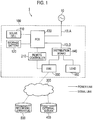
- Fig. 1 is a diagram illustrating the power management system 1 according to the embodiment.
- the power management system 1 includes a consumer's facility 100, an external server 400, and a recording apparatus 500.
- the consumer's facility 100 has an EMS 200, and the EMS 200 communicates with the external server 400 and the recording apparatus 500 via a network 300.
- the consumer's facility 100 includes a solar cell 110, a storage battery 120, a PCS 130, a distribution board 140, and a load 150. Furthermore, the consumer's facility 100 includes the EMS 200 and a remote controller 210.
- the solar cell 110 is an equipment that generates power in response to reception of solar light.
- the solar cell 110 outputs the generated DC power.
- An amount of power to be generated by the solar cell 110 varies depending on an amount of the solar radiation entering the solar cell 110.
- the solar cell 110 is an example of a distributed power source to operate in accordance with an output suppression message described later.
- the storage battery 120 is an equipment in which power is accumulated.
- the storage battery 120 outputs the accumulated DC power. It should be noted that in the embodiment, the storage battery 120 needs not to operate in accordance with the output suppression message described later.
- the PCS 130 (PCS: Power Conditioning System) is an example of a power converting apparatus that converts a DC power to an AC power.
- the PCS 130 is connected to a main power line 10L (herein, a main power line 10LA and a main power line 10LB) connected to a power grid 10, and connected to both the solar cell 110 and the storage battery 120.
- the main power line 10LA is a power line connecting the power grid 10 and the PCS 130
- the main power line 10LB is a power line connecting the PCS 130 and the distribution board 140.
- the PCS 130 converts the DC power input from the solar cell 110 to an AC power, and converts the DC power input from the storage battery 120 to an AC power. Furthermore, the PCS 130 converts an AC power supplied from the power grid 10 to a DC power.
- the distribution board 140 is connected to the main power line 10L (herein, the main power line 10LB).
- the distribution board 140 divides the main power line 10LB into a plurality of power lines, and distributes the power to an equipment (herein, the load 150 and the EMS 200) connected to the plurality of power lines.
- the load 150 is an equipment in which the power supplied via the power line is consumed.
- Examples of the load 150 include an equipment such as a refrigerator, a lighting, an air conditioner, and a TV.
- the load 150 may be a single equipment, and may include a plurality of equipments.
- the EMS 200 is an equipment (EMS: Energy Management System) that manages power information indicating the power supplied to the consumer's facility 100 from the power grid 10.
- the EMS 200 may manage an amount of power to be generated by the solar cell 110, an amount of power to be stored in the storage battery 120, and an amount of power to be discharged from the storage battery 120.
- the EMS 200 is connected to the remote controller 210 and the network 300.
- the EMS 200 receives the power suppression message described later from the external server 400, and notifies the remote controller 210 of the power suppression message.
- the EMS 200 receives a schedule (calendar) described later from the external server 400, and based on the schedule (calendar), notifies the remote controller 210 of the power suppression message.
- the PCS 130 has the remote controller 210 provided in connection with the PCS 130, and the remote controller 210 notifies the PCS 130 of various types of messages to operate the PCS 130.
- the remote controller 210 notifies the PCS 130 of the power suppression message received from the EMS 200.
- the network 300 is a communication network by which the EMS 200, the external server 400, and the recording apparatus 500 are connected.
- the network 300 may be the Internet.
- the network 300 may include a mobile communication network.
- the external server 400 notifies the output suppression message that is a message to instruct suppression of the output of the distributed power source (herein, the solar cell 110).
- the external server 400 may manage a schedule (calendar), as a whole of the power grid 10, including a date and time for suppressing the output of the distributed power source.
- the external server 400 notifies the output suppression message, based on such a schedule (calendar).
- the external server 400 may notify the EMS 200 of such a schedule (calendar).
- the output suppression message and the schedule include information indicating a suppression degree (an output suppression power threshold, for example) for the output of the distributed power source (herein, the solar cell 110).
- the suppression degree may be represented by an absolute value (xx kW, for example) of the output of the distributed power source (herein, the solar cell 110).
- the suppression degree may be represented by a relative value (decrease by xx kW, for example) of the output of the distributed power source (herein, the solar cell 110).
- the suppression degree may be represented by a suppression rate (xx%, for example) of the output of the distributed power source (herein, the solar cell 110).
- the suppression rate preferably is a rate of the distributed power source relative to the output certified, as an output capability of the PCS that controls the distributed power source (hereinafter, facility certified output), when the distributed power source is installed in the consumer's facility 100. If the output capability of the distributed power source and that of the PCS differ, either one of a smaller output capability is selected, as the facility certified output. When a plurality of PCSs are installed, the facility certified output is a sum of the output capabilities of the plurality of PCSs.
- the recording apparatus 500 is an equipment that records various types of information. Specifically, the recording apparatus 500 records a verification record to verify whether or not the suppression of the output of the distributed power source is correctly executed according to the output suppression message.
- the verification record is an accumulated value of outputs of the distributed power source in an accumulation period (30 minutes, for example) included in the suppression period in which the output of the distributed power source is suppressed by the output suppression message. In such a case, in the verification record accumulated for each accumulation period, the suppression of the output of the distributed power source may be correctly executed.
- Fig. 2 is a diagram illustrating the PCS 130 according to the embodiment.
- the PCS 130 is connected to a power line 11L connected to the main power line 10LA, and a power line 12L connected to the main power line 10LB. Furthermore, a power line 13L connecting the power line 11L and the power line 12L is provided. The power line 13L is connected closer to the power line 11L at the main power line 10LA side than a switch 11SW, and connected closer to the power line 12L at the main power line 10LB than a switch 12SW.
- the power line 11L is a power line connecting the power grid 10 and an inverter 133.
- the power line 11L may be a power line configuring a part of the main power line 10LA, and may be a power line divided from the main power line 10LA.
- the power line 12L is a power line connecting the inverter 133 and the distribution board 140 (load 150).
- the power line 12L may be a power line configuring a part of the main power line 10LB, and may be a power line divided from the main power line 10LB.
- the PCS 130 includes the switch 11SW provided on the power line 11L, the switch 12SW provided on the power line 12L, and a switch 13SW provided on the power line 13L.
- the switch 11SW is controlled to be in a closed state in a grid connected state in which the PCS 130 is connected to the power grid 10. On the other hand, the switch 11SW is controlled to be in an opened state in a self-sustained state in which the PCS 130 parallels off the power grid 10.
- the switch 12SW is controlled to be in an opened state in a grid connected state in which the PCS 130 is connected to the power grid 10.
- the switch 11SW is controlled to be in a closed state in a self-sustained state in which the PCS 130 is disconnected from the power grid 10.
- the switch 13SW is controlled to be in a closed state in a grid connected state in which the distribution board 140 (load 150) is connected to the power grid 10. Likewise, the switch 13SW is controlled to be in a closed state in a grid connected state in which the PCS 130 is connected to the power grid 10. On the other hand, the switch 13SW is controlled to be in an opened state in a self-sustained state in which the distribution board 140 (load 150) is disconnected from the power grid 10. Likewise, the switch 13SW is controlled to be in an opened state in a self-sustained state in which the PCS 130 is disconnected from the power grid 10.
- both the PCS 130 and the distribution board 140 (load 150) are connected to the power grid 10. Therefore, in such a grid connected state, the switch 11SW and the switch 13SW are controlled to be in a closed state, and the switch 12SW is controlled to be in an opened state.
- the switch 11SW and the switch 13SW are controlled to be in an opened state, and the switch 12SW is controlled to be in a closed state.
- the PCS 130 includes a DC/DC convertor 131, a DC/DC convertor 132, the inverter 133, a controller 134, and a communication unit 135.
- the DC/DC convertor 131 is a first direct current convertor that converts a voltage of a DC power input from the solar cell 110.
- the DC/DC convertor 131 may upconvert the voltage of the DC power and downconvert the voltage of the DC power.
- the DC/DC convertor 132 is a second direct current convertor that converts a voltage of a DC power input from the storage battery 120. Furthermore, the DC/DC convertor 132 converts a voltage of the DC power input from the inverter 133. The DC/DC convertor 132 may upconvert the voltage of the DC power and may downconvert the voltage of the DC power.
- an operation of outputting the DC power from the storage battery 120 to the DC/DC convertor 132 is discharge from the storage battery 120. It should be noted that an operation of outputting the DC power from the DC/DC convertor 132 to the storage battery 120 is charge into the storage battery 120.
- the inverter 133 converts the DC power input from the DC/DC convertor 131 and the DC power input from the DC/DC convertor 132, to an AC power. Furthermore, the inverter 133 converts the AC power supplied from the power grid 10 to a DC power.
- the controller 134 controls the PCS 130. Firstly, the controller 134 controls an amount of power generated by the solar cell 110. In particular, the controller 134 controls the output of the solar cell 110 to approach a target power (MPPT (Maximum Power Point Tracking), for example). As a result, an operation point (point determined by an operation-point voltage value and power value, or a point determined by an operation-point voltage value and electric current value) of the solar cell 110 is optimized. Secondly, the controller 134 controls the charge amount and the discharge amount in the storage battery 120.
- MPPT Maximum Power Point Tracking
- the controller 134 suppresses the output of the solar cell 110 according to the output suppression message or the schedule (calendar).
- the suppression degree may be represented by an absolute value (xx kW, for example) of the output of the solar cell 110.
- the suppression degree may be represented by a relative value (decrease by xx kW, for example) of the output of the solar cell 110.
- the suppression degree may be represented with a suppression rate (xx%, for example) of the output of the solar cell 110.
- the controller 134 performs a control of increasing the output of the solar cell 110 to exceed the suppression power threshold. That is, in the control, in order to compensate the output of the solar cell 110 decreasing than the suppression power threshold in an insufficient output period, the controller 134 temporarily increases the output of the solar cell 110.
- the suppression period is defined, based on the output suppression message or the schedule (calendar).
- the insufficient output period is a period during which the output of the solar cell 110 is inevitably smaller than the suppression power threshold due to a predetermined factor.
- the predetermined factor is an insufficient solar radiation, for example.
- the controller 134 performs a control of ensuring the accumulated value of the outputs of the solar cell 110 not to exceed, in the accumulation period, the accumulated value of the suppression power thresholds. In other words, the controller 134 controls so that an average value of the outputs of the solar cell 110 does not exceed, in the accumulation period, an average value of the suppression power thresholds. It should be noted that as a result, in the verification record accumulated for each accumulation period, the suppression of the output of the solar cell 110 is correctly executed.
- the controller 134 controls the output of the solar cell 110 so as to approach a target power (MPPT method). It should be noted that the controller 134 sets the suppression power threshold to the target power, in the suppression period, and sets a maximum power outside the suppression period to the target power. However, it should be noted that when performing the control even in the suppression period, the controller 134 sets a value higher than the suppression power threshold to the target power.
- MPPT method target power
- the controller 134 outputs a verification record to verify whether or not the suppression of the output of the solar cell 110 is correctly executed according to the output suppression message.
- the verification record is an accumulated value of outputs of the solar cell 110 in the accumulation period (30 minutes, for example) included in the suppression period.
- the controller 134 accumulates the accumulated value of the output power of the solar cell 110 for each accumulation period (30 minutes, for example), and outputs the accumulated value accumulated for each accumulation period as the verification record.
- the communication unit 135 communicates with the remote controller 210. For example, the communication unit 135 receives the output suppression message notified from the external server 400. The communication unit 135 transmits to the recording apparatus 500 the verification record output from the controller 134.
- Fig. 3 and Fig. 4 are diagrams for describing an example of the control according to the embodiment.
- Fig. 3 illustrates a case where the output suppression message is notified at a time t0 and an output suppression release message is notified at a time t2.
- the output suppression release message is a message instructing a suppression release of the output of the solar cell 110.
- the output suppression message is a message instructing suppression of the output of the solar cell 110 to W1 or less.
- the suppression power threshold decreases gradually at a previously determined decrease rate.
- the output suppression message is transmitted simultaneously to a plurality of PCSs, and thus, the decrease rate is previously determined to suppress a rapid decrease of an amount of reverse power flow to the power grid 10.
- the suppression power threshold increases gradually at a previously determined increase rate.
- the output suppression release message is transmitted simultaneously to a plurality of PCSs, and thus, the increase rate is previously determined to suppress a rapid decrease of an amount of reverse power flow to the power grid 10.
- Fig. 4 in the accumulation period from a time t x to a time t x+1 , there is a period (insufficient output period) during which the output of the solar cell 110 (possible power generation) falls below the suppression power threshold.
- the output of the solar cell 110 (possible power generation) decreases, for example, due to a temporal insufficient solar radiation, and outside the insufficient output period, exceeds the suppression power threshold.
- the PCS 130 performs a control of increasing the output of the solar cell 110 to exceed the suppression power threshold. It is noted that the accumulated value (area S2) of the output of the solar cell 110 exceeding the suppression power threshold does not exceed the accumulated value (area S1) of the output of the solar cell 110 falling below the suppression power threshold in the insufficient output period.
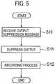
- FIG. 5 is a flowchart illustrating the control method according to the embodiment.
- step S10 the PCS 130 receives the output suppression message.
- step S11 the PCS 130 suppresses the output of the solar cell 110 according to the output suppression message.
- the PCS 130 performs a control of increasing the output of the solar cell 110 to exceed the suppression power threshold. The control is described in detail, as above.
- step S12 the PCS 130 accumulates the accumulated value of the output power of the solar cell 110 for each accumulation period (30 minutes, for example), and outputs the accumulated value accumulated for each accumulation period as the verification record.
- the verification record is recorded in the recording apparatus 500.
- the PCS 130 performs a control of increasing the output of the solar cell 110 to exceed the suppression power threshold, when there is, in the accumulation period, a period where the output of the solar cell 110 falls below the suppression power threshold. Therefore, even when there occurs a situation where the output of the solar cell 110 is inevitably smaller than the suppression power threshold due to a predetermined factor such as an insufficient solar radiation, the output of the solar cell 110 may be increased so as to exceed the suppression power threshold value to alleviate a disadvantage of a user.
- the output suppression message is a message for suppressing the reverse power flow to the power grid side, and thus, it may suffice that the reverse power flow to the power grid side is suppressed according to the output suppression message.
- a power converting apparatus that converts not only the DC power input from the above-described distributed power source but also a DC power input from a storage battery to an AC power.
- the power converting apparatus includes: an inverter that converts a DC power input from the distributed power source to an AC power, converts a DC power input from the storage battery to an AC power, and converts the AC power to a DC power output to the storage battery; and a controller that suppresses an output of the distributed power source to equal to or lower than a suppression power threshold indicating a suppression degree for the output of the distributed power source; in which the controller performs a control of increasing the output of the distributed power source to exceed the suppression power threshold, in an accumulation period included in a suppression period in which the output of the distributed power source is suppressed, when the storage battery is charged with the output of the distributed power source.
- the controller performs a control of increasing the output of the distributed power source to exceed the suppression power threshold, when the storage battery is charged with the output of the distributed power source in the accumulation period. Therefore, when the reverse power flow to the power grid is concerned, a situation is prevented where the output of the distributed power source is excessively suppressed in spite of the decrease of the output of the power converting apparatus due to the charging of the storage battery, and thus, it is possible to alleviate the disadvantage to a user.
- the controller 134 when the storage battery 120 is charged with the output of the solar cell 110 in the accumulation period included in the suppression period in which the output of the solar cell 110 is suppressed, the controller 134 performs a control of increasing the output of the solar cell 110 to exceed the suppression power threshold.
- the output of the PCS 130 is decreased due to the charging of the storage battery 120, and thus, the controller 134 temporarily increases the output of the solar cell 110 to alleviate the suppression of the output of the solar cell 110 with the charging of the storage battery 120.
- the suppression period is defined, based on the output suppression message or the schedule (calendar).
- the controller 134 performs a control of ensuring, in the accumulation period, the accumulated value of the outputs of the solar cell 110 exceeding the suppression power threshold not to exceed the charge amount of the storage battery 120. It should be noted that as a result, when the reverse power flow to the power grid 10 is concerned, the suppression of the output of the solar cell 110 is correctly executed.
- the controller 134 may perform the control before the storage battery 120 is charged. In such a case, the controller 134 performs the control on the basis of a storage capability of the storage battery 120. It should be noted however that the controller 134 performs the control of ensuring the accumulated value of the output of the solar cell 110 exceeding the suppression power threshold not to exceed the storage capability.
- the controller 134 may perform the control after the storage battery 120 is charged. In such a case, the controller 134 performs the control on the basis of a currently stored amount of the storage battery 120. It should be noted however that the controller 134 performs the control of ensuring the accumulated value of the output of the solar cell 110 exceeding the suppression power threshold not to exceed the currently stored amount.
- the controller 134 controls the output of the solar cell 110 so as to approach a target power (MPPT method). It should be noted that the controller 134 sets the suppression power threshold to the target power, in the suppression period, and sets a maximum power outside the suppression period to the target power. However, it should be noted that when performing the control even in the suppression period, the controller 134 sets a value higher than the suppression power threshold to the target power.
- MPPT method target power
- the controller 134 outputs a verification record to verify whether or not the suppression of the output of the solar cell 110 is correctly executed according to the output suppression message.
- the verification record is the accumulated value of outputs of the PCS 130 (inverter 133) in the accumulation period (30 minutes, for example) included in the suppression period.
- the controller 134 accumulates the accumulated value of the output power of the PCS 130 (inverter 133) for each accumulation period (30 minutes, for example), and outputs the accumulated value accumulated for each accumulation period as the verification record.
- the communication unit 135 communicates with the remote controller 210. For example, the communication unit 135 receives the output suppression message notified from the external server 400. The communication unit 135 transmits to the recording apparatus 500 the verification record output from the controller 134.
- Fig. 6 and Fig. 7 are diagrams for describing one example of the control according to another embodiment.
- Fig. 6 illustrates a case, as an example, where the output suppression message is notified at a time t0 and the output suppression release message is notified at a time t2.
- the output suppression release message is a message instructing a suppression release of the output of the solar cell 110.
- the output suppression message is a message instructing suppression of the output of the solar cell 110 to W1 or less.
- the suppression power threshold decreases gradually at a previously determined decrease rate.
- the output suppression message is transmitted simultaneously to a plurality of PCSs, and thus, the decrease rate is previously determined to suppress a rapid decrease of an amount of reverse power flow to the power grid 10.
- the suppression power threshold increases gradually at a previously determined increase rate.
- the output suppression release message is transmitted simultaneously to a plurality of PCSs, and thus, the increase rate is previously determined to suppress a rapid decrease of an amount of reverse power flow to the power grid 10.
- Fig. 7 in the accumulation period from a time t x to a time t x+1 , the power is stored in the storage battery 120.
- the output of the solar cell 110 (possible power generation) exceeds the suppression power threshold over a whole accumulation period, for example.
- the PCS 130 performs a control of increasing the output of the solar cell 110 to exceed the suppression power threshold. It should be noted however that the accumulated value (area S2) of the output of the solar cell 110 exceeding the suppression power threshold does not exceed the charge amount (area S1) of the storage battery 120.
- Fig. 7 illustrates, as an example, a case where the control is performed before the storage battery 120 is charged. Therefore, the charge amount (area S1) of the storage battery 120 is a storage capability of the storage battery 120.
- FIG. 8 is a flowchart illustrating the control method according to the other embodiment.
- step S10 the PCS 130 receives an output suppression message.
- step S11 the PCS 130 suppresses the output of the solar cell 110 according to the output suppression message.
- the PCS 130 performs a control of increasing the output of the solar cell 110 to exceed the suppression power threshold. The control is described in detail, as above.
- step S12 the PCS 130 accumulates the accumulated value of the output of the PCS 130 (inverter 133) for each accumulation period (30 minutes, for example), and outputs the accumulated value accumulated for each accumulation period as the verification record.
- the verification record is recorded in the recording apparatus 500.
- the PCS 130 when the storage battery 120 is charged with the output of the solar cell 110 in the accumulation period, the PCS 130 performs a control of increasing the output of the solar cell 110 to exceed the suppression power threshold. Therefore, when the reverse power flow to the power grid is concerned, a situation is prevented where the output of the solar cell 110 is excessively suppressed in spite of the decrease of the output of the PCS 130 due to the charging of the storage battery 120, and thus, it is possible to alleviate the disadvantage to a user.
- a period (hereinafter, excess period) during which the output of the solar cell 110 continuously exceeds the suppression power threshold is equal to or less than a previously determined period (5 minutes, for example).
- the PCS 130 controls the PCS 130 (controller 134) performs a correction control of ensuring the excess period not to exceed the previously determined period even when the output of the solar cell 110 (possible power generation) exceeds the suppression power threshold for a long period of time. As a result, an influence such as the reverse power flow to the power grid 10 is alleviated.
- an amount by which the output of the distributed power source exceeds the suppression power threshold is equal to or less than a previously determined amount (the suppression power threshold + 5%, for example).
- the PCS 130 controls the PCS 130 (controller 134) performs a correction control of ensuring the excess amount not to exceed the previously determined amount even when the output of the solar cell 110 (possible power generation) greatly exceeds the suppression power threshold. As a result, an influence such as the reverse power flow to the power grid 10 is alleviated.
- the consumer's facility 100 does not have the EMS 200 and the remote controller 210, as illustrated in Fig. 11 .
- the PCS 130 (communication unit 135) is directly connected to the network 300, and communicates with the external server 400 and the recording apparatus 500. Therefore, the PCS 130 (communication unit 135) transmits the verification record output from the controller 134 to the recording apparatus 500 while skipping the remote controller 210 and the EMS 200.
- the PCS 130 includes a recording unit 136, as illustrated in Fig. 12 .
- the recording unit 136 records, in much the same way as the recording apparatus 500 does, the verification record to verify whether or not the suppression of the output of the distributed power source is correctly executed according to the output suppression message. It should be noted that in such a case, the recording unit 136 records the verification record output from the controller 134.
- the recording unit 136 that records the verification record is provided in the PCS 130, and thus, the power management system 1 need not to include the recording apparatus 500.
- the embodiments provide an example of the PCS 130 connected to the solar cell 110 and the storage battery 120; however, this is not limiting. It is possible that the PCS 130 is not connected to the storage battery 120 but connected only to the solar cell 110.
- the embodiments provide an example of the solar cell 110 as the distributed power source to operate in accordance with the output suppression message.
- the distributed power source is not limited thereto.
- the distributed power source may be an equipment that utilizes a natural energy such as a wind power and a geothermal heat to generate power.
- the distributed power source may be a fuel cell that utilizes a fuel gas to produce power.
- the controller 134 controls the PCS 130.
- the controller 134 may control the PCS 130 according to an instruction from the EMS 200 or the remote controller 210. That is, a controller (functional block including a similar function to the controller 134) that suppresses the output of the distributed power source to equal to or less than the suppression power threshold determined by the output suppression message may be provided in the EMS 200 or the remote controller 210.
- the recording unit 136 that records the verification record is provided in the PCS 130.
- the embodiment is not limited thereto.
- the recording unit 136 that records the verification record may be provided in the EMS 200 or the remote controller 210.
Landscapes
- Engineering & Computer Science (AREA)
- Power Engineering (AREA)
- Life Sciences & Earth Sciences (AREA)
- Sustainable Development (AREA)
- Sustainable Energy (AREA)
- Physics & Mathematics (AREA)
- Electromagnetism (AREA)
- General Physics & Mathematics (AREA)
- Radar, Positioning & Navigation (AREA)
- Automation & Control Theory (AREA)
- Supply And Distribution Of Alternating Current (AREA)
Abstract
Description
- The present invention relates to a power converting apparatus that converts a DC power to an AC power, a power management system including the power converting apparatus, and a power converting method.
- A power converting apparatus (power conditioner) connected to a distributed power source that outputs a DC power is known. The power converting apparatus includes a DC convertor (DC/DC convertor) that converts a voltage of a DC power input from the distributed power source; and an inverter that converts the DC power input from the DC convertor to an AC power (for example, Patent Document 1).
- Here, upon reception of a message instructing suppression of output of the distributed power source (hereinafter, "output suppression message"), the power converting apparatus needs to suppress the output of the distributed power source to equal to or less than a suppression power threshold defined by the output suppression message.
- Patent Document 1: Japanese Application Publication No.
2014-171359 - According to one aspect, a power converting apparatus comprises an inverter that converts a DC (Direct Current) power input from a distributed power source to an AC (Alternating Current) power; and a controller that suppresses an output of the distributed power source to equal to or lower than a suppression power threshold indicating a suppression degree for the output of the distributed power source. The controller performs a control of increasing the output of the distributed power source to exceed the suppression power threshold, when there is a period, where the output of the distributed power source falls below the suppression power threshold, in an accumulation period included in a suppression period in which the output of the distributed power source is suppressed.
- According to one aspect, a power management system comprises a power converting apparatus that converts a DC power input from a distributed power source to an AC power; and a controller that suppresses an output of the distributed power source equal to or lower than a suppression power threshold indicating a suppression degree for the output of the distributed power source. The controller performs a control of increasing the output of the distributed power source to exceed the suppression power threshold, when there is a period, where the output of the distributed power source falls below the suppression power threshold, in an accumulation period included in a suspension period for suppressing the output of the distributed power source.
- According to one aspect, a power converting apparatus comprises an inverter that converts a DC power input from a distributed power source to an AC power, converts a DC power input from a storage battery to an AC power, and converts a AC power to a DC power output to the storage battery; and a controller that suppresses an output of the distributed power source equal to or lower than a suppression power threshold indicating a suppression degree for the output of the distributed power source. The controller performs a control of increasing the output of the distributed power source to exceed the suppression power threshold, in an accumulation period included in a suppression period in which the output of the distributed power source is suppressed, when the storage battery is charged with the output of the distributed power source.
- According to one aspect, a power management system comprises a power converting apparatus that converts a DC power input from a distributed power source to an AC power, converts a DC power input from a storage battery to an AC power, and converts a AC power to a DC power output to the storage battery; and a controller that suppresses an output of the distributed power source equal to or lower than a suppression power threshold indicating a suppression degree for the output of the distributed power source. The controller performs a control of increasing the output of the distributed power source to exceed the suppression power threshold, in an accumulation period included in a suppression period in which the output of the distributed power source is suppressed, when the storage battery is charged with the output of the distributed power source.
- According to one aspect, a power converting method, comprising the steps of: converting a DC power input from a distributed power source to an AC power, converting a DC power input from a storage battery to an AC power, and converting a AC power to a DC power output to the storage battery; suppressing an output of the distributed power source to equal to or lower than a suppression power threshold indicating a suppression degree for the output of the distributed power source; and performing a control of increasing the output of the distributed power source so that the output of the distributed power source exceeds the suppression power threshold, in an accumulation period included in a suppression period in which the output of the distributed power source is suppressed, when the storage battery is charged with the output of the distributed power source.
-
-
Fig. 1 is a diagram illustrating apower management system 1 according to an embodiment. -
Fig. 2 is a diagram illustrating aPCS 130 according to the embodiment. -
Fig. 3 is a graph for describing a control according to the embodiment. -
Fig. 4 is a graph for describing a control signal according to the embodiment. -
Fig. 5 is a flowchart illustrating a control method according to the embodiment. -
Fig. 6 is a graph for describing a control according to another embodiment. -
Fig. 7 is a graph for describing a control according to another embodiment. -
Fig. 8 is a flowchart illustrating a control method according to another embodiment. -
Fig. 9 is a graph for describing a control according to another embodiment. -
Fig. 10 is a graph for describing a control according to another embodiment. -
Fig. 11 is a diagram illustrating thepower management system 1 according to another embodiment. -
Fig. 12 is a diagram illustrating thePCS 130 according to another embodiment. - An embodiment is described below by referring to the drawings. In the following description of the drawings, same or similar reference numerals are given to denote same or similar portions.
- Note that the drawings are merely schematically shown and proportions of sizes and the like are different from actual ones. Thus, specific sizes and the like should be judged by referring to the description below. In addition, there are of course included portions where relationships or ratios of sizes of the drawings are different with respect to one another.
- In the above-described conventional technology, after the output suppression message is received, the output of the distributed power source may be inevitably smaller than the suppression power threshold due to a predetermined factor. For example, when the distributed power source is a solar cell apparatus, the predetermined factor may include an insufficient solar radiation. Alternatively, when the distributed power source is a wind energy conversion system, the predetermined factor may include an insufficient amount of winds. Such a situation is greatly disadvantageous to a user.
- In embodiment, a power converting apparatus comprises an inverter that converts a DC (Direct Current) power input from a distributed power source to an AC (Alternating Current) power; and a controller that suppresses an output of the distributed power source to equal to or lower than a suppression power threshold indicating a suppression degree for the output of the distributed power source. The controller performs a control of increasing the output of the distributed power source to exceed the suppression power threshold, when there is a period, where the output of the distributed power source falls below the suppression power threshold, in an accumulation period included in a suppression period in which the output of the distributed power source is suppressed.
- In the embodiment, the controller performs a control of increasing the output of the distributed power source to exceed the suppression power threshold, when there is, in an accumulation period, a period where the output of the distributed power source falls below the suppression power threshold value. Therefore, even when there occurs a situation where the output of the distributed power source is inevitably smaller than the suppression power threshold value due to a predetermined factor such as an insufficient solar radiation, the output of the distributed power source may be increased to exceed the suppression power threshold value to alleviate a disadvantage of a user.
- A power management system according to an embodiment will be described, below.
Fig. 1 is a diagram illustrating thepower management system 1 according to the embodiment. - As illustrated in
Fig. 1 , thepower management system 1 includes a consumer'sfacility 100, anexternal server 400, and arecording apparatus 500. The consumer'sfacility 100 has an EMS 200, and the EMS 200 communicates with theexternal server 400 and therecording apparatus 500 via anetwork 300. - The consumer's
facility 100 includes asolar cell 110, astorage battery 120, aPCS 130, adistribution board 140, and aload 150. Furthermore, the consumer'sfacility 100 includes the EMS 200 and aremote controller 210. - The
solar cell 110 is an equipment that generates power in response to reception of solar light. Thesolar cell 110 outputs the generated DC power. An amount of power to be generated by thesolar cell 110 varies depending on an amount of the solar radiation entering thesolar cell 110. Thesolar cell 110 is an example of a distributed power source to operate in accordance with an output suppression message described later. - The
storage battery 120 is an equipment in which power is accumulated. Thestorage battery 120 outputs the accumulated DC power. It should be noted that in the embodiment, thestorage battery 120 needs not to operate in accordance with the output suppression message described later. - The PCS 130 (PCS: Power Conditioning System) is an example of a power converting apparatus that converts a DC power to an AC power. In the embodiment, the PCS 130 is connected to a main power line 10L (herein, a main power line 10LA and a main power line 10LB) connected to a
power grid 10, and connected to both thesolar cell 110 and thestorage battery 120. The main power line 10LA is a power line connecting thepower grid 10 and the PCS 130, and the main power line 10LB is a power line connecting the PCS 130 and thedistribution board 140. - Here, the PCS 130 converts the DC power input from the
solar cell 110 to an AC power, and converts the DC power input from thestorage battery 120 to an AC power. Furthermore, the PCS 130 converts an AC power supplied from thepower grid 10 to a DC power. - The
distribution board 140 is connected to the main power line 10L (herein, the main power line 10LB). Thedistribution board 140 divides the main power line 10LB into a plurality of power lines, and distributes the power to an equipment (herein, theload 150 and the EMS 200) connected to the plurality of power lines. - The
load 150 is an equipment in which the power supplied via the power line is consumed. Examples of theload 150 include an equipment such as a refrigerator, a lighting, an air conditioner, and a TV. Theload 150 may be a single equipment, and may include a plurality of equipments. - The
EMS 200 is an equipment (EMS: Energy Management System) that manages power information indicating the power supplied to the consumer'sfacility 100 from thepower grid 10. TheEMS 200 may manage an amount of power to be generated by thesolar cell 110, an amount of power to be stored in thestorage battery 120, and an amount of power to be discharged from thestorage battery 120. - In the embodiment, the
EMS 200 is connected to theremote controller 210 and thenetwork 300. For example, theEMS 200 receives the power suppression message described later from theexternal server 400, and notifies theremote controller 210 of the power suppression message. Alternatively, theEMS 200 receives a schedule (calendar) described later from theexternal server 400, and based on the schedule (calendar), notifies theremote controller 210 of the power suppression message. - The
PCS 130 has theremote controller 210 provided in connection with thePCS 130, and theremote controller 210 notifies thePCS 130 of various types of messages to operate thePCS 130. For example, theremote controller 210 notifies thePCS 130 of the power suppression message received from theEMS 200. - The
network 300 is a communication network by which theEMS 200, theexternal server 400, and therecording apparatus 500 are connected. Thenetwork 300 may be the Internet. Thenetwork 300 may include a mobile communication network. - The
external server 400 notifies the output suppression message that is a message to instruct suppression of the output of the distributed power source (herein, the solar cell 110). Here, theexternal server 400 may manage a schedule (calendar), as a whole of thepower grid 10, including a date and time for suppressing the output of the distributed power source. Theexternal server 400 notifies the output suppression message, based on such a schedule (calendar). Alternatively, theexternal server 400 may notify theEMS 200 of such a schedule (calendar). - Here, the output suppression message and the schedule (calendar) include information indicating a suppression degree (an output suppression power threshold, for example) for the output of the distributed power source (herein, the solar cell 110). The suppression degree may be represented by an absolute value (xx kW, for example) of the output of the distributed power source (herein, the solar cell 110). Alternatively, the suppression degree may be represented by a relative value (decrease by xx kW, for example) of the output of the distributed power source (herein, the solar cell 110). Alternatively, the suppression degree may be represented by a suppression rate (xx%, for example) of the output of the distributed power source (herein, the solar cell 110). The suppression rate preferably is a rate of the distributed power source relative to the output certified, as an output capability of the PCS that controls the distributed power source (hereinafter, facility certified output), when the distributed power source is installed in the consumer's
facility 100. If the output capability of the distributed power source and that of the PCS differ, either one of a smaller output capability is selected, as the facility certified output. When a plurality of PCSs are installed, the facility certified output is a sum of the output capabilities of the plurality of PCSs. - The
recording apparatus 500 is an equipment that records various types of information. Specifically, therecording apparatus 500 records a verification record to verify whether or not the suppression of the output of the distributed power source is correctly executed according to the output suppression message. The verification record is an accumulated value of outputs of the distributed power source in an accumulation period (30 minutes, for example) included in the suppression period in which the output of the distributed power source is suppressed by the output suppression message. In such a case, in the verification record accumulated for each accumulation period, the suppression of the output of the distributed power source may be correctly executed. - The power converting apparatus according to the embodiment will be described below.
Fig. 2 is a diagram illustrating thePCS 130 according to the embodiment. - As illustrated in
Fig. 2 , thePCS 130 is connected to apower line 11L connected to the main power line 10LA, and apower line 12L connected to the main power line 10LB. Furthermore, apower line 13L connecting thepower line 11L and thepower line 12L is provided. Thepower line 13L is connected closer to thepower line 11L at the main power line 10LA side than a switch 11SW, and connected closer to thepower line 12L at the main power line 10LB than a switch 12SW. - The
power line 11L is a power line connecting thepower grid 10 and aninverter 133. Thepower line 11L may be a power line configuring a part of the main power line 10LA, and may be a power line divided from the main power line 10LA. Thepower line 12L is a power line connecting theinverter 133 and the distribution board 140 (load 150). Thepower line 12L may be a power line configuring a part of the main power line 10LB, and may be a power line divided from the main power line 10LB. - The
PCS 130 includes the switch 11SW provided on thepower line 11L, the switch 12SW provided on thepower line 12L, and a switch 13SW provided on thepower line 13L. - The switch 11SW is controlled to be in a closed state in a grid connected state in which the
PCS 130 is connected to thepower grid 10. On the other hand, the switch 11SW is controlled to be in an opened state in a self-sustained state in which thePCS 130 parallels off thepower grid 10. - The switch 12SW is controlled to be in an opened state in a grid connected state in which the
PCS 130 is connected to thepower grid 10. On the other hand, the switch 11SW is controlled to be in a closed state in a self-sustained state in which thePCS 130 is disconnected from thepower grid 10. - The switch 13SW is controlled to be in a closed state in a grid connected state in which the distribution board 140 (load 150) is connected to the
power grid 10. Likewise, the switch 13SW is controlled to be in a closed state in a grid connected state in which thePCS 130 is connected to thepower grid 10. On the other hand, the switch 13SW is controlled to be in an opened state in a self-sustained state in which the distribution board 140 (load 150) is disconnected from thepower grid 10. Likewise, the switch 13SW is controlled to be in an opened state in a self-sustained state in which thePCS 130 is disconnected from thepower grid 10. - Generally, in the grid connected state in which the consumer's
facility 100 is connected to thepower grid 10, both thePCS 130 and the distribution board 140 (load 150) are connected to thepower grid 10. Therefore, in such a grid connected state, the switch 11SW and the switch 13SW are controlled to be in a closed state, and the switch 12SW is controlled to be in an opened state. On the other hand, generally, in the self-sustained state in which the consumer'sfacility 100 is disconnected from thepower grid 10, both thePCS 130 and the distribution board 140 (load 150) are not connected to thepower grid 10. Therefore, in such a self-sustained state, the switch 11SW and the switch 13SW are controlled to be in an opened state, and the switch 12SW is controlled to be in a closed state. - As illustrated in
Fig. 2 , thePCS 130 includes a DC/DC convertor 131, a DC/DC convertor 132, theinverter 133, acontroller 134, and acommunication unit 135. - The DC/
DC convertor 131 is a first direct current convertor that converts a voltage of a DC power input from thesolar cell 110. The DC/DC convertor 131 may upconvert the voltage of the DC power and downconvert the voltage of the DC power. - The DC/
DC convertor 132 is a second direct current convertor that converts a voltage of a DC power input from thestorage battery 120. Furthermore, the DC/DC convertor 132 converts a voltage of the DC power input from theinverter 133. The DC/DC convertor 132 may upconvert the voltage of the DC power and may downconvert the voltage of the DC power. - It should be noted here that an operation of outputting the DC power from the
storage battery 120 to the DC/DC convertor 132 is discharge from thestorage battery 120. It should be noted that an operation of outputting the DC power from the DC/DC convertor 132 to thestorage battery 120 is charge into thestorage battery 120. - The
inverter 133 converts the DC power input from the DC/DC convertor 131 and the DC power input from the DC/DC convertor 132, to an AC power. Furthermore, theinverter 133 converts the AC power supplied from thepower grid 10 to a DC power. - The
controller 134 controls thePCS 130. Firstly, thecontroller 134 controls an amount of power generated by thesolar cell 110. In particular, thecontroller 134 controls the output of thesolar cell 110 to approach a target power (MPPT (Maximum Power Point Tracking), for example). As a result, an operation point (point determined by an operation-point voltage value and power value, or a point determined by an operation-point voltage value and electric current value) of thesolar cell 110 is optimized. Secondly, thecontroller 134 controls the charge amount and the discharge amount in thestorage battery 120. - Here, the
controller 134 suppresses the output of thesolar cell 110 according to the output suppression message or the schedule (calendar). As described above, the suppression degree may be represented by an absolute value (xx kW, for example) of the output of thesolar cell 110. Alternatively, the suppression degree may be represented by a relative value (decrease by xx kW, for example) of the output of thesolar cell 110. Alternatively, the suppression degree may be represented with a suppression rate (xx%, for example) of the output of thesolar cell 110. - In the embodiment, if there is a period during which the output of the
solar cell 110 falls below the suppression power threshold (hereinafter, insufficient output period), in the accumulation period included in the suppression period in which the output of thesolar cell 110 is suppressed, thecontroller 134 performs a control of increasing the output of thesolar cell 110 to exceed the suppression power threshold. That is, in the control, in oder to compensate the output of thesolar cell 110 decreasing than the suppression power threshold in an insufficient output period, thecontroller 134 temporarily increases the output of thesolar cell 110. The suppression period is defined, based on the output suppression message or the schedule (calendar). - Here, the insufficient output period is a period during which the output of the
solar cell 110 is inevitably smaller than the suppression power threshold due to a predetermined factor. The predetermined factor is an insufficient solar radiation, for example. - In the embodiment, the
controller 134 performs a control of ensuring the accumulated value of the outputs of thesolar cell 110 not to exceed, in the accumulation period, the accumulated value of the suppression power thresholds. In other words, thecontroller 134 controls so that an average value of the outputs of thesolar cell 110 does not exceed, in the accumulation period, an average value of the suppression power thresholds. It should be noted that as a result, in the verification record accumulated for each accumulation period, the suppression of the output of thesolar cell 110 is correctly executed. - Here, as described above, the
controller 134 controls the output of thesolar cell 110 so as to approach a target power (MPPT method). It should be noted that thecontroller 134 sets the suppression power threshold to the target power, in the suppression period, and sets a maximum power outside the suppression period to the target power. However, it should be noted that when performing the control even in the suppression period, thecontroller 134 sets a value higher than the suppression power threshold to the target power. - The
controller 134 outputs a verification record to verify whether or not the suppression of the output of thesolar cell 110 is correctly executed according to the output suppression message. As described above, the verification record is an accumulated value of outputs of thesolar cell 110 in the accumulation period (30 minutes, for example) included in the suppression period. Thecontroller 134 accumulates the accumulated value of the output power of thesolar cell 110 for each accumulation period (30 minutes, for example), and outputs the accumulated value accumulated for each accumulation period as the verification record. - The
communication unit 135 communicates with theremote controller 210. For example, thecommunication unit 135 receives the output suppression message notified from theexternal server 400. Thecommunication unit 135 transmits to therecording apparatus 500 the verification record output from thecontroller 134. - An example of control according to the embodiment will be described below.
Fig. 3 and Fig. 4 are diagrams for describing an example of the control according to the embodiment. - Firstly, the suppression power threshold will be described with reference to
Fig. 3. Fig. 3 illustrates a case where the output suppression message is notified at a time t0 and an output suppression release message is notified at a time t2. The output suppression release message is a message instructing a suppression release of the output of thesolar cell 110. Here, the output suppression message is a message instructing suppression of the output of thesolar cell 110 to W1 or less. - In such a case, in a period from the time t0 to the time t1, the suppression power threshold decreases gradually at a previously determined decrease rate. The output suppression message is transmitted simultaneously to a plurality of PCSs, and thus, the decrease rate is previously determined to suppress a rapid decrease of an amount of reverse power flow to the
power grid 10. On the other hand, after the time t2, the suppression power threshold increases gradually at a previously determined increase rate. The output suppression release message is transmitted simultaneously to a plurality of PCSs, and thus, the increase rate is previously determined to suppress a rapid decrease of an amount of reverse power flow to thepower grid 10. - Secondly, the control will be described with reference to
Fig. 4 . InFig. 4 , in the accumulation period from a time tx to a time tx+1, there is a period (insufficient output period) during which the output of the solar cell 110 (possible power generation) falls below the suppression power threshold. The output of the solar cell 110 (possible power generation) decreases, for example, due to a temporal insufficient solar radiation, and outside the insufficient output period, exceeds the suppression power threshold. - In such a case, the
PCS 130 performs a control of increasing the output of thesolar cell 110 to exceed the suppression power threshold. It is noted that the accumulated value (area S2) of the output of thesolar cell 110 exceeding the suppression power threshold does not exceed the accumulated value (area S1) of the output of thesolar cell 110 falling below the suppression power threshold in the insufficient output period. - A control method according to the embodiment will be described below.
Fig. 5 is a flowchart illustrating the control method according to the embodiment. - As illustrated in
Fig. 5 , in step S10, thePCS 130 receives the output suppression message. - In step S11, the
PCS 130 suppresses the output of thesolar cell 110 according to the output suppression message. Here, when there is an insufficient output period in the accumulation period included in the suppression period, thePCS 130 performs a control of increasing the output of thesolar cell 110 to exceed the suppression power threshold. The control is described in detail, as above. - In step S12, the
PCS 130 accumulates the accumulated value of the output power of thesolar cell 110 for each accumulation period (30 minutes, for example), and outputs the accumulated value accumulated for each accumulation period as the verification record. The verification record is recorded in therecording apparatus 500. - In the embodiment, the
PCS 130 performs a control of increasing the output of thesolar cell 110 to exceed the suppression power threshold, when there is, in the accumulation period, a period where the output of thesolar cell 110 falls below the suppression power threshold. Therefore, even when there occurs a situation where the output of thesolar cell 110 is inevitably smaller than the suppression power threshold due to a predetermined factor such as an insufficient solar radiation, the output of thesolar cell 110 may be increased so as to exceed the suppression power threshold value to alleviate a disadvantage of a user. - Another embodiment will be described, below. A difference from the above-described embodiment will be described, below.
- In the above-described conventional technology, the output suppression message is a message for suppressing the reverse power flow to the power grid side, and thus, it may suffice that the reverse power flow to the power grid side is suppressed according to the output suppression message. Further, also known is a power converting apparatus that converts not only the DC power input from the above-described distributed power source but also a DC power input from a storage battery to an AC power.
- Here, a case is assumed where in such a power converting apparatus, while suppressing the output of the distributed power source to equal to or less than the suppression power threshold determined by the output suppression message, the storage battery is charged with the output of the distributed power source. In such a case, when the reverse power flow to the power grid is concerned, a situation may occur where the output of the distributed power source is excessively suppressed in spite of the decrease of the output of the power converting apparatus due to the charging of the storage battery. Such a situation is greatly disadvantageous to a user.
- The power converting apparatus according to another embodiment includes: an inverter that converts a DC power input from the distributed power source to an AC power, converts a DC power input from the storage battery to an AC power, and converts the AC power to a DC power output to the storage battery; and a controller that suppresses an output of the distributed power source to equal to or lower than a suppression power threshold indicating a suppression degree for the output of the distributed power source; in which the controller performs a control of increasing the output of the distributed power source to exceed the suppression power threshold, in an accumulation period included in a suppression period in which the output of the distributed power source is suppressed, when the storage battery is charged with the output of the distributed power source.
- In the other embodiment, the controller performs a control of increasing the output of the distributed power source to exceed the suppression power threshold, when the storage battery is charged with the output of the distributed power source in the accumulation period. Therefore, when the reverse power flow to the power grid is concerned, a situation is prevented where the output of the distributed power source is excessively suppressed in spite of the decrease of the output of the power converting apparatus due to the charging of the storage battery, and thus, it is possible to alleviate the disadvantage to a user.
- In another embodiment, when the
storage battery 120 is charged with the output of thesolar cell 110 in the accumulation period included in the suppression period in which the output of thesolar cell 110 is suppressed, thecontroller 134 performs a control of increasing the output of thesolar cell 110 to exceed the suppression power threshold. When the reverse power flow to thepower grid 10 is concerned, the output of thePCS 130 is decreased due to the charging of thestorage battery 120, and thus, thecontroller 134 temporarily increases the output of thesolar cell 110 to alleviate the suppression of the output of thesolar cell 110 with the charging of thestorage battery 120. The suppression period is defined, based on the output suppression message or the schedule (calendar). - In the other embodiment, the
controller 134 performs a control of ensuring, in the accumulation period, the accumulated value of the outputs of thesolar cell 110 exceeding the suppression power threshold not to exceed the charge amount of thestorage battery 120. It should be noted that as a result, when the reverse power flow to thepower grid 10 is concerned, the suppression of the output of thesolar cell 110 is correctly executed. - In the other embodiment, the
controller 134 may perform the control before thestorage battery 120 is charged. In such a case, thecontroller 134 performs the control on the basis of a storage capability of thestorage battery 120. It should be noted however that thecontroller 134 performs the control of ensuring the accumulated value of the output of thesolar cell 110 exceeding the suppression power threshold not to exceed the storage capability. - Alternatively, the
controller 134 may perform the control after thestorage battery 120 is charged. In such a case, thecontroller 134 performs the control on the basis of a currently stored amount of thestorage battery 120. It should be noted however that thecontroller 134 performs the control of ensuring the accumulated value of the output of thesolar cell 110 exceeding the suppression power threshold not to exceed the currently stored amount. - Here, as described above, the
controller 134 controls the output of thesolar cell 110 so as to approach a target power (MPPT method). It should be noted that thecontroller 134 sets the suppression power threshold to the target power, in the suppression period, and sets a maximum power outside the suppression period to the target power. However, it should be noted that when performing the control even in the suppression period, thecontroller 134 sets a value higher than the suppression power threshold to the target power. - The
controller 134 outputs a verification record to verify whether or not the suppression of the output of thesolar cell 110 is correctly executed according to the output suppression message. As described above, the verification record is the accumulated value of outputs of the PCS 130 (inverter 133) in the accumulation period (30 minutes, for example) included in the suppression period. Thecontroller 134 accumulates the accumulated value of the output power of the PCS 130 (inverter 133) for each accumulation period (30 minutes, for example), and outputs the accumulated value accumulated for each accumulation period as the verification record. - The
communication unit 135 communicates with theremote controller 210. For example, thecommunication unit 135 receives the output suppression message notified from theexternal server 400. Thecommunication unit 135 transmits to therecording apparatus 500 the verification record output from thecontroller 134. - One example of the control according to another embodiment will be described, below.
Fig. 6 and Fig. 7 are diagrams for describing one example of the control according to another embodiment. - Firstly, the suppression power threshold will be described with reference to
Fig. 6. Fig. 6 illustrates a case, as an example, where the output suppression message is notified at a time t0 and the output suppression release message is notified at a time t2. The output suppression release message is a message instructing a suppression release of the output of thesolar cell 110. Here, the output suppression message is a message instructing suppression of the output of thesolar cell 110 to W1 or less. - In such a case, in a period from the time t0 to the time t1, the suppression power threshold decreases gradually at a previously determined decrease rate. The output suppression message is transmitted simultaneously to a plurality of PCSs, and thus, the decrease rate is previously determined to suppress a rapid decrease of an amount of reverse power flow to the
power grid 10. On the other hand, after the time t2, the suppression power threshold increases gradually at a previously determined increase rate. The output suppression release message is transmitted simultaneously to a plurality of PCSs, and thus, the increase rate is previously determined to suppress a rapid decrease of an amount of reverse power flow to thepower grid 10. - Secondly, the control will be described with reference to
Fig. 7 . InFig. 7 , in the accumulation period from a time tx to a time tx+1, the power is stored in thestorage battery 120. The output of the solar cell 110 (possible power generation) exceeds the suppression power threshold over a whole accumulation period, for example. - In such a case, the
PCS 130 performs a control of increasing the output of thesolar cell 110 to exceed the suppression power threshold. It should be noted however that the accumulated value (area S2) of the output of thesolar cell 110 exceeding the suppression power threshold does not exceed the charge amount (area S1) of thestorage battery 120. -
Fig. 7 illustrates, as an example, a case where the control is performed before thestorage battery 120 is charged. Therefore, the charge amount (area S1) of thestorage battery 120 is a storage capability of thestorage battery 120. - A control method according to another embodiment will be described below.
Fig. 8 is a flowchart illustrating the control method according to the other embodiment. - As illustrated in
Fig. 8 , in step S10, thePCS 130 receives an output suppression message. - In step S11, the
PCS 130 suppresses the output of thesolar cell 110 according to the output suppression message. Here, when there is an insufficient output period in the accumulation period included in the suppression period, thePCS 130 performs a control of increasing the output of thesolar cell 110 to exceed the suppression power threshold. The control is described in detail, as above. - In step S12, the
PCS 130 accumulates the accumulated value of the output of the PCS 130 (inverter 133) for each accumulation period (30 minutes, for example), and outputs the accumulated value accumulated for each accumulation period as the verification record. The verification record is recorded in therecording apparatus 500. - In another embodiment, when the
storage battery 120 is charged with the output of thesolar cell 110 in the accumulation period, thePCS 130 performs a control of increasing the output of thesolar cell 110 to exceed the suppression power threshold. Therefore, when the reverse power flow to the power grid is concerned, a situation is prevented where the output of thesolar cell 110 is excessively suppressed in spite of the decrease of the output of thePCS 130 due to the charging of thestorage battery 120, and thus, it is possible to alleviate the disadvantage to a user. - Another embodiment will be described, below. A difference from the above-described embodiment will be described, below.
- Firstly, in the other embodiment, in the control, a period (hereinafter, excess period) during which the output of the
solar cell 110 continuously exceeds the suppression power threshold is equal to or less than a previously determined period (5 minutes, for example). Specifically, as illustrated inFig. 9 , the PCS 130 (controller 134) performs a correction control of ensuring the excess period not to exceed the previously determined period even when the output of the solar cell 110 (possible power generation) exceeds the suppression power threshold for a long period of time. As a result, an influence such as the reverse power flow to thepower grid 10 is alleviated. - Secondly, in the control, an amount by which the output of the distributed power source exceeds the suppression power threshold is equal to or less than a previously determined amount (the suppression power threshold + 5%, for example). Specifically, as illustrated in
Fig. 10 , the PCS 130 (controller 134) performs a correction control of ensuring the excess amount not to exceed the previously determined amount even when the output of the solar cell 110 (possible power generation) greatly exceeds the suppression power threshold. As a result, an influence such as the reverse power flow to thepower grid 10 is alleviated. - Another embodiment will be described, below. A difference from the above-described embodiment will be described, below.
- In the other embodiment, the consumer's
facility 100 does not have theEMS 200 and theremote controller 210, as illustrated inFig. 11 . The PCS 130 (communication unit 135) is directly connected to thenetwork 300, and communicates with theexternal server 400 and therecording apparatus 500. Therefore, the PCS 130 (communication unit 135) transmits the verification record output from thecontroller 134 to therecording apparatus 500 while skipping theremote controller 210 and theEMS 200. - Another embodiment will be described, below. A difference from the above-described embodiment will be described, below.
- In the other embodiment, the
PCS 130 includes arecording unit 136, as illustrated inFig. 12 . Therecording unit 136 records, in much the same way as therecording apparatus 500 does, the verification record to verify whether or not the suppression of the output of the distributed power source is correctly executed according to the output suppression message. It should be noted that in such a case, therecording unit 136 records the verification record output from thecontroller 134. - In the other embodiment, the
recording unit 136 that records the verification record is provided in thePCS 130, and thus, thepower management system 1 need not to include therecording apparatus 500. - The present invention was described in terms of the embodiment set forth above, the invention should not be understood to be limited by the statements and the drawings constituting a part of this disclosure. From this disclosure, various alternative embodiments, examples, and operational technologies will be obvious to those skilled in the art.
- The embodiments provide an example of the
PCS 130 connected to thesolar cell 110 and thestorage battery 120; however, this is not limiting. It is possible that thePCS 130 is not connected to thestorage battery 120 but connected only to thesolar cell 110. - The embodiments provide an example of the
solar cell 110 as the distributed power source to operate in accordance with the output suppression message. However, the distributed power source is not limited thereto. The distributed power source may be an equipment that utilizes a natural energy such as a wind power and a geothermal heat to generate power. Alternatively, the distributed power source may be a fuel cell that utilizes a fuel gas to produce power. - In the embodiments, the
controller 134 controls thePCS 130. In such a case, thecontroller 134 may control thePCS 130 according to an instruction from theEMS 200 or theremote controller 210. That is, a controller (functional block including a similar function to the controller 134) that suppresses the output of the distributed power source to equal to or less than the suppression power threshold determined by the output suppression message may be provided in theEMS 200 or theremote controller 210. - In the other embodiment, the
recording unit 136 that records the verification record is provided in thePCS 130. However, the embodiment is not limited thereto. Therecording unit 136 that records the verification record may be provided in theEMS 200 or theremote controller 210. - The entire contents of Japanese patent application No.
2015-035086 (filed on February 25, 2015 2015-035911 (filed on February 25, 2015
Claims (18)
- A power converting apparatus comprising:an inverter that converts a DC (Direct Current) power input from a distributed power source to an AC (Alternating Current) power; anda controller that suppresses an output of the distributed power source to equal to or lower than a suppression power threshold indicating a suppression degree for the output of the distributed power source; whereinthe controller performs a control of increasing the output of the distributed power source to exceed the suppression power threshold, when there is a period, where the output of the distributed power source falls below the suppression power threshold, in an accumulation period included in a suppression period for suppressing the output of the distributed power source.
- The power converting apparatus according to claim 1, wherein
the controller performs, in the accumulation period, the control so that an accumulated value of an output of the distributed power source does not exceed an accumulated value of the suppression power threshold. - The power converting apparatus according to claim 1 or 2, wherein
the controller performs, in the accumulation period, the control so that an average value of the output of the distributed power source does not exceed an average value of the suppression power threshold. - The power converting apparatus according to any one of claims 1 to 3, wherein
the controller controls the output of the distributed power source so as to approach a target power, and
the controller sets, in the suppression period, the suppression power threshold to the target power and sets, outside the suppression period, a maximum power to the target power. - The power converting apparatus according to any one of claims 1 to 4, wherein,
in the control, a period during which the output of the distributed power source continuously exceeds the suppression power threshold is equal to or shorter than a previously determined period. - The power converting apparatus according to any one of claims 1 to 5, wherein,
in the control, an amount by which the output of the distributed power source exceeds the suppression power threshold is equal to or less than a previously determined amount. - The power converting apparatus according to any one of claims 1 to 6, wherein
the controller outputs an accumulated value of the output of the distributed power source in the accumulation period. - A power management system comprising:a power converting apparatus that converts a DC power input from a distributed power source to an AC power; anda controller that suppresses an output of the distributed power source equal to or lower than a suppression power threshold indicating a suppression degree for the output of the distributed power source; whereinthe controller performs a control of increasing the output of the distributed power source to exceed the suppression power threshold, when there is a period, where the output of the distributed power source falls below the suppression power threshold, in an accumulation period included in a suppression period in which the output of the distributed power source is suppressed.
- A power converting apparatus comprising:an inverter that converts a DC power input from a distributed power source to an AC power, converts a DC power input from a storage battery to an AC power, and converts a AC power to a DC power output to the storage battery; anda controller that suppresses an output of the distributed power source equal to or lower than a suppression power threshold indicating a suppression degree for the output of the distributed power source; whereinthe controller performs a control of increasing the output of the distributed power source to exceed the suppression power threshold, in an accumulation period included in a suppression period in which the output of the distributed power source is suppressed, when the storage battery is charged with the output of the distributed power source.
- The power converting apparatus according to claim 9, wherein
the controller performs, in the accumulation period, the control so that an accumulated value of an excess amount by which the output of the distributed power source exceeds the suppression power threshold does not exceeds a charge amount of the storage battery. - The power converting apparatus according to claim 9 or 10, wherein
the controller performs the control on the basis of a storage capability of the storage battery when performing the control before the storage battery is charged. - The power converting apparatus according to claim 9 or 10, wherein
the controller performs the control on the basis of a currently stored amount of the storage battery when performing the control after the storage battery is charged. - The power converting apparatus according to any one of claims 9 to 12, wherein
the controller controls the output of the distributed power source so as to approach a target power, and
the controller sets, in the suppression period, the suppression power threshold to the target power and sets, outside the suppression period, a maximum power to the target power. - The power converting apparatus according to any one of claims 9 to 13, wherein,
in the control, a period during which the output of the distributed power source continuously exceeds the suppression power threshold is equal to or shorter than a previously determined period. - The power converting apparatus according to any one of claims 9 to 14, wherein,
in the control, an amount by which the output of the distributed power source exceeds the suppression power threshold is equal to or less than a previously determined amount. - The power converting apparatus according to any one of claims 9 to 15, wherein
the controller outputs an accumulated value of the output of the inverter in the accumulation period. - A power management system comprising:a power converting apparatus that converts a DC power input from a distributed power source to an AC power, converts a DC power input from a storage battery to an AC power, and converts a AC power to a DC power output to the storage battery; anda controller that suppresses an output of the distributed power source equal to or lower than a suppression power threshold indicating a suppression degree for the output of the distributed power source; whereinthe controller performs a control of increasing the output of the distributed power source to exceed the suppression power threshold, in an accumulation period included in a suppression period in which the output of the distributed power source is suppressed, when the storage battery is charged with the output of the distributed power source.
- A power converting method, comprising the steps of:converting a DC power input from a distributed power source to an AC power, converting a DC power input from a storage battery to an AC power, and converting a AC power to a DC power output to the storage battery;suppressing an output of the distributed power source to equal to or lower than a suppression power threshold indicating a suppression degree for the output of the distributed power source; andperforming a control of increasing the output of the distributed power source so that the output of the distributed power source exceeds the suppression power threshold, in an accumulation period included in a suppression period in which the output of the distributed power source is suppressed, when the storage battery is charged with the output of the distributed power source.
Applications Claiming Priority (3)
| Application Number | Priority Date | Filing Date | Title |
|---|---|---|---|
| JP2015035086A JP6359472B2 (en) | 2015-02-25 | 2015-02-25 | Power converter and power management system |
| JP2015035911A JP6480212B2 (en) | 2015-02-25 | 2015-02-25 | Power conversion device, power management system, and power conversion method |
| PCT/JP2016/055569 WO2016136860A1 (en) | 2015-02-25 | 2016-02-25 | Electric power converting device, electric power management system, and electric power converting method |
Publications (2)
| Publication Number | Publication Date |
|---|---|
| EP3264556A1 true EP3264556A1 (en) | 2018-01-03 |
| EP3264556A4 EP3264556A4 (en) | 2019-03-27 |
Family
ID=56788913
Family Applications (1)
| Application Number | Title | Priority Date | Filing Date |
|---|---|---|---|
| EP16755604.2A Withdrawn EP3264556A4 (en) | 2015-02-25 | 2016-02-25 | ELECTRIC POWER CONVERTING DEVICE, ELECTRIC POWER MANAGEMENT SYSTEM, AND ELECTRIC POWER CONVERTING METHOD |
Country Status (3)
| Country | Link |
|---|---|
| US (1) | US10666165B2 (en) |
| EP (1) | EP3264556A4 (en) |
| WO (1) | WO2016136860A1 (en) |
Families Citing this family (1)
| Publication number | Priority date | Publication date | Assignee | Title |
|---|---|---|---|---|
| WO2020012892A1 (en) * | 2018-07-10 | 2020-01-16 | パナソニックIpマネジメント株式会社 | Power conversion system, conversion circuit control method and program |
Family Cites Families (7)
| Publication number | Priority date | Publication date | Assignee | Title |
|---|---|---|---|---|
| ES2392226B1 (en) * | 2009-12-16 | 2013-10-10 | Gamesa Innovation & Technology, S.L. | METHODS OF AIRCRAFT CONTROL TO IMPROVE ENERGY PRODUCTION RECOVERING ENERGY LOSSES. |
| JP5582831B2 (en) * | 2010-03-11 | 2014-09-03 | 株式会社東芝 | Solar power system |
| JP5652196B2 (en) * | 2010-12-27 | 2015-01-14 | 株式会社ノーリツ | Inverter |
| JP5939069B2 (en) * | 2012-07-26 | 2016-06-22 | 株式会社ノーリツ | Inverter |
| JP5944269B2 (en) * | 2012-08-29 | 2016-07-05 | 大和ハウス工業株式会社 | Power supply system |
| WO2014083685A1 (en) * | 2012-11-30 | 2014-06-05 | 三菱重工業株式会社 | Wind farm output control device and output control method |
| JP2014171359A (en) | 2013-03-05 | 2014-09-18 | Sharp Corp | Power converter |
-
2016
- 2016-02-25 EP EP16755604.2A patent/EP3264556A4/en not_active Withdrawn
- 2016-02-25 WO PCT/JP2016/055569 patent/WO2016136860A1/en not_active Ceased
- 2016-02-25 US US15/553,340 patent/US10666165B2/en active Active
Also Published As
| Publication number | Publication date |
|---|---|
| EP3264556A4 (en) | 2019-03-27 |
| US10666165B2 (en) | 2020-05-26 |
| WO2016136860A1 (en) | 2016-09-01 |
| US20180138829A1 (en) | 2018-05-17 |
Similar Documents
| Publication | Publication Date | Title |
|---|---|---|
| JP7207437B2 (en) | DC power supply system | |
| EP2605359A1 (en) | Storage battery system and method for controlling same | |
| EP2752956A1 (en) | Cell control system, cell control device, cell control method, and recording medium | |
| US10003197B2 (en) | Energy management method and system for energy supply system | |
| US12611957B2 (en) | Method of controlling of battery energy storage system of power system with high dynamic loads | |
| US9876391B2 (en) | Power conversion apparatus, control system, and control method | |
| EP2487770A1 (en) | Power supply system | |
| US20210194262A1 (en) | Charge and discharge control system, charge and discharge control method, and program | |
| CN105493372A (en) | The Sun can generate system | |
| EP3264558A1 (en) | Power conversion system, distribution board, and operation switching method | |
| JP6359472B2 (en) | Power converter and power management system | |
| US11108239B2 (en) | Power system and power control device | |
| JP6793321B2 (en) | Power storage control system, power storage system, power storage control device, charge / discharge control device, and power storage device | |
| JP4369450B2 (en) | Power supply system | |
| JP6480212B2 (en) | Power conversion device, power management system, and power conversion method | |
| JP5994027B2 (en) | Power supply system and energy management system used therefor | |
| WO2011152512A1 (en) | Power supply control device | |
| US20150025702A1 (en) | Energy management system | |
| WO2019053824A1 (en) | Power adjusting apparatus for solar power plant, power generation system, and power adjusting method for solar power plant | |
| US10666165B2 (en) | Power converting apparatus, power management system, and power converting method | |
| CN107872066B (en) | Method and device for controlling output of power grid energy storage system | |
| JP2019041554A (en) | POWER CONDITIONER AND ITS TRANSMITTING POWER CONTROL METHOD | |
| US10418821B2 (en) | Power converting apparatus and power converting method | |
| JP6475515B2 (en) | Power converter and power management system | |
| KR102463396B1 (en) | Energy storage system |
Legal Events
| Date | Code | Title | Description |
|---|---|---|---|
| STAA | Information on the status of an ep patent application or granted ep patent |
Free format text: STATUS: THE INTERNATIONAL PUBLICATION HAS BEEN MADE |
|
| PUAI | Public reference made under article 153(3) epc to a published international application that has entered the european phase |
Free format text: ORIGINAL CODE: 0009012 |
|
| STAA | Information on the status of an ep patent application or granted ep patent |
Free format text: STATUS: REQUEST FOR EXAMINATION WAS MADE |
|
| 17P | Request for examination filed |
Effective date: 20170824 |
|
| AK | Designated contracting states |
Kind code of ref document: A1 Designated state(s): AL AT BE BG CH CY CZ DE DK EE ES FI FR GB GR HR HU IE IS IT LI LT LU LV MC MK MT NL NO PL PT RO RS SE SI SK SM TR |
|
| AX | Request for extension of the european patent |
Extension state: BA ME |
|
| DAV | Request for validation of the european patent (deleted) | ||
| DAX | Request for extension of the european patent (deleted) | ||
| A4 | Supplementary search report drawn up and despatched |
Effective date: 20190222 |
|
| RIC1 | Information provided on ipc code assigned before grant |
Ipc: H02M 7/48 20070101ALI20190218BHEP Ipc: H02J 7/00 20060101ALI20190218BHEP Ipc: F03D 7/02 20060101ALI20190218BHEP Ipc: H02J 3/38 20060101AFI20190218BHEP Ipc: G05F 1/67 20060101ALI20190218BHEP Ipc: H02J 3/32 20060101ALI20190218BHEP |
|
| STAA | Information on the status of an ep patent application or granted ep patent |
Free format text: STATUS: EXAMINATION IS IN PROGRESS |
|
| 17Q | First examination report despatched |
Effective date: 20201027 |
|
| STAA | Information on the status of an ep patent application or granted ep patent |
Free format text: STATUS: THE APPLICATION HAS BEEN WITHDRAWN |
|
| 18W | Application withdrawn |
Effective date: 20210222 |