EP3264529B1 - Reflector for a fixed position radar antenna - Google Patents
Reflector for a fixed position radar antenna Download PDFInfo
- Publication number
- EP3264529B1 EP3264529B1 EP16177483.1A EP16177483A EP3264529B1 EP 3264529 B1 EP3264529 B1 EP 3264529B1 EP 16177483 A EP16177483 A EP 16177483A EP 3264529 B1 EP3264529 B1 EP 3264529B1
- Authority
- EP
- European Patent Office
- Prior art keywords
- radiation pattern
- reflective surface
- far field
- radiation
- constrained
- Prior art date
- Legal status (The legal status is an assumption and is not a legal conclusion. Google has not performed a legal analysis and makes no representation as to the accuracy of the status listed.)
- Active
Links
Images

Classifications
-
- H—ELECTRICITY
- H01—ELECTRIC ELEMENTS
- H01Q—ANTENNAS, i.e. RADIO AERIALS
- H01Q15/00—Devices for reflection, refraction, diffraction or polarisation of waves radiated from an antenna, e.g. quasi-optical devices
- H01Q15/14—Reflecting surfaces; Equivalent structures
- H01Q15/141—Apparatus or processes specially adapted for manufacturing reflecting surfaces
-
- G—PHYSICS
- G06—COMPUTING OR CALCULATING; COUNTING
- G06F—ELECTRIC DIGITAL DATA PROCESSING
- G06F30/00—Computer-aided design [CAD]
-
- G—PHYSICS
- G06—COMPUTING OR CALCULATING; COUNTING
- G06F—ELECTRIC DIGITAL DATA PROCESSING
- G06F30/00—Computer-aided design [CAD]
- G06F30/20—Design optimisation, verification or simulation
-
- H—ELECTRICITY
- H01—ELECTRIC ELEMENTS
- H01Q—ANTENNAS, i.e. RADIO AERIALS
- H01Q19/00—Combinations of primary active antenna elements and units with secondary devices, e.g. with quasi-optical devices, for giving the antenna a desired directional characteristic
- H01Q19/02—Details
- H01Q19/021—Means for reducing undesirable effects
-
- H—ELECTRICITY
- H01—ELECTRIC ELEMENTS
- H01Q—ANTENNAS, i.e. RADIO AERIALS
- H01Q19/00—Combinations of primary active antenna elements and units with secondary devices, e.g. with quasi-optical devices, for giving the antenna a desired directional characteristic
- H01Q19/10—Combinations of primary active antenna elements and units with secondary devices, e.g. with quasi-optical devices, for giving the antenna a desired directional characteristic using reflecting surfaces
- H01Q19/12—Combinations of primary active antenna elements and units with secondary devices, e.g. with quasi-optical devices, for giving the antenna a desired directional characteristic using reflecting surfaces wherein the surfaces are concave
- H01Q19/13—Combinations of primary active antenna elements and units with secondary devices, e.g. with quasi-optical devices, for giving the antenna a desired directional characteristic using reflecting surfaces wherein the surfaces are concave the primary radiating source being a single radiating element, e.g. a dipole, a slot, a waveguide termination
-
- G—PHYSICS
- G06—COMPUTING OR CALCULATING; COUNTING
- G06F—ELECTRIC DIGITAL DATA PROCESSING
- G06F2111/00—Details relating to CAD techniques
- G06F2111/04—Constraint-based CAD
-
- H—ELECTRICITY
- H01—ELECTRIC ELEMENTS
- H01Q—ANTENNAS, i.e. RADIO AERIALS
- H01Q15/00—Devices for reflection, refraction, diffraction or polarisation of waves radiated from an antenna, e.g. quasi-optical devices
- H01Q15/14—Reflecting surfaces; Equivalent structures
- H01Q15/16—Reflecting surfaces; Equivalent structures curved in two dimensions [2D], e.g. paraboloidal
Definitions
- This disclosure relates to the field of radar systems, in particular fixed radar systems for inspection of a sectorial circle shape area and, more particularly, to radar antennas of fixed radar systems.
- Radar systems are generally used to detect objects within an area under surveillance.
- the radar systems emit a beam with a radiation pattern.
- Generally directive antennas have a main lobe in the required direction of propagation of then radar beam. Side lobes may be present in unwanted directions of propagation of the beam.
- a main beam width, a limited ripple in the main beam-width, a wide frequency band and a maximum side lobe level are indices for describing the characteristics of antenna patterns of general.
- beam width is an input requirement while low side lobes and limited gain ripple in the main lobe are merit factors of an antenna destined to a radar application for surveillance or obstacle detection.
- XP2118529 is part of a user's manual for a single reflector shaping program based on physical optics analysis to calculate several contoured beam coverages of a satellite antenna.
- the present disclosure is directed, at least in part, to improving or overcoming one or more aspects of the prior art system.
- the invention as defined in claim 1, relates to a method to manufacture a reflector for a radar antenna having a predetermined far field radiation pattern for a preset frequency range.
- the method comprises the steps of calculating a shape of a reflective surface based on geometrical optics with reference to the predetermined far field radiation pattern for the preset frequency range; determining initial radiation current on the reflective surface for the calculated shape based on physical optics (PO); calculating the radiation pattern of the calculated shape of the reflective surface from the initial radiation current; comparing the radiation pattern with the predetermined far field radiation pattern to obtain a constrained radiation pattern; calculating a constrained radiation current on the reflective surface corresponding to the constrained radiation pattern; determining a phase difference between the initial radiation current and the constrained radiation current for each point of the reflective surface; varying the level of each point of the reflective surface to compensate the phase difference so as to obtain a matrix defining an adjusted shape of the reflective surface; and applying the matrix to machine the reflective surface.
- the present disclosure describes a reflector for a radar antenna having a predetermined far field radiation pattern for a preset frequency range manufactured according in accordance to the method herein disclosed.
- the reflectors antennas automatically match the requirement of a wide frequency band.
- the radar antenna 10 may comprise a feeder 12 for delivering a radar signal to a reflector 14.
- the radar signal may be a radar pulse signal or a Frequency Modulated Continuous Wave (FMCW).
- the reflector 14 may have a reflective surface 16 that is illuminated by the feeder 12. The radar signal may be reflected towards a zone of surveillance by the reflective surface 16.
- the feeder 12 may be offset from the center point of the reflective surface 16.
- the reflective surface 16 may determine the required radiation pattern of the radar antenna 10.
- the reflector 14 may be machined so as to have a variance across the reflective surface 16.
- the reflector 14 may be machined so as to have a variance in the level reflective surface 16.
- the variance in the level of the reflective surface 16 may be defined as the change in the depth/ height of the reflective surface 16.
- the variance in the level of the reflective surface 16 may determine the shape of the radiation pattern.
- the reflector 14 may be a parabolic reflector.
- the reflector 14 may collimate radiation in a single plane.
- Reflector 14 may allow for beam-steering or beam-shaping of an inspection beam with predetermined elevation or azimuth beam angles.
- the radar antenna 10 may have a predetermined far field radiation pattern 18 for a preset frequency range.
- the predetermined far field radiation pattern 18 may be an ideal radiation pattern for a fixed antenna position and a radar inspection of a circular sector.
- the predetermined far field radiation pattern 18 may have a wide frequency band.
- the far field radiation pattern 18 may depend on the amplitude and phase of the reflected radar signal 20 reflected from the reflective surface 16.
- the amplitude of the reflected radar signal 20 may be unchanged relative to the radar signal 22 delivered from the feeder 12.
- the phase of the reflected radar signal 20 may be modified by the reflective surface 16.
- the variance in the level of the reflective surface 16 may determine the phase of the reflected radar signal 20.
- the method may comprise the step a) of calculating a shape of the reflective surface 16 based geometrical optics.
- the calculation of the shape is performed with reference to the predetermined far field radiation pattern 18 for the preset frequency range.
- the preset frequency range is in the 10-100GHz range. At this preset frequency range the most benefit is achieved at the millimetre waves.
- the calculation of the shape may be achieved, as examples, by Matlab or Comsol applied initially on a parabolic reflector.
- the method comprises the step b) of determining initial radiation current on the reflective surface 16 for the calculated shape.
- the initial radiation current for the calculated shape may be calculated using physical optics (PO).
- the initial radiation current may be calculated on the reflective surface 16.
- the far field radiation integral may be calculated on a hemispherical solid angle.
- the calculation of the initial radiation pattern may be achieved, as examples, by Matlab, Comsol of HFSS.
- the method comprises the step c) of calculating the radiation pattern of the calculated shape of the reflective surface 16 from the initial radiation current.
- the radiation pattern may be calculated by reversing the Helmholtz equation, that re-calculates the source currents based on the far field radiation. This calculation is known as "holographic inversion".
- the method comprises the step d) of comparing the radiation pattern 24 with the predetermined far field radiation pattern 18 to obtain a constrained radiation pattern 26 as seen in Fig. 4 .
- the shaded portions reflect the restrictions that are placed on the radiation pattern 24 to obtain the constrained radiation pattern 26.
- the predetermined far field radiation pattern 18 and the radiation pattern 24 are shown in relation to the Gain/ Directivity in the X-axis and the azimuth angle.
- the constrained radiation pattern 26 may be defined by restricting the amplitude of the radiation pattern 24 to the amplitude of the predetermined far field radiation pattern 18. The radiation pattern located within the predetermined far field radiation pattern is unchanged.
- the amplitude of the main lobe and side lobes of the radiation pattern 24 may be restricted to the respective amplitudes of the predetermined far field radiation pattern 18.
- the constrained radiation pattern 26 may have amplitudes that are lower than the amplitudes of the radiation pattern 24.
- the admitted side lobe level of the radiation pattern 24 is restricted to the limit of the predetermined far field radiation pattern 18.
- the constrained radiation pattern 26 may have side lobes with reduced than the side lobe amplitudes of the radiation pattern 24.
- the method comprises the step e) of calculating a constrained radiation current on the reflector surface 18 corresponding to the constrained radiation pattern 26.
- the constrained radiation current may be calculated based on PO with reference to the constrained radiation pattern 26.
- the constrained radiation current may be calculated by holographic inversion of the far field radiation integral.
- the calculation of the constrained radiation current may be achieved, as examples, by Matlab.
- the method comprises the step f) of determining a phase difference between the initial radiation current and the constrained radiation current for each point of the reflective surface 16.
- Each point the reflective surface 16 may be defined by a x,y coordinate thereon.
- Each point may be defined by a pitch of lambda/20 where lambda is the wavelength associated to the centre frequency.
- the centre frequency may be that of the radar signal from the feeder or of the reflected radar signal.
- the method comprises the step g) of varying the level of each point of the reflective surface 16 to compensate the phase difference in order to obtain a matrix 30 defining an adjusted shape of the reflective surface 16 as seen in Fig. 5 .
- the phase difference may be converted as a variation to the shape of the reflective surface 16.
- the phase difference may be converted as a variation for each point on the reflective surface 16.
- the phase difference may be compensated varying the distance between the reflective surface 16 and the feeder 12 at each point thereon.
- matrix 30 illustrates lowered points 30a, 30b and 30c.
- the lowered points lowered points 30a, 30b and 30c may have different magnitudes of depth.
- Each points indicate the adjusted level of the reflective surface 16. Together these points show the adjusted shape of the reflective surface 16.
- the method comprises the step h) of applying the matrix 30 to machine the reflective surface 16.
- the reflector 14 may be made from aluminium permitting machining of the reflective surface 16 to be performed with ease.
- the matrix serves as a template for the machining process.
- steps b) to f) are repeated to obtain the matrix 30 prior to step g).
- the method may comprise a plurality of iterations involving steps b) to f). With each iteration the phase difference between the initial radiation current and the constrained radiation current is reduced and the modified shape shifts closer to the predetermined far field radiation pattern.
- Each iteration of steps b) to f) may lead to a matrix 30 at step g) that reflects a modified shape of the reflective surface 16. The number of iterations may be dependent on the level of phase difference to be achieved.
- the radar antenna 10 is capable of inspection of a surveillance area with specific azimuth and elevation beam angles.
- the azimuth beam angle may be between 12° to 30°.
- the fixed azimuth beam angle is 12°, 22° or 30°.
- the elevation beam angle may be 2° to 5° to avoid ground reflections.
- the elevation beam angle is 2.5°.
- the inspection angle of the radar antenna 10 may be the combined azimuth and elevation beam angles.
- Radar antenna 10 may propagate a beam in the millimeter-wave region.
- the beam may have a frequency of 75GHz. All these mentioned methods are hardly producible at these frequencies and most of them do not have enough bandwidth like needed here (>1GHz).
- Radar antenna 10 may be configured to have a very low detection from outside of the desired inspection angle.
- the inspection angle may comprise a 30° azimuth angle and a 2.5° elevation angle. This characteristic, named as roll-off, has to be a rejection of more than 20dB (from main gain) in less than 3° out of the (inspection angle).
Landscapes
- Engineering & Computer Science (AREA)
- Physics & Mathematics (AREA)
- Theoretical Computer Science (AREA)
- Computer Hardware Design (AREA)
- Evolutionary Computation (AREA)
- Geometry (AREA)
- General Engineering & Computer Science (AREA)
- General Physics & Mathematics (AREA)
- Manufacturing & Machinery (AREA)
- Electromagnetism (AREA)
- Aerials With Secondary Devices (AREA)
Description
- This disclosure relates to the field of radar systems, in particular fixed radar systems for inspection of a sectorial circle shape area and, more particularly, to radar antennas of fixed radar systems.
- Radar systems are generally used to detect objects within an area under surveillance. The radar systems emit a beam with a radiation pattern. Generally directive antennas have a main lobe in the required direction of propagation of then radar beam. Side lobes may be present in unwanted directions of propagation of the beam. A main beam width, a limited ripple in the main beam-width, a wide frequency band and a maximum side lobe level are indices for describing the characteristics of antenna patterns of general. Generally beam width is an input requirement while low side lobes and limited gain ripple in the main lobe are merit factors of an antenna destined to a radar application for surveillance or obstacle detection.
- XP2118529 is part of a user's manual for a single reflector shaping program based on physical optics analysis to calculate several contoured beam coverages of a satellite antenna.
- The present disclosure is directed, at least in part, to improving or overcoming one or more aspects of the prior art system.
- The invention, as defined in claim 1, relates to a method to manufacture a reflector for a radar antenna having a predetermined far field radiation pattern for a preset frequency range. The method comprises the steps of calculating a shape of a reflective surface based on geometrical optics with reference to the predetermined far field radiation pattern for the preset frequency range; determining initial radiation current on the reflective surface for the calculated shape based on physical optics (PO); calculating the radiation pattern of the calculated shape of the reflective surface from the initial radiation current; comparing the radiation pattern with the predetermined far field radiation pattern to obtain a constrained radiation pattern; calculating a constrained radiation current on the reflective surface corresponding to the constrained radiation pattern; determining a phase difference between the initial radiation current and the constrained radiation current for each point of the reflective surface; varying the level of each point of the reflective surface to compensate the phase difference so as to obtain a matrix defining an adjusted shape of the reflective surface; and applying the matrix to machine the reflective surface.
- In a second aspect, the present disclosure describes a reflector for a radar antenna having a predetermined far field radiation pattern for a preset frequency range manufactured according in accordance to the method herein disclosed.
- The reflectors antennas automatically match the requirement of a wide frequency band.
- The foregoing and other features and advantages of the present disclosure will be more fully understood from the following description of various embodiments, when read together with the accompanying drawings, in which:
-
Fig. 1 is an isometric view of a radar antenna according to the present disclosure; -
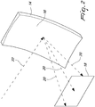
Fig. 2 is an illustration of a radar pulsed signal reflected of a reflector of the radar antenna ofFig. 1 to a predetermined far field radiation pattern; -
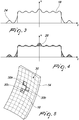
Fig. 3 is an illustration of comparing a radiation pattern with the predetermined far field radiation pattern ofFig. 2 ; -
Fig. 4 is an illustration of restricting the radiation patter to form a constrained radiation pattern; and -
Fig. 5 is an illustration of a matrix of a variance in the level of the reflective surface at various points. - This disclosure generally relates to a
radar antenna 10. With reference toFig. 1 , theradar antenna 10 may comprise afeeder 12 for delivering a radar signal to areflector 14. The radar signal may be a radar pulse signal or a Frequency Modulated Continuous Wave (FMCW). Thereflector 14 may have areflective surface 16 that is illuminated by thefeeder 12. The radar signal may be reflected towards a zone of surveillance by thereflective surface 16. - The
feeder 12 may be offset from the center point of thereflective surface 16. Thereflective surface 16 may determine the required radiation pattern of theradar antenna 10. Thereflector 14 may be machined so as to have a variance across thereflective surface 16. Thereflector 14 may be machined so as to have a variance in the levelreflective surface 16. The variance in the level of thereflective surface 16 may be defined as the change in the depth/ height of thereflective surface 16. The variance in the level of thereflective surface 16 may determine the shape of the radiation pattern. - The
reflector 14 may be a parabolic reflector. Thereflector 14 may collimate radiation in a single plane.Reflector 14 may allow for beam-steering or beam-shaping of an inspection beam with predetermined elevation or azimuth beam angles. - A method to manufacture the
reflector 14 for theradar antenna 10 is described. With reference toFig. 2 , theradar antenna 10 may have a predetermined farfield radiation pattern 18 for a preset frequency range. The predetermined farfield radiation pattern 18 may be an ideal radiation pattern for a fixed antenna position and a radar inspection of a circular sector. The predetermined farfield radiation pattern 18 may have a wide frequency band. - The far
field radiation pattern 18 may depend on the amplitude and phase of thereflected radar signal 20 reflected from thereflective surface 16. The amplitude of thereflected radar signal 20 may be unchanged relative to the radar signal 22 delivered from thefeeder 12. The phase of the reflectedradar signal 20 may be modified by thereflective surface 16. In particular, the variance in the level of thereflective surface 16 may determine the phase of the reflectedradar signal 20. - The method may comprise the step a) of calculating a shape of the
reflective surface 16 based geometrical optics. The calculation of the shape is performed with reference to the predetermined farfield radiation pattern 18 for the preset frequency range. The preset frequency range is in the 10-100GHz range. At this preset frequency range the most benefit is achieved at the millimetre waves. The calculation of the shape may be achieved, as examples, by Matlab or Comsol applied initially on a parabolic reflector. - The method comprises the step b) of determining initial radiation current on the
reflective surface 16 for the calculated shape. The initial radiation current for the calculated shape may be calculated using physical optics (PO). The initial radiation current may be calculated on thereflective surface 16. The far field radiation integral may be calculated on a hemispherical solid angle. The calculation of the initial radiation pattern may be achieved, as examples, by Matlab, Comsol of HFSS. - The method comprises the step c) of calculating the radiation pattern of the calculated shape of the
reflective surface 16 from the initial radiation current. The radiation pattern may be calculated by reversing the Helmholtz equation, that re-calculates the source currents based on the far field radiation. This calculation is known as "holographic inversion". - With reference to
Fig. 3 , the method comprises the step d) of comparing theradiation pattern 24 with the predetermined farfield radiation pattern 18 to obtain aconstrained radiation pattern 26 as seen inFig. 4 . The shaded portions reflect the restrictions that are placed on theradiation pattern 24 to obtain theconstrained radiation pattern 26. InFigs. 3 and 4 , the predetermined farfield radiation pattern 18 and theradiation pattern 24 are shown in relation to the Gain/ Directivity in the X-axis and the azimuth angle. - The
constrained radiation pattern 26 may be defined by restricting the amplitude of theradiation pattern 24 to the amplitude of the predetermined farfield radiation pattern 18. The radiation pattern located within the predetermined far field radiation pattern is unchanged. - The amplitude of the main lobe and side lobes of the
radiation pattern 24 may be restricted to the respective amplitudes of the predetermined farfield radiation pattern 18. The constrainedradiation pattern 26 may have amplitudes that are lower than the amplitudes of theradiation pattern 24. The admitted side lobe level of theradiation pattern 24 is restricted to the limit of the predetermined farfield radiation pattern 18. The constrainedradiation pattern 26 may have side lobes with reduced than the side lobe amplitudes of theradiation pattern 24. - The method comprises the step e) of calculating a constrained radiation current on the
reflector surface 18 corresponding to the constrainedradiation pattern 26. The constrained radiation current may be calculated based on PO with reference to the constrainedradiation pattern 26. The constrained radiation current may be calculated by holographic inversion of the far field radiation integral. The calculation of the constrained radiation current may be achieved, as examples, by Matlab. - The method comprises the step f) of determining a phase difference between the initial radiation current and the constrained radiation current for each point of the
reflective surface 16. Each point thereflective surface 16 may be defined by a x,y coordinate thereon. Each point may be defined by a pitch of lambda/20 where lambda is the wavelength associated to the centre frequency. The centre frequency may be that of the radar signal from the feeder or of the reflected radar signal. - The method comprises the step g) of varying the level of each point of the
reflective surface 16 to compensate the phase difference in order to obtain amatrix 30 defining an adjusted shape of thereflective surface 16 as seen inFig. 5 . The phase difference may be converted as a variation to the shape of thereflective surface 16. The phase difference may be converted as a variation for each point on thereflective surface 16. The phase difference may be compensated varying the distance between thereflective surface 16 and thefeeder 12 at each point thereon. - As an
example matrix 30 illustrates loweredpoints points reflective surface 16. Together these points show the adjusted shape of thereflective surface 16. - The method comprises the step h) of applying the
matrix 30 to machine thereflective surface 16. Thereflector 14 may be made from aluminium permitting machining of thereflective surface 16 to be performed with ease. The matrix serves as a template for the machining process. - In an embodiment, steps b) to f) are repeated to obtain the
matrix 30 prior to step g). The method may comprise a plurality of iterations involving steps b) to f). With each iteration the phase difference between the initial radiation current and the constrained radiation current is reduced and the modified shape shifts closer to the predetermined far field radiation pattern. Each iteration of steps b) to f) may lead to amatrix 30 at step g) that reflects a modified shape of thereflective surface 16. The number of iterations may be dependent on the level of phase difference to be achieved. - A
reflector 14 for aradar antenna 10 having a predetermined far field radiation pattern for a preset frequency range that is manufactured according to the foregoing method. - The skilled person would appreciate that foregoing embodiments may be modified or combined to obtain the
radar antenna 10 of the present disclosure. - This disclosure describes a
radar antenna 10. Theradar antenna 10 is capable of inspection of a surveillance area with specific azimuth and elevation beam angles. The azimuth beam angle may be between 12° to 30°. Preferably, the fixed azimuth beam angle is 12°, 22° or 30°. The elevation beam angle may be 2° to 5° to avoid ground reflections. Preferably the elevation beam angle is 2.5°. The inspection angle of theradar antenna 10 may be the combined azimuth and elevation beam angles. -
Radar antenna 10 may propagate a beam in the millimeter-wave region. In particular, the beam may have a frequency of 75GHz. All these mentioned methods are hardly producible at these frequencies and most of them do not have enough bandwidth like needed here (>1GHz).Radar antenna 10 may be configured to have a very low detection from outside of the desired inspection angle. In an embodiment, the inspection angle may comprise a 30° azimuth angle and a 2.5° elevation angle. This characteristic, named as roll-off, has to be a rejection of more than 20dB (from main gain) in less than 3° out of the (inspection angle).
Claims (8)
- A method to manufacture a reflector (14) for a radar antenna (10) having a predetermined far field radiation pattern (18) for a preset frequency range, the method comprising the steps of:a. calculating a shape of a reflective surface (16) based on geometrical optics with reference to the predetermined far field radiation pattern for the preset frequency range;b. determining initial radiation current on the reflective surface (16) for the calculated shape based on physical optics;c. calculating the radiation pattern (24) of the calculated shape of the reflective surface (16) from the initial radiation current;d. comparing the radiation pattern (24) with the predetermined far field radiation pattern (18) to obtain a constrained radiation pattern (26);e. calculating a constrained radiation current on the reflective surface (16) corresponding to the constrained radiation pattern (26);f. determining a phase difference between the initial radiation current and the constrained radiation current for each point of the reflective surface (16);g. varying the level of each point of the reflective surface (16) to compensate the phase difference so as to obtain a matrix (30) defining an adjusted shape of the reflective surface (16); andh. applying the matrix (30) to machine the reflective surface (16).
- The method of claim 1 wherein the constrained radiation pattern (26) is defined by restricting the amplitude of the radiation pattern (24) to the amplitude of the predetermined far field radiation pattern (18).
- The method of claim 2 wherein the amplitude of the main lobe and side lobes of the radiation pattern (24) are restricted to the respective amplitudes of the predetermined far field radiation pattern (18).
- The method of any one of preceding claims wherein a far field radiation integral is calculated on a hemispherical solid angle.
- The method of claim 4 wherein the constrained radiation current may be calculated by holographic inversion of the far field radiation integral.
- The method of any one of preceding claims wherein steps b) to f) are repeated to obtain the matrix (30) prior to step g).
- The method of any one of preceding claims wherein in step c the calculation is performed by reversing the Helmholtz equation.
- A reflector for a radar antenna (10) having a predetermined far field radiation pattern (18) for a preset frequency range manufactured according to the method of any one of the preceding claims.
Priority Applications (1)
| Application Number | Priority Date | Filing Date | Title |
|---|---|---|---|
| EP16177483.1A EP3264529B1 (en) | 2016-07-01 | 2016-07-01 | Reflector for a fixed position radar antenna |
Applications Claiming Priority (1)
| Application Number | Priority Date | Filing Date | Title |
|---|---|---|---|
| EP16177483.1A EP3264529B1 (en) | 2016-07-01 | 2016-07-01 | Reflector for a fixed position radar antenna |
Publications (2)
| Publication Number | Publication Date |
|---|---|
| EP3264529A1 EP3264529A1 (en) | 2018-01-03 |
| EP3264529B1 true EP3264529B1 (en) | 2019-04-17 |
Family
ID=56292585
Family Applications (1)
| Application Number | Title | Priority Date | Filing Date |
|---|---|---|---|
| EP16177483.1A Active EP3264529B1 (en) | 2016-07-01 | 2016-07-01 | Reflector for a fixed position radar antenna |
Country Status (1)
| Country | Link |
|---|---|
| EP (1) | EP3264529B1 (en) |
Families Citing this family (1)
| Publication number | Priority date | Publication date | Assignee | Title |
|---|---|---|---|---|
| CN114545347A (en) * | 2022-02-17 | 2022-05-27 | 南京理工大学 | Vehicle-mounted millimeter wave radar calibration system and method |
Family Cites Families (1)
| Publication number | Priority date | Publication date | Assignee | Title |
|---|---|---|---|---|
| US4750002A (en) * | 1986-09-12 | 1988-06-07 | Harris Corporation | Antenna panel having adjustable supports to improve surface accuracy |
-
2016
- 2016-07-01 EP EP16177483.1A patent/EP3264529B1/en active Active
Non-Patent Citations (1)
| Title |
|---|
| None * |
Also Published As
| Publication number | Publication date |
|---|---|
| EP3264529A1 (en) | 2018-01-03 |
Similar Documents
| Publication | Publication Date | Title |
|---|---|---|
| CN105789877B (en) | Four wave beam micro-strips transmission array antenna and its design method based on super surface | |
| CN107046182B (en) | Curved sensing array for improved angular resolution | |
| US8427362B2 (en) | Radar apparatus for radiating and receiving electric waves having grating lobes | |
| US9329265B2 (en) | Multiple transmission methods for improving the operation of automotive radar systems | |
| KR20180122349A (en) | Polarization measurement phased array radar system and its operation method | |
| US20160047907A1 (en) | Modular Planar Multi-Sector 90 Degrees FOV Radar Antenna Architecture | |
| CN106772305A (en) | The Targets Dots fusion method of centralized MIMO radar under a kind of nonopiate waveform | |
| CN110190409B (en) | Beam forming algorithm and design method of beam forming antenna and beam forming antenna | |
| CN210074171U (en) | Multi-beam shaped antenna | |
| EP3264529A1 (en) | Reflector for a fixed position radar antenna | |
| RU2674007C1 (en) | Located at big elevation angles radar targets elevation angle measuring method | |
| CN120314865A (en) | A neural network angle measurement method for beam waveguide reflector antenna | |
| Dubovitskiy | Practical design considerations for sparse antenna array using reflector antenna with continuously adjustable phase center displacement | |
| RU2677496C1 (en) | Ultra-high frequencies antenna array with variable geometry slots | |
| RU2457589C1 (en) | Phase method of nulling beam pattern of planar phased antenna array | |
| CN111478030B (en) | A reconfigurable sum-difference beamforming system and method | |
| Ram et al. | Craziness particle swarm optimization based hyper beamforming of linear antenna arrays | |
| RU2392703C1 (en) | Scanning hybrid antenna | |
| RU2573715C1 (en) | Method of forming beam pattern of double-ring digital phased antenna array | |
| RU2579610C2 (en) | Phase method of nulling beam pattern of planar phased antenna array | |
| JP2021085859A (en) | Millimeter wave sensor mounting structure | |
| RU2541871C2 (en) | Ultra-wideband multi-beam mirror antenna | |
| JP2005121421A (en) | Marine RCS measurement system | |
| CN115932850B (en) | A method of inverse synthetic aperture imaging based on frequency diversity array | |
| CN120979505B (en) | Beam generation method and device and electronic equipment |
Legal Events
| Date | Code | Title | Description |
|---|---|---|---|
| PUAI | Public reference made under article 153(3) epc to a published international application that has entered the european phase |
Free format text: ORIGINAL CODE: 0009012 |
|
| STAA | Information on the status of an ep patent application or granted ep patent |
Free format text: STATUS: THE APPLICATION HAS BEEN PUBLISHED |
|
| AK | Designated contracting states |
Kind code of ref document: A1 Designated state(s): AL AT BE BG CH CY CZ DE DK EE ES FI FR GB GR HR HU IE IS IT LI LT LU LV MC MK MT NL NO PL PT RO RS SE SI SK SM TR |
|
| AX | Request for extension of the european patent |
Extension state: BA ME |
|
| STAA | Information on the status of an ep patent application or granted ep patent |
Free format text: STATUS: REQUEST FOR EXAMINATION WAS MADE |
|
| 17P | Request for examination filed |
Effective date: 20180628 |
|
| RBV | Designated contracting states (corrected) |
Designated state(s): AL AT BE BG CH CY CZ DE DK EE ES FI FR GB GR HR HU IE IS IT LI LT LU LV MC MK MT NL NO PL PT RO RS SE SI SK SM TR |
|
| RIC1 | Information provided on ipc code assigned before grant |
Ipc: H01Q 15/16 20060101ALI20180817BHEP Ipc: H01Q 19/02 20060101ALI20180817BHEP Ipc: H01Q 15/14 20060101AFI20180817BHEP Ipc: H01Q 19/12 20060101ALI20180817BHEP Ipc: H01Q 19/13 20060101ALI20180817BHEP |
|
| GRAP | Despatch of communication of intention to grant a patent |
Free format text: ORIGINAL CODE: EPIDOSNIGR1 |
|
| STAA | Information on the status of an ep patent application or granted ep patent |
Free format text: STATUS: GRANT OF PATENT IS INTENDED |
|
| INTG | Intention to grant announced |
Effective date: 20181004 |
|
| GRAS | Grant fee paid |
Free format text: ORIGINAL CODE: EPIDOSNIGR3 |
|
| GRAA | (expected) grant |
Free format text: ORIGINAL CODE: 0009210 |
|
| STAA | Information on the status of an ep patent application or granted ep patent |
Free format text: STATUS: THE PATENT HAS BEEN GRANTED |
|
| AK | Designated contracting states |
Kind code of ref document: B1 Designated state(s): AL AT BE BG CH CY CZ DE DK EE ES FI FR GB GR HR HU IE IS IT LI LT LU LV MC MK MT NL NO PL PT RO RS SE SI SK SM TR |
|
| REG | Reference to a national code |
Ref country code: GB Ref legal event code: FG4D |
|
| REG | Reference to a national code |
Ref country code: CH Ref legal event code: EP |
|
| REG | Reference to a national code |
Ref country code: DE Ref legal event code: R096 Ref document number: 602016012452 Country of ref document: DE |
|
| REG | Reference to a national code |
Ref country code: AT Ref legal event code: REF Ref document number: 1122589 Country of ref document: AT Kind code of ref document: T Effective date: 20190515 Ref country code: IE Ref legal event code: FG4D |
|
| REG | Reference to a national code |
Ref country code: NL Ref legal event code: MP Effective date: 20190417 |
|
| REG | Reference to a national code |
Ref country code: LT Ref legal event code: MG4D |
|
| PG25 | Lapsed in a contracting state [announced via postgrant information from national office to epo] |
Ref country code: NL Free format text: LAPSE BECAUSE OF FAILURE TO SUBMIT A TRANSLATION OF THE DESCRIPTION OR TO PAY THE FEE WITHIN THE PRESCRIBED TIME-LIMIT Effective date: 20190417 |
|
| PG25 | Lapsed in a contracting state [announced via postgrant information from national office to epo] |
Ref country code: HR Free format text: LAPSE BECAUSE OF FAILURE TO SUBMIT A TRANSLATION OF THE DESCRIPTION OR TO PAY THE FEE WITHIN THE PRESCRIBED TIME-LIMIT Effective date: 20190417 Ref country code: LT Free format text: LAPSE BECAUSE OF FAILURE TO SUBMIT A TRANSLATION OF THE DESCRIPTION OR TO PAY THE FEE WITHIN THE PRESCRIBED TIME-LIMIT Effective date: 20190417 Ref country code: PT Free format text: LAPSE BECAUSE OF FAILURE TO SUBMIT A TRANSLATION OF THE DESCRIPTION OR TO PAY THE FEE WITHIN THE PRESCRIBED TIME-LIMIT Effective date: 20190817 Ref country code: SE Free format text: LAPSE BECAUSE OF FAILURE TO SUBMIT A TRANSLATION OF THE DESCRIPTION OR TO PAY THE FEE WITHIN THE PRESCRIBED TIME-LIMIT Effective date: 20190417 Ref country code: FI Free format text: LAPSE BECAUSE OF FAILURE TO SUBMIT A TRANSLATION OF THE DESCRIPTION OR TO PAY THE FEE WITHIN THE PRESCRIBED TIME-LIMIT Effective date: 20190417 Ref country code: AL Free format text: LAPSE BECAUSE OF FAILURE TO SUBMIT A TRANSLATION OF THE DESCRIPTION OR TO PAY THE FEE WITHIN THE PRESCRIBED TIME-LIMIT Effective date: 20190417 Ref country code: NO Free format text: LAPSE BECAUSE OF FAILURE TO SUBMIT A TRANSLATION OF THE DESCRIPTION OR TO PAY THE FEE WITHIN THE PRESCRIBED TIME-LIMIT Effective date: 20190717 Ref country code: ES Free format text: LAPSE BECAUSE OF FAILURE TO SUBMIT A TRANSLATION OF THE DESCRIPTION OR TO PAY THE FEE WITHIN THE PRESCRIBED TIME-LIMIT Effective date: 20190417 |
|
| PG25 | Lapsed in a contracting state [announced via postgrant information from national office to epo] |
Ref country code: BG Free format text: LAPSE BECAUSE OF FAILURE TO SUBMIT A TRANSLATION OF THE DESCRIPTION OR TO PAY THE FEE WITHIN THE PRESCRIBED TIME-LIMIT Effective date: 20190717 Ref country code: GR Free format text: LAPSE BECAUSE OF FAILURE TO SUBMIT A TRANSLATION OF THE DESCRIPTION OR TO PAY THE FEE WITHIN THE PRESCRIBED TIME-LIMIT Effective date: 20190718 Ref country code: PL Free format text: LAPSE BECAUSE OF FAILURE TO SUBMIT A TRANSLATION OF THE DESCRIPTION OR TO PAY THE FEE WITHIN THE PRESCRIBED TIME-LIMIT Effective date: 20190417 Ref country code: RS Free format text: LAPSE BECAUSE OF FAILURE TO SUBMIT A TRANSLATION OF THE DESCRIPTION OR TO PAY THE FEE WITHIN THE PRESCRIBED TIME-LIMIT Effective date: 20190417 Ref country code: LV Free format text: LAPSE BECAUSE OF FAILURE TO SUBMIT A TRANSLATION OF THE DESCRIPTION OR TO PAY THE FEE WITHIN THE PRESCRIBED TIME-LIMIT Effective date: 20190417 |
|
| REG | Reference to a national code |
Ref country code: AT Ref legal event code: MK05 Ref document number: 1122589 Country of ref document: AT Kind code of ref document: T Effective date: 20190417 |
|
| PG25 | Lapsed in a contracting state [announced via postgrant information from national office to epo] |
Ref country code: IS Free format text: LAPSE BECAUSE OF FAILURE TO SUBMIT A TRANSLATION OF THE DESCRIPTION OR TO PAY THE FEE WITHIN THE PRESCRIBED TIME-LIMIT Effective date: 20190817 |
|
| REG | Reference to a national code |
Ref country code: DE Ref legal event code: R097 Ref document number: 602016012452 Country of ref document: DE |
|
| PG25 | Lapsed in a contracting state [announced via postgrant information from national office to epo] |
Ref country code: EE Free format text: LAPSE BECAUSE OF FAILURE TO SUBMIT A TRANSLATION OF THE DESCRIPTION OR TO PAY THE FEE WITHIN THE PRESCRIBED TIME-LIMIT Effective date: 20190417 Ref country code: DK Free format text: LAPSE BECAUSE OF FAILURE TO SUBMIT A TRANSLATION OF THE DESCRIPTION OR TO PAY THE FEE WITHIN THE PRESCRIBED TIME-LIMIT Effective date: 20190417 Ref country code: RO Free format text: LAPSE BECAUSE OF FAILURE TO SUBMIT A TRANSLATION OF THE DESCRIPTION OR TO PAY THE FEE WITHIN THE PRESCRIBED TIME-LIMIT Effective date: 20190417 Ref country code: AT Free format text: LAPSE BECAUSE OF FAILURE TO SUBMIT A TRANSLATION OF THE DESCRIPTION OR TO PAY THE FEE WITHIN THE PRESCRIBED TIME-LIMIT Effective date: 20190417 Ref country code: CZ Free format text: LAPSE BECAUSE OF FAILURE TO SUBMIT A TRANSLATION OF THE DESCRIPTION OR TO PAY THE FEE WITHIN THE PRESCRIBED TIME-LIMIT Effective date: 20190417 Ref country code: SK Free format text: LAPSE BECAUSE OF FAILURE TO SUBMIT A TRANSLATION OF THE DESCRIPTION OR TO PAY THE FEE WITHIN THE PRESCRIBED TIME-LIMIT Effective date: 20190417 |
|
| PLBE | No opposition filed within time limit |
Free format text: ORIGINAL CODE: 0009261 |
|
| STAA | Information on the status of an ep patent application or granted ep patent |
Free format text: STATUS: NO OPPOSITION FILED WITHIN TIME LIMIT |
|
| PG25 | Lapsed in a contracting state [announced via postgrant information from national office to epo] |
Ref country code: SM Free format text: LAPSE BECAUSE OF FAILURE TO SUBMIT A TRANSLATION OF THE DESCRIPTION OR TO PAY THE FEE WITHIN THE PRESCRIBED TIME-LIMIT Effective date: 20190417 Ref country code: MC Free format text: LAPSE BECAUSE OF FAILURE TO SUBMIT A TRANSLATION OF THE DESCRIPTION OR TO PAY THE FEE WITHIN THE PRESCRIBED TIME-LIMIT Effective date: 20190417 |
|
| REG | Reference to a national code |
Ref country code: CH Ref legal event code: PL |
|
| 26N | No opposition filed |
Effective date: 20200120 |
|
| PG25 | Lapsed in a contracting state [announced via postgrant information from national office to epo] |
Ref country code: TR Free format text: LAPSE BECAUSE OF FAILURE TO SUBMIT A TRANSLATION OF THE DESCRIPTION OR TO PAY THE FEE WITHIN THE PRESCRIBED TIME-LIMIT Effective date: 20190417 |
|
| REG | Reference to a national code |
Ref country code: BE Ref legal event code: MM Effective date: 20190731 |
|
| PG25 | Lapsed in a contracting state [announced via postgrant information from national office to epo] |
Ref country code: LI Free format text: LAPSE BECAUSE OF NON-PAYMENT OF DUE FEES Effective date: 20190731 Ref country code: LU Free format text: LAPSE BECAUSE OF NON-PAYMENT OF DUE FEES Effective date: 20190701 Ref country code: BE Free format text: LAPSE BECAUSE OF NON-PAYMENT OF DUE FEES Effective date: 20190731 Ref country code: SI Free format text: LAPSE BECAUSE OF FAILURE TO SUBMIT A TRANSLATION OF THE DESCRIPTION OR TO PAY THE FEE WITHIN THE PRESCRIBED TIME-LIMIT Effective date: 20190417 Ref country code: CH Free format text: LAPSE BECAUSE OF NON-PAYMENT OF DUE FEES Effective date: 20190731 |
|
| PG25 | Lapsed in a contracting state [announced via postgrant information from national office to epo] |
Ref country code: FR Free format text: LAPSE BECAUSE OF NON-PAYMENT OF DUE FEES Effective date: 20190731 |
|
| PG25 | Lapsed in a contracting state [announced via postgrant information from national office to epo] |
Ref country code: IE Free format text: LAPSE BECAUSE OF NON-PAYMENT OF DUE FEES Effective date: 20190701 |
|
| GBPC | Gb: european patent ceased through non-payment of renewal fee |
Effective date: 20200701 |
|
| PG25 | Lapsed in a contracting state [announced via postgrant information from national office to epo] |
Ref country code: GB Free format text: LAPSE BECAUSE OF NON-PAYMENT OF DUE FEES Effective date: 20200701 |
|
| PG25 | Lapsed in a contracting state [announced via postgrant information from national office to epo] |
Ref country code: CY Free format text: LAPSE BECAUSE OF FAILURE TO SUBMIT A TRANSLATION OF THE DESCRIPTION OR TO PAY THE FEE WITHIN THE PRESCRIBED TIME-LIMIT Effective date: 20190417 |
|
| PG25 | Lapsed in a contracting state [announced via postgrant information from national office to epo] |
Ref country code: MT Free format text: LAPSE BECAUSE OF FAILURE TO SUBMIT A TRANSLATION OF THE DESCRIPTION OR TO PAY THE FEE WITHIN THE PRESCRIBED TIME-LIMIT Effective date: 20190417 Ref country code: HU Free format text: LAPSE BECAUSE OF FAILURE TO SUBMIT A TRANSLATION OF THE DESCRIPTION OR TO PAY THE FEE WITHIN THE PRESCRIBED TIME-LIMIT; INVALID AB INITIO Effective date: 20160701 |
|
| PG25 | Lapsed in a contracting state [announced via postgrant information from national office to epo] |
Ref country code: MK Free format text: LAPSE BECAUSE OF FAILURE TO SUBMIT A TRANSLATION OF THE DESCRIPTION OR TO PAY THE FEE WITHIN THE PRESCRIBED TIME-LIMIT Effective date: 20190417 |
|
| P01 | Opt-out of the competence of the unified patent court (upc) registered |
Effective date: 20230517 |
|
| REG | Reference to a national code |
Ref country code: DE Ref legal event code: R082 Ref document number: 602016012452 Country of ref document: DE Ref country code: DE Ref legal event code: R081 Ref document number: 602016012452 Country of ref document: DE Owner name: PROGRESS RAIL SIGNALING S.P.A., SERRAVALLE PIS, IT Free format text: FORMER OWNER: PROGRESS RAIL INSPECTION & INFORMATION SYSTEMS S.R.L., BOLOGNA, IT |
|
| PGFP | Annual fee paid to national office [announced via postgrant information from national office to epo] |
Ref country code: DE Payment date: 20250620 Year of fee payment: 10 |
|
| PGFP | Annual fee paid to national office [announced via postgrant information from national office to epo] |
Ref country code: IT Payment date: 20250619 Year of fee payment: 10 |