EP3264257A1 - Image outputting method and apparatus, computer program and recording medium - Google Patents

Image outputting method and apparatus, computer program and recording medium Download PDF

Info

Publication number
EP3264257A1
EP3264257A1 EP17168846.8A EP17168846A EP3264257A1 EP 3264257 A1 EP3264257 A1 EP 3264257A1 EP 17168846 A EP17168846 A EP 17168846A EP 3264257 A1 EP3264257 A1 EP 3264257A1
Authority
EP
European Patent Office
Prior art keywords
target
target image
data
image
controlling
Prior art date
Legal status (The legal status is an assumption and is not a legal conclusion. Google has not performed a legal analysis and makes no representation as to the accuracy of the status listed.)
Ceased
Application number
EP17168846.8A
Other languages
German (de)
French (fr)
Inventor
Yi Ding
Deguo MENG
Enxing Hou
Current Assignee (The listed assignees may be inaccurate. Google has not performed a legal analysis and makes no representation or warranty as to the accuracy of the list.)
Beijing Xiaomi Mobile Software Co Ltd
Original Assignee
Beijing Xiaomi Mobile Software Co Ltd
Priority date (The priority date is an assumption and is not a legal conclusion. Google has not performed a legal analysis and makes no representation as to the accuracy of the date listed.)
Filing date
Publication date
Application filed by Beijing Xiaomi Mobile Software Co Ltd filed Critical Beijing Xiaomi Mobile Software Co Ltd
Publication of EP3264257A1 publication Critical patent/EP3264257A1/en
Ceased legal-status Critical Current

Links

Images

Classifications

    • HELECTRICITY
    • H04ELECTRIC COMMUNICATION TECHNIQUE
    • H04NPICTORIAL COMMUNICATION, e.g. TELEVISION
    • H04N7/00Television systems
    • H04N7/18Closed-circuit television [CCTV] systems, i.e. systems in which the video signal is not broadcast
    • GPHYSICS
    • G06COMPUTING OR CALCULATING; COUNTING
    • G06FELECTRIC DIGITAL DATA PROCESSING
    • G06F16/00Information retrieval; Database structures therefor; File system structures therefor
    • G06F16/50Information retrieval; Database structures therefor; File system structures therefor of still image data
    • G06F16/58Retrieval characterised by using metadata, e.g. metadata not derived from the content or metadata generated manually
    • G06F16/583Retrieval characterised by using metadata, e.g. metadata not derived from the content or metadata generated manually using metadata automatically derived from the content
    • GPHYSICS
    • G06COMPUTING OR CALCULATING; COUNTING
    • G06FELECTRIC DIGITAL DATA PROCESSING
    • G06F16/00Information retrieval; Database structures therefor; File system structures therefor
    • G06F16/70Information retrieval; Database structures therefor; File system structures therefor of video data
    • G06F16/78Retrieval characterised by using metadata, e.g. metadata not derived from the content or metadata generated manually
    • G06F16/783Retrieval characterised by using metadata, e.g. metadata not derived from the content or metadata generated manually using metadata automatically derived from the content
    • GPHYSICS
    • G06COMPUTING OR CALCULATING; COUNTING
    • G06FELECTRIC DIGITAL DATA PROCESSING
    • G06F3/00Input arrangements for transferring data to be processed into a form capable of being handled by the computer; Output arrangements for transferring data from processing unit to output unit, e.g. interface arrangements
    • G06F3/14Digital output to display device ; Cooperation and interconnection of the display device with other functional units
    • G06F3/147Digital output to display device ; Cooperation and interconnection of the display device with other functional units using display panels
    • GPHYSICS
    • G06COMPUTING OR CALCULATING; COUNTING
    • G06VIMAGE OR VIDEO RECOGNITION OR UNDERSTANDING
    • G06V20/00Scenes; Scene-specific elements
    • G06V20/40Scenes; Scene-specific elements in video content
    • G06V20/46Extracting features or characteristics from the video content, e.g. video fingerprints, representative shots or key frames
    • GPHYSICS
    • G06COMPUTING OR CALCULATING; COUNTING
    • G06VIMAGE OR VIDEO RECOGNITION OR UNDERSTANDING
    • G06V20/00Scenes; Scene-specific elements
    • G06V20/50Context or environment of the image
    • G06V20/52Surveillance or monitoring of activities, e.g. for recognising suspicious objects
    • GPHYSICS
    • G08SIGNALLING
    • G08BSIGNALLING SYSTEMS, e.g. PERSONAL CALLING SYSTEMS; ORDER TELEGRAPHS; ALARM SYSTEMS
    • G08B13/00Burglar, theft or intruder alarms
    • G08B13/18Actuation by interference with heat, light, or radiation of shorter wavelength; Actuation by intruding sources of heat, light, or radiation of shorter wavelength
    • G08B13/189Actuation by interference with heat, light, or radiation of shorter wavelength; Actuation by intruding sources of heat, light, or radiation of shorter wavelength using passive radiation detection systems
    • G08B13/194Actuation by interference with heat, light, or radiation of shorter wavelength; Actuation by intruding sources of heat, light, or radiation of shorter wavelength using passive radiation detection systems using image scanning and comparing systems
    • G08B13/196Actuation by interference with heat, light, or radiation of shorter wavelength; Actuation by intruding sources of heat, light, or radiation of shorter wavelength using passive radiation detection systems using image scanning and comparing systems using television cameras
    • G08B13/19654Details concerning communication with a camera
    • G08B13/19656Network used to communicate with a camera, e.g. WAN, LAN, Internet
    • GPHYSICS
    • G08SIGNALLING
    • G08BSIGNALLING SYSTEMS, e.g. PERSONAL CALLING SYSTEMS; ORDER TELEGRAPHS; ALARM SYSTEMS
    • G08B13/00Burglar, theft or intruder alarms
    • G08B13/18Actuation by interference with heat, light, or radiation of shorter wavelength; Actuation by intruding sources of heat, light, or radiation of shorter wavelength
    • G08B13/189Actuation by interference with heat, light, or radiation of shorter wavelength; Actuation by intruding sources of heat, light, or radiation of shorter wavelength using passive radiation detection systems
    • G08B13/194Actuation by interference with heat, light, or radiation of shorter wavelength; Actuation by intruding sources of heat, light, or radiation of shorter wavelength using passive radiation detection systems using image scanning and comparing systems
    • G08B13/196Actuation by interference with heat, light, or radiation of shorter wavelength; Actuation by intruding sources of heat, light, or radiation of shorter wavelength using passive radiation detection systems using image scanning and comparing systems using television cameras
    • G08B13/19654Details concerning communication with a camera
    • G08B13/1966Wireless systems, other than telephone systems, used to communicate with a camera
    • HELECTRICITY
    • H04ELECTRIC COMMUNICATION TECHNIQUE
    • H04NPICTORIAL COMMUNICATION, e.g. TELEVISION
    • H04N7/00Television systems
    • H04N7/18Closed-circuit television [CCTV] systems, i.e. systems in which the video signal is not broadcast
    • H04N7/188Capturing isolated or intermittent images triggered by the occurrence of a predetermined event, e.g. an object reaching a predetermined position
    • GPHYSICS
    • G08SIGNALLING
    • G08BSIGNALLING SYSTEMS, e.g. PERSONAL CALLING SYSTEMS; ORDER TELEGRAPHS; ALARM SYSTEMS
    • G08B13/00Burglar, theft or intruder alarms
    • G08B13/18Actuation by interference with heat, light, or radiation of shorter wavelength; Actuation by intruding sources of heat, light, or radiation of shorter wavelength
    • G08B13/189Actuation by interference with heat, light, or radiation of shorter wavelength; Actuation by intruding sources of heat, light, or radiation of shorter wavelength using passive radiation detection systems
    • G08B13/194Actuation by interference with heat, light, or radiation of shorter wavelength; Actuation by intruding sources of heat, light, or radiation of shorter wavelength using passive radiation detection systems using image scanning and comparing systems
    • G08B13/196Actuation by interference with heat, light, or radiation of shorter wavelength; Actuation by intruding sources of heat, light, or radiation of shorter wavelength using passive radiation detection systems using image scanning and comparing systems using television cameras
    • G08B13/19602Image analysis to detect motion of the intruder, e.g. by frame subtraction
    • GPHYSICS
    • G08SIGNALLING
    • G08BSIGNALLING SYSTEMS, e.g. PERSONAL CALLING SYSTEMS; ORDER TELEGRAPHS; ALARM SYSTEMS
    • G08B17/00Fire alarms; Alarms responsive to explosion
    • G08B17/12Actuation by presence of radiation or particles, e.g. of infrared radiation or of ions
    • G08B17/125Actuation by presence of radiation or particles, e.g. of infrared radiation or of ions by using a video camera to detect fire or smoke
    • GPHYSICS
    • G09EDUCATION; CRYPTOGRAPHY; DISPLAY; ADVERTISING; SEALS
    • G09GARRANGEMENTS OR CIRCUITS FOR CONTROL OF INDICATING DEVICES USING STATIC MEANS TO PRESENT VARIABLE INFORMATION
    • G09G2320/00Control of display operating conditions
    • G09G2320/10Special adaptations of display systems for operation with variable images
    • G09G2320/103Detection of image changes, e.g. determination of an index representative of the image change

Definitions

  • the present invention relates to the technical field of electronics, and more particularly to an image outputting method and apparatus, a computer program and a recording medium.
  • Smart furniture and electrical appliances are more and more used in people's daily life and work, making people's life increasingly convenient.
  • smart cameras With the wide spread use of smart cameras, it is possible to remotely monitor the situation at home through smart cameras even when a user is not at home.
  • the user has to view monitoring records on his/her own initiative, in order to get knowledge of the situation in the home. If an emergency situation occurs in the home, the user cannot know it at once. Thus, the effective utilization of the smart cameras will be reduced.
  • the present invention provides an image outputting method and apparatus, a computer program and a recording medium.
  • an image outputting method comprises: acquiring data of frames collected by a target camera; acquiring a target image based on the data of frames; and controlling a target terminal to output an alert message which at least includes the target image.
  • controlling the target terminal to output the alert message comprises: controlling the target terminal to display the target image at a visible position.
  • controlling the target terminal to display the target image at the visible position includes one or more of the following: controlling the target terminal to switch to displaying the target image; controlling the target terminal to display the target image in a desktop background; controlling the target terminal to display the target image in a lock screen background; and controlling the target terminal to display the target image in a floating window.
  • acquiring the target image based on the data of frames comprises: acquiring a target image indicating an abnormal event based on the data of frames.
  • acquiring the target image indicating an abnormal event based on the data of frames comprises: acquiring similarity between data of adjacent frames among the data of frames; acquiring target images corresponding to the data of adjacent frames, if the similarity is smaller than a predetermined threshold value.
  • the abnormal event includes one or more of the following events: a stranger has entered a predetermined area; a location of an object in the predetermined area has changed; the predetermined area has been on fire.
  • an image outputting apparatus comprises: a first acquisition module configured to acquire data of frames collected by a target camera; a second acquisition module configured to acquire a target image based on the data of frames; and a controlling module configured to control a target terminal to output an alert message which at least includes the target image.
  • the controlling module comprises: a controlling sub-module configured to control the target terminal to display the target image at a visible position.
  • the second acquisition module comprises: a target image acquiring sub-module configured to acquire a target image indicating an abnormal event based on the data of frames.
  • the target image acquiring sub-module comprises: a first acquiring sub-module configured to acquire similarity between data of adjacent frames among the data of frames; and a second acquiring sub-module configured to acquire target images corresponding to the data of adjacent frames, if the similarity is smaller than a predetermined threshold value.
  • the abnormal event includes one or more of the following events: a stranger has entered a predetermined area; a location of an object in the predetermined area has changed; and the predetermined area has been on fire.
  • an image outputting apparatus comprises: a processor; and a memory storing instructions executable by the processor.
  • the processor is configured to: acquire data of frames collected by a target camera; acquire a target image based on the data of frames; and control a target terminal to output an alert message which at least includes the target image.
  • the steps of the image outputting method are determined by computer program instructions.
  • This program can use any programming language and take the form of source code, object code or a code intermediate between source code and object code, such as a partially compiled form, or any other desirable form.
  • the information medium can be an integrated circuit in which the program is incorporated, the circuit being adapted to execute the method in question or to be used in its execution.
  • data of frames collected by a target camera is acquired, a target image is acquired based on the data of frames, and a target terminal is controlled to output an alert message which at least includes the target image.
  • data of frames collected by a target camera is acquired, a target image indicating an abnormal event is acquired based on the data of frames, and a target terminal is controlled to display the target image at a visible position.
  • a target terminal is controlled to display the target image at a visible position.
  • first, second, third and so on may be used herein to describe various information, such information is not limited to these terms, which are only used to distinguish between different information of the same category.
  • first information can also be referred to as the second information, and similarly the second information can also be referred to as the first information, without departing from the scope of the present invention.
  • if as used herein can be interpreted as "when", “while”, or "in response to determining”.
  • Fig. 1 is a schematic diagram of an exemplary system architecture where embodiments of the present invention are applicable.
  • a system architecture 100 may include a camera device 101, a terminal device 102, a network 103, and a server 104.
  • the network 103 is used for providing a communication link medium between the camera device 101 or the terminal device 102 and the server 104.
  • the camera device 101 may be one of various devices with a photographing function, and may comprise one or more cameras configured to capture images and a processor configured to control the cameras.
  • the camera device 101 may interact with the server 104 via the network 103, so as to send collected data to the server 104 or receive control instructions sent by the server.
  • the terminal device 102 may also interact with the server 104 via the network 103, so as to receive or send a request or information etc.
  • the terminal device 102 may be one of a variety of electronic devices, including but not limited to mobile terminal devices such as smart phones, smart wearable devices, tablet PCs, Personal Digital Assistance (PDAs) and so on.
  • PDAs Personal Digital Assistance
  • the server 104 can provide smart monitoring and management services, as well as a variety of other services.
  • the server 104 can perform processing, such as storage and analysis, on the received data, and can also send information to the camera device 101 or the terminal device 102, etc.
  • the server 104 can receive the image data collected by the camera device 101, and analyze the received image data to determine whether an abnormal event has occurred in the area photographed by the camera device 101. If it is determined through analysis that there is an abnormal event in the area, it is possible to sort out the image data, acquire an abnormal image, and send the abnormal image to the terminal device 102 for viewing by the user.
  • a server can provide one or more services and that the same service can be provided by a number of servers.
  • Fig. 1 the number of camera devices, terminal devices, networks and servers in Fig. 1 is only illustrative. There may be any number of camera devices, terminal devices, networks and servers according to implementation requirements.
  • Fig. 2 is a flowchart illustrating an image outputting method according to an exemplary embodiment.
  • the method may be applied to a smart camera device or a server. As shown, the method comprises the following steps.
  • step 201 data of frames collected by a target camera is acquired.
  • image data of each frame collected by the target camera is acquired for analysis and processing.
  • the target camera is used to photograph a target monitored area.
  • the camera photographing the doorway area may be used as a target camera.
  • the target camera may be an electronic video camera taking video of the area being monitored, or an electronic or digital camera taking periodic photographic images of the area being monitored. In this way image data of a plurality of frames is generated.
  • a target image is acquired based on the data of frames.
  • the target image is an image that indicates or includes an abnormal event.
  • the target image may be an image in which a stranger entering the target monitored area is photographed, an image in which a change happening to an object in the target monitored area (e.g. a certain object in the target monitored area being blown down, or things hanging on a wall loosening and falling down etc.) is photographed, or an image in which the target monitored area being on fire is photographed, etc.
  • the target image may be some other form of alert message, and specific contents and forms of the target image are not limited in the present invention.
  • the image corresponding to the data of the frame may be determined and generated as a target image.
  • the target terminal after acquiring the target image, it is possible to first generate an alert message which at least includes the target image and then transfer the alert message to a target terminal, so that the target terminal can present the alert message to the user.
  • the target terminal is exactly the one used by the same user as the camera device acquiring the target image.
  • the target terminal may be a terminal having the same user account as the camera device, and may also be a terminal associated with the camera device, etc.

Landscapes

  • Engineering & Computer Science (AREA)
  • Theoretical Computer Science (AREA)
  • Physics & Mathematics (AREA)
  • General Physics & Mathematics (AREA)
  • Multimedia (AREA)
  • Library & Information Science (AREA)
  • General Engineering & Computer Science (AREA)
  • Data Mining & Analysis (AREA)
  • Databases & Information Systems (AREA)
  • Signal Processing (AREA)
  • Human Computer Interaction (AREA)
  • Computer Networks & Wireless Communication (AREA)
  • Business, Economics & Management (AREA)
  • Emergency Management (AREA)
  • Computer Vision & Pattern Recognition (AREA)
  • Alarm Systems (AREA)
  • User Interface Of Digital Computer (AREA)
  • Telephonic Communication Services (AREA)
  • Closed-Circuit Television Systems (AREA)
  • Two-Way Televisions, Distribution Of Moving Picture Or The Like (AREA)

Abstract

The present invention relates to an image outputting method and apparatus, a computer program and a recording medium. The method comprises: acquiring data of frames collected by a target camera; acquiring a target image based on the data of frames; and controlling a target terminal to output an alert message which at least includes the target image. With this embodiment, when an emergency situation occurs in a user's home, the user can be aware of it at once, thereby increasing the effective utilization of the smart camera device.

Description

    TECHNICAL FIELD
  • The present invention relates to the technical field of electronics, and more particularly to an image outputting method and apparatus, a computer program and a recording medium.
  • BACKGROUND
  • With the continuous development of the smart terminal technology, various smart furniture and electrical appliances emerge constantly. Smart furniture and electrical appliances are more and more used in people's daily life and work, making people's life increasingly convenient. With the wide spread use of smart cameras, it is possible to remotely monitor the situation at home through smart cameras even when a user is not at home. However, in the related art, the user has to view monitoring records on his/her own initiative, in order to get knowledge of the situation in the home. If an emergency situation occurs in the home, the user cannot know it at once. Thus, the effective utilization of the smart cameras will be reduced.
  • SUMMARY
  • In order to address the foregoing technical problems, the present invention provides an image outputting method and apparatus, a computer program and a recording medium.
  • According to a first aspect of the present invention, an image outputting method is provided. The method comprises: acquiring data of frames collected by a target camera; acquiring a target image based on the data of frames; and controlling a target terminal to output an alert message which at least includes the target image.
  • Optionally, controlling the target terminal to output the alert message comprises: controlling the target terminal to display the target image at a visible position.
  • Optionally, controlling the target terminal to display the target image at the visible position includes one or more of the following: controlling the target terminal to switch to displaying the target image; controlling the target terminal to display the target image in a desktop background; controlling the target terminal to display the target image in a lock screen background; and controlling the target terminal to display the target image in a floating window.
  • Optionally, acquiring the target image based on the data of frames comprises: acquiring a target image indicating an abnormal event based on the data of frames.
  • Optionally, acquiring the target image indicating an abnormal event based on the data of frames comprises: acquiring similarity between data of adjacent frames among the data of frames; acquiring target images corresponding to the data of adjacent frames, if the similarity is smaller than a predetermined threshold value.
  • Optionally, the abnormal event includes one or more of the following events: a stranger has entered a predetermined area; a location of an object in the predetermined area has changed; the predetermined area has been on fire.
  • According to a second aspect of the present invention, an image outputting apparatus is provided. The image outputting apparatus comprises: a first acquisition module configured to acquire data of frames collected by a target camera; a second acquisition module configured to acquire a target image based on the data of frames; and a controlling module configured to control a target terminal to output an alert message which at least includes the target image.
  • Optionally, the controlling module comprises: a controlling sub-module configured to control the target terminal to display the target image at a visible position.
  • Optionally, the controlling sub-module comprises one or more of the following: a first display controlling sub-module configured to control the target terminal to switch to displaying the target image; a second display controlling sub-module configured to control the target terminal to display the target image in a desktop background; a third display controlling sub-module configured to control the target terminal to display the target image in a lock screen background; and a fourth display controlling sub-module configured to control the target terminal to display the target image in a floating window.
  • Optionally, the second acquisition module comprises: a target image acquiring sub-module configured to acquire a target image indicating an abnormal event based on the data of frames.
  • Optionally, the target image acquiring sub-module comprises: a first acquiring sub-module configured to acquire similarity between data of adjacent frames among the data of frames; and a second acquiring sub-module configured to acquire target images corresponding to the data of adjacent frames, if the similarity is smaller than a predetermined threshold value.
  • Optionally, the abnormal event includes one or more of the following events: a stranger has entered a predetermined area; a location of an object in the predetermined area has changed; and the predetermined area has been on fire.
  • According to a third aspect of the present invention, an image outputting apparatus is provided. The image outputting apparatus comprises: a processor; and a memory storing instructions executable by the processor. The processor is configured to: acquire data of frames collected by a target camera; acquire a target image based on the data of frames; and control a target terminal to output an alert message which at least includes the target image.
  • In one particular embodiment, the steps of the image outputting method are determined by computer program instructions.
  • Consequently, according to a fourth aspect, the invention is also directed to a computer program for executing the steps of the image outputting method as described above when this program is executed by a computer.
  • This program can use any programming language and take the form of source code, object code or a code intermediate between source code and object code, such as a partially compiled form, or any other desirable form.
  • The invention is also directed to a computer-readable information medium containing instructions of a computer program as described above.
  • The information medium can be any entity or device capable of storing the program. For example, the support can include storage means such as a ROM, for example a CD ROM or a microelectronic circuit ROM, or magnetic storage means, for example a diskette (floppy disk) or a hard disk.
  • Alternatively, the information medium can be an integrated circuit in which the program is incorporated, the circuit being adapted to execute the method in question or to be used in its execution.
  • The technical solutions provided by embodiments of the present invention may have the following beneficial technical effects.
  • According to the image outputting methods provided by the above embodiments of the present invention, data of frames collected by a target camera is acquired, a target image is acquired based on the data of frames, and a target terminal is controlled to output an alert message which at least includes the target image. Thus, when an emergency situation occurs in a user's home, the user can be aware of it at once, thereby increasing the effective utilization of the smart camera.
  • According to an image outputting method provided by one of the above embodiments of the present invention, data of frames collected by a target camera is acquired, a target image indicating an abnormal event is acquired based on the data of frames, and a target terminal is controlled to display the target image at a visible position. Thus, without opening a monitoring image display interface, a user can view the target image more quickly (upon occurrence of an abnormal event in a target monitored area) to get knowledge of the abnormal event, thereby increasing the effective utilization of the smart camera.
  • It is to be understood that both the foregoing general description and the following detailed description are exemplary and explanatory only and are not restrictive of the invention.
  • BRIEF DESCRIPTION OF THE DRAWINGS
  • The accompanying drawings, which are incorporated in and constitute a part of this specification, illustrate embodiments consistent with the invention and, together with the description, serve to explain the principles of the invention.
    • Fig. 1 is a diagram illustrating an exemplary system architecture where embodiments of the present invention are applicable according to an exemplary embodiment of the present invention.
    • Fig. 2 is a flowchart illustrating an image outputting method according to an exemplary embodiment of the present invention.
    • Fig. 3 is a flowchart illustrating another image outputting method according to an exemplary embodiment of the present invention.
    • Fig. 4 is a block diagram illustrating an image outputting apparatus according to an exemplary embodiment of the present invention.
    • Fig. 5 is a block diagram illustrating another image outputting apparatus according to an exemplary embodiment of the present invention.
    • Fig. 6 is a block diagram illustrating yet another image outputting apparatus according to an exemplary embodiment of the present invention.
    • Fig. 7 is a block diagram illustrating still another image outputting apparatus according to an exemplary embodiment of the present invention.
    • Fig. 8 is a structure schematic diagram illustrating an image outputting apparatus according to an exemplary embodiment of the present invention.
    DETAILED DESCRIPTION
  • Reference will now be made in detail to certain exemplary embodiments, examples of which are illustrated in the accompanying drawings. The following description refers to the accompanying drawings in which the same numbers in different figures represent the same or similar elements unless otherwise indicated. The implementations set forth in the following description of embodiments do not represent all implementations consistent with the invention. Instead, they are merely examples of apparatuses and methods consistent with aspects related to the invention as recited in the appended claims.
  • The terms used herein are for the purpose of illustrating the embodiments only, rather than limiting the present invention. The terms "a", "said" and "the" of singular forms used in the present description and the attached claims are also intended to include their plural forms, unless otherwise clearly specified in the context. It can also be appreciated that the term "and/or" as used herein refers to any or all possible combinations of one or more associated items as listed.
  • It can be appreciated that, while the terms "first", "second", "third" and so on may be used herein to describe various information, such information is not limited to these terms, which are only used to distinguish between different information of the same category. For example, the first information can also be referred to as the second information, and similarly the second information can also be referred to as the first information, without departing from the scope of the present invention. Depending on the context, the term "if" as used herein can be interpreted as "when", "while", or "in response to determining".
  • Fig. 1 is a schematic diagram of an exemplary system architecture where embodiments of the present invention are applicable.
  • As shown in Fig. 1, a system architecture 100 may include a camera device 101, a terminal device 102, a network 103, and a server 104. The network 103 is used for providing a communication link medium between the camera device 101 or the terminal device 102 and the server 104.
  • The camera device 101 may be one of various devices with a photographing function, and may comprise one or more cameras configured to capture images and a processor configured to control the cameras. The camera device 101 may interact with the server 104 via the network 103, so as to send collected data to the server 104 or receive control instructions sent by the server. The terminal device 102 may also interact with the server 104 via the network 103, so as to receive or send a request or information etc. The terminal device 102 may be one of a variety of electronic devices, including but not limited to mobile terminal devices such as smart phones, smart wearable devices, tablet PCs, Personal Digital Assistance (PDAs) and so on.
  • The server 104 can provide smart monitoring and management services, as well as a variety of other services. The server 104 can perform processing, such as storage and analysis, on the received data, and can also send information to the camera device 101 or the terminal device 102, etc. For example, the server 104 can receive the image data collected by the camera device 101, and analyze the received image data to determine whether an abnormal event has occurred in the area photographed by the camera device 101. If it is determined through analysis that there is an abnormal event in the area, it is possible to sort out the image data, acquire an abnormal image, and send the abnormal image to the terminal device 102 for viewing by the user. It can be understood that a server can provide one or more services and that the same service can be provided by a number of servers.
  • It should be understood that the number of camera devices, terminal devices, networks and servers in Fig. 1 is only illustrative. There may be any number of camera devices, terminal devices, networks and servers according to implementation requirements.
  • In the following, the present invention will be described in detail in combination with specific embodiments.
  • Fig. 2 is a flowchart illustrating an image outputting method according to an exemplary embodiment. The method may be applied to a smart camera device or a server. As shown, the method comprises the following steps.
  • At step 201, data of frames collected by a target camera is acquired.
  • In this embodiment, first, image data of each frame collected by the target camera is acquired for analysis and processing. The target camera is used to photograph a target monitored area. For example, if a user wants to photograph a doorway area, the camera photographing the doorway area may be used as a target camera. In this context, the target camera may be an electronic video camera taking video of the area being monitored, or an electronic or digital camera taking periodic photographic images of the area being monitored. In this way image data of a plurality of frames is generated.
  • At step 202, a target image is acquired based on the data of frames.
  • In this embodiment, the target image is an image that indicates or includes an abnormal event. For example, the target image may be an image in which a stranger entering the target monitored area is photographed, an image in which a change happening to an object in the target monitored area (e.g. a certain object in the target monitored area being blown down, or things hanging on a wall loosening and falling down etc.) is photographed, or an image in which the target monitored area being on fire is photographed, etc. It could be understood that the target image may be some other form of alert message, and specific contents and forms of the target image are not limited in the present invention.
  • In this embodiment, it is possible to analyze the acquired image data of each frame, and to determine whether the image corresponding to the data of the frame includes an abnormal event. If an abnormal event is included, then the image corresponding to the data of the frame may be determined and generated as a target image.
  • At step 203, a target terminal is controlled to output an alert message, which at least includes the target image. The target terminal may be a smartphone or other computer device operated by the same user interested in monitoring the area with the target camera.
  • In this embodiment, after acquiring the target image, it is possible to first generate an alert message which at least includes the target image and then transfer the alert message to a target terminal, so that the target terminal can present the alert message to the user. The target terminal is exactly the one used by the same user as the camera device acquiring the target image. For example, the target terminal may be a terminal having the same user account as the camera device, and may also be a terminal associated with the camera device, etc.
  • In this embodiment, the alert message may also include voice information, which may for example alert a user to check monitoring records. It may also include alarm information, such as an audible alarm with a predetermined sound. The alert message may also include text alert information, which may be for example pushed to alert a user to check monitoring records. It could be understood that the alert message may include some other form of alert message, and specific contents and forms of the alert message are not limited in the present invention.
  • According to the image outputting method provided by the foregoing embodiment of the present invention, data of frames collected by a target camera is acquired, a target image is acquired based on the data of frames, and a target terminal is controlled to output an alert message which at least includes the target image. Thus, when an emergency situation occurs in a user's home, the user can get knowledge of it at once, thereby increasing the effective utilization of the smart camera device.
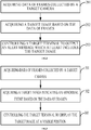
  • Fig. 3 is a flowchart illustrating another image outputting method according to an exemplary embodiment, wherein the process of acquiring a target image based on data of frames and controlling a target terminal to output an alert message is further detailed. The method may be applied to a smart camera device or a server. As shown, the method comprises the following steps.
  • At step 301, data of frames collected by a target camera is acquired.
  • At step 302, a target image indicating an abnormal event is acquired based on the data of frames.
  • In this embodiment, the abnormal event may include one or more of the following events: a stranger has entered a predetermined area; a location of an object in the predetermined area has changed; and the predetermined area has been on fire etc. It could be understood that the abnormal event may be some other event, and specific contents and forms of the abnormal event are not limited in the present invention. The predetermined area may be a target monitored area photographed by the target camera, and the choice of the predetermined area is not limited in the present invention.
  • In this embodiment, if no abnormal event occurs, there will be no change between images corresponding to data of adjacent frames. If an abnormal event occurs, multiple images corresponding to data of adjacent frames recording the abnormal event will differ. Accordingly, it is possible to determine whether acquired data of a frame corresponds to a target image indicating an abnormal event, based on whether the acquired data of the frame changes or not.
  • To be more specific, first, a measure of the similarity between the image data of every two adjacent frames among the data of frames is acquired one by one. This can be done by using any implementable algorithm, and the specific way of acquiring similarity between data of adjacent frames is not limited in the present invention. For example, running a correlation function comparing the image date in one frame to the next can be used to generate a value indicating correlation or similarity between the frames. Next, it is determined whether the individual similarity measures for the adjacent frames are smaller than a predetermined threshold value. The predetermined threshold value may be set in advance or may be an empirical value. It could be understood that the predetermined threshold value may be any reasonable value, and the specific amount of the predetermined threshold value is not limited in the present invention. If the similarity value between the data of adjacent frames is smaller than the predetermined threshold value, then the images corresponding to the data of the adjacent frames can be determined as target images indicating that a change in the environment has occurred which should be notified to the user at the target terminal.
  • At step 303, the target terminal is controlled to display the target image at a visible position.
  • In this embodiment, controlling the target terminal to display the target image at a visible position may be implemented as one of the following: controlling the target terminal to display each target image respectively at the visible position; controlling the target terminal to display some ones selected from the target images at the visible position; and controlling the target terminal to display a video or a dynamic image, which is generated based on the target images, at the visible position. It could be understood that the present invention is not limited in this regard.
  • Specifically, controlling the target terminal to display the target image at a visible position may include one or more of the following: controlling the target terminal to switch to displaying the target image; controlling the target terminal to display the target image in a desktop background; controlling the target terminal to display the target image in a lock screen background; and controlling the target terminal to display the target image in a floating window.
  • In this embodiment, controlling the target terminal to switch to displaying the target image may be implemented as controlling the target terminal to display target images in turn at the visible position. For example, supposing there are five target images, then the five target images may be displayed one by one at a visible position. Each target image may be displayed for a predetermined period (e.g., 5 seconds or 10 seconds etc.)
  • Controlling the target terminal to display the target image in a desktop background may be implemented as changing the desktop background of the target terminal to the target image. For example, after acquiring the target image, if the target terminal is displaying the desktop, then it may change the desktop background to the target image directly. In this way, a user can view the target image more quickly and conveniently, without opening a monitoring image display interface.
  • Controlling the target terminal to display the target image in a lock screen background may be implemented as changing the lock screen background of the target terminal to the target image. For example, after acquiring the target image, if the present target terminal is in a screen-sleep status, then it may directly light up the screen and change the screen lock background to the target image. In this way, a user can view the target image more quickly and conveniently, without opening a monitoring image display interface.
  • Controlling the target terminal to display the target image in a floating window may be implemented as displaying the target image in the floating window of the target terminal screen. For example, after acquiring the target image, if the present target terminal is being used by the user, then it may generate a small floating window on the currently displayed interface and display the target image in this floating window. In this way, the user can view the target image more quickly and conveniently, without opening the monitoring image display interface. In this context, a floating window, may be any new window opened and displayed on the terminal.
  • It could be understood that there can be other ways of displaying the target image. Specific ways of displaying the target image are not limited in the present invention.
  • It should be noted that the same steps as those in the embodiment of Fig. 2 will not be described redundantly in the embodiment of Fig. 3 any longer. Reference can be made to the embodiment of Fig. 2 for the same contents.
  • According to the image outputting method provided by the foregoing embodiment of the present invention, data of frames collected by a target camera is acquired, a target image indicating an abnormal event based on the data of frames is acquired, and the target terminal is controlled to display the target image at a visible position. Thus, without opening a monitoring image display interface, a user can view the target image more quickly (upon occurrence of an abnormal event in a target monitored area) to get knowledge of the abnormal event, thereby increasing the effective utilization of the smart camera device.
  • It should be noted that, although operations of the method of the present invention have been described in a specific order in the attached drawings, this does not require or imply that these operations must be performed in accordance with the specific order or that all operations must be performed in order to achieve desired results. On the contrary, the order for executing steps illustrated in the flowchart can change. Additionally or alternatively, it is possible to omit some steps, combine multiple steps into one step for implementation, and/or divide one step into multiple steps for implementation.
  • Correspondingly to the foregoing embodiments of image outputting methods, the present invention further provides embodiments of image outputting apparatuses.
  • Fig. 4 is a block diagram illustrating an image outputting apparatus according to an exemplary embodiment of the present invention. As shown, the apparatus comprises: a first acquisition module 401, a second acquisition module 402 and a controlling module 403.
  • The first acquisition module 401 is configured to acquire data of frames collected by a target camera.
  • The second acquisition module 402 is configured to acquire a target image based on data of frames acquired by the first acquisition module 401.
  • The controlling module 403 is configured to control a target terminal to output an alert message which at least includes the target image acquired by the second acquisition module 402.
  • According to the image outputting apparatus provided by the foregoing embodiment of the present invention, data of frames collected by a target camera is acquired, a target image is acquired based on the data of frames, and the target terminal is controlled to output an alert message which at least includes the target image. Thus, when an emergency situation occurs in a user's home, the user can be aware of it at once, thereby increasing the effective utilization of the smart camera device.
  • Fig. 5 is a block diagram illustrating another image outputting apparatus according to an exemplary embodiment of the present invention, which is on the basis of the above embodiment shown in Fig. 4. As shown, the controlling module 403 may comprise a controlling sub-module 501.
  • The controlling sub-module 501 is configured to control the target terminal to display the target image at a visible position.
  • In some optional embodiments, the controlling sub-module 501 may include one or more of a first display controlling sub-module, a second display controlling sub-module, a third display controlling sub-module and a fourth display controlling sub-module.
  • The first display controlling sub-module is configured to control the target terminal to switch to displaying the target image.
  • The second display controlling sub-module is configured to control the target terminal to display the target image in a desktop background.
  • The third display controlling sub-module is configured to control the target terminal to display the target image in a screen lock background.
  • The fourth display controlling sub-module is configured to control the target terminal to display the target image in the floating window.
  • Fig. 6 is a block diagram illustrating another image outputting apparatus according to an exemplary embodiment of the present invention, which is on the basis of the foregoing embodiment shown in Fig. 4. As shown, the second acquisition module 402 may comprise a target image acquiring sub-module 601.
  • The target image acquiring sub-module 601 is configured to acquire a target image indicating an abnormal event based on the foregoing data of frames.
  • According to the image outputting apparatus provided by the foregoing embodiment of the present invention, a target image indicating an abnormal event is acquired based on the data of frames, and the target terminal is controlled to output an alert message which at least includes the target image. Thus, when an emergency situation occurs in a user's home, the user can be aware of it at once, thereby increasing the effective utilization of the smart camera device.
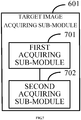
  • Fig. 7 is a block diagram illustrating another image outputting apparatus according to an exemplary embodiment of the present invention, which is on the basis of the foregoing embodiment shown in Fig. 6. As shown, the target image acquiring sub-module 601 may comprise a first acquiring sub-module 701 and a second acquiring sub-module 702.
  • The first acquiring sub-module 701 is configured to acquire similarity between data of adjacent frames among the data of frames.
  • The second acquiring sub-module 702 is configured to acquire target images corresponding to the data of adjacent frames, if the similarity acquired by the first acquiring sub-module 701 is smaller than a predetermined threshold value.
  • According to the image outputting apparatus provided by the foregoing embodiment of the present invention, similarity between data of adjacent frames among the data of frames is acquired; images corresponding to the data of adjacent frames are acquired as target images, if the similarity is smaller than a predetermined threshold value; and the target terminal is controlled to output an alert message which at least includes the target images. Thus, when an emergency situation occurs in a user's home, the user can be aware of it at once, thereby increasing the effective utilization of the smart camera device.
  • In some optional embodiments, the abnormal event may include one or more of the following events: a stranger has entered a predetermined area; a location of an object in the predetermined area has changed; and the predetermined area has been on fire.
  • It should be understood that, the above apparatus may be set in advance in a smart camera device or in a server, and may also be loaded into the smart camera device or the server through downloading etc. Respective modules in the apparatus can cooperate with units in the smart camera device or the server to implement the image outputting solutions.
  • For the apparatus embodiment, reference can be made to the corresponding description of the method embodiment since it substantially corresponds to the method embodiment. The apparatus embodiment as described above is illustrative only. Those units described as discrete components may or may not be physically separated. Those components shown as units may or may not be physical units, i.e., they can either be co-located, or distributed over a number of network elements. Some or all of the modules can be selected as desired to achieve the object of the present invention, as can be understood and implemented by those skilled in the art without any inventive efforts.
  • Correspondingly, the present invention further provides an image outputting apparatus. The image outputting apparatus comprises a processor; and a memory storing instructions executable by the processor. The processor is configured to acquire data of frames collected by a target camera, acquire a target image based on the data of frames and control a target terminal to output an alert message which at least includes the target image.
  • Fig. 8 is a structure schematic diagram illustrating an image outputting apparatus 9900 according to an exemplary embodiment. For example, the apparatus 9900 may be a mobile phone, a computer, a digital broadcast terminal, a messaging device, a gaming console, a tablet, a medical device, exercise equipment, a personal digital assistant or the like.
  • Referring to Fig. 8, the apparatus 9900 may include one or more of the following components: a processing component 9902, a memory 9904, a power component 9906, a multimedia component 9908, an audio component 9910, an input/output (I/O) interface 9912, a sensor component 9914 and a communication component 9916.
  • The processing component 9902 generally controls the overall operations of the apparatus 9900, for example, display, phone call, data communication, camera operation and recording operation. The processing component 9902 may include one or more processors 9920 to execute instructions to perform all or part of the steps in the above described methods. In addition, the processing component 9902 may include one or more modules to facilitate the interaction between the processing component 9902 and other components. For example, the processing component 9902 may include a multimedia module to facilitate the interaction between the processing component 9908 and the processing component 9902.
  • The memory 9904 is configured to store various types of data to support the operation performed on the apparatus 9900. Examples of such data include instructions for any applications or methods operated on the apparatus 9900, contact data, phonebook data, messages, pictures, video, etc. The memory 9904 may be implemented using any type of volatile or non-volatile memory devices, or a combination thereof, such as a static random access memory (SRAM), an electrically erasable programmable read-only memory (EEPROM), an erasable programmable read-only memory (EPROM), a programmable read-only memory (PROM), a read-only memory (ROM), a magnetic memory, a flash memory, a magnetic or optical disk.
  • The power component 9906 provides power to various components of the apparatus 9900. The power component 9906 may include a power supply management system, one or more power sources, and any other components associated with the generation, management, and distribution of power in the apparatus 9900.
  • The multimedia component 9908 includes a screen providing an output interface between the apparatus 9900 and the user. In some embodiments, the screen may include a Liquid Crystal Display (LCD) and a Touch Panel (TP). If the screen includes the touch panel, the screen may be implemented as a touch screen to receive input signals from the user. The touch panel includes one or more touch sensors to sense touches, swipes, and gestures on the touch panel. The touch sensors may not only sense a boundary of a touch or swipe action, but also sense a period of time and a pressure associated with the touch or swipe action. In some embodiments, the multimedia component 9908 includes a front camera and/or a rear camera. The front camera and the rear camera may receive external multimedia data while the apparatus 9900 is in an operation mode, such as a photographing mode or a video mode. Each of the front camera and the rear camera may be a fixed optical lens system or have focus and optical zoom capability.
  • The audio component 9910 is configured to output and/or input audio signals. For example, the audio component 9910 includes a microphone ("MIC") configured to receive an external audio signal when the apparatus 9900 is in an operation mode, such as a call mode, a recording mode, and a voice recognition mode. The received audio signal may be further stored in the memory 9904 or transmitted via the communication component 9916. In some embodiments, the audio component 9910 further includes a speaker to output audio signals.
  • The I/O interface 9912 provides an interface between the processing component 9902 and peripheral interface modules, such as a keyboard, a click wheel, buttons, and the like. The buttons may include, but are not limited to, a home button, a volume button, a starting button, and a locking button.
  • The sensor component 9914 includes one or more sensors to provide status assessments of various aspects of the apparatus 9900. For instance, the sensor component 9914 may detect an open/closed status of the apparatus 9900, relative positioning of components, e.g., the display and the keypad, of the apparatus 9900, a change in position of the apparatus 9900 or a component of the apparatus 9900, a presence or absence of user contact with the apparatus 9900, an orientation or an acceleration/deceleration of the apparatus 9900, and a change in temperature of the apparatus 9900. The sensor component 9914 may include a proximity sensor configured to detect the presence of nearby objects without any physical contact. The sensor component 9914 may also include a light sensor, such as a CMOS or CCD image sensor, for use in imaging applications. In some embodiments, the sensor component 9914 may also include an accelerometer sensor, a gyroscope sensor, a magnetic sensor, a pressure sensor, a microwave sensor or a temperature sensor.
  • The communication component 9916 is configured to facilitate wired or wireless communication between the apparatus 9900 and other devices. The apparatus 9900 can access a wireless network based on a communication standard, such as WiFi, 2G, or 3G, or a combination thereof. In one exemplary embodiment, the communication component 9916 receives a broadcast signal or broadcast related information from an external broadcast management system via a broadcast channel. In one exemplary embodiment, the communication component 9916 further includes a near field communication (NFC) module to facilitate short-range communications. For example, the NFC module may be implemented based on a radio frequency identification (RFID) technology, an infrared data association (IrDA) technology, an ultra-wideband (UWB) technology, a Bluetooth (BT) technology, and other technologies.
  • In exemplary embodiments, the apparatus 9900 may be implemented with one or more application specific integrated circuits (ASIC), digital signal processors (DSP), digital signal processing devices (DSPD), programmable logic devices (PLD), field programmable gate arrays (FPGA), controllers, micro-controllers, microprocessors, or other electronic components, for performing the above described methods.
  • In exemplary embodiments, there is also provided a non-transitory computer-readable storage medium including instructions, such as included in the memory 9904, executable by the processor 9920 of the apparatus 9900, for performing the above-described methods. For example, the non-transitory computer-readable storage medium may be a ROM, a RAM, a CD-ROM, a magnetic tape, a floppy disc, an optical data storage device, and the like.
  • Other embodiments of the invention will be apparent to those skilled in the art from consideration of the specification and practice of the invention disclosed here. This application is intended to cover any variations, uses, or adaptations of the invention following the general principles thereof and including such departures from the present disclosure as come within known or customary practice in the art. It is intended that the specification and examples be considered as exemplary only, with a true scope of the invention being indicated by the appended claims.
  • It will be appreciated that the present invention is not limited to the exact construction that has been described above and illustrated in the accompanying drawings, and that various modifications and changes can be made without departing from the scope thereof. It is intended that the scope of the invention only be limited by the appended claims.

Claims (15)

  1. An image outputting method, comprising:
    acquiring (201, 301) data of frames collected by a target camera;
    acquiring (202) a target image based on the data of frames; and
    controlling (203) a target terminal to output an alert message which at least includes the target image.
  2. The method according to claim 1, wherein
    controlling (203) the target terminal to output the alert message comprises:
    controlling (303) the target terminal to display the target image at a visible position.
  3. The method according to claim 2, wherein
    controlling (303) the target terminal to display the target image at the visible position includes one or more of the following:
    controlling the target terminal to switch to displaying the target image;
    controlling the target terminal to display the target image in a desktop background;
    controlling the target terminal to display the target image in a lock screen background; and
    controlling the target terminal to display the target image in a floating window.
  4. The method according to claim 1, wherein
    acquiring (202) the target image based on the data of frames comprises:
    acquiring (302) a target image indicating an abnormal event based on the data of frames.
  5. The method according to claim 4, wherein
    acquiring the target image indicating an abnormal event based on the data of frames comprises:
    acquiring similarity between data of adjacent frames among the data of frames; and
    acquiring target images corresponding to the data of adjacent frames, if the similarity is smaller than a predetermined threshold value.
  6. The method according to any of claims 1-5, wherein
    the abnormal event includes one or more of the following events:
    a stranger has entered a predetermined area;
    a location of an object in the predetermined area has changed; and
    the predetermined area has been on fire.
  7. An image outputting apparatus, comprising:
    a first acquisition module (401) configured to acquire data of frames collected by a target camera;
    a second acquisition module (402) configured to acquire a target image based on the data of frames; and
    a controlling module (403) configured to control a target terminal to output an alert message which at least includes the target image.
  8. The apparatus according to claim 7, wherein the controlling module (403) comprises:
    a controlling sub-module (501) configured to control the target terminal to display the target image at a visible position.
  9. The apparatus according to claim 8, wherein
    the controlling sub-module comprises one or more of the following:
    a first display controlling sub-module configured to control the target terminal to switch to displaying the target image;
    a second display controlling sub-module configured to control the target terminal to display the target image in a desktop background;
    a third display controlling sub-module configured to control the target terminal to display the target image in a lock screen background; and
    a fourth display controlling sub-module configured to control the target terminal to display the target image in a floating window.
  10. The apparatus according to claim 7, wherein the second acquisition module (402) comprises:
    a target image acquiring sub-module (601) configured to acquire a target image indicating an abnormal event based on the data of frames.
  11. The apparatus according to claim 10, wherein the target image acquiring sub-module (601) comprises:
    a first acquiring sub-module (701) configured to acquire similarity between data of adjacent frames among the data of frames; and
    a second acquiring sub-module (702) configured to acquire target images corresponding to the data of adjacent frames, if the similarity is smaller than a predetermined threshold value.
  12. The apparatus according to any of claims 7-11, wherein
    the abnormal event includes one or more of the following events:
    a stranger has entered a predetermined area;
    a location of an object in the predetermined area has changed; and
    the predetermined area has been on fire.
  13. An image outputting apparatus, comprising:
    a processor (9920); and
    a memory (9904) storing instructions executable by the processor (9920),
    wherein the processor (9920) is configured to perform the image outputting method according to any of claims 1 to 6.
  14. A computer program including instructions for executing the steps of an image outputting method according to any of claims 1 to 6 when said program is executed by a computer.
  15. A recording medium readable by a computer and having recorded thereon a computer program including instructions for executing the steps of an image outputting method according to any of claims 1 to 6.
EP17168846.8A 2016-06-30 2017-04-28 Image outputting method and apparatus, computer program and recording medium Ceased EP3264257A1 (en)

Applications Claiming Priority (1)

Application Number Priority Date Filing Date Title
CN201610514003.6A CN106101629A (en) 2016-06-30 2016-06-30 The method and device of output image

Publications (1)

Publication Number Publication Date
EP3264257A1 true EP3264257A1 (en) 2018-01-03

Family

ID=57211823

Family Applications (1)

Application Number Title Priority Date Filing Date
EP17168846.8A Ceased EP3264257A1 (en) 2016-06-30 2017-04-28 Image outputting method and apparatus, computer program and recording medium

Country Status (7)

Country Link
US (1) US20180025229A1 (en)
EP (1) EP3264257A1 (en)
JP (1) JP6488370B2 (en)
KR (1) KR20190022567A (en)
CN (1) CN106101629A (en)
RU (1) RU2667368C1 (en)
WO (1) WO2018000711A1 (en)

Cited By (1)

* Cited by examiner, † Cited by third party
Publication number Priority date Publication date Assignee Title
CN114093117A (en) * 2021-10-11 2022-02-25 北京精英系统科技有限公司 Fire control management and control method and device

Families Citing this family (12)

* Cited by examiner, † Cited by third party
Publication number Priority date Publication date Assignee Title
CN106101629A (en) * 2016-06-30 2016-11-09 北京小米移动软件有限公司 The method and device of output image
CN119396259A (en) * 2017-07-10 2025-02-07 奇跃公司 Method and system for integrating electronic sensor with heat dissipation system
CN107846578A (en) * 2017-10-30 2018-03-27 北京小米移动软件有限公司 information subscribing method and device
CN108012119B (en) * 2017-12-13 2021-06-25 苏州华兴源创科技股份有限公司 A real-time video transmission method, transmission system and readable storage medium
TWI706381B (en) * 2019-09-04 2020-10-01 中華電信股份有限公司 Method and system for detecting image object
CN110944159A (en) * 2019-12-31 2020-03-31 联想(北京)有限公司 Information processing method, electronic equipment and information processing system
CN112035754B (en) * 2020-11-02 2021-03-19 北京梦知网科技有限公司 Trademark retrieval method and device, electronic equipment and storage medium
CN112863132B (en) * 2021-04-23 2021-07-13 成都中轨轨道设备有限公司 Natural disaster early warning system and early warning method
CN113313907B (en) * 2021-07-30 2021-11-12 东华理工大学南昌校区 Emergency protection system based on cloud server
CN115359615B (en) * 2022-08-15 2023-08-04 北京飞讯数码科技有限公司 Indoor fire alarm early warning method, system, device, equipment and medium
CN115408094A (en) * 2022-11-01 2022-11-29 易方信息科技股份有限公司 IOS WebView-based application internal and external floating window implementation method
CN117437744A (en) * 2023-11-09 2024-01-23 惠州鑫汌科技有限公司 Real-time fire monitoring system and method for charging piles

Citations (1)

* Cited by examiner, † Cited by third party
Publication number Priority date Publication date Assignee Title
US20110069171A1 (en) * 2009-09-23 2011-03-24 Hong Fu Jin Precision Industry (Shenzhen) Co., Ltd Method and system for autonomous video monitoring

Family Cites Families (43)

* Cited by examiner, † Cited by third party
Publication number Priority date Publication date Assignee Title
US7164117B2 (en) * 1992-05-05 2007-01-16 Automotive Technologies International, Inc. Vehicular restraint system control system and method using multiple optical imagers
JP2000235688A (en) * 2000-04-21 2000-08-29 Fujita Date Design Kenkyusho:Kk Control method for personal security, system therefor, and recording medium recording control program therefor
US8139098B2 (en) * 2002-10-15 2012-03-20 Revolutionary Concepts, Inc. Video communication method for receiving person at entrance
CN2653612Y (en) * 2003-06-12 2004-11-03 曹春旭 Multimedia message image alarm device
JP4202228B2 (en) * 2003-10-10 2008-12-24 三菱電機株式会社 Management server and monitoring system
US7697026B2 (en) * 2004-03-16 2010-04-13 3Vr Security, Inc. Pipeline architecture for analyzing multiple video streams
US20060139160A1 (en) * 2004-12-15 2006-06-29 Tung-Chu Lin Fire detection system for a building
US7646895B2 (en) * 2005-04-05 2010-01-12 3Vr Security, Inc. Grouping items in video stream images into events
GB0510890D0 (en) * 2005-05-27 2005-07-06 Overview Ltd Apparatus, system and method for processing and transferring captured video data
JP4911928B2 (en) * 2005-07-14 2012-04-04 中国電力株式会社 Monitoring system
US7504942B2 (en) * 2006-02-06 2009-03-17 Videoiq, Inc. Local verification systems and methods for security monitoring
JP4349412B2 (en) * 2006-12-12 2009-10-21 ソニー株式会社 Monitoring device and monitoring method
JP4626632B2 (en) * 2007-06-25 2011-02-09 株式会社日立製作所 Video surveillance system
JP5333239B2 (en) * 2008-02-19 2013-11-06 富士通株式会社 STREAM DATA MANAGEMENT PROGRAM, METHOD, AND SYSTEM
CN201282529Y (en) * 2008-10-27 2009-07-29 汉达尔通信技术(北京)有限公司 Intelligent monitoring system
KR100901784B1 (en) * 2008-11-11 2009-06-11 주식회사 창성에이스산업 Fire occurrence detection system and method
CN101493979B (en) * 2008-12-03 2012-02-08 郑长春 Method and instrument for detecting and analyzing intelligent network vision target
JP5503921B2 (en) * 2009-08-21 2014-05-28 ソニーモバイルコミュニケーションズ, エービー Information terminal, information terminal information control method and information control program
CN101847308A (en) * 2010-04-23 2010-09-29 朱纪红 Vehicle alarm device, system and method
US20120072121A1 (en) * 2010-09-20 2012-03-22 Pulsar Informatics, Inc. Systems and methods for quality control of computer-based tests
US9264672B2 (en) * 2010-12-22 2016-02-16 Magna Mirrors Of America, Inc. Vision display system for vehicle
WO2012174676A1 (en) * 2011-06-20 2012-12-27 Mc Devices Co. Ltd. An intelligent monitoring system using the mobile communication network
US9407860B2 (en) * 2012-04-06 2016-08-02 Melvin Lee Barnes, JR. System, method and computer program product for processing image data
CN102984039B (en) * 2012-11-06 2016-03-23 鸿富锦精密工业(深圳)有限公司 The intelligent control method of intelligent gateway, intelligent domestic system and home appliance
US9158970B2 (en) * 2012-11-16 2015-10-13 Canon Kabushiki Kaisha Devices, systems, and methods for visual-attribute refinement
US20140201200A1 (en) * 2013-01-16 2014-07-17 Samsung Electronics Co., Ltd. Visual search accuracy with hamming distance order statistics learning
JP6226538B2 (en) * 2013-03-15 2017-11-08 キヤノン株式会社 Display control apparatus, display control method, and program
US9179109B1 (en) * 2013-12-06 2015-11-03 SkyBell Technologies, Inc. Doorbell communication systems and methods
US9277192B2 (en) * 2013-10-09 2016-03-01 Institute Of Nuclear Energy Research Monitoring system of real time image control for radiopharmaceutical automatic synthesizing apparatus in a micro hot cell
US9432390B2 (en) * 2013-12-31 2016-08-30 Prometheus Security Group Global, Inc. Scene identification system and methods
US20150248595A1 (en) * 2014-02-28 2015-09-03 Streaming Networks Inc. Apparatus and method for automatic license plate recognition and traffic surveillance
JP5656304B1 (en) * 2014-04-09 2015-01-21 パナソニック株式会社 Surveillance camera system used for home security
US20150381417A1 (en) * 2014-04-10 2015-12-31 Smartvue Corporation Systems and Methods for an Automated Cloud-Based Video Surveillance System
RU2573762C1 (en) * 2014-08-25 2016-01-27 Общество с ограниченной ответственностью "РОЛЛ ГРАНД" System of remote control and management of "intelligent house" electronic devices
KR101622622B1 (en) * 2014-10-13 2016-05-31 엘지전자 주식회사 Apparatus for providing under vehicle image and vehicle including the same
JP5866551B1 (en) * 2014-11-20 2016-02-17 パナソニックIpマネジメント株式会社 Monitoring system and monitoring method in monitoring system
JP5866538B1 (en) * 2014-11-20 2016-02-17 パナソニックIpマネジメント株式会社 Monitoring system and monitoring method in monitoring system
JP5866550B1 (en) * 2014-11-20 2016-02-17 パナソニックIpマネジメント株式会社 Monitoring system and monitoring method in monitoring system
JP5853180B1 (en) * 2014-11-21 2016-02-09 パナソニックIpマネジメント株式会社 Home monitoring system
CN104751612A (en) * 2015-02-16 2015-07-01 国网青海省电力公司西宁供电公司 Intelligent monitoring, early warning and controlling system for high-voltage line
CN105243776A (en) * 2015-10-15 2016-01-13 珠海格力电器股份有限公司 Air conditioner, intelligent anti-theft system and intelligent anti-theft method
CN105741467B (en) * 2016-04-25 2018-08-03 美的集团股份有限公司 A kind of security monitoring robot and robot security's monitoring method
CN106101629A (en) * 2016-06-30 2016-11-09 北京小米移动软件有限公司 The method and device of output image

Patent Citations (1)

* Cited by examiner, † Cited by third party
Publication number Priority date Publication date Assignee Title
US20110069171A1 (en) * 2009-09-23 2011-03-24 Hong Fu Jin Precision Industry (Shenzhen) Co., Ltd Method and system for autonomous video monitoring

Non-Patent Citations (8)

* Cited by examiner, † Cited by third party
Title
ANDREW KIRILLOV: "Motion Detection Algorithms - CodeProject", 27 March 2007 (2007-03-27), XP055638654, Retrieved from the Internet <URL:https://www.codeproject.com/Articles/10248/Motion-Detection-Algorithms> [retrieved on 20191104] *
ANONYMOUS: "Indoor security camera with face recognition welcome PRODUCT BOOK", 18 July 2017 (2017-07-18), XP055391968, Retrieved from the Internet <URL:https://static.netatmo.com/product-books/welcome/product-book-welcome-en-GB.pdf> [retrieved on 20170718] *
ANONYMOUS: "Netatmo Welcome User Manual", 1 July 2015 (2015-07-01), XP055391871, Retrieved from the Internet <URL:http://www.produktinfo.conrad.com/datenblaetter/1300000-1399999/001365373-an-01-de-NETATMO_WELCOME_SMARTHOME_KAMERA.pdf> [retrieved on 20170718] *
ANONYMOUS: "Notifications | Android Developers", 26 December 2015 (2015-12-26), XP055791687, Retrieved from the Internet <URL:https://web.archive.org/web/20151226164252/http://developer.android.com/design/patterns/notifications.html> [retrieved on 20210330] *
BRUCE JAMES: "How To Set Up A Motion Detection Surveillance System With iPhone Notifications", 11 May 2011 (2011-05-11), XP055917988, Retrieved from the Internet <URL:https://www.makeuseof.com/tag/motion-detection-surveillance-system-iphone-notification/> [retrieved on 20220504] *
CARSTEN KNOBLOCH: "Netatmo Welcome: Upload zu Dropbox und warnende Netatmo Tags", 23 June 2016 (2016-06-23), XP055391856, Retrieved from the Internet <URL:http://stadt-bremerhaven.de/netatmo-welcome-upload-zu-dropbox-und-warnende-netatmo-tags/> [retrieved on 20170718] *
NISHANTHINI S ET AL: "Smart Video Surveillance system and alert with image capturing using android smart phones", 2014 INTERNATIONAL CONFERENCE ON CIRCUITS, POWER AND COMPUTING TECHNOLOGIES [ICCPCT-2014], IEEE, 20 March 2014 (2014-03-20), pages 1714 - 1722, XP032743658, DOI: 10.1109/ICCPCT.2014.7054856 *
UNKNOWN: "Philips InSightHD M120E InSightHD M120G Quick start guide", 21 May 2015 (2015-05-21), XP055791353, Retrieved from the Internet <URL:https://www.download.p4c.philips.com/files/m/m120e_10/m120e_10_qsg_aen.pdf> [retrieved on 20210330] *

Cited By (1)

* Cited by examiner, † Cited by third party
Publication number Priority date Publication date Assignee Title
CN114093117A (en) * 2021-10-11 2022-02-25 北京精英系统科技有限公司 Fire control management and control method and device

Also Published As

Publication number Publication date
CN106101629A (en) 2016-11-09
KR20190022567A (en) 2019-03-06
JP2018524826A (en) 2018-08-30
JP6488370B2 (en) 2019-03-20
WO2018000711A1 (en) 2018-01-04
US20180025229A1 (en) 2018-01-25
RU2667368C1 (en) 2018-09-19

Similar Documents

Publication Publication Date Title
EP3264257A1 (en) Image outputting method and apparatus, computer program and recording medium
US9691256B2 (en) Method and device for presenting prompt information that recommends removing contents from garbage container
EP2930704B1 (en) Method and device for remote intelligent control
RU2638778C2 (en) Method and device for correlation with intelligent device group in intellectual house system
EP3145128B1 (en) Information collection method and apparatus
EP3099063A1 (en) Video communication method and apparatus
EP2999313A1 (en) Method and apparatus for automatically controlling a light source
EP3176776A1 (en) Luminance adjusting method and apparatus, computer program and recording medium
EP3099042A1 (en) Methods and devices for sending cloud card
EP3246886A1 (en) Alarm method and device, control device and sensing device
US20170032638A1 (en) Method, apparatus, and storage medium for providing alert of abnormal video information
CN105183364A (en) Application switching method, application switching device and application switching equipment
US20160121246A1 (en) Method and device for reminding user about smart water purifier
CN106919629B (en) Method and device for realizing information screening in group chat
US20170139555A1 (en) Method and device for displaying a message
US20170156106A1 (en) Method and apparatus for retrieving and displaying network state information
CN105204350A (en) Method and apparatus for displaying household electrical appliance information
CN107343087B (en) Intelligent equipment control method and device
US20170249513A1 (en) Picture acquiring method, apparatus, and storage medium
US10810439B2 (en) Video identification method and device
CN111552532A (en) Popup window control method and device, electronic equipment and storage medium
US20190012299A1 (en) Displaying page
CN105786561B (en) Method and device for calling process
EP3291489A1 (en) Method and apparatus for device identification
EP3182650A1 (en) Method and apparatus for traffic monitoring

Legal Events

Date Code Title Description
PUAI Public reference made under article 153(3) epc to a published international application that has entered the european phase

Free format text: ORIGINAL CODE: 0009012

STAA Information on the status of an ep patent application or granted ep patent

Free format text: STATUS: THE APPLICATION HAS BEEN PUBLISHED

AK Designated contracting states

Kind code of ref document: A1

Designated state(s): AL AT BE BG CH CY CZ DE DK EE ES FI FR GB GR HR HU IE IS IT LI LT LU LV MC MK MT NL NO PL PT RO RS SE SI SK SM TR

AX Request for extension of the european patent

Extension state: BA ME

STAA Information on the status of an ep patent application or granted ep patent

Free format text: STATUS: REQUEST FOR EXAMINATION WAS MADE

17P Request for examination filed

Effective date: 20180703

RBV Designated contracting states (corrected)

Designated state(s): AL AT BE BG CH CY CZ DE DK EE ES FI FR GB GR HR HU IE IS IT LI LT LU LV MC MK MT NL NO PL PT RO RS SE SI SK SM TR

STAA Information on the status of an ep patent application or granted ep patent

Free format text: STATUS: EXAMINATION IS IN PROGRESS

17Q First examination report despatched

Effective date: 20191108

STAA Information on the status of an ep patent application or granted ep patent

Free format text: STATUS: THE APPLICATION HAS BEEN REFUSED

18R Application refused

Effective date: 20220509