EP3264141A1 - Molded snap-in plug and device and method for using same - Google Patents
Molded snap-in plug and device and method for using same Download PDFInfo
- Publication number
- EP3264141A1 EP3264141A1 EP17178108.1A EP17178108A EP3264141A1 EP 3264141 A1 EP3264141 A1 EP 3264141A1 EP 17178108 A EP17178108 A EP 17178108A EP 3264141 A1 EP3264141 A1 EP 3264141A1
- Authority
- EP
- European Patent Office
- Prior art keywords
- hole
- spacer
- harness
- arcuate portion
- harness plug
- Prior art date
- Legal status (The legal status is an assumption and is not a legal conclusion. Google has not performed a legal analysis and makes no representation as to the accuracy of the status listed.)
- Withdrawn
Links
Images




Classifications
-
- G—PHYSICS
- G01—MEASURING; TESTING
- G01V—GEOPHYSICS; GRAVITATIONAL MEASUREMENTS; DETECTING MASSES OR OBJECTS; TAGS
- G01V1/00—Seismology; Seismic or acoustic prospecting or detecting
- G01V1/16—Receiving elements for seismic signals; Arrangements or adaptations of receiving elements
- G01V1/20—Arrangements of receiving elements, e.g. geophone pattern
- G01V1/201—Constructional details of seismic cables, e.g. streamers
-
- G—PHYSICS
- G01—MEASURING; TESTING
- G01V—GEOPHYSICS; GRAVITATIONAL MEASUREMENTS; DETECTING MASSES OR OBJECTS; TAGS
- G01V1/00—Seismology; Seismic or acoustic prospecting or detecting
- G01V1/16—Receiving elements for seismic signals; Arrangements or adaptations of receiving elements
- G01V1/20—Arrangements of receiving elements, e.g. geophone pattern
- G01V1/201—Constructional details of seismic cables, e.g. streamers
- G01V1/208—Constructional details of seismic cables, e.g. streamers having a continuous structure
-
- G—PHYSICS
- G01—MEASURING; TESTING
- G01V—GEOPHYSICS; GRAVITATIONAL MEASUREMENTS; DETECTING MASSES OR OBJECTS; TAGS
- G01V1/00—Seismology; Seismic or acoustic prospecting or detecting
- G01V1/38—Seismology; Seismic or acoustic prospecting or detecting specially adapted for water-covered areas
-
- G—PHYSICS
- G01—MEASURING; TESTING
- G01V—GEOPHYSICS; GRAVITATIONAL MEASUREMENTS; DETECTING MASSES OR OBJECTS; TAGS
- G01V1/00—Seismology; Seismic or acoustic prospecting or detecting
- G01V1/38—Seismology; Seismic or acoustic prospecting or detecting specially adapted for water-covered areas
- G01V1/3817—Positioning of seismic devices
Definitions
- Marine surveying can include, for example, seismic and/or electromagnetic (EM) surveying, among others.
- EM electromagnetic
- this disclosure may have applications in marine surveying, in which one or more source elements are used to generate wave-fields, and sensors-either towed or ocean bottom-receive energy generated by the source elements and affected by the interaction with the subsurface formation. The sensors thereby collect survey data which can be useful in the discovery and/or extraction of hydrocarbons from subsurface formations.
- Some approaches to marine streamer production include pulling wire harnesses through holes in spacers that have been laid out on a table and fixed in place by the marine streamer stress members.
- the pulling of wire harnesses through all the spacers can be time consuming and can make repair challenging.
- Examples of marine streamers include seismic and EM streamers, among others.
- Rope shall mean a flexible, axial load carrying member that does not include electrical and/or optical conductors. Such a rope may be made from fiber, steel, other high strength material, chain, or combinations of such materials.
- Figure 1 shows a perspective view of spacer assemblies 100 laid out with stress members 102 threaded through holes 103 in spacers 104.
- Spacers 104 may comprise an elongate body 106 having a length, and holes 103 may pass through the length of the elongate body 106, as described further below.
- elongate body 106 of a spacer 104 may be plastic or metallic.
- elongate body 106 may comprise an engineered thermoplastic such as an ISOPLAST ® engineered polymer from Lubrizol Corporation, Wickliffe, OH, USA.
- an elongate body 106 may comprise a foam polypropylene, and in still other embodiments may comprise a metal such as aluminum.
- a spacer 104 comprising a metallic elongate body 106 may be used where weight of the spacer 104 is not a concern and high strength is desired.
- stress members 102 may comprise rope.
- one or more cable harnesses comprising a plurality of electrical and/or optical cables may be pulled through other holes (not visible in Figure 1 ) in spacers 104, as will now be described in conjunction with Figure 2 .
- Figure 2 shows a front elevation view of a spacer 104 in accordance with at least some embodiments.
- Spacer 104 includes holes 103 through which stress members (not shown in Figure 2 ) may thread, as described in conjunction with Figure 1 .
- Holes 202 may be provided for the passage of one or more cable harnesses 204 through the spacers 104.
- Holes 202 may be disposed about a peripheral axis 203 which may be disposed at a circumference about a central axis 205.
- Central axis 205 may define a center of an interior volume 212 of a spacer 104.
- a cable harness 204 may comprise a cable bundle 207 and a harness plug 206 disposed about the cable bundle 207 to facilitate assembly of a marine streamer.
- Plug 206 may include a region 215 bonded to cable bundle 207 as described further in conjunction with Figure 6 .
- Cable bundle 207 may include one or more electrical, or optical cables, or a combination thereof.
- a harness plug 206 may be configured to engage with a hole 202 having a shape complementary to that of the harness plug 206.
- holes 202 are shown with a "keyhole" like shape with a first portion comprising an arcuate shape, e.g. arcuate portion 208 and a second portion lateral to and abutting the arcuate portion 208, e.g. a lateral portion 210, and extending to a periphery 214 of the elongate body 106.
- a lateral portion of a harness plug e.g.
- lateral portion 512 may be configured to engage a complementary slot in a keyhole-shaped hole disposed in a spacer 104 ( Figure 2 ). In other embodiments, different shapes may be used. In at least some embodiments, arcuate portion 208 may be circular in shape. And in at least some embodiments, lateral portion 210 may comprise a slot portion (or, simply slot) extending along a length of the elongate body 106. Further, while two holes 202 are shown in the embodiment in Figure 2 , in other embodiments a single hole 202 may be used, and in still other embodiments, more than two holes 202 may be used. In at least some embodiments, the two or more holes may have a keyhole shape. In still other embodiments, at least one of the two or more holes 202 may have a circular shape without a lateral portion (not shown in Figure 2 ).
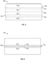
- FIG. 3 and 4 respectively show a side elevation view, and a top view of a spacer 104, in accordance with at least some embodiments. Similar to Figure 2 , the spacer 104 in Figure 3 includes two holes 202. As would be appreciated by those skilled in the art having the benefit of the disclosure, dashed lines 302 represent the maximum extent of arcuate portion 208 ( Figure 2 ). Similarly, the maximum extent of arcuate portion 208 is represented by dashed lines 402 ( Figure 4 ) and the edges of lateral portion 210, ( Figure 2 ) are represented by solid lines 404. For ease of illustration, interior volume 212 ( Figure 2 ) is omitted in the views of Figures 3 and 4 .
- FIG 5 shows a side elevation view of a portion of cable harness 204 including a harness plug 206 and a portion 502 of a cable bundle 207.
- Harness plug 206 may be molded over the cable bundle portion 502 wherein the material forming the harness plug 206 binds to the cables comprising cable bundle 207, e.g. cables 504, 508, 606 ( Figure 6 ), and also fills any interstices, e.g. interstices 608 ( Figure 6 ), that might subsist between the cables.
- harness plug 206 may form a unitary structure with and watertight seal about the portion 502 of cable bundle 507 comprising one or more cables e.g. cables 504, 508, 606 ( Figure 6 ).
- cable splices may be embedded within harness plug 206.
- a cable harness 204 may include electrical or optical cables, or a combination of electrical and optical cables for communicating data from a sensor to electrical circuitry for communicating the data along the marine streamer to a survey vessel.
- signal cables 504 from a sensor 506 may be spliced to cables 508 at splices 510.
- Cable 508 may be a data cable or, alternatively, may be another sensor signal cable.
- Splices 510 may be fabricated by soldering, or ultrasonic welding, if a wire cable, or an optical fusion splice if a cable comprises an optical fiber.
- a sensor 506 may be any sensor used in conjunction with a marine survey such as a hydrophone, geophone or other fluid particle motion sensor, such as an accelerometer.
- a sensor 506 may be disposed within the interior volume 212 ( Figure 2 ) of a spacer 104.
- Harness plug 206 may comprise a lateral portion 512 that is configured to engage with a lateral portion 210 ( Figure 2 ) of a hole 202, and an arcuate portion 514 configured to engage with arcuate portion 208 of a hole 202 ( Figure 2 ).
- lateral portion 512 and arcuate portion 514 of a harness plug 206 are shown in the cross-sectional view in Figure 6 .
- Lateral portion 512 is disposed at periphery 602 of arcuate portion 514.
- harness plug 206 may comprise a single unit of a molded polymer, such as a polyamide plastic, for example.
- the lateral portion 512 may be omitted wherein the harness plug 206 may comprise a cylindrical form in which arcuate portion 514 may have a circular form in cross-section.
- a harness plug 206 may comprise a molded material that includes a region 215 bonded to the cables 606 within a cable bundle 207 and filling interstices, e.g. interstice 608, between cables 606.
- cables 606 may comprise electrical cables, optical cables, or a combination thereof.
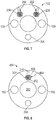
- FIG 7 shows a spacer 702 in accordance with at least some other exemplary embodiments.
- Spacer 702 may include two holes 202 configured to receive harness plugs 206.
- Spacer 702 may further include a hole 704 configured for the passage of a wire bundle (not shown in Figure 7 ) without the use of a harness plug.
- spacer 702 may include holes 103 for the passage of a stress member 102 ( Figure 1 ).
- FIG 8 shows a spacer 104 and harness plug 802 in accordance with at least some further embodiments.
- Harness plug 802 may include an arcuate portion 804 but omit a lateral portion.
- lateral portion 210 may be used to thread the cables within a cable bundle 207 into a hole 202 (shown filled by harness plug 802) in spacer 104 prior to fitting the harness plug 807.
- harness plugs e.g. harness plugs 206 ( Figure 2 )
- 802 may engage with a complementary hole in spacer 104 without the use of an adhesive.
- a harness plug 206 ( Figure 2 ) 802 may be press fit into a hole 202 without the use of an adhesive.
- a pin or screw may be used to secure a harness plug in the spacer.
- a hole may be provided to accommodate such a pin or screw, as illustrated in Figures 9A and 9B.
- Figure 9A shows a top view of a spacer 104 in accordance with such an embodiment.
- spacer 104 may have a lateral portion 210.
- Solid lines 904 represent the edges of lateral portion 210, and the maximum extent of arcuate portion 208 of a hole 202 ( Figure 2 ) is represented by dashed lines 906.
- interior volume 212 is not shown in Figure 9A .
- a hole 902 may be provided to accommodate a pin or screw (not shown in Figures 9A, 9B ) to engage with a harness plug (e.g. harness plug 206, 802, not shown in Figure 9A).
- Figure 9B shows a cross-sectional view of spacer 104 having a hole 902 disposed therein passing from outer surface 903 to periphery 602 of hole 202 to accommodate a fastening device such as a screw or pin to engage with arcuate portion 514 of harness plug 206.
- a hole 905 may be provided wherein the screw or pin engages with lateral portion 210.
- holes 902, 905 may be threaded (not shown in Figures 9A, 9B ) to accommodate a screw, such as a set screw.
- holes 902, 905 may comprise threads formed on an interior surface thereof (not shown in Figure 9A, 9B ) which are configured to retain a screw disposed within the holes.
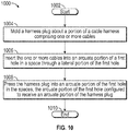
- Method 1000 may be used to deploy a cable bundle in conjunction with, for example, a spacer 104 or a spacer 702, using a harness plug (e.g. a harness plug 206) in accordance with at least some embodiments.
- Method 1000 starts at block 1002.
- a harness plug is molded about a portion of a cable bundle comprising one or more cables.
- the one or more cables are inserted into an arcuate portion of a first hole in a spacer (e.g.
- a lateral portion of the first hole such as a lateral portion 210 ( Figures 2 , 8 and 9A, 9B ), in block 1006.
- the lateral portion of the hole may be used in this way in conjunction with a harness plug having a complementary lateral portion, e.g. a lateral portion 512 ( Figure 5 ), or a harness plug comprising only an arcuate portion.
- the harness plug is pressed into the arcuate portion of the first hole in the spacer.
- the harness plug may be configured to engage with the hole, without the use of an adhesive.
- a second hole may be provided in the spacer passing from an outer surface of the spacer (e.g.
- Method 1000 ends at block 1010.
Landscapes
- Life Sciences & Earth Sciences (AREA)
- Physics & Mathematics (AREA)
- Remote Sensing (AREA)
- Engineering & Computer Science (AREA)
- Geophysics (AREA)
- Geology (AREA)
- Environmental & Geological Engineering (AREA)
- General Life Sciences & Earth Sciences (AREA)
- General Physics & Mathematics (AREA)
- Acoustics & Sound (AREA)
- Oceanography (AREA)
- Electromagnetism (AREA)
- Connector Housings Or Holding Contact Members (AREA)
- Installation Of Indoor Wiring (AREA)
Abstract
Description
- This disclosure is related generally to the field of marine surveying. Marine surveying can include, for example, seismic and/or electromagnetic (EM) surveying, among others. For example, this disclosure may have applications in marine surveying, in which one or more source elements are used to generate wave-fields, and sensors-either towed or ocean bottom-receive energy generated by the source elements and affected by the interaction with the subsurface formation. The sensors thereby collect survey data which can be useful in the discovery and/or extraction of hydrocarbons from subsurface formations.
- Some approaches to marine streamer production include pulling wire harnesses through holes in spacers that have been laid out on a table and fixed in place by the marine streamer stress members. The pulling of wire harnesses through all the spacers can be time consuming and can make repair challenging. Examples of marine streamers include seismic and EM streamers, among others. Thus, devices and methods that reduce the labor and complexity of the production of marine streamers would provide a competitive advantage in the art.
- For a detailed description of exemplary embodiments of the invention, reference will now be made to the accompanying drawings in which:
-
Figure 1 shows a perspective view of streamer spacer assemblies; -
Figure 2 shows a cross-sectional view of a spacer and harness plug in accordance with an embodiment; -
Figure 3 shows a side elevation view of a spacer in accordance with an embodiment; -
Figure 4 shows a top view of a spacer in accordance with an embodiment; -
Figure 5 shows a side view of a portion of a cable harness in accordance with an embodiment; -
Figure 6 shows a cross-sectional view of a harness plug in accordance with an embodiment; -
Figure 7 shows a cross-sectional view of a spacer in accordance with an embodiment; -
Figure 8 shows a cross-sectional view of a spacer in accordance with an embodiment; -
Figures 9A and 9B show a top view and cross-sectional elevation view, respectively, of a spacer in accordance with an embodiment; and -
Figure 10 shows a flow chart of a method in accordance with an embodiment. - Certain terms are used throughout the following description and claims to refer to particular system components. As one skilled in the art will appreciate, computer companies may refer to a component by different names. This document does not intend to distinguish between components that differ in name but not function. In the following discussion and in the claims, the terms "including" and "comprising" are used in an open-ended fashion, and thus should be interpreted to mean "including, but not limited to...." Also, the term "couple" or "couples" is intended to mean either an indirect, direct, optical or wireless electrical connection. Thus, if a first device couples to a second device, that connection may be through a direct electrical connection, through an indirect electrical connection via other devices and connections, through an optical electrical connection, or through a wireless electrical connection.
- "Rope" shall mean a flexible, axial load carrying member that does not include electrical and/or optical conductors. Such a rope may be made from fiber, steel, other high strength material, chain, or combinations of such materials.
- The following discussion is directed to various embodiments of the invention. Although one or more of these embodiments may be preferred, the embodiments disclosed should not be interpreted, or otherwise used, as limiting the scope of the disclosure, including the claims. In addition, one skilled in the art will understand that the following description has broad application, and the discussion of any embodiment is meant only to be exemplary of that embodiment, and not intended to intimate that the scope of the disclosure, including the claims, is limited to that embodiment.
- Turning to
Figure 1, Figure 1 shows a perspective view ofspacer assemblies 100 laid out withstress members 102 threaded throughholes 103 inspacers 104.Spacers 104 may comprise anelongate body 106 having a length, andholes 103 may pass through the length of theelongate body 106, as described further below. In various embodiments,elongate body 106 of aspacer 104 may be plastic or metallic. For example, in at least some embodiments,elongate body 106 may comprise an engineered thermoplastic such as an ISOPLAST® engineered polymer from Lubrizol Corporation, Wickliffe, OH, USA. In at least some other embodiments, anelongate body 106 may comprise a foam polypropylene, and in still other embodiments may comprise a metal such as aluminum. By way of example, aspacer 104 comprising a metallicelongate body 106 may be used where weight of thespacer 104 is not a concern and high strength is desired. In at least some embodiments,stress members 102 may comprise rope. To further the production of a marine streamer, one or more cable harnesses comprising a plurality of electrical and/or optical cables may be pulled through other holes (not visible inFigure 1 ) inspacers 104, as will now be described in conjunction withFigure 2 . -
Figure 2 shows a front elevation view of aspacer 104 in accordance with at least some embodiments.Spacer 104 includesholes 103 through which stress members (not shown inFigure 2 ) may thread, as described in conjunction withFigure 1 .Holes 202 may be provided for the passage of one or more cable harnesses 204 through thespacers 104.Holes 202 may be disposed about aperipheral axis 203 which may be disposed at a circumference about acentral axis 205.Central axis 205 may define a center of aninterior volume 212 of aspacer 104. In particular, in embodiments in accordance with the principles disclosed, acable harness 204 may comprise acable bundle 207 and aharness plug 206 disposed about thecable bundle 207 to facilitate assembly of a marine streamer.Plug 206 may include aregion 215 bonded tocable bundle 207 as described further in conjunction withFigure 6 .Cable bundle 207 may include one or more electrical, or optical cables, or a combination thereof. - A
harness plug 206 may be configured to engage with ahole 202 having a shape complementary to that of theharness plug 206. In the exemplary embodiment ofFigure 2 ,holes 202 are shown with a "keyhole" like shape with a first portion comprising an arcuate shape, e.g.arcuate portion 208 and a second portion lateral to and abutting thearcuate portion 208, e.g. alateral portion 210, and extending to aperiphery 214 of theelongate body 106. In other words, in at least some embodiments, a lateral portion of a harness plug, e.g. lateral portion 512 (Figure 5 ) may be configured to engage a complementary slot in a keyhole-shaped hole disposed in a spacer 104 (Figure 2 ). In other embodiments, different shapes may be used. In at least some embodiments,arcuate portion 208 may be circular in shape. And in at least some embodiments,lateral portion 210 may comprise a slot portion (or, simply slot) extending along a length of theelongate body 106. Further, while twoholes 202 are shown in the embodiment inFigure 2 , in other embodiments asingle hole 202 may be used, and in still other embodiments, more than twoholes 202 may be used. In at least some embodiments, the two or more holes may have a keyhole shape. In still other embodiments, at least one of the two ormore holes 202 may have a circular shape without a lateral portion (not shown inFigure 2 ). - The arrangement of
holes 202 and in relation toelongate body 106 may be further appreciated by referring to Figured 3 and 4 which respectively show a side elevation view, and a top view of aspacer 104, in accordance with at least some embodiments. Similar toFigure 2 , thespacer 104 inFigure 3 includes twoholes 202. As would be appreciated by those skilled in the art having the benefit of the disclosure, dashedlines 302 represent the maximum extent of arcuate portion 208 (Figure 2 ). Similarly, the maximum extent ofarcuate portion 208 is represented by dashed lines 402 (Figure 4 ) and the edges oflateral portion 210, (Figure 2 ) are represented bysolid lines 404. For ease of illustration, interior volume 212 (Figure 2 ) is omitted in the views ofFigures 3 and 4 . -
Figure 5 shows a side elevation view of a portion ofcable harness 204 including aharness plug 206 and a portion 502 of acable bundle 207.Harness plug 206 may be molded over the cable bundle portion 502 wherein the material forming theharness plug 206 binds to the cables comprisingcable bundle 207,e.g. cables Figure 6 ), and also fills any interstices, e.g. interstices 608 (Figure 6 ), that might subsist between the cables. In this way,harness plug 206 may form a unitary structure with and watertight seal about the portion 502 of cable bundle 507 comprising one or more cables e.g.cables Figure 6 ). Additionally, cable splices may be embedded withinharness plug 206. For example, acable harness 204 may include electrical or optical cables, or a combination of electrical and optical cables for communicating data from a sensor to electrical circuitry for communicating the data along the marine streamer to a survey vessel. Thus,signal cables 504 from asensor 506 may be spliced tocables 508 atsplices 510.Cable 508 may be a data cable or, alternatively, may be another sensor signal cable.Splices 510 may be fabricated by soldering, or ultrasonic welding, if a wire cable, or an optical fusion splice if a cable comprises an optical fiber. As would be appreciated by those skilled in the art having the benefit of the disclosure, asensor 506 may be any sensor used in conjunction with a marine survey such as a hydrophone, geophone or other fluid particle motion sensor, such as an accelerometer. In at least some embodiments, when acable harness 204 is incorporated within a marine streamer comprising a spacer assembly 100 (Figure 1 ), asensor 506 may be disposed within the interior volume 212 (Figure 2 ) of aspacer 104.Harness plug 206 may comprise alateral portion 512 that is configured to engage with a lateral portion 210 (Figure 2 ) of ahole 202, and anarcuate portion 514 configured to engage witharcuate portion 208 of a hole 202 (Figure 2 ). - The relationship of the
lateral portion 512 andarcuate portion 514 of aharness plug 206 is shown in the cross-sectional view inFigure 6 .Lateral portion 512 is disposed atperiphery 602 ofarcuate portion 514. In at least some embodiments,harness plug 206 may comprise a single unit of a molded polymer, such as a polyamide plastic, for example. Further, in at least some alternative embodiments, thelateral portion 512 may be omitted wherein theharness plug 206 may comprise a cylindrical form in whicharcuate portion 514 may have a circular form in cross-section. As described above, aharness plug 206 may comprise a molded material that includes aregion 215 bonded to thecables 606 within acable bundle 207 and filling interstices,e.g. interstice 608, betweencables 606. In at least some embodiments,cables 606 may comprise electrical cables, optical cables, or a combination thereof. -
Figure 7 shows aspacer 702 in accordance with at least some other exemplary embodiments.Spacer 702 may include twoholes 202 configured to receive harness plugs 206.Spacer 702 may further include ahole 704 configured for the passage of a wire bundle (not shown inFigure 7 ) without the use of a harness plug. Similar to a spacer 104 (Figures 1 and 2 ),spacer 702 may includeholes 103 for the passage of a stress member 102 (Figure 1 ). -
Figure 8 shows aspacer 104 and harnessplug 802 in accordance with at least some further embodiments.Harness plug 802 may include anarcuate portion 804 but omit a lateral portion. As described further in conjunction withFigure 10 ,lateral portion 210 may be used to thread the cables within acable bundle 207 into a hole 202 (shown filled by harness plug 802) inspacer 104 prior to fitting the harness plug 807. Further, as described in conjunction withFigure 10 , harness plugs, e.g. harness plugs 206 (Figure 2 ), 802 may engage with a complementary hole inspacer 104 without the use of an adhesive. In at least some embodiments a harness plug 206 (Figure 2 ), 802 may be press fit into ahole 202 without the use of an adhesive. - In at least some embodiments, a pin or screw may be used to secure a harness plug in the spacer. Thus, a hole may be provided to accommodate such a pin or screw, as illustrated in
Figures 9A and 9B. Figure 9A shows a top view of aspacer 104 in accordance with such an embodiment. As inFigures 2 and8 ,spacer 104 may have alateral portion 210.Solid lines 904 represent the edges oflateral portion 210, and the maximum extent ofarcuate portion 208 of a hole 202 (Figure 2 ) is represented by dashedlines 906. For ease of illustration,interior volume 212 is not shown inFigure 9A . Ahole 902 may be provided to accommodate a pin or screw (not shown inFigures 9A, 9B ) to engage with a harness plug (e.g. harness plug Figure 9A). Figure 9B shows a cross-sectional view ofspacer 104 having ahole 902 disposed therein passing fromouter surface 903 toperiphery 602 ofhole 202 to accommodate a fastening device such as a screw or pin to engage witharcuate portion 514 ofharness plug 206. Alternatively, or in at lease some embodiments additionally, ahole 905 may be provided wherein the screw or pin engages withlateral portion 210. In at least some embodiments, holes 902, 905 may be threaded (not shown inFigures 9A, 9B ) to accommodate a screw, such as a set screw. In other words, holes 902, 905 may comprise threads formed on an interior surface thereof (not shown inFigure 9A, 9B ) which are configured to retain a screw disposed within the holes. - Turning now to
Figure 10 , a flow chart of amethod 1000 for deploying a cable bundle within a spacer is shown.Method 1000 may be used to deploy a cable bundle in conjunction with, for example, aspacer 104 or aspacer 702, using a harness plug (e.g. a harness plug 206) in accordance with at least some embodiments.Method 1000 starts atblock 1002. Inblock 1004, a harness plug is molded about a portion of a cable bundle comprising one or more cables. The one or more cables are inserted into an arcuate portion of a first hole in a spacer (e.g. hole 202,Figure 2 ) through a lateral portion of the first hole, such as a lateral portion 210 (Figures 2 ,8 and9A, 9B ), inblock 1006. The lateral portion of the hole may be used in this way in conjunction with a harness plug having a complementary lateral portion, e.g. a lateral portion 512 (Figure 5 ), or a harness plug comprising only an arcuate portion. Inblock 1008 the harness plug is pressed into the arcuate portion of the first hole in the spacer. The harness plug may be configured to engage with the hole, without the use of an adhesive. Further, as described above, a second hole may be provided in the spacer passing from an outer surface of the spacer (e.g. outer surface 903 (Figures 9A, 9B ) traversing the spacer to the arcuate portion of the first hole, e.g. hole 902 (Figure 9A, 9B ). Alternatively, a second hole may be provided in the spacer traversing the spacer to the lateral portion of the first hole, e.g. hole 905 (Figures 9A, 9B ). The second hole may be configured to retain a fastening device such as a pin or screw. The fastening device may engage with the harness plug to further restrain the harness plug in the spacer, for example.Method 1000 ends atblock 1010. - The above discussion is meant to be illustrative of the principles and various embodiments of the present invention. Numerous variations and modifications will become apparent to those skilled in the art once the above disclosure is fully appreciated. For example, spacer assemblies incorporating cable harnesses and harness plugs in accordance with the principles of the disclosed embodiments may have any number of harness plugs. It is intended that the following claims be interpreted to embrace all such variations and modifications.
Claims (15)
- A streamer spacer comprising:an elongate body having a length;one or more holes passing through the length of the elongate body; andwherein a first hole comprises:a first portion having an arcuate shape; anda second portion lateral to and abutting the arcuate portion and extending to a periphery of the elongate body.
- The streamer spacer of claim 1 wherein the shape of the first hole is a keyhole shape.
- The streamer spacer of claim 1 or claim 2 wherein the arcuate portion of the first hole comprises a circular curve and the second portion comprises a slot portion extending from the circular curve to the periphery of the elongate body.
- The streamer spacer of any of claims 1-3 wherein:the elongate body further comprises an outer surface, the device further comprising:a hole passing from the outer surface to a periphery of the arcuate portion of the first hole, the hole passing from the outer surface of the elongate body configured to retain a device for securing a harness plug in the first hole.
- A cable harness comprising:a cable bundle comprising one or more cables; andone or more harness plugs, wherein:each harness plug is molded about the cable bundle and forms a watertight seal about the one or more cables of the cable bundle; and wherein:each harness plug has an arcuate portion having a curved boundary, the arcuate portion configured to engage with the arcuate portion of the first hole within the streamer spacer of any of claims 1-4.
- The cable harness of claim 5 wherein at least one of the one or more harness plugs further comprises a lateral portion disposed at an outer periphery of the arcuate portion.
- The cable harness of claim 6 wherein the lateral portion is configured to engage a complementary slot in a keyhole-shaped hole disposed in the spacer.
- The cable harness of any of claims 5-7 wherein each harness plug comprises a polyamide plastic.
- A harness plug comprising:an arcuate portion; anda lateral portion disposed at an outer periphery of the arcuate portion, wherein the arcuate portion is configured to engage with arcuate portion of a hole within a spacer; andwherein the harness plug is configured to form a watertight seal about a portion of a cable harness comprising one or more cables.
- The harness plug of claim 9 wherein the arcuate portion and the lateral portion comprise a polyamide plastic.
- The harness plug of claim 9 or claim 10 wherein the harness plug is configured to engage with the hole within the spacer without the use of an adhesive.
- A method for deploying a cable bundle in a spacer comprising:molding a harness plug about a portion of the cable bundle comprising one or more cables;inserting the one or more cables into an arcuate portion of a first hole in the spacer through a lateral portion of the first hole; andpressing the harness plug into the arcuate portion of the first hole in the spacer, the arcuate portion of the first hole configured to receive an arcuate portion of the harness plug.
- The method of claim 12 wherein the harness plug is pressed into the first hole without the use of an adhesive.
- The method of claim 12 or claim 13 further comprising:inserting a fastening device in a second hole in the spacer, the second hole traversing the spacer from an outer surface of the spacer to the arcuate portion of the first hole; andengaging the harness plug with the fastening device.
- The method of claim 12 or claim 13 further comprising:inserting a fastening device in a second hole in the spacer, the second hole traversing the spacer from an outer surface of the spacer to a lateral portion of the first hole; andengaging the harness plug with the fastening device.
Applications Claiming Priority (2)
| Application Number | Priority Date | Filing Date | Title |
|---|---|---|---|
| US201662357179P | 2016-06-30 | 2016-06-30 | |
| US15/626,758 US10557953B2 (en) | 2016-06-30 | 2017-06-19 | Molded snap-in plug and device and method for using same |
Publications (1)
| Publication Number | Publication Date |
|---|---|
| EP3264141A1 true EP3264141A1 (en) | 2018-01-03 |
Family
ID=59227619
Family Applications (1)
| Application Number | Title | Priority Date | Filing Date |
|---|---|---|---|
| EP17178108.1A Withdrawn EP3264141A1 (en) | 2016-06-30 | 2017-06-27 | Molded snap-in plug and device and method for using same |
Country Status (2)
| Country | Link |
|---|---|
| US (1) | US10557953B2 (en) |
| EP (1) | EP3264141A1 (en) |
Citations (10)
| Publication number | Priority date | Publication date | Assignee | Title |
|---|---|---|---|---|
| GB1497737A (en) * | 1974-07-10 | 1978-01-12 | Felten & Guilleaume Kabelwerk | Electric cables with tension-supporting elements |
| US4500980A (en) * | 1981-08-24 | 1985-02-19 | Whitehall Corporation | Seismic streamer connector assembly |
| US4638469A (en) * | 1983-05-18 | 1987-01-20 | Britoil Public Limited Company | Mechanical spacer for towed acoustic array |
| US4725990A (en) * | 1983-05-18 | 1988-02-16 | Shell Offshore Inc. | Marine shear cable |
| US5943293A (en) * | 1996-05-20 | 1999-08-24 | Luscombe; John | Seismic streamer |
| US6477111B1 (en) * | 1998-10-29 | 2002-11-05 | Schlumberger Technology Corporation | Method of making a marine seismic streamer |
| US20070193768A1 (en) * | 2002-03-07 | 2007-08-23 | Eugene Howe | Interconnecting cable |
| US20100165792A1 (en) * | 2008-12-26 | 2010-07-01 | Andre Stenzel | Marine seismic streamer cable with noise suppressing sensor support |
| US20100206586A1 (en) * | 2009-02-13 | 2010-08-19 | The Board Of Regents Of The Nevada System Of Higher Education, | Sampling system and method |
| JP2016001521A (en) * | 2014-06-11 | 2016-01-07 | 矢崎総業株式会社 | charging cable |
Family Cites Families (45)
| Publication number | Priority date | Publication date | Assignee | Title |
|---|---|---|---|---|
| US4736345A (en) | 1987-03-27 | 1988-04-05 | Mobil Oil Corporation | Compliant spacer for a marine seismic streamer |
| US5058080A (en) | 1988-12-05 | 1991-10-15 | Western Atlas International, Inc. | Multiple transmission path seismic telemetering system |
| US5561640A (en) | 1995-05-22 | 1996-10-01 | The United States Of America As Represented By The Secretary Of The Navy | Multi-section sonar array cable |
| US5883857A (en) | 1996-11-07 | 1999-03-16 | Innovative Transducers Incorporated | Non-liquid filled streamer cable with a novel hydrophone |
| US5883856A (en) | 1997-10-31 | 1999-03-16 | Input/Output, Inc. | Power switching method for marine seismic acquisition systems |
| US6009042A (en) | 1998-04-09 | 1999-12-28 | Western Atlas International, Inc. | Marine seismic web |
| GB9807997D0 (en) | 1998-04-15 | 1998-06-17 | Geco As | Automated streamer production |
| US6229706B1 (en) | 1998-04-27 | 2001-05-08 | Aavid Thermal Products, Inc. | Reverse cantilever spring clip |
| US6337636B1 (en) | 1998-09-16 | 2002-01-08 | Cirrus Logic, Inc. | System and techniques for seismic data acquisition |
| US6816082B1 (en) | 1998-11-17 | 2004-11-09 | Schlumberger Technology Corporation | Communications system having redundant channels |
| US6229760B1 (en) | 1999-04-01 | 2001-05-08 | Western Geco | Integrated streamer acoustic pod |
| GB0010636D0 (en) | 2000-05-04 | 2000-06-28 | Geco As | Acoustic emitters for use in marine seismic surveying |
| US6612886B2 (en) | 2001-09-06 | 2003-09-02 | Concord Technologies | In-line cable retriever |
| WO2003048809A2 (en) | 2001-11-30 | 2003-06-12 | Input/Output, Inc. | Permanently installed seismic ocean bottom cable |
| US6879546B2 (en) | 2002-02-14 | 2005-04-12 | Westerngeco, L.L.C. | Gel-filled seismic streamer cable |
| AU2003278901B2 (en) | 2002-09-23 | 2009-12-03 | Ion Geophysical Corporation | Seafloor seismic recording using MEMS |
| GB2410551B (en) | 2004-01-30 | 2006-06-14 | Westerngeco Ltd | Marine seismic acquisition system |
| US7366055B2 (en) | 2006-05-05 | 2008-04-29 | Optoplan As | Ocean bottom seismic sensing system |
| CA2628997C (en) | 2007-04-13 | 2015-11-17 | Xact Downhole Telemetry Inc. | Drill string telemetry method and apparatus |
| US7622706B2 (en) | 2008-01-18 | 2009-11-24 | Pgs Geophysical As | Sensor cable and multiplexed telemetry system for seismic cables having redundant/reversible optical connections |
| NO332562B1 (en) | 2008-07-04 | 2012-10-29 | Multifield Geophysics As | Marine seismic and electromagnetic streamer cable |
| US8094519B2 (en) | 2009-08-19 | 2012-01-10 | The United States Of America As Represented By The Secretary Of The Navy | Intensity modulated fiber optic hydrophones |
| US8995221B2 (en) | 2009-09-08 | 2015-03-31 | Pgs Geophysical As | Towed marine sensor streamer having concentric stress member |
| US8520469B2 (en) | 2009-10-12 | 2013-08-27 | Westerngeco L.L.C. | Sensor assembly having a seismic sensor, pressure sensor, and processor to apply first and second digital filters |
| US9019797B2 (en) | 2010-06-10 | 2015-04-28 | Westerngeco L.L.C. | Deghosting using measurement data from seismic sensors |
| US20120069706A1 (en) | 2010-09-20 | 2012-03-22 | Nicolas Goujon | Land Seismic Cable and Method |
| US9217805B2 (en) | 2010-10-01 | 2015-12-22 | Westerngeco L.L.C. | Monitoring the quality of particle motion data during a seismic acquisition |
| US20120081994A1 (en) | 2010-10-01 | 2012-04-05 | Vidar Anders Husom | Seismic Streamer Connection Unit |
| US20120250457A1 (en) | 2011-03-28 | 2012-10-04 | Pgs Americas, Inc. | Systems and methods for wireless communication in a geophysical survey streamer |
| KR101290913B1 (en) | 2012-04-30 | 2013-07-29 | 한국지질자원연구원 | Submarine data relay system and method |
| US8998535B2 (en) | 2012-05-18 | 2015-04-07 | Pgs Geophysical As | Method and system of retriever systems for marine geophysical survey sensor streamers |
| US9038765B2 (en) | 2012-06-26 | 2015-05-26 | Schlumberger Technology Corporation | Neutrally-buoyant borehole investigation tools and methods |
| EP2690468B1 (en) | 2012-07-27 | 2019-03-27 | Sercel | A streamer for seismic prospection comprising tilt compensation of directional sensors |
| EP2720069B1 (en) | 2012-10-12 | 2022-06-15 | Sercel | A seismic cable for seismic prospection tolerant to failure on power supplying and/or data transmission lines |
| US10156650B2 (en) | 2013-03-15 | 2018-12-18 | Wireless Seismic, Inc. | Multimode seismic unit and associated methodology |
| US9482783B2 (en) | 2013-06-19 | 2016-11-01 | Cgg Services Sa | Systems and methods for reducing marine fouling |
| US9417346B2 (en) | 2013-08-29 | 2016-08-16 | Westerngeco L.L.C. | Seismic vibrator device and method with rotation sensor |
| US9715038B2 (en) | 2013-09-30 | 2017-07-25 | Sercel Inc. | Marine cable support system and method |
| US9459944B2 (en) | 2013-10-30 | 2016-10-04 | Pgs Geophysical As | Method and system for streamer redundancy |
| US10591622B2 (en) | 2013-10-30 | 2020-03-17 | Pgs Geophysical As | Reconfigurable seismic sensor cable |
| US10302429B2 (en) | 2014-02-07 | 2019-05-28 | Conocophillips Company | Seismic streamer shape correction using derived compensated magnetic fields |
| WO2015170170A2 (en) | 2014-05-06 | 2015-11-12 | Cgg Services Sa | Source controller system for marine seismic source and method |
| US10012751B2 (en) | 2014-06-18 | 2018-07-03 | Pgs Geophysical As | Electrode adapter for geophysical surveys |
| WO2015195939A1 (en) | 2014-06-19 | 2015-12-23 | Westerngeco Llc | System and method to acquire ultra-long offset seismic data for full waveform inversion (fwi) using unmanned marine vehicle (umv) |
| WO2016007505A1 (en) | 2014-07-08 | 2016-01-14 | Westerngeco Llc | Multi-dimensional folding seismic sensor array |
-
2017
- 2017-06-19 US US15/626,758 patent/US10557953B2/en not_active Expired - Fee Related
- 2017-06-27 EP EP17178108.1A patent/EP3264141A1/en not_active Withdrawn
Patent Citations (10)
| Publication number | Priority date | Publication date | Assignee | Title |
|---|---|---|---|---|
| GB1497737A (en) * | 1974-07-10 | 1978-01-12 | Felten & Guilleaume Kabelwerk | Electric cables with tension-supporting elements |
| US4500980A (en) * | 1981-08-24 | 1985-02-19 | Whitehall Corporation | Seismic streamer connector assembly |
| US4638469A (en) * | 1983-05-18 | 1987-01-20 | Britoil Public Limited Company | Mechanical spacer for towed acoustic array |
| US4725990A (en) * | 1983-05-18 | 1988-02-16 | Shell Offshore Inc. | Marine shear cable |
| US5943293A (en) * | 1996-05-20 | 1999-08-24 | Luscombe; John | Seismic streamer |
| US6477111B1 (en) * | 1998-10-29 | 2002-11-05 | Schlumberger Technology Corporation | Method of making a marine seismic streamer |
| US20070193768A1 (en) * | 2002-03-07 | 2007-08-23 | Eugene Howe | Interconnecting cable |
| US20100165792A1 (en) * | 2008-12-26 | 2010-07-01 | Andre Stenzel | Marine seismic streamer cable with noise suppressing sensor support |
| US20100206586A1 (en) * | 2009-02-13 | 2010-08-19 | The Board Of Regents Of The Nevada System Of Higher Education, | Sampling system and method |
| JP2016001521A (en) * | 2014-06-11 | 2016-01-07 | 矢崎総業株式会社 | charging cable |
Also Published As
| Publication number | Publication date |
|---|---|
| US10557953B2 (en) | 2020-02-11 |
| US20180003835A1 (en) | 2018-01-04 |
Similar Documents
| Publication | Publication Date | Title |
|---|---|---|
| US7679989B2 (en) | Ocean bottom seismic station | |
| US5274603A (en) | Marine seismic cable section assembly | |
| US8319497B2 (en) | Marine sensor streamer having pressure activated stiffness enhancement | |
| AU762817B2 (en) | Method of making a marine seismic streamer | |
| US6278823B1 (en) | Sensor array cable and fabrication method | |
| EP2293115A2 (en) | Towed marine sensor streamer having concentric stress member | |
| US10222572B2 (en) | Clamp and bending strain relief apparatus and methods | |
| US10295689B2 (en) | Controlled curvature bend device and method | |
| NO336410B1 (en) | Permanently installed seismic seabed cable | |
| US10557953B2 (en) | Molded snap-in plug and device and method for using same | |
| US11199639B2 (en) | Borehole seismic sensor array and associated methods | |
| US9823433B2 (en) | Staggered optical fiber splices | |
| US10101478B2 (en) | Flexible printed circuits in marine geophysical streamers | |
| US4744065A (en) | Reinforcing device in the inner portion of seismic cables | |
| RU152826U1 (en) | TRANSMISSION CABLE SUPPORTED BY ANCHOR | |
| US20200150300A1 (en) | Streamer manufacturing | |
| WO2011134890A1 (en) | Carrier module for an underwater antenna and method for fastening a converter element to such a carrier module | |
| KR102756911B1 (en) | Fiber armour fixing device and underwater cable connecting system having the same | |
| US8670291B2 (en) | Method and apparatus for terminating rope and its application to seismic streamer strength members | |
| NO342889B1 (en) | Divisible spacer and method for assembling structure components of a marine seismic streamer | |
| GB2161446A (en) | Strainwire termination |
Legal Events
| Date | Code | Title | Description |
|---|---|---|---|
| PUAI | Public reference made under article 153(3) epc to a published international application that has entered the european phase |
Free format text: ORIGINAL CODE: 0009012 |
|
| AK | Designated contracting states |
Kind code of ref document: A1 Designated state(s): AL AT BE BG CH CY CZ DE DK EE ES FI FR GB GR HR HU IE IS IT LI LT LU LV MC MK MT NL NO PL PT RO RS SE SI SK SM TR |
|
| AX | Request for extension of the european patent |
Extension state: BA ME |
|
| 17P | Request for examination filed |
Effective date: 20180516 |
|
| RBV | Designated contracting states (corrected) |
Designated state(s): AL AT BE BG CH CY CZ DE DK EE ES FI FR GB GR HR HU IE IS IT LI LT LU LV MC MK MT NL NO PL PT RO RS SE SI SK SM TR |
|
| 17Q | First examination report despatched |
Effective date: 20200717 |
|
| STAA | Information on the status of an ep patent application or granted ep patent |
Free format text: STATUS: THE APPLICATION IS DEEMED TO BE WITHDRAWN |
|
| 18D | Application deemed to be withdrawn |
Effective date: 20201128 |