EP3264129B1 - Mehrfachplattformstandorttäuschungssystem - Google Patents
Mehrfachplattformstandorttäuschungssystem Download PDFInfo
- Publication number
- EP3264129B1 EP3264129B1 EP17178994.4A EP17178994A EP3264129B1 EP 3264129 B1 EP3264129 B1 EP 3264129B1 EP 17178994 A EP17178994 A EP 17178994A EP 3264129 B1 EP3264129 B1 EP 3264129B1
- Authority
- EP
- European Patent Office
- Prior art keywords
- platforms
- emission
- platform
- subset
- location
- Prior art date
- Legal status (The legal status is an assumption and is not a legal conclusion. Google has not performed a legal analysis and makes no representation as to the accuracy of the status listed.)
- Active
Links
Images


Classifications
-
- H—ELECTRICITY
- H04—ELECTRIC COMMUNICATION TECHNIQUE
- H04K—SECRET COMMUNICATION; JAMMING OF COMMUNICATION
- H04K3/00—Jamming of communication; Counter-measures
- H04K3/60—Jamming involving special techniques
- H04K3/65—Jamming involving special techniques using deceptive jamming or spoofing, e.g. transmission of false signals for premature triggering of RCIED, for forced connection or disconnection to/from a network or for generation of dummy target signal
-
- G—PHYSICS
- G01—MEASURING; TESTING
- G01S—RADIO DIRECTION-FINDING; RADIO NAVIGATION; DETERMINING DISTANCE OR VELOCITY BY USE OF RADIO WAVES; LOCATING OR PRESENCE-DETECTING BY USE OF THE REFLECTION OR RERADIATION OF RADIO WAVES; ANALOGOUS ARRANGEMENTS USING OTHER WAVES
- G01S13/00—Systems using the reflection or reradiation of radio waves, e.g. radar systems; Analogous systems using reflection or reradiation of waves whose nature or wavelength is irrelevant or unspecified
- G01S13/66—Radar-tracking systems; Analogous systems
- G01S13/72—Radar-tracking systems; Analogous systems for two-dimensional tracking, e.g. combination of angle and range tracking, track-while-scan radar
- G01S13/723—Radar-tracking systems; Analogous systems for two-dimensional tracking, e.g. combination of angle and range tracking, track-while-scan radar by using numerical data
-
- G—PHYSICS
- G01—MEASURING; TESTING
- G01S—RADIO DIRECTION-FINDING; RADIO NAVIGATION; DETERMINING DISTANCE OR VELOCITY BY USE OF RADIO WAVES; LOCATING OR PRESENCE-DETECTING BY USE OF THE REFLECTION OR RERADIATION OF RADIO WAVES; ANALOGOUS ARRANGEMENTS USING OTHER WAVES
- G01S7/00—Details of systems according to groups G01S13/00, G01S15/00, G01S17/00
- G01S7/02—Details of systems according to groups G01S13/00, G01S15/00, G01S17/00 of systems according to group G01S13/00
- G01S7/38—Jamming means, e.g. producing false echoes
-
- G—PHYSICS
- G05—CONTROLLING; REGULATING
- G05B—CONTROL OR REGULATING SYSTEMS IN GENERAL; FUNCTIONAL ELEMENTS OF SUCH SYSTEMS; MONITORING OR TESTING ARRANGEMENTS FOR SUCH SYSTEMS OR ELEMENTS
- G05B15/00—Systems controlled by a computer
- G05B15/02—Systems controlled by a computer electric
-
- G—PHYSICS
- G06—COMPUTING OR CALCULATING; COUNTING
- G06F—ELECTRIC DIGITAL DATA PROCESSING
- G06F1/00—Details not covered by groups G06F3/00 - G06F13/00 and G06F21/00
- G06F1/04—Generating or distributing clock signals or signals derived directly therefrom
- G06F1/14—Time supervision arrangements, e.g. real time clock
Definitions
- the present subject matter relates generally to providing location deception and more particularly to providing angular location deception using a plurality of platforms.
- Deception techniques can be used to mislead an adverse observer as to the location of a vehicle. For instance, an aircraft can create deception as to the distance and/or speed of the aircraft, thereby misleading the observer as to the actual location of the aircraft. However, the observers can overcome such deception by deploying multiple observation angles to determine the actual aircraft position based on line-of-sight of each observation angle to the aircraft.
- US 6 697 008 B1 discloses a distributed electronic warfare system including a central control site for controlling and receiving data from multiple electronic warfare pods mounted to airplanes and utilizing a satellite communications system for communications within the system.
- the electronic warfare pods listen to signals from targets and jam the targets under control of the central control site.
- the pods have antennas for radiating jamming signals to the targets and receiving signals from the targets.
- the pods may be used for search and collection, geolocation, and electronic attack under control of the central control site.
- US 2009/128394 A1 discloses an active RF decoy simulation apparatus for simulating an active RF decoy system in virtual environment.
- US 2015/219459 A1 discloses a method for estimating a boundary for a future location of a moving object.
- PURVIS K B ET AL "Estimation and Optimal Configurations for Localization Using Cooperative UAVs", IEEE TRANSACTIONS ON CONTROL SYSTEMS TECHNOLOGY, IEEE SERVICE CENTER, NEW YORK, NY, US, vol. 16, no. 5, 1 September 2008, XP011225894 , explores position estimation using Time-Difference Of Arrival (TDOA) techniques.
- TDOA Time-Difference Of Arrival
- YUNJUN XU ET AL "Virtual motion camouflage based phantom track generation through cooperative electronic combat air vehicles", AUTOMATICA, vol. 46, no. 9, 1 September 2010, XP055424207 , discloses a bio-inspired motion strategy for phantom track generation.
- Claim 1 defines a computer implemented method
- claim 10 defines a computer system
- claim 13 defines a system.
- Example aspects of the present disclosure are directed to systems and methods for providing a synthetic track to one or more observation devices.
- a computing system e.g., associated with an operations/command center coordinates a plurality of platforms to generate a sequence of either responsive or non-responsive emissions to project a synthetic track.
- the platforms can include, for instance, multi-function emitter platforms, UAVs, aerial platforms, water platforms, platforms capable of traveling/operating underwater, platforms capable of operating in outer space, etc.
- the synthetic track can be a false object travel path and/or a realistic implied vehicle path (or paths) that can be observable by the one or more observation device(s) (e.g., radar devices of an adverse entity).
- the orientation of the synthetic track can be different from the actual travel paths of the platforms.
- the synthetic, of false, track intentionally may be designed to not correspond with the physical motion of any platforms.
- the synthetic track can create angular deception to mislead the observation devices as to the actual travel paths and/or locations of the platforms. To do so, for example, the synthetic track can be associated with a bearing angle that is different than the travel paths of the platforms.
- the computing system determines a location and/or time range in which to create such a synthetic track. Based, at least in part, on the prescribed location and/or time range the computing system determines a sequence of location and time pairings for each platform of the plurality of platforms (e.g., a swarm of aerial platforms) to generate an emission.
- the computing system sends data indicative of the emission times and/or locations to the platforms such that the platforms generate the emissions in a sequence to create the synthetic track within the location range and/or the time range.
- the sequence of emissions (or delayed versions of existing radar or communications signals) from the various platforms can create one of more false targets which appear to move in space. Any single emission will appear along the radial between the platform and any particular observer, but subsequent emissions move to a new radial creating apparent bearing change and angular deception.
- the computing system can identify a travel path for each platform of the plurality of platforms. This can be done while one or more of the platforms are deployed (e.g., a swarm of airborne platforms) and/or before one or more of the platforms are deployed.
- one or more of the platform(s) can be associated with one or more static travel path(s), such that the respective platform remains generally at a single location. In such a case, the stationary platforms can exist along a line and sequential emissions can create the appearance of motion, as further described herein.
- one or more of the platform(s) can be associated with one or more non-static travel path(s), such that the platform(s) can travel in space, for example, in a parallel and/or arbitrary manner relative to one another.
- the computing system determines a location range and/or a time range for a synthetic track to be created by the plurality of platforms. In some implementations, this determination can be based, at least in part, on the travel path for each platform. For example, a very large number of platforms can be deployed within minimal constraints on four dimensional locations.
- the computing system can dynamically select/prescribe the actions of the platforms (e.g., generating emissions to create a synthetic track) based, at least in part, on the travel paths of the platforms. Additionally, and/or alternatively, the location range and/or the time range can be based, at least in part, on the position, type, orientation, etc. of the one or more observation device(s).
- the computing system determines an emission location and/or an emission time for each of the plurality of platforms based, at least in part, on the location range and/or the time range.
- the emission location is indicative of a location at which the respective platform is to generate an emission.
- the emission time is indicative of a time at which the respective platform is to generate the emission.
- the emission locations and/or emission times can be selected to create the appearance of motion along a synthetic track.
- the apparent speed (of the "false" target moving along the synthetic track) can be selected by the ratio of the physical spacing between platforms and/or emissions divided by the time between emissions.
- the computing system sends a set of data to each of the plurality of platforms.
- Each respective set of data can indicate the emission location and/or the emission time at which the respective platform is to generate the emission to create the synthetic track.
- the computing device(s) can coordinate the platforms such that they are to generate the emissions in a sequence based, at least in part, on the emission locations and/or the emission times to create the synthetic track within the desired location range and/or the time range.
- the platforms can receive the sets of data and generate the emissions, at the emission times and/or locations, to create the synthetic track.
- the observed synthetic track(s) can match and would be consistent with TDOA (time difference of arrival) techniques.
- the platforms generate the emissions not in response to signals from the observation devices, that is, the emissions are non-responsive.
- the emissions may be responsive. That is, the platforms can generate the emissions in response to receiving signals from the observation devices.
- the platforms can utilize unique Doppler correction (and/or Doppler dilution), if desired, in the event that the platform paths are not at a desired location, have non-parallel paths, are not of the same speed, etc.
- the plurality of platforms can represent a swarm of platforms that can be used in any of the systems and/or methods described herein.
- the platforms can be deployed within minimal constraints on four dimensional locations.
- the computing system can dynamically select emission locations and/or times based, at least in part, on the travel paths of the platforms. In the case of non-responsive emissions (as further described herein), this can allow for more frequent updates consistent with one or more desired synthetic tracks. For the responsive emissions (as further described herein), particularly within systems which utilize "random" search actions, this added flexibility can greatly reduce the chances of not having a platform in an appropriate four-dimensional position consistent with the desired synthetic track.
- the swarm could also provide synthetic tracks using the techniques described herein. Further, the swarm approach can make it feasible to support consistent responsive synthetic tracks for multiple observation device(s) operating diversely, as well as refine estimation of parameters associated with observation device(s) (e.g., beam-width) by the platforms.
- the systems and methods according to example aspects of the present disclosure provide effective location detection techniques. More particularly, by utilizing a plurality of platforms, the systems and methods can provide synthetic tracks with bearing angles that create angular deception to mislead an observation device as to the actual locations and/or travel paths of the platforms. This can lead to confidence weakening of adverse observation devices. Moreover, the system and methods enable the platforms to create such deception even if the platform is positioned away from a desired location. In this way, the systems and methods according to example aspects of the present disclosure have a technical effect of creating false synthetic tracks with significant cross range motion which can introduce time-criticality to further support early warning and/or asset/area defense.
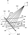
- FIG. 1 depicts an example system 100 according to example embodiments of the present disclosure.
- the system 100 can include a plurality of platforms 102A-G and a computing system 104.
- the platforms 102A-G and the computing system 104 can be configured to communicate with one another (e.g., to send and/or receive data).
- the platforms 102A-G can include a multi-function emitter platform, a remotely operated platform (ROAP), an unmanned vehicle (UAV), a helicopter, a drone, other aircraft, a watercraft, a vehicle capable of operating underwater, underwater platform, and/or any other device capable of sufficient maneuverability for the operations described herein.
- Each platform 102A-G of the plurality of platforms 102A-G can be physically separated from each of the other platforms 102A-G of the plurality of platforms 102A-G. For instance, in some implementations, no wires and/or other components need be configured to physically couple the plurality of platforms 102A-G to one another.
- Each of the platforms 102A-G can include one or more computing device(s).
- the computing device(s) can include various components for performing various operations and functions.
- the computing device(s) can include one or more processor(s) and one or more memory device(s).
- the one or more memory device(s) can store instructions that when executed by the one or more processor(s) cause the one or more processor(s) to perform the operations and functions for providing a synthetic track, as described herein.
- the computing system 104 can be associated with an entity that maintains, controls, monitors, and/or is otherwise associated with the operation of the platforms 102A-G.
- the computing system 104 can be associated with an operations and/or command center for the platforms 102A-G (e.g., a ground-based center, airborne control node, other control node).
- the computing system 104 can include one or more computing device(s) 106.
- the computing device(s) 106 can include various components for performing various operations and functions.
- the computing device(s) 106 can include one or more processor(s) and one or more memory device(s).
- the one or more memory device(s) can store instructions that when executed by the one or more processor(s) cause the one or more processor(s) to perform the operations and functions, as described herein.
- the computing device(s) 106 can be configured to coordinate the creation of a synthetic track 108, by at least some of the platforms 102A-G, that can be observed by one or more observation device(s) 110.
- the synthetic track 108 can be a false object travel path and/or a realistic implied vehicle path (or paths) that can be observable by the one or more observation device(s) 110.
- the synthetic track 108 can create an angular deception to mislead the observation device(s) 110 as to the actual location of one or more of the platforms 102A-G. For instance, a first angle 112 associated with the synthetic track 108 can be different than a plurality of second angles associated with the travel paths of the plurality of platforms 102A-G, as further described herein.
- the observation device(s) 110 can include a radar device, tracking device, monitoring device, anti-aircraft device, water associated device, etc. associated with an entity that the operators/controllers of the platforms 102A-G desire to mislead as to the location and/or travel paths of the platforms 102A-G.
- the observation device(s) 110 can be associated with an adverse and/or hostile entity/party.
- the observation device(s) 110 can be associated with an entity/party (e.g., non-hostile) that does not have permission, clearance, a need-to-know, etc. to know and/or identify the location and/or travel paths of the platforms 102A-G.
- the observation device(s) 110 can include one or more computing device(s) 114.
- the computing device(s) 114 can include various components for performing various operations and functions, such as recognizing a synthetic track as further described herein.
- the computing device(s) 106 can be configured to identify a travel path for each platform 102A-G of the plurality of platforms 102A-G.
- a travel path can be a flight path of an aerial platform, a travel path of a watercraft platform, a travel path of an underwater platform, a travel path of another platform type, etc.
- one or more of the platforms 102A-G of the plurality of platforms 102A-G can be associated with a travel path such that the respective platform 102A-G remains generally at a single location.
- FIG. 2 depicts an example orientation 200 of the plurality of platforms 102A-G.
- the travel paths 202A-G of each of the platforms 102A-G can be static, such that the respective platform 102A-G remains generally at a single location in the air.
- one or more of the platforms 102A-G can be associated with a non-static flight plan, such that the respective platform 102A-G travels from more than one location.
- FIG. 3 depicts an example orientation 300 of the plurality of platforms 102A-G.
- one or more platform 102A-G of the plurality of platforms 102A-G can be associated with a travel path 302A-G that includes a segment that is in a generally parallel direction relative to one or more travel paths of one or more other platforms 102A-G of the plurality of platforms 102A-G.
- one or more of the platforms 102 can be associated with an arbitrary travel path, such that the respective platform 102A-G travels from more than one location in an arbitrary direction relative to the other platforms.
- FIG. 4 depicts an example orientation 400 of the plurality of platforms 102A-G.
- one or more platform 102A-G of the plurality of platforms 102A-G can be associated with a travel path 402A-G that includes a segment that is in a generally arbitrary direction relative to one or more travel paths of one or more other platforms 102A-G of the plurality of platforms 102A-G.
- the computing device(s) 106 is configured to determine a location range 116 and/or a time range 118 for the synthetic track 108 to be created by the plurality of platforms 102A-G based, at least in part, on the travel path (e.g., 202A-G, 302A-G, 402A-G) for each platform. For instance, the computing device(s) 106 is configured to determine that it would like to create (e.g. create the appearance of) the synthetic track 108 within the location range 116. Additionally, and/or alternatively, the computing device(s) 106 is configured to determine that it would like to create (e.g. create the appearance of) the synthetic track 108 within the time range 118.
- Such determinations can be based, at least in part, for example, on the presence and/or location of the observation device(s) 110, a particular objective, etc.
- the computing device(s) 106 can examine the respective travel paths (e.g., 402A-G) of each of the platforms 102A-G and determine when and where each of the platforms 102A-G will be and at which point(s) in the travel paths (e.g., 402A-G) the platforms 102A-G should generate an emission such that the synthetic track 108 appears within the location range 116 and/or the time range 118.
- the computing device(s) 106 can determine the location range 116 and/or the time range 118 for the synthetic track 108 and send a command signal and/or travel path to the platforms 102A-G such that the platforms 102A-G are properly positioned to create (e.g. create the appearance of) the synthetic track 108 within the location range 116 and/or the time range 118.
- the computing device(s) 106 determine an emission location 120A-G and an emission time 122A-G for each platform 102A-G of the plurality of platforms 102A-G based, at least in part, on the location range 116 and/or the time range 118.
- the emission location is indicative of a location (e.g., p 1 ... p 7 ... p n ) at which the respective platform 102A-G is to generate an emission 126A-G.
- the emission time 122A-G is indicative of a time (e.g., t 1 . . . t 7 . . . t n ) at which the respective platform 102A-G is to generate an emission 126A-G.
- the computing device(s) 106 can determine that a first platform 102A should generate an emission 126A at the emission location 120A and the emission time 122A.
- the emission location 120A and the emission time 122A can be identified such that the emission 126A is generated to create at least a portion of the synthetic track 108 within the location range 116A and the time range 122A.
- This process can be repeated for each of the platforms 102A-G.
- the emission times 122A-G, for each of the platforms 102A-G can be separated by fixed time intervals. This can allow the synthetic track 108 to appear more realistic (e.g., similar to a real vehicle travel path) to the observation device(s) 110.
- the computing device(s) 106 can be configured to coordinate the creation of the synthetic track 108 by, for instance, sending a set of data 128A-G to each of the plurality of platforms 102A-G.
- Each respective set of data 128A-G can indicate the emission location 120A-G and/or the emission time 122A-G at which the respective platform 102A-G is to generate an emission 126A-G to create (at least a portion of) the synthetic track 108.
- the set of data 128A can indicate the emission location 120A (e.g., p 1 ) and/or the emission time 122A (e.g., t 1 ) at which the respective platform 120A is to generate the emission 126A, to create (at least a portion of) the synthetic track 108.
- the set of data 128A can include only the emission time 122A-G.
- each emission time 122A-G can be associated with a location in the travel path (e.g., 402A) of the respective platform (e.g., 102A) such that the emissions are generated within the location range 116.
- the platform 102A may only need to know when to generate the emission 126A as the location of the platform 102A can be pre-determined for each time along the travel path 402A.
- Each platform 102A-G of the plurality of platforms 102A-G is configured to receive a set of data 128A-G indicating an emission location 120A-G and/or an emission time 122A-G at which the platform 102A-G is to generate an emission 126A-G.
- the platforms 102A-G can receive the set of data 128A-G when one or more (or each) platform 102A-G of the plurality of platforms102A-G is deployed (e.g., travelling, airborne, underwater).
- the set of data 128A-G can be received by the platforms 102A-G before one or more (or each) of the platforms 102A-G are deployed. In this way, the computing device(s) 106 can pre-program the platforms 102A-G to create the synthetic track 108 within the location and/or time ranges 116, 118.
- Each platforms 102A-G is configured to generate an emission 126A-G at the emission location 120A-G and/or emission time 122A-G (e.g., indicated in the set of data 128A-G) such that at least a portion of the synthetic track 108 is created by the emissions 126A-G of the platform 102A-G within the location range 116 and/or time range 118.
- the emissions 126A-G can include a radio-frequency (RF) emission, a light emission, a sonar emission, and/or other types of emissions that can be observed and/or detected by the observation device(s) 110.
- Each emission 126A-G can be similar to the other emissions such that they appear, to the observation device(s) 110, to be generated by the same source.
- the emissions 126A-G can be separated by fixed time intervals. In this way, it can appear, to the observation devices 110, as if a platform is moving in the direction of the synthetic track 108, when in fact, no such platform exits.
- the emissions 126A-G can vary in reflectivity and/or emissivity from one another.
- the set of data 128A-G can be indicative of a reflectivity and/or emissivity associated at which a respective emission 126A-G is to be generated by the platform 102A-G.
- Each platform 102A-G can generate its respective emission based, at least in part, on the reflectivity and/or emissivity indicated in the set of data 128A-G.
- the reflectivity and/or emissivity associated with emission of a platform can be different than one or more reflectivity and/or emissivity associated with the emissions of other platforms. In this way, a location/time sequence of varying reflectivity and/or emissivity can be employed to provide further deception of the observation device(s) 110.
- the plurality of platforms 102A-G can generate the emissions 126A-G in a sequence based, at least in part, on the emission locations 120A-G and/or emission times 122A-G to create the synthetic track 108.
- a first platform 102A can be configured to generate a first emission 126A at a first emission location 120A (e.g., p 1 ) and/or at a first emission time 122B (e.g., t 1 ).
- the first emission 126A can be the first emission in the sequence.
- a second platform 102B can be configured to generate a second emission 126B at a second emission location 120B (e.g., p 2 ) and/or at a second emission time 122A (e.g., t 2 ). The second emission 126B can occur after the first emission 126A.
- a third platform 102C can be configured to generate a third emission 126C at a third emission location 120C (e.g., p 3 ) and/or at a third emission time 122C (e.g., t 3 ). The third emission 126C can occur after the second emission 126B.
- a fourth platform 102D can be configured to generate a fourth emission 126D at a fourth emission location 120D (e.g., p 4 ) and/or at a fourth emission time 122D (e.g., t 4 ).
- the fourth emission 126D can occur after the third emission 126C. This process can continue in a similar manner with a fifth platform 102E and sixth platform 102F.
- a seventh platform 102G can be configured to generate a seventh emission 126G at a seventh emission location 120G (e.g., p 7 ) and/or at a seventh emission time 122G (e.g., t 7 ).
- the seventh emission 126G can represent the last emission in the sequence although the present disclosure can include more or less numbers of emissions and/or platforms without deviating from the scope of the present disclosure.
- the first through seventh emissions 126A-G can be generated in the above-described sequence such that it appears that an platform is traveling along the synthetic track 108 and making periodic emissions.
- the synthetic track 108 created by the emissions 126A-G can be associated with a first angle 112 that is different than a plurality of second angles 404A-G associated with one or more travel paths 402A-B of the plurality of platforms 102A-G.
- the platforms 102A-G can be configured to create angular deception to mislead the observation device(s) 110 to determine that a false platform is traveling in a direction and/or angle that is different than the platforms 102A-G.
- the observed synthetic track 108 could match and be consistent with TDOA (time difference of arrival) data, if available.
- TDOA time difference of arrival
- some matches and/or mismatches can be created in an effort to exploit specific logic.
- observation device(s) 110 with matching synthetic tracks and TDOA data would find that frequency difference of arrival (FDOA) does not match the synthetic track 108 (unless emission frequencies were tailored as a function of angle, and would only work with good sidelobes or noise cover). This can arise because spatially separated FDOA receivers can observe differing Doppler shifts depending on the relative orientation to the apparent synthetic track 108.
- FDOA frequency difference of arrival
- the synthetic track 108 can create a mismatch from FDOA data because the synthetic track Doppler does not have the correct variation as a function angle from the synthetic track 108.
- the FDOA mismatch may be a positive or negative feature, depending on the victim systems and desired effect.
- creating conflicts in observation device(s) 110 may be sufficient to deceive the observation device(s) 110 or proper correlation among multiple observers. For example, if the platforms 120A-G are associated with arbitrary travel paths, they can still maintain a synthetic track aligned with TDOA and introduce substantial randomness into FDOA; if the FDOA confidence breaks down, there may be restored (false) confidence in the false arbitrarily synthetic (and TDOA) track.
- a burst of emissions 126A-G from each platform 102A-G can appear to create a series of false targets along the instantaneous radial from the platforms 102A-G to observation device(s) 110.
- the apparent formation orientation can differ between observation device(s) 110 and the formation orientation can rotate over time. Accordingly, the observation device(s) 110 can be misled as to the actual locations and/or travel paths of the platforms 102A-G.
- the emissions 126A-G can be generated not in response to one or more signal(s) from one or more observation device(s) 110.
- FIGS. 2-5 depict example implementations in which the emissions 126A-G are not generated in response to the plurality of platforms 102A-G receiving one or more signal(s) from one or more observation device(s) 110.
- one or more of the emissions 126A-G can be generated by one or more of the platform(s) 126A-G in response to one or more of the platforms 102A-G receiving one or more signal(s) from one or more observation device(s) 110.
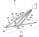
- FIG. 5 depicts an example orientation 500 of the plurality of platforms 102A-C.
- the platform(s) 102A-C can receive one or more signal(s) 502A-C from the observation device(s) 110.
- the signal(s) 502A-C can be encoded to induce a response from the platform(s) 102A-C to facilitate the monitoring of such platforms.
- one or more of the platform(s) 102A-C can be located at a position other than the emission location determined by the computing device(s) 106.
- the first platform 102A can be located at a position 502A (e.g., p 1 ') when it receives a first signal 502A (e.g., at a time t 1 '). If the first platform 102A responded immediately following receipt of the signal 502A (e.g., with the first platform 102A at a position p 1 ', at a time t 1 ') then the sequence of emissions may create a synthetic track that does not appear like that of real platform. This can lead to a risk of the observation device(s) 110 rejecting the synthetic track.
- one or more of the platforms 102A-C can be configured to determine a time delay and adjust its emission time such that the emissions appear to be generated within the location range 116 (at an appropriate time), in accordance with the planned sequence.
- the first platform 102A can be configured to receive the first signal 502A from the one or more observation device(s) 110.
- the first platform 102A can be configured to determine a time delay 506A (e.g., d 1 ) based, at least in part, on the signal 502A received from the one or more observation device(s) 110.
- the time delay 506A (e.g., d 1 ) can include the time necessary for the first emission 126A to appear as if it was generated from a position (e.g., p 1 ) within the location range 116.
- the first platform 102A can adjust its emission time based, at least in part, on the time delay 506A (e.g., d 1 ), such that the first emission 126A can be generated at the adjusted emission time 508A to create at least the portion of a synthetic track 108 (to appear) within the location range 116.
- the first platform 102A and/or the computing device(s) 106 can communicate with the second platform 102B, third platform 102C, etc. to inform the other platforms of the delay in one or more of the emissions, so that the other emission locations and/or times can be generated to create a synthetic track that will not be rejected by the observation device(s) 110.
- the time delay 506A can be indicative of a range at which the emission 126A can be generated.
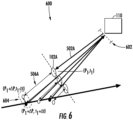
- FIG. 6 depicts an example orientation 600 of the plurality of platforms 102A-C.
- the first platform 102A can be configured to receive the first signal 502A from the one or more observation device(s) 110.
- the first platform 102A can determine an observational error 602 associated with the one or more observation device(s) 110 based, at least in part, on the signal 502A received from the one or more observation device(s) 110.
- the first platform 102A can determine the observational error 602 based, at least in part, on the transmitting power, the wavelength, the beam width, other characteristics, etc. associated with the signal 502A.
- the first platform 102A can be configured to determine the time delay 506A based, at least in part, on the observational error 602.
- the time delay 506A can be indicative of a range 604 at which the emission 126A can be generated.
- the range 604 can include an emission location range (e.g., p 1 - ⁇ p . . . p 1 + ⁇ p) and/or an emission time range (e.g., t 1 - ⁇ t . . . t 1 + ⁇ t) in which the first platform 102A can generate the emission 126A such that, at least a portion of, the synthetic track 108 will not be rejected by the observation device(s) 110.
- the synthetic track 108 does not have to be perfectly straight and/or include emissions 126A-G within perfectly segmented intervals. Rather, the first platform 102A can have a degree of freedom as to when and/or where it creates the first emission 126A in response to the first signal 502A, such that the synthetic track 108 will still be accepted by the observation device(s) 110.
- the range 604 can be indicative of such degree of freedom.
- the observation device(s) 110 can have a fairly wide angle association gate appropriate for the specific measurement errors, thus "imperfect angle" response emissions (e.g., creating the synthetic track) could be accepted and not recognized as unusual. If a time gap (e.g., between response emissions) is large compared to drop track criteria, additional response emissions could be included with proper timing but have an imperfect angle. Unless the individual travel paths of the platforms 102A-G are designed to mimic the proper cross range rate (of the synthetic track 108), there can be some error in the apparent cross range position. However, if these imperfect angles fell within the association gates of the observation device(s) 110 they could be accepted by the observation device(s) 110.
- time window can be designed to fall within the anticipated angle gate of the observation device(s) 110 (e.g., this can be approximately or exactly known and/or can be estimated given the beamwidth and SNR) with down-range time adjustments accounting for the differing trajectory between any individual platform 102A-G and the synthetic track 108.
- the time window could be viewed, for example, as a method to counter imperfect angular positioning of the first platform 102A.
- the platforms 102A-G can know its own effective radiated power, and thus, SNR estimation associated with observation device(s) 110 can be accomplished utilizing a priori/told-in positional information or localization techniques, such as TDOA measurements, from the platform 102A-G themselves.
- FIGS. 1-6 The number of components (e.g., platforms 102A-G, emissions 126A-G, synthetic track 108) shown in FIGS. 1-6 are not intended to be limiting.
- the systems and methods of the present disclosure can include more, less, and/or different components than shown in FIGS. 1-6 without deviating from the scope of the present disclosure.
- more than one synthetic track can be created by one or more of the platforms 102A-G.
- FIG. 7 depicts a flow diagram of an example method 700 for providing a synthetic track to one or more observation devices according to example embodiments of the present disclosure.
- FIG. 7 is implemented by one or more computing device(s) (e.g., the computing device(s) 106 depicted in FIGS. 1 and 9 ) as well as a plurality of platforms (e.g., the platforms 102A-G depicted in FIGS. 1-6 and 9 ).
- One or more step(s) of the method 700 can be performed while one or more (or each) of the platforms 102A-G are deployed.
- FIG. 7 depicts steps performed in a particular order for purposes of illustration and discussion.
- the method 700 includes determining a location range and/or a time range for a synthetic track.
- the computing device(s) 106 can determine a location range 116 and/or a time range 118 for a synthetic track 108 to be created by at least a subset of a plurality of platforms 102A-G. In some implementations, this can be based, at least in part, on the position, type, orientation, etc. of the one or more observation device(s) 110. In some implementations, this determination can be based, at least in part, on the travel path (e.g., 202A-G, 302A-G, 402A-G) for each platform 102A-G.
- the travel path e.g., 202A-G, 302A-G, 402A-G
- the synthetic track 108 can be a false object travel path that is observable by the one or more observation device(s) 110.
- the synthetic track 108 can create angular deception to mislead the observation device(s) 110.
- a first angle 112 associated with the synthetic track 108 can be different than a plurality of second angles (e.g., 404A-B) associated with one or more travel paths (e.g., 402A-G) of at least the subset of platforms 102A-G.
- the method 700 can include identifying a travel path for each platform of a plurality of platforms.
- the computing device(s) 106 can identify a travel path (e.g., 202A-G, 302A-G, 402A-G) for each platform 102A-G of at least the subset of platforms 102A-G. This can be done while one or more of at least the subset of platforms 102A-G are deployed (e.g., a swarm of airborne platforms) and/or before one or more of at least the subset of platforms 102A-G are deployed.
- a travel path e.g., 202A-G, 302A-G, 402A-G
- one or more platform(s) 102A-G of at least the subset of platforms 102A-G can be associated with one or more travel path(s) (e.g., 202A-G) that are static, such that the respective platform remains generally at a single location.
- one or more platform(s) 102A-G of at least the subset of platforms 102A-G can be associated with one or more travel path(s) (e.g., 302A-G) that include a segment that is in a generally parallel direction relative to the travel paths (e.g., 302A-G) of one or more other platform(s) 102A-G of at least the subset of platforms 102A-G.
- one or more platform(s) 102A-G of at least the subset of platforms 102A-G can be associated with one or more travel path(s) (e.g., 402A-G) that include a segment that is in a generally arbitrary direction relative to one or more travel path(s) (e.g., 402A-G) of one or more other platform(s) 102A-G of at least the subset of platforms 102A-G.
- travel path(s) e.g., 402A-G
- the method 700 includes determining an emission location and emission time for each of the platforms of at least the subset of the plurality of platforms.
- the computing device(s) 106 can determine an emission location 120A-G and/or an emission time 122A-G for each of the platforms 102A-G of at least the subset of platforms 102A-G based, at least in part, on the location range 116 and/or the time range 118.
- the emission location 120A-G can be indicative of a location at which the respective platform 102A-G is to generate an emission 126A-G.
- the emission time 122A-G can be indicative of a time at which the respective platform 102A-G is to generate the emission 126A-G.
- the emission time 122A-G can be separated by fixed time intervals.
- the method 700 includes sending a set of data to each of the plurality of platforms.
- the computing device(s) 106 can send a set of data 128A-G to each of platform of at least a subset of the plurality of platforms 102A-G.
- Each respective set of data 128A-G can indicate the emission location 120A-G and/or the emission time 122A-G at which the respective platform 102A-G is to generate the emission 126A-G to create the synthetic track 108.
- the computing device(s) 106 can coordinate the platforms 102A-G such that at least the subset of platforms 102A-G are to generate the emissions 126A-G in a sequence based, at least in part, on the emission locations 120A-G and/or the emission times 122A-G to create the synthetic track 108 within the location range 116 and/or the time range 118.
- the set of data 128A-G can also, and/or alternatively, include a travel path for the platform 102A-G to follow.
- the method 700 can include receiving the set of data.
- each platform 102A-G (e.g., of at least a subset of the plurality of platforms) can receive the set of data 128A-G indicating the emission location 120A-G, the emission time 122A-G, and/or a travel path at which the respective platform 102A-G is to generate the emission 126A-G.
- At least the subset of platforms 102A-G can receive the sets of data 128A-G while airborne and/or while grounded (e.g., before deployment).
- each platform 102A-G of the plurality of platforms 102A-G (and/or subset) can be physically separated from each of the other platforms 102A-G of the plurality of platforms 102A-G (and/or subset).
- platforms 102A-G can travel according to a prescribed flight path.
- the flight path can allow at least the platforms 102A-G to be properly positioned to make an emission 126A_G at the emission location 120A-G and/or the emission time 122A-G.
- the method 700 can include receiving a signal from the one or more observation devices.
- at least a subset of platforms 102A-G can receive one or more signals 502A-C from the one or more observation device(s) 110.
- the signal(s) 502A-C can be encoded to induce a response from the subset of platform(s) 102A-C to facilitate the monitoring of such platforms by the observation device(s) 110.
- the method 700 can include determining an observational error associated with the one or more observation devices. For instance, at least the subset of platforms 102A-G can determine an observational error 602 associated with the one or more observation device(s) 110 based, at least in part, on the one or more signal(s) 502A-C received from the one or more observation device(s) 110.
- the first platform 102A can determine the observational error 602 based, at least in part, on the transmitting power, the wavelength, the beam width, other characteristics, etc. associated with the signal 502A.
- the method 700 can include determining a time delay based, at least in part, on the signal received from the one or more observation device(s). For instance, one or more of the subset of platforms 102A-G can determine a time delay (e.g., 506A) based, at least in part, on the signal (e.g., 502A) received from the one or more observation device(s) 110. As described above, the time delay 506A can include the time necessary for the first emission 126A to appear as if it was generated from a position (e.g., p 1 ) within the location range 116.
- a position e.g., p 1
- the time delay (e.g., 506A) can be based, at least in part, on the observational error 602.
- the time delay 506A can be indicative of a range 604 at which the emission 126A can be generated.
- the platforms 102A-G can leverage the observational error 602 of the observation device(s) 110 such that the synthetic track is less likely to be rejected by the observation device(s) 110, as described above.
- the method 700 can include adjusting the emission time.
- one or more of the subset of platforms 102A-G can adjust the emission time 122A-G (and/or the emission location 120A-G) based, at least in part, on the time delay (e.g., 506A), such that the emission 126A-G is generated at the adjusted emission time (e.g., 508A) to create the appearance that at least a portion of the synthetic track 108 is within the location range 116.
- the time delay e.g., 506A
- the emission 126A-G is generated at the adjusted emission time (e.g., 508A) to create the appearance that at least a portion of the synthetic track 108 is within the location range 116.
- One of more of at least the subset of platform(s) 102A-G can delay the emission time (e.g., 508A) at which the respective platform 102A-G is to generate the emission 126A-G, such that the synthetic track 108 is created at (e.g. appears to be created at) the location range 116.
- the emission time e.g., 508A
- the synthetic track 108 is created at (e.g. appears to be created at) the location range 116.
- the method 700 can include generating the emission.
- each platform 102A-G of at least the subset of platforms can generate an emission 126A-G at the emission time 122A-G (and/or emission location 120A-G) such that at least a portion of a synthetic track 108 is created by the emission 126A-G of the platform 102A-G within a location range 116 (and/or the time range 118).
- the synthetic track 108 can be observable by one or more observation device(s) 110.
- the emissions 126A-G are to be generated by at least the subset of platforms 102A-G in response to one or more of at least the subset of platforms 102A-G receiving one or more signals 502A-C from one or more observation device(s) 110, in accordance with (714)-(720) (e.g. at an adjusted emission time).
- the emissions 126A-G are not generated in response to at least the subset of platforms 102A-G receiving one or more signals 502A-C from the one or more observation device(s) 110.
- FIG. 8 depicts a flow diagram of an example method 800 for identifying a synthetic track according to an example not being part of the present invention.
- FIG. 8 can be implemented by one or more computing device(s), such as the computing device(s) 114 of the observation device(s) 110, depicted in FIGS. 1 and 9 .
- One or more step(s) of the method 800 can be performed while one or more (or each) of the platforms 102A-G are deployed (e.g., travelling, underwater, airborne).
- FIG. 8 depicts steps performed in a particular order for purposes of illustration and discussion.
- the method 800 can include receiving emissions creating a synthetic track.
- the computing device(s) 114 of the observation device(s) 110 can receive, detect, observe, etc. the emissions 126A-G intended to create the synthetic track 108 from one more platforms 102A-G.
- the computing device(s) 114 can include a receiver that can be configured to receive, detect, observe, etc. the emissions 126A-G.
- the computing device(s) 114 can determine if the emissions 126A-G meet one or more initial association gates of the observation device(s) 110.
- the method 800 can include whether an irregularity exists.
- the computing device(s) 114 of the observation device(s) 110 can determine whether an irregularity associated with the synthetic track 108 exists based, at least in part, on one or more of the emissions 126A-G.
- the computing device(s) 114 can examine the emissions 126A-G to determine if any short term angle deviations exist in the synthetic track 108.
- the short term angle deviations can appear as short term angle slow down and/or speed up with respect to the synthetic track 108. This can occur, for instance, when one or more platforms 102A-G generate emissions within a range (e.g., 604) - creating a synthetic track 108 that can include short term angle deviations.
- This examination can occur before and/or after the computing device(s) 114 determine if the emissions 126A-G meet one or more initial association gates of the observation device(s) 110. In the event that enough short term angle deviations are found (e.g., beyond a threshold level) the computing device(s) 114 can determine that an irregularity associated with the synthetic track 108 exists.
- the method 800 can include rejecting the synthetic track.
- the computing device(s) 114 of the observation device(s) 110 can reject the synthetic track 108 in the event that an irregularity associated with the synthetic track 108 exists.
- the method 800 can include accepting the synthetic track.
- the computing device(s) 114 of the observation device(s) 110 can accept the synthetic track 108 in the event that a substantial irregularity associated with the synthetic track 108 does not exist.
- FIG. 9 depicts an example system 900 according to example embodiments of the present disclosure.
- the system 900 can include the computing system 104, the platforms 102A-G, which can be configured to communicate via the network 910, such as, a very high frequency (VHF) network, high frequency (HF) network, SATCOM network, WiFi network, and/or any other suitable communication network.
- the platforms 102A-G can be located at a remote location that is separated and remote from the computing system 104.
- the computing system 104 can be associated with a ground-based operation and/or command center and the platforms 102A-G can be deployed (e.g., airborne, travelling in water, underwater).
- the system 900 can include the observation device(s) 110.
- the computing system 104 can include one or more computing device(s) 106.
- the computing device(s) 106 can include one or more processor(s) 106A and one or more memory device(s) 106B.
- the one or more processor(s) 106A can include any suitable processing device, such as a microprocessor, microcontroller, integrated circuit, logic device, and/or other suitable processing device.
- the one or more memory device(s) 106B can include one or more computer-readable media, including, but not limited to, non-transitory computer-readable media, RAM, ROM, hard drives, flash drives, and/or other memory devices.
- the one or more memory device(s) 106B can store information accessible by the one or more processor(s) 106A, including computer-readable instructions 106C that can be executed by the one or more processor(s) 106A.
- the instructions 106C can be any set of instructions that when executed by the one or more processor(s) 106A, cause the one or more processor(s) 106A to perform operations.
- the instructions 106C can be executed by the one or more processor(s) 106A to cause the one or more processor(s) 106A to perform operations, such as any of the operations and functions for which the computing system 104 and/or the computing device(s) 106 are configured, the operations for providing a synthetic track to one or more observation device(s) (e.g., method 700), as described herein, and/or any other operations or functions of the one or more computing device(s) 106.
- the instructions 106C can be software written in any suitable programming language or can be implemented in hardware. Additionally, and/or alternatively, the instructions 106C can be executed in logically and/or virtually separate threads on processor(s) 106A.
- the memory device(s) 106B can further store data 106D that can be accessed by the processors 106A.
- the data 106D can include data and/or information associated with the location range 116, the time range 118, the emission locations 120A-G, the emission times 122A-G, the sets of data 128A-G, the travel paths of the platforms 102A-G, data and/or information associated with the platforms 102A-G, data and/or information associated with the observation device(s) 110, and/or any other data and/or information described herein.
- the computing device(s) 106 can also include a communication interface 106E used to communicate, for example, with the other components of system 900 (e.g., via network 910).
- the communication interface 106E can include any suitable components for interfacing with one or more network(s), including for example, transmitters, receivers, ports, controllers, antennas, and/or other suitable components.
- the platforms 102A-G can include one or more computing device(s) 902.
- the computing device(s) 902 can include one or more processor(s) 902A and one or more memory device(s) 902B.
- the one or more processor(s) 902A can include any suitable processing device, such as a microprocessor, microcontroller, integrated circuit, logic device, and/or other suitable processing device.
- the one or more memory device(s) 902B can include one or more computer-readable media, including, but not limited to, non-transitory computer-readable media, RAM, ROM, hard drives, flash drives, and/or other memory devices.
- the one or more memory device(s) 902B can store information accessible by the one or more processor(s) 902A, including computer-readable instructions 902C that can be executed by the one or more processor(s) 902A.
- the instructions 902C can be any set of instructions that when executed by the one or more processor(s) 902A, cause the one or more processor(s) 902A to perform operations.
- the instructions 902C can be executed by the one or more processor(s) 902A to cause the one or more processor(s) 902A to perform operations, such as any of the operations and functions for which the platforms 102A-G and/or the computing device(s) 902 are configured, the operations for providing a synthetic track to one or more observation device(s) (e.g., method 700), as described herein, and/or any other operations or functions of the platforms 102A-G.
- the instructions 902C can be software written in any suitable programming language or can be implemented in hardware. Additionally, and/or alternatively, the instructions 902C can be executed in logically and/or virtually separate threads on processor(s) 902A.
- the memory device(s) 902B can further store data 902D that can be accessed by the processors 902A.
- the data 902D can include data and/or information associated with the location range 116, the time range 118, the emission locations 120A-G, the emission times 122A-G, the sets of data 128A-G, the travel paths of the platforms 102A-G, data and/or information associated with the computing system 104, data and/or information associated with the platforms 102A-G, data and/or information associated with the observation device(s) 110, and/or any other data and/or information described herein.
- the computing device(s) 902 can also include a communication interface 902E used to communicate, for example, with the other components of system 900.
- the communication interface 902E can be used to communicate with the computing device(s) 106 via the network(s) 910. Additionally, and/or alternatively, the communication interface 902E can be configured to generate the emissions 126A-G.
- the communication interface 902E can include any suitable components for interfacing with the one or more network(s) 910 and/or any suitable components for generating the emissions 126A-G, including for example, transmitters, receivers, ports, controllers, antennas, and/or other suitable components.
- the observation device(s) 110 can include one or more computing device(s) 114.
- the computing device(s) 114 can include one or more processor(s) 114A and one or more memory device(s) 114B.
- the one or more processor(s) 114A can include any suitable processing device, such as a microprocessor, microcontroller, integrated circuit, logic device, and/or other suitable processing device.
- the one or more memory device(s) 114B can include one or more computer-readable media, including, but not limited to, non-transitory computer-readable media, RAM, ROM, hard drives, flash drives, and/or other memory devices.
- the one or more memory device(s) 114B can store information accessible by the one or more processor(s) 114A, including computer-readable instructions 114C that can be executed by the one or more processor(s) 114A.
- the instructions 114C can be any set of instructions that when executed by the one or more processor(s) 114A, cause the one or more processor(s) 114A to perform operations.
- the instructions 114C can be executed by the one or more processor(s) 114A to cause the one or more processor(s) 114A to perform operations, such as any of the operations and functions for which the observation device(s) 110 and/or the computing device(s) 114 are configured, the operations for identifying a synthetic track (e.g., method 800), as described herein, and/or any other operations or functions of the one or more observation device(s) 110.
- the instructions 114C can be software written in any suitable programming language or can be implemented in hardware. Additionally, and/or alternatively, the instructions 114C can be executed in logically and/or virtually separate threads on processor(s) 114A.
- the memory device(s) 114B can further store data 114D that can be accessed by the processors 114A.
- the data 114D can include data and/or information associated with the emissions 126A-G, data associated with the synthetic track 108 (e.g., irregularities, deviations), data and/or information associated with the platforms 102A-G, and/or any other data and/or information described herein.
- the computing device(s) 114 can also include a communication interface 114E.
- the communication interface 114E can be used to send signals 502A-C to the platforms 102A-G and/or receive, detect, monitor, observe, etc. emissions 126A-G.
- the communication interface 114E can include any suitable components for sending and receiving signals and/or emissions, including for example, transmitters, receivers, ports, controllers, antennas, and/or other suitable components.
Landscapes
- Engineering & Computer Science (AREA)
- Radar, Positioning & Navigation (AREA)
- Remote Sensing (AREA)
- Physics & Mathematics (AREA)
- General Physics & Mathematics (AREA)
- Computer Networks & Wireless Communication (AREA)
- General Engineering & Computer Science (AREA)
- Theoretical Computer Science (AREA)
- Signal Processing (AREA)
- Automation & Control Theory (AREA)
- Radar Systems Or Details Thereof (AREA)
- Traffic Control Systems (AREA)
Claims (13)
- Computerimplementiertes Verfahren (700) zum Bereitstellen einer synthetischen Bahn (108) für eine oder mehrere Beobachtungsvorrichtungen (110), umfassend:Bestimmen (702) eines Standortbereichs (116) und eines Zeitbereichs (118) durch ein oder mehrere Rechenvorrichtungen (104), damit eine synthetische Bahn (108) von mindestens einer Teilmenge einer Vielzahl von Plattformen (102A-G) erstellt wird;Bestimmen (706) eines Emissionsstandorts (120A-G) und einer Emissionszeit (122A-G) durch die eine oder mehreren Rechenvorrichtungen (104) für mindestens die Teilmenge von Plattformen der Vielzahl von Plattformen (102A-G), basierend mindestens teilweise auf dem Standortbereich (116) und dem Zeitbereich (118), wobei der Emissionsstandort (120A-G) einen Ort anzeigt, an dem die jeweilige Plattform eine Emission (126A-G) erzeugen soll, und die Emissionszeit (122A-G) einen Zeitpunkt anzeigt, zu dem die jeweilige Plattform die Emission (126A-G) erzeugen soll; undSenden (708) eines Datensatzes (128A-G) durch die eine oder mehreren Rechenvorrichtungen (104) an jede der Plattformen von mindestens der Teilmenge von Plattformen (102A-G), wobei jeder jeweilige Datensatz (128A-G) den Emissionsstandort (120A-G) und die Emissionszeit (122A-G) angibt, zu der die jeweilige Plattform die Emission erzeugen soll, um die synthetische Bahn (108) zu erstellen; dadurch gekennzeichnet, dassdie Emissionen (126A-G) nicht als Reaktion darauf erzeugt werden, dass die Plattformen (102A-G) ein oder mehrere Signale von einer oder mehreren Beobachtungsvorrichtungen (110) empfangen.
- Computerimplementiertes Verfahren (700) nach Anspruch 1, wobei mindestens die Teilmenge von Plattformen die Emissionen (126A-G) in einer Sequenz erzeugen soll, die mindestens teilweise auf den Emissionsstandorten (120A-G) und den Emissionszeiten (122A-G) basiert, um die synthetische Bahn (108) innerhalb des Standortbereichs (120A-G) und des Zeitbereichs (122A-G) zu erstellen.
- Computerimplementiertes Verfahren (700) nach Anspruch 1 oder 2, wobei die synthetische Bahn (108) ein falscher Objektfahrweg ist, der durch ein oder mehrere Beobachtungsvorrichtungen (110) beobachtbar ist.
- Computerimplementiertes Verfahren (700) nach einem der vorstehenden Ansprüche, wobei ein erster Neigungswinkel der synthetischen Fahrbahn (108) sich von einer Vielzahl zweiter Neigungswinkel eines oder mehrerer Fahrwege von mindestens der Teilmenge von Plattformen (102A-G) unterscheidet.
- Computerimplementiertes Verfahren (700) nach einem der vorstehenden Ansprüche, wobei jede Plattform der Vielzahl von Plattformen (102A-G) von jeder der anderen Plattformen der Vielzahl von Plattformen (102A-G) physisch getrennt ist.
- Computerimplementiertes Verfahren (700) nach einem der vorstehenden Ansprüche, wobei eine oder mehrere Plattformen mindestens der Teilmenge von Plattformen einem oder mehreren Fahrwegen (202A-G, 302A-G, 402A-G) zugeordnet sind, die ein Segment umfassen, das in einer im Allgemeinen parallelen Richtung relativ zu einem oder mehreren Fahrwegen einer oder mehrerer anderer Plattformen mindestens der Teilmenge von Plattformen liegt.
- Computerimplementiertes Verfahren (700) nach einem der vorstehenden Ansprüche, wobei eine oder mehrere Plattformen mindestens der Teilmenge von Plattformen einem oder mehreren Fahrwegen (202A-G, 302A-G, 402A-G) zugeordnet sind, die ein Segment umfassen, das in einer im Allgemeinen beliebigen Richtung relativ zu einem oder mehreren Fahrwegen einer oder mehrerer anderer Plattformen mindestens der Teilmenge von Plattformen liegt.
- Computerimplementiertes Verfahren (700) nach einem der vorstehenden Ansprüche, wobei eine oder mehrere Plattformen mindestens der Teilmenge von Plattformen einem oder mehreren Fahrwegen (202A-G, 302A-G, 402A-G) derart zugeordnet sind, dass die jeweilige Plattform im Allgemeinen an einem einzigen Standort verbleibt.
- Computerimplementiertes Verfahren (700) nach einem der vorstehenden Ansprüche, wobei die Emissionszeitpunkte (122A-G) durch feste Zeitintervalle getrennt sind.
- Rechensystem (104) zum Bereitstellen einer synthetischen Bahn (108) an eine oder mehrere Beobachtungsvorrichtungen (110), wobei das System (104) einen oder mehrere Prozessoren und eine oder mehrere Speichervorrichtungen umfasst, wobei die eine oder die mehreren Speichervorrichtungen Anweisungen speichern, die, wenn sie durch den einen oder die mehreren Prozessoren ausgeführt werden, den einen oder die mehreren Prozessoren veranlassen zum:Identifizieren eines Fahrwegs für jede Luftplattform von mindestens einer Teilmenge einer Vielzahl von Luftplattformen;Bestimmen eines Standortbereichs (116) und eines Zeitbereichs (118) für die synthetische Bahn (108), die von mindestens der Teilmenge der Vielzahl von Luftplattformen erstellt werden soll, basierend mindestens teilweise auf dem Fahrweg für jede Luftplattform;Bestimmen einer Emissionszeit (122A-G) für jede Luftplattform von mindestens der Teilmenge von Luftplattformen basierend mindestens teilweise auf dem Standortbereich (116) und dem Zeitbereich (118), wobei die Emissionszeit (122A-G) einen Zeitpunkt angibt, zu dem die jeweilige Luftplattform eine Emission (126A-G) erzeugen soll; undSenden eines Datensatzes (128A-G) an jede von mindestens der Teilmenge von Luftplattformen, wobei jeder jeweilige Datensatz (128A-G) die Emissionszeit (122A-G) angibt, zu der die jeweilige Luftplattform die Emission (126A-G) erzeugen soll,wobei mindestens die Teilmenge der Luftplattformen die Emissionen (126A-G) in einer Sequenz erzeugen soll, die mindestens teilweise auf den Emissionszeiten (122A-G) basiert, um die synthetische Bahn (108) zu erstellen; dadurch gekennzeichnet, dassdie Emissionen (126A-G) nicht als Reaktion darauf erzeugt werden, dass die Luftplattformen ein oder mehrere Signale von einer oder mehreren Beobachtungsvorrichtungen (110) empfangen.
- System (100) nach Anspruch 10, wobei die synthetische Bahn (108) ein falscher Objektfahrweg ist, der durch eine oder mehrere Beobachtungsvorrichtungen (110) beobachtbar ist, und wobei ein erster Winkel (112), der mit der synthetischen Bahn (108) verknüpft ist, sich von einer Vielzahl von zweiten Winkeln (404A-G) unterscheidet, die mit den Fahrwegen von mindestens der Teilmenge von Luftplattformen verknüpft sind.
- System (100) nach Anspruch 10 oder 11, wobei sich jede Plattform von mindestens der Teilmenge von Luftplattformen in der Luft befindet, und wobei jeder Emissionszeitpunkt (122A-G) mit einem Standort im Fahrweg der jeweiligen Luftplattform verknüpft ist, so dass die Emissionen (126A-G) innerhalb des Standortbereichs (116) erzeugt werden.
- System (100) zum Bereitstellen einer synthetischen Bahn (108) für eine oder mehrere Beobachtungsvorrichtungen (110), das System umfassend:
eine Vielzahl von Plattformen (102A-G), wobei jede Plattform von mindestens einer Teilmenge der Vielzahl von Plattformen (102A-G) einen oder mehrere Prozessoren und eine oder mehrere Speichervorrichtungen umfasst, wobei die eine oder die mehreren Speichervorrichtungen Anweisungen speichern, die, wenn sie von dem einen oder den mehreren Prozessoren ausgeführt werden, den einen oder die mehreren Prozessoren veranlassen zum:Empfangen eines Datensatzes (128A-G), der eine Emissionszeit (122AG) angibt, zu der die Plattform eine Emission (126A-G) erzeugen soll; undErzeugen der Emission (126A-G) zum Emissionszeitpunkt (122A-G), so dass durch die Emission (126A-G) der Plattform (102A-G) innerhalb eines Standortbereichs (118) mindestens ein Abschnitt einer synthetischen Bahn (108) erzeugt wird, wobei die synthetische Bahn (108) durch eine oder mehrere Beobachtungsvorrichtungen (110) beobachtbar ist;dadurch gekennzeichnet, dass die Emissionen (126A-G) nicht als Reaktion darauf erzeugt werden, dass die Plattformen (102A-G) ein oder mehrere Signale von einer oder mehreren Beobachtungsvorrichtungen (110) empfangen.
Priority Applications (1)
| Application Number | Priority Date | Filing Date | Title |
|---|---|---|---|
| EP25155222.0A EP4524616A3 (de) | 2016-07-01 | 2017-06-30 | Mehrplattformstandorttäuschungssystem |
Applications Claiming Priority (1)
| Application Number | Priority Date | Filing Date | Title |
|---|---|---|---|
| US15/200,513 US10277356B2 (en) | 2016-07-01 | 2016-07-01 | Multi-platform location deception system |
Related Child Applications (2)
| Application Number | Title | Priority Date | Filing Date |
|---|---|---|---|
| EP25155222.0A Division EP4524616A3 (de) | 2016-07-01 | 2017-06-30 | Mehrplattformstandorttäuschungssystem |
| EP25155222.0A Division-Into EP4524616A3 (de) | 2016-07-01 | 2017-06-30 | Mehrplattformstandorttäuschungssystem |
Publications (2)
| Publication Number | Publication Date |
|---|---|
| EP3264129A1 EP3264129A1 (de) | 2018-01-03 |
| EP3264129B1 true EP3264129B1 (de) | 2025-03-12 |
Family
ID=59312994
Family Applications (2)
| Application Number | Title | Priority Date | Filing Date |
|---|---|---|---|
| EP25155222.0A Pending EP4524616A3 (de) | 2016-07-01 | 2017-06-30 | Mehrplattformstandorttäuschungssystem |
| EP17178994.4A Active EP3264129B1 (de) | 2016-07-01 | 2017-06-30 | Mehrfachplattformstandorttäuschungssystem |
Family Applications Before (1)
| Application Number | Title | Priority Date | Filing Date |
|---|---|---|---|
| EP25155222.0A Pending EP4524616A3 (de) | 2016-07-01 | 2017-06-30 | Mehrplattformstandorttäuschungssystem |
Country Status (3)
| Country | Link |
|---|---|
| US (1) | US10277356B2 (de) |
| EP (2) | EP4524616A3 (de) |
| CA (1) | CA2972083A1 (de) |
Families Citing this family (3)
| Publication number | Priority date | Publication date | Assignee | Title |
|---|---|---|---|---|
| US10393860B2 (en) | 2016-07-01 | 2019-08-27 | General Electric Company | Multi-platform location deception detection system |
| US11476969B1 (en) * | 2020-03-23 | 2022-10-18 | Bae Systems Information And Electronic Systems Integration Inc. | Radio frequency deception network |
| CN112307633B (zh) * | 2020-11-03 | 2022-10-04 | 清源智翔(重庆)科技有限公司 | 多站时频差变参量迭代定位方法及系统 |
Family Cites Families (20)
| Publication number | Priority date | Publication date | Assignee | Title |
|---|---|---|---|---|
| US3504366A (en) | 1955-11-08 | 1970-03-31 | Us Navy | Means for producing range and angle deception of automatic tracking radar |
| US6707052B1 (en) | 1963-02-07 | 2004-03-16 | Norman R. Wild | Infrared deception countermeasure system |
| US5260820A (en) | 1991-05-14 | 1993-11-09 | Bull James G | Airborne fiber optic decoy architecture |
| US5136295A (en) | 1991-05-14 | 1992-08-04 | The Boeing Company | Airborne fiber optic decoy architecture |
| US5294930A (en) | 1992-05-01 | 1994-03-15 | Li Ming Chiang | Optical RF stereo |
| US6825791B2 (en) | 2002-12-20 | 2004-11-30 | Sanders Design International, Inc. | Deceptive signature broadcast system for aircraft |
| US6697008B1 (en) | 2003-02-28 | 2004-02-24 | Rockwell Collins, Inc. | Distributed electronic warfare system |
| US6910657B2 (en) * | 2003-05-30 | 2005-06-28 | Raytheon Company | System and method for locating a target and guiding a vehicle toward the target |
| IL156739A0 (en) * | 2003-07-02 | 2009-02-11 | Elta Systems Ltd | Method and system for destroying rockets |
| US6816109B1 (en) * | 2003-08-04 | 2004-11-09 | Northrop Grumman Corporation | Method for automatic association of moving target indications from entities traveling along known route |
| US7402818B2 (en) | 2005-02-02 | 2008-07-22 | Flight Safety Technologies, Inc | Tactical integrated illumination countermeasure system |
| US7333050B2 (en) * | 2005-03-01 | 2008-02-19 | The Boeing Company | Radio frequency signature augmentation system |
| IL172267A0 (en) | 2005-11-30 | 2006-04-10 | Elta Systems Ltd | A method and system for locating an unknown emitter |
| KR100916970B1 (ko) | 2007-11-19 | 2009-09-14 | 국방과학연구소 | 능동 rf 기만기 시뮬레이션 장치 |
| US8643719B2 (en) * | 2008-02-29 | 2014-02-04 | The Boeing Company | Traffic and security monitoring system and method |
| US8379967B1 (en) | 2008-12-04 | 2013-02-19 | Lockheed Martin Corporation | Swarm control systems and methods |
| IT1398102B1 (it) | 2009-06-26 | 2013-02-07 | Sie Soc It Elettronica | Metodo e apparecchiatura per la generazione di segnali di inganno angolare |
| US8615190B2 (en) | 2011-05-31 | 2013-12-24 | Exelis Inc. | System and method for allocating jamming energy based on three-dimensional geolocation of emitters |
| US9273965B2 (en) * | 2014-02-03 | 2016-03-01 | Raytheon Company | Method for determining future position boundary for a moving object from location estimates |
| US9696418B2 (en) * | 2015-05-04 | 2017-07-04 | Propagation Research Associates, Inc. | Systems, methods and computer-readable media for improving platform guidance or navigation using uniquely coded signals |
-
2016
- 2016-07-01 US US15/200,513 patent/US10277356B2/en active Active
-
2017
- 2017-06-29 CA CA2972083A patent/CA2972083A1/en not_active Abandoned
- 2017-06-30 EP EP25155222.0A patent/EP4524616A3/de active Pending
- 2017-06-30 EP EP17178994.4A patent/EP3264129B1/de active Active
Non-Patent Citations (2)
| Title |
|---|
| PURVIS K B ET AL: "Estimation and Optimal Configurations for Localization Using Cooperative UAVs", IEEE TRANSACTIONS ON CONTROL SYSTEMS TECHNOLOGY, IEEE SERVICE CENTER, NEW YORK, NY, US, vol. 16, no. 5, 1 September 2008 (2008-09-01), pages 947 - 958, XP011225894, ISSN: 1063-6536, DOI: 10.1109/TCST.2007.916348 * |
| YUNJUN XU ET AL: "Virtual motion camouflage based phantom track generation through cooperative electronic combat air vehicles", AUTOMATICA, vol. 46, no. 9, 1 September 2010 (2010-09-01), AMSTERDAM, NL, pages 1454 - 1461, XP055424207, ISSN: 0005-1098, DOI: 10.1016/j.automatica.2010.05.027 * |
Also Published As
| Publication number | Publication date |
|---|---|
| US20180006760A1 (en) | 2018-01-04 |
| EP4524616A3 (de) | 2025-06-18 |
| CA2972083A1 (en) | 2018-01-01 |
| US10277356B2 (en) | 2019-04-30 |
| EP3264129A1 (de) | 2018-01-03 |
| EP4524616A2 (de) | 2025-03-19 |
Similar Documents
| Publication | Publication Date | Title |
|---|---|---|
| EP3983822B1 (de) | Multistatisches radarsystem und betriebsverfahren dafür zur detektion und verfolgung von sich bewegenden zielen, insbesondere unbemannten luftfahrzeugen | |
| Khan et al. | On the detection of unauthorized drones—Techniques and future perspectives: A review | |
| Jansen et al. | Crowd-GPS-Sec: Leveraging crowdsourcing to detect and localize GPS spoofing attacks | |
| US12387608B1 (en) | Unmanned vehicle recognition and threat management | |
| US20200162489A1 (en) | Security event detection and threat assessment | |
| US12061485B2 (en) | Method and apparatus for ensuring aviation safety in the presence of ownship aircraft | |
| Mykytyn et al. | GPS-spoofing attack detection mechanism for UAV swarms | |
| US8990002B1 (en) | Method and apparatus for determining the relative position of a target | |
| US20200307787A1 (en) | Intelligent location awareness for unmanned systems | |
| EP3264129B1 (de) | Mehrfachplattformstandorttäuschungssystem | |
| Yasmine et al. | Survey on current anti-drone systems: process, technologies, and algorithms | |
| US11320532B2 (en) | Coordinated detecting of objects in an airspace | |
| EP3264649B1 (de) | Mehrfachplattformstandorttäuschungserkennungssystem | |
| US20190383923A1 (en) | Coordinated Searching Of An Airspace | |
| WO2022172217A1 (en) | System and method for rogue drone detection and interception | |
| US20250067867A1 (en) | Smart surveillance data processing systems for safe uncrewed aircraft and surface vessel operation beyond visual line of sight | |
| Adesina et al. | Aircraft location prediction using deep learning | |
| US20230053158A1 (en) | Avionics-free global aviation surveillance systems and processes | |
| US7551120B1 (en) | Method and a system for filtering tracks originating from several sources and intended for several clients to which they are supplied | |
| RU2837696C1 (ru) | Способ радиоэлектронного мониторинга и активного радиоэлектронного противодействия | |
| RU2809997C1 (ru) | Система обнаружения и противодействия беспилотным воздушным судам | |
| KR102550145B1 (ko) | 무인이동체 위성항법 유도 장치 및 방법 | |
| Castrillo et al. | A Review of Counter-UAS Technologies for Cooperative Defensive Teams of Drones. Drones 2022, 6, 65 | |
| GB2607615A (en) | Unmanned aerial vehicle detector |
Legal Events
| Date | Code | Title | Description |
|---|---|---|---|
| PUAI | Public reference made under article 153(3) epc to a published international application that has entered the european phase |
Free format text: ORIGINAL CODE: 0009012 |
|
| STAA | Information on the status of an ep patent application or granted ep patent |
Free format text: STATUS: THE APPLICATION HAS BEEN PUBLISHED |
|
| AK | Designated contracting states |
Kind code of ref document: A1 Designated state(s): AL AT BE BG CH CY CZ DE DK EE ES FI FR GB GR HR HU IE IS IT LI LT LU LV MC MK MT NL NO PL PT RO RS SE SI SK SM TR |
|
| AX | Request for extension of the european patent |
Extension state: BA ME |
|
| STAA | Information on the status of an ep patent application or granted ep patent |
Free format text: STATUS: REQUEST FOR EXAMINATION WAS MADE |
|
| 17P | Request for examination filed |
Effective date: 20180703 |
|
| RBV | Designated contracting states (corrected) |
Designated state(s): AL AT BE BG CH CY CZ DE DK EE ES FI FR GB GR HR HU IE IS IT LI LT LU LV MC MK MT NL NO PL PT RO RS SE SI SK SM TR |
|
| STAA | Information on the status of an ep patent application or granted ep patent |
Free format text: STATUS: EXAMINATION IS IN PROGRESS |
|
| 17Q | First examination report despatched |
Effective date: 20190415 |
|
| GRAP | Despatch of communication of intention to grant a patent |
Free format text: ORIGINAL CODE: EPIDOSNIGR1 |
|
| STAA | Information on the status of an ep patent application or granted ep patent |
Free format text: STATUS: GRANT OF PATENT IS INTENDED |
|
| INTG | Intention to grant announced |
Effective date: 20241004 |
|
| GRAS | Grant fee paid |
Free format text: ORIGINAL CODE: EPIDOSNIGR3 |
|
| GRAA | (expected) grant |
Free format text: ORIGINAL CODE: 0009210 |
|
| STAA | Information on the status of an ep patent application or granted ep patent |
Free format text: STATUS: THE PATENT HAS BEEN GRANTED |
|
| AK | Designated contracting states |
Kind code of ref document: B1 Designated state(s): AL AT BE BG CH CY CZ DE DK EE ES FI FR GB GR HR HU IE IS IT LI LT LU LV MC MK MT NL NO PL PT RO RS SE SI SK SM TR |
|
| REG | Reference to a national code |
Ref country code: GB Ref legal event code: FG4D |
|
| REG | Reference to a national code |
Ref country code: CH Ref legal event code: EP |
|
| REG | Reference to a national code |
Ref country code: DE Ref legal event code: R096 Ref document number: 602017088269 Country of ref document: DE |
|
| P01 | Opt-out of the competence of the unified patent court (upc) registered |
Free format text: CASE NUMBER: APP_8737/2025 Effective date: 20250220 |
|
| REG | Reference to a national code |
Ref country code: IE Ref legal event code: FG4D |
|
| PG25 | Lapsed in a contracting state [announced via postgrant information from national office to epo] |
Ref country code: RS Free format text: LAPSE BECAUSE OF FAILURE TO SUBMIT A TRANSLATION OF THE DESCRIPTION OR TO PAY THE FEE WITHIN THE PRESCRIBED TIME-LIMIT Effective date: 20250612 |
|
| PG25 | Lapsed in a contracting state [announced via postgrant information from national office to epo] |
Ref country code: FI Free format text: LAPSE BECAUSE OF FAILURE TO SUBMIT A TRANSLATION OF THE DESCRIPTION OR TO PAY THE FEE WITHIN THE PRESCRIBED TIME-LIMIT Effective date: 20250312 |
|
| PGFP | Annual fee paid to national office [announced via postgrant information from national office to epo] |
Ref country code: DE Payment date: 20250520 Year of fee payment: 9 |
|
| PG25 | Lapsed in a contracting state [announced via postgrant information from national office to epo] |
Ref country code: ES Free format text: LAPSE BECAUSE OF FAILURE TO SUBMIT A TRANSLATION OF THE DESCRIPTION OR TO PAY THE FEE WITHIN THE PRESCRIBED TIME-LIMIT Effective date: 20250312 |
|
| PGFP | Annual fee paid to national office [announced via postgrant information from national office to epo] |
Ref country code: GB Payment date: 20250520 Year of fee payment: 9 |
|
| REG | Reference to a national code |
Ref country code: LT Ref legal event code: MG9D |
|
| PG25 | Lapsed in a contracting state [announced via postgrant information from national office to epo] |
Ref country code: NO Free format text: LAPSE BECAUSE OF FAILURE TO SUBMIT A TRANSLATION OF THE DESCRIPTION OR TO PAY THE FEE WITHIN THE PRESCRIBED TIME-LIMIT Effective date: 20250612 |
|
| PG25 | Lapsed in a contracting state [announced via postgrant information from national office to epo] |
Ref country code: HR Free format text: LAPSE BECAUSE OF FAILURE TO SUBMIT A TRANSLATION OF THE DESCRIPTION OR TO PAY THE FEE WITHIN THE PRESCRIBED TIME-LIMIT Effective date: 20250312 |
|
| REG | Reference to a national code |
Ref country code: NL Ref legal event code: MP Effective date: 20250312 |
|
| PG25 | Lapsed in a contracting state [announced via postgrant information from national office to epo] |
Ref country code: LV Free format text: LAPSE BECAUSE OF FAILURE TO SUBMIT A TRANSLATION OF THE DESCRIPTION OR TO PAY THE FEE WITHIN THE PRESCRIBED TIME-LIMIT Effective date: 20250312 |
|
| PGFP | Annual fee paid to national office [announced via postgrant information from national office to epo] |
Ref country code: FR Payment date: 20250520 Year of fee payment: 9 |
|
| PG25 | Lapsed in a contracting state [announced via postgrant information from national office to epo] |
Ref country code: GR Free format text: LAPSE BECAUSE OF FAILURE TO SUBMIT A TRANSLATION OF THE DESCRIPTION OR TO PAY THE FEE WITHIN THE PRESCRIBED TIME-LIMIT Effective date: 20250613 Ref country code: BG Free format text: LAPSE BECAUSE OF FAILURE TO SUBMIT A TRANSLATION OF THE DESCRIPTION OR TO PAY THE FEE WITHIN THE PRESCRIBED TIME-LIMIT Effective date: 20250312 |
|
| REG | Reference to a national code |
Ref country code: AT Ref legal event code: MK05 Ref document number: 1775426 Country of ref document: AT Kind code of ref document: T Effective date: 20250312 |
|
| PG25 | Lapsed in a contracting state [announced via postgrant information from national office to epo] |
Ref country code: NL Free format text: LAPSE BECAUSE OF FAILURE TO SUBMIT A TRANSLATION OF THE DESCRIPTION OR TO PAY THE FEE WITHIN THE PRESCRIBED TIME-LIMIT Effective date: 20250312 |
|
| PG25 | Lapsed in a contracting state [announced via postgrant information from national office to epo] |
Ref country code: SE Free format text: LAPSE BECAUSE OF FAILURE TO SUBMIT A TRANSLATION OF THE DESCRIPTION OR TO PAY THE FEE WITHIN THE PRESCRIBED TIME-LIMIT Effective date: 20250312 |
|
| PG25 | Lapsed in a contracting state [announced via postgrant information from national office to epo] |
Ref country code: SM Free format text: LAPSE BECAUSE OF FAILURE TO SUBMIT A TRANSLATION OF THE DESCRIPTION OR TO PAY THE FEE WITHIN THE PRESCRIBED TIME-LIMIT Effective date: 20250312 |
|
| PG25 | Lapsed in a contracting state [announced via postgrant information from national office to epo] |
Ref country code: PT Free format text: LAPSE BECAUSE OF FAILURE TO SUBMIT A TRANSLATION OF THE DESCRIPTION OR TO PAY THE FEE WITHIN THE PRESCRIBED TIME-LIMIT Effective date: 20250714 |
|
| PG25 | Lapsed in a contracting state [announced via postgrant information from national office to epo] |
Ref country code: IT Free format text: LAPSE BECAUSE OF FAILURE TO SUBMIT A TRANSLATION OF THE DESCRIPTION OR TO PAY THE FEE WITHIN THE PRESCRIBED TIME-LIMIT Effective date: 20250312 Ref country code: PL Free format text: LAPSE BECAUSE OF FAILURE TO SUBMIT A TRANSLATION OF THE DESCRIPTION OR TO PAY THE FEE WITHIN THE PRESCRIBED TIME-LIMIT Effective date: 20250312 |
|
| PG25 | Lapsed in a contracting state [announced via postgrant information from national office to epo] |
Ref country code: AT Free format text: LAPSE BECAUSE OF FAILURE TO SUBMIT A TRANSLATION OF THE DESCRIPTION OR TO PAY THE FEE WITHIN THE PRESCRIBED TIME-LIMIT Effective date: 20250312 |
|
| PG25 | Lapsed in a contracting state [announced via postgrant information from national office to epo] |
Ref country code: EE Free format text: LAPSE BECAUSE OF FAILURE TO SUBMIT A TRANSLATION OF THE DESCRIPTION OR TO PAY THE FEE WITHIN THE PRESCRIBED TIME-LIMIT Effective date: 20250312 Ref country code: CZ Free format text: LAPSE BECAUSE OF FAILURE TO SUBMIT A TRANSLATION OF THE DESCRIPTION OR TO PAY THE FEE WITHIN THE PRESCRIBED TIME-LIMIT Effective date: 20250312 |
|
| PG25 | Lapsed in a contracting state [announced via postgrant information from national office to epo] |
Ref country code: RO Free format text: LAPSE BECAUSE OF FAILURE TO SUBMIT A TRANSLATION OF THE DESCRIPTION OR TO PAY THE FEE WITHIN THE PRESCRIBED TIME-LIMIT Effective date: 20250312 |
|
| PG25 | Lapsed in a contracting state [announced via postgrant information from national office to epo] |
Ref country code: SK Free format text: LAPSE BECAUSE OF FAILURE TO SUBMIT A TRANSLATION OF THE DESCRIPTION OR TO PAY THE FEE WITHIN THE PRESCRIBED TIME-LIMIT Effective date: 20250312 |
|
| PG25 | Lapsed in a contracting state [announced via postgrant information from national office to epo] |
Ref country code: IS Free format text: LAPSE BECAUSE OF FAILURE TO SUBMIT A TRANSLATION OF THE DESCRIPTION OR TO PAY THE FEE WITHIN THE PRESCRIBED TIME-LIMIT Effective date: 20250712 |
|
| REG | Reference to a national code |
Ref country code: DE Ref legal event code: R097 Ref document number: 602017088269 Country of ref document: DE |
|
| PG25 | Lapsed in a contracting state [announced via postgrant information from national office to epo] |
Ref country code: DK Free format text: LAPSE BECAUSE OF FAILURE TO SUBMIT A TRANSLATION OF THE DESCRIPTION OR TO PAY THE FEE WITHIN THE PRESCRIBED TIME-LIMIT Effective date: 20250312 |
|
| PLBE | No opposition filed within time limit |
Free format text: ORIGINAL CODE: 0009261 |
|
| STAA | Information on the status of an ep patent application or granted ep patent |
Free format text: STATUS: NO OPPOSITION FILED WITHIN TIME LIMIT |
|
| REG | Reference to a national code |
Ref country code: CH Ref legal event code: L10 Free format text: ST27 STATUS EVENT CODE: U-0-0-L10-L00 (AS PROVIDED BY THE NATIONAL OFFICE) Effective date: 20260121 |
|
| REG | Reference to a national code |
Ref country code: CH Ref legal event code: H13 Free format text: ST27 STATUS EVENT CODE: U-0-0-H10-H13 (AS PROVIDED BY THE NATIONAL OFFICE) Effective date: 20260127 |
|
| PG25 | Lapsed in a contracting state [announced via postgrant information from national office to epo] |
Ref country code: MC Free format text: LAPSE BECAUSE OF FAILURE TO SUBMIT A TRANSLATION OF THE DESCRIPTION OR TO PAY THE FEE WITHIN THE PRESCRIBED TIME-LIMIT Effective date: 20250312 |