EP3264104A2 - Système et procédé de mesure de poussée non intrusive - Google Patents
Système et procédé de mesure de poussée non intrusive Download PDFInfo
- Publication number
- EP3264104A2 EP3264104A2 EP17175331.2A EP17175331A EP3264104A2 EP 3264104 A2 EP3264104 A2 EP 3264104A2 EP 17175331 A EP17175331 A EP 17175331A EP 3264104 A2 EP3264104 A2 EP 3264104A2
- Authority
- EP
- European Patent Office
- Prior art keywords
- acoustic
- parameter
- transmitter
- receiver
- velocity
- Prior art date
- Legal status (The legal status is an assumption and is not a legal conclusion. Google has not performed a legal analysis and makes no representation as to the accuracy of the status listed.)
- Granted
Links
Images




Classifications
-
- F—MECHANICAL ENGINEERING; LIGHTING; HEATING; WEAPONS; BLASTING
- F01—MACHINES OR ENGINES IN GENERAL; ENGINE PLANTS IN GENERAL; STEAM ENGINES
- F01D—NON-POSITIVE DISPLACEMENT MACHINES OR ENGINES, e.g. STEAM TURBINES
- F01D21/00—Shutting-down of machines or engines, e.g. in emergency; Regulating, controlling, or safety means not otherwise provided for
- F01D21/003—Arrangements for testing or measuring
-
- G—PHYSICS
- G01—MEASURING; TESTING
- G01P—MEASURING LINEAR OR ANGULAR SPEED, ACCELERATION, DECELERATION, OR SHOCK; INDICATING PRESENCE, ABSENCE, OR DIRECTION, OF MOVEMENT
- G01P5/00—Measuring speed of fluids, e.g. of air stream; Measuring speed of bodies relative to fluids, e.g. of ship, of aircraft
- G01P5/24—Measuring speed of fluids, e.g. of air stream; Measuring speed of bodies relative to fluids, e.g. of ship, of aircraft by measuring the direct influence of the streaming fluid on the properties of a detecting acoustical wave
- G01P5/245—Measuring speed of fluids, e.g. of air stream; Measuring speed of bodies relative to fluids, e.g. of ship, of aircraft by measuring the direct influence of the streaming fluid on the properties of a detecting acoustical wave by measuring transit time of acoustical waves
-
- G—PHYSICS
- G01—MEASURING; TESTING
- G01F—MEASURING VOLUME, VOLUME FLOW, MASS FLOW OR LIQUID LEVEL; METERING BY VOLUME
- G01F1/00—Measuring the volume flow or mass flow of fluid or fluent solid material wherein the fluid passes through a meter in a continuous flow
- G01F1/66—Measuring the volume flow or mass flow of fluid or fluent solid material wherein the fluid passes through a meter in a continuous flow by measuring frequency, phase shift or propagation time of electromagnetic or other waves, e.g. using ultrasonic flowmeters
- G01F1/667—Arrangements of transducers for ultrasonic flowmeters; Circuits for operating ultrasonic flowmeters
-
- G—PHYSICS
- G01—MEASURING; TESTING
- G01L—MEASURING FORCE, STRESS, TORQUE, WORK, MECHANICAL POWER, MECHANICAL EFFICIENCY, OR FLUID PRESSURE
- G01L5/00—Apparatus for, or methods of, measuring force, work, mechanical power, or torque, specially adapted for specific purposes
- G01L5/13—Apparatus for, or methods of, measuring force, work, mechanical power, or torque, specially adapted for specific purposes for measuring the tractive or propulsive power of vehicles
- G01L5/133—Apparatus for, or methods of, measuring force, work, mechanical power, or torque, specially adapted for specific purposes for measuring the tractive or propulsive power of vehicles for measuring thrust of propulsive devices, e.g. of propellers
-
- G—PHYSICS
- G01—MEASURING; TESTING
- G01M—TESTING STATIC OR DYNAMIC BALANCE OF MACHINES OR STRUCTURES; TESTING OF STRUCTURES OR APPARATUS, NOT OTHERWISE PROVIDED FOR
- G01M15/00—Testing of engines
-
- G—PHYSICS
- G01—MEASURING; TESTING
- G01M—TESTING STATIC OR DYNAMIC BALANCE OF MACHINES OR STRUCTURES; TESTING OF STRUCTURES OR APPARATUS, NOT OTHERWISE PROVIDED FOR
- G01M15/00—Testing of engines
- G01M15/14—Testing gas-turbine engines or jet-propulsion engines
-
- F—MECHANICAL ENGINEERING; LIGHTING; HEATING; WEAPONS; BLASTING
- F05—INDEXING SCHEMES RELATING TO ENGINES OR PUMPS IN VARIOUS SUBCLASSES OF CLASSES F01-F04
- F05D—INDEXING SCHEME FOR ASPECTS RELATING TO NON-POSITIVE-DISPLACEMENT MACHINES OR ENGINES, GAS-TURBINES OR JET-PROPULSION PLANTS
- F05D2220/00—Application
- F05D2220/30—Application in turbines
- F05D2220/32—Application in turbines in gas turbines
- F05D2220/323—Application in turbines in gas turbines for aircraft propulsion, e.g. jet engines
Definitions
- the present disclosure relates generally to anemometry, and more specifically to measurement of flow velocity without the use of instrumentation in the mass flow.
- ADV Acoustic Doppler Velocimetry
- SA Sonic Anemometry
- Vp is the velocity of the particle
- c is the speed of sound in the medium
- f d is the Doppler shift frequency
- f o is the initial frequency
- SA uses time of flight measurements in order to determine the flow's velocity using the time domain, with sensitivity to the flow velocity exhibited in the line integral equation for the time of flight of an acoustic wave.
- V d is the velocity of the medium in the direction parallel to the component distance vector
- L is the distance between the transmitter and receiver (should be approximately the same for upstream and downstream measurements)
- t d is the downstream propagation time delay
- t u is the upstream propagation time delay
- a method of non-intrusively determining thrust in real time comprises transmitting a wave across the bounded exhaust plume; receiving the transmitted wave; determining a measurement parameter of the exhaust plume based on a characteristic of the received wave; comparing the measurement parameter to a reference parameter; and determining the thrust based on the comparison.
- the measurement parameter is a function of the velocity of the exhaust plume. In some embodiments the measurement parameter is a function of the velocity and temperature of the exhaust plume. In some embodiments the reference parameter is a prior measurement parameter. In some embodiments the reference parameter is a predetermined parameter. In some embodiments the reference parameter is a function of inlet velocity and temperature.
- the transmitted wave is a sound or a light.
- the characteristic is time of arrival, frequency, or refraction.
- the step of receiving the transmitted wave comprises receiving the wave at a plurality of receivers each axially displaced from one another.
- a non-intrusive thrust measurement system comprises a boundary defining a passage along an axis adapted to contain a fluid flowing from upstream to downstream; a transmitter at the boundary; a receiver suite at the boundary and adapted to receive a transmission from the transmitter; and a processor in communication with the transmitter and receiver suite adapted to determine a parameter from a characteristic of the transmission at the receiver suite and adapted to determine a thrust parameter from the parameter.
- the thrust parameter is a function of velocity.
- the transmitter is a laser or is acoustic.
- the receiver suite comprises a first acoustic receiver at the boundary and adapted to receive a transmission from the acoustic transmitter; a second acoustic receiver at the boundary and adapted to receive the transmission from the at least one acoustic transmitter; wherein the characteristic determined by the processor is the time of arrival of the transmission at the first receiver and second receiver; wherein the first and second acoustic receivers and the acoustic transmitter define a plane substantially parallel to the axis and wherein the second acoustic receiver is downstream from the first acoustic receiver and the first acoustic receiver is downstream from the acoustic transmitter.
- the acoustic transmitter operates at 40khz and above.
- the processor is further adapted to compare the parameter to a baseline in determining the thrust parameter.
- the passage is a bypass flow.
- the present disclosure is directed to systems and methods of non-intrusive anemometry and thrust measurement that overcome the deficiencies in the prior art noted above. More specifically, the present disclosure is directed to a systems and methods for anemometry and thrust measurement that are feasible in a high noise environment, do not rely on entrained particles, avoid a relatively low signal-to-noise ratio, and may be implemented in high subsonic Mach number jets.
- FIG 8 is a schematic diagram of the control volume CV of a gas turbine engine as used for non-intrusive anemometry.
- the control volume CV extends between an inlet plane i and exhaust plane e.
- Airflow entering the control volume CV at the inlet plane i may have characteristics such as inlet density ⁇ i , inlet velocity u i , and inlet area A i .
- Airflow exiting the control volume CV at the exit plane e may have characteristics such as exit density ⁇ e , exit velocity u e , and exit area A e .
- the disclosed subject matter addresses acoustic measurement of flow velocity in a high subsonic Mach number jet with high signal-to-noise ratios which are imperative for overcoming background noise associated with high speed flow.
- a non-instrusive sonic anemometry technique is described.
- Figure 1 depicts the new arrangement of acoustic components for the disclosed technique.
- Figure 1 illustrates a boundary 10 that defines a passage 12 adapted to contain a fluid flowing from an upstream side 14 to a downstream side 16.
- Boundary 10 may be annular, defining a cylindrical passage 12.
- Boundary 10 may therefore have a diameter D and a central axis A. In engine applications, the central axis A may align with the axis of the engine.
- boundary 10 may additionally have a rectangular or polygonal cross-section.
- Fluid flowing in the passage 12 may be an exhaust plume from a turbine engine, or may be the engine bypass flow.
- the fluid may comprise air, entrained fuel, and/or particulates.
- the sound source may be located on one side of the flow field (passage 12) and may be positioned at or proximate boundary 10.
- Transmitter T1 may be adapted to transmit an acoustic wave at 40 kHz or higher.
- the transmitter T1 is either piezoelectric or pneumatic.
- Two acoustic receivers may be located opposite the sound source T1, displaced from each other in the stream-wise direction (i.e. displaced along the axis of mass flow). Microphones M1 and M2 may be positioned at or proximate the boundary 10.
- microphones M1 and M2 define a plane substantially parallel to the axis A.
- Microphone M2 may be positioned downstream from microphone M1, and microphone M1 may in turn be positioned downstream from sound source T1.
- the axial distance between microphone M1 and microphone M2 may be less than the diameter D of boundary 10.
- the axial distance between microphone M1 and microphone M2 may be greater than the diameter D of boundary 10 but less than two times the diameter D.
- Microphones M1 and M2 may be coupled to a processor (not shown).
- the processor may be adapted to determine the time of arrival of a transmission at the first microphone M1 and adapted to determine the time of arrival of a transmission at the second microphone M2.
- Microphones M1 and M2 may further be coupled to a correlator, which may be integral to the processor.
- the correlator may be adapted to determine order and/or timing of receipt of a transmission at microphones M1 and M2.
- additional pairs of microphones like M1 and M2 may be positioned at or proximate the boundary 10.
- Microphone pairs may be spaced about the circumference of boundary 10 and may be axially aligned or may be axially unaligned.
- a plurality of microphones and/or microphone pairs form a receiver suite or a receiver set.
- non-acoustic receivers are positioned in place of microphones M1 and M2 in Figure 1 .
- Non-acoustic receivers may be positioned in receiver pairs, in axially-offset receiver pairs, or as a plurality of receivers in a receiver suite.
- the receivers are coupled to a processor.
- the processor may be adapted to determine the time of arrival of the transmission at a first receiver and at a second receiver.
- the processor may be adapted to determine a parameter from a characteristic of the transmission at the receiver suite and adapted to determine a thrust parameter from the parameter.
- the thrust parameter may be a function of velocity.
- the processor may be further adapted to compare the parameter to a baseline when determining the thrust parameter.
- Transmitter T1 may be a non-acoustic type transmitter, such as a laser,
- the flow is assumed to be uniform. This assumption is often violated in practice since it is not normally practical to place the microphones into the flow due to hydrodynamic pressure fluctuations that normally result from the flow. Therefore, the measurement typically includes propagation through a shear layer, and the resulting velocity measured is often referred as the 'virtual velocity'. For many applications, this virtual velocity remains useful for bulk flow field sensing such as overall flow rate.
- v x D x 2 ⁇ 2 2 + D y 2 ⁇ 2 2 ⁇ D x 1 ⁇ 1 2 ⁇ D y 1 ⁇ 1 2 2 D x 2 ⁇ 2 ⁇ 2 D x 1 ⁇ 1
- v x is the virtual flow velocity in the stream-wise direction
- D xn represents the stream-wise displacement between the transmitter and the n th microphone
- D yn represents the radial displacement between the transmitter and the n th microphone
- t n is the acoustic propagation time delay between the transmitter and the n th microphone.
- the first condition is that the true speed of sound through the medium (absent the medium's velocity effects) be approximately the same along each acoustic path.
- the second condition is that the velocity in the vertical direction be negligible when compared to the horizontal flow velocity, or the vertical velocity is known.
- velocity can be determined using two downstream measurements. Like the existing technique, the measurement of velocity becomes a function of time delays and distances, but the SNR of the measurement is significantly improved by removing the Upstream measurement requirement.
- Fig. 1 portrays the equipment associated with the novel acoustic velocity measurement technique.
- three major pieces of equipment may be used in some embodiments.
- a transmitter T1 which may be placed on one side of the flow
- two microphones M1 and M2 which may be placed on the other side of the flow.
- the two microphones may be located on the same horizontal axis and may be displaced in the streamwise direction.
- An acoustic pulse is emitted from the transmitter and the signal is picked up at the two microphone locations.
- the measured acoustic propagation time delay for each of the two acoustic paths, as well as the distances between the equipment it is possible to determine the average flow velocity of the medium.
- FIG. 2 portrays the variables associated with the first acoustic path propagation measurement.
- the equivalent speed of sound C eq can be described as a combination of the medium's average velocity, V x , and the average speed of sound along the acoustic path C 1 . Furthermore, this relationship can be described in terms of vector components as shown in equations (B1) and (B2) below.
- C 1 * cos ⁇ + V ⁇ x D x 1 t 1
- C 1 * sin ⁇ D y 1 t 1
- Figure 3 portrays the variables associated with the second acoustic path propagation measurement.
- the equivalent speed of sound C eq can once again be described as a combination of the medium's average velocity, V x , and the average speed of sound along the acoustic path C 2 .
- V x medium's average velocity
- C 2 average speed of sound along the acoustic path
- the novel acoustic technique enables the determination of average flow velocity using two acoustic paths without requiring the use of an upstream measurement.
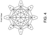
- FIG. 4 Another embodiment is shown in Fig. 4 , in which a series of transcievers (acoustic transmitters and receivers) are positioned around an exhaust plume. In this manner a three dimensional velocity contour of the exhaust plume may be determined from the respective velocities Vij across each path Sij, where i is the transmitter and j is the receiver.
- mass flow may be through a cylindrical passage having a diameter D and axis A oriented along the direction of mass flow.
- Transmitter T1 disposed across the mass flow from microphones M1 and M2, and these acoustic components may be disposed such that they are axially spaced by a distance of between 1 ⁇ 4 D and 2 D from the transmitter.
- transmitter T1 may be upstream of microphone M1 by a distance of between 1 ⁇ 4 D and 2 D.
- microphone M1 may be upstream of microphone M2 by a distance of between 1 ⁇ 4 D and 2 D.
- transmitter T1 may be upstream of microphone M2 by a distance of between 1 ⁇ 4 D and 2 D.
- the selection of distance may be a function of the homogeneity of the medium and space limitations. While greater distances may provide more accurate results, the homogeneity of the flow and the physical requirements (weight, drag, cost) of containing the flow over the distances weigh heavily against excessive spacing.
- the accurate determination of time delays between measured signals is a crucial performance requirement. Since signals in real environments are often polluted by acoustic noise, the accuracy of this determination can vary. In high noise applications, such as encountered for flows with Mach numbers approaching 1, determination of the true acoustic time delays will require a robust and proven signal processing technique.
- An embodiment of the present disclosure uses an amplitude modulated sinusoid output in a burst with duration of two modulation periods.
- s t sin 2 ⁇ f m t sin 2 ⁇ f c t , t ⁇ 2 / f c 0 , t > 2 / f c
- the modulation frequency, f m was chosen to be one tenth, f c , or 4 kHz modulation, resulting in an emitted burst duration of 0.5 milliseconds.
- the short burst allows for more distinct acoustic signatures to be transmitted during the measurement duration.
- the increase in number of acoustic events ultimately reduces the uncertainty of the mean time delay estimation.
- the signal time-of-flight exceeded a single 40 kHz wave period, negating the use of a continuous signal.
- the amplitude modulation helped to reduce this source of error associated with high frequency signals.
- time delay estimations exhibited 2 ⁇ ambiguities that appeared as errors in increments of 1/(40 kHz ) seconds (one carrier signal period).
- sound pulses or chirps may be used to assist in identifying the signal to the receiver.
- the receiver must match a received signal such as a sound pulse or chirp against the profile of a sound pulse or chirp the receiver expected to receive.
- a cross-correlation approach for acoustic event time determination was used to estimate time delays between the transmitter and microphone signals. Before performing this procedure on the signals, each measurement set was preconditioned to improve the accuracy of the estimator. This pre-conditioning was performed by setting to zero any signal regions known not to have originated from the sound source. A range of conceivable time delays were determined using maximum and minimum flow velocities and temperatures and used to isolate signal-containing portions of the time series. This technique minimized the influence of flow noise on the cross correlation algorithm.
- the full one second transmitter signal was cross-correlated with the entire one second microphone signal. After the time delay estimate was obtained, the process was repeated for the remaining 99 signal pairs. Using 100 time delay samples, the standard deviation of the samples was determined and specified for the set SNR value.
- the one second signal pairs were first divided into 30 different bins, each containing an acoustic burst measurement. Each transmitter bin was then cross correlated with its corresponding microphone bin to find 30 time delay estimates for the one second transmitter and microphone signal. The 30 time delays from binned signals were averaged, and one time delay estimate was found for a one second signal pair. The process was repeated for the remaining 99 signal pairs, and the standard deviation was determined for the set SNR value.
- an ultrasonic American Piezo 40 kHz transmitter may be used, which is capable of transmitting sound pressure levels up to 117 dB (measured 30 cm from source) with a driving voltage of 10 Vrms.
- the signal is much easier to detect due to the relatively reduced flow noise present at high frequencies.
- the signal may also be produced in other manners, such as a Hartmann generator utilizing bleed air, electrical arcs, or other known acoustic producing methods.
- the new form of sonic anemometry currently developed was applied for measurements near the nozzle exit of a high speed jet at varying set Mach numbers.
- the jet velocities were determined by evaluating equations (3) and (4) for the measured time delay values and the relative distances between the acoustic components.
- the Modified Sonic Anemometry (MSA) measurements were validated using the jet isentropic Mach number based upon the measured nozzle pressure ratio, and the facility total temperature was used to obtain sound speed and, thus, jet velocity.
- equation (5) the partial derivative terms were determined using equation (3), and the u terms represent the uncertainty in the subscripted term's measurement.
- f o is the carrier frequency
- ⁇ is the phase angle uncertainty.
- C 2 4 ⁇ f o L should scale the velocity uncertainty.
- the evaluation of this term for the carrier frequency (40 kHz), L and room temperature sound speed was 0.82 m/s.
- This relationship enables instrumentation scaling and parametric studies of performance parameters, such as changing f o . For instance, in the latter example, a doubling of f o is seen to halve the scaled velocity uncertainty. The same can be said for scaled increases of the propagation length L.
- the sound speed is proportional to T , the velocity uncertainty scales directly as the flow static temperature.
- Method 900 begins at block 901.
- At block 903 at least one acoustic transmitter T1 is positioned at or proximate the boundary of a flow passage containing a flowing medium.
- the flow medium may be air, or air mixed with exhaust gases, or exhaust gases with entrained particulate.
- the flowing medium may be flowing at greater than 0.3 Mach.
- the flowing medium may be the bypass fan exhaust of a turbine engine.
- At 905 at least two acoustic receivers are positioned at or proximate the boundary.
- a first acoustic receiver may be positioned downstream from the acoustic transmitter, and a second acoustic receiver may be positioned downstream from the first acoustic receiver.
- the acoustic receivers may be positioned across the flow passage from the acoustic transmitter.
- the acoustic transmitter transmits an acoustic signal across the flowing medium in the flow passage.
- the acoustic signal may be an amplitude modulated sinusoid and/or a chirp.
- the acoustic signal may have a frequency of 40 kHz or greater.
- the step of transmitting an acoustic signal at block 907 may further comprise bleeding air from a compressor for generation of the acoustic signal.
- the acoustic signal is received at the first acoustic receiver at block 909 and at the second acoustic receiver at block 911.
- a first transit time between the acoustic transmitter and the first acoustic receiver is determined, and a second transit time between the acoustic transmitter and the second acoustic receiver is determined.
- Based on the first and second transit times a velocity of the flowing medium is determined at block 915.
- the determining steps at 913 and 915 may be performed by a processor coupled to each of the acoustic transmitter and/or first and second acoustic receivers.
- the method 900 ends at block 917.
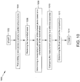
- the present disclosure additionally provides a method 1000 of non-intrusively determining thrust in real time in a gas turbine engine having an exhaust plume that is at least partially bounded.
- the method 1000 begins at block 1002.
- a wave is transmitted across the partially bounded exhaust plume.
- the wave is received at block 1006.
- the transmitted wave may be a sound or a light.
- the step of receiving the wave may comprise receiving the transmitted wave at a plurality of receivers, with the receivers axially displaced from each other.
- a measurement parameter of the exhaust plume is determined based on a characteristic of the received wave.
- the measurement parameter may be a function of the velocity of the exhaust plume, or may be a function of the velocity and temperature of the exhaust plume, or may be a function of the temperature of the exhaust plume.
- the characteristic of the received wave may be time of arrival, frequency, or refraction.
- the measurement parameter is compared to a reference parameter.
- the reference parameter may be a prior measurement parameter, and may be a predetermined parameter, and may be a function of inlet velocity and/or inlet temperature.
- the thrust is determined based on the comparison performed at block 1010.
- the method 1000 ends at block 1014.
Landscapes
- Physics & Mathematics (AREA)
- Engineering & Computer Science (AREA)
- General Physics & Mathematics (AREA)
- Combustion & Propulsion (AREA)
- Chemical & Material Sciences (AREA)
- Electromagnetism (AREA)
- Aviation & Aerospace Engineering (AREA)
- Multimedia (AREA)
- Acoustics & Sound (AREA)
- Fluid Mechanics (AREA)
- Ocean & Marine Engineering (AREA)
- Mechanical Engineering (AREA)
- General Engineering & Computer Science (AREA)
- Measurement Of Mechanical Vibrations Or Ultrasonic Waves (AREA)
- Measuring Temperature Or Quantity Of Heat (AREA)
- Investigating Or Analyzing Materials By The Use Of Ultrasonic Waves (AREA)
Applications Claiming Priority (2)
| Application Number | Priority Date | Filing Date | Title |
|---|---|---|---|
| US201662348684P | 2016-06-10 | 2016-06-10 | |
| US15/617,028 US10364698B2 (en) | 2016-06-10 | 2017-06-08 | System and method of non-intrusive thrust measurement |
Publications (3)
| Publication Number | Publication Date |
|---|---|
| EP3264104A2 true EP3264104A2 (fr) | 2018-01-03 |
| EP3264104A3 EP3264104A3 (fr) | 2018-03-14 |
| EP3264104B1 EP3264104B1 (fr) | 2020-12-30 |
Family
ID=59077833
Family Applications (1)
| Application Number | Title | Priority Date | Filing Date |
|---|---|---|---|
| EP17175331.2A Active EP3264104B1 (fr) | 2016-06-10 | 2017-06-09 | Procédé de mesure de poussée non intrusive |
Country Status (3)
| Country | Link |
|---|---|
| US (1) | US10364698B2 (fr) |
| EP (1) | EP3264104B1 (fr) |
| CA (1) | CA2970189C (fr) |
Cited By (5)
| Publication number | Priority date | Publication date | Assignee | Title |
|---|---|---|---|---|
| EP4112886A1 (fr) * | 2021-07-02 | 2023-01-04 | Raytheon Technologies Corporation | Débit massique et poussée de propulsion mesurés en vol sur les avions |
| US11747236B2 (en) | 2020-09-10 | 2023-09-05 | Virginia Tech Intellectual Properties, Inc. | Flow measurement for a gas turbine engine |
| US11796358B2 (en) | 2020-09-10 | 2023-10-24 | Virginia Tech Intellectual Properties, Inc. | Flow measurement for a gas turbine engine |
| US11815048B2 (en) | 2020-09-10 | 2023-11-14 | Rolls-Royce Plc | Gas turbine engine with airflow measurement system |
| US11821771B2 (en) | 2020-09-10 | 2023-11-21 | Virginia Tech Intellectual Properties, Inc. | Flow measurement for a gas turbine engine |
Families Citing this family (10)
| Publication number | Priority date | Publication date | Assignee | Title |
|---|---|---|---|---|
| US9927325B2 (en) * | 2014-03-13 | 2018-03-27 | Siemens Energy, Inc. | Method and system for determining distribution of temperature and velocity in a gas turbine engine |
| CN106640722B (zh) * | 2017-01-24 | 2019-03-01 | 中国科学院工程热物理研究所 | 一种压气机气动稳定性诊断和控制的装置及方法 |
| US10739371B2 (en) * | 2018-08-16 | 2020-08-11 | Rosemount Aerospace Inc. | Acoustic airspeed sensors |
| US10900990B2 (en) * | 2019-03-21 | 2021-01-26 | Rosemount Aerospace Inc. | Acoustic air data sensing systems with skin friction sensors |
| US11016114B1 (en) * | 2020-02-11 | 2021-05-25 | Rosemount Aerospace Inc. | Determining aircraft flying conditions based on acoustic signals caused by airflow |
| US12572781B2 (en) | 2020-08-21 | 2026-03-10 | Georgia Tech Research Corporation | Virtual-sensing integrated for predictive reliability |
| CN114013683B (zh) * | 2021-11-05 | 2023-11-28 | 中国航发沈阳发动机研究所 | 一种发动机风扇声衬降噪性能测试方法 |
| CN114235251B (zh) * | 2021-12-03 | 2024-05-28 | 北京东方计量测试研究所 | 真空下等离子推进器推力测量装置 |
| CN115077639B (zh) * | 2022-08-22 | 2023-01-13 | 水发航宇星物联科技(辽宁)有限公司 | 用于超声波流量计的测量方法 |
| CN116443270B (zh) * | 2023-06-02 | 2026-03-13 | 广东汇天航空航天科技有限公司 | 飞行器旋翼测试设备 |
Family Cites Families (10)
| Publication number | Priority date | Publication date | Assignee | Title |
|---|---|---|---|---|
| GB2132367B (en) | 1982-11-10 | 1986-01-15 | Rolls Royce | Thrust and airflow monitor for aeroengine test cells |
| US5178002A (en) | 1991-10-18 | 1993-01-12 | The Board Of Trustees Of The Leland Stanford Jr. University | Spectroscopy-based thrust sensor for high-speed gaseous flows |
| US5293775A (en) * | 1992-11-02 | 1994-03-15 | United Technologies Corporation | Gas turbine engine test cell |
| GB2384058B (en) * | 2002-01-15 | 2005-11-30 | Rolls Royce Plc | Thrust correction |
| GB2438431B (en) | 2006-05-25 | 2008-08-20 | Rolls Royce Plc | Thrust correction |
| DE102008041916B3 (de) * | 2008-09-09 | 2010-01-21 | Anecom Aerotest Gmbh | Testvorrichtung für den Fan eines Flugzeugtriebwerks |
| US7658114B1 (en) | 2008-11-17 | 2010-02-09 | General Electric Company | Ultrasonic flow meter |
| US8919207B2 (en) | 2012-01-10 | 2014-12-30 | General Electric Company | Flow measuring device and method using transmission paths having different angles |
| US20150098842A1 (en) | 2013-10-04 | 2015-04-09 | Harry Menian | Impulse Plus Propulsion System |
| US9927325B2 (en) | 2014-03-13 | 2018-03-27 | Siemens Energy, Inc. | Method and system for determining distribution of temperature and velocity in a gas turbine engine |
-
2017
- 2017-06-08 US US15/617,028 patent/US10364698B2/en active Active
- 2017-06-09 EP EP17175331.2A patent/EP3264104B1/fr active Active
- 2017-06-09 CA CA2970189A patent/CA2970189C/fr active Active
Non-Patent Citations (1)
| Title |
|---|
| None |
Cited By (5)
| Publication number | Priority date | Publication date | Assignee | Title |
|---|---|---|---|---|
| US11747236B2 (en) | 2020-09-10 | 2023-09-05 | Virginia Tech Intellectual Properties, Inc. | Flow measurement for a gas turbine engine |
| US11796358B2 (en) | 2020-09-10 | 2023-10-24 | Virginia Tech Intellectual Properties, Inc. | Flow measurement for a gas turbine engine |
| US11815048B2 (en) | 2020-09-10 | 2023-11-14 | Rolls-Royce Plc | Gas turbine engine with airflow measurement system |
| US11821771B2 (en) | 2020-09-10 | 2023-11-21 | Virginia Tech Intellectual Properties, Inc. | Flow measurement for a gas turbine engine |
| EP4112886A1 (fr) * | 2021-07-02 | 2023-01-04 | Raytheon Technologies Corporation | Débit massique et poussée de propulsion mesurés en vol sur les avions |
Also Published As
| Publication number | Publication date |
|---|---|
| US20170356303A1 (en) | 2017-12-14 |
| CA2970189C (fr) | 2023-08-01 |
| EP3264104B1 (fr) | 2020-12-30 |
| US10364698B2 (en) | 2019-07-30 |
| CA2970189A1 (fr) | 2017-12-10 |
| EP3264104A3 (fr) | 2018-03-14 |
Similar Documents
| Publication | Publication Date | Title |
|---|---|---|
| US10364698B2 (en) | System and method of non-intrusive thrust measurement | |
| US10281307B2 (en) | System and method of non-intrusive anemometry | |
| RU2159443C2 (ru) | Система аэронавигационных данных | |
| CA2513248C (fr) | Appareil et procede utilisant un reseau de capteurs ultrasoniques pour determiner la velocite d'un fluide dans un tuyau | |
| CN104777328B (zh) | 一种可听声测量气体流速的系统及测量方法 | |
| Otero et al. | Extension of sonic anemometry to high subsonic mach number flows | |
| Veltin et al. | Correlation of flowfield and acoustic field measurements in high-speed jets | |
| Li et al. | A novel differential time-of-flight algorithm for high-precision ultrasonic gas flow measurement | |
| Ozawa et al. | Comparison of time-averaged supersonic jet profile acquired by particle image velocimetry and shadowgraph velocimetry using single pixel ensemble correlation | |
| Pettinari et al. | Time-of-flight estimation in acoustic pyrometry: sensitivity to pulse characteristics | |
| Schulz et al. | Acoustic damping analysis of bias flow liners based on spectral flow characteristics | |
| Ortiz et al. | Correlation and spectral methods for determining uncertainty in propagating discontinuities | |
| Mansfeld et al. | A Pulse Correlated Gas Flowmeter with Clamp-On Sensors | |
| Hahn et al. | Investigation of flow induced sound radiated by a forward facing step | |
| Zhao et al. | A flue gas velocimeter based on the hyperbolic chirp modulation method of acoustic source signal | |
| White et al. | Leading-edge acoustic receptivity measurements using a pulsed-sound technique | |
| Feuillard et al. | Development of a flush ultrasonic probe for the measurement of the velocity and the angle of attack of an aircraft | |
| JPH0337523A (ja) | 流速計 | |
| RU2430381C2 (ru) | Способ определения скорости потока и расхода жидких и газообразных продуктов | |
| Gillespie et al. | Thrust Measurements using Acoustic Sensing on a Turbofan Engine Exhaust Plume | |
| Boucheron et al. | Evaluation of acoustic velocity in mean flow by Laser Doppler Velocimetry | |
| Veltin et al. | Correlation of flow and acoustic field measurements in high speed jets | |
| Murgan et al. | (A new time of flight) Acoustic flow meter using wide band signals and adaptive beamforming techniques | |
| Breakey | CHARACTERIZATION OF NOISE SOURCE MECHANISMS IN JETS | |
| Chou et al. | Turbulence measurements in a resonance tube |
Legal Events
| Date | Code | Title | Description |
|---|---|---|---|
| PUAI | Public reference made under article 153(3) epc to a published international application that has entered the european phase |
Free format text: ORIGINAL CODE: 0009012 |
|
| STAA | Information on the status of an ep patent application or granted ep patent |
Free format text: STATUS: THE APPLICATION HAS BEEN PUBLISHED |
|
| AK | Designated contracting states |
Kind code of ref document: A2 Designated state(s): AL AT BE BG CH CY CZ DE DK EE ES FI FR GB GR HR HU IE IS IT LI LT LU LV MC MK MT NL NO PL PT RO RS SE SI SK SM TR |
|
| AX | Request for extension of the european patent |
Extension state: BA ME |
|
| PUAL | Search report despatched |
Free format text: ORIGINAL CODE: 0009013 |
|
| AK | Designated contracting states |
Kind code of ref document: A3 Designated state(s): AL AT BE BG CH CY CZ DE DK EE ES FI FR GB GR HR HU IE IS IT LI LT LU LV MC MK MT NL NO PL PT RO RS SE SI SK SM TR |
|
| AX | Request for extension of the european patent |
Extension state: BA ME |
|
| RIC1 | Information provided on ipc code assigned before grant |
Ipc: G01L 5/13 20060101ALI20180202BHEP Ipc: G01P 5/24 20060101AFI20180202BHEP Ipc: G01F 1/66 20060101ALI20180202BHEP |
|
| STAA | Information on the status of an ep patent application or granted ep patent |
Free format text: STATUS: REQUEST FOR EXAMINATION WAS MADE |
|
| 17P | Request for examination filed |
Effective date: 20180913 |
|
| RBV | Designated contracting states (corrected) |
Designated state(s): AL AT BE BG CH CY CZ DE DK EE ES FI FR GB GR HR HU IE IS IT LI LT LU LV MC MK MT NL NO PL PT RO RS SE SI SK SM TR |
|
| STAA | Information on the status of an ep patent application or granted ep patent |
Free format text: STATUS: EXAMINATION IS IN PROGRESS |
|
| 17Q | First examination report despatched |
Effective date: 20190503 |
|
| RIC1 | Information provided on ipc code assigned before grant |
Ipc: G01P 5/24 20060101AFI20200805BHEP Ipc: G01M 15/14 20060101ALI20200805BHEP Ipc: G01F 1/66 20060101ALI20200805BHEP Ipc: G01L 5/13 20060101ALI20200805BHEP |
|
| GRAP | Despatch of communication of intention to grant a patent |
Free format text: ORIGINAL CODE: EPIDOSNIGR1 |
|
| STAA | Information on the status of an ep patent application or granted ep patent |
Free format text: STATUS: GRANT OF PATENT IS INTENDED |
|
| INTG | Intention to grant announced |
Effective date: 20200915 |
|
| GRAS | Grant fee paid |
Free format text: ORIGINAL CODE: EPIDOSNIGR3 |
|
| GRAA | (expected) grant |
Free format text: ORIGINAL CODE: 0009210 |
|
| STAA | Information on the status of an ep patent application or granted ep patent |
Free format text: STATUS: THE PATENT HAS BEEN GRANTED |
|
| AK | Designated contracting states |
Kind code of ref document: B1 Designated state(s): AL AT BE BG CH CY CZ DE DK EE ES FI FR GB GR HR HU IE IS IT LI LT LU LV MC MK MT NL NO PL PT RO RS SE SI SK SM TR |
|
| REG | Reference to a national code |
Ref country code: GB Ref legal event code: FG4D |
|
| REG | Reference to a national code |
Ref country code: AT Ref legal event code: REF Ref document number: 1350451 Country of ref document: AT Kind code of ref document: T Effective date: 20210115 |
|
| REG | Reference to a national code |
Ref country code: DE Ref legal event code: R096 Ref document number: 602017030322 Country of ref document: DE |
|
| REG | Reference to a national code |
Ref country code: IE Ref legal event code: FG4D |
|
| PG25 | Lapsed in a contracting state [announced via postgrant information from national office to epo] |
Ref country code: FI Free format text: LAPSE BECAUSE OF FAILURE TO SUBMIT A TRANSLATION OF THE DESCRIPTION OR TO PAY THE FEE WITHIN THE PRESCRIBED TIME-LIMIT Effective date: 20201230 Ref country code: GR Free format text: LAPSE BECAUSE OF FAILURE TO SUBMIT A TRANSLATION OF THE DESCRIPTION OR TO PAY THE FEE WITHIN THE PRESCRIBED TIME-LIMIT Effective date: 20210331 Ref country code: RS Free format text: LAPSE BECAUSE OF FAILURE TO SUBMIT A TRANSLATION OF THE DESCRIPTION OR TO PAY THE FEE WITHIN THE PRESCRIBED TIME-LIMIT Effective date: 20201230 Ref country code: NO Free format text: LAPSE BECAUSE OF FAILURE TO SUBMIT A TRANSLATION OF THE DESCRIPTION OR TO PAY THE FEE WITHIN THE PRESCRIBED TIME-LIMIT Effective date: 20210330 |
|
| REG | Reference to a national code |
Ref country code: AT Ref legal event code: MK05 Ref document number: 1350451 Country of ref document: AT Kind code of ref document: T Effective date: 20201230 |
|
| PG25 | Lapsed in a contracting state [announced via postgrant information from national office to epo] |
Ref country code: SE Free format text: LAPSE BECAUSE OF FAILURE TO SUBMIT A TRANSLATION OF THE DESCRIPTION OR TO PAY THE FEE WITHIN THE PRESCRIBED TIME-LIMIT Effective date: 20201230 Ref country code: BG Free format text: LAPSE BECAUSE OF FAILURE TO SUBMIT A TRANSLATION OF THE DESCRIPTION OR TO PAY THE FEE WITHIN THE PRESCRIBED TIME-LIMIT Effective date: 20210330 Ref country code: LV Free format text: LAPSE BECAUSE OF FAILURE TO SUBMIT A TRANSLATION OF THE DESCRIPTION OR TO PAY THE FEE WITHIN THE PRESCRIBED TIME-LIMIT Effective date: 20201230 |
|
| REG | Reference to a national code |
Ref country code: NL Ref legal event code: MP Effective date: 20201230 |
|
| PG25 | Lapsed in a contracting state [announced via postgrant information from national office to epo] |
Ref country code: HR Free format text: LAPSE BECAUSE OF FAILURE TO SUBMIT A TRANSLATION OF THE DESCRIPTION OR TO PAY THE FEE WITHIN THE PRESCRIBED TIME-LIMIT Effective date: 20201230 |
|
| REG | Reference to a national code |
Ref country code: LT Ref legal event code: MG9D |
|
| PG25 | Lapsed in a contracting state [announced via postgrant information from national office to epo] |
Ref country code: LT Free format text: LAPSE BECAUSE OF FAILURE TO SUBMIT A TRANSLATION OF THE DESCRIPTION OR TO PAY THE FEE WITHIN THE PRESCRIBED TIME-LIMIT Effective date: 20201230 Ref country code: CZ Free format text: LAPSE BECAUSE OF FAILURE TO SUBMIT A TRANSLATION OF THE DESCRIPTION OR TO PAY THE FEE WITHIN THE PRESCRIBED TIME-LIMIT Effective date: 20201230 Ref country code: EE Free format text: LAPSE BECAUSE OF FAILURE TO SUBMIT A TRANSLATION OF THE DESCRIPTION OR TO PAY THE FEE WITHIN THE PRESCRIBED TIME-LIMIT Effective date: 20201230 Ref country code: PT Free format text: LAPSE BECAUSE OF FAILURE TO SUBMIT A TRANSLATION OF THE DESCRIPTION OR TO PAY THE FEE WITHIN THE PRESCRIBED TIME-LIMIT Effective date: 20210430 Ref country code: SK Free format text: LAPSE BECAUSE OF FAILURE TO SUBMIT A TRANSLATION OF THE DESCRIPTION OR TO PAY THE FEE WITHIN THE PRESCRIBED TIME-LIMIT Effective date: 20201230 Ref country code: RO Free format text: LAPSE BECAUSE OF FAILURE TO SUBMIT A TRANSLATION OF THE DESCRIPTION OR TO PAY THE FEE WITHIN THE PRESCRIBED TIME-LIMIT Effective date: 20201230 |
|
| PG25 | Lapsed in a contracting state [announced via postgrant information from national office to epo] |
Ref country code: AT Free format text: LAPSE BECAUSE OF FAILURE TO SUBMIT A TRANSLATION OF THE DESCRIPTION OR TO PAY THE FEE WITHIN THE PRESCRIBED TIME-LIMIT Effective date: 20201230 Ref country code: PL Free format text: LAPSE BECAUSE OF FAILURE TO SUBMIT A TRANSLATION OF THE DESCRIPTION OR TO PAY THE FEE WITHIN THE PRESCRIBED TIME-LIMIT Effective date: 20201230 |
|
| PG25 | Lapsed in a contracting state [announced via postgrant information from national office to epo] |
Ref country code: IS Free format text: LAPSE BECAUSE OF FAILURE TO SUBMIT A TRANSLATION OF THE DESCRIPTION OR TO PAY THE FEE WITHIN THE PRESCRIBED TIME-LIMIT Effective date: 20210430 |
|
| REG | Reference to a national code |
Ref country code: DE Ref legal event code: R097 Ref document number: 602017030322 Country of ref document: DE |
|
| PG25 | Lapsed in a contracting state [announced via postgrant information from national office to epo] |
Ref country code: AL Free format text: LAPSE BECAUSE OF FAILURE TO SUBMIT A TRANSLATION OF THE DESCRIPTION OR TO PAY THE FEE WITHIN THE PRESCRIBED TIME-LIMIT Effective date: 20201230 Ref country code: IT Free format text: LAPSE BECAUSE OF FAILURE TO SUBMIT A TRANSLATION OF THE DESCRIPTION OR TO PAY THE FEE WITHIN THE PRESCRIBED TIME-LIMIT Effective date: 20201230 |
|
| PLBE | No opposition filed within time limit |
Free format text: ORIGINAL CODE: 0009261 |
|
| STAA | Information on the status of an ep patent application or granted ep patent |
Free format text: STATUS: NO OPPOSITION FILED WITHIN TIME LIMIT |
|
| PG25 | Lapsed in a contracting state [announced via postgrant information from national office to epo] |
Ref country code: DK Free format text: LAPSE BECAUSE OF FAILURE TO SUBMIT A TRANSLATION OF THE DESCRIPTION OR TO PAY THE FEE WITHIN THE PRESCRIBED TIME-LIMIT Effective date: 20201230 |
|
| 26N | No opposition filed |
Effective date: 20211001 |
|
| REG | Reference to a national code |
Ref country code: DE Ref legal event code: R119 Ref document number: 602017030322 Country of ref document: DE |
|
| PG25 | Lapsed in a contracting state [announced via postgrant information from national office to epo] |
Ref country code: ES Free format text: LAPSE BECAUSE OF FAILURE TO SUBMIT A TRANSLATION OF THE DESCRIPTION OR TO PAY THE FEE WITHIN THE PRESCRIBED TIME-LIMIT Effective date: 20201230 Ref country code: MC Free format text: LAPSE BECAUSE OF FAILURE TO SUBMIT A TRANSLATION OF THE DESCRIPTION OR TO PAY THE FEE WITHIN THE PRESCRIBED TIME-LIMIT Effective date: 20201230 |
|
| REG | Reference to a national code |
Ref country code: CH Ref legal event code: PL |
|
| GBPC | Gb: european patent ceased through non-payment of renewal fee |
Effective date: 20210609 |
|
| PG25 | Lapsed in a contracting state [announced via postgrant information from national office to epo] |
Ref country code: SI Free format text: LAPSE BECAUSE OF FAILURE TO SUBMIT A TRANSLATION OF THE DESCRIPTION OR TO PAY THE FEE WITHIN THE PRESCRIBED TIME-LIMIT Effective date: 20201230 |
|
| REG | Reference to a national code |
Ref country code: BE Ref legal event code: MM Effective date: 20210630 |
|
| PG25 | Lapsed in a contracting state [announced via postgrant information from national office to epo] |
Ref country code: LU Free format text: LAPSE BECAUSE OF NON-PAYMENT OF DUE FEES Effective date: 20210609 |
|
| PG25 | Lapsed in a contracting state [announced via postgrant information from national office to epo] |
Ref country code: LI Free format text: LAPSE BECAUSE OF NON-PAYMENT OF DUE FEES Effective date: 20210630 Ref country code: IE Free format text: LAPSE BECAUSE OF NON-PAYMENT OF DUE FEES Effective date: 20210609 Ref country code: DE Free format text: LAPSE BECAUSE OF NON-PAYMENT OF DUE FEES Effective date: 20220101 Ref country code: CH Free format text: LAPSE BECAUSE OF NON-PAYMENT OF DUE FEES Effective date: 20210630 Ref country code: GB Free format text: LAPSE BECAUSE OF NON-PAYMENT OF DUE FEES Effective date: 20210609 |
|
| PG25 | Lapsed in a contracting state [announced via postgrant information from national office to epo] |
Ref country code: IS Free format text: LAPSE BECAUSE OF FAILURE TO SUBMIT A TRANSLATION OF THE DESCRIPTION OR TO PAY THE FEE WITHIN THE PRESCRIBED TIME-LIMIT Effective date: 20210430 |
|
| PG25 | Lapsed in a contracting state [announced via postgrant information from national office to epo] |
Ref country code: BE Free format text: LAPSE BECAUSE OF NON-PAYMENT OF DUE FEES Effective date: 20210630 |
|
| PG25 | Lapsed in a contracting state [announced via postgrant information from national office to epo] |
Ref country code: HU Free format text: LAPSE BECAUSE OF FAILURE TO SUBMIT A TRANSLATION OF THE DESCRIPTION OR TO PAY THE FEE WITHIN THE PRESCRIBED TIME-LIMIT; INVALID AB INITIO Effective date: 20170609 |
|
| PG25 | Lapsed in a contracting state [announced via postgrant information from national office to epo] |
Ref country code: NL Free format text: LAPSE BECAUSE OF NON-PAYMENT OF DUE FEES Effective date: 20201230 Ref country code: CY Free format text: LAPSE BECAUSE OF FAILURE TO SUBMIT A TRANSLATION OF THE DESCRIPTION OR TO PAY THE FEE WITHIN THE PRESCRIBED TIME-LIMIT Effective date: 20201230 |
|
| P01 | Opt-out of the competence of the unified patent court (upc) registered |
Effective date: 20230528 |
|
| PG25 | Lapsed in a contracting state [announced via postgrant information from national office to epo] |
Ref country code: SM Free format text: LAPSE BECAUSE OF FAILURE TO SUBMIT A TRANSLATION OF THE DESCRIPTION OR TO PAY THE FEE WITHIN THE PRESCRIBED TIME-LIMIT Effective date: 20201230 |
|
| PG25 | Lapsed in a contracting state [announced via postgrant information from national office to epo] |
Ref country code: MK Free format text: LAPSE BECAUSE OF FAILURE TO SUBMIT A TRANSLATION OF THE DESCRIPTION OR TO PAY THE FEE WITHIN THE PRESCRIBED TIME-LIMIT Effective date: 20201230 |
|
| PG25 | Lapsed in a contracting state [announced via postgrant information from national office to epo] |
Ref country code: TR Free format text: LAPSE BECAUSE OF FAILURE TO SUBMIT A TRANSLATION OF THE DESCRIPTION OR TO PAY THE FEE WITHIN THE PRESCRIBED TIME-LIMIT Effective date: 20201230 |
|
| PG25 | Lapsed in a contracting state [announced via postgrant information from national office to epo] |
Ref country code: MT Free format text: LAPSE BECAUSE OF FAILURE TO SUBMIT A TRANSLATION OF THE DESCRIPTION OR TO PAY THE FEE WITHIN THE PRESCRIBED TIME-LIMIT Effective date: 20201230 |
|
| PGFP | Annual fee paid to national office [announced via postgrant information from national office to epo] |
Ref country code: FR Payment date: 20250624 Year of fee payment: 9 |