EP3263929A1 - Sliding bearing - Google Patents
Sliding bearing Download PDFInfo
- Publication number
- EP3263929A1 EP3263929A1 EP16755739.6A EP16755739A EP3263929A1 EP 3263929 A1 EP3263929 A1 EP 3263929A1 EP 16755739 A EP16755739 A EP 16755739A EP 3263929 A1 EP3263929 A1 EP 3263929A1
- Authority
- EP
- European Patent Office
- Prior art keywords
- inner peripheral
- sliding bearing
- inclined part
- downstream side
- coating layer
- Prior art date
- Legal status (The legal status is an assumption and is not a legal conclusion. Google has not performed a legal analysis and makes no representation as to the accuracy of the status listed.)
- Withdrawn
Links
Images


Classifications
-
- F—MECHANICAL ENGINEERING; LIGHTING; HEATING; WEAPONS; BLASTING
- F16—ENGINEERING ELEMENTS AND UNITS; GENERAL MEASURES FOR PRODUCING AND MAINTAINING EFFECTIVE FUNCTIONING OF MACHINES OR INSTALLATIONS; THERMAL INSULATION IN GENERAL
- F16C—SHAFTS; FLEXIBLE SHAFTS; ELEMENTS OR CRANKSHAFT MECHANISMS; ROTARY BODIES OTHER THAN GEARING ELEMENTS; BEARINGS
- F16C33/00—Parts of bearings; Special methods for making bearings or parts thereof
- F16C33/02—Parts of sliding-contact bearings
- F16C33/04—Brasses; Bushes; Linings
- F16C33/06—Sliding surface mainly made of metal
- F16C33/08—Attachment of brasses, bushes or linings to the bearing housing
-
- F—MECHANICAL ENGINEERING; LIGHTING; HEATING; WEAPONS; BLASTING
- F16—ENGINEERING ELEMENTS AND UNITS; GENERAL MEASURES FOR PRODUCING AND MAINTAINING EFFECTIVE FUNCTIONING OF MACHINES OR INSTALLATIONS; THERMAL INSULATION IN GENERAL
- F16C—SHAFTS; FLEXIBLE SHAFTS; ELEMENTS OR CRANKSHAFT MECHANISMS; ROTARY BODIES OTHER THAN GEARING ELEMENTS; BEARINGS
- F16C33/00—Parts of bearings; Special methods for making bearings or parts thereof
- F16C33/02—Parts of sliding-contact bearings
- F16C33/04—Brasses; Bushes; Linings
- F16C33/06—Sliding surface mainly made of metal
- F16C33/10—Construction relative to lubrication
- F16C33/1025—Construction relative to lubrication with liquid, e.g. oil, as lubricant
- F16C33/106—Details of distribution or circulation inside the bearings, e.g. details of the bearing surfaces to affect flow or pressure of the liquid
- F16C33/1065—Grooves on a bearing surface for distributing or collecting the liquid
-
- F—MECHANICAL ENGINEERING; LIGHTING; HEATING; WEAPONS; BLASTING
- F16—ENGINEERING ELEMENTS AND UNITS; GENERAL MEASURES FOR PRODUCING AND MAINTAINING EFFECTIVE FUNCTIONING OF MACHINES OR INSTALLATIONS; THERMAL INSULATION IN GENERAL
- F16C—SHAFTS; FLEXIBLE SHAFTS; ELEMENTS OR CRANKSHAFT MECHANISMS; ROTARY BODIES OTHER THAN GEARING ELEMENTS; BEARINGS
- F16C17/00—Sliding-contact bearings for exclusively rotary movement
- F16C17/02—Sliding-contact bearings for exclusively rotary movement for radial load only
-
- F—MECHANICAL ENGINEERING; LIGHTING; HEATING; WEAPONS; BLASTING
- F16—ENGINEERING ELEMENTS AND UNITS; GENERAL MEASURES FOR PRODUCING AND MAINTAINING EFFECTIVE FUNCTIONING OF MACHINES OR INSTALLATIONS; THERMAL INSULATION IN GENERAL
- F16C—SHAFTS; FLEXIBLE SHAFTS; ELEMENTS OR CRANKSHAFT MECHANISMS; ROTARY BODIES OTHER THAN GEARING ELEMENTS; BEARINGS
- F16C17/00—Sliding-contact bearings for exclusively rotary movement
- F16C17/02—Sliding-contact bearings for exclusively rotary movement for radial load only
- F16C17/022—Sliding-contact bearings for exclusively rotary movement for radial load only with a pair of essentially semicircular bearing sleeves
-
- F—MECHANICAL ENGINEERING; LIGHTING; HEATING; WEAPONS; BLASTING
- F16—ENGINEERING ELEMENTS AND UNITS; GENERAL MEASURES FOR PRODUCING AND MAINTAINING EFFECTIVE FUNCTIONING OF MACHINES OR INSTALLATIONS; THERMAL INSULATION IN GENERAL
- F16C—SHAFTS; FLEXIBLE SHAFTS; ELEMENTS OR CRANKSHAFT MECHANISMS; ROTARY BODIES OTHER THAN GEARING ELEMENTS; BEARINGS
- F16C33/00—Parts of bearings; Special methods for making bearings or parts thereof
- F16C33/02—Parts of sliding-contact bearings
- F16C33/04—Brasses; Bushes; Linings
- F16C33/046—Brasses; Bushes; Linings divided or split, e.g. half-bearings or rolled sleeves
-
- F—MECHANICAL ENGINEERING; LIGHTING; HEATING; WEAPONS; BLASTING
- F16—ENGINEERING ELEMENTS AND UNITS; GENERAL MEASURES FOR PRODUCING AND MAINTAINING EFFECTIVE FUNCTIONING OF MACHINES OR INSTALLATIONS; THERMAL INSULATION IN GENERAL
- F16C—SHAFTS; FLEXIBLE SHAFTS; ELEMENTS OR CRANKSHAFT MECHANISMS; ROTARY BODIES OTHER THAN GEARING ELEMENTS; BEARINGS
- F16C33/00—Parts of bearings; Special methods for making bearings or parts thereof
- F16C33/02—Parts of sliding-contact bearings
- F16C33/04—Brasses; Bushes; Linings
- F16C33/06—Sliding surface mainly made of metal
- F16C33/10—Construction relative to lubrication
-
- F—MECHANICAL ENGINEERING; LIGHTING; HEATING; WEAPONS; BLASTING
- F16—ENGINEERING ELEMENTS AND UNITS; GENERAL MEASURES FOR PRODUCING AND MAINTAINING EFFECTIVE FUNCTIONING OF MACHINES OR INSTALLATIONS; THERMAL INSULATION IN GENERAL
- F16C—SHAFTS; FLEXIBLE SHAFTS; ELEMENTS OR CRANKSHAFT MECHANISMS; ROTARY BODIES OTHER THAN GEARING ELEMENTS; BEARINGS
- F16C9/00—Bearings for crankshafts or connecting-rods; Attachment of connecting-rods
- F16C9/02—Crankshaft bearings
Definitions
- the present invention relates to a technique of a sliding bearing, and to a technique of a sliding bearing including vertically-arranged half members obtained by halving a cylinder in parallel with an axial direction of the cylinder.
- Such a bearing in which the narrow grooves are formed fails to achieve both a larger quantity of lead-in oil and a smaller quantity of outflow oil flowing through both axial direction ends. Thus, a further friction reducing effect has been unable to be expected.
- the present invention is made in view of the problem described above, and provides a sliding bearing with which it is possible to suppress the total quantity of outflow oil and to obtain a further friction reducing effect.
- the present invention is a sliding bearing including vertically-arranged half members obtained by halving a cylinder in parallel with an axial direction of the cylinder.
- a narrow groove is provided circumferentially to an axial direction end of the lower half member at a downstream side of a rotational direction.
- An inclined part that is inclined toward an inner peripheral side when approaching the downstream side is provided to a downstream side end, in the rotational direction, of the narrow groove.
- a coating layer is provided to at least part of an inner peripheral surface of the inclined part.
- an inclined part that is inclined toward an inner peripheral side when approaching an upstream side may be provided to an upstream side end, in the rotational direction, of the narrow groove.
- a coating layer may be provided to at least part of an inner peripheral surface of the inclined part.
- the coating layer may include at least one of molybdenum disulfide, graphite, carbon, polytetrafluoroethylene, boron nitride, tungsten disulfide, and fluorine-based resin.
- the present invention provides the following advantageous effects.
- the narrow groove is provided without hindering generation of oil film pressure, whereby a friction reducing effect can be obtained with a smaller sliding area and the total quantity of outflow oil can be reduced.
- the inclined parts are provided to the downstream side end and the upstream side end, in the rotational direction, of the narrow groove, and the coating layer is provided to the inner peripheral surface of the inclined parts.
- Fig. 1 is a front view of a sliding bearing 1, with a vertical direction of the sheet defined as an upper and lower direction, and a direction between a closer side and a farther side of the sheet defined as an axial direction (front and rear direction).
- the sliding bearing 1 is a cylindrical member, and is applied to a sliding bearing structure of a crankshaft 11 of an engine as illustrated in Fig. 1 .
- the sliding bearing 1 includes two half members 2 and 2.
- the two half members 2 and 2 have shapes formed by halving a cylinder in parallel with the axial direction of the cylinder, and each have a semicircular cross-sectional shape.
- the half members 2 and 2 are arranged in the upper and lower direction with joining surfaces provided on left and right sides.
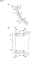
- Fig. 2(A) illustrates the half members 2 on upper and lower sides.
- a rotational direction of the crankshaft 11 corresponds to the clockwise direction in front view as indicated by an arrow in Fig. 1 .
- a bearing angle ⁇ is 0° at a right end position in Fig. 2(B) , and increases along the counterclockwise direction in Fig. 2(B) . More specifically, the bearing angle ⁇ in Fig. 2(B) is defined as 180° at a left end position, and as 270° at a lower end position.
- the half member 2 on the upper side has an inner circumference provided circumferentially with a groove that has a round hole at the center, and has the joining surfaces on the left and the right sides.
- the lower half member 2 has an inner circumference with axial direction ends provided with narrow grooves 3.
- a coating layer 23 is provided to an inner peripheral surface of the lower half member 2 as illustrated in Fig. 2(C) .
- the coating layer 23 includes at least one of molybdenum disulfide, graphite, carbon, polytetrafluoroethylene, boron nitride, tungsten disulfide, and fluorine-based resin.
- a peripheral section 2a is formed on a surface on the outer side of each of the narrow grooves 3 in the axial direction, and is formed to have a height h from an outer peripheral surface of the half member 2 that is shorter than a height D of a contact surface from the outer peripheral surface of the half member 2.
- the peripheral section 2a formed outward in the axial direction is formed to be one step lower than the contact surface, adjacent to the peripheral section 2a, to be in contact with the crankshaft 11.
- the narrow grooves 3 are described with reference to Fig. 2(B) and Fig. 2(C) .
- the narrow grooves 3 are provided on the lower half member 2.
- two narrow grooves 3 are arranged in parallel in the axial direction. More specifically, the narrow grooves 3 extend circumferentially to a bearing angle ⁇ 2 in a direction in which the bearing angle ⁇ increases (counterclockwise direction) from a position (with the bearing angle ⁇ of ( ⁇ 1) separated from the joining surface (with the bearing angle ⁇ of 180°) at a downstream side of a rotational direction of the crankshaft 11.
- the lower half member 2 has a joining surface on the right side in Fig. 2(B) as a joining surface at an upstream side of the rotational direction, and a joining surface on the left side in Fig. 2(B) as the joining surface at the downstream side of the rotational direction.
- the narrow grooves 3 are formed to have a width w as illustrated in Fig. 2(C) .
- the narrow grooves 3 are also formed to have a depth d shorter than the height D of the contact surface from the outer peripheral surface of the half member 2.
- the depth d to a bottom surface 3a of the narrow groove 3 changes from one end of the narrow groove 3 in the longitudinal direction toward the other end as illustrated in Fig. 3(A) .
- an inclined part 3b is provided to a downstream side end, in the rotational direction, of each of the narrow grooves 3.
- the inclined part 3b is inclined toward an inner peripheral side when approaching the downstream side, and has a curved shape that is more sharply inclined at a portion more on the downstream side as viewed in a cross-sectional view (cross-sectional view taken along the line II(B)-II(B)) in parallel with the longitudinal direction.
- An inclined part 3c is provided to an upstream side end, in the rotational direction, of each of the narrow grooves 3.
- the inclined part 3c is inclined toward an inner peripheral side when approaching the downstream side, and has a curved shape that is more sharply inclined at a portion more on the upstream side as viewed in the cross-sectional view (cross-sectional view taken along the line II(B)-II(B)) in parallel with the longitudinal direction.
- coating layers 23a and 23a are provided to at least part of inner peripheral surfaces of the inclined part 3b and the inclined part 3c.
- the coating layer 23 includes molybdenum disulfide, graphite, carbon, polytetrafluoroethylene, boron nitride, tungsten disulfide, or fluorine-based resin.
- the coating layer 23 with this configuration has lipophilicity.
- peripheral section 2a formed to be one step lower than the contact surface, adjacent to the peripheral section 2a, to be in contact with the crankshaft 11, the peripheral section 2a is less likely to be in contact with the crankshaft 11 inclined to be in a state of being in contact with one axial direction end (partial contact state), and thus can be prevented from being damaged.
- the peripheral section 2a is formed to be one step below the contact surface adjacent to the peripheral section 2a. Thus, a larger gap is achieved in the end portion of the sliding bearing 1 in the axial direction. Thus, the quantity of lead-in oil is increased and the total quantity of outflow oil is reduced.
- Coating layers 23b and 23b are provided on the upstream side end and the downstream side end of the peripheral section 2a in the inner peripheral surface.
- the coating layers 23b and 23b, provided on the inner peripheral surfaces of the peripheral section 2a, have low hardness. Thus, the foreign objects such as dust can be buried and captured in the coating layers 23b and 23b. With this configuration, the surface of the crankshaft 11 and the inner peripheral surface of the sliding bearing 1 can be prevented from being damaged by the foreign objects.
- a smaller FMEP is achieved.
- An especially smaller FMEP is achieved in a region with a low engine speed.
- the FMEP is a value indicating friction characteristics. Smaller FMEP leads to a lower friction. For example, at the timing of engine cold start, FMEP is reduced and the friction is reduced.
- the coating layers 23 are formed by being applied on the inner peripheral surfaces of the half members 2.
- the coating layer 23 is formed to cover the inner side end in the axial direction as illustrated in Fig. 3(A) . More specifically, the coating layer 23 is applied in an area between an end and an intermediate portion of a side surface of the narrow groove 3 on the inner side in the axial direction.
- This configuration where the coating layer 23 covers the inner side end of the narrow groove 3 in the axial direction can achieve a smaller friction between the inner side end of the narrow groove 3 in the axial direction and the crank shaft 11 when the crankshaft 11 is inclined to be in a state of being in contact with one end in the axial direction (partial contact state).
- the coating layer 23 may be formed to entirely cover the narrow groove 3 as illustrated in Fig. 4 . This configuration can achieve a smaller friction between the inner side end of the narrow groove 3 in the axial direction and the crank shaft 11 when the crankshaft 11 is inclined to be in a state of being in contact with one end in the axial direction (partial contact state).
- the sliding bearing 1 includes vertically-arranged half members 2 and 2 obtained by halving a cylinder in parallel with the axial direction of the cylinder.
- the narrow groove 3 is provided circumferentially to the axial direction end of the lower half member 2 at the downstream side of the rotational direction.
- the inclined part 3b which is inclined toward the inner peripheral side when approaching the downstream side, is provided to the downstream side end, in the rotational direction, of the narrow groove 3.
- the coating layer 23a is provided to at least part of the inner peripheral surface of the inclined part 3b.
- the narrow groove 3 is provided without hindering generation of oil film pressure, whereby a friction reducing effect can be obtained with a smaller sliding area and the total quantity of outflow oil can be reduced.
- the inclined part 3b is provided to the downstream side end, in the rotational direction, of the narrow groove 3, and the coating layer 23a is provided to the inner peripheral surface of the inclined part 3b.
- the foreign objects accumulated on the downstream side end of the narrow groove 3 in the rotational direction are captured by coating layer 23a.
- the surface of the crank shaft 11 and the inner peripheral surface of the sliding bearing 1 can be prevented from being damaged by the foreign objects.
- the inclined part 3c which is inclined toward the inner peripheral side when approaching an upstream side, is provided to the upstream side end, in the rotational direction, of the narrow groove 3.
- the coating layer 23a is provided to at least part of the inner peripheral surface of the inclined part 3c.
- the coating layer 23 includes at least one of molybdenum disulfide, graphite, carbon, polytetrafluoroethylene, boron nitride, tungsten disulfide, and fluorine-based resin.
- the coating layer 23a provided to the inclined part 3b of the downstream side end and the inclined part 3c of the upstream side end in the narrow groove 3 includes at least one of molybdenum disulfide, graphite, carbon, polytetrafluoroethylene, boron nitride, tungsten disulfide, and fluorine-based resin.
- the present invention can be applied to a technique for a sliding bearing, and can be applied to a technique for a sliding bearing including vertically-arranged half members obtained by halving a cylinder in parallel with an axial direction of the cylinder.
Landscapes
- Engineering & Computer Science (AREA)
- General Engineering & Computer Science (AREA)
- Mechanical Engineering (AREA)
- Chemical & Material Sciences (AREA)
- Oil, Petroleum & Natural Gas (AREA)
- Sliding-Contact Bearings (AREA)
- Shafts, Cranks, Connecting Bars, And Related Bearings (AREA)
Abstract
Description
- The present invention relates to a technique of a sliding bearing, and to a technique of a sliding bearing including vertically-arranged half members obtained by halving a cylinder in parallel with an axial direction of the cylinder.
- Conventionally known sliding bearings, for supporting a crankshaft of an engine, having a split structure in which two members obtained by halving a cylindrical member are combined are plagued by a large friction due to high viscosity of oil during a cold engine operation. Thus, one known bearing has relief portions (narrow grooves) formed over the entire circumference in both axial direction ends of the bearing (for example, see Patent Literature 1).
- PTL 1: Japanese Translation of
PCT International Application Publication No. JP-T-2003-532036 - Such a bearing in which the narrow grooves are formed fails to achieve both a larger quantity of lead-in oil and a smaller quantity of outflow oil flowing through both axial direction ends. Thus, a further friction reducing effect has been unable to be expected.
- Thus, the present invention is made in view of the problem described above, and provides a sliding bearing with which it is possible to suppress the total quantity of outflow oil and to obtain a further friction reducing effect.
- The problem of the present invention is as described above. Next, a solution to the problem is described.
- The present invention is a sliding bearing including vertically-arranged half members obtained by halving a cylinder in parallel with an axial direction of the cylinder. A narrow groove is provided circumferentially to an axial direction end of the lower half member at a downstream side of a rotational direction.
- An inclined part that is inclined toward an inner peripheral side when approaching the downstream side is provided to a downstream side end, in the rotational direction, of the narrow groove. A coating layer is provided to at least part of an inner peripheral surface of the inclined part.
- In the present invention, an inclined part that is inclined toward an inner peripheral side when approaching an upstream side may be provided to an upstream side end, in the rotational direction, of the narrow groove. A coating layer may be provided to at least part of an inner peripheral surface of the inclined part.
- In the present invention, the coating layer may include at least one of molybdenum disulfide, graphite, carbon, polytetrafluoroethylene, boron nitride, tungsten disulfide, and fluorine-based resin.
- The present invention provides the following advantageous effects.
- The narrow groove is provided without hindering generation of oil film pressure, whereby a friction reducing effect can be obtained with a smaller sliding area and the total quantity of outflow oil can be reduced. The inclined parts are provided to the downstream side end and the upstream side end, in the rotational direction, of the narrow groove, and the coating layer is provided to the inner peripheral surface of the inclined parts. Thus, foreign objects accumulated in a downstream side end and an upstream side end of the narrow groove in a rotational direction can be captured by the coating layer, whereby a surface of a shaft and an inner peripheral surface of the sliding bearing can be prevented from being damaged (seized or scratched) by the foreign objects.
-
- [
Fig. 1] Fig. 1 is a front view of a sliding bearing according to an embodiment of the present invention. - [
Fig. 2] Fig. 2(A) is a plan view of a half member as part of the sliding bearing according to the embodiment of the present invention,Fig. 2(B) is a cross-sectional view of the same taken along line II(B)-II(B), andFig. 2(C) is a cross-sectional view of the same taken along line II(C)-II(C). - [
Fig. 3] Fig. 3(A) is an enlarged cross-sectional view of a narrow groove according to the embodiment of the present invention taken along line II(B)-II(B), andFig. 3(B) is an enlarged plan view of the narrow groove. - [
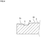
Fig. 4] Fig. 4 is a cross-sectional view of a half member according to another embodiment of the present invention taken along line II(C)-II(C). - Embodiments of the invention are described below.
Fig. 1 is a front view of a slidingbearing 1, with a vertical direction of the sheet defined as an upper and lower direction, and a direction between a closer side and a farther side of the sheet defined as an axial direction (front and rear direction). - First of all,
half members 2 as parts of the sliding bearing 1 according to an embodiment of the present invention are described with reference toFig.1 andFig. 2 . - The sliding
bearing 1 is a cylindrical member, and is applied to a sliding bearing structure of acrankshaft 11 of an engine as illustrated inFig. 1 . The sliding bearing 1 includes twohalf members half members half members bearing 1 is supporting thecrankshaft 11, a predetermined gap is formed, and lubricant oil is supplied into the gap through an unillustrated oil path. -
Fig. 2(A) illustrates thehalf members 2 on upper and lower sides. In the present embodiment, a rotational direction of thecrankshaft 11 corresponds to the clockwise direction in front view as indicated by an arrow inFig. 1 . A bearing angle ω is 0° at a right end position inFig. 2(B) , and increases along the counterclockwise direction inFig. 2(B) . More specifically, the bearing angle ω inFig. 2(B) is defined as 180° at a left end position, and as 270° at a lower end position. - The
half member 2 on the upper side has an inner circumference provided circumferentially with a groove that has a round hole at the center, and has the joining surfaces on the left and the right sides. - The
lower half member 2 has an inner circumference with axial direction ends provided withnarrow grooves 3. Acoating layer 23 is provided to an inner peripheral surface of thelower half member 2 as illustrated inFig. 2(C) . - The
coating layer 23 includes at least one of molybdenum disulfide, graphite, carbon, polytetrafluoroethylene, boron nitride, tungsten disulfide, and fluorine-based resin. - A
peripheral section 2a is formed on a surface on the outer side of each of thenarrow grooves 3 in the axial direction, and is formed to have a height h from an outer peripheral surface of thehalf member 2 that is shorter than a height D of a contact surface from the outer peripheral surface of thehalf member 2. Thus, theperipheral section 2a formed outward in the axial direction is formed to be one step lower than the contact surface, adjacent to theperipheral section 2a, to be in contact with thecrankshaft 11. - The
narrow grooves 3 are described with reference toFig. 2(B) and Fig. 2(C) . - The
narrow grooves 3 are provided on thelower half member 2. In the present embodiment, twonarrow grooves 3 are arranged in parallel in the axial direction. More specifically, thenarrow grooves 3 extend circumferentially to a bearing angle ω2 in a direction in which the bearing angle ω increases (counterclockwise direction) from a position (with the bearing angle ω of (ω1) separated from the joining surface (with the bearing angle ω of 180°) at a downstream side of a rotational direction of thecrankshaft 11. Thelower half member 2 has a joining surface on the right side inFig. 2(B) as a joining surface at an upstream side of the rotational direction, and a joining surface on the left side inFig. 2(B) as the joining surface at the downstream side of the rotational direction. - The
narrow grooves 3 are formed to have a width w as illustrated inFig. 2(C) . - The
narrow grooves 3 are also formed to have a depth d shorter than the height D of the contact surface from the outer peripheral surface of thehalf member 2. The depth d to abottom surface 3a of thenarrow groove 3 changes from one end of thenarrow groove 3 in the longitudinal direction toward the other end as illustrated inFig. 3(A) . - As illustrated in
Fig. 2(B) andFig. 3 , aninclined part 3b is provided to a downstream side end, in the rotational direction, of each of thenarrow grooves 3. Theinclined part 3b is inclined toward an inner peripheral side when approaching the downstream side, and has a curved shape that is more sharply inclined at a portion more on the downstream side as viewed in a cross-sectional view (cross-sectional view taken along the line II(B)-II(B)) in parallel with the longitudinal direction. - An
inclined part 3c is provided to an upstream side end, in the rotational direction, of each of thenarrow grooves 3. Theinclined part 3c is inclined toward an inner peripheral side when approaching the downstream side, and has a curved shape that is more sharply inclined at a portion more on the upstream side as viewed in the cross-sectional view (cross-sectional view taken along the line II(B)-II(B)) in parallel with the longitudinal direction. - As illustrated in
Fig. 3(A) and Fig. 3(B) ,coating layers inclined part 3b and theinclined part 3c. - The
coating layer 23 includes molybdenum disulfide, graphite, carbon, polytetrafluoroethylene, boron nitride, tungsten disulfide, or fluorine-based resin. Thecoating layer 23 with this configuration has lipophilicity. - Foreign objects such as dust that has entered between the
crankshaft 11 and the inner peripheral surface might enter into thenarrow groove 3. The foreign objects that have thus entered are likely to be accumulated on theinclined part 3b or theinclined part 3c. The coating layers 23a and 23a, provided on the inner peripheral surfaces of theinclined part 3b and theinclined part 3c, have low hardness. Thus, the foreign objects such as dust can be buried and captured in the coating layers 23a and 23a. A larger amount of foreign objects is likely to accumulate on theinclined part 3b than on theinclined part 3c. Thus, thecoating layer 23a may be provided only on theinclined part 3b. With this configuration, a surface of thecrankshaft 11 and the inner peripheral surface of the slidingbearing 1 can be prevented from being damaged (seized or scratched) by the foreign objects. - With the
peripheral section 2a formed to be one step lower than the contact surface, adjacent to theperipheral section 2a, to be in contact with thecrankshaft 11, theperipheral section 2a is less likely to be in contact with thecrankshaft 11 inclined to be in a state of being in contact with one axial direction end (partial contact state), and thus can be prevented from being damaged. - The
peripheral section 2a is formed to be one step below the contact surface adjacent to theperipheral section 2a. Thus, a larger gap is achieved in the end portion of the slidingbearing 1 in the axial direction. Thus, the quantity of lead-in oil is increased and the total quantity of outflow oil is reduced. - Coating layers 23b and 23b are provided on the upstream side end and the downstream side end of the
peripheral section 2a in the inner peripheral surface. - The coating layers 23b and 23b, provided on the inner peripheral surfaces of the
peripheral section 2a, have low hardness. Thus, the foreign objects such as dust can be buried and captured in the coating layers 23b and 23b. With this configuration, the surface of thecrankshaft 11 and the inner peripheral surface of the slidingbearing 1 can be prevented from being damaged by the foreign objects. - With the
narrow grooves 3 according to the present embodiment, a smaller FMEP is achieved. An especially smaller FMEP is achieved in a region with a low engine speed. The FMEP is a value indicating friction characteristics. Smaller FMEP leads to a lower friction. For example, at the timing of engine cold start, FMEP is reduced and the friction is reduced. - The coating layers 23 are formed by being applied on the inner peripheral surfaces of the
half members 2. Thecoating layer 23 is formed to cover the inner side end in the axial direction as illustrated inFig. 3(A) . More specifically, thecoating layer 23 is applied in an area between an end and an intermediate portion of a side surface of thenarrow groove 3 on the inner side in the axial direction. This configuration where thecoating layer 23 covers the inner side end of thenarrow groove 3 in the axial direction can achieve a smaller friction between the inner side end of thenarrow groove 3 in the axial direction and thecrank shaft 11 when thecrankshaft 11 is inclined to be in a state of being in contact with one end in the axial direction (partial contact state). - The
coating layer 23 may be formed to entirely cover thenarrow groove 3 as illustrated inFig. 4 . This configuration can achieve a smaller friction between the inner side end of thenarrow groove 3 in the axial direction and thecrank shaft 11 when thecrankshaft 11 is inclined to be in a state of being in contact with one end in the axial direction (partial contact state). - As described above, the sliding
bearing 1 includes vertically-arrangedhalf members narrow groove 3 is provided circumferentially to the axial direction end of thelower half member 2 at the downstream side of the rotational direction. Theinclined part 3b, which is inclined toward the inner peripheral side when approaching the downstream side, is provided to the downstream side end, in the rotational direction, of thenarrow groove 3. Thecoating layer 23a is provided to at least part of the inner peripheral surface of theinclined part 3b. - With this configuration, the
narrow groove 3 is provided without hindering generation of oil film pressure, whereby a friction reducing effect can be obtained with a smaller sliding area and the total quantity of outflow oil can be reduced. Theinclined part 3b is provided to the downstream side end, in the rotational direction, of thenarrow groove 3, and thecoating layer 23a is provided to the inner peripheral surface of theinclined part 3b. Thus, the foreign objects accumulated on the downstream side end of thenarrow groove 3 in the rotational direction are captured bycoating layer 23a. Thus, the surface of thecrank shaft 11 and the inner peripheral surface of the slidingbearing 1 can be prevented from being damaged by the foreign objects. - The
inclined part 3c, which is inclined toward the inner peripheral side when approaching an upstream side, is provided to the upstream side end, in the rotational direction, of thenarrow groove 3. Thecoating layer 23a is provided to at least part of the inner peripheral surface of theinclined part 3c. - With this configuration, the foreign objects accumulated on the upstream side end of the
narrow groove 3 in the rotational direction are captured bycoating layer 23a. Thus, the surface of thecrank shaft 11 and the inner peripheral surface of the slidingbearing 1 can be prevented from being damaged by the foreign objects. - The
coating layer 23 includes at least one of molybdenum disulfide, graphite, carbon, polytetrafluoroethylene, boron nitride, tungsten disulfide, and fluorine-based resin. - This configuration can achieve higher conformability with respect to lubricant oil, whereby the quantity of the outflow oil can be reduced. Thus, the total quantity of the outflow oil can be reduced. The
coating layer 23a provided to theinclined part 3b of the downstream side end and theinclined part 3c of the upstream side end in thenarrow groove 3 includes at least one of molybdenum disulfide, graphite, carbon, polytetrafluoroethylene, boron nitride, tungsten disulfide, and fluorine-based resin. Thus, low hardness facilitating the capturing of the foreign objects such as dust can be achieved. - The present invention can be applied to a technique for a sliding bearing, and can be applied to a technique for a sliding bearing including vertically-arranged half members obtained by halving a cylinder in parallel with an axial direction of the cylinder.
-
- 1
- Sliding bearing
- 2
- Half member
- 2a
- Peripheral section
- 3
- Narrow groove
- 3a
- Bottom surface
- 3b
- Inclined part
- 3c
- Inclined part
- 11
- Crankshaft
- 23, 23a
- Coating layer
Claims (3)
- A sliding bearing comprising: vertically-arranged half members obtained by halving a cylinder in parallel with an axial direction of the cylinder, wherein a narrow groove is provided circumferentially to an axial direction end of the lower half member at a downstream side of a rotational direction,
an inclined part that is inclined toward an inner peripheral side when approaching the downstream side is provided to a downstream side end, in the rotational direction, of the narrow groove, and a coating layer is provided to at least part of an inner peripheral surface of the inclined part. - The sliding bearing according to claim 1, wherein an inclined part that is inclined toward an inner peripheral side when approaching an upstream side is provided to an upstream side end, in the rotational direction, of the narrow groove, and a coating layer is provided to at least part of an inner peripheral surface of the inclined part.
- The sliding bearing according to claim 1 or 2, wherein the coating layer includes at least one of molybdenum disulfide, graphite, carbon, polytetrafluoroethylene, boron nitride, tungsten disulfide, and fluorine-based resin.
Applications Claiming Priority (2)
| Application Number | Priority Date | Filing Date | Title |
|---|---|---|---|
| JP2015039118A JP6314103B2 (en) | 2015-02-27 | 2015-02-27 | Plain bearing |
| PCT/JP2016/055950 WO2016136995A1 (en) | 2015-02-27 | 2016-02-26 | Sliding bearing |
Publications (2)
| Publication Number | Publication Date |
|---|---|
| EP3263929A1 true EP3263929A1 (en) | 2018-01-03 |
| EP3263929A4 EP3263929A4 (en) | 2018-09-12 |
Family
ID=56788568
Family Applications (1)
| Application Number | Title | Priority Date | Filing Date |
|---|---|---|---|
| EP16755739.6A Withdrawn EP3263929A4 (en) | 2015-02-27 | 2016-02-26 | Sliding bearing |
Country Status (6)
| Country | Link |
|---|---|
| US (1) | US10054162B2 (en) |
| EP (1) | EP3263929A4 (en) |
| JP (1) | JP6314103B2 (en) |
| KR (1) | KR20170121259A (en) |
| CN (1) | CN107407331A (en) |
| WO (1) | WO2016136995A1 (en) |
Families Citing this family (2)
| Publication number | Priority date | Publication date | Assignee | Title |
|---|---|---|---|---|
| JP2019108923A (en) * | 2017-12-18 | 2019-07-04 | トヨタ自動車株式会社 | Thrust bearing and bearing device |
| JP2020045925A (en) * | 2018-09-14 | 2020-03-26 | 大豊工業株式会社 | Plain bearing |
Family Cites Families (20)
| Publication number | Priority date | Publication date | Assignee | Title |
|---|---|---|---|---|
| US4597676A (en) * | 1984-04-30 | 1986-07-01 | General Electric Company | Hybrid bearing |
| GB0010542D0 (en) | 2000-05-03 | 2000-06-21 | Dana Corp | Bearings |
| JP2004347050A (en) * | 2003-05-23 | 2004-12-09 | Honda Motor Co Ltd | Wear plate |
| DE102005055366A1 (en) * | 2004-12-10 | 2006-06-14 | Mahle International Gmbh | Connecting rod for an internal combustion engine and method for coating its sliding bearing surfaces |
| DE102006013399A1 (en) | 2005-12-21 | 2007-07-05 | Mahle International Gmbh | Connecting rod for internal combustion engine, has small connecting rod eye for holding piston pin and large connecting rod eye for holding crank pin whereby bore is provided with coating having resin with solid lubricant particles |
| JP2008014454A (en) * | 2006-07-07 | 2008-01-24 | Daido Metal Co Ltd | Sliding bearing |
| DE102007058744B4 (en) * | 2007-12-05 | 2019-06-06 | Federal-Mogul Wiesbaden Gmbh | Slide bearing shell and bearing arrangement |
| JP2011094746A (en) * | 2009-10-30 | 2011-05-12 | Taiho Kogyo Co Ltd | Slide bearing |
| GB201002309D0 (en) * | 2010-02-11 | 2010-03-31 | Mahle Int Gmbh | Bearing |
| JP2011208740A (en) * | 2010-03-30 | 2011-10-20 | Daido Metal Co Ltd | Slide bearing |
| JP2012047276A (en) * | 2010-08-27 | 2012-03-08 | Taiho Kogyo Co Ltd | Sliding bearing and method for manufacturing the same |
| DE102011005467B4 (en) | 2011-03-11 | 2016-04-28 | Federal-Mogul Wiesbaden Gmbh | Plain bearing shell with a collecting groove |
| CN102345678B (en) * | 2011-06-17 | 2013-04-10 | 浙江长盛滑动轴承股份有限公司 | Three layer composite self-lubricating sliding bearing with modified polyimide wear layer and preparation method thereof |
| JP5132806B1 (en) * | 2011-09-29 | 2013-01-30 | 大同メタル工業株式会社 | Plain bearing |
| JP5895638B2 (en) * | 2012-03-21 | 2016-03-30 | 大豊工業株式会社 | Plain bearing |
| JP5939928B2 (en) | 2012-08-06 | 2016-06-22 | 大同メタル工業株式会社 | Plain bearing |
| JP6123985B2 (en) | 2012-12-25 | 2017-05-10 | 大豊工業株式会社 | Half thrust bearing |
| JP5837896B2 (en) * | 2013-03-21 | 2015-12-24 | 大豊工業株式会社 | Plain bearing |
| JP6096689B2 (en) | 2013-04-26 | 2017-03-15 | 大豊工業株式会社 | Plain bearing |
| JP6025655B2 (en) * | 2013-05-16 | 2016-11-16 | 大豊工業株式会社 | Manufacturing method of plain bearing |
-
2015
- 2015-02-27 JP JP2015039118A patent/JP6314103B2/en active Active
-
2016
- 2016-02-26 WO PCT/JP2016/055950 patent/WO2016136995A1/en not_active Ceased
- 2016-02-26 US US15/553,814 patent/US10054162B2/en not_active Expired - Fee Related
- 2016-02-26 CN CN201680012652.4A patent/CN107407331A/en active Pending
- 2016-02-26 KR KR1020177027289A patent/KR20170121259A/en not_active Ceased
- 2016-02-26 EP EP16755739.6A patent/EP3263929A4/en not_active Withdrawn
Also Published As
| Publication number | Publication date |
|---|---|
| US10054162B2 (en) | 2018-08-21 |
| CN107407331A (en) | 2017-11-28 |
| US20180038416A1 (en) | 2018-02-08 |
| JP2016161018A (en) | 2016-09-05 |
| KR20170121259A (en) | 2017-11-01 |
| JP6314103B2 (en) | 2018-04-18 |
| WO2016136995A1 (en) | 2016-09-01 |
| EP3263929A4 (en) | 2018-09-12 |
Similar Documents
| Publication | Publication Date | Title |
|---|---|---|
| US9958007B2 (en) | Slide bearing | |
| JP2014224601A (en) | Slide bearing | |
| JP2014126199A (en) | Half-split thrust bearing | |
| JP5837896B2 (en) | Plain bearing | |
| US9004767B2 (en) | Half bearing and plain bearing | |
| EP3263930A1 (en) | Slide bearing | |
| EP3263929A1 (en) | Sliding bearing | |
| WO2017090287A1 (en) | Half bearing | |
| US9933007B2 (en) | Sliding bearing | |
| EP3263931A1 (en) | Manufacturing method for sliding bearing, and sliding bearing | |
| CN105008733B (en) | Slide bearing | |
| JP6134636B2 (en) | Plain bearing | |
| US20180119739A1 (en) | Sliding bearing manufacturing method and sliding bearing | |
| JP6634200B2 (en) | Half plain bearing for the upper side of the main bearing of an internal combustion engine | |
| EP3263928A1 (en) | Sliding bearing | |
| JP2015197215A (en) | slide bearing | |
| JP2016161018A5 (en) | ||
| JP2015183826A (en) | bearing member | |
| JP2015169267A (en) | Crankshaft support structure | |
| WO2017104795A1 (en) | Slide bearing | |
| JP2015187457A (en) | Bearing member | |
| EP3263923A1 (en) | Manufacturing method for sliding bearing, and sliding bearing | |
| JP2015183827A (en) | Bearing member | |
| JP2017110762A (en) | Plain bearing | |
| JP2017110761A (en) | Slide bearing |
Legal Events
| Date | Code | Title | Description |
|---|---|---|---|
| STAA | Information on the status of an ep patent application or granted ep patent |
Free format text: STATUS: THE INTERNATIONAL PUBLICATION HAS BEEN MADE |
|
| PUAI | Public reference made under article 153(3) epc to a published international application that has entered the european phase |
Free format text: ORIGINAL CODE: 0009012 |
|
| STAA | Information on the status of an ep patent application or granted ep patent |
Free format text: STATUS: REQUEST FOR EXAMINATION WAS MADE |
|
| 17P | Request for examination filed |
Effective date: 20170925 |
|
| AK | Designated contracting states |
Kind code of ref document: A1 Designated state(s): AL AT BE BG CH CY CZ DE DK EE ES FI FR GB GR HR HU IE IS IT LI LT LU LV MC MK MT NL NO PL PT RO RS SE SI SK SM TR |
|
| AX | Request for extension of the european patent |
Extension state: BA ME |
|
| DAV | Request for validation of the european patent (deleted) | ||
| DAX | Request for extension of the european patent (deleted) | ||
| A4 | Supplementary search report drawn up and despatched |
Effective date: 20180724 |
|
| RIC1 | Information provided on ipc code assigned before grant |
Ipc: F16C 17/02 20060101ALI20180718BHEP Ipc: F16C 9/02 20060101ALI20180718BHEP Ipc: F16C 33/10 20060101ALI20180718BHEP Ipc: F16C 33/04 20060101ALI20180718BHEP Ipc: F16C 33/08 20060101AFI20180718BHEP |
|
| RA4 | Supplementary search report drawn up and despatched (corrected) |
Effective date: 20180724 |
|
| RIC1 | Information provided on ipc code assigned before grant |
Ipc: F16C 33/08 20060101AFI20180804BHEP Ipc: F16C 33/10 20060101ALI20180804BHEP Ipc: F16C 33/04 20060101ALI20180804BHEP Ipc: F16C 9/02 20060101ALI20180804BHEP Ipc: F16C 17/02 20060101ALI20180804BHEP |
|
| GRAP | Despatch of communication of intention to grant a patent |
Free format text: ORIGINAL CODE: EPIDOSNIGR1 |
|
| STAA | Information on the status of an ep patent application or granted ep patent |
Free format text: STATUS: GRANT OF PATENT IS INTENDED |
|
| INTG | Intention to grant announced |
Effective date: 20190329 |
|
| STAA | Information on the status of an ep patent application or granted ep patent |
Free format text: STATUS: THE APPLICATION IS DEEMED TO BE WITHDRAWN |
|
| 18D | Application deemed to be withdrawn |
Effective date: 20190809 |