EP3263909A1 - Method of manufacturing turbocharger - Google Patents
Method of manufacturing turbocharger Download PDFInfo
- Publication number
- EP3263909A1 EP3263909A1 EP15883267.5A EP15883267A EP3263909A1 EP 3263909 A1 EP3263909 A1 EP 3263909A1 EP 15883267 A EP15883267 A EP 15883267A EP 3263909 A1 EP3263909 A1 EP 3263909A1
- Authority
- EP
- European Patent Office
- Prior art keywords
- housing
- impeller
- abradable
- coating
- abradable material
- Prior art date
- Legal status (The legal status is an assumption and is not a legal conclusion. Google has not performed a legal analysis and makes no representation as to the accuracy of the status listed.)
- Granted
Links
Images





Classifications
-
- F—MECHANICAL ENGINEERING; LIGHTING; HEATING; WEAPONS; BLASTING
- F04—POSITIVE - DISPLACEMENT MACHINES FOR LIQUIDS; PUMPS FOR LIQUIDS OR ELASTIC FLUIDS
- F04D—NON-POSITIVE-DISPLACEMENT PUMPS
- F04D29/00—Details, component parts, or accessories
- F04D29/18—Rotors
- F04D29/22—Rotors specially for centrifugal pumps
- F04D29/2205—Conventional flow pattern
- F04D29/2222—Construction and assembly
- F04D29/2227—Construction and assembly for special materials
-
- C—CHEMISTRY; METALLURGY
- C23—COATING METALLIC MATERIAL; COATING MATERIAL WITH METALLIC MATERIAL; CHEMICAL SURFACE TREATMENT; DIFFUSION TREATMENT OF METALLIC MATERIAL; COATING BY VACUUM EVAPORATION, BY SPUTTERING, BY ION IMPLANTATION OR BY CHEMICAL VAPOUR DEPOSITION, IN GENERAL; INHIBITING CORROSION OF METALLIC MATERIAL OR INCRUSTATION IN GENERAL
- C23C—COATING METALLIC MATERIAL; COATING MATERIAL WITH METALLIC MATERIAL; SURFACE TREATMENT OF METALLIC MATERIAL BY DIFFUSION INTO THE SURFACE, BY CHEMICAL CONVERSION OR SUBSTITUTION; COATING BY VACUUM EVAPORATION, BY SPUTTERING, BY ION IMPLANTATION OR BY CHEMICAL VAPOUR DEPOSITION, IN GENERAL
- C23C24/00—Coating starting from inorganic powder
- C23C24/02—Coating starting from inorganic powder by application of pressure only
- C23C24/04—Impact or kinetic deposition of particles
-
- C—CHEMISTRY; METALLURGY
- C23—COATING METALLIC MATERIAL; COATING MATERIAL WITH METALLIC MATERIAL; CHEMICAL SURFACE TREATMENT; DIFFUSION TREATMENT OF METALLIC MATERIAL; COATING BY VACUUM EVAPORATION, BY SPUTTERING, BY ION IMPLANTATION OR BY CHEMICAL VAPOUR DEPOSITION, IN GENERAL; INHIBITING CORROSION OF METALLIC MATERIAL OR INCRUSTATION IN GENERAL
- C23C—COATING METALLIC MATERIAL; COATING MATERIAL WITH METALLIC MATERIAL; SURFACE TREATMENT OF METALLIC MATERIAL BY DIFFUSION INTO THE SURFACE, BY CHEMICAL CONVERSION OR SUBSTITUTION; COATING BY VACUUM EVAPORATION, BY SPUTTERING, BY ION IMPLANTATION OR BY CHEMICAL VAPOUR DEPOSITION, IN GENERAL
- C23C24/00—Coating starting from inorganic powder
- C23C24/08—Coating starting from inorganic powder by application of heat or pressure and heat
-
- C—CHEMISTRY; METALLURGY
- C23—COATING METALLIC MATERIAL; COATING MATERIAL WITH METALLIC MATERIAL; CHEMICAL SURFACE TREATMENT; DIFFUSION TREATMENT OF METALLIC MATERIAL; COATING BY VACUUM EVAPORATION, BY SPUTTERING, BY ION IMPLANTATION OR BY CHEMICAL VAPOUR DEPOSITION, IN GENERAL; INHIBITING CORROSION OF METALLIC MATERIAL OR INCRUSTATION IN GENERAL
- C23C—COATING METALLIC MATERIAL; COATING MATERIAL WITH METALLIC MATERIAL; SURFACE TREATMENT OF METALLIC MATERIAL BY DIFFUSION INTO THE SURFACE, BY CHEMICAL CONVERSION OR SUBSTITUTION; COATING BY VACUUM EVAPORATION, BY SPUTTERING, BY ION IMPLANTATION OR BY CHEMICAL VAPOUR DEPOSITION, IN GENERAL
- C23C4/00—Coating by spraying the coating material in the molten state, e.g. by flame, plasma or electric discharge
- C23C4/02—Pretreatment of the material to be coated, e.g. for coating on selected surface areas
-
- C—CHEMISTRY; METALLURGY
- C23—COATING METALLIC MATERIAL; COATING MATERIAL WITH METALLIC MATERIAL; CHEMICAL SURFACE TREATMENT; DIFFUSION TREATMENT OF METALLIC MATERIAL; COATING BY VACUUM EVAPORATION, BY SPUTTERING, BY ION IMPLANTATION OR BY CHEMICAL VAPOUR DEPOSITION, IN GENERAL; INHIBITING CORROSION OF METALLIC MATERIAL OR INCRUSTATION IN GENERAL
- C23C—COATING METALLIC MATERIAL; COATING MATERIAL WITH METALLIC MATERIAL; SURFACE TREATMENT OF METALLIC MATERIAL BY DIFFUSION INTO THE SURFACE, BY CHEMICAL CONVERSION OR SUBSTITUTION; COATING BY VACUUM EVAPORATION, BY SPUTTERING, BY ION IMPLANTATION OR BY CHEMICAL VAPOUR DEPOSITION, IN GENERAL
- C23C4/00—Coating by spraying the coating material in the molten state, e.g. by flame, plasma or electric discharge
- C23C4/04—Coating by spraying the coating material in the molten state, e.g. by flame, plasma or electric discharge characterised by the coating material
- C23C4/10—Oxides, borides, carbides, nitrides or silicides; Mixtures thereof
-
- F—MECHANICAL ENGINEERING; LIGHTING; HEATING; WEAPONS; BLASTING
- F04—POSITIVE - DISPLACEMENT MACHINES FOR LIQUIDS; PUMPS FOR LIQUIDS OR ELASTIC FLUIDS
- F04D—NON-POSITIVE-DISPLACEMENT PUMPS
- F04D13/00—Pumping installations or systems
- F04D13/02—Units comprising pumps and their driving means
- F04D13/021—Units comprising pumps and their driving means containing a coupling
-
- F—MECHANICAL ENGINEERING; LIGHTING; HEATING; WEAPONS; BLASTING
- F04—POSITIVE - DISPLACEMENT MACHINES FOR LIQUIDS; PUMPS FOR LIQUIDS OR ELASTIC FLUIDS
- F04D—NON-POSITIVE-DISPLACEMENT PUMPS
- F04D17/00—Radial-flow pumps, e.g. centrifugal pumps; Helico-centrifugal pumps
- F04D17/08—Centrifugal pumps
- F04D17/10—Centrifugal pumps for compressing or evacuating
-
- F—MECHANICAL ENGINEERING; LIGHTING; HEATING; WEAPONS; BLASTING
- F04—POSITIVE - DISPLACEMENT MACHINES FOR LIQUIDS; PUMPS FOR LIQUIDS OR ELASTIC FLUIDS
- F04D—NON-POSITIVE-DISPLACEMENT PUMPS
- F04D25/00—Pumping installations or systems
- F04D25/02—Units comprising pumps and their driving means
- F04D25/024—Units comprising pumps and their driving means the driving means being assisted by a power recovery turbine
-
- F—MECHANICAL ENGINEERING; LIGHTING; HEATING; WEAPONS; BLASTING
- F04—POSITIVE - DISPLACEMENT MACHINES FOR LIQUIDS; PUMPS FOR LIQUIDS OR ELASTIC FLUIDS
- F04D—NON-POSITIVE-DISPLACEMENT PUMPS
- F04D27/00—Control, e.g. regulation, of pumps, pumping installations or pumping systems specially adapted for elastic fluids
- F04D27/02—Surge control
- F04D27/0207—Surge control by bleeding, bypassing or recycling fluids
- F04D27/0215—Arrangements therefor, e.g. bleed or by-pass valves
-
- F—MECHANICAL ENGINEERING; LIGHTING; HEATING; WEAPONS; BLASTING
- F04—POSITIVE - DISPLACEMENT MACHINES FOR LIQUIDS; PUMPS FOR LIQUIDS OR ELASTIC FLUIDS
- F04D—NON-POSITIVE-DISPLACEMENT PUMPS
- F04D29/00—Details, component parts, or accessories
- F04D29/02—Selection of particular materials
- F04D29/023—Selection of particular materials especially adapted for elastic fluid pumps
-
- F—MECHANICAL ENGINEERING; LIGHTING; HEATING; WEAPONS; BLASTING
- F04—POSITIVE - DISPLACEMENT MACHINES FOR LIQUIDS; PUMPS FOR LIQUIDS OR ELASTIC FLUIDS
- F04D—NON-POSITIVE-DISPLACEMENT PUMPS
- F04D29/00—Details, component parts, or accessories
- F04D29/08—Sealings
- F04D29/16—Sealings between pressure and suction sides
- F04D29/161—Sealings between pressure and suction sides especially adapted for elastic fluid pumps
- F04D29/162—Sealings between pressure and suction sides especially adapted for elastic fluid pumps of a centrifugal flow wheel
-
- F—MECHANICAL ENGINEERING; LIGHTING; HEATING; WEAPONS; BLASTING
- F04—POSITIVE - DISPLACEMENT MACHINES FOR LIQUIDS; PUMPS FOR LIQUIDS OR ELASTIC FLUIDS
- F04D—NON-POSITIVE-DISPLACEMENT PUMPS
- F04D29/00—Details, component parts, or accessories
- F04D29/26—Rotors specially for elastic fluids
- F04D29/28—Rotors specially for elastic fluids for centrifugal or helico-centrifugal pumps for radial-flow or helico-centrifugal pumps
- F04D29/289—Rotors specially for elastic fluids for centrifugal or helico-centrifugal pumps for radial-flow or helico-centrifugal pumps having provision against erosion or for dust-separation
-
- F—MECHANICAL ENGINEERING; LIGHTING; HEATING; WEAPONS; BLASTING
- F04—POSITIVE - DISPLACEMENT MACHINES FOR LIQUIDS; PUMPS FOR LIQUIDS OR ELASTIC FLUIDS
- F04D—NON-POSITIVE-DISPLACEMENT PUMPS
- F04D29/00—Details, component parts, or accessories
- F04D29/26—Rotors specially for elastic fluids
- F04D29/28—Rotors specially for elastic fluids for centrifugal or helico-centrifugal pumps for radial-flow or helico-centrifugal pumps
- F04D29/30—Vanes
-
- F—MECHANICAL ENGINEERING; LIGHTING; HEATING; WEAPONS; BLASTING
- F04—POSITIVE - DISPLACEMENT MACHINES FOR LIQUIDS; PUMPS FOR LIQUIDS OR ELASTIC FLUIDS
- F04D—NON-POSITIVE-DISPLACEMENT PUMPS
- F04D29/00—Details, component parts, or accessories
- F04D29/40—Casings; Connections of working fluid
- F04D29/42—Casings; Connections of working fluid for radial or helico-centrifugal pumps
- F04D29/4206—Casings; Connections of working fluid for radial or helico-centrifugal pumps especially adapted for elastic fluid pumps
-
- F—MECHANICAL ENGINEERING; LIGHTING; HEATING; WEAPONS; BLASTING
- F04—POSITIVE - DISPLACEMENT MACHINES FOR LIQUIDS; PUMPS FOR LIQUIDS OR ELASTIC FLUIDS
- F04D—NON-POSITIVE-DISPLACEMENT PUMPS
- F04D29/00—Details, component parts, or accessories
- F04D29/60—Mounting; Assembling; Disassembling
- F04D29/62—Mounting; Assembling; Disassembling of radial or helico-centrifugal pumps
- F04D29/622—Adjusting the clearances between rotary and stationary parts
-
- F—MECHANICAL ENGINEERING; LIGHTING; HEATING; WEAPONS; BLASTING
- F01—MACHINES OR ENGINES IN GENERAL; ENGINE PLANTS IN GENERAL; STEAM ENGINES
- F01D—NON-POSITIVE DISPLACEMENT MACHINES OR ENGINES, e.g. STEAM TURBINES
- F01D11/00—Preventing or minimising internal leakage of working-fluid, e.g. between stages
- F01D11/08—Preventing or minimising internal leakage of working-fluid, e.g. between stages for sealing space between rotor blade tips and stator
- F01D11/12—Preventing or minimising internal leakage of working-fluid, e.g. between stages for sealing space between rotor blade tips and stator using a rubstrip, e.g. erodible. deformable or resiliently-biased part
- F01D11/122—Preventing or minimising internal leakage of working-fluid, e.g. between stages for sealing space between rotor blade tips and stator using a rubstrip, e.g. erodible. deformable or resiliently-biased part with erodable or abradable material
-
- F—MECHANICAL ENGINEERING; LIGHTING; HEATING; WEAPONS; BLASTING
- F05—INDEXING SCHEMES RELATING TO ENGINES OR PUMPS IN VARIOUS SUBCLASSES OF CLASSES F01-F04
- F05D—INDEXING SCHEME FOR ASPECTS RELATING TO NON-POSITIVE-DISPLACEMENT MACHINES OR ENGINES, GAS-TURBINES OR JET-PROPULSION PLANTS
- F05D2220/00—Application
- F05D2220/40—Application in turbochargers
-
- F—MECHANICAL ENGINEERING; LIGHTING; HEATING; WEAPONS; BLASTING
- F05—INDEXING SCHEMES RELATING TO ENGINES OR PUMPS IN VARIOUS SUBCLASSES OF CLASSES F01-F04
- F05D—INDEXING SCHEME FOR ASPECTS RELATING TO NON-POSITIVE-DISPLACEMENT MACHINES OR ENGINES, GAS-TURBINES OR JET-PROPULSION PLANTS
- F05D2240/00—Components
- F05D2240/20—Rotors
- F05D2240/30—Characteristics of rotor blades, i.e. of any element transforming dynamic fluid energy to or from rotational energy and being attached to a rotor
- F05D2240/307—Characteristics of rotor blades, i.e. of any element transforming dynamic fluid energy to or from rotational energy and being attached to a rotor related to the tip of a rotor blade
Definitions
- the present invention relates to a method of manufacturing a supercharger including a compressor having an impeller configured to rotate according to the rotational force of a turbine to compress air.
- a turbine rotationally drives according to exhaust gas of an engine, and an impeller of a centrifugal compressor rotates according to the rotational force of the turbine. Compressed air compressed by the centrifugal compressor is fed into the engine.
- a clearance gap is provided between the housing and the impeller. This can prevent contact between the housing and the impeller that is caused by the influence of heat expansion and vibration in operations, and component tolerance.
- An abradable layer narrows a clearance gap between the housing and the impeller. The performance can be thereby enhanced while reliability is assured because the impeller is not damaged even if the impeller comes into contact with the abradable layer.
- the aforementioned PTL 2 discloses a method of attaching a synthetic-resin slide member to a housing by adhesion. Nevertheless, productivity degrades because a process of manufacturing the synthetic-resin slide member and an adhesion process are additionally required, and the number of components increases. In addition, it is necessary to separately manufacture the synthetic-resin slide members according to the shape of the housing or the impeller, so that the number of types of components also increases.
- the aforementioned PTL 3 discloses a method of closely adhering a molding die to the inner surface side of a housing, and injecting synthetic resin into a space between the housing and the molding die. Using this method, a slide member is formed on the inner surface side of the housing through injection molding. Nevertheless, productivity is bad because it is necessary to change the molding die according to the shape of the housing or an impeller.
- the aforementioned PTL 1 discloses a method of forming the abradable coating layer on the inner periphery of the housing by spraying synthetic resin onto the inner periphery of the housing by means of thermal spraying. Nevertheless, in the case of thermal spraying and spray coating, it is difficult to confine an application region. In addition, it is also difficult to adjust a coating thickness. Thus, masking of regions surrounding the application region, and post-processing or finishing for adjusting a coating thickness are generally required, which degrades productivity.
- the present invention has been contrived in view of such circumstances, and the object of the present invention is to provide a method of manufacturing a supercharger that can promptly and easily form an abradable layer in the supercharger.
- a method of manufacturing a supercharger according to the present invention employs the following solutions.
- a method of manufacturing a supercharger is a method of manufacturing a supercharger including a turbine configured to rotationally drive, and a compressor having an impeller configured to rotate according to rotational force of the turbine and a housing configured to store the impeller, and the method includes a process of applying coating of an abradable material which is to form an abradable layer when being solidified, only to a predetermined range on either one of surfaces of the impeller and the housing via which the impeller and the housing face.
- the coating of the abradable material is applied onto the surface of the impeller or the surface of the housing, it is unnecessary to additionally manufacture an abradable material as a component, and to perform changeover according to the shape of the impeller or the housing.
- adjustment of a coating thickness is generally easy, so that the post-processing and the finishing become unnecessary.
- the coating of the abradable material is applied onto an inner peripheral surface of the housing (a surface facing a tip portion of a blade of the impeller, or a surface facing an outer peripheral surface on an end plate side of the impeller), the tip portion of the blade of the impeller, or the outer peripheral surface on the end plate side of the impeller.
- coating of the abradable material is applied only to the predetermined range without applying masking.
- the coating of the abradable material is applied only to the predetermined range without applying masking, productivity can be enhanced.
- the coating is applied without performing masking, the abradable material wetly spreads on the surface of the impeller or the housing. This consequently causes a state in which no level difference is generated at an end portion of the abradable layer, unlike a case of applying masking.
- the separation of airflow on the surface of the impeller or the housing can be suppressed, and efficiency degradation of the supercharger can also be suppressed.
- coating of the abradable material is applied using a constant amount discharge nozzle, a brush, or a pad.
- the coating of the abradable material is applied in a state in which the abradable material is brought close to the surface of the impeller or the housing, or pressed against the surface of the impeller or the housing. It is therefore easy to form the abradable layer only in the predetermined range without applying masking.
- a process of forming a protruding portion or a recess portion on the surface of the impeller or the housing at a boundary of a region in which the abradable layer is to be formed, before the process of applying coating of the abradable material is further included.
- the protruding portion or the recess portion being formed on the surface of the impeller or the housing, it becomes difficult for the abradable material to spread excessively, and the abradable layer is surely applied to the predetermined range.
- the protruding portion or the recess portion desirably has such a height or a depth that a flow of air is not disturbed, and preferably has such a shape that the abradable layer and the impeller or the housing are smoothly connected.
- a process of increasing a roughness degree in an outside region of a region in which the abradable layer is to be formed, to be rougher than a roughness degree in the region in which the abradable layer is to be formed, before the process of applying coating of the abradable material is further included.
- the abradable material contains synthetic resin and fine particles having a self-lubricating property.
- coating of the abradable material is applied so that a density becomes lower on a surface side of the abradable layer than a density on a side of the impeller or a side of the housing, when the abradable material is solidified.
- an abradable layer can be promptly and easily formed in a supercharger.
- turbocharger (supercharger) according to a first embodiment of the present invention will be described below using Fig. 1 .
- a turbocharger 1 includes a turbine 2, a compressor 3, and a rotation shaft 4 coupled to the turbine 2 and the compressor 3.
- the turbine 2 rotationally drives according to exhaust gas from an engine, and an impeller 11 of the compressor 3 rotates according to the rotational force of the turbine 2. Air compressed by the compressor 3 is supplied to the engine.
- the turbine 2 is disposed on one end side of the rotation shaft 4, and includes an impeller 6, a housing 5, and the like.
- the impeller 6 includes a blade 7, and is coupled to the rotation shaft 4 to rotate around a shaft line.
- the housing 5 covers the impeller 6 from the outside, and a scroll passage 8 communicating the inside and the outside of the housing 5 is formed therein.
- the scroll passage 8 extends from an end portion (a leading edge portion 7a) on the outside in a radial direction of the blade 7, outward in the radial direction, and is formed into a ring shape around the shaft line of the rotation shaft 4.
- the exhaust gas is introduced into the impeller 6 from the scroll passage 8 to rotate the impeller 6 and the rotation shaft 4.
- a discharge port 9 opening on one end side of the shaft line of the rotation shaft 4 is formed in the housing 5. Exhaust gas having passed through the blade 7 is discharged to the outside of the housing 5 through the discharge port 9.
- the compressor 3 is a centrifugal compressor, for example, and is disposed on the other end side of the rotation shaft 4, and includes the impeller 11, a housing 10, and the like.
- the impeller 11 includes a blade 12, and is coupled to the rotation shaft 4 to rotate around the shaft line.
- the housing 10 covers the impeller 11 from the outside.
- a suction port 13 opening on the other end side of the shaft line of the rotation shaft 4 is formed in the housing 10. Air is introduced into the impeller 11 from the outside through the suction port 13. The rotational force of the impeller 6 of the turbine 2 is transmitted to the impeller 11 via the rotation shaft 4, so that the impeller 11 rotates. Air introduced from the outside is compressed by passing through the impeller 11.
- a compressor passage 14 communicating the inside and the outside of the housing 10 is formed in the housing 10, and the compressor passage 14 extends from an end portion (a trailing edge portion 12b) on the outside in a radial direction of the blade 12, outward in the radial direction, and is formed into a ring shape around the shaft line of the rotation shaft 4. Air compressed in the impeller 11 is introduced into the compressor passage 14 and is discharged to the outside of the housing 10.
- a bearing housing 15 is disposed between the turbine 2 and the compressor 3 to couple the turbine 2 and the compressor 3.
- the bearing housing 15 covers the rotation shaft 4 from the outside.
- a bearing 16 is provided in the bearing housing 15, and the bearing 16 supports the rotation shaft 4 so as to be rotatable with respect to the bearing housing 15.
- the bearing housing 15 is disposed so that an inner peripheral surface of the bearing housing 15 faces the impeller 11.
- An abradable layer 20 (refer to Fig. 2 ) is formed in a portion on the inner peripheral surface of the housing 10 of the compressor 3 that faces a side edge portion 12a of the blade 12.
- the abradable layer 20 is made of a material that is easily abraded even if the impeller 11 comes into contact with the material (hereinafter, referred to as an "abradable material”.), and is formed so as to narrow a clearance gap between the housing 10 and the blade 12 of the impeller 11.
- the formation of the abradable layer 20 narrows the clearance gap between the housing 10 and the impeller 11. As a result, the performance of the turbocharger 1 can be enhanced, and reliability can be assured because the impeller 11 is not damaged even if the impeller 11 comes into contact with the abradable layer 20.
- the abradable material is a material which is to form the abradable layer 20 when being solidified, and is synthetic resin, for example. Epoxy resin, polyamide, polyimide, and the like can be applied as synthetic resin.
- synthetic resin may contain fine particles having a self-lubricating property that are dispersed at a content rate of 5 wt% to 50 wt%.
- the fine particles have a grain size of 5 ⁇ m to 50 ⁇ m, and examples of the fine particles include molybdenum disulfide, polytetrafluoroethylene (PTFE), hexagonal boron nitride (hBN), graphite, and the like.
- the fine particles having a self-lubricating property being dispersed in the abradable material, the slidability of the solidified abradable layer 20 can be assured. As a result, frictional resistance caused when the impeller 11 comes into contact with the abradable layer 20 can be reduced, and damages to the impeller 11 can be prevented.
- the abradable layer 20 may have such a structure that a resin density becomes lower on a surface side of the abradable layer 20 than that on a surface adhering to the housing 10 being a base material.
- the abradable layer 20 tightly adheres to the housing 10 on the surface adhering to the housing 10, whereas the strength of the abradable layer 20 becomes lower on the surface side of the abradable layer 20.
- the abradable layer 20 becomes easily-abradable when the impeller 11 comes into contact with the abradable layer 20, and damages to the impeller 11 can be prevented.
- the aforementioned (1) to (3) methods may be implemented using the same synthetic resin, or may be implemented as a multilayered structure including two or more layers using different types of synthetic resin or different compositions.
- synthetic resin or a composition having high density and high adhesiveness is employed on the surface side adhering to the housing 10
- synthetic resin or a composition having high abradability is employed on the surface side of the abradable layer 20.
- the abradable layer 20 is formed by applying coating of the abradable material only to a predetermined range on the inner peripheral surface of the housing 10, without applying masking.
- a coating thickness can be adjusted in the application, so that post-processing or finishing for adjusting a coating thickness is not performed.
- the coating of the abradable material is applied onto the surface of the housing 10, it is unnecessary to additionally manufacture an abradable material as a component, and to perform changeover according to the shape of the impeller 11 or the housing 10. In addition, because the coating application can be performed in the same productive facilities regardless of the shape of the impeller 11 or the housing 10, productivity is high.
- the coating application can form the abradable layer 20 only in the predetermined range without applying masking. This can enhance productivity. Furthermore, in the coating application, adjustment of a coating thickness can be easily performed, so that the post-processing and the finishing become unnecessary. As a result, mass productivity becomes high, and the application can be performed inexpensively.
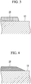
- the abradable layer 20 obtained immediately after the coating application is in a state as illustrated in Fig. 3 , and the abradable material wetly spreads on the surface of the housing 10 as time elapses.
- a masking tape 38 or the like is peeled off as illustrated in Fig. 15 . This generates a level difference at an end portion of an abradable layer 26.
- the present embodiment can cause a state in which no level difference is generated at an end portion of the abradable layer 20 as illustrated in Fig. 4 .
- the separation of airflow on the surface of the housing 10 can be suppressed, and efficiency degradation of the supercharger can also be suppressed.
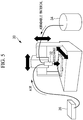
- a method of applying coating of the abradable material as illustrated in Fig. 5 , there is a method of using a constant amount discharge nozzle 32 of which the position is controlled by a three-axis robot 30 in three-axis directions.
- the housing 10 to which the abradable material is applied is not illustrated in Fig. 5 .
- the constant amount discharge nozzle 32 is provided in the three-axis robot 30, and the constant amount discharge nozzle 32 is supplied with the abradable material from a tank 34.
- An amount of the abradable material discharged from the constant amount discharge nozzle 32 is adjusted by adjusting the pressure of air supplied from a controller 36.
- the coating of the abradable material is applied in a state in which the abradable material is brought close to the surface of the housing 10.
- the abradable layer 20 can be formed only in the predetermined range without applying masking.
- a device that performs the position control of the constant amount discharge nozzle 32 is not limited to the three-axis robot 30, and another device such as a robot that can perform position control only in two-axis directions may be used.
- a tool used in the coating application performed on the surface of the housing 10 is not limited to the constant amount discharge nozzle, and a brush may be used. Also in this case, position control is performed by the three-axis robot 30 or the like. The brush is installed in place of the aforementioned constant amount discharge nozzle 32. With this configuration, the coating of the abradable material is applied in a state in which the abradable material is pressed against the surface of the housing 10. Thus, the abradable layer 20 can be formed only in the predetermined range without applying masking.
- the coating application performed on the surface of the housing 10 may be performed by pad printing.
- a generally-performed method can be applied to the pad printing. More specifically, after an abradable material 44 stored in a container 42 is adhered to a silicone pad 40 as illustrated in Fig. 6 , the pad 40 is brought into contact with the housing 10 as illustrated in Fig. 7 . The coating of the abradable material 44 is thereby applied onto the inner surface of the housing 10. Also in this case, the coating of the abradable material is applied in a state in which the abradable material is pressed against the surface of the housing 10. Thus, the abradable layer 20 can be formed only in the predetermined range without applying masking.
- a protrusion protruding portion 21 or a recess (recess portion 23) may be formed on the surface of the housing 10 at a boundary of a region in which the abradable layer 20 is to be formed.
- the protruding portion 21 or the recess portion 23 has such a height or a depth that a flow of air is not disturbed, and the performance of the turbocharger 1 is not affected. It is desirable that the protruding portion 21 be a minute protrusion lower than the height of the abradable layer 20.
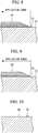
- the protruding portion 21 may be formed by coating application as illustrated in Fig. 10 .
- the process can be promptly shifted to the application of the abradable layer 20.
- the same material as the abradable material may be used as the coating material of the protruding portion 21. It accordingly becomes unnecessary to prepare a material different from that used in the formation of the abradable layer 20, and compatibility in the abradable layer 20 becomes higher. This can prevent detachment and the like.
- a vertical cross-sectional shape may be a semicircular shape, or a vertical cross-sectional shape may have a gently-inclined surface as in a protruding portion 25 illustrated in Fig. 11 .
- processing may be performed so as to roughen a roughness degree in an outside region 10B of a region 10A in which the abradable layer 20 is to be formed, to be rougher than a roughness degree in the region 10A in which the abradable layer 20 is to be formed.
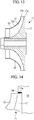
- an abradable layer 22 is formed in a side edge portion 12a of a blade 12 of an impeller 11 of a compressor 3.
- the abradable layer 22 is formed in the side edge portion 12a of the blade 12, which is a portion facing the inner peripheral surface of a housing 10 of the compressor 3.
- the abradable layer 22 is made of an abradable material similar to that in the first embodiment, and is formed so as to narrow a clearance gap between the housing 10 and the blade 12 of the impeller 11.
- the formation of the abradable layer 22 narrows the clearance gap between the housing 10 and the impeller 11.
- the abradable layer 22 is formed by applying coating of the abradable material only to a predetermined range at a tip of the blade 12. When the coating of the abradable material is solidified, the abradable layer 22 is formed in the predetermined range. In addition, because this is coating application, a coating thickness can be adjusted in the application, so that post-processing or finishing for adjusting a coating thickness is not performed.
- a method of applying coating of the abradable material similarly to the first embodiment, there are a method of using a constant amount discharge nozzle or a brush of which the position is controlled by a three-axis robot 30 in three-axis directions, and a method of using pad printing.
- a method of applying the abradable material is not limited to the coating application, and the abradable material may be applied by spray coating. Nevertheless, in this case, masking is performed on the outside of the predetermined range so that the abradable material is applied to the predetermined range.
- An area in which the abradable material is applied to the side edge portion 12a of the blade 12 of the impeller 11 is smaller than an area in which the abradable material is applied to the inner peripheral surface of the housing 10.
- the abradable layer 24 is formed on a surface, which is the inner peripheral surface of the housing 10 of the compressor 3, and is a surface facing the outer peripheral surface 17a of the end plate 17 of the impeller 11.
- the abradable layer 24 is made of an abradable material similar to that in the first embodiment, and is formed so as to narrow a clearance gap between the housing 10 and the end plate 17 of the impeller 11.
- the formation of the abradable layer 24 narrows the clearance gap between the housing 10 and the end plate 17 of the impeller 11.
- the abradable layer 24 is formed by applying coating of the abradable material only to a predetermined range on the surface facing the outer peripheral surface 17a of the end plate 17 of the impeller 11, in the inner peripheral surface of the housing 10. When the coating of the abradable material is solidified, the abradable layer 24 is formed in the predetermined range. In addition, because this is coating application, a coating thickness can be adjusted in the application, so that post-processing or finishing for adjusting a coating thickness is not performed.
- a method of applying the coating of the abradable material similarly to the first embodiment, there are a method of using a constant amount discharge nozzle or a brush of which the position is controlled by a three-axis robot 30 in three-axis directions, and a method of using pad printing.
- a method of applying the abradable material is not limited to the coating application, and the abradable material may be applied by spray coating. Nevertheless, in this case, masking is performed on the outside of the predetermined range so that the abradable material is applied to the predetermined range.
- An area in which the abradable material is applied to the surface facing the outer peripheral surface 17a of the end plate 17 of the impeller 11, in the inner peripheral surface of the housing 10 is smaller than an area in which the abradable material is applied to the surface facing the blade 12, in the inner peripheral surface of the housing 10.
- the present invention is not limited to this example. More specifically, when the impeller 11 and a bearing housing 15 face each other, an abradable layer may be formed on a surface facing the outer peripheral surface 17a of the end plate 17 of the impeller 11, not in the inner peripheral surface of the housing 10 but in the inner peripheral surface of the bearing housing 15.
- an abradable layer may be formed not on the inner peripheral surface side of the housing 10 or the bearing housing 15, but on the outer peripheral surface 17a of the end plate 17 of the impeller 11.
Landscapes
- Engineering & Computer Science (AREA)
- Chemical & Material Sciences (AREA)
- Mechanical Engineering (AREA)
- General Engineering & Computer Science (AREA)
- Materials Engineering (AREA)
- Chemical Kinetics & Catalysis (AREA)
- Metallurgy (AREA)
- Organic Chemistry (AREA)
- Physics & Mathematics (AREA)
- Plasma & Fusion (AREA)
- Sustainable Development (AREA)
- Life Sciences & Earth Sciences (AREA)
- Structures Of Non-Positive Displacement Pumps (AREA)
- Supercharger (AREA)
- Application Of Or Painting With Fluid Materials (AREA)
Abstract
Description
- The present invention relates to a method of manufacturing a supercharger including a compressor having an impeller configured to rotate according to the rotational force of a turbine to compress air.
- In a turbocharger (supercharger), a turbine rotationally drives according to exhaust gas of an engine, and an impeller of a centrifugal compressor rotates according to the rotational force of the turbine. Compressed air compressed by the centrifugal compressor is fed into the engine.
- In the centrifugal compressor of the turbocharger, on an inner surface side of a housing, a clearance gap is provided between the housing and the impeller. This can prevent contact between the housing and the impeller that is caused by the influence of heat expansion and vibration in operations, and component tolerance.
- On the other hand, by narrowing the clearance gap between the housing and the impeller, the performance of the turbocharger can be enhanced. For this reason, a member that is easily abraded even if the impeller comes into contact with the member (hereinafter, also referred to as an "abradable material".) is provided on a housing inner surface in some cases. The following PTL 1 discloses that an abradable coating layer made of synthetic resin is formed on an inner periphery of a housing that faces an impeller.
- An abradable layer narrows a clearance gap between the housing and the impeller. The performance can be thereby enhanced while reliability is assured because the impeller is not damaged even if the impeller comes into contact with the abradable layer.
-
- {PTL 1}
Japanese Unexamined Utility Model Application, Publication No.Hei 3-52398 - {PTL 2}
The Publication of Japanese Patent No.3639846 - {PTL 3}
Japanese Unexamined Patent Application, Publication No.2010-796 - The
aforementioned PTL 2 discloses a method of attaching a synthetic-resin slide member to a housing by adhesion. Nevertheless, productivity degrades because a process of manufacturing the synthetic-resin slide member and an adhesion process are additionally required, and the number of components increases. In addition, it is necessary to separately manufacture the synthetic-resin slide members according to the shape of the housing or the impeller, so that the number of types of components also increases. - The
aforementioned PTL 3 discloses a method of closely adhering a molding die to the inner surface side of a housing, and injecting synthetic resin into a space between the housing and the molding die. Using this method, a slide member is formed on the inner surface side of the housing through injection molding. Nevertheless, productivity is bad because it is necessary to change the molding die according to the shape of the housing or an impeller. - Furthermore, the aforementioned PTL 1 discloses a method of forming the abradable coating layer on the inner periphery of the housing by spraying synthetic resin onto the inner periphery of the housing by means of thermal spraying. Nevertheless, in the case of thermal spraying and spray coating, it is difficult to confine an application region. In addition, it is also difficult to adjust a coating thickness. Thus, masking of regions surrounding the application region, and post-processing or finishing for adjusting a coating thickness are generally required, which degrades productivity.
- The present invention has been contrived in view of such circumstances, and the object of the present invention is to provide a method of manufacturing a supercharger that can promptly and easily form an abradable layer in the supercharger.
- For solving the aforementioned problems, a method of manufacturing a supercharger according to the present invention employs the following solutions.
- More specifically, a method of manufacturing a supercharger according to the present invention is a method of manufacturing a supercharger including a turbine configured to rotationally drive, and a compressor having an impeller configured to rotate according to rotational force of the turbine and a housing configured to store the impeller, and the method includes a process of applying coating of an abradable material which is to form an abradable layer when being solidified, only to a predetermined range on either one of surfaces of the impeller and the housing via which the impeller and the housing face.
- With this configuration, because the coating of the abradable material is applied onto the surface of the impeller or the surface of the housing, it is unnecessary to additionally manufacture an abradable material as a component, and to perform changeover according to the shape of the impeller or the housing. In addition, in the coating application, adjustment of a coating thickness is generally easy, so that the post-processing and the finishing become unnecessary.
- For example, the coating of the abradable material is applied onto an inner peripheral surface of the housing (a surface facing a tip portion of a blade of the impeller, or a surface facing an outer peripheral surface on an end plate side of the impeller), the tip portion of the blade of the impeller, or the outer peripheral surface on the end plate side of the impeller.
- In the aforementioned invention, coating of the abradable material is applied only to the predetermined range without applying masking.
- With this configuration, because the coating of the abradable material is applied only to the predetermined range without applying masking, productivity can be enhanced. In addition, because the coating is applied without performing masking, the abradable material wetly spreads on the surface of the impeller or the housing. This consequently causes a state in which no level difference is generated at an end portion of the abradable layer, unlike a case of applying masking. Thus, the separation of airflow on the surface of the impeller or the housing can be suppressed, and efficiency degradation of the supercharger can also be suppressed.
- In the aforementioned invention, coating of the abradable material is applied using a constant amount discharge nozzle, a brush, or a pad.
- With this configuration, the coating of the abradable material is applied in a state in which the abradable material is brought close to the surface of the impeller or the housing, or pressed against the surface of the impeller or the housing. It is therefore easy to form the abradable layer only in the predetermined range without applying masking.
- In the aforementioned invention, a process of forming a protruding portion or a recess portion on the surface of the impeller or the housing at a boundary of a region in which the abradable layer is to be formed, before the process of applying coating of the abradable material is further included.
- With this configuration, by the protruding portion or the recess portion being formed on the surface of the impeller or the housing, it becomes difficult for the abradable material to spread excessively, and the abradable layer is surely applied to the predetermined range. When the protruding portion or the recess portion is formed, the protruding portion or the recess portion desirably has such a height or a depth that a flow of air is not disturbed, and preferably has such a shape that the abradable layer and the impeller or the housing are smoothly connected.
- In the aforementioned invention, a process of increasing a roughness degree in an outside region of a region in which the abradable layer is to be formed, to be rougher than a roughness degree in the region in which the abradable layer is to be formed, before the process of applying coating of the abradable material is further included.
- With this configuration, by the roughness degree getting higher in the outside region of the region in which the abradable layer is to be formed, it becomes difficult for the abradable material to spread excessively, and the abradable layer is surely applied to the predetermined range.
- In the aforementioned invention, the abradable material contains synthetic resin and fine particles having a self-lubricating property.
- With this configuration, because the slidability of the abradable layer is assured, frictional resistance caused when the impeller comes into contact therewith can be reduced, and damages to the impeller can be prevented.
- In the aforementioned invention, coating of the abradable material is applied so that a density becomes lower on a surface side of the abradable layer than a density on a side of the impeller or a side of the housing, when the abradable material is solidified.
- With this configuration, because strength becomes lower on the surface side of the abradable layer, the abradable material becomes easily-abradable when the impeller comes into contact therewith, and damages to the impeller can be prevented.
- According to the present invention, an abradable layer can be promptly and easily formed in a supercharger.
-
- {
Fig. 1 }
Fig. 1 is a vertical cross-sectional view illustrating a supercharger according to a first embodiment of the present invention. - {
Fig. 2 }
Fig. 2 is a vertical cross-sectional view illustrating a housing of a compressor of the supercharger according to the first embodiment of the present invention. - {
Fig. 3 }
Fig. 3 is a vertical cross-sectional view illustrating an abradable layer formed on a housing inner surface of the supercharger according to the first embodiment of the present invention, and illustrates a state immediately after coating application. - {
Fig. 4 }
Fig. 4 is a vertical cross-sectional view illustrating the abradable layer formed on the housing inner surface of the supercharger according to the first embodiment of the present invention, and illustrates a state in which time has elapsed from the coating application. - {
Fig. 5 }
Fig. 5 is a perspective view illustrating a three-axis robot and a constant amount discharge nozzle. - {
Fig. 6 }
Fig. 6 is a schematic view illustrating a pad and a container in pad printing. - {
Fig. 7 }
Fig. 7 is a schematic view illustrating the housing of the supercharger and the pad in the pad printing. - {
Fig. 8 }
Fig. 8 is a vertical cross-sectional view illustrating the abradable layer and a protruding portion according to the first embodiment of the present invention. - {
Fig. 9 }
Fig. 9 is a vertical cross-sectional view illustrating the abradable layer and a recess portion according to the first embodiment of the present invention. - {
Fig. 10 }
Fig. 10 is a vertical cross-sectional view illustrating a protruding portion according to the first embodiment of the present invention. - {
Fig. 11 }
Fig. 11 is a vertical cross-sectional view illustrating the abradable layer and a protruding portion according to the first embodiment of the present invention. - {
Fig. 12 }
Fig. 12 is a vertical cross-sectional view illustrating the abradable layer according to the first embodiment of the present invention. - {
Fig. 13 }
Fig. 13 is a vertical cross-sectional view illustrating an impeller of a supercharger according to a second embodiment of the present invention. - {
Fig. 14 }
Fig. 14 is a partially-enlarged vertical cross-sectional view illustrating an impeller and a housing of a supercharger according to a third embodiment of the present invention. - {
Fig. 15 }
Fig. 15 is a vertical cross-sectional view illustrating an abradable layer formed on a housing inner surface of a conventional supercharger, and illustrates a state in which a masking tape is peeled off. - A turbocharger (supercharger) according to a first embodiment of the present invention will be described below using
Fig. 1 . - A turbocharger 1 includes a
turbine 2, acompressor 3, and arotation shaft 4 coupled to theturbine 2 and thecompressor 3. Theturbine 2 rotationally drives according to exhaust gas from an engine, and animpeller 11 of thecompressor 3 rotates according to the rotational force of theturbine 2. Air compressed by thecompressor 3 is supplied to the engine. - The
turbine 2 is disposed on one end side of therotation shaft 4, and includes animpeller 6, ahousing 5, and the like. - The
impeller 6 includes ablade 7, and is coupled to therotation shaft 4 to rotate around a shaft line. - The
housing 5 covers theimpeller 6 from the outside, and ascroll passage 8 communicating the inside and the outside of thehousing 5 is formed therein. Thescroll passage 8 extends from an end portion (aleading edge portion 7a) on the outside in a radial direction of theblade 7, outward in the radial direction, and is formed into a ring shape around the shaft line of therotation shaft 4. The exhaust gas is introduced into theimpeller 6 from thescroll passage 8 to rotate theimpeller 6 and therotation shaft 4. - A
discharge port 9 opening on one end side of the shaft line of therotation shaft 4 is formed in thehousing 5. Exhaust gas having passed through theblade 7 is discharged to the outside of thehousing 5 through thedischarge port 9. - The
compressor 3 is a centrifugal compressor, for example, and is disposed on the other end side of therotation shaft 4, and includes theimpeller 11, ahousing 10, and the like. - The
impeller 11 includes ablade 12, and is coupled to therotation shaft 4 to rotate around the shaft line. - The
housing 10 covers theimpeller 11 from the outside. Asuction port 13 opening on the other end side of the shaft line of therotation shaft 4 is formed in thehousing 10. Air is introduced into theimpeller 11 from the outside through thesuction port 13. The rotational force of theimpeller 6 of theturbine 2 is transmitted to theimpeller 11 via therotation shaft 4, so that theimpeller 11 rotates. Air introduced from the outside is compressed by passing through theimpeller 11. - A
compressor passage 14 communicating the inside and the outside of thehousing 10 is formed in thehousing 10, and thecompressor passage 14 extends from an end portion (a trailingedge portion 12b) on the outside in a radial direction of theblade 12, outward in the radial direction, and is formed into a ring shape around the shaft line of therotation shaft 4. Air compressed in theimpeller 11 is introduced into thecompressor passage 14 and is discharged to the outside of thehousing 10. - A bearing
housing 15 is disposed between theturbine 2 and thecompressor 3 to couple theturbine 2 and thecompressor 3. The bearinghousing 15 covers therotation shaft 4 from the outside. Abearing 16 is provided in the bearinghousing 15, and thebearing 16 supports therotation shaft 4 so as to be rotatable with respect to the bearinghousing 15. - In addition, depending on the configuration of the turbocharger 1, in some cases, the bearing
housing 15 is disposed so that an inner peripheral surface of the bearinghousing 15 faces theimpeller 11. - An abradable layer 20 (refer to
Fig. 2 ) is formed in a portion on the inner peripheral surface of thehousing 10 of thecompressor 3 that faces aside edge portion 12a of theblade 12. Theabradable layer 20 is made of a material that is easily abraded even if theimpeller 11 comes into contact with the material (hereinafter, referred to as an "abradable material".), and is formed so as to narrow a clearance gap between thehousing 10 and theblade 12 of theimpeller 11. The formation of theabradable layer 20 narrows the clearance gap between thehousing 10 and theimpeller 11. As a result, the performance of the turbocharger 1 can be enhanced, and reliability can be assured because theimpeller 11 is not damaged even if theimpeller 11 comes into contact with theabradable layer 20. - The abradable material is a material which is to form the
abradable layer 20 when being solidified, and is synthetic resin, for example. Epoxy resin, polyamide, polyimide, and the like can be applied as synthetic resin. In addition, as the abradable material, synthetic resin may contain fine particles having a self-lubricating property that are dispersed at a content rate of 5 wt% to 50 wt%. The fine particles have a grain size of 5 µm to 50 µm, and examples of the fine particles include molybdenum disulfide, polytetrafluoroethylene (PTFE), hexagonal boron nitride (hBN), graphite, and the like. - By the fine particles having a self-lubricating property being dispersed in the abradable material, the slidability of the solidified
abradable layer 20 can be assured. As a result, frictional resistance caused when theimpeller 11 comes into contact with theabradable layer 20 can be reduced, and damages to theimpeller 11 can be prevented. - In addition, the
abradable layer 20 may have such a structure that a resin density becomes lower on a surface side of theabradable layer 20 than that on a surface adhering to thehousing 10 being a base material. With this structure, theabradable layer 20 tightly adheres to thehousing 10 on the surface adhering to thehousing 10, whereas the strength of theabradable layer 20 becomes lower on the surface side of theabradable layer 20. Thus, theabradable layer 20 becomes easily-abradable when theimpeller 11 comes into contact with theabradable layer 20, and damages to theimpeller 11 can be prevented. - As a method of lowering the resin density on the surface side of the
abradable layer 20, the following methods are conceivable. - (1) No air bubble is contained on the surface side adhering to the
housing 10, whereas air bubbles are contained on the surface side of theabradable layer 20. A layer containing air bubbles is thereby formed on the surface side of theabradable layer 20, and the resin density on the surface side of theabradable layer 20 can be lowered. - (2) An asperity surface having a relatively-high surface roughness degree is formed on the surface of the
abradable layer 20. Similarly to the case of (1), the resin density on the surface side of theabradable layer 20 can be thereby lowered. - (3) A content rate of fine particles on the surface side of the
abradable layer 20 is made higher than that on the surface side adhering to thehousing 10. Accordingly, a larger number of fine particles are contained on the surface side of theabradable layer 20, and the resin density on the surface side of theabradable layer 20 can be lowered. More specifically, by dispersing, in the abradable material, fine particles with a density lower than that of synthetic resin serving as a base material, the fine particles are suspended on the surface side before the abradable material is solidified, and then, the fine particles are fixed on the surface side when the abradable material is solidified. Examples of the fine particles include molybdenum disulfide, PTFE, hBN, graphite, hollow floating fine particles, and the like. - For lowering the resin density on the surface side of the
abradable layer 20, the aforementioned (1) to (3) methods may be implemented using the same synthetic resin, or may be implemented as a multilayered structure including two or more layers using different types of synthetic resin or different compositions. For example, synthetic resin or a composition having high density and high adhesiveness is employed on the surface side adhering to thehousing 10, whereas synthetic resin or a composition having high abradability is employed on the surface side of theabradable layer 20. - A method of applying the
abradable layer 20 according to the present embodiment will be described below. - The
abradable layer 20 is formed by applying coating of the abradable material only to a predetermined range on the inner peripheral surface of thehousing 10, without applying masking. In addition, because this is coating application, a coating thickness can be adjusted in the application, so that post-processing or finishing for adjusting a coating thickness is not performed. - Because the coating of the abradable material is applied onto the surface of the
housing 10, it is unnecessary to additionally manufacture an abradable material as a component, and to perform changeover according to the shape of theimpeller 11 or thehousing 10. In addition, because the coating application can be performed in the same productive facilities regardless of the shape of theimpeller 11 or thehousing 10, productivity is high. - In addition, unlike conventional thermal spraying and spray coating, the coating application can form the
abradable layer 20 only in the predetermined range without applying masking. This can enhance productivity. Furthermore, in the coating application, adjustment of a coating thickness can be easily performed, so that the post-processing and the finishing become unnecessary. As a result, mass productivity becomes high, and the application can be performed inexpensively. - Furthermore, because the coating is applied without performing masking, the
abradable layer 20 obtained immediately after the coating application is in a state as illustrated inFig. 3 , and the abradable material wetly spreads on the surface of thehousing 10 as time elapses. When masking is applied, after the abradable material is solidified to some extent, a maskingtape 38 or the like is peeled off as illustrated inFig. 15 . This generates a level difference at an end portion of anabradable layer 26. In contrast, unlike the case of applying masking, the present embodiment can cause a state in which no level difference is generated at an end portion of theabradable layer 20 as illustrated inFig. 4 . Thus, the separation of airflow on the surface of thehousing 10 can be suppressed, and efficiency degradation of the supercharger can also be suppressed. - As a method of applying coating of the abradable material, as illustrated in
Fig. 5 , there is a method of using a constantamount discharge nozzle 32 of which the position is controlled by a three-axis robot 30 in three-axis directions. In addition, thehousing 10 to which the abradable material is applied is not illustrated inFig. 5 . The constantamount discharge nozzle 32 is provided in the three-axis robot 30, and the constantamount discharge nozzle 32 is supplied with the abradable material from atank 34. An amount of the abradable material discharged from the constantamount discharge nozzle 32 is adjusted by adjusting the pressure of air supplied from a controller 36. - With this configuration, the coating of the abradable material is applied in a state in which the abradable material is brought close to the surface of the
housing 10. Thus, theabradable layer 20 can be formed only in the predetermined range without applying masking. In addition, a device that performs the position control of the constantamount discharge nozzle 32 is not limited to the three-axis robot 30, and another device such as a robot that can perform position control only in two-axis directions may be used. - In addition, a tool used in the coating application performed on the surface of the
housing 10 is not limited to the constant amount discharge nozzle, and a brush may be used. Also in this case, position control is performed by the three-axis robot 30 or the like. The brush is installed in place of the aforementioned constantamount discharge nozzle 32. With this configuration, the coating of the abradable material is applied in a state in which the abradable material is pressed against the surface of thehousing 10. Thus, theabradable layer 20 can be formed only in the predetermined range without applying masking. - Furthermore, as illustrated in
Figs. 6 and 7 , the coating application performed on the surface of thehousing 10 may be performed by pad printing. A generally-performed method can be applied to the pad printing. More specifically, after anabradable material 44 stored in acontainer 42 is adhered to asilicone pad 40 as illustrated inFig. 6 , thepad 40 is brought into contact with thehousing 10 as illustrated inFig. 7 . The coating of theabradable material 44 is thereby applied onto the inner surface of thehousing 10. Also in this case, the coating of the abradable material is applied in a state in which the abradable material is pressed against the surface of thehousing 10. Thus, theabradable layer 20 can be formed only in the predetermined range without applying masking. - Before the coating of the abradable material is applied onto the surface of the
housing 10, as illustrated inFig. 8 or 9 , a protrusion (protruding portion 21) or a recess (recess portion 23) may be formed on the surface of thehousing 10 at a boundary of a region in which theabradable layer 20 is to be formed. By the protrudingportion 21 or therecess portion 23 being formed on the surface of thehousing 10, it becomes difficult for the abradable material to spread excessively, so that theabradable layer 20 is surely applied to the predetermined range. The protrudingportion 21 or therecess portion 23 has such a height or a depth that a flow of air is not disturbed, and the performance of the turbocharger 1 is not affected. It is desirable that the protrudingportion 21 be a minute protrusion lower than the height of theabradable layer 20. - Various methods can be applied to the formation of the protruding
portion 21. For example, the protrudingportion 21 may be formed by coating application as illustrated inFig. 10 . In this process, by using a quick-drying material as a coating material of the protrudingportion 21, the process can be promptly shifted to the application of theabradable layer 20. In addition, the same material as the abradable material may be used as the coating material of the protrudingportion 21. It accordingly becomes unnecessary to prepare a material different from that used in the formation of theabradable layer 20, and compatibility in theabradable layer 20 becomes higher. This can prevent detachment and the like. - As the shape of the protruding
portion 21, a vertical cross-sectional shape may be a semicircular shape, or a vertical cross-sectional shape may have a gently-inclined surface as in a protrudingportion 25 illustrated inFig. 11 . By forming the shape of the protrudingportion 25 into a shape smoothly connected to the surface of thehousing 10 on an upstream side of a flow of air on theabradable layer 20, the protrudingportion 25 can be prevented from disturbing the flow of air. - In addition, as illustrated in
Fig. 12 , before the coating of the abradable material is applied onto the surface of thehousing 10, processing may be performed so as to roughen a roughness degree in anoutside region 10B of aregion 10A in which theabradable layer 20 is to be formed, to be rougher than a roughness degree in theregion 10A in which theabradable layer 20 is to be formed. With this configuration, by the roughness degree getting higher in theoutside region 10B of theregion 10A in which theabradable layer 20 is to be formed, it becomes difficult for the abradable material to spread excessively, so that theabradable layer 20 is surely applied to the predetermined range. - Next, a turbocharger according to a second embodiment of the present invention will be described. In the aforementioned first embodiment, the description has been given of a case in which the
abradable layer 20 is formed in the predetermined range on the inner peripheral surface of thehousing 10 of thecompressor 3. Nevertheless, the present invention is not limited to this example. In the present embodiment, as illustrated inFig. 13 , anabradable layer 22 is formed in aside edge portion 12a of ablade 12 of animpeller 11 of acompressor 3. - In the following description, the detailed descriptions of components described in the first embodiment will be omitted.
- In the present embodiment, the
abradable layer 22 is formed in theside edge portion 12a of theblade 12, which is a portion facing the inner peripheral surface of ahousing 10 of thecompressor 3. - The
abradable layer 22 is made of an abradable material similar to that in the first embodiment, and is formed so as to narrow a clearance gap between thehousing 10 and theblade 12 of theimpeller 11. The formation of theabradable layer 22 narrows the clearance gap between thehousing 10 and theimpeller 11. As a result, the performance of a turbocharger 1 can be enhanced, and reliability can be assured because theimpeller 11 is not damaged even if theimpeller 11 comes into contact with theabradable layer 22. - The
abradable layer 22 is formed by applying coating of the abradable material only to a predetermined range at a tip of theblade 12. When the coating of the abradable material is solidified, theabradable layer 22 is formed in the predetermined range. In addition, because this is coating application, a coating thickness can be adjusted in the application, so that post-processing or finishing for adjusting a coating thickness is not performed. - As a method of applying coating of the abradable material, similarly to the first embodiment, there are a method of using a constant amount discharge nozzle or a brush of which the position is controlled by a three-
axis robot 30 in three-axis directions, and a method of using pad printing. In addition, a method of applying the abradable material is not limited to the coating application, and the abradable material may be applied by spray coating. Nevertheless, in this case, masking is performed on the outside of the predetermined range so that the abradable material is applied to the predetermined range. - An area in which the abradable material is applied to the
side edge portion 12a of theblade 12 of theimpeller 11 is smaller than an area in which the abradable material is applied to the inner peripheral surface of thehousing 10. Thus, by applying the abradable material not to thehousing 10 but to theimpeller 11, a used amount of the abradable material can be reduced to a small amount, and the application of the abradable material becomes inexpensive. In addition, a volume of theimpeller 11 is smaller than that of thehousing 10. Thus, when synthetic resin of the abradable material is thermoset resin, and rises in temperature when being cured, a temperature rise speed of theimpeller 11 becomes higher than that of thehousing 10. This can shorten an application time, and can reduce facility costs. - Next, a turbocharger according to a third embodiment of the present invention will be described. In the aforementioned first embodiment, the description has been given of a case in which the
abradable layer 20 is formed on a surface facing theblade 12, in the inner peripheral surface of thehousing 10 of thecompressor 3. Nevertheless, the present invention is not limited to this example. In the present embodiment, as illustrated inFig. 14 , anabradable layer 24 is formed on a surface facing an outerperipheral surface 17a of anend plate 17 of animpeller 11, in the inner peripheral surface of ahousing 10 of acompressor 3. - In the following description, the detailed descriptions of components described in the first embodiment will be omitted.
- In the present embodiment, the
abradable layer 24 is formed on a surface, which is the inner peripheral surface of thehousing 10 of thecompressor 3, and is a surface facing the outerperipheral surface 17a of theend plate 17 of theimpeller 11. - The
abradable layer 24 is made of an abradable material similar to that in the first embodiment, and is formed so as to narrow a clearance gap between thehousing 10 and theend plate 17 of theimpeller 11. The formation of theabradable layer 24 narrows the clearance gap between thehousing 10 and theend plate 17 of theimpeller 11. As a result, the performance of a turbocharger 1 can be enhanced, and reliability can be assured because theimpeller 11 is not damaged even if theimpeller 11 comes into contact with theabradable layer 24. - The
abradable layer 24 is formed by applying coating of the abradable material only to a predetermined range on the surface facing the outerperipheral surface 17a of theend plate 17 of theimpeller 11, in the inner peripheral surface of thehousing 10. When the coating of the abradable material is solidified, theabradable layer 24 is formed in the predetermined range. In addition, because this is coating application, a coating thickness can be adjusted in the application, so that post-processing or finishing for adjusting a coating thickness is not performed. - As a method of applying the coating of the abradable material, similarly to the first embodiment, there are a method of using a constant amount discharge nozzle or a brush of which the position is controlled by a three-
axis robot 30 in three-axis directions, and a method of using pad printing. In addition, a method of applying the abradable material is not limited to the coating application, and the abradable material may be applied by spray coating. Nevertheless, in this case, masking is performed on the outside of the predetermined range so that the abradable material is applied to the predetermined range. - An area in which the abradable material is applied to the surface facing the outer
peripheral surface 17a of theend plate 17 of theimpeller 11, in the inner peripheral surface of thehousing 10 is smaller than an area in which the abradable material is applied to the surface facing theblade 12, in the inner peripheral surface of thehousing 10. Thus, by applying the abradable material to the surface facing the outerperipheral surface 17a of theend plate 17 of theimpeller 11, a used amount of the abradable material can be reduced to a small amount, and the application of the abradable material becomes inexpensive. - In addition, in the aforementioned embodiment, the description has been given of a case in which the abradable material is applied to the surface facing the outer
peripheral surface 17a of theend plate 17 of theimpeller 11, in the inner peripheral surface of thehousing 10. Nevertheless, the present invention is not limited to this example. More specifically, when theimpeller 11 and a bearinghousing 15 face each other, an abradable layer may be formed on a surface facing the outerperipheral surface 17a of theend plate 17 of theimpeller 11, not in the inner peripheral surface of thehousing 10 but in the inner peripheral surface of the bearinghousing 15. - In addition, an abradable layer may be formed not on the inner peripheral surface side of the
housing 10 or the bearinghousing 15, but on the outerperipheral surface 17a of theend plate 17 of theimpeller 11. - Also in these cases, a clearance gap between the
housing 10 and theend plate 17 of theimpeller 11 becomes narrower. As a result, the performance of the turbocharger 1 can be enhanced, and reliability can be assured because theimpeller 11 is not damaged even if theimpeller 11 comes into contact with the abradable layer. -
- 1 turbocharger
- 2 turbine
- 3 compressor
- 4 rotation shaft
- 5 housing
- 6 impeller
- 7 blade
- 8 scroll passage
- 9 discharge port
- 10 housing
- 11 impeller
- 12 blade
- 13 suction port
- 14 compressor passage
- 15 bearing housing (housing)
- 16 bearing
- 17 end plate
- 20, 22, 24 abradable layer
Claims (7)
- A method of manufacturing a supercharger including a turbine configured to rotationally drive, and a compressor having an impeller configured to rotate according to rotational force of the turbine and a housing configured to store the impeller, the method comprising:a process of applying coating of an abradable material which is to form an abradable layer when being solidified, only to a predetermined range on either one of surfaces of the impeller and the housing via which the impeller and the housing face.
- The method of manufacturing a supercharger according to claim 1, wherein coating of the abradable material is applied only to the predetermined range without applying masking.
- The method of manufacturing a supercharger according to claim 1 or 2, wherein coating of the abradable material is applied using a constant amount discharge nozzle, a brush, or a pad.
- The method of manufacturing a supercharger according to any one of claims 1 to 3, further comprising a process of forming a protruding portion or a recess portion on the surface of the impeller or the housing at a boundary of a region in which the abradable layer is to be formed, before the process of applying coating of the abradable material.
- The method of manufacturing a supercharger according to any one of claims 1 to 3, further comprising a process of increasing a roughness degree in an outside region of a region in which the abradable layer is to be formed, to be rougher than a roughness degree in the region in which the abradable layer is to be formed, before the process of applying coating of the abradable material.
- The method of manufacturing a supercharger according to any one of claims 1 to 5, wherein the abradable material contains synthetic resin and fine particles having a self-lubricating property.
- The method of manufacturing a supercharger according to any one of claims 1 to 6, wherein coating of the abradable material is applied so that a density becomes lower on a surface side of the abradable layer than a density on a side of the impeller or a side of the housing, when the abradable material is solidified.
Applications Claiming Priority (1)
| Application Number | Priority Date | Filing Date | Title |
|---|---|---|---|
| PCT/JP2015/055960 WO2016135973A1 (en) | 2015-02-27 | 2015-02-27 | Method of manufacturing turbocharger |
Publications (3)
| Publication Number | Publication Date |
|---|---|
| EP3263909A1 true EP3263909A1 (en) | 2018-01-03 |
| EP3263909A4 EP3263909A4 (en) | 2018-12-05 |
| EP3263909B1 EP3263909B1 (en) | 2020-08-19 |
Family
ID=56788252
Family Applications (1)
| Application Number | Title | Priority Date | Filing Date |
|---|---|---|---|
| EP15883267.5A Active EP3263909B1 (en) | 2015-02-27 | 2015-02-27 | Method of manufacturing turbocharger |
Country Status (5)
| Country | Link |
|---|---|
| US (1) | US11028855B2 (en) |
| EP (1) | EP3263909B1 (en) |
| JP (1) | JP6607580B2 (en) |
| CN (1) | CN107250552B (en) |
| WO (1) | WO2016135973A1 (en) |
Cited By (1)
| Publication number | Priority date | Publication date | Assignee | Title |
|---|---|---|---|---|
| WO2019157118A1 (en) * | 2018-02-09 | 2019-08-15 | Borgwarner Inc. | Impeller wheel for a turbocharger and method of making the same |
Families Citing this family (4)
| Publication number | Priority date | Publication date | Assignee | Title |
|---|---|---|---|---|
| CN107327318B (en) * | 2017-07-25 | 2023-09-22 | 湖南天雁机械有限责任公司 | Turbocharger with tip clearance control using abradable coating |
| US11478981B2 (en) * | 2017-12-06 | 2022-10-25 | Safran Aircraft Engines | Method for manufacturing an ordered network of acoustic channels made of abradable material |
| US11554534B2 (en) * | 2017-12-06 | 2023-01-17 | Safran Aircraft Engines | Method for in situ additive manufacturing of a coating on a turbomachine casing |
| US11441570B2 (en) * | 2019-06-12 | 2022-09-13 | Lg Electronics Inc. | Motor assembly and method for manufacturing the same |
Family Cites Families (53)
| Publication number | Priority date | Publication date | Assignee | Title |
|---|---|---|---|---|
| US3046648A (en) * | 1959-04-13 | 1962-07-31 | Aircraft Prec Products Inc | Method of manufacturing replaceable labyrinth type seal assembly |
| US4349313A (en) * | 1979-12-26 | 1982-09-14 | United Technologies Corporation | Abradable rub strip |
| US4450184A (en) * | 1982-02-16 | 1984-05-22 | Metco Incorporated | Hollow sphere ceramic particles for abradable coatings |
| JPH0396601A (en) * | 1989-09-08 | 1991-04-22 | Toyota Motor Corp | Relative moving device |
| US5185217A (en) | 1989-09-08 | 1993-02-09 | Toyota Jidosha Kabushiki Kaisha | Relatively displacing apparatus |
| JPH03156103A (en) * | 1989-11-10 | 1991-07-04 | Toyota Motor Corp | Relative displacement device |
| JPH0352398U (en) | 1989-09-29 | 1991-05-21 | ||
| JPH0368529U (en) * | 1989-11-06 | 1991-07-05 | ||
| JPH03237299A (en) * | 1990-02-09 | 1991-10-23 | Toyota Motor Corp | Manufacture of clearance adjusting film layer |
| US5435872A (en) * | 1991-11-01 | 1995-07-25 | Decc Technology Partnership | Sized coated pistons |
| GB9520497D0 (en) * | 1995-10-07 | 1995-12-13 | Holset Engineering Co | Improvements in turbines and compressors |
| WO1998048157A1 (en) | 1997-04-22 | 1998-10-29 | Kyoritsu Corp. | Turbo charger equipped with sliding member |
| JP2000345984A (en) * | 1999-06-02 | 2000-12-12 | Matsushita Electric Ind Co Ltd | Compressor |
| DE10121019A1 (en) * | 2001-04-28 | 2002-10-31 | Alstom Switzerland Ltd | Gas turbine seal |
| US6511422B1 (en) * | 2002-04-30 | 2003-01-28 | Karl Storz Imaging, Inc. | Method and apparatus for protection from high intensity light |
| JP4305928B2 (en) * | 2002-10-09 | 2009-07-29 | 株式会社Ihi | Rotating body and coating method thereof |
| CA2483528C (en) | 2002-10-09 | 2015-07-21 | Ishikawajima-Harima Heavy Industries Co., Ltd. | Rotating member and method for coating the same |
| US20050003172A1 (en) * | 2002-12-17 | 2005-01-06 | General Electric Company | 7FAstage 1 abradable coatings and method for making same |
| JP4868037B2 (en) | 2003-03-20 | 2012-02-01 | 株式会社Ihi | Supercharger manufacturing method and supercharger |
| DE102004056179A1 (en) * | 2004-11-20 | 2006-05-24 | Borgwarner Inc. Powertrain Technical Center, Auburn Hills | Method for producing a compressor housing |
| JP2006150155A (en) * | 2004-11-25 | 2006-06-15 | Seiko Epson Corp | Droplet discharge head, method for manufacturing droplet discharge head, and droplet discharge apparatus |
| US20070134411A1 (en) * | 2005-12-14 | 2007-06-14 | General Electric Company | Method for making compositions containing microcapsules and compositions made thereof |
| DE102006004769B4 (en) * | 2006-02-02 | 2022-05-25 | Mercedes-Benz Group AG | Surface conditioning for thermal spray coatings |
| PL2078060T3 (en) * | 2006-10-30 | 2017-09-29 | Andrew W. Suman | Abradable dry film lubricant and the method for applying same and article made therefrom |
| US8105012B2 (en) * | 2008-03-12 | 2012-01-31 | Opra Technologies B.V. | Adjustable compressor bleed system and method |
| DE102010048147B4 (en) * | 2010-10-11 | 2016-04-21 | MTU Aero Engines AG | Layer system for rotor / stator seal of a turbomachine and method for producing such a layer system |
| US20140199163A1 (en) | 2011-03-09 | 2014-07-17 | Rolls-Royce Corporation- | Abradable layer including a low thermal conductivity composition |
| GB201116029D0 (en) * | 2011-09-16 | 2011-10-26 | Rolls Royce Plc | Abradable panel and method of forming the same |
| US8685545B2 (en) * | 2012-02-13 | 2014-04-01 | Siemens Aktiengesellschaft | Thermal barrier coating system with porous tungsten bronze structured underlayer |
| US10215033B2 (en) * | 2012-04-18 | 2019-02-26 | General Electric Company | Stator seal for turbine rub avoidance |
| WO2014099814A1 (en) * | 2012-12-17 | 2014-06-26 | General Electric Company | Robust turbine blades |
| EP3068978B1 (en) * | 2013-11-13 | 2019-03-27 | United Technologies Corporation | Turbomachinery blade outer air seal |
| EP2886804B1 (en) * | 2013-12-20 | 2017-08-16 | Safran Aero Boosters SA | Sealing device for a compressor of a turbomachine |
| US10539036B2 (en) * | 2014-01-14 | 2020-01-21 | United Technologies Corporation | Abradable seal having nanolayer material |
| EP2896796B1 (en) * | 2014-01-20 | 2019-09-18 | Safran Aero Boosters SA | Stator of an axial turbomachine and corresponding turbomachine |
| US8939707B1 (en) * | 2014-02-25 | 2015-01-27 | Siemens Energy, Inc. | Turbine abradable layer with progressive wear zone terraced ridges |
| US8939706B1 (en) * | 2014-02-25 | 2015-01-27 | Siemens Energy, Inc. | Turbine abradable layer with progressive wear zone having a frangible or pixelated nib surface |
| EP3111055A2 (en) * | 2014-02-25 | 2017-01-04 | Siemens Aktiengesellschaft | Turbine component thermal barrier coating with depth-varying material properties |
| US10036402B2 (en) * | 2014-05-14 | 2018-07-31 | United Technologies Corporation | Max phase reinforced polymer matrix composite abradables with enhanced thermal conductivity |
| US9957826B2 (en) * | 2014-06-09 | 2018-05-01 | United Technologies Corporation | Stiffness controlled abradeable seal system with max phase materials and methods of making same |
| US20150354393A1 (en) * | 2014-06-10 | 2015-12-10 | General Electric Company | Methods of manufacturing a shroud abradable coating |
| US20150354392A1 (en) * | 2014-06-10 | 2015-12-10 | General Electric Company | Abradable coatings |
| US10132185B2 (en) * | 2014-11-07 | 2018-11-20 | Rolls-Royce Corporation | Additive process for an abradable blade track used in a gas turbine engine |
| BE1022513B1 (en) * | 2014-11-18 | 2016-05-19 | Techspace Aero S.A. | INTERNAL COMPRESSOR OF AXIAL TURBOMACHINE COMPRESSOR |
| JP6210459B2 (en) | 2014-11-25 | 2017-10-11 | 三菱重工業株式会社 | Impeller and rotating machine |
| US10533439B2 (en) * | 2014-12-16 | 2020-01-14 | United Technologies Corporation | Gas turbine engine component with abrasive surface formed by electrical discharge machining |
| DE102015202070A1 (en) * | 2015-02-05 | 2016-08-25 | MTU Aero Engines AG | Gas turbine component |
| US20170016454A1 (en) * | 2015-02-25 | 2017-01-19 | United Technologies Corporation | Method for coating compressor blade tips |
| JP2017082666A (en) * | 2015-10-27 | 2017-05-18 | 株式会社オティックス | Supercharger compressor housing and manufacturing method for the same |
| US10145252B2 (en) * | 2015-12-09 | 2018-12-04 | General Electric Company | Abradable compositions and methods for CMC shrouds |
| FR3044945B1 (en) * | 2015-12-14 | 2018-01-12 | Centre National De La Recherche Scientifique | ABRADABLE COATING WITH VARIABLE DENSITY |
| US20180087387A1 (en) * | 2016-09-28 | 2018-03-29 | General Electric Company | Compositions and methods for coating metal turbine blade tips |
| US10329938B2 (en) * | 2017-05-31 | 2019-06-25 | General Electric Company | Aspirating face seal starter tooth abradable pocket |
-
2015
- 2015-02-27 WO PCT/JP2015/055960 patent/WO2016135973A1/en not_active Ceased
- 2015-02-27 CN CN201580076962.8A patent/CN107250552B/en active Active
- 2015-02-27 JP JP2017501813A patent/JP6607580B2/en active Active
- 2015-02-27 EP EP15883267.5A patent/EP3263909B1/en active Active
- 2015-02-27 US US15/551,660 patent/US11028855B2/en active Active
Cited By (1)
| Publication number | Priority date | Publication date | Assignee | Title |
|---|---|---|---|---|
| WO2019157118A1 (en) * | 2018-02-09 | 2019-08-15 | Borgwarner Inc. | Impeller wheel for a turbocharger and method of making the same |
Also Published As
| Publication number | Publication date |
|---|---|
| JP6607580B2 (en) | 2019-11-20 |
| CN107250552A (en) | 2017-10-13 |
| JPWO2016135973A1 (en) | 2018-01-18 |
| WO2016135973A1 (en) | 2016-09-01 |
| US20180051707A1 (en) | 2018-02-22 |
| EP3263909B1 (en) | 2020-08-19 |
| CN107250552B (en) | 2020-02-14 |
| US11028855B2 (en) | 2021-06-08 |
| EP3263909A4 (en) | 2018-12-05 |
Similar Documents
| Publication | Publication Date | Title |
|---|---|---|
| US11028855B2 (en) | Method of manufacturing supercharger | |
| CN102753833B (en) | With machine and the method that can grind ridge | |
| EP2907975B1 (en) | Polymer-coated blade with abrasive tip | |
| EP3239465B1 (en) | Process for manufacturing an abrasive blade tip | |
| US10309233B2 (en) | Abrasive tip blade manufacture methods | |
| CN107250507A (en) | The manufacture method of impeller cover, rotating machinery and impeller cover | |
| EP3239464B1 (en) | Abrasive blade tip | |
| US9534503B2 (en) | Rotary machine | |
| US10422242B2 (en) | Abrasive blade tips with additive resistant to clogging by organic matrix abradable | |
| US20260049554A1 (en) | Blade with abrasive tip | |
| US20190186281A1 (en) | Compressor abradable seal with improved solid lubricant retention | |
| US10472983B2 (en) | On-off valve device and rotary machine | |
| US20170107993A1 (en) | Air cycle machine compressor housing | |
| EP2796687A1 (en) | Turbocharger | |
| CN101275583B (en) | Abradable and anti-encrustation coating for rotating fluid machines | |
| US20120087781A1 (en) | Layer system for rotor/stator seal of a turbomachine and method for producing this type of layer system | |
| JP6469811B2 (en) | Corrosion erosion prevention structure, pump including the same, pump manufacturing method and repair method | |
| US11821331B2 (en) | Steam turbine, and blade | |
| JPH06234961A (en) | Production of pressure-sensitive adhesive tape | |
| WO2025205518A1 (en) | Nozzle, nozzle unit, and coating device | |
| JPH0925886A (en) | Vacuum pump |
Legal Events
| Date | Code | Title | Description |
|---|---|---|---|
| STAA | Information on the status of an ep patent application or granted ep patent |
Free format text: STATUS: THE INTERNATIONAL PUBLICATION HAS BEEN MADE |
|
| PUAI | Public reference made under article 153(3) epc to a published international application that has entered the european phase |
Free format text: ORIGINAL CODE: 0009012 |
|
| STAA | Information on the status of an ep patent application or granted ep patent |
Free format text: STATUS: REQUEST FOR EXAMINATION WAS MADE |
|
| 17P | Request for examination filed |
Effective date: 20170822 |
|
| AK | Designated contracting states |
Kind code of ref document: A1 Designated state(s): AL AT BE BG CH CY CZ DE DK EE ES FI FR GB GR HR HU IE IS IT LI LT LU LV MC MK MT NL NO PL PT RO RS SE SI SK SM TR |
|
| AX | Request for extension of the european patent |
Extension state: BA ME |
|
| DAX | Request for extension of the european patent (deleted) | ||
| RAP1 | Party data changed (applicant data changed or rights of an application transferred) |
Owner name: MITSUBISHI HEAVY INDUSTRIES ENGINE & TURBOCHARGER, |
|
| A4 | Supplementary search report drawn up and despatched |
Effective date: 20181029 |
|
| RIC1 | Information provided on ipc code assigned before grant |
Ipc: F01D 11/12 20060101ALI20181023BHEP Ipc: F04D 29/22 20060101AFI20181023BHEP Ipc: C23C 4/02 20060101ALI20181023BHEP Ipc: C23C 4/10 20160101ALI20181023BHEP Ipc: F04D 29/62 20060101ALI20181023BHEP |
|
| STAA | Information on the status of an ep patent application or granted ep patent |
Free format text: STATUS: EXAMINATION IS IN PROGRESS |
|
| 17Q | First examination report despatched |
Effective date: 20190715 |
|
| GRAP | Despatch of communication of intention to grant a patent |
Free format text: ORIGINAL CODE: EPIDOSNIGR1 |
|
| STAA | Information on the status of an ep patent application or granted ep patent |
Free format text: STATUS: GRANT OF PATENT IS INTENDED |
|
| INTG | Intention to grant announced |
Effective date: 20200325 |
|
| GRAS | Grant fee paid |
Free format text: ORIGINAL CODE: EPIDOSNIGR3 |
|
| GRAA | (expected) grant |
Free format text: ORIGINAL CODE: 0009210 |
|
| STAA | Information on the status of an ep patent application or granted ep patent |
Free format text: STATUS: THE PATENT HAS BEEN GRANTED |
|
| AK | Designated contracting states |
Kind code of ref document: B1 Designated state(s): AL AT BE BG CH CY CZ DE DK EE ES FI FR GB GR HR HU IE IS IT LI LT LU LV MC MK MT NL NO PL PT RO RS SE SI SK SM TR |
|
| REG | Reference to a national code |
Ref country code: CH Ref legal event code: EP |
|
| REG | Reference to a national code |
Ref country code: DE Ref legal event code: R096 Ref document number: 602015057879 Country of ref document: DE |
|
| REG | Reference to a national code |
Ref country code: AT Ref legal event code: REF Ref document number: 1304238 Country of ref document: AT Kind code of ref document: T Effective date: 20200915 |
|
| REG | Reference to a national code |
Ref country code: IE Ref legal event code: FG4D |
|
| REG | Reference to a national code |
Ref country code: LT Ref legal event code: MG4D |
|
| REG | Reference to a national code |
Ref country code: NL Ref legal event code: MP Effective date: 20200819 |
|
| PG25 | Lapsed in a contracting state [announced via postgrant information from national office to epo] |
Ref country code: FI Free format text: LAPSE BECAUSE OF FAILURE TO SUBMIT A TRANSLATION OF THE DESCRIPTION OR TO PAY THE FEE WITHIN THE PRESCRIBED TIME-LIMIT Effective date: 20200819 Ref country code: NO Free format text: LAPSE BECAUSE OF FAILURE TO SUBMIT A TRANSLATION OF THE DESCRIPTION OR TO PAY THE FEE WITHIN THE PRESCRIBED TIME-LIMIT Effective date: 20201119 Ref country code: SE Free format text: LAPSE BECAUSE OF FAILURE TO SUBMIT A TRANSLATION OF THE DESCRIPTION OR TO PAY THE FEE WITHIN THE PRESCRIBED TIME-LIMIT Effective date: 20200819 Ref country code: HR Free format text: LAPSE BECAUSE OF FAILURE TO SUBMIT A TRANSLATION OF THE DESCRIPTION OR TO PAY THE FEE WITHIN THE PRESCRIBED TIME-LIMIT Effective date: 20200819 Ref country code: LT Free format text: LAPSE BECAUSE OF FAILURE TO SUBMIT A TRANSLATION OF THE DESCRIPTION OR TO PAY THE FEE WITHIN THE PRESCRIBED TIME-LIMIT Effective date: 20200819 Ref country code: PT Free format text: LAPSE BECAUSE OF FAILURE TO SUBMIT A TRANSLATION OF THE DESCRIPTION OR TO PAY THE FEE WITHIN THE PRESCRIBED TIME-LIMIT Effective date: 20201221 Ref country code: GR Free format text: LAPSE BECAUSE OF FAILURE TO SUBMIT A TRANSLATION OF THE DESCRIPTION OR TO PAY THE FEE WITHIN THE PRESCRIBED TIME-LIMIT Effective date: 20201120 Ref country code: BG Free format text: LAPSE BECAUSE OF FAILURE TO SUBMIT A TRANSLATION OF THE DESCRIPTION OR TO PAY THE FEE WITHIN THE PRESCRIBED TIME-LIMIT Effective date: 20201119 |
|
| REG | Reference to a national code |
Ref country code: AT Ref legal event code: MK05 Ref document number: 1304238 Country of ref document: AT Kind code of ref document: T Effective date: 20200819 |
|
| PG25 | Lapsed in a contracting state [announced via postgrant information from national office to epo] |
Ref country code: IS Free format text: LAPSE BECAUSE OF FAILURE TO SUBMIT A TRANSLATION OF THE DESCRIPTION OR TO PAY THE FEE WITHIN THE PRESCRIBED TIME-LIMIT Effective date: 20201219 Ref country code: LV Free format text: LAPSE BECAUSE OF FAILURE TO SUBMIT A TRANSLATION OF THE DESCRIPTION OR TO PAY THE FEE WITHIN THE PRESCRIBED TIME-LIMIT Effective date: 20200819 Ref country code: PL Free format text: LAPSE BECAUSE OF FAILURE TO SUBMIT A TRANSLATION OF THE DESCRIPTION OR TO PAY THE FEE WITHIN THE PRESCRIBED TIME-LIMIT Effective date: 20200819 Ref country code: NL Free format text: LAPSE BECAUSE OF FAILURE TO SUBMIT A TRANSLATION OF THE DESCRIPTION OR TO PAY THE FEE WITHIN THE PRESCRIBED TIME-LIMIT Effective date: 20200819 Ref country code: RS Free format text: LAPSE BECAUSE OF FAILURE TO SUBMIT A TRANSLATION OF THE DESCRIPTION OR TO PAY THE FEE WITHIN THE PRESCRIBED TIME-LIMIT Effective date: 20200819 |
|
| PG25 | Lapsed in a contracting state [announced via postgrant information from national office to epo] |
Ref country code: CZ Free format text: LAPSE BECAUSE OF FAILURE TO SUBMIT A TRANSLATION OF THE DESCRIPTION OR TO PAY THE FEE WITHIN THE PRESCRIBED TIME-LIMIT Effective date: 20200819 Ref country code: DK Free format text: LAPSE BECAUSE OF FAILURE TO SUBMIT A TRANSLATION OF THE DESCRIPTION OR TO PAY THE FEE WITHIN THE PRESCRIBED TIME-LIMIT Effective date: 20200819 Ref country code: EE Free format text: LAPSE BECAUSE OF FAILURE TO SUBMIT A TRANSLATION OF THE DESCRIPTION OR TO PAY THE FEE WITHIN THE PRESCRIBED TIME-LIMIT Effective date: 20200819 Ref country code: SM Free format text: LAPSE BECAUSE OF FAILURE TO SUBMIT A TRANSLATION OF THE DESCRIPTION OR TO PAY THE FEE WITHIN THE PRESCRIBED TIME-LIMIT Effective date: 20200819 Ref country code: RO Free format text: LAPSE BECAUSE OF FAILURE TO SUBMIT A TRANSLATION OF THE DESCRIPTION OR TO PAY THE FEE WITHIN THE PRESCRIBED TIME-LIMIT Effective date: 20200819 |
|
| PGFP | Annual fee paid to national office [announced via postgrant information from national office to epo] |
Ref country code: FR Payment date: 20210225 Year of fee payment: 7 |
|
| REG | Reference to a national code |
Ref country code: DE Ref legal event code: R097 Ref document number: 602015057879 Country of ref document: DE |
|
| PG25 | Lapsed in a contracting state [announced via postgrant information from national office to epo] |
Ref country code: AT Free format text: LAPSE BECAUSE OF FAILURE TO SUBMIT A TRANSLATION OF THE DESCRIPTION OR TO PAY THE FEE WITHIN THE PRESCRIBED TIME-LIMIT Effective date: 20200819 Ref country code: AL Free format text: LAPSE BECAUSE OF FAILURE TO SUBMIT A TRANSLATION OF THE DESCRIPTION OR TO PAY THE FEE WITHIN THE PRESCRIBED TIME-LIMIT Effective date: 20200819 Ref country code: ES Free format text: LAPSE BECAUSE OF FAILURE TO SUBMIT A TRANSLATION OF THE DESCRIPTION OR TO PAY THE FEE WITHIN THE PRESCRIBED TIME-LIMIT Effective date: 20200819 |
|
| PGFP | Annual fee paid to national office [announced via postgrant information from national office to epo] |
Ref country code: GB Payment date: 20210301 Year of fee payment: 7 |
|
| PLBE | No opposition filed within time limit |
Free format text: ORIGINAL CODE: 0009261 |
|
| STAA | Information on the status of an ep patent application or granted ep patent |
Free format text: STATUS: NO OPPOSITION FILED WITHIN TIME LIMIT |
|
| PG25 | Lapsed in a contracting state [announced via postgrant information from national office to epo] |
Ref country code: SK Free format text: LAPSE BECAUSE OF FAILURE TO SUBMIT A TRANSLATION OF THE DESCRIPTION OR TO PAY THE FEE WITHIN THE PRESCRIBED TIME-LIMIT Effective date: 20200819 |
|
| 26N | No opposition filed |
Effective date: 20210520 |
|
| PG25 | Lapsed in a contracting state [announced via postgrant information from national office to epo] |
Ref country code: IT Free format text: LAPSE BECAUSE OF FAILURE TO SUBMIT A TRANSLATION OF THE DESCRIPTION OR TO PAY THE FEE WITHIN THE PRESCRIBED TIME-LIMIT Effective date: 20200819 |
|
| PG25 | Lapsed in a contracting state [announced via postgrant information from national office to epo] |
Ref country code: SI Free format text: LAPSE BECAUSE OF FAILURE TO SUBMIT A TRANSLATION OF THE DESCRIPTION OR TO PAY THE FEE WITHIN THE PRESCRIBED TIME-LIMIT Effective date: 20200819 |
|
| PG25 | Lapsed in a contracting state [announced via postgrant information from national office to epo] |
Ref country code: MC Free format text: LAPSE BECAUSE OF FAILURE TO SUBMIT A TRANSLATION OF THE DESCRIPTION OR TO PAY THE FEE WITHIN THE PRESCRIBED TIME-LIMIT Effective date: 20200819 |
|
| REG | Reference to a national code |
Ref country code: BE Ref legal event code: MM Effective date: 20210228 |
|
| PG25 | Lapsed in a contracting state [announced via postgrant information from national office to epo] |
Ref country code: CH Free format text: LAPSE BECAUSE OF NON-PAYMENT OF DUE FEES Effective date: 20210228 Ref country code: LI Free format text: LAPSE BECAUSE OF NON-PAYMENT OF DUE FEES Effective date: 20210228 Ref country code: LU Free format text: LAPSE BECAUSE OF NON-PAYMENT OF DUE FEES Effective date: 20210227 |
|
| PG25 | Lapsed in a contracting state [announced via postgrant information from national office to epo] |
Ref country code: IE Free format text: LAPSE BECAUSE OF NON-PAYMENT OF DUE FEES Effective date: 20210227 |
|
| PG25 | Lapsed in a contracting state [announced via postgrant information from national office to epo] |
Ref country code: BE Free format text: LAPSE BECAUSE OF NON-PAYMENT OF DUE FEES Effective date: 20210228 |
|
| GBPC | Gb: european patent ceased through non-payment of renewal fee |
Effective date: 20220227 |
|
| PG25 | Lapsed in a contracting state [announced via postgrant information from national office to epo] |
Ref country code: FR Free format text: LAPSE BECAUSE OF NON-PAYMENT OF DUE FEES Effective date: 20220228 |
|
| PG25 | Lapsed in a contracting state [announced via postgrant information from national office to epo] |
Ref country code: GB Free format text: LAPSE BECAUSE OF NON-PAYMENT OF DUE FEES Effective date: 20220227 |
|
| PG25 | Lapsed in a contracting state [announced via postgrant information from national office to epo] |
Ref country code: CY Free format text: LAPSE BECAUSE OF FAILURE TO SUBMIT A TRANSLATION OF THE DESCRIPTION OR TO PAY THE FEE WITHIN THE PRESCRIBED TIME-LIMIT Effective date: 20200819 |
|
| PG25 | Lapsed in a contracting state [announced via postgrant information from national office to epo] |
Ref country code: HU Free format text: LAPSE BECAUSE OF FAILURE TO SUBMIT A TRANSLATION OF THE DESCRIPTION OR TO PAY THE FEE WITHIN THE PRESCRIBED TIME-LIMIT; INVALID AB INITIO Effective date: 20150227 |
|
| PG25 | Lapsed in a contracting state [announced via postgrant information from national office to epo] |
Ref country code: MK Free format text: LAPSE BECAUSE OF FAILURE TO SUBMIT A TRANSLATION OF THE DESCRIPTION OR TO PAY THE FEE WITHIN THE PRESCRIBED TIME-LIMIT Effective date: 20200819 |
|
| PG25 | Lapsed in a contracting state [announced via postgrant information from national office to epo] |
Ref country code: MT Free format text: LAPSE BECAUSE OF FAILURE TO SUBMIT A TRANSLATION OF THE DESCRIPTION OR TO PAY THE FEE WITHIN THE PRESCRIBED TIME-LIMIT Effective date: 20200819 |
|
| PG25 | Lapsed in a contracting state [announced via postgrant information from national office to epo] |
Ref country code: TR Free format text: LAPSE BECAUSE OF FAILURE TO SUBMIT A TRANSLATION OF THE DESCRIPTION OR TO PAY THE FEE WITHIN THE PRESCRIBED TIME-LIMIT Effective date: 20200819 |
|
| PGFP | Annual fee paid to national office [announced via postgrant information from national office to epo] |
Ref country code: DE Payment date: 20260102 Year of fee payment: 12 |