EP3263885A1 - Fuel injection valve - Google Patents
Fuel injection valve Download PDFInfo
- Publication number
- EP3263885A1 EP3263885A1 EP16743048.7A EP16743048A EP3263885A1 EP 3263885 A1 EP3263885 A1 EP 3263885A1 EP 16743048 A EP16743048 A EP 16743048A EP 3263885 A1 EP3263885 A1 EP 3263885A1
- Authority
- EP
- European Patent Office
- Prior art keywords
- valve element
- valve
- rigidity
- seat
- fuel injection
- Prior art date
- Legal status (The legal status is an assumption and is not a legal conclusion. Google has not performed a legal analysis and makes no representation as to the accuracy of the status listed.)
- Granted
Links
Images



Classifications
-
- F—MECHANICAL ENGINEERING; LIGHTING; HEATING; WEAPONS; BLASTING
- F02—COMBUSTION ENGINES; HOT-GAS OR COMBUSTION-PRODUCT ENGINE PLANTS
- F02M—SUPPLYING COMBUSTION ENGINES IN GENERAL WITH COMBUSTIBLE MIXTURES OR CONSTITUENTS THEREOF
- F02M61/00—Fuel-injectors not provided for in groups F02M39/00 - F02M57/00 or F02M67/00
- F02M61/04—Fuel-injectors not provided for in groups F02M39/00 - F02M57/00 or F02M67/00 having valves, e.g. having a plurality of valves in series
- F02M61/10—Other injectors with elongated valve bodies, i.e. of needle-valve type
-
- F—MECHANICAL ENGINEERING; LIGHTING; HEATING; WEAPONS; BLASTING
- F02—COMBUSTION ENGINES; HOT-GAS OR COMBUSTION-PRODUCT ENGINE PLANTS
- F02M—SUPPLYING COMBUSTION ENGINES IN GENERAL WITH COMBUSTIBLE MIXTURES OR CONSTITUENTS THEREOF
- F02M51/00—Fuel-injection apparatus characterised by being operated electrically
- F02M51/06—Injectors peculiar thereto with means directly operating the valve needle
- F02M51/061—Injectors peculiar thereto with means directly operating the valve needle using electromagnetic operating means
- F02M51/0625—Injectors peculiar thereto with means directly operating the valve needle using electromagnetic operating means characterised by arrangement of mobile armatures
-
- F—MECHANICAL ENGINEERING; LIGHTING; HEATING; WEAPONS; BLASTING
- F02—COMBUSTION ENGINES; HOT-GAS OR COMBUSTION-PRODUCT ENGINE PLANTS
- F02M—SUPPLYING COMBUSTION ENGINES IN GENERAL WITH COMBUSTIBLE MIXTURES OR CONSTITUENTS THEREOF
- F02M51/00—Fuel-injection apparatus characterised by being operated electrically
- F02M51/06—Injectors peculiar thereto with means directly operating the valve needle
-
- F—MECHANICAL ENGINEERING; LIGHTING; HEATING; WEAPONS; BLASTING
- F02—COMBUSTION ENGINES; HOT-GAS OR COMBUSTION-PRODUCT ENGINE PLANTS
- F02M—SUPPLYING COMBUSTION ENGINES IN GENERAL WITH COMBUSTIBLE MIXTURES OR CONSTITUENTS THEREOF
- F02M51/00—Fuel-injection apparatus characterised by being operated electrically
- F02M51/06—Injectors peculiar thereto with means directly operating the valve needle
- F02M51/061—Injectors peculiar thereto with means directly operating the valve needle using electromagnetic operating means
- F02M51/0625—Injectors peculiar thereto with means directly operating the valve needle using electromagnetic operating means characterised by arrangement of mobile armatures
- F02M51/0635—Injectors peculiar thereto with means directly operating the valve needle using electromagnetic operating means characterised by arrangement of mobile armatures having a plate-shaped or undulated armature not entering the winding
- F02M51/066—Injectors peculiar thereto with means directly operating the valve needle using electromagnetic operating means characterised by arrangement of mobile armatures having a plate-shaped or undulated armature not entering the winding the armature and the valve being allowed to move relatively to each other or not being attached to each other
-
- F—MECHANICAL ENGINEERING; LIGHTING; HEATING; WEAPONS; BLASTING
- F02—COMBUSTION ENGINES; HOT-GAS OR COMBUSTION-PRODUCT ENGINE PLANTS
- F02M—SUPPLYING COMBUSTION ENGINES IN GENERAL WITH COMBUSTIBLE MIXTURES OR CONSTITUENTS THEREOF
- F02M51/00—Fuel-injection apparatus characterised by being operated electrically
- F02M51/06—Injectors peculiar thereto with means directly operating the valve needle
- F02M51/061—Injectors peculiar thereto with means directly operating the valve needle using electromagnetic operating means
- F02M51/0625—Injectors peculiar thereto with means directly operating the valve needle using electromagnetic operating means characterised by arrangement of mobile armatures
- F02M51/0664—Injectors peculiar thereto with means directly operating the valve needle using electromagnetic operating means characterised by arrangement of mobile armatures having a cylindrically or partly cylindrically shaped armature, e.g. entering the winding; having a plate-shaped or undulated armature entering the winding
- F02M51/0685—Injectors peculiar thereto with means directly operating the valve needle using electromagnetic operating means characterised by arrangement of mobile armatures having a cylindrically or partly cylindrically shaped armature, e.g. entering the winding; having a plate-shaped or undulated armature entering the winding the armature and the valve being allowed to move relatively to each other or not being attached to each other
-
- F—MECHANICAL ENGINEERING; LIGHTING; HEATING; WEAPONS; BLASTING
- F02—COMBUSTION ENGINES; HOT-GAS OR COMBUSTION-PRODUCT ENGINE PLANTS
- F02M—SUPPLYING COMBUSTION ENGINES IN GENERAL WITH COMBUSTIBLE MIXTURES OR CONSTITUENTS THEREOF
- F02M61/00—Fuel-injectors not provided for in groups F02M39/00 - F02M57/00 or F02M67/00
- F02M61/16—Details not provided for in, or of interest apart from, the apparatus of groups F02M61/02 - F02M61/14
-
- F—MECHANICAL ENGINEERING; LIGHTING; HEATING; WEAPONS; BLASTING
- F02—COMBUSTION ENGINES; HOT-GAS OR COMBUSTION-PRODUCT ENGINE PLANTS
- F02M—SUPPLYING COMBUSTION ENGINES IN GENERAL WITH COMBUSTIBLE MIXTURES OR CONSTITUENTS THEREOF
- F02M61/00—Fuel-injectors not provided for in groups F02M39/00 - F02M57/00 or F02M67/00
- F02M61/16—Details not provided for in, or of interest apart from, the apparatus of groups F02M61/02 - F02M61/14
- F02M61/166—Selection of particular materials
-
- F—MECHANICAL ENGINEERING; LIGHTING; HEATING; WEAPONS; BLASTING
- F02—COMBUSTION ENGINES; HOT-GAS OR COMBUSTION-PRODUCT ENGINE PLANTS
- F02M—SUPPLYING COMBUSTION ENGINES IN GENERAL WITH COMBUSTIBLE MIXTURES OR CONSTITUENTS THEREOF
- F02M61/00—Fuel-injectors not provided for in groups F02M39/00 - F02M57/00 or F02M67/00
- F02M61/16—Details not provided for in, or of interest apart from, the apparatus of groups F02M61/02 - F02M61/14
- F02M61/18—Injection nozzles, e.g. having valve seats; Details of valve member seated ends, not otherwise provided for
-
- F—MECHANICAL ENGINEERING; LIGHTING; HEATING; WEAPONS; BLASTING
- F02—COMBUSTION ENGINES; HOT-GAS OR COMBUSTION-PRODUCT ENGINE PLANTS
- F02M—SUPPLYING COMBUSTION ENGINES IN GENERAL WITH COMBUSTIBLE MIXTURES OR CONSTITUENTS THEREOF
- F02M61/00—Fuel-injectors not provided for in groups F02M39/00 - F02M57/00 or F02M67/00
- F02M61/16—Details not provided for in, or of interest apart from, the apparatus of groups F02M61/02 - F02M61/14
- F02M61/20—Closing valves mechanically, e.g. arrangements of springs or weights or permanent magnets; Damping of valve lift
- F02M61/205—Means specially adapted for varying the spring tension or assisting the spring force to close the injection-valve, e.g. with damping of valve lift
-
- F—MECHANICAL ENGINEERING; LIGHTING; HEATING; WEAPONS; BLASTING
- F02—COMBUSTION ENGINES; HOT-GAS OR COMBUSTION-PRODUCT ENGINE PLANTS
- F02M—SUPPLYING COMBUSTION ENGINES IN GENERAL WITH COMBUSTIBLE MIXTURES OR CONSTITUENTS THEREOF
- F02M2200/00—Details of fuel-injection apparatus, not otherwise provided for
-
- F—MECHANICAL ENGINEERING; LIGHTING; HEATING; WEAPONS; BLASTING
- F02—COMBUSTION ENGINES; HOT-GAS OR COMBUSTION-PRODUCT ENGINE PLANTS
- F02M—SUPPLYING COMBUSTION ENGINES IN GENERAL WITH COMBUSTIBLE MIXTURES OR CONSTITUENTS THEREOF
- F02M2200/00—Details of fuel-injection apparatus, not otherwise provided for
- F02M2200/26—Fuel-injection apparatus with elastically deformable elements other than coil springs
-
- F—MECHANICAL ENGINEERING; LIGHTING; HEATING; WEAPONS; BLASTING
- F02—COMBUSTION ENGINES; HOT-GAS OR COMBUSTION-PRODUCT ENGINE PLANTS
- F02M—SUPPLYING COMBUSTION ENGINES IN GENERAL WITH COMBUSTIBLE MIXTURES OR CONSTITUENTS THEREOF
- F02M2200/00—Details of fuel-injection apparatus, not otherwise provided for
- F02M2200/30—Fuel-injection apparatus having mechanical parts, the movement of which is damped
- F02M2200/306—Fuel-injection apparatus having mechanical parts, the movement of which is damped using mechanical means
-
- F—MECHANICAL ENGINEERING; LIGHTING; HEATING; WEAPONS; BLASTING
- F02—COMBUSTION ENGINES; HOT-GAS OR COMBUSTION-PRODUCT ENGINE PLANTS
- F02M—SUPPLYING COMBUSTION ENGINES IN GENERAL WITH COMBUSTIBLE MIXTURES OR CONSTITUENTS THEREOF
- F02M2200/00—Details of fuel-injection apparatus, not otherwise provided for
- F02M2200/90—Selection of particular materials
- F02M2200/9015—Elastomeric or plastic materials
Definitions
- the present invention relates to fuel injection valves used for internal combustion engines, and more particularly to an electromagnetic fuel injection valve in which opening/closing operation of a valve element is carried out by passing current through a coil, whereby a magnetic flux is caused to a magnetic circuit including a movable element and a fixed iron core, thus causing magnetic attraction force to act so that the movable element is attracted toward the fixed iron core.
- a fuel injection valve that feeds fuel to the engine is required to precisely meter an injection quantity, thereby suppressing uncontrollable fuel injection.
- the injector is required to reduce its quantity of fuel injected while a valve element bounces on a valve seat during valve closing.
- a conventional fuel injection valve that is publicly known injects the fuel from its injection hole through use of magnetic attraction force generated by energization of a coil.
- the magnetic attraction force is generated between a fixed iron core and a movable iron core.
- the movable iron core With the magnetic attraction force generated between the movable iron core and the fixed iron core, the movable iron core is attracted toward the fixed iron core, and force is transmitted to a valve element integral with the movable fixed iron core, thereby moving the valve element in a direction away from a valve seat.
- the movable iron core and the valve element that are integral with each other have their movement restricted by collision with the fixed iron core, thus identifying their stop positions.
- the movable iron core integral with the valve element collides with the fixed iron core and bounces back from the fixed iron core on impact of the collision.
- the magnetic attraction force acting between the movable iron core and the fixed iron core disappears, and when the magnetic attraction force becomes smaller than elastic force of an elastic member urging the valve element, the valve element starts to move toward the valve seat, that is to say, in a valve closing direction.
- the valve element and the movable iron core have their movement restricted by collision of the valve element with the valve seat, thus identifying their resting positions.
- the valve element collides with the valve seat and on impact of this collision, moves in the direction away from the valve seat.
- uncontrollable fuel is injected exteriorly from the injection hole.
- a structure such as disclosed in PTL 1 includes a movable iron core and a valve element that are provided separately.
- the valve element In the fuel injection valve, however, after the valve element collides with the valve seat, the valve element is rendered elastic under the influence of kinetic energy conserved in a valve closing process and thus undergoes elastic deformation. Thereafter, elastic energy conserved in a collision process translates into kinetic energy in the valve opening direction, that is, in the direction that separates the valve element away from the valve seat, thus causing bouncing.
- the structure in which the movable iron core and the valve element are separated reduction of initial energy of the valve element is possible but does not lead to suppression of a bouncing phenomenon that is caused as a result of the valve element being rendered elastic, so that the bouncing of the valve element that is caused as a result of the valve element being rendered elastic needs to be suppressed.
- An object of the present invention is therefore to provide a fuel injection valve configured to suppress bouncing of a valve element that is caused as a result of the valve element being rendered elastic when the valve element collides with a valve seat.
- a fuel injection valve includes a valve element configured to come into contact with a valve seat for closing an injection hole and to separate from the valve seat for unclosing the injection hole, an elastic member urging the valve element toward the valve seat, a movable iron core configured to be in and out of contact with the valve element, a fixed iron core opposed to the movable iron core, and a coil configured to generate electromagnetic force for moving the movable iron core, wherein at least one lower rigidity part having reduced rigidity per axial unit length is provided between a surface where urging force of the elastic member is transmitted to the valve element and a seat part whereat the valve element comes into contact with and separates from the valve seat, and wherein in a comparison between a value of axial rigidity of the valve element's side upstream of a center point axially of the valve element and a value of rigidity of the valve element's side downstream of the center point, the value of rigidity of the valve element's side having a center of gravity of the valve
- the present invention can suppress bouncing of the valve element that is caused as a result of the valve element being rendered elastic when the valve element collides with the valve seat.
- a valve element of the present invention includes a vibration absorbing part formed by including a lower rigidity part that has reduced rigidity per axial unit length as compared with another part of the valve element, and structurally, vibration is readily caused axially of the valve element for vibration absorption.
- displacement and force that are caused to the vibration absorbing part leads to vibration in phase with vibration of a seat part of the valve element, so that force in anti-phase with inertial force caused by vibration of the valve element is generated. Accordingly, displacement of the seat part of the valve element can be suppressed, and consequently, bouncing can be suppressed.
- the primary natural vibration mode axially of the valve element is such a vibration mode as to suppress the bouncing because vibrations at the respective upstream and downstream end points are in anti-phase relationship. For this reason, in a vibration mode with the valve element making contact with a valve seat, the vibration mode in which the vibrations occur in anti-phase relationship is easy to excite, whereby the bouncing of the valve element can be suppressed effectively.
- a fuel injection valve capable of controlling a precise injection quantity can be provided.
- the fuel injection valve is not limited to the electromagnetic type. Effects are similar even in cases where the valve is driven by a piezoelectric element or a super magnetostrictive element.
- FIG. 1 is a sectional view illustrating an electromagnetic fuel injection valve as an example of a fuel injection valve of the present invention.
- the electromagnetic fuel injection valve shown in FIG. 1 is an example used for a direct-injection gasoline engine but is also effective for a port-injection gasoline engine or as a fuel injection valve driven by a piezoelectric element or a magnetostrictive element.
- the electromagnetic fuel injection valve 100 accommodates a valve element 101 and is provided with a valve seat 102 in a position opposed to the valve element 101.
- the valve seat 102 has a fuel injection hole that is not illustrated.
- the valve element 101 includes a flange 113 at its upstream end, and a spring 110 is provided to make contact with the flange 113.
- the valve element 101 is urged in a valve closing direction via a surface 114 that is provided on the flange 113 for transmitting urging force.
- the valve element 101 further includes a seat part 115 that forms a seal seat upon contact with the valve seat 102. When a coil 108 is not being energized, the valve element 101 is pressed by the spring 110 against the valve seat 102, thus sealing in the fuel.
- a fuel-injection-hole side of the fuel injection valve 100 is explained as an upstream side, and a valve-seat side of the fuel injection valve 100 is explained as a downstream side.
- the fuel injection valve is designed to control a time period during which the valve element 101 is in opening condition through control of a time period during which the coil 108 is energized.
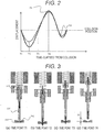
- valve element 101 elastically deforms by colliding with the valve seat 102 during valve closing and consequently bounces in the fuel injection valve in which switching between energization and de-energization of the coil 108 is carried out for opening and closing operation of the valve element 101.
- FIGS. 2 and 3 a description is provided of the bouncing phenomenon of the valve element in a typical fuel injection valve not adopting the present invention.
- displacement of the flange 113 of the valve element 101 is represented by D1
- displacement of the seat part 115 of the valve element is represented by D2.
- the flange 113 and the seat part 115 of the valve element colliding with the valve seat 102 both move in a direction of the valve seat 102. Thereafter, the displacement of the flange 113 of the valve element becomes minimum at a time point T2, and kinetic energy conserved just before the collision is converted into elastic energy of the valve element 101.
- the flange 113 After the displacement of the flange 113 of the valve element 101 reaches the minimum, the flange 113 starts to move in a direction away from the valve seat 102, that is to say, in a valve opening direction.
- the flange 113 reaches its maximum speed at a time point T3 where equilibrium is achieved by the urging force of the spring 110 and fuel pressure acting near the seat part 115, and restoring force of the valve element 101 rendered elastic and inertial force at the seat part 115 act to separate the seat part 115 away from the valve seat 102.
- T4 the bouncing finally takes place.
- An amount of bouncing corresponds to an axial distance G1 between the seat part 115 and the valve seat 102.
- a valve element 200 of the present invention includes a vibration absorbing part 208 formed by including a lower rigidity part 206 having reduced rigidity.
- the vibration absorbing part 208 thus formed easily vibrates axially of the valve element 101, that is to say, in valve opening and closing directions.
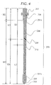
- the valve element 200 has such a shape as shown in FIG. 4 for the suppression of its bouncing.
- the valve element 200 capable of suppressing its bouncing has, between a surface 202 where spring force is transmitted to the valve element to urge the valve element 200 and a seat part 205 that seals in the fuel upon contact between the valve element 200 and the valve seat 102, the lower rigidity part 206 that has the axially reduced rigidity per axial unit length as compared with the seat part.
- the side having a center of gravity 201 of the valve element 200 has a value of rigidity K1 that is smaller than a value of rigidity K2 of the counterpart.
- a difference can be made smaller between a value of rigidity K3 of the valve element's side upstream of the center of gravity 201 of the valve element 200 having the lower rigidity part 206 and a value of rigidity K4 of the valve element's side extending from the center of gravity to the seat part.
- the values of rigidity K3, K4 be about the same, and this is achieved by, for example, a lower-rigidity-part length setting and a lower-rigidity-part width setting.
- the valve element 200 preferably has such a mass relationship that a mass M1 of the vibration absorbing part 208 positioned upstream of the lower rigidity part 206 is smaller than a mass M2 of a downstream side including the lower rigidity part 206.
- a structure for easy formation of a lower rigidity part that has reduced rigidity such as described above is as follows.
- the lower rigidity part 206 has a reduced diameter as compared with a maximal point 209, being a first maximal value appearing upstream of the seat part 205, and connects with connecting portions 207a, 207b on the respective upstream and downstream sides.
- the connecting portions 207a, 207b are each formed into a curved surface having at least one inflection point and are connected smoothly.
- an increased amount of deformation can be obtained for the vibration absorbing part 208 in a collision of the valve element 200 with the valve seat 102.
- the increased amount of deformation of the vibration absorbing part 208 facilitates conversion of kinetic energy conserved for the valve element in a valve closing process into an amount of deformation of the vibration absorbing part 208, so that a decreased amount of deformation can be obtained in a position of the collision between the seat part 205 and the valve seat 102.
- inertial force caused at the seat part 205 of the valve element 200 in a direction away from the valve seat 102 reduces, whereby the bouncing can be suppressed for the valve element.
- the lower rigidity part 206 has a length setting and a width setting so that the value of rigidity K3 of the valve element's side extending from the center of gravity 201 of the valve element 200 to the surface 202 where the urging force is transmitted is about the same as the value of rigidity K4 of the valve element's side extending from the center of gravity 201 to the seat part 205, or the difference between these values of rigidity is within 20 %, a rate of contribution of a natural vibration mode that is excited in the collision changes, meaning that a vibration mode such as to suppress bouncing can be excited with ease.
- a vibration mode that has a highest rate of contribution to the bouncing of the valve element is a vibration mode in which the surface 114 where the urging force is transmitted and the seat part 115 of the valve element vibrate in phase.
- the valve element that is provided with the above lower rigidity part 206 having its length and its width fixed so that the value of rigidity K3 of the valve element's side extending from the center of gravity 201 of the valve element to the surface 202 where the urging force is transmitted is about the same as the value of rigidity K4 of the valve element's side extending from the center of gravity to the seat part
- characteristic vectors in the primary natural vibration mode axially of the valve element alone thus have respective absolute values that are about the same and are in sign-inverted or anti-phase relationship in the vibration mode.
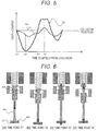
- FIG. 6 illustrates displacement D1 of the vibration absorbing part 208 of the valve element 200 and displacement D2 of the seat part 205 of the valve element 200 in a collision.
- FIG. 7 illustrates motion of the movable part of the fuel injection valve at each time point in the collision with arrows each indicating a direction of the motion.
- T1' the vibration absorbing part 208 and the seat part 205 of the valve element colliding with the valve seat both move in a direction of the valve seat 102.
- the displacement of the vibration absorbing part 208 of the valve element becomes minimum at a time point T2', and kinetic energy conserved just before the collision is converted into elastic energy of the valve element 200.
- the vibration absorbing part 208 of the valve element starts to move in a direction away from the valve seat 102, that is to say, in a valve opening direction.
- the vibration absorbing part 208 reaches its maximum speed at a time point T3' where equilibrium is achieved by the urging spring force and fuel pressure.
- the respective characteristic vectors of the vibration absorbing part 208 and the seat part 205 in the primary natural vibration mode axially of the valve element alone have the respective absolute values that are about the same and are in anti-phase relationship, so that at the time point T3' where the vibration absorbing part 208 reaches its maximum speed, the seat part 205 of the valve element moves in the valve closing direction that is opposite to the direction of the vibration absorbing part 208. Consequently, bouncing of the valve element 200 can be suppressed at a time point T4'.
- the bouncing of the valve element can be suppressed completely when the inertial force of the seat part 205 and restoring force of the valve element 200 become smaller than fuel pressure force.
- the bouncing of the valve element 200 can be suppressed because the seat part 205 moves in the direction that suppresses the bouncing of the valve element 200.
- the anti-phase vibration mode is easy to excite when the valve element 200 having the lower rigidity part 206 collides with the valve seat 102.
- This anti-phase vibration mode drivingly causes the seat part 115 to move in the valve closing direction opposite to the valve opening direction when an upper part of the valve element 200, that is, the vibration absorbing part 208 tries to move in the valve opening direction.
- the valve element 200 is effected in the direction that suppresses its bouncing, and the bouncing can be suppressed even under lower fuel pressure conditions.
- the connecting portions 207a, 207b connecting with the lower rigidity part 206 on the respective upstream and downstream sides are connected smoothly, so that concentration of stress can be suppressed in the collision.
- the bouncing is suppressed, whereby uncontrollable fuel injection can be suppressed.
- the force of the spring 110 that urges the valve element 200 is increased for improved speed just before the collision of the valve element 200 with the valve seat 102, bouncing can be suppressed.
- a smaller lift amount can be achieved for the valve element 200, and coarse particles can be reduced in a region where a fuel flow rate might otherwise drop due to increased pressure loss.
- the fuel injection valve can be provided as being capable of reducing harmful gas emitted from an automobile.
- the vibration absorbing part 208 performs vibration absorption, so that reduction of load that is transmitted by the valve element 200 to the valve seat 102 can be achieved. Consequently, not only can wear suppression be achieved in a collision between the valve element 200 and the valve seat 108, the fuel injection valve contributes to noise reduction, whereby an engine system having its noise reduced can be provided.
- the rigidity is reduced at one part as shown in FIG. 4 .
- similar effects can be obtained even in cases where the rigidity is reduced at a plurality of parts.
- FIG. 7 is a sectional view of a valve element 300 according to a second embodiment of the present invention. It is to be noted that the valve element 300 differs in shape from the valve element of the first embodiment. Descriptions of those components in the drawing that have the same reference marks as the components of the first embodiment are omitted.
- the valve element 300 of the second embodiment that is capable of suppressing its bouncing has, between a surface 302 where urging force of a spring 110 is transmitted to urge the valve element 300 and a seat part 205 that seals in fuel upon contact between the valve element 300 and the valve seat 102, a lightened part 306 that has axially reduced rigidity per axial unit length as compared with the seat part.
- the valve element 300 is divided into a side upstream of its center point 310 and a side downstream of the center point 310, the side having a center of gravity 301 of the valve element 300 has a value of rigidity K1' that is smaller than a value of rigidity K2' of the counterpart.
- a difference can be made smaller between a value of rigidity K3' of the valve element's side upstream of the center of gravity 301 of the valve element 300 having the lightened part 306 and a value of rigidity of the valve element's side extending from the center of gravity to the seat part K4'.
- the values of rigidity K3', K4' be about the same, and this is achieved by, for example, a lower-rigidity-part length setting and a lower-rigidity-part width setting that are not, however, restrictive.
- valve element 300 preferably has such a mass relationship that a mass M2 is larger than a mass M1 of a vibration absorbing part 308 positioned upstream of the lightened part 306. Consequently, the vibration absorbing part 308 absorbs energy in a collision, whereby the valve element 300 can suppress its bouncing.
- FIG. 8 is a sectional view of a valve element 400 according to a third embodiment of the present invention.
- This valve element 400 differs in shape from the valve elements of the first and second embodiments. Descriptions of those components in the drawing that have the same reference marks as the components of the first embodiment are omitted.
- the valve element 400 of the third embodiment that is capable of suppressing its bouncing has an elastic member 406 interposed between a surface 402 where urging force is transmitted to the valve element to urge the valve element 400 and a seat part 405 that seals in fuel upon contact between the valve element 400 and the valve seat 102.
- the valve element 400 is divided into a side upstream of its center point 310 and a side downstream of the center point 310, the side having a center of gravity 401 of the valve element 400 has a value of rigidity K1" that is smaller than a value of rigidity K2" of the counterpart.
- the valve element 400 preferably has such a mass relationship that a mass M2 is larger than a mass M1 of a vibration absorbing part 408 positioned upstream of the elastic member 406. With the above structure, the vibration absorbing part 408 absorbs energy in a collision, whereby the valve element 400 can suppress its bouncing.
Landscapes
- Engineering & Computer Science (AREA)
- Chemical & Material Sciences (AREA)
- Combustion & Propulsion (AREA)
- Mechanical Engineering (AREA)
- General Engineering & Computer Science (AREA)
- Physics & Mathematics (AREA)
- Electromagnetism (AREA)
- Fuel-Injection Apparatus (AREA)
Abstract
Description
- The present invention relates to fuel injection valves used for internal combustion engines, and more particularly to an electromagnetic fuel injection valve in which opening/closing operation of a valve element is carried out by passing current through a coil, whereby a magnetic flux is caused to a magnetic circuit including a movable element and a fixed iron core, thus causing magnetic attraction force to act so that the movable element is attracted toward the fixed iron core.
- For emission reduction of an internal combustion engine, a fuel injection valve (injector) that feeds fuel to the engine is required to precisely meter an injection quantity, thereby suppressing uncontrollable fuel injection. To that end, the injector is required to reduce its quantity of fuel injected while a valve element bounces on a valve seat during valve closing.
- A conventional fuel injection valve that is publicly known injects the fuel from its injection hole through use of magnetic attraction force generated by energization of a coil. In such a fuel injection valve, when the coil is energized, the magnetic attraction force is generated between a fixed iron core and a movable iron core. With the magnetic attraction force generated between the movable iron core and the fixed iron core, the movable iron core is attracted toward the fixed iron core, and force is transmitted to a valve element integral with the movable fixed iron core, thereby moving the valve element in a direction away from a valve seat. The movable iron core and the valve element that are integral with each other have their movement restricted by collision with the fixed iron core, thus identifying their stop positions. In this case, the movable iron core integral with the valve element collides with the fixed iron core and bounces back from the fixed iron core on impact of the collision. When the energization of the coil is brought to a halt, the magnetic attraction force acting between the movable iron core and the fixed iron core disappears, and when the magnetic attraction force becomes smaller than elastic force of an elastic member urging the valve element, the valve element starts to move toward the valve seat, that is to say, in a valve closing direction. The valve element and the movable iron core have their movement restricted by collision of the valve element with the valve seat, thus identifying their resting positions. In this case, the valve element collides with the valve seat and on impact of this collision, moves in the direction away from the valve seat. In cases where a space results between the valve element and the valve seat, uncontrollable fuel is injected exteriorly from the injection hole.
- To suppress such uncontrollable fuel injection, a structure such as disclosed in PTL 1 includes a movable iron core and a valve element that are provided separately.
- PTL 1:
JP 2010-014214 A - In the fuel injection valve, however, after the valve element collides with the valve seat, the valve element is rendered elastic under the influence of kinetic energy conserved in a valve closing process and thus undergoes elastic deformation. Thereafter, elastic energy conserved in a collision process translates into kinetic energy in the valve opening direction, that is, in the direction that separates the valve element away from the valve seat, thus causing bouncing. With the structure in which the movable iron core and the valve element are separated, reduction of initial energy of the valve element is possible but does not lead to suppression of a bouncing phenomenon that is caused as a result of the valve element being rendered elastic, so that the bouncing of the valve element that is caused as a result of the valve element being rendered elastic needs to be suppressed.
- An object of the present invention is therefore to provide a fuel injection valve configured to suppress bouncing of a valve element that is caused as a result of the valve element being rendered elastic when the valve element collides with a valve seat.
- To achieve the above object, a fuel injection valve according to the present invention includes a valve element configured to come into contact with a valve seat for closing an injection hole and to separate from the valve seat for unclosing the injection hole, an elastic member urging the valve element toward the valve seat, a movable iron core configured to be in and out of contact with the valve element, a fixed iron core opposed to the movable iron core, and a coil configured to generate electromagnetic force for moving the movable iron core, wherein at least one lower rigidity part having reduced rigidity per axial unit length is provided between a surface where urging force of the elastic member is transmitted to the valve element and a seat part whereat the valve element comes into contact with and separates from the valve seat, and wherein in a comparison between a value of axial rigidity of the valve element's side upstream of a center point axially of the valve element and a value of rigidity of the valve element's side downstream of the center point, the value of rigidity of the valve element's side having a center of gravity of the valve element is smaller.
- The present invention can suppress bouncing of the valve element that is caused as a result of the valve element being rendered elastic when the valve element collides with the valve seat.
-
- [
FIG. 1] FIG. 1 is a sectional view illustrating an example of a fuel injection valve according to a first embodiment of the present invention. - [
FIG. 2] FIG. 2 illustrates behavior of a valve element when the valve element bounces in the fuel injection valve according to the first embodiment of the present invention. - [
FIG. 3] FIG. 3 illustrates motion of the valve element when the valve element bounces in the fuel injection valve according to the first embodiment of the present invention. - [
FIG. 4] FIG. 4 is a sectional view of a valve element illustrated in an example of the fuel injection valve according to the first embodiment of the present invention. - [
FIG. 5] FIG. 5 illustrates behavior of the valve element when the valve element bounces in the fuel injection valve according to the first embodiment of the present invention. - [
FIG. 6] FIG. 6 illustrates motion of the valve element when the valve element bounces in the fuel injection valve according to the first embodiment of the present invention. - [
FIG. 7] FIG. 7 is a sectional view of a valve element illustrated in an example of a fuel injection valve according to a second embodiment of the present invention. - [
FIG. 8] FIG. 8 is a sectional view of a valve element illustrated in an example of a fuel injection valve according to a third embodiment of the present invention. - The present invention is detailed hereinafter.
- A valve element of the present invention includes a vibration absorbing part formed by including a lower rigidity part that has reduced rigidity per axial unit length as compared with another part of the valve element, and structurally, vibration is readily caused axially of the valve element for vibration absorption.
- Thus, displacement and force that are caused to the vibration absorbing part leads to vibration in phase with vibration of a seat part of the valve element, so that force in anti-phase with inertial force caused by vibration of the valve element is generated. Accordingly, displacement of the seat part of the valve element can be suppressed, and consequently, bouncing can be suppressed.
- Moreover, in a comparison between a value of rigidity of the valve element's side upstream of a center position axially of the valve element and a value of rigidity of the valve element's side downstream of the axial center position, the value of rigidity of the valve element's side having a center of gravity is smaller, whereby a difference between rigidity of the valve element's side upstream of the center of gravity of the valve element and a value of rigidity of the valve element's side downstream of the center of gravity is reduced. Accordingly, respective characteristic vectors of an upstream end point and a downstream end point of the valve element are of about the same value in a primary natural vibration mode axially of the valve element. The primary natural vibration mode axially of the valve element is such a vibration mode as to suppress the bouncing because vibrations at the respective upstream and downstream end points are in anti-phase relationship. For this reason, in a vibration mode with the valve element making contact with a valve seat, the vibration mode in which the vibrations occur in anti-phase relationship is easy to excite, whereby the bouncing of the valve element can be suppressed effectively. As such, a fuel injection valve capable of controlling a precise injection quantity can be provided.
- It is to be noted that although the above description is provided, taking an electromagnetic fuel injection valve for example, the fuel injection valve is not limited to the electromagnetic type. Effects are similar even in cases where the valve is driven by a piezoelectric element or a super magnetostrictive element.
- Embodiments of the present invention are described hereinafter with reference to the accompanying drawings.
-
FIG. 1 is a sectional view illustrating an electromagnetic fuel injection valve as an example of a fuel injection valve of the present invention. The electromagnetic fuel injection valve shown inFIG. 1 is an example used for a direct-injection gasoline engine but is also effective for a port-injection gasoline engine or as a fuel injection valve driven by a piezoelectric element or a magnetostrictive element. - In
FIG. 1 , fuel is fed from afuel feed port 112 into the fuel injection valve. The electromagneticfuel injection valve 100 accommodates avalve element 101 and is provided with avalve seat 102 in a position opposed to thevalve element 101. Thevalve seat 102 has a fuel injection hole that is not illustrated. Thevalve element 101 includes aflange 113 at its upstream end, and aspring 110 is provided to make contact with theflange 113. Thevalve element 101 is urged in a valve closing direction via asurface 114 that is provided on theflange 113 for transmitting urging force. Thevalve element 101 further includes aseat part 115 that forms a seal seat upon contact with thevalve seat 102. When acoil 108 is not being energized, thevalve element 101 is pressed by thespring 110 against thevalve seat 102, thus sealing in the fuel. - It is to be noted that with respect to an axis of the
fuel injection valve 100, a fuel-injection-hole side of thefuel injection valve 100 is explained as an upstream side, and a valve-seat side of thefuel injection valve 100 is explained as a downstream side. - When the
coil 108 shown inFIG. 1 is energized, a magnetic flux is caused to afixed iron core 107, ayoke 109, and amovable iron core 106 that form a magnetic circuit of the electromagnetic valve, thus producing magnetic attraction force in a gap between thefixed iron core 107 and themovable iron core 106. When the magnetic attraction force becomes greater than the urging force of thespring 110 and fuel pressure force, thevalve element 101 is attracted toward the fixediron core 107 via themovable iron core 106, thus establishing a valve opening state. - When the energization of the
coil 108 is brought to a halt, the magnetic flux within thefixed iron core 107 disappears, and the magnetic attraction force acting on themovable iron core 106 reduces accordingly and disappears shortly. When the force of theurging spring 110 that acts on thevalve element 101 becomes greater than the magnetic attraction force acting on themovable iron core 106, thevalve element 101 shifts downstream and comes into contact with theseat member 102, whereby the valve is closed. - The above description has been provided of the basic operation of the electromagnetic fuel injection valve. For the purpose of controlling a fuel injection quantity, the fuel injection valve is designed to control a time period during which the
valve element 101 is in opening condition through control of a time period during which thecoil 108 is energized. - However, there are cases where the
valve element 101 elastically deforms by colliding with thevalve seat 102 during valve closing and consequently bounces in the fuel injection valve in which switching between energization and de-energization of thecoil 108 is carried out for opening and closing operation of thevalve element 101. With reference toFIGS. 2 and 3 , a description is provided of the bouncing phenomenon of the valve element in a typical fuel injection valve not adopting the present invention. InFIG. 2 , displacement of theflange 113 of thevalve element 101 is represented by D1, while displacement of theseat part 115 of the valve element is represented by D2. - As shown in
FIGS. 2 and 3 , at a time point T1, theflange 113 and theseat part 115 of the valve element colliding with thevalve seat 102 both move in a direction of thevalve seat 102. Thereafter, the displacement of theflange 113 of the valve element becomes minimum at a time point T2, and kinetic energy conserved just before the collision is converted into elastic energy of thevalve element 101. - After the displacement of the
flange 113 of thevalve element 101 reaches the minimum, theflange 113 starts to move in a direction away from thevalve seat 102, that is to say, in a valve opening direction. Theflange 113 reaches its maximum speed at a time point T3 where equilibrium is achieved by the urging force of thespring 110 and fuel pressure acting near theseat part 115, and restoring force of thevalve element 101 rendered elastic and inertial force at theseat part 115 act to separate theseat part 115 away from thevalve seat 102. At a time point T4, the bouncing finally takes place. An amount of bouncing corresponds to an axial distance G1 between theseat part 115 and thevalve seat 102. Although separation of themovable iron core 113 enables reduction of initial energy of thevalve element 101, the bouncing phenomenon caused as a result of thevalve element 101 being rendered elastic cannot be suppressed, so that suppression of the bouncing that is caused as a result of thevalve element 101 being rendered elastic is required. - As described above, the suppression of the bouncing that results from the elastic deformation of the
valve element 101 in the collision of thevalve element 101 with thevalve seat 102 is the problem to be solved by the present invention. To achieve this object, that is to say, to enable bouncing suppression, avalve element 200 of the present invention includes avibration absorbing part 208 formed by including alower rigidity part 206 having reduced rigidity. Thevibration absorbing part 208 thus formed easily vibrates axially of thevalve element 101, that is to say, in valve opening and closing directions. - In the present invention, the
valve element 200 has such a shape as shown inFIG. 4 for the suppression of its bouncing. Structurally, thevalve element 200 capable of suppressing its bouncing has, between asurface 202 where spring force is transmitted to the valve element to urge thevalve element 200 and aseat part 205 that seals in the fuel upon contact between thevalve element 200 and thevalve seat 102, thelower rigidity part 206 that has the axially reduced rigidity per axial unit length as compared with the seat part. Moreover, when thevalve element 200 is divided into a side upstream of itscenter point 210 and a side downstream of thecenter point 210, the side having a center ofgravity 201 of thevalve element 200 has a value of rigidity K1 that is smaller than a value of rigidity K2 of the counterpart. With such a structure, a difference can be made smaller between a value of rigidity K3 of the valve element's side upstream of the center ofgravity 201 of thevalve element 200 having thelower rigidity part 206 and a value of rigidity K4 of the valve element's side extending from the center of gravity to the seat part. It is alternatively preferable that the values of rigidity K3, K4 be about the same, and this is achieved by, for example, a lower-rigidity-part length setting and a lower-rigidity-part width setting. Furthermore, thevalve element 200 preferably has such a mass relationship that a mass M1 of thevibration absorbing part 208 positioned upstream of thelower rigidity part 206 is smaller than a mass M2 of a downstream side including thelower rigidity part 206. - A structure for easy formation of a lower rigidity part that has reduced rigidity such as described above is as follows. The
lower rigidity part 206 has a reduced diameter as compared with amaximal point 209, being a first maximal value appearing upstream of theseat part 205, and connects with connectingportions portions - With the
lower rigidity part 206 achieved by outer-diameter reduction being provided between thesurface 202 where the urging force is transmitted and theseat part 205, an increased amount of deformation can be obtained for thevibration absorbing part 208 in a collision of thevalve element 200 with thevalve seat 102. The increased amount of deformation of thevibration absorbing part 208 facilitates conversion of kinetic energy conserved for the valve element in a valve closing process into an amount of deformation of thevibration absorbing part 208, so that a decreased amount of deformation can be obtained in a position of the collision between theseat part 205 and thevalve seat 102. With this decreased amount of deformation, inertial force caused at theseat part 205 of thevalve element 200 in a direction away from thevalve seat 102 reduces, whereby the bouncing can be suppressed for the valve element. In cases where thelower rigidity part 206 has a length setting and a width setting so that the value of rigidity K3 of the valve element's side extending from the center ofgravity 201 of thevalve element 200 to thesurface 202 where the urging force is transmitted is about the same as the value of rigidity K4 of the valve element's side extending from the center ofgravity 201 to theseat part 205, or the difference between these values of rigidity is within 20 %, a rate of contribution of a natural vibration mode that is excited in the collision changes, meaning that a vibration mode such as to suppress bouncing can be excited with ease. - With the typical fuel injection valve, a vibration mode that has a highest rate of contribution to the bouncing of the valve element is a vibration mode in which the
surface 114 where the urging force is transmitted and theseat part 115 of the valve element vibrate in phase. However, with the valve element that is provided with the abovelower rigidity part 206 having its length and its width fixed so that the value of rigidity K3 of the valve element's side extending from the center ofgravity 201 of the valve element to thesurface 202 where the urging force is transmitted is about the same as the value of rigidity K4 of the valve element's side extending from the center of gravity to the seat part, characteristic vectors in the primary natural vibration mode axially of the valve element alone thus have respective absolute values that are about the same and are in sign-inverted or anti-phase relationship in the vibration mode. - With reference to
FIGS. 6 and7 , a description is provided of a bounce suppressing mechanism of the anti-phase vibration mode of thevalve element 200.FIG. 6 illustrates displacement D1 of thevibration absorbing part 208 of thevalve element 200 and displacement D2 of theseat part 205 of thevalve element 200 in a collision.FIG. 7 illustrates motion of the movable part of the fuel injection valve at each time point in the collision with arrows each indicating a direction of the motion. At a time point T1', thevibration absorbing part 208 and theseat part 205 of the valve element colliding with the valve seat both move in a direction of thevalve seat 102. Thereafter, the displacement of thevibration absorbing part 208 of the valve element becomes minimum at a time point T2', and kinetic energy conserved just before the collision is converted into elastic energy of thevalve element 200. After the displacement of thevibration absorbing part 208 of the valve element reaches the minimum, thevibration absorbing part 208 of the valve element starts to move in a direction away from thevalve seat 102, that is to say, in a valve opening direction. Thevibration absorbing part 208 reaches its maximum speed at a time point T3' where equilibrium is achieved by the urging spring force and fuel pressure. At a time point T3', separation of theseat part 205 fromvalve seat 102 as a result of thevalve element 200 being rendered elastic can be suppressed by vibrational energy of thevibration absorbing part 208 because the mass M2 of the downstream side including thelower rigidity part 206 is larger than the mass M1 of the side upstream of thelower rigidity part 206. Moreover, the respective characteristic vectors of thevibration absorbing part 208 and theseat part 205 in the primary natural vibration mode axially of the valve element alone have the respective absolute values that are about the same and are in anti-phase relationship, so that at the time point T3' where thevibration absorbing part 208 reaches its maximum speed, theseat part 205 of the valve element moves in the valve closing direction that is opposite to the direction of thevibration absorbing part 208. Consequently, bouncing of thevalve element 200 can be suppressed at a time point T4'. Here, the bouncing of the valve element can be suppressed completely when the inertial force of theseat part 205 and restoring force of thevalve element 200 become smaller than fuel pressure force. Even in cases where the inertial force and the restoring force of thevalve element 200 become larger than the fuel pressure force, the bouncing of thevalve element 200 can be suppressed because theseat part 205 moves in the direction that suppresses the bouncing of thevalve element 200. - As described above, the anti-phase vibration mode is easy to excite when the
valve element 200 having thelower rigidity part 206 collides with thevalve seat 102. This anti-phase vibration mode drivingly causes theseat part 115 to move in the valve closing direction opposite to the valve opening direction when an upper part of thevalve element 200, that is, thevibration absorbing part 208 tries to move in the valve opening direction. As a result, thevalve element 200 is effected in the direction that suppresses its bouncing, and the bouncing can be suppressed even under lower fuel pressure conditions. Moreover, the connectingportions lower rigidity part 206 on the respective upstream and downstream sides are connected smoothly, so that concentration of stress can be suppressed in the collision. - With the above structure, the bouncing is suppressed, whereby uncontrollable fuel injection can be suppressed. Even in cases where, for example, the force of the
spring 110 that urges thevalve element 200 is increased for improved speed just before the collision of thevalve element 200 with thevalve seat 102, bouncing can be suppressed. Thus, in addition to improvement in responsiveness, with the improved speed at which valve closing is carried out by the urging force, a smaller lift amount can be achieved for thevalve element 200, and coarse particles can be reduced in a region where a fuel flow rate might otherwise drop due to increased pressure loss. - Consequently, the fuel injection valve can be provided as being capable of reducing harmful gas emitted from an automobile. According to the above structure, the
vibration absorbing part 208 performs vibration absorption, so that reduction of load that is transmitted by thevalve element 200 to thevalve seat 102 can be achieved. Consequently, not only can wear suppression be achieved in a collision between thevalve element 200 and thevalve seat 108, the fuel injection valve contributes to noise reduction, whereby an engine system having its noise reduced can be provided. - In the present embodiment described, the rigidity is reduced at one part as shown in
FIG. 4 . However, it is to be noted that similar effects can be obtained even in cases where the rigidity is reduced at a plurality of parts. -
FIG. 7 is a sectional view of avalve element 300 according to a second embodiment of the present invention. It is to be noted that thevalve element 300 differs in shape from the valve element of the first embodiment. Descriptions of those components in the drawing that have the same reference marks as the components of the first embodiment are omitted. - Structurally, the
valve element 300 of the second embodiment that is capable of suppressing its bouncing has, between asurface 302 where urging force of aspring 110 is transmitted to urge thevalve element 300 and aseat part 205 that seals in fuel upon contact between thevalve element 300 and thevalve seat 102, a lightened part 306 that has axially reduced rigidity per axial unit length as compared with the seat part. Moreover, when thevalve element 300 is divided into a side upstream of its center point 310 and a side downstream of the center point 310, the side having a center ofgravity 301 of thevalve element 300 has a value of rigidity K1' that is smaller than a value of rigidity K2' of the counterpart. With such a structure, a difference can be made smaller between a value of rigidity K3' of the valve element's side upstream of the center ofgravity 301 of thevalve element 300 having the lightened part 306 and a value of rigidity of the valve element's side extending from the center of gravity to the seat part K4'. It is alternatively preferable that the values of rigidity K3', K4' be about the same, and this is achieved by, for example, a lower-rigidity-part length setting and a lower-rigidity-part width setting that are not, however, restrictive. Furthermore, thevalve element 300 preferably has such a mass relationship that a mass M2 is larger than a mass M1 of a vibration absorbing part 308 positioned upstream of the lightened part 306. Consequently, the vibration absorbing part 308 absorbs energy in a collision, whereby thevalve element 300 can suppress its bouncing. -
FIG. 8 is a sectional view of avalve element 400 according to a third embodiment of the present invention. Thisvalve element 400 differs in shape from the valve elements of the first and second embodiments. Descriptions of those components in the drawing that have the same reference marks as the components of the first embodiment are omitted. - Structurally, the
valve element 400 of the third embodiment that is capable of suppressing its bouncing has anelastic member 406 interposed between asurface 402 where urging force is transmitted to the valve element to urge thevalve element 400 and aseat part 405 that seals in fuel upon contact between thevalve element 400 and thevalve seat 102. Moreover, when thevalve element 400 is divided into a side upstream of its center point 310 and a side downstream of the center point 310, the side having a center ofgravity 401 of thevalve element 400 has a value of rigidity K1" that is smaller than a value of rigidity K2" of the counterpart. With such a structure, a difference can be made smaller between a value of rigidity K3" of the valve element's side upstream of the center ofgravity 401 of thevalve element 400 having theelastic member 406 and a value of rigidity of the valve element's side extending from the center of gravity to the seat part K4". It is alternatively preferable that the values of rigidity K3", K4" be about the same, and this is achieved by a rigidity setting of theelastic member 406 that is not, however, restrictive. Furthermore, thevalve element 400 preferably has such a mass relationship that a mass M2 is larger than a mass M1 of a vibration absorbing part 408 positioned upstream of theelastic member 406. With the above structure, the vibration absorbing part 408 absorbs energy in a collision, whereby thevalve element 400 can suppress its bouncing. -
- 101, 200, 300, 400
- valve element
- 102
- valve seat
- 106
- movable iron core
- 107
- fixed iron core
- 108
- coil
- 109
- yoke
- 110
- spring
- 112
- fuel feed port
- 113
- flange
- 114, 202, 302, 402
- surface where urging force is transmitted
- 115, 205, 305, 405
- seat part
- 201, 301, 401
- center of gravity
- 206, 207a
- lower rigidity part
- 207a, 207b
- connecting portion
- 208, 308, 408
- vibration absorbing part
- 210, 310, 410
- center point
Claims (5)
- A fuel injection valve comprising a valve element configured to come into contact with a valve seat for closing an injection hole and to separate from the valve seat for unclosing the injection hole, an elastic member urging the valve element toward the valve seat, a movable iron core configured to be in and out of contact with the valve element, a fixed iron core opposed to the movable iron core, and a coil configured to generate electromagnetic force for moving the movable iron core,
wherein at least one lower rigidity part having reduced rigidity per axial unit length is provided between a surface where urging force of the elastic member is transmitted to the valve element and a seat part whereat the valve element comes into contact with and separates from the valve seat, and
wherein in a comparison between a value of axial rigidity of the valve element's side upstream of a center point axially of the valve element and a value of rigidity of the valve element's side downstream of the center point, the value of rigidity of the valve element's side having a center of gravity of the valve element is smaller. - The fuel injection valve according to claim 1, wherein a side of the valve element that is positioned upstream of the lower rigidity part has a smaller mass than a downstream side of the valve element that includes the lower rigidity part.
- The fuel injection valve according to claim 2, wherein a value of axial rigidity of the valve element's side upstream of the center of gravity of the valve element is about the same as a value of rigidity of the valve element's side downstream of the center of gravity.
- The fuel injection valve according to claim 3, wherein a difference between the value of axial rigidity of the valve element's side upstream of the center of gravity of the valve element and the value of rigidity of the valve element's side downstream of the center of gravity is within 20 %.
- The fuel injection valve according to claim 1, wherein the lower rigidity part of the valve element has a smaller outer diameter than a first maximal value appearing at the seat part.
Applications Claiming Priority (2)
| Application Number | Priority Date | Filing Date | Title |
|---|---|---|---|
| JP2015011929A JP6488134B2 (en) | 2015-01-26 | 2015-01-26 | Fuel injection valve |
| PCT/JP2016/050411 WO2016121444A1 (en) | 2015-01-26 | 2016-01-08 | Fuel injection valve |
Publications (3)
| Publication Number | Publication Date |
|---|---|
| EP3263885A1 true EP3263885A1 (en) | 2018-01-03 |
| EP3263885A4 EP3263885A4 (en) | 2018-10-24 |
| EP3263885B1 EP3263885B1 (en) | 2020-07-01 |
Family
ID=56543064
Family Applications (1)
| Application Number | Title | Priority Date | Filing Date |
|---|---|---|---|
| EP16743048.7A Not-in-force EP3263885B1 (en) | 2015-01-26 | 2016-01-08 | Fuel injection valve |
Country Status (5)
| Country | Link |
|---|---|
| US (1) | US10378496B2 (en) |
| EP (1) | EP3263885B1 (en) |
| JP (1) | JP6488134B2 (en) |
| CN (1) | CN107208592B (en) |
| WO (1) | WO2016121444A1 (en) |
Family Cites Families (47)
| Publication number | Priority date | Publication date | Assignee | Title |
|---|---|---|---|---|
| US2607368A (en) * | 1949-07-01 | 1952-08-19 | Tappan Stove Co | Solenoid operated valve |
| NL7607080A (en) * | 1976-06-28 | 1977-12-30 | Holec Nv | DEVICE FOR DELIVERING FUEL TO AN COMBUSTION ENGINE. |
| US4030668A (en) * | 1976-06-17 | 1977-06-21 | The Bendix Corporation | Electromagnetically operated fuel injection valve |
| DE3124854C2 (en) * | 1981-06-24 | 1985-03-14 | Reinhard 8057 Eching Mühlbauer | High pressure injection system with ultrasonic atomization |
| US4529165A (en) * | 1984-08-14 | 1985-07-16 | United Technologies Diesel Systems, Inc. | Solenoid valve |
| JPS6386372U (en) * | 1986-11-25 | 1988-06-06 | ||
| US5392745A (en) * | 1987-02-20 | 1995-02-28 | Servojet Electric Systems, Ltd. | Expanding cloud fuel injecting system |
| DE3825135A1 (en) * | 1988-07-23 | 1990-01-25 | Bosch Gmbh Robert | ELECTROMAGNETICALLY ACTUABLE VALVE |
| DE3905992A1 (en) * | 1989-02-25 | 1989-09-21 | Mesenich Gerhard | ELECTROMAGNETIC HIGH PRESSURE INJECTION VALVE |
| US5236173A (en) * | 1992-03-11 | 1993-08-17 | Siemens Automotive L.P. | Armature bounce damper |
| GB9301793D0 (en) * | 1993-01-29 | 1993-03-17 | Lucas Ind Plc | Fuel injection nozzle |
| US5544816A (en) * | 1994-08-18 | 1996-08-13 | Siemens Automotive L.P. | Housing for coil of solenoid-operated fuel injector |
| US5636827A (en) * | 1994-09-20 | 1997-06-10 | Siemens Automotive Corporation | Notched needle bounce eliminator |
| DE19625059A1 (en) * | 1996-06-22 | 1998-01-02 | Bosch Gmbh Robert | Injection valve, in particular for injecting fuel directly into a combustion chamber of an internal combustion engine |
| DE19632196B4 (en) * | 1996-08-09 | 2004-11-04 | Robert Bosch Gmbh | Electromagnetically actuated valve |
| US5921475A (en) * | 1997-08-07 | 1999-07-13 | Ford Motor Company | Automotive fuel injector |
| US6015103A (en) * | 1998-06-08 | 2000-01-18 | General Motors Corporation | Filter for fuel injector |
| US6279844B1 (en) * | 1999-03-18 | 2001-08-28 | Siemens Automotive Corporation | Fuel injector having fault tolerant connection |
| DE19946602A1 (en) * | 1999-09-29 | 2001-04-12 | Bosch Gmbh Robert | Fuel injector |
| DE19954864A1 (en) * | 1999-11-15 | 2001-05-23 | Bosch Gmbh Robert | Control valve and fuel injector provided with such a control valve |
| JP2001207939A (en) * | 2000-01-27 | 2001-08-03 | Mitsubishi Heavy Ind Ltd | Fuel injection nozzle |
| GB0005744D0 (en) * | 2000-03-10 | 2000-05-03 | Federal Mogul Ignition Uk Ltd | Fuel injector |
| US6390067B1 (en) * | 2000-08-10 | 2002-05-21 | Delphi Technologies, Inc. | Valve seat retainer for a fuel injector |
| US6543700B2 (en) * | 2000-12-11 | 2003-04-08 | Kimberly-Clark Worldwide, Inc. | Ultrasonic unitized fuel injector with ceramic valve body |
| US6663027B2 (en) * | 2000-12-11 | 2003-12-16 | Kimberly-Clark Worldwide, Inc. | Unitized injector modified for ultrasonically stimulated operation |
| SE519054C2 (en) * | 2001-05-10 | 2003-01-07 | Aneo Ab | Needle valve related arrangement |
| JP3899937B2 (en) * | 2002-01-18 | 2007-03-28 | 株式会社デンソー | Fuel injection valve |
| US6874703B2 (en) * | 2002-06-11 | 2005-04-05 | General Motors Corporation | Anti-bounce needle valve for a fuel injector |
| DE10305187A1 (en) * | 2003-02-08 | 2004-08-19 | Robert Bosch Gmbh | Fuel injection device, in particular for internal combustion engines with direct fuel injection |
| ITTO20040512A1 (en) * | 2004-07-23 | 2004-10-23 | Magneti Marelli Powertrain Spa | FUEL INJECTOR PROVIDED WITH HIGH FLEXIBILITY NEEDLE |
| DE102004037541B4 (en) * | 2004-08-03 | 2016-12-29 | Robert Bosch Gmbh | Fuel injector |
| JP2007154855A (en) * | 2005-12-08 | 2007-06-21 | Denso Corp | Fuel injection valve |
| JP4294671B2 (en) * | 2006-01-26 | 2009-07-15 | 株式会社デンソー | Fuel injection device |
| JP4527761B2 (en) * | 2007-10-30 | 2010-08-18 | 三菱電機株式会社 | Fuel injection valve and manufacturing method thereof |
| JP4591593B2 (en) * | 2008-02-13 | 2010-12-01 | 株式会社デンソー | Fuel injection valve |
| JP2010014214A (en) | 2008-07-04 | 2010-01-21 | Kamo Seiko Kk | Rolling ball type differential transmission |
| DE102008041165A1 (en) * | 2008-08-11 | 2010-02-18 | Robert Bosch Gmbh | Injection valve member |
| US8746514B2 (en) * | 2009-02-12 | 2014-06-10 | Nordson Corporation | Dispensing device with valve assembly having continuously smooth transition between tip and stem |
| CN201396230Y (en) * | 2009-05-12 | 2010-02-03 | 靳北彪 | Direct control type housing deformation fluid jetting device used for engine |
| CN201486716U (en) * | 2009-05-18 | 2010-05-26 | 山东菏泽华星油泵油嘴有限公司 | Flexible needle valve spray nozzle coupler |
| GB0919645D0 (en) * | 2009-11-10 | 2009-12-23 | Sentec Ltd | Flux switched fuel injector |
| EP2354530B1 (en) * | 2010-02-04 | 2013-04-10 | Delphi Technologies Holding S.à.r.l. | Needle for needle valve |
| US9133954B2 (en) * | 2010-09-06 | 2015-09-15 | Toyota Jidosha Kabushiki Kaisha | Electromagnetic linear valve |
| DE102011078732A1 (en) | 2011-07-06 | 2013-01-10 | Robert Bosch Gmbh | Device for injecting fuel, has valve needle and valve housing with valve seat, where valve needle closes aperture in valve seat, and valve needle has area with reduced rigidity |
| JP2013072298A (en) * | 2011-09-27 | 2013-04-22 | Hitachi Automotive Systems Ltd | Fuel injection valve |
| US9506429B2 (en) * | 2013-06-11 | 2016-11-29 | Cummins Inc. | System and method for control of fuel injector spray using ultrasonics |
| JP6347444B2 (en) * | 2014-09-12 | 2018-06-27 | 日立オートモティブシステムズ株式会社 | solenoid valve |
-
2015
- 2015-01-26 JP JP2015011929A patent/JP6488134B2/en not_active Expired - Fee Related
-
2016
- 2016-01-08 WO PCT/JP2016/050411 patent/WO2016121444A1/en not_active Ceased
- 2016-01-08 CN CN201680006167.6A patent/CN107208592B/en not_active Expired - Fee Related
- 2016-01-08 EP EP16743048.7A patent/EP3263885B1/en not_active Not-in-force
- 2016-01-08 US US15/545,930 patent/US10378496B2/en active Active
Also Published As
| Publication number | Publication date |
|---|---|
| EP3263885A4 (en) | 2018-10-24 |
| CN107208592A (en) | 2017-09-26 |
| JP6488134B2 (en) | 2019-03-20 |
| EP3263885B1 (en) | 2020-07-01 |
| US10378496B2 (en) | 2019-08-13 |
| US20170370337A1 (en) | 2017-12-28 |
| CN107208592B (en) | 2019-06-28 |
| WO2016121444A1 (en) | 2016-08-04 |
| JP2016138450A (en) | 2016-08-04 |
Similar Documents
| Publication | Publication Date | Title |
|---|---|---|
| US8857743B2 (en) | Fuel injection valve | |
| JP6087210B2 (en) | Fuel injection valve | |
| JP5822269B2 (en) | Electromagnetic fuel injection valve | |
| US8128009B2 (en) | Fuel injection valve | |
| JP2006017101A (en) | Fuel injection valve | |
| JP5982210B2 (en) | Electromagnetic fuel injection valve | |
| EP2336544A1 (en) | Anti-bounce mechanism for fuel injectors | |
| CN101463780A (en) | Fuel injection valve | |
| CN107709751B (en) | Electromagnetic valve | |
| JP2010084552A (en) | Solenoid type fuel injection valve | |
| JP5830492B2 (en) | High pressure pump | |
| US10280886B2 (en) | Fuel injection valve | |
| JP6613973B2 (en) | Fuel injection device | |
| EP3263885B1 (en) | Fuel injection valve | |
| JP4129689B2 (en) | Fuel injection valve | |
| US9394869B2 (en) | Fuel injector | |
| JP6020194B2 (en) | Fuel injection valve | |
| JP2005171845A (en) | Electromagnetic drive device and fuel injection valve using the same | |
| US11242830B2 (en) | Fuel injection valve | |
| JP6292272B2 (en) | Fuel injection valve | |
| JP2014098373A (en) | Fuel injection valve | |
| JP2006242148A (en) | Fuel injection valve | |
| WO2017043211A1 (en) | Fuel injection device | |
| JP2018123720A (en) | Fuel injection device | |
| JP2006009584A (en) | Fuel injection valve |
Legal Events
| Date | Code | Title | Description |
|---|---|---|---|
| STAA | Information on the status of an ep patent application or granted ep patent |
Free format text: STATUS: THE INTERNATIONAL PUBLICATION HAS BEEN MADE |
|
| PUAI | Public reference made under article 153(3) epc to a published international application that has entered the european phase |
Free format text: ORIGINAL CODE: 0009012 |
|
| STAA | Information on the status of an ep patent application or granted ep patent |
Free format text: STATUS: REQUEST FOR EXAMINATION WAS MADE |
|
| 17P | Request for examination filed |
Effective date: 20170828 |
|
| AK | Designated contracting states |
Kind code of ref document: A1 Designated state(s): AL AT BE BG CH CY CZ DE DK EE ES FI FR GB GR HR HU IE IS IT LI LT LU LV MC MK MT NL NO PL PT RO RS SE SI SK SM TR |
|
| AX | Request for extension of the european patent |
Extension state: BA ME |
|
| DAV | Request for validation of the european patent (deleted) | ||
| DAX | Request for extension of the european patent (deleted) | ||
| A4 | Supplementary search report drawn up and despatched |
Effective date: 20180924 |
|
| RIC1 | Information provided on ipc code assigned before grant |
Ipc: F16K 17/04 20060101ALI20180918BHEP Ipc: F16K 15/14 20060101ALI20180918BHEP Ipc: F02M 61/10 20060101AFI20180918BHEP Ipc: F02M 61/20 20060101ALI20180918BHEP Ipc: F02M 51/06 20060101ALI20180918BHEP Ipc: F16K 47/00 20060101ALI20180918BHEP Ipc: F02M 61/18 20060101ALI20180918BHEP Ipc: F02M 61/16 20060101ALI20180918BHEP |
|
| GRAP | Despatch of communication of intention to grant a patent |
Free format text: ORIGINAL CODE: EPIDOSNIGR1 |
|
| STAA | Information on the status of an ep patent application or granted ep patent |
Free format text: STATUS: GRANT OF PATENT IS INTENDED |
|
| INTG | Intention to grant announced |
Effective date: 20200305 |
|
| GRAS | Grant fee paid |
Free format text: ORIGINAL CODE: EPIDOSNIGR3 |
|
| GRAA | (expected) grant |
Free format text: ORIGINAL CODE: 0009210 |
|
| STAA | Information on the status of an ep patent application or granted ep patent |
Free format text: STATUS: THE PATENT HAS BEEN GRANTED |
|
| AK | Designated contracting states |
Kind code of ref document: B1 Designated state(s): AL AT BE BG CH CY CZ DE DK EE ES FI FR GB GR HR HU IE IS IT LI LT LU LV MC MK MT NL NO PL PT RO RS SE SI SK SM TR |
|
| REG | Reference to a national code |
Ref country code: AT Ref legal event code: REF Ref document number: 1286405 Country of ref document: AT Kind code of ref document: T Effective date: 20200715 Ref country code: CH Ref legal event code: EP |
|
| REG | Reference to a national code |
Ref country code: IE Ref legal event code: FG4D |
|
| REG | Reference to a national code |
Ref country code: DE Ref legal event code: R096 Ref document number: 602016039127 Country of ref document: DE |
|
| REG | Reference to a national code |
Ref country code: LT Ref legal event code: MG4D |
|
| PG25 | Lapsed in a contracting state [announced via postgrant information from national office to epo] |
Ref country code: BG Free format text: LAPSE BECAUSE OF FAILURE TO SUBMIT A TRANSLATION OF THE DESCRIPTION OR TO PAY THE FEE WITHIN THE PRESCRIBED TIME-LIMIT Effective date: 20201001 |
|
| REG | Reference to a national code |
Ref country code: NL Ref legal event code: MP Effective date: 20200701 |
|
| REG | Reference to a national code |
Ref country code: AT Ref legal event code: MK05 Ref document number: 1286405 Country of ref document: AT Kind code of ref document: T Effective date: 20200701 |
|
| PG25 | Lapsed in a contracting state [announced via postgrant information from national office to epo] |
Ref country code: FI Free format text: LAPSE BECAUSE OF FAILURE TO SUBMIT A TRANSLATION OF THE DESCRIPTION OR TO PAY THE FEE WITHIN THE PRESCRIBED TIME-LIMIT Effective date: 20200701 Ref country code: CZ Free format text: LAPSE BECAUSE OF FAILURE TO SUBMIT A TRANSLATION OF THE DESCRIPTION OR TO PAY THE FEE WITHIN THE PRESCRIBED TIME-LIMIT Effective date: 20200701 Ref country code: ES Free format text: LAPSE BECAUSE OF FAILURE TO SUBMIT A TRANSLATION OF THE DESCRIPTION OR TO PAY THE FEE WITHIN THE PRESCRIBED TIME-LIMIT Effective date: 20200701 Ref country code: PT Free format text: LAPSE BECAUSE OF FAILURE TO SUBMIT A TRANSLATION OF THE DESCRIPTION OR TO PAY THE FEE WITHIN THE PRESCRIBED TIME-LIMIT Effective date: 20201102 Ref country code: LT Free format text: LAPSE BECAUSE OF FAILURE TO SUBMIT A TRANSLATION OF THE DESCRIPTION OR TO PAY THE FEE WITHIN THE PRESCRIBED TIME-LIMIT Effective date: 20200701 Ref country code: HR Free format text: LAPSE BECAUSE OF FAILURE TO SUBMIT A TRANSLATION OF THE DESCRIPTION OR TO PAY THE FEE WITHIN THE PRESCRIBED TIME-LIMIT Effective date: 20200701 Ref country code: AT Free format text: LAPSE BECAUSE OF FAILURE TO SUBMIT A TRANSLATION OF THE DESCRIPTION OR TO PAY THE FEE WITHIN THE PRESCRIBED TIME-LIMIT Effective date: 20200701 Ref country code: SE Free format text: LAPSE BECAUSE OF FAILURE TO SUBMIT A TRANSLATION OF THE DESCRIPTION OR TO PAY THE FEE WITHIN THE PRESCRIBED TIME-LIMIT Effective date: 20200701 Ref country code: NO Free format text: LAPSE BECAUSE OF FAILURE TO SUBMIT A TRANSLATION OF THE DESCRIPTION OR TO PAY THE FEE WITHIN THE PRESCRIBED TIME-LIMIT Effective date: 20201001 Ref country code: GR Free format text: LAPSE BECAUSE OF FAILURE TO SUBMIT A TRANSLATION OF THE DESCRIPTION OR TO PAY THE FEE WITHIN THE PRESCRIBED TIME-LIMIT Effective date: 20201002 |
|
| PG25 | Lapsed in a contracting state [announced via postgrant information from national office to epo] |
Ref country code: IS Free format text: LAPSE BECAUSE OF FAILURE TO SUBMIT A TRANSLATION OF THE DESCRIPTION OR TO PAY THE FEE WITHIN THE PRESCRIBED TIME-LIMIT Effective date: 20201101 Ref country code: PL Free format text: LAPSE BECAUSE OF FAILURE TO SUBMIT A TRANSLATION OF THE DESCRIPTION OR TO PAY THE FEE WITHIN THE PRESCRIBED TIME-LIMIT Effective date: 20200701 Ref country code: RS Free format text: LAPSE BECAUSE OF FAILURE TO SUBMIT A TRANSLATION OF THE DESCRIPTION OR TO PAY THE FEE WITHIN THE PRESCRIBED TIME-LIMIT Effective date: 20200701 Ref country code: LV Free format text: LAPSE BECAUSE OF FAILURE TO SUBMIT A TRANSLATION OF THE DESCRIPTION OR TO PAY THE FEE WITHIN THE PRESCRIBED TIME-LIMIT Effective date: 20200701 |
|
| REG | Reference to a national code |
Ref country code: DE Ref legal event code: R082 Ref document number: 602016039127 Country of ref document: DE Representative=s name: MERH-IP MATIAS ERNY REICHL HOFFMANN PATENTANWA, DE Ref country code: DE Ref legal event code: R081 Ref document number: 602016039127 Country of ref document: DE Owner name: HITACHI ASTEMO, LTD., HITACHINAKA-SHI, JP Free format text: FORMER OWNER: HITACHI AUTOMOTIVE SYSTEMS, LTD., HITACHINAKA-SHI, IBARAKI, JP |
|
| PG25 | Lapsed in a contracting state [announced via postgrant information from national office to epo] |
Ref country code: NL Free format text: LAPSE BECAUSE OF FAILURE TO SUBMIT A TRANSLATION OF THE DESCRIPTION OR TO PAY THE FEE WITHIN THE PRESCRIBED TIME-LIMIT Effective date: 20200701 |
|
| REG | Reference to a national code |
Ref country code: DE Ref legal event code: R097 Ref document number: 602016039127 Country of ref document: DE |
|
| PG25 | Lapsed in a contracting state [announced via postgrant information from national office to epo] |
Ref country code: DK Free format text: LAPSE BECAUSE OF FAILURE TO SUBMIT A TRANSLATION OF THE DESCRIPTION OR TO PAY THE FEE WITHIN THE PRESCRIBED TIME-LIMIT Effective date: 20200701 Ref country code: RO Free format text: LAPSE BECAUSE OF FAILURE TO SUBMIT A TRANSLATION OF THE DESCRIPTION OR TO PAY THE FEE WITHIN THE PRESCRIBED TIME-LIMIT Effective date: 20200701 Ref country code: SM Free format text: LAPSE BECAUSE OF FAILURE TO SUBMIT A TRANSLATION OF THE DESCRIPTION OR TO PAY THE FEE WITHIN THE PRESCRIBED TIME-LIMIT Effective date: 20200701 Ref country code: IT Free format text: LAPSE BECAUSE OF FAILURE TO SUBMIT A TRANSLATION OF THE DESCRIPTION OR TO PAY THE FEE WITHIN THE PRESCRIBED TIME-LIMIT Effective date: 20200701 Ref country code: EE Free format text: LAPSE BECAUSE OF FAILURE TO SUBMIT A TRANSLATION OF THE DESCRIPTION OR TO PAY THE FEE WITHIN THE PRESCRIBED TIME-LIMIT Effective date: 20200701 |
|
| PLBE | No opposition filed within time limit |
Free format text: ORIGINAL CODE: 0009261 |
|
| STAA | Information on the status of an ep patent application or granted ep patent |
Free format text: STATUS: NO OPPOSITION FILED WITHIN TIME LIMIT |
|
| PG25 | Lapsed in a contracting state [announced via postgrant information from national office to epo] |
Ref country code: AL Free format text: LAPSE BECAUSE OF FAILURE TO SUBMIT A TRANSLATION OF THE DESCRIPTION OR TO PAY THE FEE WITHIN THE PRESCRIBED TIME-LIMIT Effective date: 20200701 |
|
| 26N | No opposition filed |
Effective date: 20210406 |
|
| PG25 | Lapsed in a contracting state [announced via postgrant information from national office to epo] |
Ref country code: SK Free format text: LAPSE BECAUSE OF FAILURE TO SUBMIT A TRANSLATION OF THE DESCRIPTION OR TO PAY THE FEE WITHIN THE PRESCRIBED TIME-LIMIT Effective date: 20200701 |
|
| PG25 | Lapsed in a contracting state [announced via postgrant information from national office to epo] |
Ref country code: SI Free format text: LAPSE BECAUSE OF FAILURE TO SUBMIT A TRANSLATION OF THE DESCRIPTION OR TO PAY THE FEE WITHIN THE PRESCRIBED TIME-LIMIT Effective date: 20200701 Ref country code: MC Free format text: LAPSE BECAUSE OF FAILURE TO SUBMIT A TRANSLATION OF THE DESCRIPTION OR TO PAY THE FEE WITHIN THE PRESCRIBED TIME-LIMIT Effective date: 20200701 |
|
| REG | Reference to a national code |
Ref country code: CH Ref legal event code: PL |
|
| GBPC | Gb: european patent ceased through non-payment of renewal fee |
Effective date: 20210108 |
|
| PG25 | Lapsed in a contracting state [announced via postgrant information from national office to epo] |
Ref country code: LU Free format text: LAPSE BECAUSE OF NON-PAYMENT OF DUE FEES Effective date: 20210108 |
|
| REG | Reference to a national code |
Ref country code: BE Ref legal event code: MM Effective date: 20210131 |
|
| PG25 | Lapsed in a contracting state [announced via postgrant information from national office to epo] |
Ref country code: FR Free format text: LAPSE BECAUSE OF NON-PAYMENT OF DUE FEES Effective date: 20210131 |
|
| PG25 | Lapsed in a contracting state [announced via postgrant information from national office to epo] |
Ref country code: CH Free format text: LAPSE BECAUSE OF NON-PAYMENT OF DUE FEES Effective date: 20210131 Ref country code: LI Free format text: LAPSE BECAUSE OF NON-PAYMENT OF DUE FEES Effective date: 20210131 Ref country code: GB Free format text: LAPSE BECAUSE OF NON-PAYMENT OF DUE FEES Effective date: 20210108 |
|
| PG25 | Lapsed in a contracting state [announced via postgrant information from national office to epo] |
Ref country code: IE Free format text: LAPSE BECAUSE OF NON-PAYMENT OF DUE FEES Effective date: 20210108 |
|
| PG25 | Lapsed in a contracting state [announced via postgrant information from national office to epo] |
Ref country code: IS Free format text: LAPSE BECAUSE OF FAILURE TO SUBMIT A TRANSLATION OF THE DESCRIPTION OR TO PAY THE FEE WITHIN THE PRESCRIBED TIME-LIMIT Effective date: 20201101 |
|
| PG25 | Lapsed in a contracting state [announced via postgrant information from national office to epo] |
Ref country code: BE Free format text: LAPSE BECAUSE OF NON-PAYMENT OF DUE FEES Effective date: 20210131 |
|
| PGFP | Annual fee paid to national office [announced via postgrant information from national office to epo] |
Ref country code: DE Payment date: 20221130 Year of fee payment: 8 |
|
| PG25 | Lapsed in a contracting state [announced via postgrant information from national office to epo] |
Ref country code: CY Free format text: LAPSE BECAUSE OF FAILURE TO SUBMIT A TRANSLATION OF THE DESCRIPTION OR TO PAY THE FEE WITHIN THE PRESCRIBED TIME-LIMIT Effective date: 20200701 |
|
| PG25 | Lapsed in a contracting state [announced via postgrant information from national office to epo] |
Ref country code: HU Free format text: LAPSE BECAUSE OF FAILURE TO SUBMIT A TRANSLATION OF THE DESCRIPTION OR TO PAY THE FEE WITHIN THE PRESCRIBED TIME-LIMIT; INVALID AB INITIO Effective date: 20160108 |
|
| PG25 | Lapsed in a contracting state [announced via postgrant information from national office to epo] |
Ref country code: MK Free format text: LAPSE BECAUSE OF FAILURE TO SUBMIT A TRANSLATION OF THE DESCRIPTION OR TO PAY THE FEE WITHIN THE PRESCRIBED TIME-LIMIT Effective date: 20200701 |
|
| PG25 | Lapsed in a contracting state [announced via postgrant information from national office to epo] |
Ref country code: TR Free format text: LAPSE BECAUSE OF FAILURE TO SUBMIT A TRANSLATION OF THE DESCRIPTION OR TO PAY THE FEE WITHIN THE PRESCRIBED TIME-LIMIT Effective date: 20200701 |
|
| REG | Reference to a national code |
Ref country code: DE Ref legal event code: R119 Ref document number: 602016039127 Country of ref document: DE |
|
| PG25 | Lapsed in a contracting state [announced via postgrant information from national office to epo] |
Ref country code: MT Free format text: LAPSE BECAUSE OF FAILURE TO SUBMIT A TRANSLATION OF THE DESCRIPTION OR TO PAY THE FEE WITHIN THE PRESCRIBED TIME-LIMIT Effective date: 20200701 |
|
| PG25 | Lapsed in a contracting state [announced via postgrant information from national office to epo] |
Ref country code: DE Free format text: LAPSE BECAUSE OF NON-PAYMENT OF DUE FEES Effective date: 20240801 |
|
| PG25 | Lapsed in a contracting state [announced via postgrant information from national office to epo] |
Ref country code: DE Free format text: LAPSE BECAUSE OF NON-PAYMENT OF DUE FEES Effective date: 20240801 |