EP3263841A2 - Turbinengehäuseverstärkung - Google Patents
Turbinengehäuseverstärkung Download PDFInfo
- Publication number
- EP3263841A2 EP3263841A2 EP17176961.5A EP17176961A EP3263841A2 EP 3263841 A2 EP3263841 A2 EP 3263841A2 EP 17176961 A EP17176961 A EP 17176961A EP 3263841 A2 EP3263841 A2 EP 3263841A2
- Authority
- EP
- European Patent Office
- Prior art keywords
- boss
- stiffness
- turbine case
- turbine
- case
- Prior art date
- Legal status (The legal status is an assumption and is not a legal conclusion. Google has not performed a legal analysis and makes no representation as to the accuracy of the status listed.)
- Granted
Links
Images



Classifications
-
- F—MECHANICAL ENGINEERING; LIGHTING; HEATING; WEAPONS; BLASTING
- F01—MACHINES OR ENGINES IN GENERAL; ENGINE PLANTS IN GENERAL; STEAM ENGINES
- F01D—NON-POSITIVE DISPLACEMENT MACHINES OR ENGINES, e.g. STEAM TURBINES
- F01D25/00—Component parts, details, or accessories, not provided for in, or of interest apart from, other groups
- F01D25/24—Casings; Casing parts, e.g. diaphragms, casing fastenings
-
- F—MECHANICAL ENGINEERING; LIGHTING; HEATING; WEAPONS; BLASTING
- F01—MACHINES OR ENGINES IN GENERAL; ENGINE PLANTS IN GENERAL; STEAM ENGINES
- F01D—NON-POSITIVE DISPLACEMENT MACHINES OR ENGINES, e.g. STEAM TURBINES
- F01D25/00—Component parts, details, or accessories, not provided for in, or of interest apart from, other groups
- F01D25/28—Supporting or mounting arrangements, e.g. for turbine casing
-
- F—MECHANICAL ENGINEERING; LIGHTING; HEATING; WEAPONS; BLASTING
- F01—MACHINES OR ENGINES IN GENERAL; ENGINE PLANTS IN GENERAL; STEAM ENGINES
- F01D—NON-POSITIVE DISPLACEMENT MACHINES OR ENGINES, e.g. STEAM TURBINES
- F01D9/00—Stators
- F01D9/02—Nozzles; Nozzle boxes; Stator blades; Guide conduits, e.g. individual nozzles
- F01D9/04—Nozzles; Nozzle boxes; Stator blades; Guide conduits, e.g. individual nozzles forming ring or sector
- F01D9/041—Nozzles; Nozzle boxes; Stator blades; Guide conduits, e.g. individual nozzles forming ring or sector using blades
-
- F—MECHANICAL ENGINEERING; LIGHTING; HEATING; WEAPONS; BLASTING
- F05—INDEXING SCHEMES RELATING TO ENGINES OR PUMPS IN VARIOUS SUBCLASSES OF CLASSES F01-F04
- F05D—INDEXING SCHEME FOR ASPECTS RELATING TO NON-POSITIVE-DISPLACEMENT MACHINES OR ENGINES, GAS-TURBINES OR JET-PROPULSION PLANTS
- F05D2220/00—Application
- F05D2220/30—Application in turbines
- F05D2220/32—Application in turbines in gas turbines
-
- F—MECHANICAL ENGINEERING; LIGHTING; HEATING; WEAPONS; BLASTING
- F05—INDEXING SCHEMES RELATING TO ENGINES OR PUMPS IN VARIOUS SUBCLASSES OF CLASSES F01-F04
- F05D—INDEXING SCHEME FOR ASPECTS RELATING TO NON-POSITIVE-DISPLACEMENT MACHINES OR ENGINES, GAS-TURBINES OR JET-PROPULSION PLANTS
- F05D2230/00—Manufacture
- F05D2230/10—Manufacture by removing material
-
- F—MECHANICAL ENGINEERING; LIGHTING; HEATING; WEAPONS; BLASTING
- F05—INDEXING SCHEMES RELATING TO ENGINES OR PUMPS IN VARIOUS SUBCLASSES OF CLASSES F01-F04
- F05D—INDEXING SCHEME FOR ASPECTS RELATING TO NON-POSITIVE-DISPLACEMENT MACHINES OR ENGINES, GAS-TURBINES OR JET-PROPULSION PLANTS
- F05D2230/00—Manufacture
- F05D2230/20—Manufacture essentially without removing material
- F05D2230/21—Manufacture essentially without removing material by casting
-
- F—MECHANICAL ENGINEERING; LIGHTING; HEATING; WEAPONS; BLASTING
- F05—INDEXING SCHEMES RELATING TO ENGINES OR PUMPS IN VARIOUS SUBCLASSES OF CLASSES F01-F04
- F05D—INDEXING SCHEME FOR ASPECTS RELATING TO NON-POSITIVE-DISPLACEMENT MACHINES OR ENGINES, GAS-TURBINES OR JET-PROPULSION PLANTS
- F05D2230/00—Manufacture
- F05D2230/20—Manufacture essentially without removing material
- F05D2230/23—Manufacture essentially without removing material by permanently joining parts together
- F05D2230/232—Manufacture essentially without removing material by permanently joining parts together by welding
- F05D2230/237—Brazing
-
- F—MECHANICAL ENGINEERING; LIGHTING; HEATING; WEAPONS; BLASTING
- F05—INDEXING SCHEMES RELATING TO ENGINES OR PUMPS IN VARIOUS SUBCLASSES OF CLASSES F01-F04
- F05D—INDEXING SCHEME FOR ASPECTS RELATING TO NON-POSITIVE-DISPLACEMENT MACHINES OR ENGINES, GAS-TURBINES OR JET-PROPULSION PLANTS
- F05D2230/00—Manufacture
- F05D2230/30—Manufacture with deposition of material
Definitions
- the present disclosure relates to turbine cases and, more particularly, to bosses for turbine cases of gas turbine engines.
- Turbine frame cases such as a mid-turbine frame outer case, may contain bosses used to attach external parts. At some locations where no external parts are attached, the bosses may be in an unattached condition. Removing the boss from the case may create asymmetric stiffness. Accordingly, unused bosses may be left intact to maintain symmetric stiffness of the case.
- a stiffness boss for a turbine case of a gas turbine engine includes a head portion disposed on an outer case surface of the turbine case, the head portion configured to provide rigidity in response to a transverse load being applied to the turbine case in a transverse direction.
- the stiffness boss also includes a leg portion disposed on the outer case surface of the turbine case and connected to the head portion, the leg portion configured to provide rigidity in response to an axial load being applied to the turbine case in an axial direction, such that deformation of the turbine case is resisted.
- the head portion and the leg portion may provide rigidity in response to a radial load being applied to the turbine case in a radially inward direction.
- the head portion may have a head length and head width determined to provide optimized rigidity and minimized weight.
- the leg portion may have a leg length and leg width determined to provide optimized rigidity and minimized weight.
- the head portion may be flat and may be substantially parallel to an axis of the gas turbine engine.
- the leg portion may be flat and sloped radially inward.
- the head portion and the leg portion may be connected to the outer case surface by a filleted portion.
- the filleted portion may be curved radially inward.
- a turbine case of a gas turbine engine includes an outer case surface.
- the turbine case also includes a support member boss configured to secure support structures of the gas turbine engine.
- the turbine case also includes a stiffness boss disposed on the outer case surface and configured to provide rigidity in response to one or more loads applied to the turbine case, the stiffness boss being different from the support member boss.
- the stiffness boss may be a gusseted boss configured to provide rigidity in response to at least one of a transverse load, an axial load, or a radial load applied to the turbine case.
- the stiffness boss may comprise a head portion configured to provide rigidity in response to a transverse load being applied to the turbine case in a transverse direction, and a leg portion configured to provide rigidity in response to an axial load being applied to the turbine case in an axial direction, such that deformation of the outer case is resisted.
- the head portion and the leg portion may provide rigidity in response to a radial load being applied to the turbine case in a radially inward direction.
- the head portion may have a head length and head width determined to provide optimized rigidity and minimized weight.
- the leg portion may have a leg length and leg width determined to provide optimized rigidity and minimized weight.
- the head portion may be flat and may be substantially parallel to an axis of the gas turbine engine.
- the leg portion may be flat and sloped radially inward.
- the stiffness boss may be at least one of welded, brazed, additively manufactured, machined, or cast on the outer case surface.
- the stiffness boss and the turbine case may be made of different materials.
- a method of fabricating a turbine case includes disposing a head portion of a stiffness boss on an outer surface of the turbine case, the head portion configured to provide rigidity in response to a transverse load being applied to the turbine case.
- the method further includes disposing a leg portion of the stiffness boss on the outer surface of the turbine case, the leg portion configured to provide rigidity in response to an axial load being applied to the turbine case.
- the method may further include determining a head length and a head width of the head portion by optimizing rigidity and minimizing weight and determining a leg length and a leg width of the leg portion by optimizing rigidity and minimizing weight.
- any reference to attached, fixed, connected or the like may include permanent, removable, temporary, partial, full and/or any other possible attachment option. Additionally, any reference to without contact (or similar phrases) may also include reduced contact or minimal contact.
- “approximately” or “substantially” may refer to a measurement or dimension within 10% of the corresponding measurement of the referenced object. For example, a length that is substantially or approximately equal to a length of 10 feet may be between 9 feet and 11 feet.
- any reference to singular includes plural embodiments, and any reference to more than one component or step may include a singular embodiment or step.
- Surface shading lines may be used throughout the figures to denote different parts but not necessarily to denote the same or different materials.
- aft refers to the direction associated with the exhaust (e.g., the back end) of a gas turbine engine.
- forward refers to the direction associated with the intake (e.g., the front end) of a gas turbine engine.
- a first component that is "radially outward" of a second component means that a first component is positioned at a greater distance away from the engine central longitudinal axis, than the second component.
- a first component that is “radially inward” of a second component means that the first component is positioned closer to the engine central longitudinal axis, than the second component.
- a first component that is radially inward of a second component rotates through a circumferentially shorter path than the second component.
- the terminology “radially outward” and “radially inward” may also be used relative to references other than the engine central longitudinal axis.
- Gas turbine engine 2 may be a two-spool turbofan that generally incorporates a fan section 4, a compressor section 6, a combustor section 8 and a turbine section 10.
- Alternative engines may include, for example, an augmentor section among other systems or features.
- fan section 4 can drive air along a bypass flow-path B while compressor section 6 can drive air along a core flow-path C for compression and communication into combustor section 8 then expansion through turbine section 10.
- turbofan gas turbine engine 2 depicted as a turbofan gas turbine engine 2 herein, it should be understood that the concepts described herein are not limited to use with turbofans as the teachings may be applied to other types of turbine engines including three-spool architectures.
- Gas turbine engine 2 may generally comprise a low speed spool 12 and a high speed spool 14 mounted for rotation about an engine central longitudinal axis X-X' relative to an engine static structure 16 via several bearing systems 18-1, 18-2, and 18-3. It should be understood that various bearing systems at various locations may alternatively or additionally be provided, including for example, bearing system 18-1, bearing system 18-2, and bearing system 18-3.
- Low speed spool 12 may generally comprise an inner shaft 20 that interconnects a fan 22, a low pressure compressor section 24 (e.g., a first compressor section) and a low pressure turbine section 26 (e.g., a first turbine section).
- Inner shaft 20 may be connected to fan 22 through a geared architecture 28 that can drive the fan 22 at a lower speed than low speed spool 12.
- Geared architecture 28 may comprise a gear assembly 42 enclosed within a gear housing 44.
- Gear assembly 42 couples the inner shaft 20 to a rotating fan structure.
- High speed spool 14 may comprise an outer shaft 30 that interconnects a high pressure compressor section 32 (e.g., second compressor section) and high pressure turbine section 34 (e.g., second turbine section).
- a combustor 36 may be located between high pressure compressor section 32 and high pressure turbine section 34.
- a mid-turbine frame 38 of engine static structure 16 may be located generally between high pressure turbine section 34 and low pressure turbine section 26.
- Mid-turbine frame 38 may support one or more bearing systems 18 (such as 18-3) in turbine section 10.
- Inner shaft 20 and outer shaft 30 may be concentric and rotate via bearing systems 18 about the engine central longitudinal axis X-X', which is collinear with their longitudinal axes.
- a "high pressure" compressor or turbine experiences a higher pressure than a corresponding "low pressure” compressor or turbine.
- the core airflow C may be compressed by low pressure compressor section 24 then high pressure compressor section 32, mixed and burned with fuel in combustor 36, then expanded over high pressure turbine section 34 and low pressure turbine section 26.
- Mid-turbine frame 38 includes airfoils 40, which are in the core airflow path. Turbines 26, 34 rotationally drive the respective low speed spool 12 and high speed spool 14 in response to the expansion.
- Gas turbine engine 2 may be, for example, a high-bypass geared aircraft engine.
- the bypass ratio of gas turbine engine 2 may be greater than about six.
- the bypass ratio of gas turbine engine 2 may be greater than ten.
- geared architecture 28 may be an epicyclic gear train, such as a star gear system (sun gear in meshing engagement with a plurality of star gears supported by a carrier and in meshing engagement with a ring gear) or other gear system.
- Geared architecture 28 may have a gear reduction ratio of greater than about 2.3 and low pressure turbine section 26 may have a pressure ratio that is greater than about 5.
- the bypass ratio of gas turbine engine 2 is greater than about ten.
- the diameter of fan 22 may be significantly larger than that of the low pressure compressor section 24, and the low pressure turbine section 26 may have a pressure ratio that is greater than about 5:1.
- Low pressure turbine section 26 pressure ratio may be measured prior to inlet of low pressure turbine section 26 as related to the pressure at the outlet of low pressure turbine section 26 prior to an exhaust nozzle. It should be understood, however, that the above parameters are exemplary of various embodiments of a suitable geared architecture engine and that the present disclosure contemplates other turbine engines including direct drive turbofans.
- next generation of turbofan engines may be designed for higher efficiency, which may be associated with higher pressure ratios and higher temperatures in the high speed spool 14. These higher operating temperatures and pressure ratios may create operating environments that may cause thermal loads that are higher than thermal loads conventionally encountered, which may shorten the operational life of current components.
- operating conditions in high pressure compressor section 32 may be approximately 1400 °F (approximately 760 °C) or more, and operating conditions in combustor 36 may be higher.
- combustor section 8 may comprise one or more combustor 36.
- the core airflow C may be compressed, then mixed with fuel and ignited in the combustor 36 to produce high speed exhaust gases.
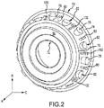
- Outer case 70 may be used in a mid-turbine frame 38, discussed above with respect to FIG. 1 , which in addition to outer case 70 includes airfoils 40 (shown in FIG. 1 ). Although described with respect to mid-turbine frame 38, stiffness bosses 102 may be used in any portion of the outer case in which rigidity control of the case is desired.
- An A-R-C axis is shown throughout the drawings to illustrate the axial, radial and circumferential (or transverse) directions.
- Outer case 70 includes outer flange 74 and inner flange 76 for connection to aft and forward case assemblies, respectively.
- Outer flange 74 has a greater diameter than inner flange 76 and inner flange 76 is located axially forward of outer flange 74, in the positive A direction. This orientation results in outer case 70 having outer case surface 120, which is between outer flange 74 and inner flange 76, sloping radially inward (in the negative R direction and the positive A direction).
- Outer case 70 further includes multiple support member bosses 78 disposed circumferentially around outer case 70 for receiving and securing support structures such as struts or rods that communicate forces radially inward in the negative R direction. Additionally, multiple spoke bosses 80 are similarly disposed circumferentially around outer case 70 that allow for attachment of parts used in various functions of the outer case 70 and gas turbine engine 2, in general.
- gusseted bosses 82 are disposed circumferentially around outer case 70, and between support member bosses 78 and/or spoke bosses 80. Gusseted bosses 82 provide system stiffness symmetry, thereby minimizing deformation of the outer case 70 and centerline shift.
- the interior of gusseted boss 82 may be hollow, which reduces the weight of outer case 70 without affecting the load bearing capability of outer case 70.
- the process of fabricating the gusseted boss 82 may be time consuming, as it may be machined on both sides in order to achieve its hollow configuration.
- Load applied at the support member bosses 78 and the spoke bosses 80 may be counteracted with reinforced, stiffened regions between the points of contact, such that the outer case 70 resists deformation.
- stiffness bosses 102 are fabricated to assist in resisting deformation of the outer case 70.
- stiffness bosses 102 may be used to reinforce rigidity of the outer case 70 and maintain the outer case 70 shape.
- the geometry of stiffness bosses 102, and the placement of stiffness bosses 102 circumferentially around outer case 70 provides additional stiffness to outer case 70 that resists or prevents deforming of outer case 70 in response to forces applied via support member bosses 78 and spoke bosses 80.
- Stiffness bosses 102 may be manufactured on one side of the outer case 70, making them less expensive to manufacture than gusseted bosses 82, which may be machined from both sides.
- Stiffness bosses 102 may also be lighter and may use fewer materials to manufacture than unused spoke bosses 80.
- gusseted bosses may be a type of stiffness boss. Gusseted bosses may provide rigidity in response to a radial load applied to the outer case 70. Gusseted bosses may also provide rigidity in response to an axial load applied to the outer case 70. Gusseted bosses may also provide rigidity in response to a transverse load applied to the outer case 70.
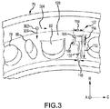
- outer case 70 includes support member boss 78, spoke boss 80, gusseted boss 82, and stiffness boss 102.
- Stiffness boss 102 includes a head portion 104 and a leg portion 106.
- the head portion 104 is flat and approximately parallel to the engine centerline axis X-X', as shown in FIGS 4 and 5 .
- the head portion 104 has a head length 116 and a head width 114.
- the leg portion 106 is also flat, but sloped downward and radially inward.
- the leg portion 106 has a leg length 112 and a leg width 110.
- Head length 116, head width 114, leg length 112, and leg width 110 may be determined such that rigidity provided by the stiffness boss 102 is optimized. Head length 116, head width 114, leg length 112, and leg width 110 may also be determined such that rigidity provided by the stiffness boss 102 is optimized and weight of the stiffness boss 102 is minimized.
- the dimensions of the head portion 104 and the leg portion 106 may be optimized using virtual modeling of the turbine case, or may be optimized based on fabricating and testing the turbine case with stiffness bosses having various head portion 104 and leg portion 106 dimensions.
- the leg portion 106 provides a primary source of rigidity in response to an axial load 302 being applied to the outer case 70 in the positive A direction.
- a transverse load 304 is applied to the outer case 70 in the positive C direction
- the head portion 104 provides a primary source of rigidity.
- a radial load 306 is applied to the outer case 70 in a negative R direction, both the head portion 104 and the leg portion 106 provide rigidity.
- the stiffness boss 102 may be made of a metal or metal alloys.
- the stiffness boss 102 is made of a nickel superalloy such as an austenitic nickel-chromium-based alloy such as that sold under the trademark Inconel® which is available from Special Metals Corporation of New Hartford, New York, USA.
- the stiffness boss 102 may be made of the same material as the outer case 70, or may be made of a different material from the outer case 70.
- the stiffness boss 102 may be welded, brazed, additively manufactured, machined, or cast on to the outer case 70 (and outer case surface 120). Also shown is filleted portion 108, which curves radially inward from the outer case surface 120 to the head portion 104 and to the leg portion 106. The filleted portion 108 may be a result of welding the head portion 104 and the leg portion 106 to the outer case 70 at outer case surface 120. The filleted portion 108 may be part of the design of the stiffness boss 102, which may be cast, additively manufactured, or machined. Filleted portion 108 may provide support for the head portion 104 and the leg portion 106. Filleted portion 108 may also surround the perimeter of the head portion 104 and the leg portion 106.
- Stiffness boss 102 provides rigidity for the outer case 70 substantially similar to the rigidity provided by a spoke boss 80 that is not used as an attachment means. As such, stiffness boss 102 may be placed anywhere spoke boss 80 is located. For example, FIG. 2 illustrates alternating between spoke boss 80 and stiffness boss 102 around the circumference of the outer case 70. However, stiffness boss 102 may be located instead of any of the spoke bosses 80, and rigidity of the outer case 70 may be maintained.
- stiffness boss 102 While the dimensions of the stiffness boss 102 may contribute to determining the amount of rigidity provided by the stiffness boss 102, the location of the stiffness boss 102 on the outer case 70 may also contribute to the rigidity. Rigidity provided by stiffness boss 102 may vary based on its relative location to spoke boss 80 and support member boss 78.
- FIG. 4 illustrates a side view of the stiffness boss 102.
- head portion 104 having head width 114, is approximately parallel to axis X-X'. Shown is head portion surface plane 202 which is approximately parallel to axis X-X'.
- outer case surface 120 is sloped radially inward (in the negative R direction and the positive A direction).
- Leg portion 106 is flat and has a leg length 112 and a leg surface length 118. Filleted portion 108 is also shown, connecting the head portion 104 and the leg portion 106 to the outer case surface 120.
- FIG. 5 illustrates a side view of the stiffness boss 102 that is opposite on circumferential axis C of the side view shown in FIG. 4 .
- head portion 104 having head width 114, is approximately parallel to axis X-X'.
- head portion surface plane 202 which is approximately parallel to axis X-X'.
- outer case surface 120 is sloped downward and in the axially forward direction.
- Leg portion 106 is flat and has a leg length 112 and a leg surface length 118.
- Filleted portion 108 is also shown, connecting the head portion 104 and the leg portion 106 to the outer case surface 120.
- the center of head portion 104 may be in a negative C direction of the center of leg portion 106. Further, while stiffness bosses 102 with the head portion 104 being radially outward relative to the leg portion 106 are shown, the head portion 104 may be radially inward relative to the leg portion 106.
- references to "one embodiment”, “an embodiment”, “an example embodiment”, etc. indicate that the embodiment described may include a particular feature, structure, or characteristic, but every embodiment may not necessarily include the particular feature, structure, or characteristic. Moreover, such phrases are not necessarily referring to the same embodiment. Further, when a particular feature, structure, or characteristic is described in connection with an embodiment, it is submitted that it is within the knowledge of one skilled in the art to affect such feature, structure, or characteristic in connection with other embodiments whether or not explicitly described. After reading the description, it will be apparent to one skilled in the relevant art(s) how to implement the disclosure in alternative embodiments.
- the terms “comprises”, “comprising”, or any other variation thereof, are intended to cover a non-exclusive inclusion, such that a process, method, article, or apparatus that comprises a list of elements does not include only those elements but may include other elements not expressly listed or inherent to such process, method, article, or apparatus.
Landscapes
- Engineering & Computer Science (AREA)
- Mechanical Engineering (AREA)
- General Engineering & Computer Science (AREA)
- Structures Of Non-Positive Displacement Pumps (AREA)
- Cylinder Crankcases Of Internal Combustion Engines (AREA)
- Turbine Rotor Nozzle Sealing (AREA)
Applications Claiming Priority (1)
| Application Number | Priority Date | Filing Date | Title |
|---|---|---|---|
| US15/188,170 US20170362960A1 (en) | 2016-06-21 | 2016-06-21 | Turbine case boss |
Publications (3)
| Publication Number | Publication Date |
|---|---|
| EP3263841A2 true EP3263841A2 (de) | 2018-01-03 |
| EP3263841A3 EP3263841A3 (de) | 2018-04-25 |
| EP3263841B1 EP3263841B1 (de) | 2021-10-13 |
Family
ID=59093466
Family Applications (1)
| Application Number | Title | Priority Date | Filing Date |
|---|---|---|---|
| EP17176961.5A Active EP3263841B1 (de) | 2016-06-21 | 2017-06-20 | Turbinengehäuseverstärkung |
Country Status (2)
| Country | Link |
|---|---|
| US (1) | US20170362960A1 (de) |
| EP (1) | EP3263841B1 (de) |
Families Citing this family (3)
| Publication number | Priority date | Publication date | Assignee | Title |
|---|---|---|---|---|
| US9416677B2 (en) * | 2012-01-10 | 2016-08-16 | United Technologies Corporation | Gas turbine engine forward bearing compartment architecture |
| US10781721B2 (en) * | 2018-02-09 | 2020-09-22 | General Electric Company | Integral turbine center frame |
| US11859506B2 (en) | 2022-05-17 | 2024-01-02 | Pratt & Whitney Canada Corp. | Mounting structure for a gas turbine engine case |
Family Cites Families (17)
| Publication number | Priority date | Publication date | Assignee | Title |
|---|---|---|---|---|
| US4418266A (en) * | 1981-10-21 | 1983-11-29 | United Technologies Corporation | Welding system for contour joints |
| US5605438A (en) * | 1995-12-29 | 1997-02-25 | General Electric Co. | Casing distortion control for rotating machinery |
| US6619917B2 (en) * | 2000-12-19 | 2003-09-16 | United Technologies Corporation | Machined fan exit guide vane attachment pockets for use in a gas turbine |
| GB2442238B (en) * | 2006-09-29 | 2008-10-01 | Rolls Royce Plc | Sheet metal blank |
| US8245518B2 (en) * | 2008-11-28 | 2012-08-21 | Pratt & Whitney Canada Corp. | Mid turbine frame system for gas turbine engine |
| US8162603B2 (en) * | 2009-01-30 | 2012-04-24 | General Electric Company | Vane frame for a turbomachine and method of minimizing weight thereof |
| US9194258B2 (en) * | 2012-02-27 | 2015-11-24 | Pratt & Whitney Canada Corp. | Gas turbine engine case bosses |
| US9316108B2 (en) * | 2012-03-05 | 2016-04-19 | General Electric Company | Gas turbine frame stiffening rails |
| US20150226125A1 (en) * | 2012-09-26 | 2015-08-13 | United Technologies Corporation | Combined high pressure turbine case and turbine intermediate case |
| US9328629B2 (en) * | 2012-09-28 | 2016-05-03 | United Technologies Corporation | Outer case with gusseted boss |
| US9376935B2 (en) * | 2012-12-18 | 2016-06-28 | Pratt & Whitney Canada Corp. | Gas turbine engine mounting ring |
| WO2014105525A1 (en) * | 2012-12-29 | 2014-07-03 | United Technologies Corporation | Multi-purpose mounting |
| EP2938844B1 (de) * | 2012-12-29 | 2017-02-08 | United Technologies Corporation | Auf einem hitzeschild basierende führungsrippen für ein turbinenabgasgehäuse |
| US10330011B2 (en) * | 2013-03-11 | 2019-06-25 | United Technologies Corporation | Bench aft sub-assembly for turbine exhaust case fairing |
| EP2971575B1 (de) * | 2013-03-13 | 2017-12-27 | United Technologies Corporation | Aussendurchmesserversteifungen in k-form einer strukturellen leitschaufel |
| US10458333B2 (en) * | 2014-02-19 | 2019-10-29 | United Technologies Corporation | Reduced stress boss geometry for a gas turbine engine |
| US20180221958A1 (en) * | 2017-02-07 | 2018-08-09 | General Electric Company | Parts and methods for producing parts using hybrid additive manufacturing techniques |
-
2016
- 2016-06-21 US US15/188,170 patent/US20170362960A1/en not_active Abandoned
-
2017
- 2017-06-20 EP EP17176961.5A patent/EP3263841B1/de active Active
Non-Patent Citations (1)
| Title |
|---|
| None |
Also Published As
| Publication number | Publication date |
|---|---|
| EP3263841A3 (de) | 2018-04-25 |
| US20170362960A1 (en) | 2017-12-21 |
| EP3263841B1 (de) | 2021-10-13 |
Similar Documents
| Publication | Publication Date | Title |
|---|---|---|
| EP3404214B1 (de) | Schaufelspitzendichtungsanordnung und gasturbinentriebwerk mit einer solchen anordnung | |
| EP2565395B1 (de) | Zugstange für einen Gasturbinenmotor | |
| US10018062B2 (en) | Axial transfer tube | |
| EP3385026B1 (de) | Tragflächenstruktur und verfahren zur herstellung | |
| EP3396251B1 (de) | Krafstoffverwirbler mit Anti-drehfunktionene | |
| WO2013126471A1 (en) | Turbine frame fairing for a gas turbine engine | |
| US20150337687A1 (en) | Split cast vane fairing | |
| US9938900B2 (en) | Ceramic matrix composite turbine exhaust case for a gas turbine engine | |
| EP3489463B1 (de) | Zusammengesetzte lüfterplattformlaschenverstärkung | |
| EP3263841B1 (de) | Turbinengehäuseverstärkung | |
| EP3246517A1 (de) | Befestigungselementöffnungen zur spannungsverteilung | |
| EP3260739B1 (de) | Kostengünstiger planetengetriebeträger und verfahren zur herstellung davon | |
| US20140010649A1 (en) | Mid-turbine frame hpt seal support meshing | |
| EP3081748B1 (de) | Gasturbinenmotorsystem mit einem dichtungsring | |
| EP3553278B1 (de) | Axiale versteifungsrippen/verstärkungsrippen | |
| EP3543479A1 (de) | Flexible lagerträgeranordnung | |
| EP3081761B1 (de) | Turbinenzwischengehäuse und gasturbine mit einem turbinenzwischengehäuse | |
| EP3189922B1 (de) | Erweiterte lötverbindung für rohr-zu-rohr-verbindung | |
| EP3412868A1 (de) | Plattformkühlung mit einstellbarer durchflussteilung für einen gasturbinenmotor | |
| EP3517733B1 (de) | Gasturbinentriebwerk mit einem ringförmigen halteband und zugehöriges montageverfahren | |
| US9926789B2 (en) | Flow splitting baffle | |
| EP3249176B1 (de) | Schmutzabschirmung | |
| US10385717B2 (en) | Multi-ply seal | |
| EP3418618A1 (de) | Fitting mit mittlerem gewinde | |
| US10408088B2 (en) | Mid-turbine frame stator with repairable bushing and retention pin |
Legal Events
| Date | Code | Title | Description |
|---|---|---|---|
| PUAI | Public reference made under article 153(3) epc to a published international application that has entered the european phase |
Free format text: ORIGINAL CODE: 0009012 |
|
| STAA | Information on the status of an ep patent application or granted ep patent |
Free format text: STATUS: THE APPLICATION HAS BEEN PUBLISHED |
|
| AK | Designated contracting states |
Kind code of ref document: A2 Designated state(s): AL AT BE BG CH CY CZ DE DK EE ES FI FR GB GR HR HU IE IS IT LI LT LU LV MC MK MT NL NO PL PT RO RS SE SI SK SM TR |
|
| AX | Request for extension of the european patent |
Extension state: BA ME |
|
| PUAL | Search report despatched |
Free format text: ORIGINAL CODE: 0009013 |
|
| AK | Designated contracting states |
Kind code of ref document: A3 Designated state(s): AL AT BE BG CH CY CZ DE DK EE ES FI FR GB GR HR HU IE IS IT LI LT LU LV MC MK MT NL NO PL PT RO RS SE SI SK SM TR |
|
| AX | Request for extension of the european patent |
Extension state: BA ME |
|
| RIC1 | Information provided on ipc code assigned before grant |
Ipc: F01D 25/24 20060101ALI20180320BHEP Ipc: F01D 9/04 20060101AFI20180320BHEP |
|
| STAA | Information on the status of an ep patent application or granted ep patent |
Free format text: STATUS: REQUEST FOR EXAMINATION WAS MADE |
|
| 17P | Request for examination filed |
Effective date: 20181022 |
|
| RBV | Designated contracting states (corrected) |
Designated state(s): AL AT BE BG CH CY CZ DE DK EE ES FI FR GB GR HR HU IE IS IT LI LT LU LV MC MK MT NL NO PL PT RO RS SE SI SK SM TR |
|
| STAA | Information on the status of an ep patent application or granted ep patent |
Free format text: STATUS: EXAMINATION IS IN PROGRESS |
|
| 17Q | First examination report despatched |
Effective date: 20190812 |
|
| RAP1 | Party data changed (applicant data changed or rights of an application transferred) |
Owner name: RAYTHEON TECHNOLOGIES CORPORATION |
|
| GRAP | Despatch of communication of intention to grant a patent |
Free format text: ORIGINAL CODE: EPIDOSNIGR1 |
|
| STAA | Information on the status of an ep patent application or granted ep patent |
Free format text: STATUS: GRANT OF PATENT IS INTENDED |
|
| INTG | Intention to grant announced |
Effective date: 20210604 |
|
| GRAS | Grant fee paid |
Free format text: ORIGINAL CODE: EPIDOSNIGR3 |
|
| GRAA | (expected) grant |
Free format text: ORIGINAL CODE: 0009210 |
|
| STAA | Information on the status of an ep patent application or granted ep patent |
Free format text: STATUS: THE PATENT HAS BEEN GRANTED |
|
| AK | Designated contracting states |
Kind code of ref document: B1 Designated state(s): AL AT BE BG CH CY CZ DE DK EE ES FI FR GB GR HR HU IE IS IT LI LT LU LV MC MK MT NL NO PL PT RO RS SE SI SK SM TR |
|
| REG | Reference to a national code |
Ref country code: GB Ref legal event code: FG4D |
|
| REG | Reference to a national code |
Ref country code: CH Ref legal event code: EP |
|
| REG | Reference to a national code |
Ref country code: DE Ref legal event code: R096 Ref document number: 602017047463 Country of ref document: DE |
|
| REG | Reference to a national code |
Ref country code: IE Ref legal event code: FG4D |
|
| REG | Reference to a national code |
Ref country code: AT Ref legal event code: REF Ref document number: 1438341 Country of ref document: AT Kind code of ref document: T Effective date: 20211115 |
|
| REG | Reference to a national code |
Ref country code: LT Ref legal event code: MG9D |
|
| REG | Reference to a national code |
Ref country code: NL Ref legal event code: MP Effective date: 20211013 |
|
| REG | Reference to a national code |
Ref country code: AT Ref legal event code: MK05 Ref document number: 1438341 Country of ref document: AT Kind code of ref document: T Effective date: 20211013 |
|
| PG25 | Lapsed in a contracting state [announced via postgrant information from national office to epo] |
Ref country code: RS Free format text: LAPSE BECAUSE OF FAILURE TO SUBMIT A TRANSLATION OF THE DESCRIPTION OR TO PAY THE FEE WITHIN THE PRESCRIBED TIME-LIMIT Effective date: 20211013 Ref country code: LT Free format text: LAPSE BECAUSE OF FAILURE TO SUBMIT A TRANSLATION OF THE DESCRIPTION OR TO PAY THE FEE WITHIN THE PRESCRIBED TIME-LIMIT Effective date: 20211013 Ref country code: FI Free format text: LAPSE BECAUSE OF FAILURE TO SUBMIT A TRANSLATION OF THE DESCRIPTION OR TO PAY THE FEE WITHIN THE PRESCRIBED TIME-LIMIT Effective date: 20211013 Ref country code: BG Free format text: LAPSE BECAUSE OF FAILURE TO SUBMIT A TRANSLATION OF THE DESCRIPTION OR TO PAY THE FEE WITHIN THE PRESCRIBED TIME-LIMIT Effective date: 20220113 Ref country code: AT Free format text: LAPSE BECAUSE OF FAILURE TO SUBMIT A TRANSLATION OF THE DESCRIPTION OR TO PAY THE FEE WITHIN THE PRESCRIBED TIME-LIMIT Effective date: 20211013 |
|
| PG25 | Lapsed in a contracting state [announced via postgrant information from national office to epo] |
Ref country code: IS Free format text: LAPSE BECAUSE OF FAILURE TO SUBMIT A TRANSLATION OF THE DESCRIPTION OR TO PAY THE FEE WITHIN THE PRESCRIBED TIME-LIMIT Effective date: 20220213 Ref country code: SE Free format text: LAPSE BECAUSE OF FAILURE TO SUBMIT A TRANSLATION OF THE DESCRIPTION OR TO PAY THE FEE WITHIN THE PRESCRIBED TIME-LIMIT Effective date: 20211013 Ref country code: PT Free format text: LAPSE BECAUSE OF FAILURE TO SUBMIT A TRANSLATION OF THE DESCRIPTION OR TO PAY THE FEE WITHIN THE PRESCRIBED TIME-LIMIT Effective date: 20220214 Ref country code: PL Free format text: LAPSE BECAUSE OF FAILURE TO SUBMIT A TRANSLATION OF THE DESCRIPTION OR TO PAY THE FEE WITHIN THE PRESCRIBED TIME-LIMIT Effective date: 20211013 Ref country code: NO Free format text: LAPSE BECAUSE OF FAILURE TO SUBMIT A TRANSLATION OF THE DESCRIPTION OR TO PAY THE FEE WITHIN THE PRESCRIBED TIME-LIMIT Effective date: 20220113 Ref country code: NL Free format text: LAPSE BECAUSE OF FAILURE TO SUBMIT A TRANSLATION OF THE DESCRIPTION OR TO PAY THE FEE WITHIN THE PRESCRIBED TIME-LIMIT Effective date: 20211013 Ref country code: LV Free format text: LAPSE BECAUSE OF FAILURE TO SUBMIT A TRANSLATION OF THE DESCRIPTION OR TO PAY THE FEE WITHIN THE PRESCRIBED TIME-LIMIT Effective date: 20211013 Ref country code: HR Free format text: LAPSE BECAUSE OF FAILURE TO SUBMIT A TRANSLATION OF THE DESCRIPTION OR TO PAY THE FEE WITHIN THE PRESCRIBED TIME-LIMIT Effective date: 20211013 Ref country code: GR Free format text: LAPSE BECAUSE OF FAILURE TO SUBMIT A TRANSLATION OF THE DESCRIPTION OR TO PAY THE FEE WITHIN THE PRESCRIBED TIME-LIMIT Effective date: 20220114 Ref country code: ES Free format text: LAPSE BECAUSE OF FAILURE TO SUBMIT A TRANSLATION OF THE DESCRIPTION OR TO PAY THE FEE WITHIN THE PRESCRIBED TIME-LIMIT Effective date: 20211013 |
|
| REG | Reference to a national code |
Ref country code: DE Ref legal event code: R097 Ref document number: 602017047463 Country of ref document: DE |
|
| PG25 | Lapsed in a contracting state [announced via postgrant information from national office to epo] |
Ref country code: SM Free format text: LAPSE BECAUSE OF FAILURE TO SUBMIT A TRANSLATION OF THE DESCRIPTION OR TO PAY THE FEE WITHIN THE PRESCRIBED TIME-LIMIT Effective date: 20211013 Ref country code: SK Free format text: LAPSE BECAUSE OF FAILURE TO SUBMIT A TRANSLATION OF THE DESCRIPTION OR TO PAY THE FEE WITHIN THE PRESCRIBED TIME-LIMIT Effective date: 20211013 Ref country code: RO Free format text: LAPSE BECAUSE OF FAILURE TO SUBMIT A TRANSLATION OF THE DESCRIPTION OR TO PAY THE FEE WITHIN THE PRESCRIBED TIME-LIMIT Effective date: 20211013 Ref country code: EE Free format text: LAPSE BECAUSE OF FAILURE TO SUBMIT A TRANSLATION OF THE DESCRIPTION OR TO PAY THE FEE WITHIN THE PRESCRIBED TIME-LIMIT Effective date: 20211013 Ref country code: DK Free format text: LAPSE BECAUSE OF FAILURE TO SUBMIT A TRANSLATION OF THE DESCRIPTION OR TO PAY THE FEE WITHIN THE PRESCRIBED TIME-LIMIT Effective date: 20211013 Ref country code: CZ Free format text: LAPSE BECAUSE OF FAILURE TO SUBMIT A TRANSLATION OF THE DESCRIPTION OR TO PAY THE FEE WITHIN THE PRESCRIBED TIME-LIMIT Effective date: 20211013 |
|
| PLBE | No opposition filed within time limit |
Free format text: ORIGINAL CODE: 0009261 |
|
| STAA | Information on the status of an ep patent application or granted ep patent |
Free format text: STATUS: NO OPPOSITION FILED WITHIN TIME LIMIT |
|
| 26N | No opposition filed |
Effective date: 20220714 |
|
| PG25 | Lapsed in a contracting state [announced via postgrant information from national office to epo] |
Ref country code: AL Free format text: LAPSE BECAUSE OF FAILURE TO SUBMIT A TRANSLATION OF THE DESCRIPTION OR TO PAY THE FEE WITHIN THE PRESCRIBED TIME-LIMIT Effective date: 20211013 |
|
| PG25 | Lapsed in a contracting state [announced via postgrant information from national office to epo] |
Ref country code: SI Free format text: LAPSE BECAUSE OF FAILURE TO SUBMIT A TRANSLATION OF THE DESCRIPTION OR TO PAY THE FEE WITHIN THE PRESCRIBED TIME-LIMIT Effective date: 20211013 |
|
| PG25 | Lapsed in a contracting state [announced via postgrant information from national office to epo] |
Ref country code: MC Free format text: LAPSE BECAUSE OF FAILURE TO SUBMIT A TRANSLATION OF THE DESCRIPTION OR TO PAY THE FEE WITHIN THE PRESCRIBED TIME-LIMIT Effective date: 20211013 |
|
| REG | Reference to a national code |
Ref country code: CH Ref legal event code: PL |
|
| REG | Reference to a national code |
Ref country code: BE Ref legal event code: MM Effective date: 20220630 |
|
| PG25 | Lapsed in a contracting state [announced via postgrant information from national office to epo] |
Ref country code: LU Free format text: LAPSE BECAUSE OF NON-PAYMENT OF DUE FEES Effective date: 20220620 Ref country code: LI Free format text: LAPSE BECAUSE OF NON-PAYMENT OF DUE FEES Effective date: 20220630 Ref country code: IE Free format text: LAPSE BECAUSE OF NON-PAYMENT OF DUE FEES Effective date: 20220620 Ref country code: CH Free format text: LAPSE BECAUSE OF NON-PAYMENT OF DUE FEES Effective date: 20220630 |
|
| PG25 | Lapsed in a contracting state [announced via postgrant information from national office to epo] |
Ref country code: IT Free format text: LAPSE BECAUSE OF FAILURE TO SUBMIT A TRANSLATION OF THE DESCRIPTION OR TO PAY THE FEE WITHIN THE PRESCRIBED TIME-LIMIT Effective date: 20211013 Ref country code: BE Free format text: LAPSE BECAUSE OF NON-PAYMENT OF DUE FEES Effective date: 20220630 |
|
| P01 | Opt-out of the competence of the unified patent court (upc) registered |
Effective date: 20230520 |
|
| PG25 | Lapsed in a contracting state [announced via postgrant information from national office to epo] |
Ref country code: HU Free format text: LAPSE BECAUSE OF FAILURE TO SUBMIT A TRANSLATION OF THE DESCRIPTION OR TO PAY THE FEE WITHIN THE PRESCRIBED TIME-LIMIT; INVALID AB INITIO Effective date: 20170620 |
|
| PG25 | Lapsed in a contracting state [announced via postgrant information from national office to epo] |
Ref country code: MK Free format text: LAPSE BECAUSE OF FAILURE TO SUBMIT A TRANSLATION OF THE DESCRIPTION OR TO PAY THE FEE WITHIN THE PRESCRIBED TIME-LIMIT Effective date: 20211013 Ref country code: CY Free format text: LAPSE BECAUSE OF FAILURE TO SUBMIT A TRANSLATION OF THE DESCRIPTION OR TO PAY THE FEE WITHIN THE PRESCRIBED TIME-LIMIT Effective date: 20211013 |
|
| PG25 | Lapsed in a contracting state [announced via postgrant information from national office to epo] |
Ref country code: MT Free format text: LAPSE BECAUSE OF FAILURE TO SUBMIT A TRANSLATION OF THE DESCRIPTION OR TO PAY THE FEE WITHIN THE PRESCRIBED TIME-LIMIT Effective date: 20211013 |
|
| PGFP | Annual fee paid to national office [announced via postgrant information from national office to epo] |
Ref country code: DE Payment date: 20250520 Year of fee payment: 9 |
|
| PGFP | Annual fee paid to national office [announced via postgrant information from national office to epo] |
Ref country code: GB Payment date: 20250520 Year of fee payment: 9 |
|
| PGFP | Annual fee paid to national office [announced via postgrant information from national office to epo] |
Ref country code: FR Payment date: 20250520 Year of fee payment: 9 |
|
| REG | Reference to a national code |
Ref country code: DE Ref legal event code: R081 Ref document number: 602017047463 Country of ref document: DE Owner name: RTX CORPORATION (N.D.GES.D. STAATES DELAWARE),, US Free format text: FORMER OWNER: RAYTHEON TECHNOLOGIES CORPORATION, FARMINGTON, CT, US |
|
| PG25 | Lapsed in a contracting state [announced via postgrant information from national office to epo] |
Ref country code: TR Free format text: LAPSE BECAUSE OF FAILURE TO SUBMIT A TRANSLATION OF THE DESCRIPTION OR TO PAY THE FEE WITHIN THE PRESCRIBED TIME-LIMIT Effective date: 20211013 |