EP3263522A1 - High-density carbon nanotube aggregate and method of producing high-density carbon nanotube aggregate - Google Patents
High-density carbon nanotube aggregate and method of producing high-density carbon nanotube aggregate Download PDFInfo
- Publication number
- EP3263522A1 EP3263522A1 EP16755569.7A EP16755569A EP3263522A1 EP 3263522 A1 EP3263522 A1 EP 3263522A1 EP 16755569 A EP16755569 A EP 16755569A EP 3263522 A1 EP3263522 A1 EP 3263522A1
- Authority
- EP
- European Patent Office
- Prior art keywords
- carbon nanotube
- density
- aggregate
- nanotube array
- nanotube aggregate
- Prior art date
- Legal status (The legal status is an assumption and is not a legal conclusion. Google has not performed a legal analysis and makes no representation as to the accuracy of the status listed.)
- Withdrawn
Links
- OKTJSMMVPCPJKN-UHFFFAOYSA-N Carbon Chemical compound [C] OKTJSMMVPCPJKN-UHFFFAOYSA-N 0.000 title claims abstract description 590
- 239000002041 carbon nanotube Substances 0.000 title claims abstract description 558
- 229910021393 carbon nanotube Inorganic materials 0.000 title claims abstract description 558
- 238000000034 method Methods 0.000 title claims abstract description 50
- 238000010438 heat treatment Methods 0.000 claims abstract description 120
- 239000000758 substrate Substances 0.000 claims abstract description 78
- 239000007788 liquid Substances 0.000 claims description 41
- 238000001816 cooling Methods 0.000 claims description 30
- 230000000052 comparative effect Effects 0.000 description 31
- 229910052799 carbon Inorganic materials 0.000 description 25
- 239000007789 gas Substances 0.000 description 24
- VYPSYNLAJGMNEJ-UHFFFAOYSA-N Silicium dioxide Chemical compound O=[Si]=O VYPSYNLAJGMNEJ-UHFFFAOYSA-N 0.000 description 20
- 230000002093 peripheral effect Effects 0.000 description 16
- 239000003054 catalyst Substances 0.000 description 13
- 238000003491 array Methods 0.000 description 11
- 235000012239 silicon dioxide Nutrition 0.000 description 10
- 239000000377 silicon dioxide Substances 0.000 description 10
- XLYOFNOQVPJJNP-UHFFFAOYSA-N water Substances O XLYOFNOQVPJJNP-UHFFFAOYSA-N 0.000 description 9
- 239000012300 argon atmosphere Substances 0.000 description 8
- 229910021389 graphene Inorganic materials 0.000 description 8
- XKRFYHLGVUSROY-UHFFFAOYSA-N Argon Chemical compound [Ar] XKRFYHLGVUSROY-UHFFFAOYSA-N 0.000 description 6
- XEEYBQQBJWHFJM-UHFFFAOYSA-N Iron Chemical compound [Fe] XEEYBQQBJWHFJM-UHFFFAOYSA-N 0.000 description 6
- 238000001237 Raman spectrum Methods 0.000 description 6
- 239000008187 granular material Substances 0.000 description 6
- 239000011261 inert gas Substances 0.000 description 6
- 229910001220 stainless steel Inorganic materials 0.000 description 6
- 239000010935 stainless steel Substances 0.000 description 6
- 238000004220 aggregation Methods 0.000 description 5
- 230000002776 aggregation Effects 0.000 description 5
- 238000005520 cutting process Methods 0.000 description 5
- 229930195733 hydrocarbon Natural products 0.000 description 5
- 238000005259 measurement Methods 0.000 description 5
- 239000004215 Carbon black (E152) Substances 0.000 description 4
- 230000006835 compression Effects 0.000 description 4
- 238000007906 compression Methods 0.000 description 4
- -1 etc.) Chemical compound 0.000 description 4
- 150000002430 hydrocarbons Chemical class 0.000 description 4
- 238000004519 manufacturing process Methods 0.000 description 4
- 239000002184 metal Substances 0.000 description 4
- 229910052751 metal Inorganic materials 0.000 description 4
- UHOVQNZJYSORNB-UHFFFAOYSA-N Benzene Chemical compound C1=CC=CC=C1 UHOVQNZJYSORNB-UHFFFAOYSA-N 0.000 description 3
- YMWUJEATGCHHMB-UHFFFAOYSA-N Dichloromethane Chemical compound ClCCl YMWUJEATGCHHMB-UHFFFAOYSA-N 0.000 description 3
- RTZKZFJDLAIYFH-UHFFFAOYSA-N Diethyl ether Chemical compound CCOCC RTZKZFJDLAIYFH-UHFFFAOYSA-N 0.000 description 3
- XEKOWRVHYACXOJ-UHFFFAOYSA-N Ethyl acetate Chemical compound CCOC(C)=O XEKOWRVHYACXOJ-UHFFFAOYSA-N 0.000 description 3
- OKKJLVBELUTLKV-UHFFFAOYSA-N Methanol Chemical compound OC OKKJLVBELUTLKV-UHFFFAOYSA-N 0.000 description 3
- ZMXDDKWLCZADIW-UHFFFAOYSA-N N,N-Dimethylformamide Chemical compound CN(C)C=O ZMXDDKWLCZADIW-UHFFFAOYSA-N 0.000 description 3
- YXFVVABEGXRONW-UHFFFAOYSA-N Toluene Chemical compound CC1=CC=CC=C1 YXFVVABEGXRONW-UHFFFAOYSA-N 0.000 description 3
- 238000005411 Van der Waals force Methods 0.000 description 3
- 150000001338 aliphatic hydrocarbons Chemical class 0.000 description 3
- HSFWRNGVRCDJHI-UHFFFAOYSA-N alpha-acetylene Natural products C#C HSFWRNGVRCDJHI-UHFFFAOYSA-N 0.000 description 3
- 229910052786 argon Inorganic materials 0.000 description 3
- 238000005229 chemical vapour deposition Methods 0.000 description 3
- 125000002534 ethynyl group Chemical group [H]C#C* 0.000 description 3
- 229910052742 iron Inorganic materials 0.000 description 3
- VLKZOEOYAKHREP-UHFFFAOYSA-N n-Hexane Chemical compound CCCCCC VLKZOEOYAKHREP-UHFFFAOYSA-N 0.000 description 3
- 230000003595 spectral effect Effects 0.000 description 3
- CSCPPACGZOOCGX-UHFFFAOYSA-N Acetone Chemical compound CC(C)=O CSCPPACGZOOCGX-UHFFFAOYSA-N 0.000 description 2
- IJGRMHOSHXDMSA-UHFFFAOYSA-N Atomic nitrogen Chemical compound N#N IJGRMHOSHXDMSA-UHFFFAOYSA-N 0.000 description 2
- HEDRZPFGACZZDS-UHFFFAOYSA-N Chloroform Chemical compound ClC(Cl)Cl HEDRZPFGACZZDS-UHFFFAOYSA-N 0.000 description 2
- LFQSCWFLJHTTHZ-UHFFFAOYSA-N Ethanol Chemical compound CCO LFQSCWFLJHTTHZ-UHFFFAOYSA-N 0.000 description 2
- UFHFLCQGNIYNRP-UHFFFAOYSA-N Hydrogen Chemical compound [H][H] UFHFLCQGNIYNRP-UHFFFAOYSA-N 0.000 description 2
- IMNFDUFMRHMDMM-UHFFFAOYSA-N N-Heptane Chemical compound CCCCCCC IMNFDUFMRHMDMM-UHFFFAOYSA-N 0.000 description 2
- PXHVJJICTQNCMI-UHFFFAOYSA-N Nickel Chemical compound [Ni] PXHVJJICTQNCMI-UHFFFAOYSA-N 0.000 description 2
- ATUOYWHBWRKTHZ-UHFFFAOYSA-N Propane Chemical compound CCC ATUOYWHBWRKTHZ-UHFFFAOYSA-N 0.000 description 2
- WYURNTSHIVDZCO-UHFFFAOYSA-N Tetrahydrofuran Chemical compound C1CCOC1 WYURNTSHIVDZCO-UHFFFAOYSA-N 0.000 description 2
- 150000001298 alcohols Chemical class 0.000 description 2
- 230000015572 biosynthetic process Effects 0.000 description 2
- 239000000919 ceramic Substances 0.000 description 2
- 238000013329 compounding Methods 0.000 description 2
- 238000004090 dissolution Methods 0.000 description 2
- VNWKTOKETHGBQD-UHFFFAOYSA-N methane Chemical compound C VNWKTOKETHGBQD-UHFFFAOYSA-N 0.000 description 2
- UAEPNZWRGJTJPN-UHFFFAOYSA-N methylcyclohexane Chemical compound CC1CCCCC1 UAEPNZWRGJTJPN-UHFFFAOYSA-N 0.000 description 2
- 239000000203 mixture Substances 0.000 description 2
- 239000002048 multi walled nanotube Substances 0.000 description 2
- 239000003960 organic solvent Substances 0.000 description 2
- 230000000704 physical effect Effects 0.000 description 2
- 238000001228 spectrum Methods 0.000 description 2
- 238000000859 sublimation Methods 0.000 description 2
- 230000008022 sublimation Effects 0.000 description 2
- 238000001771 vacuum deposition Methods 0.000 description 2
- HMUNWXXNJPVALC-UHFFFAOYSA-N 1-[4-[2-(2,3-dihydro-1H-inden-2-ylamino)pyrimidin-5-yl]piperazin-1-yl]-2-(2,4,6,7-tetrahydrotriazolo[4,5-c]pyridin-5-yl)ethanone Chemical compound C1C(CC2=CC=CC=C12)NC1=NC=C(C=N1)N1CCN(CC1)C(CN1CC2=C(CC1)NN=N2)=O HMUNWXXNJPVALC-UHFFFAOYSA-N 0.000 description 1
- YJLUBHOZZTYQIP-UHFFFAOYSA-N 2-[5-[2-(2,3-dihydro-1H-inden-2-ylamino)pyrimidin-5-yl]-1,3,4-oxadiazol-2-yl]-1-(2,4,6,7-tetrahydrotriazolo[4,5-c]pyridin-5-yl)ethanone Chemical compound C1C(CC2=CC=CC=C12)NC1=NC=C(C=N1)C1=NN=C(O1)CC(=O)N1CC2=C(CC1)NN=N2 YJLUBHOZZTYQIP-UHFFFAOYSA-N 0.000 description 1
- XDTMQSROBMDMFD-UHFFFAOYSA-N Cyclohexane Chemical compound C1CCCCC1 XDTMQSROBMDMFD-UHFFFAOYSA-N 0.000 description 1
- OTMSDBZUPAUEDD-UHFFFAOYSA-N Ethane Chemical compound CC OTMSDBZUPAUEDD-UHFFFAOYSA-N 0.000 description 1
- VGGSQFUCUMXWEO-UHFFFAOYSA-N Ethene Chemical compound C=C VGGSQFUCUMXWEO-UHFFFAOYSA-N 0.000 description 1
- 239000005977 Ethylene Substances 0.000 description 1
- SECXISVLQFMRJM-UHFFFAOYSA-N N-Methylpyrrolidone Chemical compound CN1CCCC1=O SECXISVLQFMRJM-UHFFFAOYSA-N 0.000 description 1
- 238000001069 Raman spectroscopy Methods 0.000 description 1
- XUIMIQQOPSSXEZ-UHFFFAOYSA-N Silicon Chemical compound [Si] XUIMIQQOPSSXEZ-UHFFFAOYSA-N 0.000 description 1
- 125000005907 alkyl ester group Chemical group 0.000 description 1
- 150000004945 aromatic hydrocarbons Chemical class 0.000 description 1
- 239000012298 atmosphere Substances 0.000 description 1
- 239000001273 butane Substances 0.000 description 1
- 238000004364 calculation method Methods 0.000 description 1
- 229910017052 cobalt Inorganic materials 0.000 description 1
- 239000010941 cobalt Substances 0.000 description 1
- GUTLYIVDDKVIGB-UHFFFAOYSA-N cobalt atom Chemical compound [Co] GUTLYIVDDKVIGB-UHFFFAOYSA-N 0.000 description 1
- 150000001875 compounds Chemical class 0.000 description 1
- 230000007547 defect Effects 0.000 description 1
- 239000002079 double walled nanotube Substances 0.000 description 1
- 238000001035 drying Methods 0.000 description 1
- 150000002170 ethers Chemical class 0.000 description 1
- 238000011156 evaluation Methods 0.000 description 1
- 238000001704 evaporation Methods 0.000 description 1
- 230000008020 evaporation Effects 0.000 description 1
- 239000001307 helium Substances 0.000 description 1
- 229910052734 helium Inorganic materials 0.000 description 1
- SWQJXJOGLNCZEY-UHFFFAOYSA-N helium atom Chemical compound [He] SWQJXJOGLNCZEY-UHFFFAOYSA-N 0.000 description 1
- 230000006698 induction Effects 0.000 description 1
- 150000002576 ketones Chemical class 0.000 description 1
- 239000012685 metal catalyst precursor Substances 0.000 description 1
- GYNNXHKOJHMOHS-UHFFFAOYSA-N methyl-cycloheptane Natural products CC1CCCCCC1 GYNNXHKOJHMOHS-UHFFFAOYSA-N 0.000 description 1
- 238000001000 micrograph Methods 0.000 description 1
- IJDNQMDRQITEOD-UHFFFAOYSA-N n-butane Chemical compound CCCC IJDNQMDRQITEOD-UHFFFAOYSA-N 0.000 description 1
- OFBQJSOFQDEBGM-UHFFFAOYSA-N n-pentane Natural products CCCCC OFBQJSOFQDEBGM-UHFFFAOYSA-N 0.000 description 1
- 229910052759 nickel Inorganic materials 0.000 description 1
- 229910052757 nitrogen Inorganic materials 0.000 description 1
- TVMXDCGIABBOFY-UHFFFAOYSA-N octane Chemical compound CCCCCCCC TVMXDCGIABBOFY-UHFFFAOYSA-N 0.000 description 1
- 239000002243 precursor Substances 0.000 description 1
- BDERNNFJNOPAEC-UHFFFAOYSA-N propan-1-ol Chemical compound CCCO BDERNNFJNOPAEC-UHFFFAOYSA-N 0.000 description 1
- 239000001294 propane Substances 0.000 description 1
- 238000010926 purge Methods 0.000 description 1
- 239000002994 raw material Substances 0.000 description 1
- 238000000926 separation method Methods 0.000 description 1
- 229910052710 silicon Inorganic materials 0.000 description 1
- 239000010703 silicon Substances 0.000 description 1
- 239000002109 single walled nanotube Substances 0.000 description 1
- 238000005507 spraying Methods 0.000 description 1
- 238000004544 sputter deposition Methods 0.000 description 1
- YLQBMQCUIZJEEH-UHFFFAOYSA-N tetrahydrofuran Natural products C=1C=COC=1 YLQBMQCUIZJEEH-UHFFFAOYSA-N 0.000 description 1
Images





Classifications
-
- C—CHEMISTRY; METALLURGY
- C01—INORGANIC CHEMISTRY
- C01B—NON-METALLIC ELEMENTS; COMPOUNDS THEREOF; METALLOIDS OR COMPOUNDS THEREOF NOT COVERED BY SUBCLASS C01C
- C01B32/00—Carbon; Compounds thereof
- C01B32/15—Nano-sized carbon materials
- C01B32/158—Carbon nanotubes
- C01B32/168—After-treatment
-
- C—CHEMISTRY; METALLURGY
- C01—INORGANIC CHEMISTRY
- C01B—NON-METALLIC ELEMENTS; COMPOUNDS THEREOF; METALLOIDS OR COMPOUNDS THEREOF NOT COVERED BY SUBCLASS C01C
- C01B32/00—Carbon; Compounds thereof
- C01B32/05—Preparation or purification of carbon not covered by groups C01B32/15, C01B32/20, C01B32/25, C01B32/30
-
- B—PERFORMING OPERATIONS; TRANSPORTING
- B01—PHYSICAL OR CHEMICAL PROCESSES OR APPARATUS IN GENERAL
- B01J—CHEMICAL OR PHYSICAL PROCESSES, e.g. CATALYSIS OR COLLOID CHEMISTRY; THEIR RELEVANT APPARATUS
- B01J20/00—Solid sorbent compositions or filter aid compositions; Sorbents for chromatography; Processes for preparing, regenerating or reactivating thereof
- B01J20/02—Solid sorbent compositions or filter aid compositions; Sorbents for chromatography; Processes for preparing, regenerating or reactivating thereof comprising inorganic material
- B01J20/20—Solid sorbent compositions or filter aid compositions; Sorbents for chromatography; Processes for preparing, regenerating or reactivating thereof comprising inorganic material comprising free carbon; comprising carbon obtained by carbonising processes
- B01J20/205—Carbon nanostructures, e.g. nanotubes, nanohorns, nanocones, nanoballs
-
- B—PERFORMING OPERATIONS; TRANSPORTING
- B82—NANOTECHNOLOGY
- B82Y—SPECIFIC USES OR APPLICATIONS OF NANOSTRUCTURES; MEASUREMENT OR ANALYSIS OF NANOSTRUCTURES; MANUFACTURE OR TREATMENT OF NANOSTRUCTURES
- B82Y40/00—Manufacture or treatment of nanostructures
-
- C—CHEMISTRY; METALLURGY
- C01—INORGANIC CHEMISTRY
- C01B—NON-METALLIC ELEMENTS; COMPOUNDS THEREOF; METALLOIDS OR COMPOUNDS THEREOF NOT COVERED BY SUBCLASS C01C
- C01B32/00—Carbon; Compounds thereof
- C01B32/15—Nano-sized carbon materials
- C01B32/158—Carbon nanotubes
- C01B32/16—Preparation
- C01B32/162—Preparation characterised by catalysts
-
- C—CHEMISTRY; METALLURGY
- C01—INORGANIC CHEMISTRY
- C01B—NON-METALLIC ELEMENTS; COMPOUNDS THEREOF; METALLOIDS OR COMPOUNDS THEREOF NOT COVERED BY SUBCLASS C01C
- C01B32/00—Carbon; Compounds thereof
- C01B32/15—Nano-sized carbon materials
- C01B32/158—Carbon nanotubes
- C01B32/168—After-treatment
- C01B32/17—Purification
-
- C—CHEMISTRY; METALLURGY
- C01—INORGANIC CHEMISTRY
- C01B—NON-METALLIC ELEMENTS; COMPOUNDS THEREOF; METALLOIDS OR COMPOUNDS THEREOF NOT COVERED BY SUBCLASS C01C
- C01B32/00—Carbon; Compounds thereof
- C01B32/20—Graphite
- C01B32/21—After-treatment
-
- B—PERFORMING OPERATIONS; TRANSPORTING
- B82—NANOTECHNOLOGY
- B82Y—SPECIFIC USES OR APPLICATIONS OF NANOSTRUCTURES; MEASUREMENT OR ANALYSIS OF NANOSTRUCTURES; MANUFACTURE OR TREATMENT OF NANOSTRUCTURES
- B82Y30/00—Nanotechnology for materials or surface science, e.g. nanocomposites
-
- C—CHEMISTRY; METALLURGY
- C01—INORGANIC CHEMISTRY
- C01B—NON-METALLIC ELEMENTS; COMPOUNDS THEREOF; METALLOIDS OR COMPOUNDS THEREOF NOT COVERED BY SUBCLASS C01C
- C01B2202/00—Structure or properties of carbon nanotubes
- C01B2202/08—Aligned nanotubes
-
- C—CHEMISTRY; METALLURGY
- C01—INORGANIC CHEMISTRY
- C01B—NON-METALLIC ELEMENTS; COMPOUNDS THEREOF; METALLOIDS OR COMPOUNDS THEREOF NOT COVERED BY SUBCLASS C01C
- C01B2202/00—Structure or properties of carbon nanotubes
- C01B2202/20—Nanotubes characterized by their properties
- C01B2202/26—Mechanical properties
-
- C—CHEMISTRY; METALLURGY
- C01—INORGANIC CHEMISTRY
- C01P—INDEXING SCHEME RELATING TO STRUCTURAL AND PHYSICAL ASPECTS OF SOLID INORGANIC COMPOUNDS
- C01P2004/00—Particle morphology
- C01P2004/60—Particles characterised by their size
- C01P2004/64—Nanometer sized, i.e. from 1-100 nanometer
Definitions
- the present invention relates to a high-density carbon nanotube aggregate and a method of producing the high-density carbon nanotube aggregate.
- a carbon nanotube is known to have an excellent mechanical strength, thermal conductivity, and electric conductivity. It has been studied to grow a plurality of carbon nanotubes to make a carbon nanotube array and use such carbon nanotube arrays in various industrial products.
- a method of producing an oriented carbon nanotube bulk aggregate in which the chemical vapor deposition is used to grow a plurality of carbon nanotubes on a substrate so as to be oriented vertically to the substrate surface, then the plurality of carbon nanotubes are separated from the substrate, the plurality of separated carbon nanotubes are exposed to a liquid such as water and then dried (see, e.g., Patent Document 1).
- Patent Document 1 Japanese Patent Application Publication No. 2007-182352
- the orientation of the plurality of carbon nanotubes may be disordered when the plurality of carbon nanotubes are exposed to the liquid, and thus, it is difficult to maintain the orientation of the plurality of carbon nanotubes in the oriented carbon nanotube bulk aggregate.
- One object of the present invention is to provide a high-density carbon nanotube aggregate and a method of producing the high-density carbon nanotube aggregate that can increase the thermal conductivity and the electric conductivity in the direction of the orientation of the carbon nanotubes.
- the first aspect of the present invention includes a method of producing a high-density carbon nanotube aggregate comprising the steps of: preparing a carbon nanotube array including a plurality of carbon nanotubes aligned on a substrate and oriented vertically to the substrate; and heating the carbon nanotube array to 2,600°C or higher.
- a carbon nanotube array constituted by a plurality of carbon nanotubes oriented vertically to the substrate is heated to 2,600°C or higher. Therefore, the crystallinity of the graphene constituting the carbon nanotube is improved and the orientation (straightness) of the carbon nanotube is improved.
- the high-density carbon nanotube aggregate it is possible to increase the average density of the plurality of carbon nanotubes while maintaining the orientation of the plurality of carbon nanotubes, and it is also possible to uniform the density of the plurality of carbon nanotubes.
- the high-density carbon nanotube aggregate it is possible to improve both the thermal conductivity and the electric conductivity in the direction of orientation of the carbon nanotubes.
- the second aspect of the present invention includes the method of producing a high-density carbon nanotube aggregate of the first aspect, wherein heating the carbon nanotube array comprises: separating the carbon nanotube array from the substrate; and then heating the carbon nanotube array.
- the carbon nanotube array separated from the substrate is subjected to a heat treatment. Therefore, in the carbon nanotube array, the plurality of carbon nanotubes can be smoothly aggregated so as to maintain the orientation.
- the substrate dissolves and the dissolved substrate may be adhered to the carbon nanotube array or a heating furnace for heating the carbon nanotube array.
- the carbon nanotube array separated from the substrate is subjected to heat treatment. Therefore, dissolution of the substrate can be suppressed, and as a result, it can be suppressed that the dissolved substrate adhere to the carbon nanotube array or a heating furnace.
- the third aspect of the present invention includes the method of producing a high-density carbon nanotube aggregate of the first or second aspect, wherein heating the carbon nanotube array comprises heating the carbon nanotube array in a no-load state.
- the carbon nanotube array is heated in a no-load state. Therefore, smooth aggregation of the plurality of carbon nanotubes is secured, and the breakage of the high-density carbon nanotube aggregate can be suppressed.
- the fourth aspect of the present invention includes the method of producing a high-density carbon nanotube aggregate of any one of the first to third aspects, further comprising cooling the carbon nanotube array to 2,000°C or lower after heating the carbon nanotube array, wherein the steps of heating the carbon nanotube array and cooling the carbon nanotube array are repeated sequentially.
- the step of heating the carbon nanotube array and the step of cooling the carbon nanotube array are sequentially repeated. Therefore, it is possible to further improve the crystallinity of the graphene constituting the carbon nanotube. As a result, the thermal conductivity and the electric conductivity of the high-density carbon nanotube aggregate can be reliably improved.
- the fifth aspect of the present invention includes the method of producing a high-density carbon nanotube aggregate of any one of the first to fourth aspect, further comprising supplying a liquid to the carbon nanotube array after heating the carbon nanotube array.
- a liquid is supplied to the heated carbon nanotube array.
- the average density of the plurality of carbon nanotubes is increased. Therefore, even when the liquid is supplied, the orientation of the plurality of carbon nanotubes can be secured.
- the sixth aspect of the present invention includes a high-density carbon nanotube aggregate produced by the method of producing a high-density carbon nanotube aggregate of any one of the first to fifth aspects.
- the seventh aspect of the present invention includes a high-density carbon nanotube aggregate, comprising: a plurality of carbon nanotubes oriented in a predetermined direction, the plurality of carbon nanotubes being arranged in a sheet form continuously with each other in a direction orthogonal to the predetermined direction without being continuous with each other in the predetermined direction, wherein an average bulk density of the plurality of carbon nanotubes arranged in the sheet form is from greater than 50 mg/cm 3 to 200 mg/cm 3 , in the plurality of carbon nanotubes arranged in the sheet form, a proportion of bulk density of each portion to the average bulk density is from 80% to 120%, and a shape of the high-density carbon nanotube aggregate is maintained such that the plurality of carbon nanotubes are in contact with each other.
- the average bulk density of a plurality of carbon nanotubes oriented in a predetermined direction and arranged in a sheet form is from greater than 50 mg/cm 3 to 200 mg/cm 3 .
- the proportion of the density of each portion to the average bulk density is from 80% to 120%.
- a high-density carbon nanotube aggregate of the present invention it is possible to produce in a simple manner a high-density carbon nanotube aggregate having an improved thermal conductivity and electric conductivity in the direction of orientation of the carbon nanotube.
- the high-density carbon nanotube aggregate of the present invention it is possible to improve both the thermal conductivity and the electric conductivity in the direction of orientation of the carbon nanotube.
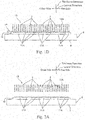
- Fig. 1A illustrates an embodiment of a method of producing a high-density carbon nanotube aggregate of the present invention, showing a step of forming a catalyst layer on a substrate.
- Fig. 1B shows a step subsequent to Fig. 1A , in which the substrate is heated to agglomerate the catalyst layer into a plurality of granules.
- Fig. 1C shows a step subsequent to Fig. 1B , in which a carbon nanotube array is prepared by supplying a source gas to the plurality of granules and growing a plurality of carbon nanotubes.
- Fig. 1D shows a step subsequent to Fig. 1C , in which the carbon nanotube array is cut from the substrate.
- Fig. 1B shows a step subsequent to Fig. 1A , in which the substrate is heated to agglomerate the catalyst layer into a plurality of granules.
- Fig. 1C shows a step subsequent to Fig. 1B , in
- FIG. 2A shows a step subsequent to Fig. 1D , in which the carbon nanotube array is separated from the substrate.
- Fig. 2B shows a step subsequent to Fig. 2A , in which the carbon nanotube array is placed in a heat-resistant container.
- Fig. 2C shows a step subsequent to Fig. 2B , in which the carbon nanotube array is heated to produce a high-density carbon nanotube aggregate.
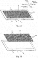
- Fig. 3A is a perspective view of the carbon nanotube array and the substrate shown in Fig. 1C , in which the carbon nanotube array is aligned on the substrate.
- Fig. 3B is a perspective view of the carbon nanotube array and the substrate shown in Fig. 3A , in which the carbon nanotube array is separated from the substrate.
- FIG. 3C is a perspective view of the high-density carbon nanotube aggregate shown in Fig. 2C .
- Fig. 4A illustrates mechanical compression of a carbon nanotube array of Comparative Example 2, showing the carbon nanotube array before compression.
- Fig. 4B shows a step subsequent to Fig. 4A , in which the carbon nanotube array is mechanically compressed from one side.
- Fig. 4C shows a step subsequent to Fig. 4B , in which the carbon nanotube array is mechanically compressed from the other side to prepare a mechanically compressed carbon nanotube array of Comparative Example 2.
- Fig. 5A shows the Raman spectrum of the high-density carbon nanotube aggregate of Example 1.
- Fig. 5B shows the Raman spectrum of the high-density carbon nanotube aggregate of Comparative Example 3.
- Fig. 4A illustrates mechanical compression of a carbon nanotube array of Comparative Example 2, showing the carbon nanotube array before compression.
- Fig. 4B shows a step subsequent to Fig. 4A , in
- FIG. 6 is a graph showing the average bulk density with respect to the heat treatment temperature in Examples 1, 4 to 6 and Comparative Example 1.
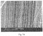
- Fig. 7A shows a microphotograph of a peripheral portion of the high-density carbon nanotube aggregate of Example 1 taken by scanning electron microscope (SEM).
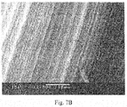
- Fig. 7B shows a SEM photograph of a central portion of the high-density carbon nanotube aggregate of Example 1.
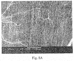
- Fig. 8A shows a SEM photograph of a peripheral portion of the mechanically compressed high-density carbon nanotube aggregate of Comparative Example 2.
- Fig. 8B shows a SEM photograph of a central portion of the mechanically compressed high-density carbon nanotube aggregate of Comparative Example 2.
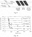
- Fig. 10 is a graph showing the thermal resistance of the high-density carbon nanotube aggregates of Examples.
- the high-density carbon nanotube aggregate 1 may be in a flexible sheet form (film form). Specifically, the high-density carbon nanotube aggregate 1 may have a thickness in a predetermined direction, extend in a surface directions (the longitudinal direction and the lateral direction) orthogonal to the predetermined direction (the thickness direction), and have a flat top surface and a flat bottom surface.
- the thickness of the high-density carbon nanotube aggregate 1 may be, for example, from 10 ⁇ m, or preferably 100 ⁇ m, to 1,000 ⁇ m, or preferably 400 ⁇ m.
- the shape of the high-density carbon nanotube aggregate 1 is not particularly limited, and may be, for example, a polygonal shape or a circular shape, or preferably a rectangular shape when viewed from the thickness direction.
- the dimension of the high-density carbon nanotube aggregate 1 in the longitudinal direction may be, for example, from 1 mm, preferably 10 mm, or more preferably 25 mm, to 300 mm, or preferably 50 mm
- the dimension of the high-density carbon nanotube aggregate 1 in the lateral direction may be, for example, from 1 mm, preferably 10 mm, or more preferably 25 mm, to 200 mm, or more preferably 50 mm.
- the high-density carbon nanotube aggregate 1 may be constituted by a plurality of carbon nanotubes 2.
- the plurality of carbon nanotubes 2 may be oriented in the thickness direction and arranged in a sheet form continuously with each other in the surface direction (the longitudinal direction and the lateral direction) without being continuous with each other in the thickness direction.
- the high-density carbon nanotube aggregate 1 may maintain its shape so that the plurality of carbon nanotubes 2 are in contact with each other.
- any two carbon nanotubes 2 adjacent to each other may be subjected to a van der Waals force acting therebetween.
- Each of the plurality of carbon nanotubes 2 may be any of a single-walled carbon nanotube, a double-walled carbon nanotube, and a multi-walled carbon nanotube, but it is preferably a multi-walled carbon nanotube. These types of carbon nanotubes 2 can be used either singly or combinedly.
- the average outer diameter of each of the plurality of carbon nanotubes 2 may be, for example, from 1 nm, or preferably 5 nm, to 100 nm, preferably 50 nm, or more preferably 20 nm.
- the average length (the average dimension in the direction of orientation) of each of the plurality of carbon nanotubes 2 is not particularly limited, and may be, for example, from 10 ⁇ m, preferably 100 ⁇ m, or more preferably 200 ⁇ m, to 1,000 ⁇ m, preferably 500 ⁇ m, or more preferably 400 ⁇ m.
- the average outer diameter and the average length of the carbon nanotubes 2 are measured by a known method such as electron microscope observation, for example.
- the average bulk density of the plurality of carbon nanotubes 2 may be from greater than 50 mg/cm 3 , or preferably from 60 mg/cm 3 , or more preferably 100 mg/cm 3 , to 300 mg/cm 3 , preferably 200 mg/cm 3 , or more preferably 150 mg/cm 3 .
- the average bulk density of the carbon nanotube 2 may be calculated from, for example, the mass per unit area (basis weight (mg/cm 2 )) and the average length of the carbon nanotubes (measured by SEM (from JEOL Ltd.) or non-contact film thickness meter (from KEYENCE Corporation)).
- the proportion of the bulk density of each portion to the average bulk density (that is, the percentage of the bulk density of a particular (any) portion to the average bulk density of the high-density carbon nanotube aggregate 1 set at 100%) may be from 80%, or preferably 90%, to 120%, or preferably 110%.
- the proportion of the bulk density of each portion of the high-density carbon nanotube aggregate 1 to the average bulk density can be obtained, for example, by equally dividing the high-density carbon nanotube aggregate 1 into a plurality of portions (for example, three portions) having an equal volume, calculating the bulk density of each portion of the equally divided high-density carbon nanotube aggregate 1 in the same manner as the above-mentioned average bulk density, and calculating the percentage of the bulk density of each portion to the above-mentioned average bulk density.
- the average G/D ratio of the high-density carbon nanotube aggregate 1 may be, for example, from 2, preferably 5, more preferably 10, or most preferably 20, to 30, or preferably 25.
- the G/D ratio is the ratio of the spectral intensity of the peak called the G band observed around 1,590 cm -1 to the spectral intensity of the peak called the D band observed around 1,350 cm -1 in the Raman spectrum of the carbon nanotube.
- the spectrum of the D band is derived from a defect of the carbon nanotube and the spectrum of the G band is derived from in-plane vibration of the six-membered ring of carbon.
- the electric conductivity of the high-density carbon nanotube aggregate 1 in the thickness direction may be, for example, from 4,000 S/m, preferably 8,000 S/m, more preferably 15,000 S/m, or most preferably 22,000 S/m, to 50,000 S/m, or preferably 30,000 S/m.
- the electric conductivity may be measured by a known electric conductivity measuring device.
- the thermal conductivity of the high-density carbon nanotube aggregate 1 in the thickness direction maybe, for example, from 5 W/(m ⁇ K), preferably 10 W/(m ⁇ K), more preferably 20 W/(m ⁇ K), or most preferably 30 W/(m ⁇ K), to 60 W/(m ⁇ K), or preferably 40 W/(m ⁇ K).
- the thermal conductivity may be measured by a known thermal conductivity measuring device.
- Such a high-density carbon nanotube aggregate 1 may be used for various industrial products, for example, as a heat conductive sheet or an electroconductive sheet.
- the method of producing the high-density carbon nanotube aggregate 1 may include, for example, preparing a carbon nanotube array 13 placed on the substrate 8 (see Figs. 1A to 1C ) and heating the carbon nanotube array 13 (see Figs. 1D to 2C ).
- the first step of this production method may be to prepare the substrate 8, as shown in Fig. 1A .
- the substrate 8 is not particularly limited, and examples thereof include known substrates used for a chemical vapor deposition method (CVD method), and the substrate 8 may be a commercially available substrate.
- CVD method chemical vapor deposition method
- the substrate 8 include a silicon substrate and a stainless steel substrate 9 having a silicon dioxide film 10 stacked thereon, and the substrate 8 may preferably be a stainless steel substrate 9 having the silicon dioxide film 10 stacked thereon.
- the substrate 8 is a stainless steel substrate 9 having a silicon dioxide film 10 stacked thereon.
- a catalyst layer 11 may be formed on the substrate 8, or preferably on the silicon dioxide film 10.
- a metal catalyst film may be formed on the substrate 8 (or preferably the silicon dioxide film 10) by a known film formation method.
- metal catalyst examples include iron, cobalt, and nickel, and iron is preferred. These metal catalysts can be used either singly or combinedly.
- Examples of the film formation method include vacuum deposition and sputtering, and vacuum deposition is preferred.
- the catalyst layer 11 may be disposed on the substrate 8.
- the silicon dioxide film 10 and the catalyst layer 11 may be formed at the same time by, for example, as disclosed in Japanese Patent Application Publication No. 2014-94856 , applying to the stainless steel substrate 9 a mixture solution in which a silicon dioxide precursor solution and a metal catalyst precursor solution are mixed, and then phase-separating and drying the mixture solution.
- the substrate 8 having the catalyst layer 11 disposed thereon may be heated to a temperature from 700°C to 900°C.
- the catalyst layer 11 may aggregate into a plurality of granules 11A.
- a source gas may be supplied to the heated substrate 8.
- the source gas may contain a hydrocarbon gas (lower hydrocarbon gas) with a carbon number of 1 to 4.
- hydrocarbon gas with a carbon number of 1 to 4 examples include methane gas, ethane gas, propane gas, butane gas, ethylene gas, and acetylene gas, and acetylene gas may be preferred.
- the source gas may contain hydrogen gas, inert gas (for example, helium, argon, etc.), water vapor, and the like, if necessary.
- inert gas for example, helium, argon, etc.
- the concentration of the hydrocarbon gas in the source gas may be, for example, from 1 volume%, or preferably 30 volume%, to 90 volume%, or preferably 50 volume%.
- the supply time of the source gas may be, for example, from 1 minute, or preferably 5 minutes, to 60 minutes, or preferably 30 minutes.
- a plurality of carbon nanotubes 2 may grow from the plurality of granules 11A.
- Fig. 1C shows that one carbon nanotube 2 grows from one granule 11A.
- the present invention is not limited to this, and it may also be possible that a plurality of carbon nanotubes 2 grow from one granule 11A.
- Each of the plurality of carbon nanotubes 2 may extend in the thickness direction of the substrate 8 so as to be substantially parallel to each other on the substrate 8. That is, the plurality of carbon nanotubes 2 may be oriented (vertically oriented) so as to be orthogonal to the substrate 8.
- a carbon nanotube array 13 constituted by the plurality of carbon nanotubes 2 may be formed on the substrate 8.
- such a carbon nanotube array 13 may include a plurality of rows 13A arranged in a longitudinal direction so that a plurality of carbon nanotubes 2 are arranged straight in a lateral direction.
- the average bulk density of the plurality of carbon nanotubes 2 may be, for example, from 10 mg/cm 3 , or preferably 20mg/cm 3 , to 50mg/cm 3 .
- the carbon nanotube array 13 may be separated from the substrate 8, if necessary.
- the base end portions (the end portions on the substrate 8 side) of the plurality of carbon nanotubes 2 may be cut in a lump by, for example, a cutting blade 16, as shown in Fig. 1D .
- Examples of the cutting blade 16 include known metal blades such as a cutter blade and a razor blade, and a cutter blade is preferred.
- the longitudinal dimension of the cutting blade 16 may be larger than that of the carbon nanotube array 13.
- the cutting blade 16 may be placed on the upper surface of the substrate 8 so as to be laterally adjacent to the carbon nanotube array 13, and the cutting blade 16 may be slid in the lateral direction along the upper surface of the substrate 8 .
- the base end portions of the plurality of carbon nanotubes 2 may be cut in a lump, and the carbon nanotube array 13 may be separated from the substrate 8.
- the carbon nanotube array 13 separated from the substrate 8 may be pulled upward. As a result, the carbon nanotube array 13 may be separated from the substrate 8.
- the carbon nanotube array 13 separated from the substrate 8 may retain its shape by van der Waals force or the like acting between adjacent carbon nanotubes 2 among the plurality of carbon nanotubes 2.
- the average G/D ratio of such a carbon nanotube array 13 is, for example, equal to or larger than 1 and less than 2.
- the carbon nanotube array 13 may be heated.
- the carbon nanotube array 13 may be first placed in a heating furnace.
- the heating furnace is not particularly limited, and examples thereof include a resistance heating furnace, an induction heating furnace, and a direct current electric furnace, and a resistance heating furnace is preferred. Further, the heating furnace may be of a batch type or a continuous type.
- the carbon nanotube array 13 may preferably be placed in a heating furnace while being housed in a heat-resistant container 17.
- the heat-resistant container 17 may resist temperatures greater than 2,600°C, and examples thereof include known heat-resistant containers such as a carbon container formed of carbon and a ceramic container formed of ceramic. Among such heat-resistant containers, a carbon container is preferred.
- Such a heat-resistant container 17 may include, for example, a container body 17A opened upward and a lid portion 17B for closing the upper end portion of the container body 17A.
- the shape of the container body 17A is not particularly limited, and examples thereof include a substantially box-like shape opened upward and a substantially cylindrical shape opened upward and closed at the lower end portion.
- the inner dimension of the container body 17A in the vertical direction may be equal to or larger than the dimension of the carbon nanotube array 13 in the vertical direction, and may preferably be larger than the dimension of the carbon nanotube array 13 in the vertical direction. More specifically, the inner dimension of the container body 17A in the vertical direction may be, for example, from 1.0 times, or preferably 1.5 times to 10 times, or preferably 5 times as large as the dimension of the carbon nanotube array 13 in the vertical direction.
- the inner dimensions of the container body 17A in the lateral direction and the longitudinal direction may be larger than the dimensions of the carbon nanotube array 13 in the lateral direction and the longitudinal direction, respectively.
- the inner diameter of the container body 17A may be larger than the dimensions of the carbon nanotube array 13 in the lateral direction and the longitudinal direction.
- the carbon nanotube array 13 may preferably be accommodated in the heat-resistant container 17 so as to be spaced apart from the lid portion 17B in the vertical direction, and the carbon nanotube array 13 may more preferably be arranged so as to be spaced apart from the sidewalls of the container body 17A.
- an inert gas may be introduced into the heating furnace, and the inside air of the heating furnace may be replaced with an inert gas atmosphere.
- the inert gas include nitrogen and argon, and argon is preferred.
- the carbon nanotube array 13 When the carbon nanotube array 13 is accommodated in the heat-resistant container 17, it may be possible to prevent the carbon nanotube array 13 from being blown off due to inflow of inert gas into the heating furnace, purging of the heating furnace, or the like.
- the temperature in the heating furnace may be raised to the heating temperature at a predetermined rate, and then the heating furnace may be left to stand for a predetermined time with the temperature maintained.
- the rate of temperature increase may be, for example, from 1°C/min, preferably 3°C/min, or more preferably 5°C/min, to 40°C/min, preferably 20°C/min, or more preferably less than 10°C/min.
- the heating temperature may be 2,600°C or higher, preferably 2,700°C or higher, or more preferably 2,800°C or higher.
- the heating temperature is equal to or higher than the lower limit described above, it is possible to reliably aggregate the plurality of carbon nanotubes 2 in the carbon nanotube array 13.
- the heating temperature may be lower than the sublimation temperature of the carbon nanotube 2, and is preferably 3,000°C or lower.
- the predetermined time may be, for example, from ten minutes, or preferably one hour, to five hours, or preferably three hours.
- the plurality of carbon nanotubes 2 can be reliably aggregated in the carbon nanotube array 13, and when the predetermined time is equal to or less than the upper limit described above, mass production of the high-density carbon nanotube aggregate can be facilitated.
- the carbon nanotube array 13 may preferably be heated in a no-load state (in a state in which no load is applied to the carbon nanotube array 13, that is, under atmospheric pressure).
- the carbon nanotube array 13 may be placed in the heat-resistant container 17 so as to be spaced apart from the lid portion 17B in the vertical direction and spaced apart from the side walls of the container body 17A, and then the heat-resistant container 17 may be heated in the heating furnace.
- the carbon nanotube array 13 may be heated.
- the crystallinity of the graphene constituting the plurality of carbon nanotubes 2 may be improved in the carbon nanotube array 13, and the orientation (straightness) of the carbon nanotubes 2 maybe improved. Then, in the carbon nanotube array 13, the carbon nanotubes 2 adjacent to each other may aggregate in a bundle shape while maintaining orientation (straightness) thereof by Van der Waals force or the like acting therebetween.
- the whole carbon nanotube array 13 may be uniformly aggregated to prepare a high-density carbon nanotube aggregate 1. Then, the high-density carbon nanotube aggregate 1 may be cooled (for example, naturally cooled) as necessary.
- the vertical dimension (thickness) of the high-density carbon nanotube aggregate 1 may be substantially the same as the vertical dimension (thickness) of the carbon nanotube array 13 prior to the heating, because the plurality of carbon nanotubes 2 aggregate while maintaining the orientation (straightness) thereof. More specifically, the vertical dimension of the high-density carbon nanotube aggregate 1 may be, for example, from 95% to 105% of that of the carbon nanotube array 13 prior to the heating, or it may preferably be 100% of the same.
- the volume of the high-density carbon nanotube aggregate 1 may be, for example, from 5%, preferably 10%, or more preferably 20%, to 90%, preferably 85%, or more preferably 50% of the volume of the carbon nanotube array 13 prior to the aggregation.
- the average bulk density of a plurality of carbon nanotubes 2 oriented in the thickness direction and arranged in a sheet form may be from greater than 50 mg/cm 3 to 200 mg/cm 3 .
- the proportion of the bulk density of each portion of the high-density carbon nanotube aggregate 1 to the average bulk density of the high-density carbon nanotube aggregate 1 may be from 80% to 120%. That is, the high-density carbon nanotube aggregate 1 may have less unevenness of the bulk density over the whole of the high-density carbon nanotube aggregate 1 as compared with the high-density carbon nanotube aggregate prepared by mechanical compression.
- the heat treatment may be performed at least once or may be repeated two or more times.
- the crystallinity of the carbon nanotubes 2 and the average bulk density of the high-density carbon nanotube aggregate 1 can be controlled by appropriately changing the rate of temperature increase and the number of times of the heat treatment.
- the method of producing the high-density carbon nanotube aggregate 1 may preferably include a plurality of times of the heat treatment described above.
- the method of producing the high-density carbon nanotube aggregate 1 may include cooling the carbon nanotube array 13 (the high-density carbon nanotube aggregate 1) after the above-described heat treatment, and includes repetition of the heat treatment and the cooling.
- the heat treatment performed first is referred to as the first stage heat treatment
- the high-density carbon nanotube aggregate 1 subjected to the first heat treatment is referred to as the first stage high-density carbon nanotube aggregate 1.
- the heat treatment performed for the n-th time is referred to as the n-th stage heat treatment (e.g., the second stage heat treatment)
- the high-density carbon nanotube aggregate 1 subjected to the n-th stage heat treatment is referred to as the n-th stage high-density carbon nanotube aggregate 1 (e.g., a second stage high-density carbon nanotube aggregate 1).
- the high-density carbon nanotube aggregate 1 (the first stage high-density carbon nanotube aggregate 1) heated as described above may be cooled to a predetermined cooling temperature or lower (the cooling).
- the method of cooling the high-density carbon nanotube aggregate 1 is not particularly limited, and it can be cooled by known methods or preferably natural cooling.
- the rate of temperature decrease is not particularly limited and may be, for example, from -1°C/min, preferably -5°C/min, or more preferably -50°C/min, to - 300°C/min, or preferably -150°C/min.
- the cooling temperature may be from 2,000°C, preferably 1,000°C, or more preferably 40°C to 0°C.
- the crystallinity of graphene can be reliably improved, and the average G/D ratio of the high-density carbon nanotube aggregate 1 can be reliably improved.
- the difference between the heating temperature and the cooling temperature may be, for example, from 600°C, preferably 1,000°C, or more preferably 2,500°C, to 3,000°C, or preferably 2,900°C.
- the difference between the heating temperature and the cooling temperature is within the above range, the crystallinity of graphene can be reliably improved, and the average G/D ratio of the high-density carbon nanotube aggregate 1 can be reliably improved.
- the high-density carbon nanotube aggregate 1 may be maintained at the cooling temperature or lower for a predetermined time.
- the predetermined time may be, for example, from 1 sec, preferably 10 min, or more preferably 15 min, to 5 hours, preferably 3 hours, or more preferably 1 hour.
- the cooled high-density carbon nanotube aggregate 1 may be heated in the same manner as in the above heat treatment (the second stage heat treatment). Then, the heat treatment and the cooling may be sequentially repeated.
- the number of times of repeating the heat treatment and the cooling may be, for example, from 2 to 100, or preferably 10, and the most preferable may be two.
- the average G/D ratio of the high-density carbon nanotube aggregate 1 can be reliably improved.
- the number of times of repetition is equal to or less than the above upper limit, particularly when it is two, mass productivity of the high-density carbon nanotube aggregate 1 can be improved.
- the n-th stage high-density carbon nanotube aggregate 1 may be prepared.
- the volume of the n-th stage high-density carbon nanotube aggregate 1 may be, for example, from 80% to 100% of the volume of the first stage high-density carbon nanotube aggregate 1, and the range of the average bulk density of the n-th stage high-density carbon nanotube aggregate 1 may be the same as that of the first stage high-density carbon nanotube aggregate 1. That is, in the n-th stage heat treatment, the rate of increase in the bulk density of the high-density carbon nanotube aggregate 1 is smaller than that in the first stage heat treatment.
- the crystallinity of the graphene constituting the carbon nanotube may be further improved. More specifically, the average G/D ratio of the n-th stage high-density carbon nanotube aggregate 1 may be, for example, from greater than 1 time, or preferably from 1.2 times, to 3 times, or preferably 2 times as large as the average G/D ratio of the first stage high-density carbon nanotube aggregate 1. The average G/D ratio of the first stage high-density carbon nanotube aggregate 1 may be, for example, from 2 to 20.
- the method of producing the high-density carbon nanotube aggregate 1 may preferably include supplying a liquid to the carbon nanotube array 13 (the high-density carbon nanotube aggregate 1) after the above-described heat treatment (a liquid treatment).
- Examples of a method of supplying the liquid to the high-density carbon nanotube aggregate 1 may include spraying the liquid on the high-density carbon nanotube aggregate 1 or immersing the high-density carbon nanotube aggregate 1 in the liquid.
- the method of immersing the high-density carbon nanotube aggregate 1 in the liquid may be preferable.
- the liquid may volatilize at a normal temperature and pressure (a volatile liquid), and examples of such a liquid include water and organic solvents.
- the organic solvent include lower (C1-3) alcohols (e.g., methanol, ethanol, propanol), ketones (e.g., acetone), ethers (e.g., diethyl ether, tetrahydrofuran), alkyl esters (e.g., ethyl acetate), halogenated aliphatic hydrocarbons (e.g., chloroform, dichloromethane), polar aprotic compounds (e.g., N-methylpyrrolidone, dimethylformamide), aliphatic hydrocarbons (e.g., hexane, heptane, octane), alicyclic hydrocarbons (e.g., cyclohexane, methylcyclohexane), aromatic hydrocarbons (e.g., benzene, tol
- liquids water, lower alcohols, and aliphatic hydrocarbons are preferred. These liquids can be used either singly or combinedly.
- the temperature in the liquid treatment may be, for example, from 5°C, preferably 10°C, to 40°C, preferably 30°C.
- the supply time of the liquid may be, for example, from 3 minute, or preferably 5 minutes to 120 minutes, or preferably 90 minutes.
- the high-density carbon nanotube aggregate 1 may be dried (for example, naturally dried) as necessary by a known method.
- the high-density carbon nanotube aggregate 1 may be subjected to a liquid treatment.
- the liquid When the liquid is supplied to the high-density carbon nanotube aggregate 1, the liquid is vaporized, whereby the plurality of carbon nanotubes 2 aggregate with each other while maintaining the orientation, and the density of the high-density carbon nanotube aggregate 1 may be further increased.
- the volume of the high-density carbon nanotube aggregate 1 subjected to the liquid treatment may be, for example, from 30%, or preferably 50%, to 90%, preferably 80%, or more preferably 70% of the volume of the high-density carbon nanotube aggregate 1 prior to the liquid treatment.
- the average bulk density of a plurality of carbon nanotubes 2 may be from 100 mg/cm 3 to 300 mg/cm 3 .
- heat treatment, the cooling, and the liquid treatment may be repeated sequentially. Further, it may also be possible to repeat the heat treatment and the cooling sequentially and then perform the liquid treatment, or to perform the first stage heat treatment and the liquid treatment and then repeat the heat treatment and the cooling sequentially.
- the carbon nanotube array 13 constituted by a plurality of carbon nanotubes 2 may be heated to a temperature from 2,600°C to 3,000°C, as shown in Fig. 2C .
- the crystallinity of the graphene constituting the carbon nanotubes 2 may be improved, and the orientation (straightness) of the carbon nanotubes 2 may be improved.
- the plurality of carbon nanotubes 2 may aggregate in the carbon nanotube array 13.
- the high-density carbon nanotube aggregate 1 it may be possible to increase the average density of the plurality of carbon nanotubes 2 while maintaining the orientation of the plurality of carbon nanotubes 2, and it is also possible to uniform the density of the plurality of carbon nanotubes 2, as compared with the case where the high-density carbon nanotube aggregate 1 is prepared by aggregation caused by liquid evaporation or by mechanical compression.
- the carbon nanotube array 13 may be heated after being separated from the substrate 8.
- dissolution of the substrate 8 can be suppressed, and as a result, it can be suppressed that the dissolved substrate 8 adhere to the carbon nanotube array 13 or a heating furnace.
- the carbon nanotube array 13 may be heated in the no-load state. Therefore, smooth aggregation of the plurality of carbon nanotubes 2 can be secured, and the breakage of the high-density carbon nanotube aggregate 1 can be suppressed.
- thermo treatment it may be possible to perform the heat treatment two or more times. More specifically, it may also be possible to sequentially repeat the heat treatment of the carbon nanotube array 13 and the cooling of the carbon nanotube array 13.
- the crystallinity of the graphene constituting the carbon nanotube 2 can be further improved, and as a result, the thermal conductivity and the electric conductivity of the high-density carbon nanotube aggregate 1 (the n-th stage high-density carbon nanotube aggregate 1) can be improved reliably.
- the carbon nanotubes 2 adjacent to each other in the high-density carbon nanotube aggregate 1 may aggregate while maintaining the orientation thereof. Therefore, the density of the high-density carbon nanotube aggregate 1 can be further increased.
- the following Examples will illustrate the present invention more specifically, but the present invention is not limited to these Examples.
- the following description contains specific numerical values such as compounding ratio (content ratio), physical property values, and parameters. These specific numerical values can be replaced with the upper limit values (defined with “to” or “less than”) or the lower limit values (defined with “from” or “greater than") of the compounding ratio (content ratio), physical property values, parameters that correspond to the specific numerical values and described in "DESCRIPTION OF EXAMPLE EMBODIMENTS" above.
- a silicon dioxide film was stacked on the entire stainless steel substrate, and then iron was deposited as a catalyst layer on the silicon dioxide film.
- the substrate had a substantially rectangular shape in a plan view.
- the substrate was heated to 700°C and a raw material gas (acetylene gas) was supplied to the catalyst layer for 15 minutes.
- a raw material gas acetylene gas
- the plurality of carbon nanotubes extended substantially in parallel with each other and were oriented (vertically oriented) so as to be orthogonal to the substrate.
- the average outer diameter of the carbon nanotubes was about 12 nm, and the average length of the carbon nanotubes was about 200 ⁇ m.
- the dimension of the carbon nanotube array in the longitudinal direction was 20 mm
- the dimension of the carbon nanotube array in the lateral direction was 30 mm
- the dimension of the carbon nanotube array in the vertical direction was the same as the average length of the carbon nanotubes. Therefore, the area of the carbon nanotube array was 600 mm 2 , and the volume of the same was 120 mm 3 .
- the average bulk density of the plurality of carbon nanotubes in the carbon nanotube array was about 50 mg/cm 3 .
- the cutter blade was moved along the substrate, and the carbon nanotube array was cut away from the substrate for separation.
- the carbon container includes a container body opened upward and a lid portion closing the upper end portion of the container body.
- the inner dimension of the container body in the vertical direction was 1 mm
- the inner dimension in the longitudinal direction was 45 mm
- the inner dimension in the lateral direction was 45 mm.
- the carbon nanotube array was contained in the carbon container so as to be spaced from the lid portion in the vertical direction and spaced from the side walls of the carbon container in the longitudinal direction and the lateral direction.
- the carbon nanotube array was in a no-load state when contained in the carbon container.
- the gas in the resistance heating furnace was replaced with an argon atmosphere, and then the argon atmosphere was heated to 2,800°C at a rate of 10°C/min and maintained at 2,800°C for two hours.
- the carbon nanotube array contained in the carbon container was heated in the no-load state to prepare a high-density carbon nanotube aggregate.
- the high-density carbon nanotube aggregate was then cooled to the room temperature by natural cooling (the rate of temperature decrease: -100°C/min).
- the dimension of the high-density carbon nanotube aggregate in the longitudinal direction was 11 mm
- the dimension of the high-density carbon nanotube aggregate in the lateral direction was 22 mm
- the dimension of the high-density carbon nanotube aggregate in the vertical direction was about 200 ⁇ m.
- the area of the high-density carbon nanotube aggregate was 242 mm 2 , and the volume of the same was 48 mm 3 .
- a carbon nanotube array including a plurality of carbon nanotubes having an average length of about 100 ⁇ m was formed in the same manner as in Example 1.
- the dimension of the carbon nanotube array in the longitudinal direction was 20 mm
- the dimension of the carbon nanotube array in the lateral direction was 30 mm
- the dimension of the carbon nanotube array in the vertical direction was about 100 ⁇ m.
- the average bulk density of the plurality of carbon nanotubes in the carbon nanotube array was about 50 mg/cm 3 .
- Example 1 the carbon nanotube array was separated from the substrate, subjected to a heat treatment, and then allowed to cool naturally to obtain a high-density carbon nanotube aggregate.
- the dimension of the high-density carbon nanotube aggregate in the longitudinal direction was 11 mm
- the dimension of the high-density carbon nanotube aggregate in the lateral direction was 22 mm
- the dimension of the high-density carbon nanotube aggregate in the vertical direction was about 100 ⁇ m.
- a carbon nanotube array including a plurality of carbon nanotubes having an average length of about 300 ⁇ m was formed in the same manner as in Example 1.
- the dimension of the carbon nanotube array in the longitudinal direction was 20 mm
- the dimension of the carbon nanotube array in the lateral direction was 30 mm
- the dimension of the carbon nanotube array in the vertical direction was about 300 ⁇ m.
- the average bulk density of the plurality of carbon nanotubes in the carbon nanotube array was about 50 mg/cm 3 .
- Example 1 the carbon nanotube array was separated from the substrate, subjected to a heat treatment, and then allowed to cool naturally to obtain a high-density carbon nanotube aggregate.
- the dimension of the high-density carbon nanotube aggregate in the longitudinal direction was 11 mm
- the dimension of the high-density carbon nanotube aggregate in the lateral direction was 22 mm
- the dimension of the high-density carbon nanotube aggregate in the vertical direction was about 300 ⁇ m.
- a high-density carbon nanotube aggregate was obtained in the same manner as in Example 1 except that the heating temperature of the carbon nanotube array was changed from 2,800°C to 2,600°C.
- the dimension of the high-density carbon nanotube aggregate in the longitudinal direction was 18 mm
- the dimension of the high-density carbon nanotube aggregate in the lateral direction was 27 mm
- the dimension of the high-density carbon nanotube aggregate in the vertical direction was about 200 ⁇ m.
- a high-density carbon nanotube aggregate was prepared in the same manner as in Example 1 except that the heating temperature of the carbon nanotube array was changed from 2,800°C to 2,900°C.
- the dimension of the high-density carbon nanotube aggregate in the longitudinal direction was 13 mm
- the dimension of the high-density carbon nanotube aggregate in the lateral direction was 18 mm
- the dimension of the high-density carbon nanotube aggregate in the vertical direction was about 200 ⁇ m.
- a high-density carbon nanotube aggregate was prepared in the same manner as in Example 1 except that the heating temperature of the carbon nanotube array was changed from 2,800°C to 3,000°C.
- the dimension of the high-density carbon nanotube aggregate in the longitudinal direction was 12 mm
- the dimension of the high-density carbon nanotube aggregate in the lateral direction was 17 mm
- the dimension of the high-density carbon nanotube aggregate in the vertical direction was about 200 ⁇ m.
- a high-density carbon nanotube aggregate was prepared in the same manner as in Example 5 except that a carbon plate having a weight of about 2 kg was placed on the carbon nanotube array when the carbon nanotube array was heated.
- Example 7 resulted in breakage of a part of the high-density carbon nanotube aggregate 1.
- a carbon nanotube array separated from the substrate was prepared in the same manner as in Example 1 except that the average length of the carbon nanotubes was about 300 ⁇ m.
- Example 2 the separated carbon nanotube array was placed in a carbon container, and the carbon container was placed in a resistance heating furnace.
- the gas in the resistance heating furnace was replaced with an argon atmosphere, and then the argon atmosphere was heated to 2,800°C at a rate of 3°C/min (in a range from 2,400 to 2,800°C) and maintained at 2,800°C for two hours (the first stage heat treatment).
- the carbon nanotube array contained in the carbon container was heated in the no-load state to prepare a first stage high-density carbon nanotube aggregate.
- the first stage high-density carbon nanotube aggregate was then cooled to the room temperature by natural cooling (the rate of temperature decrease: about - 100°C/min) (the cooling).
- the dimension of the first stage high-density carbon nanotube aggregate in the longitudinal direction was 11 mm
- the dimension of the first stage high-density carbon nanotube aggregate in the lateral direction was 22 mm
- the dimension of the first stage high-density carbon nanotube aggregate in the vertical direction was about 300 ⁇ m.
- the area of the first stage high-density carbon nanotube aggregate was 242 mm 2 , and the volume of the same was 72.6 mm 3 .
- the first stage high-density carbon nanotube aggregate was placed in the carbon container again, and the carbon container was placed in the resistance heating furnace.
- the gas in the resistance heating furnace was replaced with an argon atmosphere, and then the argon atmosphere was heated to 2,800°C at a rate of 3°C/min (in a range from 2,400 to 2,800°C) and maintained at 2,800°C for two hours (the second stage heat treatment).
- the second stage high-density carbon nanotube aggregate was then cooled to the room temperature by natural cooling (about -100°C/min) (the cooling).
- the dimensions of the second stage high-density carbon nanotube aggregate were the same as the dimensions of the first stage high-density carbon nanotube aggregate.
- a second stage high-density carbon nanotube aggregate was prepared in the same manner as in Example 8 except that the heating temperature in the first stage heat treatment was changed to 2,600°C and the heating temperature in the second stage heat treatment was changed to 2,600°C.
- the dimensions of the first stage high-density carbon nanotube aggregate and the second stage high-density carbon nanotube aggregate in the longitudinal direction were 18 mm, the dimensions of these high-density carbon nanotube aggregates in the lateral direction were 27 mm, and the dimensions of these high-density carbon nanotube aggregates in the vertical direction were about 300 ⁇ m.
- a first stage high-density carbon nanotube aggregate was prepared in the same manner as in Example 8. The second stage heat treatment was not performed.
- a first stage high-density carbon nanotube aggregate was prepared in the same manner as in Example 8 except that the rate of temperature increase was changed to 1°C/min. The second stage heat treatment was not performed.
- Example 8 a carbon nanotube array was subjected to the first stage heat treatment, cooled from 2,800°C to 2,000°C at a rate of 5°C/min, and then cooled to the room temperature by natural cooling (the rate of temperature decrease: -100°C/min), thereby to prepare a first stage high-density carbon nanotube aggregate.
- the second stage heat treatment was not performed.
- a first stage high-density carbon nanotube aggregate was prepared in the same manner as in Example 8 except that the heating time in the first stage heat treatment was changed to four hours. The second stage heat treatment was not performed.
- a carbon nanotube array separated from the substrate was prepared in the same manner as in Example 1 except that the average length of the carbon nanotubes was about 100 ⁇ m.
- the dimension of the carbon nanotube array in the longitudinal direction was 16 mm
- the dimension of the carbon nanotube array in the lateral direction was 15 mm
- the dimension of the carbon nanotube array in the vertical direction was the same as the average length of the carbon nanotubes. Therefore, the area of the carbon nanotube array was 240 mm 2 , and the volume of the same was 24 mm 3 .
- Example 2 the separated carbon nanotube array was placed in a carbon container, and the carbon container was placed in a resistance heating furnace.
- the inner dimension of the container body of the carbon container in the vertical direction was 0.5 mm.
- the gas in the resistance heating furnace was replaced with an argon atmosphere, and then the argon atmosphere was heated to 2,800°C at a rate of 3°C/min (in a range from 2,400 to 2,800°C) and maintained at 2,800°C for two hours.
- the carbon nanotube array contained in the carbon container was heated in the no-load state to prepare a high-density carbon nanotube aggregate.
- the high-density carbon nanotube aggregate was then cooled to the room temperature by natural cooling (about -100°C/min).
- the dimension of the high-density carbon nanotube aggregate in the longitudinal direction was 10.2 mm
- the dimension of the high-density carbon nanotube aggregate in the lateral direction was 9.2 mm
- the dimension of the high-density carbon nanotube aggregate in the vertical direction was about 100 ⁇ m.
- the area of the high-density carbon nanotube aggregate was 93.8 mm 2 , and the volume of the same was 9.38 mm 3 .
- the high-density carbon nanotube aggregate was subjected to the liquid treatment.
- the dimension of the liquid-treated high-density carbon nanotube aggregate in the longitudinal direction was 7.5 mm, the dimension of the same in the lateral direction was 7.5 mm, and the dimension of the same in the vertical direction was about 100 ⁇ m.
- the area of the high-density carbon nanotube aggregate subjected to the liquid treatment was 56.3 mm 2 , and the volume of the same was 5.63 mm 3 .
- a heated carbon nanotube array (hereinafter referred to as the low-temperature heated carbon nanotube array) was prepared in the same manner as in Example 1 except that the heating temperature of the carbon nanotube array was changed from 2,800°C to 2,200°C.
- the dimension of the low-temperature heated carbon nanotube array in the longitudinal direction was 20 mm
- the dimension of the low-temperature heated carbon nanotube array in the lateral direction was 30 mm
- the dimension of the low-temperature heated carbon nanotube array in the vertical direction was about 200 ⁇ m.
- a carbon nanotube array separated from the substrate was prepared in the same manner as in Example 1.
- the carbon nanotube array was placed on a horizontal plane, the carbon nanotube array was mechanically compressed from one side in the lateral direction so that the dimension thereof in the lateral direction was 21 mm, and then the carbon nanotube array was mechanically compressed from the other side in the lateral direction so that the dimension thereof in the lateral direction was 12 mm.
- the dimension of the mechanically compressed carbon nanotube array in the longitudinal direction was 20 mm
- the dimension of the mechanically compressed carbon nanotube array in the lateral direction was 12 mm
- the dimension of the mechanically compressed carbon nanotube array in the vertical direction was about 200 ⁇ m.
- a carbon nanotube array including a plurality of carbon nanotubes having an average length of about 200 ⁇ m was prepared in the same manner as in Example 1. The carbon nanotube array was not heated.
- a carbon nanotube array including a plurality of carbon nanotubes having an average length of about 100 ⁇ m was prepared in the same manner as in Example 1. The carbon nanotube array was not heated.
- a carbon nanotube array including a plurality of carbon nanotubes having an average length of about 300 ⁇ m was prepared in the same manner as in Example 1. The carbon nanotube array was not heated.
- a carbon nanotube array was prepared in the same manner as in Example 14. The carbon nanotube array was not heated but subjected to the liquid treatment in the same manner as in Example 14.
- the orientation of a plurality of carbon nanotubes was disordered, and the plurality of carbon nanotubes aggregated locally at a plurality of sites, and were not uniformly densified.
- the carbon nanotube array had a porous structure, and the plurality of carbon nanotubes were disintegrated.
- Fig. 5A shows the Raman spectrum of the high-density carbon nanotube aggregate of Example 1
- Fig. 5B shows the Raman spectrum of the carbon nanotube array of Comparative Example 3.
- the average bulk densities were calculated from the mass per unit area (basis weight (mg/cm 2 )) and the length of the carbon nanotubes (measured by SEM (from JEOL Ltd.) or non-contact film thickness meter (from KEYENCE Corporation)).
- Fig. 6 shows a graph of the average bulk density with respect to the heat treatment temperature.
- the following method was used to measure the bulk density at parts of the high-density carbon nanotube aggregates obtained in Examples and the carbon nanotube arrays obtained in Comparative Examples.
- each of the high-density carbon nanotube aggregates was equally divided into three portions arranged in the lateral direction as shown in Fig. 9 .
- One side portion of the high-density carbon nanotube aggregate (the carbon nanotube array) in the lateral direction was defined as one-side peripheral portion
- a central portion of the high-density carbon nanotube aggregate (the carbon nanotube array) in the lateral direction was defined as a central portion
- the other side portion of the high-density carbon nanotube aggregate (the carbon nanotube array) in the lateral direction was defined as the other-side peripheral portion.
- the bulk densities of the one-side peripheral portion, the central portion, and the other-side peripheral portion were calculated in the same manner as in the calculation of the average bulk density described above.
- Table 1 shows the bulk densities of the one-side peripheral portion and the central portion.
- the bulk density in the one-side peripheral portion was approximately the same as the bulk density in the other-side peripheral portion.
- the bulk density of the other-side peripheral portion was 95 mg/cm 3 .
- Fig. 7A shows a scanning electron microscope (SEM) photograph of a peripheral portion of the high-density carbon nanotube aggregate of Example 1
- Fig. 7B shows a SEM photograph of a central portion of the high-density carbon nanotube aggregate of Example 1.
- Fig. 8A shows a SEM photograph of a peripheral portion of the mechanically compressed carbon nanotube array of Comparative Example 2
- Fig. 8B shows a SEM photograph of a central portion of the mechanically compressed carbon nanotube array of Comparative Example 2.
- Figs. 7A to 8B show that, in each of the peripheral portion and the central portion of the high-density carbon nanotube aggregate of Example 1, the plurality of carbon nanotubes aggregated in a bundle form while maintaining the orientation thereof, and the bundles of the carbon nanotubes were arranged densely.
- the electric conductivity in the thickness direction was measured by an electric conductivity measurement device (from KEITHLEY) in the high-density carbon nanotube aggregates obtained in Examples and the carbon nanotube arrays obtained in Comparative Examples.
- the results are listed in Table 1. Since the high-density carbon nanotube aggregate obtained in Example 7 was partially broken, the electrical conductivity thereof was not measured.
- the thermal resistance in the thickness direction was measured by a thermal resistance measurement device (product name: T3Ster DynTIM Tester from Mentor Graphics Corporation) in the high-density carbon nanotube aggregates obtained in Examples and the carbon nanotube arrays obtained in Comparative Examples.
- each of the high-density carbon nanotube aggregates was sandwiched from the outside in the thickness direction (the direction of orientation of the carbon nanotubes) by a heater and a cold stage provided in the thermal resistance measuring device, and was pressurized by the heater with a predetermined pressure from the outside in the thickness direction. Then, the thermal resistance at each pressure was measured. The results are shown in Fig. 10 .
- Second Stage Heat Treatment Heating Temp Heating Time G/D Ratio Average Bulk Density Rate of Change in Average Thermal Conductivity Heating Temp. Heating Time G/D Ratio Average Bulk Density Rate of Change in Average Thermal Conductivity [°C] [h] [mg/cm 3 ] Density [W/(m ⁇ K)] [°C] [h] [mg/cm 3 ] Density [W/(m ⁇ K)]
- Example 8 2800 2 18 125 2.5 25 2800 2 22 125 2.5 30
- Example 9 2600 2 13.3 60 1.2 10 2600 2 - 60 1.2 - Example 10 2800 2 18 125 2.5 25 - Example 11 2800 2 18 125 2.5 25 Example 12 2800 2 18 125 2.5 25
- the method of producing a high-density carbon nanotube aggregate of the present invention can be applied to production of high-density carbon nanotube aggregates used for various industrial products.
Landscapes
- Chemical & Material Sciences (AREA)
- Engineering & Computer Science (AREA)
- Nanotechnology (AREA)
- Organic Chemistry (AREA)
- Materials Engineering (AREA)
- Inorganic Chemistry (AREA)
- Crystallography & Structural Chemistry (AREA)
- General Physics & Mathematics (AREA)
- Physics & Mathematics (AREA)
- Condensed Matter Physics & Semiconductors (AREA)
- Chemical Kinetics & Catalysis (AREA)
- Analytical Chemistry (AREA)
- Composite Materials (AREA)
- Manufacturing & Machinery (AREA)
- Life Sciences & Earth Sciences (AREA)
- General Life Sciences & Earth Sciences (AREA)
- Geology (AREA)
- Carbon And Carbon Compounds (AREA)
Abstract


Description
- The present invention relates to a high-density carbon nanotube aggregate and a method of producing the high-density carbon nanotube aggregate.
- A carbon nanotube is known to have an excellent mechanical strength, thermal conductivity, and electric conductivity. It has been studied to grow a plurality of carbon nanotubes to make a carbon nanotube array and use such carbon nanotube arrays in various industrial products.
- It is desired to increase the density of the plurality of carbon nanotubes in the carbon nanotube array so as to further increase the thermal conductivity and the electric conductivity. Various methods of producing a carbon nanotube array having a high density have been studied.
- For example, a method of producing an oriented carbon nanotube bulk aggregate has been proposed, in which the chemical vapor deposition is used to grow a plurality of carbon nanotubes on a substrate so as to be oriented vertically to the substrate surface, then the plurality of carbon nanotubes are separated from the substrate, the plurality of separated carbon nanotubes are exposed to a liquid such as water and then dried (see, e.g., Patent Document 1).
- Through this method of producing the oriented carbon nanotube bulk aggregate, one can produce an oriented carbon nanotube bulk aggregate having a density of 0.2 to 1.5 g/cm3.
- Patent Document 1: Japanese Patent Application Publication No.
2007-182352 - However, in the method of producing the oriented carbon nanotube bulk aggregate disclosed in
Patent Document 1, the orientation of the plurality of carbon nanotubes may be disordered when the plurality of carbon nanotubes are exposed to the liquid, and thus, it is difficult to maintain the orientation of the plurality of carbon nanotubes in the oriented carbon nanotube bulk aggregate. - Therefore, in such an oriented carbon nanotube bulk aggregate, there is limitation in increasing the thermal conductivity and the electric conductivity in the direction of the orientation of the carbon nanotubes.
- One object of the present invention is to provide a high-density carbon nanotube aggregate and a method of producing the high-density carbon nanotube aggregate that can increase the thermal conductivity and the electric conductivity in the direction of the orientation of the carbon nanotubes.
- The first aspect of the present invention includes a method of producing a high-density carbon nanotube aggregate comprising the steps of: preparing a carbon nanotube array including a plurality of carbon nanotubes aligned on a substrate and oriented vertically to the substrate; and heating the carbon nanotube array to 2,600°C or higher.
- According to such a method, a carbon nanotube array constituted by a plurality of carbon nanotubes oriented vertically to the substrate is heated to 2,600°C or higher. Therefore, the crystallinity of the graphene constituting the carbon nanotube is improved and the orientation (straightness) of the carbon nanotube is improved.
- When the orientation (straightness) of the carbon nanotube is improved, carbon nanotubes adjacent to each other aggregate in the carbon nanotube array.
- As a result, in the high-density carbon nanotube aggregate, it is possible to increase the average density of the plurality of carbon nanotubes while maintaining the orientation of the plurality of carbon nanotubes, and it is also possible to uniform the density of the plurality of carbon nanotubes. Thus, in the high-density carbon nanotube aggregate, it is possible to improve both the thermal conductivity and the electric conductivity in the direction of orientation of the carbon nanotubes.
- That is, according to the method of producing a high-density carbon nanotube aggregate of the present invention, it is possible to produce in a simple manner a high-density carbon nanotube aggregate having an improved thermal conductivity and electric conductivity in the direction of orientation of the carbon nanotube.
- The second aspect of the present invention includes the method of producing a high-density carbon nanotube aggregate of the first aspect, wherein heating the carbon nanotube array comprises: separating the carbon nanotube array from the substrate; and then heating the carbon nanotube array.
- According to such a method, the carbon nanotube array separated from the substrate is subjected to a heat treatment. Therefore, in the carbon nanotube array, the plurality of carbon nanotubes can be smoothly aggregated so as to maintain the orientation.
- In addition, when the carbon nanotube array aligned on the substrate is heated to 2,600°C or higher, the substrate dissolves and the dissolved substrate may be adhered to the carbon nanotube array or a heating furnace for heating the carbon nanotube array.
- On the other hand, according to the above method, the carbon nanotube array separated from the substrate is subjected to heat treatment. Therefore, dissolution of the substrate can be suppressed, and as a result, it can be suppressed that the dissolved substrate adhere to the carbon nanotube array or a heating furnace.
- The third aspect of the present invention includes the method of producing a high-density carbon nanotube aggregate of the first or second aspect, wherein heating the carbon nanotube array comprises heating the carbon nanotube array in a no-load state.
- However, when heat treatment is performed in a state where a load is applied to the carbon nanotube array, the aggregation of the plurality of carbon nanotubes is inhibited, and the high-density carbon nanotube aggregate may be broken due to the load.
- On the other hand, according to the above method, the carbon nanotube array is heated in a no-load state. Therefore, smooth aggregation of the plurality of carbon nanotubes is secured, and the breakage of the high-density carbon nanotube aggregate can be suppressed.
- The fourth aspect of the present invention includes the method of producing a high-density carbon nanotube aggregate of any one of the first to third aspects, further comprising cooling the carbon nanotube array to 2,000°C or lower after heating the carbon nanotube array, wherein the steps of heating the carbon nanotube array and cooling the carbon nanotube array are repeated sequentially.
- According to such a method, the step of heating the carbon nanotube array and the step of cooling the carbon nanotube array are sequentially repeated. Therefore, it is possible to further improve the crystallinity of the graphene constituting the carbon nanotube. As a result, the thermal conductivity and the electric conductivity of the high-density carbon nanotube aggregate can be reliably improved.
- The fifth aspect of the present invention includes the method of producing a high-density carbon nanotube aggregate of any one of the first to fourth aspect, further comprising supplying a liquid to the carbon nanotube array after heating the carbon nanotube array.
- According to such a method, a liquid is supplied to the heated carbon nanotube array. However, in the heated carbon nanotube array, the average density of the plurality of carbon nanotubes is increased. Therefore, even when the liquid is supplied, the orientation of the plurality of carbon nanotubes can be secured.
- Then, as the liquid is vaporized, carbon nanotubes adjacent to each other are aggregated in the heated carbon nanotube array. Therefore, the density of the high-density carbon nanotube aggregate can be further increased.
- The sixth aspect of the present invention includes a high-density carbon nanotube aggregate produced by the method of producing a high-density carbon nanotube aggregate of any one of the first to fifth aspects.
- Therefore, it is possible to improve both the thermal conductivity and the electric conductivity in the direction of orientation of the carbon nanotube.
- The seventh aspect of the present invention includes a high-density carbon nanotube aggregate, comprising: a plurality of carbon nanotubes oriented in a predetermined direction, the plurality of carbon nanotubes being arranged in a sheet form continuously with each other in a direction orthogonal to the predetermined direction without being continuous with each other in the predetermined direction, wherein an average bulk density of the plurality of carbon nanotubes arranged in the sheet form is from greater than 50 mg/cm3 to 200 mg/cm3, in the plurality of carbon nanotubes arranged in the sheet form, a proportion of bulk density of each portion to the average bulk density is from 80% to 120%, and a shape of the high-density carbon nanotube aggregate is maintained such that the plurality of carbon nanotubes are in contact with each other.
- With this arrangement, the average bulk density of a plurality of carbon nanotubes oriented in a predetermined direction and arranged in a sheet form is from greater than 50 mg/cm3 to 200 mg/cm3. In the plurality of carbon nanotubes arranged in a sheet form, the proportion of the density of each portion to the average bulk density is from 80% to 120%.
- Therefore, it is possible to improve both the thermal conductivity and the electric conductivity in the direction of orientation of the carbon nanotube.
- According to the method of producing a high-density carbon nanotube aggregate of the present invention, it is possible to produce in a simple manner a high-density carbon nanotube aggregate having an improved thermal conductivity and electric conductivity in the direction of orientation of the carbon nanotube.
- Further, in the high-density carbon nanotube aggregate of the present invention, it is possible to improve both the thermal conductivity and the electric conductivity in the direction of orientation of the carbon nanotube.
-
Fig. 1A illustrates an embodiment of a method of producing a high-density carbon nanotube aggregate of the present invention, showing a step of forming a catalyst layer on a substrate.Fig. 1B shows a step subsequent toFig. 1A , in which the substrate is heated to agglomerate the catalyst layer into a plurality of granules.Fig. 1C shows a step subsequent toFig. 1B , in which a carbon nanotube array is prepared by supplying a source gas to the plurality of granules and growing a plurality of carbon nanotubes.Fig. 1D shows a step subsequent toFig. 1C , in which the carbon nanotube array is cut from the substrate.Fig. 2A shows a step subsequent toFig. 1D , in which the carbon nanotube array is separated from the substrate.Fig. 2B shows a step subsequent toFig. 2A , in which the carbon nanotube array is placed in a heat-resistant container.Fig. 2C shows a step subsequent toFig. 2B , in which the carbon nanotube array is heated to produce a high-density carbon nanotube aggregate.Fig. 3A is a perspective view of the carbon nanotube array and the substrate shown inFig. 1C , in which the carbon nanotube array is aligned on the substrate.Fig. 3B is a perspective view of the carbon nanotube array and the substrate shown inFig. 3A , in which the carbon nanotube array is separated from the substrate.Fig. 3C is a perspective view of the high-density carbon nanotube aggregate shown inFig. 2C .Fig. 4A illustrates mechanical compression of a carbon nanotube array of Comparative Example 2, showing the carbon nanotube array before compression.Fig. 4B shows a step subsequent toFig. 4A , in which the carbon nanotube array is mechanically compressed from one side.Fig. 4C shows a step subsequent toFig. 4B , in which the carbon nanotube array is mechanically compressed from the other side to prepare a mechanically compressed carbon nanotube array of Comparative Example 2.Fig. 5A shows the Raman spectrum of the high-density carbon nanotube aggregate of Example 1.Fig. 5B shows the Raman spectrum of the high-density carbon nanotube aggregate of Comparative Example 3.Fig. 6 is a graph showing the average bulk density with respect to the heat treatment temperature in Examples 1, 4 to 6 and Comparative Example 1.Fig. 7A shows a microphotograph of a peripheral portion of the high-density carbon nanotube aggregate of Example 1 taken by scanning electron microscope (SEM).Fig. 7B shows a SEM photograph of a central portion of the high-density carbon nanotube aggregate of Example 1.Fig. 8A shows a SEM photograph of a peripheral portion of the mechanically compressed high-density carbon nanotube aggregate of Comparative Example 2.Fig. 8B shows a SEM photograph of a central portion of the mechanically compressed high-density carbon nanotube aggregate of Comparative Example 2.Fig. 9 illustrates a method of measuring the bulk density of each portion of the high-density carbon nanotube aggregates of Examples 1 to 7 and the carbon nanotube arrays of Comparative Examples 1 to 5.Fig. 10 is a graph showing the thermal resistance of the high-density carbon nanotube aggregates of Examples. - As shown in
Fig. 3C , the high-densitycarbon nanotube aggregate 1 may be in a flexible sheet form (film form). Specifically, the high-densitycarbon nanotube aggregate 1 may have a thickness in a predetermined direction, extend in a surface directions (the longitudinal direction and the lateral direction) orthogonal to the predetermined direction (the thickness direction), and have a flat top surface and a flat bottom surface. - The thickness of the high-density
carbon nanotube aggregate 1 may be, for example, from 10 µm, or preferably 100 µm, to 1,000 µm, or preferably 400 µm. - The shape of the high-density
carbon nanotube aggregate 1 is not particularly limited, and may be, for example, a polygonal shape or a circular shape, or preferably a rectangular shape when viewed from the thickness direction. - When the high-density
carbon nanotube aggregate 1 has a rectangular shape when viewed from the thickness direction, the dimension of the high-densitycarbon nanotube aggregate 1 in the longitudinal direction may be, for example, from 1 mm, preferably 10 mm, or more preferably 25 mm, to 300 mm, or preferably 50 mm, and the dimension of the high-densitycarbon nanotube aggregate 1 in the lateral direction may be, for example, from 1 mm, preferably 10 mm, or more preferably 25 mm, to 200 mm, or more preferably 50 mm. - As shown in
Fig. 2C , the high-densitycarbon nanotube aggregate 1 may be constituted by a plurality ofcarbon nanotubes 2. - The plurality of
carbon nanotubes 2 may be oriented in the thickness direction and arranged in a sheet form continuously with each other in the surface direction (the longitudinal direction and the lateral direction) without being continuous with each other in the thickness direction. As a result, the high-densitycarbon nanotube aggregate 1 may maintain its shape so that the plurality ofcarbon nanotubes 2 are in contact with each other. Among the plurality ofcarbon nanotubes 2, any twocarbon nanotubes 2 adjacent to each other may be subjected to a van der Waals force acting therebetween. - Each of the plurality of
carbon nanotubes 2 may be any of a single-walled carbon nanotube, a double-walled carbon nanotube, and a multi-walled carbon nanotube, but it is preferably a multi-walled carbon nanotube. These types ofcarbon nanotubes 2 can be used either singly or combinedly. - The average outer diameter of each of the plurality of
carbon nanotubes 2 may be, for example, from 1 nm, or preferably 5 nm, to 100 nm, preferably 50 nm, or more preferably 20 nm. - The average length (the average dimension in the direction of orientation) of each of the plurality of
carbon nanotubes 2 is not particularly limited, and may be, for example, from 10 µm, preferably 100 µm, or more preferably 200 µm, to 1,000 µm, preferably 500 µm, or more preferably 400 µm. The average outer diameter and the average length of thecarbon nanotubes 2 are measured by a known method such as electron microscope observation, for example. - In the high-density
carbon nanotube aggregate 1, the average bulk density of the plurality ofcarbon nanotubes 2 may be from greater than 50 mg/cm3, or preferably from 60 mg/cm3, or more preferably 100 mg/cm3, to 300 mg/cm3, preferably 200 mg/cm3, or more preferably 150 mg/cm3. The average bulk density of thecarbon nanotube 2 may be calculated from, for example, the mass per unit area (basis weight (mg/cm2)) and the average length of the carbon nanotubes (measured by SEM (from JEOL Ltd.) or non-contact film thickness meter (from KEYENCE Corporation)). - In the high-density
carbon nanotube aggregate 1, the proportion of the bulk density of each portion to the average bulk density (that is, the percentage of the bulk density of a particular (any) portion to the average bulk density of the high-densitycarbon nanotube aggregate 1 set at 100%) may be from 80%, or preferably 90%, to 120%, or preferably 110%. - The proportion of the bulk density of each portion of the high-density
carbon nanotube aggregate 1 to the average bulk density can be obtained, for example, by equally dividing the high-densitycarbon nanotube aggregate 1 into a plurality of portions (for example, three portions) having an equal volume, calculating the bulk density of each portion of the equally divided high-densitycarbon nanotube aggregate 1 in the same manner as the above-mentioned average bulk density, and calculating the percentage of the bulk density of each portion to the above-mentioned average bulk density. - The average G/D ratio of the high-density
carbon nanotube aggregate 1 may be, for example, from 2, preferably 5, more preferably 10, or most preferably 20, to 30, or preferably 25. - The G/D ratio is the ratio of the spectral intensity of the peak called the G band observed around 1,590 cm-1 to the spectral intensity of the peak called the D band observed around 1,350 cm-1 in the Raman spectrum of the carbon nanotube.
- The spectrum of the D band is derived from a defect of the carbon nanotube and the spectrum of the G band is derived from in-plane vibration of the six-membered ring of carbon.
- The electric conductivity of the high-density
carbon nanotube aggregate 1 in the thickness direction may be, for example, from 4,000 S/m, preferably 8,000 S/m, more preferably 15,000 S/m, or most preferably 22,000 S/m, to 50,000 S/m, or preferably 30,000 S/m. The electric conductivity may be measured by a known electric conductivity measuring device. - The thermal conductivity of the high-density
carbon nanotube aggregate 1 in the thickness direction maybe, for example, from 5 W/(m·K), preferably 10 W/(m·K), more preferably 20 W/(m·K), or most preferably 30 W/(m·K), to 60 W/(m·K), or preferably 40 W/(m·K). The thermal conductivity may be measured by a known thermal conductivity measuring device. - Such a high-density
carbon nanotube aggregate 1 may be used for various industrial products, for example, as a heat conductive sheet or an electroconductive sheet. - Next, a method of producing the high-density
carbon nanotube aggregate 1 will be described. - As shown in
Figs. 1A to 2C , the method of producing the high-densitycarbon nanotube aggregate 1 may include, for example, preparing acarbon nanotube array 13 placed on the substrate 8 (seeFigs. 1A to 1C ) and heating the carbon nanotube array 13 (seeFigs. 1D to 2C ). - The first step of this production method may be to prepare the
substrate 8, as shown inFig. 1A . - The
substrate 8 is not particularly limited, and examples thereof include known substrates used for a chemical vapor deposition method (CVD method), and thesubstrate 8 may be a commercially available substrate. - Specific examples of the
substrate 8 include a silicon substrate and astainless steel substrate 9 having asilicon dioxide film 10 stacked thereon, and thesubstrate 8 may preferably be astainless steel substrate 9 having thesilicon dioxide film 10 stacked thereon. InFigs. 1A to 2A ,3A, and 3B , thesubstrate 8 is astainless steel substrate 9 having asilicon dioxide film 10 stacked thereon. - Then, as shown in
Fig. 1A , acatalyst layer 11 may be formed on thesubstrate 8, or preferably on thesilicon dioxide film 10. - In order to form the
catalyst layer 11 on thesubstrate 8, a metal catalyst film may be formed on the substrate 8 (or preferably the silicon dioxide film 10) by a known film formation method. - Examples of the metal catalyst may include iron, cobalt, and nickel, and iron is preferred. These metal catalysts can be used either singly or combinedly.
- Examples of the film formation method include vacuum deposition and sputtering, and vacuum deposition is preferred.
- Thus, the
catalyst layer 11 may be disposed on thesubstrate 8. - In the case where the
substrate 8 is astainless steel substrate 9 having thesilicon dioxide film 10 stacked thereon, thesilicon dioxide film 10 and thecatalyst layer 11 may be formed at the same time by, for example, as disclosed in Japanese Patent Application Publication No.2014-94856 - Then, as shown in
Fig. 1B , thesubstrate 8 having thecatalyst layer 11 disposed thereon may be heated to a temperature from 700°C to 900°C. As a result, thecatalyst layer 11 may aggregate into a plurality ofgranules 11A. - Then, as shown in
Fig. 1C , a source gas may be supplied to theheated substrate 8. - The source gas may contain a hydrocarbon gas (lower hydrocarbon gas) with a carbon number of 1 to 4.
- Examples of the hydrocarbon gas with a carbon number of 1 to 4 include methane gas, ethane gas, propane gas, butane gas, ethylene gas, and acetylene gas, and acetylene gas may be preferred.
- In addition, the source gas may contain hydrogen gas, inert gas (for example, helium, argon, etc.), water vapor, and the like, if necessary.
- When the source gas contains hydrogen gas or an inert gas, the concentration of the hydrocarbon gas in the source gas may be, for example, from 1 volume%, or preferably 30 volume%, to 90 volume%, or preferably 50 volume%.
- The supply time of the source gas may be, for example, from 1 minute, or preferably 5 minutes, to 60 minutes, or preferably 30 minutes.
- As a result, a plurality of
carbon nanotubes 2 may grow from the plurality ofgranules 11A. For convenience,Fig. 1C shows that onecarbon nanotube 2 grows from onegranule 11A. However, the present invention is not limited to this, and it may also be possible that a plurality ofcarbon nanotubes 2 grow from onegranule 11A. - Each of the plurality of
carbon nanotubes 2 may extend in the thickness direction of thesubstrate 8 so as to be substantially parallel to each other on thesubstrate 8. That is, the plurality ofcarbon nanotubes 2 may be oriented (vertically oriented) so as to be orthogonal to thesubstrate 8. - As a result, a
carbon nanotube array 13 constituted by the plurality ofcarbon nanotubes 2 may be formed on thesubstrate 8. - As shown in
Fig. 3A , such acarbon nanotube array 13 may include a plurality ofrows 13A arranged in a longitudinal direction so that a plurality ofcarbon nanotubes 2 are arranged straight in a lateral direction. - In the
carbon nanotube array 13, the average bulk density of the plurality ofcarbon nanotubes 2 may be, for example, from 10 mg/cm3, or preferably 20mg/cm3, to 50mg/cm3. - Then, as shown in
Figs. 2A and3B , thecarbon nanotube array 13 may be separated from thesubstrate 8, if necessary. - In order to separate the
carbon nanotube array 13 from thesubstrate 8, the base end portions (the end portions on thesubstrate 8 side) of the plurality ofcarbon nanotubes 2 may be cut in a lump by, for example, acutting blade 16, as shown inFig. 1D . - Examples of the
cutting blade 16 include known metal blades such as a cutter blade and a razor blade, and a cutter blade is preferred. The longitudinal dimension of thecutting blade 16 may be larger than that of thecarbon nanotube array 13. - Then, the
cutting blade 16 may be placed on the upper surface of thesubstrate 8 so as to be laterally adjacent to thecarbon nanotube array 13, and thecutting blade 16 may be slid in the lateral direction along the upper surface of thesubstrate 8 . - As a result, the base end portions of the plurality of
carbon nanotubes 2 may be cut in a lump, and thecarbon nanotube array 13 may be separated from thesubstrate 8. - Next, as shown in
Fig. 2A , thecarbon nanotube array 13 separated from thesubstrate 8 may be pulled upward. As a result, thecarbon nanotube array 13 may be separated from thesubstrate 8. - The
carbon nanotube array 13 separated from thesubstrate 8 may retain its shape by van der Waals force or the like acting betweenadjacent carbon nanotubes 2 among the plurality ofcarbon nanotubes 2. - The average G/D ratio of such a
carbon nanotube array 13 is, for example, equal to or larger than 1 and less than 2. - Next, as shown in
Fig. 2C , thecarbon nanotube array 13 may be heated. - In order to heat the
carbon nanotube array 13, thecarbon nanotube array 13 may be first placed in a heating furnace. - The heating furnace is not particularly limited, and examples thereof include a resistance heating furnace, an induction heating furnace, and a direct current electric furnace, and a resistance heating furnace is preferred. Further, the heating furnace may be of a batch type or a continuous type.
- In addition, as shown in
Fig. 2B , thecarbon nanotube array 13 may preferably be placed in a heating furnace while being housed in a heat-resistant container 17. - The heat-
resistant container 17 may resist temperatures greater than 2,600°C, and examples thereof include known heat-resistant containers such as a carbon container formed of carbon and a ceramic container formed of ceramic. Among such heat-resistant containers, a carbon container is preferred. - Such a heat-
resistant container 17 may include, for example, acontainer body 17A opened upward and alid portion 17B for closing the upper end portion of thecontainer body 17A. - The shape of the
container body 17A is not particularly limited, and examples thereof include a substantially box-like shape opened upward and a substantially cylindrical shape opened upward and closed at the lower end portion. - The inner dimension of the
container body 17A in the vertical direction may be equal to or larger than the dimension of thecarbon nanotube array 13 in the vertical direction, and may preferably be larger than the dimension of thecarbon nanotube array 13 in the vertical direction. More specifically, the inner dimension of thecontainer body 17A in the vertical direction may be, for example, from 1.0 times, or preferably 1.5 times to 10 times, or preferably 5 times as large as the dimension of thecarbon nanotube array 13 in the vertical direction. - In addition, when the
container body 17A has a substantially box-like shape, the inner dimensions of thecontainer body 17A in the lateral direction and the longitudinal direction may be larger than the dimensions of thecarbon nanotube array 13 in the lateral direction and the longitudinal direction, respectively. When thecontainer body 17A has a substantially cylindrical shape, the inner diameter of thecontainer body 17A may be larger than the dimensions of thecarbon nanotube array 13 in the lateral direction and the longitudinal direction. - The
carbon nanotube array 13 may preferably be accommodated in the heat-resistant container 17 so as to be spaced apart from thelid portion 17B in the vertical direction, and thecarbon nanotube array 13 may more preferably be arranged so as to be spaced apart from the sidewalls of thecontainer body 17A. - Next, an inert gas may be introduced into the heating furnace, and the inside air of the heating furnace may be replaced with an inert gas atmosphere. Examples of the inert gas include nitrogen and argon, and argon is preferred.
- When the
carbon nanotube array 13 is accommodated in the heat-resistant container 17, it may be possible to prevent thecarbon nanotube array 13 from being blown off due to inflow of inert gas into the heating furnace, purging of the heating furnace, or the like. - Next, the temperature in the heating furnace may be raised to the heating temperature at a predetermined rate, and then the heating furnace may be left to stand for a predetermined time with the temperature maintained.
- The rate of temperature increase may be, for example, from 1°C/min, preferably 3°C/min, or more preferably 5°C/min, to 40°C/min, preferably 20°C/min, or more preferably less than 10°C/min.
- The heating temperature may be 2,600°C or higher, preferably 2,700°C or higher, or more preferably 2,800°C or higher.
- When the heating temperature is equal to or higher than the lower limit described above, it is possible to reliably aggregate the plurality of
carbon nanotubes 2 in thecarbon nanotube array 13. - The heating temperature may be lower than the sublimation temperature of the
carbon nanotube 2, and is preferably 3,000°C or lower. - When the heating temperature is equal to or lower than the upper limit described above, sublimation of the
carbon nanotubes 2 can be suppressed. - The predetermined time (heating time) may be, for example, from ten minutes, or preferably one hour, to five hours, or preferably three hours.
- When the predetermined time is equal to or longer than the lower limit described above, the plurality of
carbon nanotubes 2 can be reliably aggregated in thecarbon nanotube array 13, and when the predetermined time is equal to or less than the upper limit described above, mass production of the high-density carbon nanotube aggregate can be facilitated. - In addition, the
carbon nanotube array 13 may preferably be heated in a no-load state (in a state in which no load is applied to thecarbon nanotube array 13, that is, under atmospheric pressure). - In order to heat the
carbon nanotube array 13 in the no-load state, as shown inFig. 2C , thecarbon nanotube array 13 may be placed in the heat-resistant container 17 so as to be spaced apart from thelid portion 17B in the vertical direction and spaced apart from the side walls of thecontainer body 17A, and then the heat-resistant container 17 may be heated in the heating furnace. - Thus, the
carbon nanotube array 13 may be heated. - When the
carbon nanotube array 13 is heated as described above, the crystallinity of the graphene constituting the plurality ofcarbon nanotubes 2 may be improved in thecarbon nanotube array 13, and the orientation (straightness) of thecarbon nanotubes 2 maybe improved. Then, in thecarbon nanotube array 13, thecarbon nanotubes 2 adjacent to each other may aggregate in a bundle shape while maintaining orientation (straightness) thereof by Van der Waals force or the like acting therebetween. - As a result, the whole
carbon nanotube array 13 may be uniformly aggregated to prepare a high-densitycarbon nanotube aggregate 1. Then, the high-densitycarbon nanotube aggregate 1 may be cooled (for example, naturally cooled) as necessary. - The vertical dimension (thickness) of the high-density
carbon nanotube aggregate 1 may be substantially the same as the vertical dimension (thickness) of thecarbon nanotube array 13 prior to the heating, because the plurality ofcarbon nanotubes 2 aggregate while maintaining the orientation (straightness) thereof. More specifically, the vertical dimension of the high-densitycarbon nanotube aggregate 1 may be, for example, from 95% to 105% of that of thecarbon nanotube array 13 prior to the heating, or it may preferably be 100% of the same. - The volume of the high-density
carbon nanotube aggregate 1 may be, for example, from 5%, preferably 10%, or more preferably 20%, to 90%, preferably 85%, or more preferably 50% of the volume of thecarbon nanotube array 13 prior to the aggregation. - In such a high-density
carbon nanotube aggregate 1, as shown inFigs. 2C and3C , the average bulk density of a plurality ofcarbon nanotubes 2 oriented in the thickness direction and arranged in a sheet form may be from greater than 50 mg/cm3 to 200 mg/cm3. - Further, the proportion of the bulk density of each portion of the high-density
carbon nanotube aggregate 1 to the average bulk density of the high-density carbon nanotube aggregate 1 (the percentage of the bulk density of a particular (any) portion to the average bulk density of the high-densitycarbon nanotube aggregate 1 set at 100%) may be from 80% to 120%. That is, the high-densitycarbon nanotube aggregate 1 may have less unevenness of the bulk density over the whole of the high-densitycarbon nanotube aggregate 1 as compared with the high-density carbon nanotube aggregate prepared by mechanical compression. - Therefore, in the whole of the high-density carbon nanotube aggregate, it is possible to improve both the thermal conductivity and the electric conductivity in the direction of orientation of the carbon nanotubes 2 (the thickness direction of the high-density carbon nanotube aggregate 1).
- The heat treatment may be performed at least once or may be repeated two or more times. In the heat treatment, the crystallinity of the
carbon nanotubes 2 and the average bulk density of the high-densitycarbon nanotube aggregate 1 can be controlled by appropriately changing the rate of temperature increase and the number of times of the heat treatment. - That is, the method of producing the high-density
carbon nanotube aggregate 1 may preferably include a plurality of times of the heat treatment described above. In this case, the method of producing the high-densitycarbon nanotube aggregate 1 may include cooling the carbon nanotube array 13 (the high-density carbon nanotube aggregate 1) after the above-described heat treatment, and includes repetition of the heat treatment and the cooling. - In the following description, the heat treatment performed first is referred to as the first stage heat treatment, and the high-density
carbon nanotube aggregate 1 subjected to the first heat treatment is referred to as the first stage high-densitycarbon nanotube aggregate 1. Further, the heat treatment performed for the n-th time (n is 2 or larger) is referred to as the n-th stage heat treatment (e.g., the second stage heat treatment), and the high-densitycarbon nanotube aggregate 1 subjected to the n-th stage heat treatment is referred to as the n-th stage high-density carbon nanotube aggregate 1 (e.g., a second stage high-density carbon nanotube aggregate 1). - More specifically, the high-density carbon nanotube aggregate 1 (the first stage high-density carbon nanotube aggregate 1) heated as described above may be cooled to a predetermined cooling temperature or lower (the cooling).
- The method of cooling the high-density
carbon nanotube aggregate 1 is not particularly limited, and it can be cooled by known methods or preferably natural cooling. - The rate of temperature decrease is not particularly limited and may be, for example, from -1°C/min, preferably -5°C/min, or more preferably -50°C/min, to - 300°C/min, or preferably -150°C/min.
- The cooling temperature may be from 2,000°C, preferably 1,000°C, or more preferably 40°C to 0°C.
- When the cooling temperature is not higher than the above upper limit, the crystallinity of graphene can be reliably improved, and the average G/D ratio of the high-density
carbon nanotube aggregate 1 can be reliably improved. - The difference between the heating temperature and the cooling temperature (the heating temperature - the cooling temperature) may be, for example, from 600°C, preferably 1,000°C, or more preferably 2,500°C, to 3,000°C, or preferably 2,900°C.
- When the difference between the heating temperature and the cooling temperature is within the above range, the crystallinity of graphene can be reliably improved, and the average G/D ratio of the high-density
carbon nanotube aggregate 1 can be reliably improved. - Then, the high-density
carbon nanotube aggregate 1 may be maintained at the cooling temperature or lower for a predetermined time. - The predetermined time may be, for example, from 1 sec, preferably 10 min, or more preferably 15 min, to 5 hours, preferably 3 hours, or more preferably 1 hour.
- Next, the cooled high-density
carbon nanotube aggregate 1 may be heated in the same manner as in the above heat treatment (the second stage heat treatment). Then, the heat treatment and the cooling may be sequentially repeated. - The number of times of repeating the heat treatment and the cooling may be, for example, from 2 to 100, or preferably 10, and the most preferable may be two.
- When the number of times of repetition is equal to or larger than the above lower limit, the average G/D ratio of the high-density
carbon nanotube aggregate 1 can be reliably improved. When the number of times of repetition is equal to or less than the above upper limit, particularly when it is two, mass productivity of the high-densitycarbon nanotube aggregate 1 can be improved. - As a result, the n-th stage high-density
carbon nanotube aggregate 1 may be prepared. - The volume of the n-th stage high-density
carbon nanotube aggregate 1 may be, for example, from 80% to 100% of the volume of the first stage high-densitycarbon nanotube aggregate 1, and the range of the average bulk density of the n-th stage high-densitycarbon nanotube aggregate 1 may be the same as that of the first stage high-densitycarbon nanotube aggregate 1. That is, in the n-th stage heat treatment, the rate of increase in the bulk density of the high-densitycarbon nanotube aggregate 1 is smaller than that in the first stage heat treatment. - In the n-th stage heat treatment, the crystallinity of the graphene constituting the carbon nanotube may be further improved. More specifically, the average G/D ratio of the n-th stage high-density
carbon nanotube aggregate 1 may be, for example, from greater than 1 time, or preferably from 1.2 times, to 3 times, or preferably 2 times as large as the average G/D ratio of the first stage high-densitycarbon nanotube aggregate 1. The average G/D ratio of the first stage high-densitycarbon nanotube aggregate 1 may be, for example, from 2 to 20. - The method of producing the high-density
carbon nanotube aggregate 1 may preferably include supplying a liquid to the carbon nanotube array 13 (the high-density carbon nanotube aggregate 1) after the above-described heat treatment (a liquid treatment). - Examples of a method of supplying the liquid to the high-density
carbon nanotube aggregate 1 may include spraying the liquid on the high-densitycarbon nanotube aggregate 1 or immersing the high-densitycarbon nanotube aggregate 1 in the liquid. Among these methods of supplying the liquid, the method of immersing the high-densitycarbon nanotube aggregate 1 in the liquid may be preferable. - The liquid may volatilize at a normal temperature and pressure (a volatile liquid), and examples of such a liquid include water and organic solvents. Examples of the organic solvent include lower (C1-3) alcohols (e.g., methanol, ethanol, propanol), ketones (e.g., acetone), ethers (e.g., diethyl ether, tetrahydrofuran), alkyl esters (e.g., ethyl acetate), halogenated aliphatic hydrocarbons (e.g., chloroform, dichloromethane), polar aprotic compounds (e.g., N-methylpyrrolidone, dimethylformamide), aliphatic hydrocarbons (e.g., hexane, heptane, octane), alicyclic hydrocarbons (e.g., cyclohexane, methylcyclohexane), aromatic hydrocarbons (e.g., benzene, toluene), and the like.
- Among such liquids, water, lower alcohols, and aliphatic hydrocarbons are preferred. These liquids can be used either singly or combinedly.
- The temperature in the liquid treatment may be, for example, from 5°C, preferably 10°C, to 40°C, preferably 30°C.
- The supply time of the liquid (the immersing time) may be, for example, from 3 minute, or preferably 5 minutes to 120 minutes, or preferably 90 minutes.
- Then, the high-density
carbon nanotube aggregate 1 may be dried (for example, naturally dried) as necessary by a known method. - As a result, the high-density
carbon nanotube aggregate 1 may be subjected to a liquid treatment. - When the liquid is supplied to the high-density
carbon nanotube aggregate 1, the liquid is vaporized, whereby the plurality ofcarbon nanotubes 2 aggregate with each other while maintaining the orientation, and the density of the high-densitycarbon nanotube aggregate 1 may be further increased. - More specifically, the volume of the high-density
carbon nanotube aggregate 1 subjected to the liquid treatment may be, for example, from 30%, or preferably 50%, to 90%, preferably 80%, or more preferably 70% of the volume of the high-densitycarbon nanotube aggregate 1 prior to the liquid treatment. - In such a high-density
carbon nanotube aggregate 1 subjected to the liquid treatment, the average bulk density of a plurality ofcarbon nanotubes 2 may be from 100 mg/cm3 to 300 mg/cm3. - It may also be possible to combine a plurality of times of heat treatment and liquid treatment. That is, the heat treatment, the cooling, and the liquid treatment may be repeated sequentially. Further, it may also be possible to repeat the heat treatment and the cooling sequentially and then perform the liquid treatment, or to perform the first stage heat treatment and the liquid treatment and then repeat the heat treatment and the cooling sequentially.
- In the method of producing the high-density
carbon nanotube aggregate 1, thecarbon nanotube array 13 constituted by a plurality ofcarbon nanotubes 2 may be heated to a temperature from 2,600°C to 3,000°C, as shown inFig. 2C . - As a result, the crystallinity of the graphene constituting the
carbon nanotubes 2 may be improved, and the orientation (straightness) of thecarbon nanotubes 2 may be improved. Thus, the plurality ofcarbon nanotubes 2 may aggregate in thecarbon nanotube array 13. - As a result, in the high-density
carbon nanotube aggregate 1, it may be possible to increase the average density of the plurality ofcarbon nanotubes 2 while maintaining the orientation of the plurality ofcarbon nanotubes 2, and it is also possible to uniform the density of the plurality ofcarbon nanotubes 2, as compared with the case where the high-densitycarbon nanotube aggregate 1 is prepared by aggregation caused by liquid evaporation or by mechanical compression. - Thus, in the high-density carbon nanotube aggregate, it may be possible to improve both the thermal conductivity and the electric conductivity in the direction of orientation of the
carbon nanotubes 2. - Since the above high-density
carbon nanotube aggregate 1 can be produced by a simple method, the production cost can be reduced. - As shown in
Figs. 2A to 2C , thecarbon nanotube array 13 may be heated after being separated from thesubstrate 8. - Therefore, in the
carbon nanotube array 13, it is possible to smoothly aggregate the plurality ofcarbon nanotubes 2 while reliably maintaining the orientation thereof. - In the heat treatment, dissolution of the
substrate 8 can be suppressed, and as a result, it can be suppressed that the dissolvedsubstrate 8 adhere to thecarbon nanotube array 13 or a heating furnace. - As shown in
Fig. 2C , thecarbon nanotube array 13 may be heated in the no-load state. Therefore, smooth aggregation of the plurality ofcarbon nanotubes 2 can be secured, and the breakage of the high-densitycarbon nanotube aggregate 1 can be suppressed. - Further, it may be possible to perform the heat treatment two or more times. More specifically, it may also be possible to sequentially repeat the heat treatment of the
carbon nanotube array 13 and the cooling of thecarbon nanotube array 13. - Thus, the crystallinity of the graphene constituting the
carbon nanotube 2 can be further improved, and as a result, the thermal conductivity and the electric conductivity of the high-density carbon nanotube aggregate 1 (the n-th stage high-density carbon nanotube aggregate 1) can be improved reliably. - Further, it may also be possible to supply a liquid to the carbon nanotube array 13 (the high-density carbon nanotube aggregate 1) subjected to the heat treatment.
- As a result, when the liquid is vaporized, the
carbon nanotubes 2 adjacent to each other in the high-densitycarbon nanotube aggregate 1 may aggregate while maintaining the orientation thereof. Therefore, the density of the high-densitycarbon nanotube aggregate 1 can be further increased. - When most of the plurality of
carbon nanotubes 2 in the high-densitycarbon nanotube aggregate 1 are in contact with each other, it may be possible that a part of thecarbon nanotubes 2 are disposed with a slight space therebetween. More specifically, when all of the plurality ofcarbon nanotubes 2 are taken as 100%, for example, from 90%, preferably 95%, or more preferably 98% to 100%, or preferably less than 100% of thecarbon nanotubes 2 may be in contact with each other. - The following Examples will illustrate the present invention more specifically, but the present invention is not limited to these Examples. The following description contains specific numerical values such as compounding ratio (content ratio), physical property values, and parameters. These specific numerical values can be replaced with the upper limit values (defined with "to" or "less than") or the lower limit values (defined with "from" or "greater than") of the compounding ratio (content ratio), physical property values, parameters that correspond to the specific numerical values and described in "DESCRIPTION OF EXAMPLE EMBODIMENTS" above.
- A silicon dioxide film was stacked on the entire stainless steel substrate, and then iron was deposited as a catalyst layer on the silicon dioxide film. The substrate had a substantially rectangular shape in a plan view.
- Next, the substrate was heated to 700°C and a raw material gas (acetylene gas) was supplied to the catalyst layer for 15 minutes. As a result, a carbon nanotube array having a substantially rectangular shape in a plan view was formed on the substrate. In the carbon nanotube array, the plurality of carbon nanotubes extended substantially in parallel with each other and were oriented (vertically oriented) so as to be orthogonal to the substrate.
- The average outer diameter of the carbon nanotubes was about 12 nm, and the average length of the carbon nanotubes was about 200 µm.
- The dimension of the carbon nanotube array in the longitudinal direction was 20 mm, the dimension of the carbon nanotube array in the lateral direction was 30 mm, and the dimension of the carbon nanotube array in the vertical direction was the same as the average length of the carbon nanotubes. Therefore, the area of the carbon nanotube array was 600 mm2, and the volume of the same was 120 mm3.
- The average bulk density of the plurality of carbon nanotubes in the carbon nanotube array was about 50 mg/cm3.
- Next, the cutter blade was moved along the substrate, and the carbon nanotube array was cut away from the substrate for separation.
- Next, the separated carbon nanotube array was placed in a carbon container which resists heat, and the carbon container was placed in a resistance heating furnace. The carbon container includes a container body opened upward and a lid portion closing the upper end portion of the container body. The inner dimension of the container body in the vertical direction was 1 mm, the inner dimension in the longitudinal direction was 45 mm, and the inner dimension in the lateral direction was 45 mm.
- More specifically, the carbon nanotube array was contained in the carbon container so as to be spaced from the lid portion in the vertical direction and spaced from the side walls of the carbon container in the longitudinal direction and the lateral direction. In other words, the carbon nanotube array was in a no-load state when contained in the carbon container.
- Subsequently, the gas in the resistance heating furnace was replaced with an argon atmosphere, and then the argon atmosphere was heated to 2,800°C at a rate of 10°C/min and maintained at 2,800°C for two hours.
- Thus, the carbon nanotube array contained in the carbon container was heated in the no-load state to prepare a high-density carbon nanotube aggregate.
- The high-density carbon nanotube aggregate was then cooled to the room temperature by natural cooling (the rate of temperature decrease: -100°C/min).
- The dimension of the high-density carbon nanotube aggregate in the longitudinal direction was 11 mm, the dimension of the high-density carbon nanotube aggregate in the lateral direction was 22 mm, and the dimension of the high-density carbon nanotube aggregate in the vertical direction was about 200 µm.
- Therefore, the area of the high-density carbon nanotube aggregate was 242 mm2, and the volume of the same was 48 mm3.
- A carbon nanotube array including a plurality of carbon nanotubes having an average length of about 100 µm was formed in the same manner as in Example 1.
- That is, the dimension of the carbon nanotube array in the longitudinal direction was 20 mm, the dimension of the carbon nanotube array in the lateral direction was 30 mm, and the dimension of the carbon nanotube array in the vertical direction was about 100 µm.
- The average bulk density of the plurality of carbon nanotubes in the carbon nanotube array was about 50 mg/cm3.
- Subsequently, as in Example 1, the carbon nanotube array was separated from the substrate, subjected to a heat treatment, and then allowed to cool naturally to obtain a high-density carbon nanotube aggregate.
- The dimension of the high-density carbon nanotube aggregate in the longitudinal direction was 11 mm, the dimension of the high-density carbon nanotube aggregate in the lateral direction was 22 mm, and the dimension of the high-density carbon nanotube aggregate in the vertical direction was about 100 µm.
- A carbon nanotube array including a plurality of carbon nanotubes having an average length of about 300 µm was formed in the same manner as in Example 1.
- That is, the dimension of the carbon nanotube array in the longitudinal direction was 20 mm, the dimension of the carbon nanotube array in the lateral direction was 30 mm, and the dimension of the carbon nanotube array in the vertical direction was about 300 µm.
- The average bulk density of the plurality of carbon nanotubes in the carbon nanotube array was about 50 mg/cm3.
- Subsequently, as in Example 1, the carbon nanotube array was separated from the substrate, subjected to a heat treatment, and then allowed to cool naturally to obtain a high-density carbon nanotube aggregate.
- The dimension of the high-density carbon nanotube aggregate in the longitudinal direction was 11 mm, the dimension of the high-density carbon nanotube aggregate in the lateral direction was 22 mm, and the dimension of the high-density carbon nanotube aggregate in the vertical direction was about 300 µm.
- A high-density carbon nanotube aggregate was obtained in the same manner as in Example 1 except that the heating temperature of the carbon nanotube array was changed from 2,800°C to 2,600°C.
- The dimension of the high-density carbon nanotube aggregate in the longitudinal direction was 18 mm, the dimension of the high-density carbon nanotube aggregate in the lateral direction was 27 mm, and the dimension of the high-density carbon nanotube aggregate in the vertical direction was about 200 µm.
- A high-density carbon nanotube aggregate was prepared in the same manner as in Example 1 except that the heating temperature of the carbon nanotube array was changed from 2,800°C to 2,900°C.
- The dimension of the high-density carbon nanotube aggregate in the longitudinal direction was 13 mm, the dimension of the high-density carbon nanotube aggregate in the lateral direction was 18 mm, and the dimension of the high-density carbon nanotube aggregate in the vertical direction was about 200 µm.
- A high-density carbon nanotube aggregate was prepared in the same manner as in Example 1 except that the heating temperature of the carbon nanotube array was changed from 2,800°C to 3,000°C.
- The dimension of the high-density carbon nanotube aggregate in the longitudinal direction was 12 mm, the dimension of the high-density carbon nanotube aggregate in the lateral direction was 17 mm, and the dimension of the high-density carbon nanotube aggregate in the vertical direction was about 200 µm.
- A high-density carbon nanotube aggregate was prepared in the same manner as in Example 5 except that a carbon plate having a weight of about 2 kg was placed on the carbon nanotube array when the carbon nanotube array was heated.
- Example 7 resulted in breakage of a part of the high-density
carbon nanotube aggregate 1. - A carbon nanotube array separated from the substrate was prepared in the same manner as in Example 1 except that the average length of the carbon nanotubes was about 300 µm.
- Next, as in Example 1, the separated carbon nanotube array was placed in a carbon container, and the carbon container was placed in a resistance heating furnace.
- Subsequently, the gas in the resistance heating furnace was replaced with an argon atmosphere, and then the argon atmosphere was heated to 2,800°C at a rate of 3°C/min (in a range from 2,400 to 2,800°C) and maintained at 2,800°C for two hours (the first stage heat treatment).
- Thus, the carbon nanotube array contained in the carbon container was heated in the no-load state to prepare a first stage high-density carbon nanotube aggregate.
- The first stage high-density carbon nanotube aggregate was then cooled to the room temperature by natural cooling (the rate of temperature decrease: about - 100°C/min) (the cooling).
- The dimension of the first stage high-density carbon nanotube aggregate in the longitudinal direction was 11 mm, the dimension of the first stage high-density carbon nanotube aggregate in the lateral direction was 22 mm, and the dimension of the first stage high-density carbon nanotube aggregate in the vertical direction was about 300 µm.
- Therefore, the area of the first stage high-density carbon nanotube aggregate was 242 mm2, and the volume of the same was 72.6 mm3.
- Next, the first stage high-density carbon nanotube aggregate was placed in the carbon container again, and the carbon container was placed in the resistance heating furnace.
- Subsequently, the gas in the resistance heating furnace was replaced with an argon atmosphere, and then the argon atmosphere was heated to 2,800°C at a rate of 3°C/min (in a range from 2,400 to 2,800°C) and maintained at 2,800°C for two hours (the second stage heat treatment).
- As a result, a second stage high-density carbon nanotube aggregate was prepared.
- The second stage high-density carbon nanotube aggregate was then cooled to the room temperature by natural cooling (about -100°C/min) (the cooling).
- The dimensions of the second stage high-density carbon nanotube aggregate were the same as the dimensions of the first stage high-density carbon nanotube aggregate.
- A second stage high-density carbon nanotube aggregate was prepared in the same manner as in Example 8 except that the heating temperature in the first stage heat treatment was changed to 2,600°C and the heating temperature in the second stage heat treatment was changed to 2,600°C.
- The dimensions of the first stage high-density carbon nanotube aggregate and the second stage high-density carbon nanotube aggregate in the longitudinal direction were 18 mm, the dimensions of these high-density carbon nanotube aggregates in the lateral direction were 27 mm, and the dimensions of these high-density carbon nanotube aggregates in the vertical direction were about 300 µm.
- A first stage high-density carbon nanotube aggregate was prepared in the same manner as in Example 8. The second stage heat treatment was not performed.
- A first stage high-density carbon nanotube aggregate was prepared in the same manner as in Example 8 except that the rate of temperature increase was changed to 1°C/min. The second stage heat treatment was not performed.
- As in Example 8, a carbon nanotube array was subjected to the first stage heat treatment, cooled from 2,800°C to 2,000°C at a rate of 5°C/min, and then cooled to the room temperature by natural cooling (the rate of temperature decrease: -100°C/min), thereby to prepare a first stage high-density carbon nanotube aggregate. The second stage heat treatment was not performed.
- A first stage high-density carbon nanotube aggregate was prepared in the same manner as in Example 8 except that the heating time in the first stage heat treatment was changed to four hours. The second stage heat treatment was not performed.
- A carbon nanotube array separated from the substrate was prepared in the same manner as in Example 1 except that the average length of the carbon nanotubes was about 100 µm.
- The dimension of the carbon nanotube array in the longitudinal direction was 16 mm, the dimension of the carbon nanotube array in the lateral direction was 15 mm, and the dimension of the carbon nanotube array in the vertical direction was the same as the average length of the carbon nanotubes. Therefore, the area of the carbon nanotube array was 240 mm2, and the volume of the same was 24 mm3.
- Next, as in Example 1, the separated carbon nanotube array was placed in a carbon container, and the carbon container was placed in a resistance heating furnace. The inner dimension of the container body of the carbon container in the vertical direction was 0.5 mm.
- Subsequently, the gas in the resistance heating furnace was replaced with an argon atmosphere, and then the argon atmosphere was heated to 2,800°C at a rate of 3°C/min (in a range from 2,400 to 2,800°C) and maintained at 2,800°C for two hours.
- Thus, the carbon nanotube array contained in the carbon container was heated in the no-load state to prepare a high-density carbon nanotube aggregate.
- The high-density carbon nanotube aggregate was then cooled to the room temperature by natural cooling (about -100°C/min).
- The dimension of the high-density carbon nanotube aggregate in the longitudinal direction was 10.2 mm, the dimension of the high-density carbon nanotube aggregate in the lateral direction was 9.2 mm, and the dimension of the high-density carbon nanotube aggregate in the vertical direction was about 100 µm.
- Therefore, the area of the high-density carbon nanotube aggregate was 93.8 mm2, and the volume of the same was 9.38 mm3.
- Next, water was added into the container body of the carbon container, and the high-density carbon nanotube aggregate was immersed in water in the container body at the room temperature (25°C) for ten minutes (the liquid treatment). The high-density carbon nanotube aggregate was then pulled out of water and dried naturally.
- Thus, the high-density carbon nanotube aggregate was subjected to the liquid treatment.
- The dimension of the liquid-treated high-density carbon nanotube aggregate in the longitudinal direction was 7.5 mm, the dimension of the same in the lateral direction was 7.5 mm, and the dimension of the same in the vertical direction was about 100 µm.
- Therefore, the area of the high-density carbon nanotube aggregate subjected to the liquid treatment was 56.3 mm2, and the volume of the same was 5.63 mm3.
- A heated carbon nanotube array (hereinafter referred to as the low-temperature heated carbon nanotube array) was prepared in the same manner as in Example 1 except that the heating temperature of the carbon nanotube array was changed from 2,800°C to 2,200°C.
- The dimension of the low-temperature heated carbon nanotube array in the longitudinal direction was 20 mm, the dimension of the low-temperature heated carbon nanotube array in the lateral direction was 30 mm, and the dimension of the low-temperature heated carbon nanotube array in the vertical direction was about 200 µm.
- A carbon nanotube array separated from the substrate was prepared in the same manner as in Example 1.
- Next, as shown in
Figs. 4A to 4C , the carbon nanotube array was placed on a horizontal plane, the carbon nanotube array was mechanically compressed from one side in the lateral direction so that the dimension thereof in the lateral direction was 21 mm, and then the carbon nanotube array was mechanically compressed from the other side in the lateral direction so that the dimension thereof in the lateral direction was 12 mm. - Thus, a mechanically compressed carbon nanotube array was prepared.
- The dimension of the mechanically compressed carbon nanotube array in the longitudinal direction was 20 mm, the dimension of the mechanically compressed carbon nanotube array in the lateral direction was 12 mm, and the dimension of the mechanically compressed carbon nanotube array in the vertical direction was about 200 µm.
- A carbon nanotube array including a plurality of carbon nanotubes having an average length of about 200 µm was prepared in the same manner as in Example 1. The carbon nanotube array was not heated.
- A carbon nanotube array including a plurality of carbon nanotubes having an average length of about 100 µm was prepared in the same manner as in Example 1. The carbon nanotube array was not heated.
- A carbon nanotube array including a plurality of carbon nanotubes having an average length of about 300 µm was prepared in the same manner as in Example 1. The carbon nanotube array was not heated.
- A carbon nanotube array was prepared in the same manner as in Example 14. The carbon nanotube array was not heated but subjected to the liquid treatment in the same manner as in Example 14.
- At this time, in the carbon nanotube array, the orientation of a plurality of carbon nanotubes was disordered, and the plurality of carbon nanotubes aggregated locally at a plurality of sites, and were not uniformly densified. As a result, the carbon nanotube array had a porous structure, and the plurality of carbon nanotubes were disintegrated.
- The high-density carbon nanotube aggregates obtained in Examples and the carbon nanotube arrays (low-temperature heated carbon nanotube array, mechanically compressed carbon nanotube array, and carbon nanotube array) obtained in Comparative Examples were subjected to Raman spectral device (from JASCO Corporation), and the G/D ratios were calculated from the obtained Raman spectra. The results are listed in Tables 1 and 2.
-
Fig. 5A shows the Raman spectrum of the high-density carbon nanotube aggregate of Example 1, andFig. 5B shows the Raman spectrum of the carbon nanotube array of Comparative Example 3. - The average bulk densities of the high-density carbon nanotube aggregates of Examples, the low-temperature heated carbon nanotube array of Comparative Example 1 and the mechanically compressed carbon nanotube array of Comparative Example 2 were measured.
- The average bulk densities were calculated from the mass per unit area (basis weight (mg/cm2)) and the length of the carbon nanotubes (measured by SEM (from JEOL Ltd.) or non-contact film thickness meter (from KEYENCE Corporation)).
-
Fig. 6 shows a graph of the average bulk density with respect to the heat treatment temperature. - The following method was used to measure the bulk density at parts of the high-density carbon nanotube aggregates obtained in Examples and the carbon nanotube arrays obtained in Comparative Examples.
- More specifically, each of the high-density carbon nanotube aggregates (or the carbon nanotube arrays) was equally divided into three portions arranged in the lateral direction as shown in
Fig. 9 . One side portion of the high-density carbon nanotube aggregate (the carbon nanotube array) in the lateral direction was defined as one-side peripheral portion, a central portion of the high-density carbon nanotube aggregate (the carbon nanotube array) in the lateral direction was defined as a central portion, and the other side portion of the high-density carbon nanotube aggregate (the carbon nanotube array) in the lateral direction was defined as the other-side peripheral portion. - The bulk densities of the one-side peripheral portion, the central portion, and the other-side peripheral portion were calculated in the same manner as in the calculation of the average bulk density described above. Table 1 shows the bulk densities of the one-side peripheral portion and the central portion.
- In the high-density carbon nanotube aggregates of Examples and the carbon nanotube arrays of Comparative Examples, the bulk density in the one-side peripheral portion was approximately the same as the bulk density in the other-side peripheral portion.
- In the carbon nanotube array of Comparative Example 2, the bulk density of the other-side peripheral portion was 95 mg/cm3.
- Then, for each of the high-density carbon nanotube aggregates and the carbon nanotube arrays, the proportion of the bulk density of each portion (the one-side peripheral portion and the central portion) to the average bulk density was calculated. The results are listed in Table 1.
-
Fig. 7A shows a scanning electron microscope (SEM) photograph of a peripheral portion of the high-density carbon nanotube aggregate of Example 1, andFig. 7B shows a SEM photograph of a central portion of the high-density carbon nanotube aggregate of Example 1. -
Fig. 8A shows a SEM photograph of a peripheral portion of the mechanically compressed carbon nanotube array of Comparative Example 2, andFig. 8B shows a SEM photograph of a central portion of the mechanically compressed carbon nanotube array of Comparative Example 2. -
Figs. 7A to 8B show that, in each of the peripheral portion and the central portion of the high-density carbon nanotube aggregate of Example 1, the plurality of carbon nanotubes aggregated in a bundle form while maintaining the orientation thereof, and the bundles of the carbon nanotubes were arranged densely. - By contrast, in the mechanically compressed carbon nanotube array of Comparative Example 2, it was observed that the plurality of carbon nanotubes were densified in the peripheral portion, but it was not observed that the plurality of carbon nanotubes aggregated in a bundle form, and the orientation of a part of the carbon nanotubes were disordered.
- The electric conductivity in the thickness direction (the direction of orientation of the carbon nanotubes) was measured by an electric conductivity measurement device (from KEITHLEY) in the high-density carbon nanotube aggregates obtained in Examples and the carbon nanotube arrays obtained in Comparative Examples. The results are listed in Table 1. Since the high-density carbon nanotube aggregate obtained in Example 7 was partially broken, the electrical conductivity thereof was not measured.
- The thermal resistance in the thickness direction (the direction of orientation of the carbon nanotubes) was measured by a thermal resistance measurement device (product name: T3Ster DynTIM Tester from Mentor Graphics Corporation) in the high-density carbon nanotube aggregates obtained in Examples and the carbon nanotube arrays obtained in Comparative Examples.
- More specifically, each of the high-density carbon nanotube aggregates (carbon nanotube arrays) was sandwiched from the outside in the thickness direction (the direction of orientation of the carbon nanotubes) by a heater and a cold stage provided in the thermal resistance measuring device, and was pressurized by the heater with a predetermined pressure from the outside in the thickness direction. Then, the thermal resistance at each pressure was measured. The results are shown in
Fig. 10 . - The thermal conductivity was calculated from the measured thermal resistance. The results are listed in Tables 1 and 2.
Table 1 No. Heating Temp. G/D Ratio Average Bulk Density Rate of Change sin Average Density One-side Peripheral Portion Central Portion Electric Conductivity Thermal Conductivity Bulk Density Bulk Density / Average Bulk Density Bulk Density Bulk Density / Average Bulk Density [°C] [mg/cm3] [mg/cm3] [%] [mg/cm3] [%] [S/m] [W/(m·K)] Example 1 2800 13.7 125 2.5 121 97 126 101 20000 29 Example 2 2800 13.7 125 2.5 125 100 116 93 Example 3 2800 13.7 125 2.5 138 110 124 99 Example 4 2600 13.3 60 1.2 58 97 66 110 8000 10 Example 5 2900 13.9 135 2.7 130 96 138 102 25000 31 Example 6 3000 14.4 145 2.9 132 91 149 103 26000 34 Example 7 2900 13.9 100 2.0 96 96 100 100 20 Comparative Example 1 2200 6.1 50 1 47 94 46 92 4500 6 Comparative Example 2 - 1 125 2.5 95 76 185 148 4000 5 Comparative Example 3 - 1 50 1 54 108 49 98 1500 3.6 Comparative Example 4 - 47 94 54 108 Comparative Example 5 - 51 102 47 94 Table 2 No. First Stage Heat Treatment Second Stage Heat Treatment Heating Temp. Heating Time G/D Ratio Average Bulk Density Rate of Change in Average Thermal Conductivity Heating Temp. Heating Time G/D Ratio Average Bulk Density Rate of Change in Average Thermal Conductivity [°C] [h] [mg/cm3] Density [W/(m·K)] [°C] [h] [mg/cm3] Density [W/(m·K)] Example 8 2800 2 18 125 2.5 25 2800 2 22 125 2.5 30 Example 9 2600 2 13.3 60 1.2 10 2600 2 - 60 1.2 - Example 10 2800 2 18 125 2.5 25 - Example 11 2800 2 18 125 2.5 25 Example 12 2800 2 18 125 2.5 25 Example 13 2800 4 18 125 2.5 25 No. Heat Treatment Liquid Treatment Heating Temp. Heating Time G/D Ratio Average Bulk Density Rate of Change in Average Thermal Conductivity Liquid G/D Ratio Average Bulk Density Rate of Change in Average Thermal Conductivity [°C] [h] [mg/cm3] Density [W/(m·K)] [mg/cm3] Density [W/(m·K)] Example 14 2800 2 18 125 2.5 25 Water 18 208 4.2 40 Comparative Example 6 - - 1 50 1 3.6 Water - - The Embodiments of the present inventions described above are mere examples and are not limitative. Variations of the present invention obvious to those skilled in the art of the relevant technical field are included in the claims below.
- The method of producing a high-density carbon nanotube aggregate of the present invention can be applied to production of high-density carbon nanotube aggregates used for various industrial products.
-
- 1
- high-density carbon nanotube aggregate
- 2
- carbon nanotube
- 8
- substrate
- 13
- carbon nanotube array
Claims (7)
- A method of producing a high-density carbon nanotube aggregate comprising the steps of:preparing a carbon nanotube array including a plurality of carbon nanotubes aligned on a substrate and oriented vertically to the substrate; andheating the carbon nanotube array to 2,600°C or higher.
- The method of producing a high-density carbon nanotube aggregate of claim 1, wherein heating the carbon nanotube array comprises: separating the carbon nanotube array from the substrate; and then heating the carbon nanotube array.
- The method of producing a high-density carbon nanotube aggregate of claim 1, wherein heating the carbon nanotube array comprises heating the carbon nanotube array in a no-load state.
- The method of producing a high-density carbon nanotube aggregate of claim 1 further comprising:cooling the carbon nanotube array to 2,000°C or lower after heating the carbon nanotube array,wherein the steps of heating the carbon nanotube array and cooling the carbon nanotube array are repeated sequentially.
- The method of producing a high-density carbon nanotube aggregate of claim 1, further comprising supplying a liquid to the carbon nanotube array after heating the carbon nanotube array.
- A high-density carbon nanotube aggregate produced by the method of producing a high-density carbon nanotube aggregate of claim 1.
- A high-density carbon nanotube aggregate, comprising:a plurality of carbon nanotubes oriented in a predetermined direction, the plurality of carbon nanotubes being arranged in a sheet form continuously with each other in a direction orthogonal to the predetermined direction without being continuous with each other in the predetermined direction,wherein an average bulk density of the plurality of carbon nanotubes arranged in the sheet form is from greater than 50 mg/cm3 to 200 mg/cm3,in the plurality of carbon nanotubes arranged in the sheet form, a proportion of bulk density of each portion to the average bulk density is from 80% to 120%, anda shape of the high-density carbon nanotube aggregate is maintained such that the plurality of carbon nanotubes are in contact with each other.
Applications Claiming Priority (2)
| Application Number | Priority Date | Filing Date | Title |
|---|---|---|---|
| JP2015038369 | 2015-02-27 | ||
| PCT/JP2016/055480 WO2016136825A1 (en) | 2015-02-27 | 2016-02-24 | High-density carbon nanotube aggregate and method of producing high-density carbon nanotube aggregate |
Publications (2)
| Publication Number | Publication Date |
|---|---|
| EP3263522A1 true EP3263522A1 (en) | 2018-01-03 |
| EP3263522A4 EP3263522A4 (en) | 2018-11-07 |
Family
ID=56788699
Family Applications (1)
| Application Number | Title | Priority Date | Filing Date |
|---|---|---|---|
| EP16755569.7A Withdrawn EP3263522A4 (en) | 2015-02-27 | 2016-02-24 | High-density carbon nanotube aggregate and method of producing high-density carbon nanotube aggregate |
Country Status (7)
| Country | Link |
|---|---|
| US (1) | US10640380B2 (en) |
| EP (1) | EP3263522A4 (en) |
| JP (1) | JP6714574B2 (en) |
| KR (1) | KR102026816B1 (en) |
| CN (1) | CN107250035B (en) |
| TW (1) | TWI732750B (en) |
| WO (1) | WO2016136825A1 (en) |
Cited By (1)
| Publication number | Priority date | Publication date | Assignee | Title |
|---|---|---|---|---|
| EP3623342A1 (en) * | 2017-09-27 | 2020-03-18 | Sugita Densen Co., Ltd. | Carbon nanotube array and its production method, and spun carbon nanotube yarn and its production method |
Families Citing this family (6)
| Publication number | Priority date | Publication date | Assignee | Title |
|---|---|---|---|---|
| JP6748408B2 (en) * | 2015-08-18 | 2020-09-02 | 富士通株式会社 | Heat dissipation sheet manufacturing method |
| JP6829609B2 (en) * | 2017-01-16 | 2021-02-10 | 日立造船株式会社 | How to pull out carbon nanotube web |
| JP6941946B2 (en) * | 2017-02-13 | 2021-09-29 | 日立造船株式会社 | Manufacturing method of carbon nanotube high-density aggregate and carbon nanotube high-density aggregate |
| US10894718B2 (en) * | 2017-04-25 | 2021-01-19 | Lintec Of America, Inc. | Densifying a nanofiber forest |
| JP7200019B2 (en) * | 2019-03-20 | 2023-01-06 | 日立造船株式会社 | Peeling device and peeling method |
| CN116947026B (en) * | 2022-04-14 | 2025-12-16 | 北京大学 | Method for preparing intrinsic carbon nanotube array based on degradable polymer and micro-channel |
Family Cites Families (18)
| Publication number | Priority date | Publication date | Assignee | Title |
|---|---|---|---|---|
| US7576027B2 (en) * | 1999-01-12 | 2009-08-18 | Hyperion Catalysis International, Inc. | Methods of making carbide and oxycarbide containing catalysts |
| DE60129118T2 (en) * | 2000-11-24 | 2008-02-28 | Toho Tenax Co., Ltd. | CARBON FIBERS AND MANUFACTURING METHOD |
| WO2002049412A1 (en) | 2000-12-20 | 2002-06-27 | Showa Denko K.K. | Branched vapor-grown carbon fiber, electrically conductive transparent composition and use thereof |
| JP2004127713A (en) * | 2002-10-02 | 2004-04-22 | Sony Corp | Electron emission source, electron emission element, probe, and method for manufacturing the same using carbon nanotubes |
| US8178203B2 (en) | 2004-07-27 | 2012-05-15 | National Institute Of Advanced Industrial Science And Technology | Aligned single-walled carbon nanotube aggregate, bulk aligned single-walled carbon nanotube aggregate, and powdered aligned single-walled carbon nanotube aggregate |
| JP4817296B2 (en) | 2006-01-06 | 2011-11-16 | 独立行政法人産業技術総合研究所 | Aligned carbon nanotube bulk aggregate and method for producing the same |
| US8329135B2 (en) * | 2006-01-06 | 2012-12-11 | National Institute Of Advanced Industrial Science And Technology | Aligned carbon nanotube bulk structure having portions different in density |
| JP5364904B2 (en) * | 2006-11-02 | 2013-12-11 | 島根県 | Method for producing carbon nanofiber aggregate |
| JP4873413B2 (en) | 2006-11-15 | 2012-02-08 | ニッタ株式会社 | Aggregate structure of multi-walled carbon nanotubes |
| WO2008102746A1 (en) * | 2007-02-20 | 2008-08-28 | Toray Industries, Inc. | Carbon nanotube assembly and electrically conductive film |
| CN101338452B (en) * | 2007-07-04 | 2011-06-22 | 清华大学 | High-density carbon nanotube array and method for preparing same |
| CN101353164B (en) | 2007-07-25 | 2011-03-30 | 鸿富锦精密工业(深圳)有限公司 | High-density carbon nano-tube array preparation |
| CN101372614B (en) | 2007-08-24 | 2011-06-08 | 清华大学 | Carbon nano-tube array composite heat-conducting fin and manufacturing method thereof |
| JP2009057407A (en) | 2007-08-30 | 2009-03-19 | Hodogaya Chem Co Ltd | Method for improving conductivity of resin molded body containing carbon nanotubes by laminating heating and pressing |
| WO2012070537A1 (en) * | 2010-11-22 | 2012-05-31 | 古河電気工業株式会社 | Coagulation spinning structure and production method therefor, and electric wire using same |
| CN104428244A (en) | 2012-04-27 | 2015-03-18 | 昭和电工株式会社 | Method for purifying multilayered carbon nanotubes |
| KR101620194B1 (en) | 2013-09-30 | 2016-05-12 | 주식회사 엘지화학 | Process for preparing carbon nanotube agglomerates having a controlled bulk density |
| JPWO2016136826A1 (en) | 2015-02-27 | 2017-12-07 | 日立造船株式会社 | High density aggregate of carbon nanotubes and method for producing high density aggregate of carbon nanotubes |
-
2016
- 2016-02-24 EP EP16755569.7A patent/EP3263522A4/en not_active Withdrawn
- 2016-02-24 WO PCT/JP2016/055480 patent/WO2016136825A1/en not_active Ceased
- 2016-02-24 CN CN201680011231.XA patent/CN107250035B/en not_active Expired - Fee Related
- 2016-02-24 KR KR1020177023483A patent/KR102026816B1/en active Active
- 2016-02-24 JP JP2017502434A patent/JP6714574B2/en active Active
- 2016-02-24 US US15/553,382 patent/US10640380B2/en active Active
- 2016-02-26 TW TW105105758A patent/TWI732750B/en not_active IP Right Cessation
Cited By (2)
| Publication number | Priority date | Publication date | Assignee | Title |
|---|---|---|---|---|
| EP3623342A1 (en) * | 2017-09-27 | 2020-03-18 | Sugita Densen Co., Ltd. | Carbon nanotube array and its production method, and spun carbon nanotube yarn and its production method |
| US11753303B2 (en) | 2017-09-27 | 2023-09-12 | Sugita Densen Co., Ltd. | Carbon nanotube array and its production method, and spun carbon nanotube yarn and its production method |
Also Published As
| Publication number | Publication date |
|---|---|
| TWI732750B (en) | 2021-07-11 |
| CN107250035A (en) | 2017-10-13 |
| CN107250035B (en) | 2019-12-13 |
| US10640380B2 (en) | 2020-05-05 |
| JP6714574B2 (en) | 2020-06-24 |
| KR20170107519A (en) | 2017-09-25 |
| WO2016136825A1 (en) | 2016-09-01 |
| EP3263522A4 (en) | 2018-11-07 |
| TW201632458A (en) | 2016-09-16 |
| US20180118571A1 (en) | 2018-05-03 |
| KR102026816B1 (en) | 2019-09-30 |
| JPWO2016136825A1 (en) | 2017-12-21 |
Similar Documents
| Publication | Publication Date | Title |
|---|---|---|
| US10640380B2 (en) | High-density carbon nanotube aggregate and method of producing high-density carbon nanotube aggregate | |
| Pang et al. | CVD growth of 1D and 2D sp2 carbon nanomaterials | |
| US7947247B2 (en) | Method for preparing single walled carbon nanotubes from a metal layer | |
| US8529862B2 (en) | Method for preparing single walled carbon nanotubes from a metal layer | |
| JP2006007213A (en) | Method for producing catalyst for carbon nanotube production | |
| Trinsoutrot et al. | Three dimensional graphene synthesis on nickel foam by chemical vapor deposition from ethylene | |
| EP4421029A1 (en) | Method for synthesizing carbon nanotubes | |
| WO2016136826A1 (en) | Carbon nanotube high-density assembly and method for producing carbon nanotube high-density assembly | |
| US9643847B2 (en) | Method for growth of vertically aligned carbon nanotubes on diamond substrates | |
| EP2001794A2 (en) | Method for preparing single walled carbon nanotubes from a metal layer | |
| De Zhang et al. | Synthesis of vertically aligned carbon nanotubes films on silicon wafers by pyrolysis of ethylenediamine | |
| Wang et al. | Structure changes of MPECVD-grown carbon nanosheets under high-temperature treatment | |
| Tsai et al. | A feasibility study of preparing carbon nanotubes by using a metal dusting process | |
| CN111373073A (en) | Method and apparatus for synthesizing carbon nanotubes | |
| Yen et al. | Effect of catalyst pretreatment on the growth of carbon nanotubes | |
| Sirat et al. | Growth conditions of graphene grown in chemical vapour deposition (CVD) | |
| Yang et al. | Synthesis of Si nanocones using rf microplasma at atmospheric pressure | |
| Ghosh et al. | Bamboo-shaped aligned CN x nanotubes synthesized using single feedstock at different temperatures and study of their field electron emission | |
| US9970130B2 (en) | Carbon nanofibers with sharp tip ends and a carbon nanofibers growth method using a palladium catalyst | |
| Lin et al. | Synthesis of nanosized flake carbons by RF-chemical vapor method | |
| CN104609387A (en) | A method for preparing amorphous hollow carbon spheres | |
| Shin et al. | Enhancement of carbon nanotube growth yield on Inconel 600 substrates through the surface pretreatments combining thermal annealing and plasma ion bombardment | |
| JP6941946B2 (en) | Manufacturing method of carbon nanotube high-density aggregate and carbon nanotube high-density aggregate | |
| Bissett et al. | Raman characterisation of carbon nanotubes grown by plasma enhanced chemical vapour deposition | |
| Fang et al. | Characteristics of Co-filled carbon nanotubes |
Legal Events
| Date | Code | Title | Description |
|---|---|---|---|
| PUAI | Public reference made under article 153(3) epc to a published international application that has entered the european phase |
Free format text: ORIGINAL CODE: 0009012 |
|
| 17P | Request for examination filed |
Effective date: 20170904 |
|
| AK | Designated contracting states |
Kind code of ref document: A1 Designated state(s): AL AT BE BG CH CY CZ DE DK EE ES FI FR GB GR HR HU IE IS IT LI LT LU LV MC MK MT NL NO PL PT RO RS SE SI SK SM TR |
|
| AX | Request for extension of the european patent |
Extension state: BA ME |
|
| DAV | Request for validation of the european patent (deleted) | ||
| DAX | Request for extension of the european patent (deleted) | ||
| A4 | Supplementary search report drawn up and despatched |
Effective date: 20181009 |
|
| RIC1 | Information provided on ipc code assigned before grant |
Ipc: B01J 20/20 20060101ALI20181002BHEP Ipc: B82Y 40/00 20110101ALI20181002BHEP Ipc: C01B 32/162 20170101ALI20181002BHEP Ipc: C01B 32/17 20170101ALI20181002BHEP Ipc: C01B 32/21 20170101ALI20181002BHEP Ipc: C01B 32/05 20170101AFI20181002BHEP Ipc: B82Y 30/00 20110101ALI20181002BHEP |
|
| GRAP | Despatch of communication of intention to grant a patent |
Free format text: ORIGINAL CODE: EPIDOSNIGR1 |
|
| RIC1 | Information provided on ipc code assigned before grant |
Ipc: C01B 32/162 20170101ALI20191129BHEP Ipc: C01B 32/17 20170101ALI20191129BHEP Ipc: C01B 32/05 20170101AFI20191129BHEP Ipc: B01J 20/20 20060101ALI20191129BHEP Ipc: B82Y 30/00 20110101ALI20191129BHEP Ipc: B82Y 40/00 20110101ALI20191129BHEP |
|
| INTG | Intention to grant announced |
Effective date: 20191218 |
|
| STAA | Information on the status of an ep patent application or granted ep patent |
Free format text: STATUS: THE APPLICATION IS DEEMED TO BE WITHDRAWN |
|
| 18D | Application deemed to be withdrawn |
Effective date: 20200603 |