EP3263503A1 - Adjustable handrail system for a top of an elevator car and method of adjusting - Google Patents
Adjustable handrail system for a top of an elevator car and method of adjusting Download PDFInfo
- Publication number
- EP3263503A1 EP3263503A1 EP17178680.9A EP17178680A EP3263503A1 EP 3263503 A1 EP3263503 A1 EP 3263503A1 EP 17178680 A EP17178680 A EP 17178680A EP 3263503 A1 EP3263503 A1 EP 3263503A1
- Authority
- EP
- European Patent Office
- Prior art keywords
- adjustable handrail
- handrail panel
- adjustable
- slide
- panel
- Prior art date
- Legal status (The legal status is an assumption and is not a legal conclusion. Google has not performed a legal analysis and makes no representation as to the accuracy of the status listed.)
- Withdrawn
Links
- 238000000034 method Methods 0.000 title claims description 10
- 230000008878 coupling Effects 0.000 claims description 8
- 238000010168 coupling process Methods 0.000 claims description 8
- 238000005859 coupling reaction Methods 0.000 claims description 8
- 238000003780 insertion Methods 0.000 description 3
- 230000037431 insertion Effects 0.000 description 3
- 230000004075 alteration Effects 0.000 description 1
- 230000009286 beneficial effect Effects 0.000 description 1
- 239000002783 friction material Substances 0.000 description 1
- 231100001261 hazardous Toxicity 0.000 description 1
- 238000006467 substitution reaction Methods 0.000 description 1
Images





Classifications
-
- B—PERFORMING OPERATIONS; TRANSPORTING
- B66—HOISTING; LIFTING; HAULING
- B66B—ELEVATORS; ESCALATORS OR MOVING WALKWAYS
- B66B5/00—Applications of checking, fault-correcting, or safety devices in elevators
- B66B5/0043—Devices enhancing safety during maintenance
- B66B5/005—Safety of maintenance personnel
- B66B5/0081—Safety of maintenance personnel by preventing falling by means of safety fences or handrails, being operable or not, mounted on top of the elevator car
-
- B—PERFORMING OPERATIONS; TRANSPORTING
- B66—HOISTING; LIFTING; HAULING
- B66B—ELEVATORS; ESCALATORS OR MOVING WALKWAYS
- B66B11/00—Main component parts of lifts in, or associated with, buildings or other structures
- B66B11/02—Cages, i.e. cars
- B66B11/0226—Constructional features, e.g. walls assembly, decorative panels, comfort equipment, thermal or sound insulation
-
- B—PERFORMING OPERATIONS; TRANSPORTING
- B66—HOISTING; LIFTING; HAULING
- B66B—ELEVATORS; ESCALATORS OR MOVING WALKWAYS
- B66B5/00—Applications of checking, fault-correcting, or safety devices in elevators
- B66B5/0043—Devices enhancing safety during maintenance
- B66B5/005—Safety of maintenance personnel
Definitions
- the embodiments herein relate to elevator systems and, more particularly, to an adjustable handrail system for the top of an elevator car of such systems, as well as a method associated therewith.
- Elevator car roof railings typically are generally erected and/or folded by the operator standing on the car roof, so that the operator must take particular care to properly and safely fold the railing sides.
- One situation where the handrail is useful is while personnel are on top of the elevator car to access control equipment mounted in the hoistway.
- the handrail system may be erected into position, but when the operator has little work to do on the car roof, he may be tempted not to erect the railing and this is a hazardous situation.
- the handrail system may be erected with the ability to fold the handrail down, but it is difficult to provide a handrail that does not encroach into the prescribed minimum controller servicing zone due to limited available hoistway space. Therefore, providing a minimum clearance between handrail components and other elevator system components, while allowing an operator easy and safe access to hoistway mounted equipment is challenging to achieve in combination.
- an adjustable handrail system for a top region of an elevator car includes a first stationary post fixed to a top surface of the elevator car and extending upwardly therefrom along a first longitudinal axis. Also included is a second stationary post fixed to the top surface of the elevator car and extending upwardly therefrom along a second longitudinal axis, the first and second stationary posts spaced from each other and oriented parallel to each other. Further included is an adjustable handrail panel translatable between a first position and a second position, the adjustable handrail panel operatively coupled to the first stationary post and the second stationary post and translatable perpendicularly relative to the first and second longitudinal axes and parallel to the top surface of the elevator car.
- further embodiments may include a first slide bracket fixed to the adjustable handrail panel proximate a first end of the first slide bracket, the first slide bracket defining a first slot. Also included is a first slide support pin extending through the first slot and slidably disposed therein, the first slide support pin secured to the first stationary post to operatively couple the adjustable handrail panel to the first stationary post. Further included is a second slide bracket fixed to the adjustable handrail panel proximate a first end of the second slide bracket, the second slide bracket defining a second slot. Yet further included is a second slide support pin extending through the second slot and slidably disposed therein, the second slide support pin secured to the second stationary post to operatively couple the adjustable handrail panel to the second stationary post.
- first slide bracket and the second slide bracket are each operatively coupled to the adjustable handrail panel proximate a top edge of the adjustable handrail panel.
- the adjustable handrail system may also include a third slide bracket fixed to the adjustable handrail panel proximate a first end of the third slide bracket and proximate a lower edge of the adjustable handrail panel, the third slide bracket defining a third slot. Further included is a third slide support pin extending through the third slot and slidably disposed therein, the third slide support pin secured to the first stationary post to operatively couple the adjustable handrail panel to the first stationary post.
- a fourth slide bracket fixed to the adjustable handrail panel proximate a first end of the fourth slide bracket and proximate a lower edge of the adjustable handrail panel, the fourth slide bracket defining a fourth slot. Also included is a fourth slide support pin extending through the fourth slot and slidably disposed therein, the fourth slide support pin secured to the second stationary post to operatively couple the adjustable handrail panel to the second stationary post.
- further embodiments may include a lock pin extendable through an aperture defined by one of the first stationary post and the second stationary post and through one of a plurality of slide bracket apertures defined by one of the first slide bracket and the second slide bracket, the lock pin fixing the adjustable handrail panel in the first position or the second position in an inserted condition.
- further embodiments may include that the adjustable handrail panel is not rotatable.
- further embodiments may include at least one intermediate position that the adjustable handrail may be translated to and fixed at, the at least one intermediate position located between the first position and the second position.
- further embodiments may include that the elevator car has a front side, a rear side, a first side and a second side, the adjustable handrail system disposed on the top surface of the elevator car and proximate the first side, the adjustable handrail panel translatable toward and away from the second side.
- adjustable handrail system is translatable to access equipment mounted to a hoistway wall that the elevator car moves within.
- further embodiments may include that the equipment mounted to the hoistway wall is an elevator system controller.
- further embodiments may include that the first position of the adjustable handrail panel is a normal operating position and the second position is a controller servicing position.
- a method of adjusting a handrail panel on a top of an elevator car includes unlocking the handrail panel.
- the method also includes translating the handrail panel between a first position and a second position, the handrail panel operatively coupled to a first stationary post and a second stationary post, the first and second stationary posts each fixed to a top surface of the elevator car and extending upwardly therefrom along respective longitudinal axes, wherein translating the handrail panel is made perpendicularly relative to the first and second longitudinal axes.
- translating the handrail panel comprises sliding the handrail panel relative to the first and second stationary posts with a first slide bracket operatively coupling the handrail panel to the first stationary post and a second slide bracket operatively coupling the handrail panel to the second stationary post, the slide brackets each defining a respective slot having a slide pin disposed therein and secured to the respective stationary post, the slide pin slidable within the slot.
- unlocking the handrail panel comprises removing a repeatedly insertable lock pin through one of a plurality of apertures of one of the first and second stationary posts and through one of a plurality of apertures of the slide bracket.
- further embodiments may include that the handrail panel is adjustable to access an elevator system controller mounted to a hoistway wall of a hoistway that the elevator car moves within.
- further embodiments may include that the first position of the handrail panel is a normal operating position to provide clearance between the handrail panel and other components within the hoistway and the second position is a controller servicing position.
- FIG. 1 a portion of an elevator system is illustrated and referenced generally with numeral 10.
- the embodiments described herein relate to an adjustable handrail system 12 for an elevator car 14 of the elevator system 10.
- the elevator car 14 is moveable within a hoistway 16 defined by hoistway walls 18, as partially illustrated.
- the adjustable handrail system 12 can be used with various types of elevator systems. For example, the embodiments described herein may be used with roped or ropeless elevator systems. Regardless of what type of elevator system the adjustable handrail system 12 is used with, the system 12 is disposed on a top region of the elevator car 14. In particular, the adjustable handrail system 12 is operatively coupled to, and extends upwardly from, a top surface 15 of the elevator car 14. As shown, the elevator car 14 includes a front side 22, a rear side 20, a first side 24 and a second side 26. In the illustrated embodiment, the adjustable handrail system 12 extends along, and is disposed in close proximity to, the first side 24 of the elevator car 14.
- the embodiments of the adjustable handrail system 12 may be located on either the first side 24 or the second side 26. Additionally, the system 12 may be located on both the first side 24 and the second side 26.
- the system 12 is translatable to allow an operator standing on a top surface 15 of the elevator car to simply slide a portion of the adjustable handrail system 12 between different positions for servicing purposes, while maintaining the top of the handrail system 12 at a consistent height that is considered safe, thereby avoiding disadvantages associated with handrail systems that are collapsible or may be translated or rotated downwardly. While the handrail system 12 is kept at the above-described consistent height, a specified clearance between the handrail system components and objects that the elevator car 14 will pass within the hoistway 16 during normal operation of the elevator car 14 is required. This clearance will vary depending upon the particular application.
- the handrail system 12 must be sufficiently "inboard” on the elevator car 14 to meet the clearance requirement, while also allowing an operator to conveniently access equipment mounted on one or more of the hoistway walls 18.
- a system controller may be mounted in such a way that requires an operator to stand on the top surface 15 of the elevator car 14 to perform required tasks with the equipment.
- the embodiments of the adjustable handrail system 12 described herein advantageously address the above-described issues, while conveniently maintaining the handrail system at a consistent height.
- the adjustable handrail system 12 includes a portion that is translatable between two discrete positions that are lockable, specifically a first position ( FIG. 2 ) and a second position ( FIG. 3 ). It is contemplated that the adjustable handrail system 12 may be translated, and locked, to one or more intermediate positions between the first position and the second position in some embodiments.
- the adjustable handrail system 12 includes a first stationary post 30 fixed to the top surface 15 of the elevator car 14 and extending upwardly therefrom along a first axis. Similarly, a second stationary post 32 is fixed to the top surface 15 and extends upwardly therefrom along a second axis.
- the first and second stationary posts 30, 32 are spaced from each other and oriented parallel to each other. In some embodiments, the stationary posts 30, 32 are positioned proximate respective corners of the top surface 15, as shown in FIG. 1 .
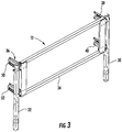
- An adjustable handrail panel 34 is operatively coupled to the stationary posts 30, 32 in a translatable manner. In particular, the adjustable handrail panel 34 is translatable between the first position ( FIG. 2 ) and the second position ( FIG. 3 ).
- the first position shown in FIG. 2 may be referred to as a normal operating position. This position is beneficial during normal movement of the elevator car 14. As shown, the adjustable handrail panel 34 has been translated to an inboard position of the region above the elevator car 14. This retracted position accommodates the clearance requirements described above. In particular, all portions of the adjustable handrail panel 34 are located flush with the side of the elevator car 14, or inboard thereof.
- the second position shown in FIG. 3 may be referred to as an equipment servicing position, or controller servicing position in such embodiments.
- the movement between the first and second positions is achieved by allowing the adjustable handrail panel 34 to be translatable perpendicularly relative to the first and second longitudinal axes and parallel to the top surface 15 of the elevator car 14.
- the adjustable handrail panel 34 is translatable toward and away from the first and second sides 24, 26 of the elevator car 14.
- the adjustable handrail panel 34 is at least flush with the side of the elevator car 14, or outboard thereof.
- FIGS. 4-6 the coupling, and sliding, relationship between the adjustable handrail panel 34 and the stationary posts is illustrated in greater detail.
- a single coupling between the adjustable handrail panel 34 and the first stationary post 32 is illustrated for purposes of description, but it is to be appreciated that an identical, mirrored-image, coupling is made between the adjustable handrail panel 34 and the second stationary post 30.
- At least one slide bracket 36 is provided to operatively couple the adjustable handrail panel 34 to the first stationary post 32.
- two slide brackets are illustrated to provide coupling that allows translation of the adjustable handrail panel 34.
- the slide bracket(s) 36 comprises a first slide bracket 38 and a second slide bracket 40.
- the first slide bracket 38 is fixedly coupled to the adjustable handrail panel 34 proximate a first end 42 of the first slide bracket 38.
- the second slide bracket 40 is also fixedly coupled to the adjustable handrail panel 34 proximate a first end 44 of the second slide bracket 40.
- first and second slide brackets 38, 40 are coupled to the adjustable handrail panel 34 proximate a top edge 46 and a bottom edge 48 of the adjustable handrail panel 34, respectively. Similar connections between a third slide bracket 50 and a fourth slide bracket 52 may be made with the adjustable handrail panel 34 to couple the panel 34 to the second stationary post 32.
- each of the at least one slide brackets 36 defines a slot 54 extending along a longitudinal direction of the bracket 36 from a first end 56 of the slot 54 to a second end 58 of the slot 54.
- the slot 54 is substantially straight along an entirety thereof.
- angled portions may be present at the first and/or second ends 56, 58 of the slot 54.
- a slide support pin 60 extends through the slot 54 and is fixedly secured to the first stationary post 30.
- an oversized head of the slide support pin 60 prevents complete insertion through the slot 54 and is in contact with an inner surface 62 of the slide bracket 36.
- a distal end of the slide support pin 60 extends through an aperture of the first stationary post 30 and is secured thereto with a nut 64 or the like to prevent withdrawal of the slide support pin 60 ( FIG. 4 and 6 ).
- the slide support pin 60 includes a threaded portion 68 to engage the nut 64 and a smooth portion 70 that is well-suited for repeated sliding engagement with slot walls 72 of the slide bracket 36 that define the slot 54.
- the smooth portion 70 may be made from, or coated with, a low friction material to enhance the above-described repeated sliding relative to the slot walls 72. Removal of the slide support pin 60 is not necessary to adjust the adjustable handrail panel 34 in a translatable manner.
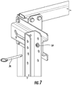
- a lock pin 74 is shown in a non-inserted condition ( FIG. 7 ) that corresponds to an unlocked condition of the adjustable handrail panel 34 and an inserted condition ( FIG. 8 ) that corresponds to a locked condition of the adjustable handrail panel 34.
- the lock pin 74 does not require threading in the illustrated embodiment. Rather, the lock pin 74 is simply inserted and removed in a repeatable manner into at least one aperture of the first stationary post 30 and/or the second stationary post 32 and the slide bracket 36 to lock and unlock the adjustable handrail panel 34 in the first or second position (and intermediate position(s) in some embodiments).
- the first stationary post 30 or the second stationary post 32 defines at least one aperture sized to receive the lock pin 74.
- Locking may be done by insertion of the lock pin 74 through only one of the stationary posts or may be done by insertion through both for redundancy purposes. Regardless of which stationary post the lock pin 74 is inserted through, the lock pin 74 is further inserted through one of a plurality of lock pin apertures 76 ( FIG. 5 ) defined by the slide bracket 36. In the illustrated embodiment of FIG. 5 , only two lock pin apertures 76 are defined to account for the two discrete positions of the adjustable handrail panel 34. In operation, the adjustable handrail panel 34 is translated to one of the discrete positions in the unlocked condition (i.e., lock pin 74 removed) and subsequently the lock pin 74 is re-inserted to lock the adjustable handrail panel 34 in the desired position.
- adjustment of the adjustable handrail system 12 is safe, simple and easily manageable by one person.
- the system 12 provides an adequate servicing zone when the elevator car 14 is disabled, while also being adjustable to provide required clearance between the handrails and adjacent hoistway mounted components and equipment while the elevator car is capable of moving within the hoistway.
- the system 12 does not require rotating, or collapsing, the handrail panel to an alternate position when servicing equipment.
- Such an open handrail panel leaves an unguarded portion of the hoistway, creating a fall hazard in some conditions.
- a non-rotatable handrail panel is provided to maintain a consistent handrail height and enclosure, while accommodating the above-described clearance requirements.
Landscapes
- Engineering & Computer Science (AREA)
- Civil Engineering (AREA)
- Mechanical Engineering (AREA)
- Structural Engineering (AREA)
- Cage And Drive Apparatuses For Elevators (AREA)
Abstract
Description
- The embodiments herein relate to elevator systems and, more particularly, to an adjustable handrail system for the top of an elevator car of such systems, as well as a method associated therewith.
- Elevator car roof railings typically are generally erected and/or folded by the operator standing on the car roof, so that the operator must take particular care to properly and safely fold the railing sides. One situation where the handrail is useful is while personnel are on top of the elevator car to access control equipment mounted in the hoistway.
- The handrail system may be erected into position, but when the operator has little work to do on the car roof, he may be tempted not to erect the railing and this is a hazardous situation. Alternatively, the handrail system may be erected with the ability to fold the handrail down, but it is difficult to provide a handrail that does not encroach into the prescribed minimum controller servicing zone due to limited available hoistway space. Therefore, providing a minimum clearance between handrail components and other elevator system components, while allowing an operator easy and safe access to hoistway mounted equipment is challenging to achieve in combination.
- According to one embodiment, an adjustable handrail system for a top region of an elevator car includes a first stationary post fixed to a top surface of the elevator car and extending upwardly therefrom along a first longitudinal axis. Also included is a second stationary post fixed to the top surface of the elevator car and extending upwardly therefrom along a second longitudinal axis, the first and second stationary posts spaced from each other and oriented parallel to each other. Further included is an adjustable handrail panel translatable between a first position and a second position, the adjustable handrail panel operatively coupled to the first stationary post and the second stationary post and translatable perpendicularly relative to the first and second longitudinal axes and parallel to the top surface of the elevator car.
- In addition to one or more of the features described above, or as an alternative, further embodiments may include a first slide bracket fixed to the adjustable handrail panel proximate a first end of the first slide bracket, the first slide bracket defining a first slot. Also included is a first slide support pin extending through the first slot and slidably disposed therein, the first slide support pin secured to the first stationary post to operatively couple the adjustable handrail panel to the first stationary post. Further included is a second slide bracket fixed to the adjustable handrail panel proximate a first end of the second slide bracket, the second slide bracket defining a second slot. Yet further included is a second slide support pin extending through the second slot and slidably disposed therein, the second slide support pin secured to the second stationary post to operatively couple the adjustable handrail panel to the second stationary post.
- In addition to one or more of the features described above, or as an alternative, further embodiments may include that the first slide bracket and the second slide bracket are each operatively coupled to the adjustable handrail panel proximate a top edge of the adjustable handrail panel. The adjustable handrail system may also include a third slide bracket fixed to the adjustable handrail panel proximate a first end of the third slide bracket and proximate a lower edge of the adjustable handrail panel, the third slide bracket defining a third slot. Further included is a third slide support pin extending through the third slot and slidably disposed therein, the third slide support pin secured to the first stationary post to operatively couple the adjustable handrail panel to the first stationary post. Yet further included is a fourth slide bracket fixed to the adjustable handrail panel proximate a first end of the fourth slide bracket and proximate a lower edge of the adjustable handrail panel, the fourth slide bracket defining a fourth slot. Also included is a fourth slide support pin extending through the fourth slot and slidably disposed therein, the fourth slide support pin secured to the second stationary post to operatively couple the adjustable handrail panel to the second stationary post.
- In addition to one or more of the features described above, or as an alternative, further embodiments may include a lock pin extendable through an aperture defined by one of the first stationary post and the second stationary post and through one of a plurality of slide bracket apertures defined by one of the first slide bracket and the second slide bracket, the lock pin fixing the adjustable handrail panel in the first position or the second position in an inserted condition.
- In addition to one or more of the features described above, or as an alternative, further embodiments may include that the adjustable handrail panel is not rotatable.
- In addition to one or more of the features described above, or as an alternative, further embodiments may include at least one intermediate position that the adjustable handrail may be translated to and fixed at, the at least one intermediate position located between the first position and the second position.
- In addition to one or more of the features described above, or as an alternative, further embodiments may include that the elevator car has a front side, a rear side, a first side and a second side, the adjustable handrail system disposed on the top surface of the elevator car and proximate the first side, the adjustable handrail panel translatable toward and away from the second side.
- In addition to one or more of the features described above, or as an alternative, further embodiments may include that the adjustable handrail system is translatable to access equipment mounted to a hoistway wall that the elevator car moves within.
- In addition to one or more of the features described above, or as an alternative, further embodiments may include that the equipment mounted to the hoistway wall is an elevator system controller.
- In addition to one or more of the features described above, or as an alternative, further embodiments may include that the first position of the adjustable handrail panel is a normal operating position and the second position is a controller servicing position.
- According to another embodiment, a method of adjusting a handrail panel on a top of an elevator car is provided. The method includes unlocking the handrail panel. The method also includes translating the handrail panel between a first position and a second position, the handrail panel operatively coupled to a first stationary post and a second stationary post, the first and second stationary posts each fixed to a top surface of the elevator car and extending upwardly therefrom along respective longitudinal axes, wherein translating the handrail panel is made perpendicularly relative to the first and second longitudinal axes.
- In addition to one or more of the features described above, or as an alternative, further embodiments may include that translating the handrail panel comprises sliding the handrail panel relative to the first and second stationary posts with a first slide bracket operatively coupling the handrail panel to the first stationary post and a second slide bracket operatively coupling the handrail panel to the second stationary post, the slide brackets each defining a respective slot having a slide pin disposed therein and secured to the respective stationary post, the slide pin slidable within the slot.
- In addition to one or more of the features described above, or as an alternative, further embodiments may include that unlocking the handrail panel comprises removing a repeatedly insertable lock pin through one of a plurality of apertures of one of the first and second stationary posts and through one of a plurality of apertures of the slide bracket.
- In addition to one or more of the features described above, or as an alternative, further embodiments may include that the handrail panel is adjustable to access an elevator system controller mounted to a hoistway wall of a hoistway that the elevator car moves within.
- In addition to one or more of the features described above, or as an alternative, further embodiments may include that the first position of the handrail panel is a normal operating position to provide clearance between the handrail panel and other components within the hoistway and the second position is a controller servicing position.
- The subject matter which is regarded as the disclosure is particularly pointed out and distinctly claimed in the claims at the conclusion of the specification. The foregoing and other features and advantages of the disclosure are apparent from the following detailed description taken in conjunction with the accompanying drawings in which:
-
FIG. 1 is a perspective view of a top region of an elevator car; -
FIG. 2 is a perspective view of an adjustable handrail system of the elevator car in a first position; -
FIG. 3 is a perspective view of the adjustable handrail system in a second position; -
FIG. 4 is a perspective view of a portion of the adjustable handrail system; -
FIG. 5 is a perspective view of a slide bracket of the adjustable handrail system; -
FIG. 6 is a perspective view of a slide support pin of the adjustable handrail system; -
FIG. 7 is a perspective view of a lock pin of the adjustable handrail system prior to engagement; and -
FIG. 8 is a perspective view of the lock pin in an engaged condition. - Referring to
FIG. 1 , a portion of an elevator system is illustrated and referenced generally withnumeral 10. The embodiments described herein relate to anadjustable handrail system 12 for anelevator car 14 of theelevator system 10. - The
elevator car 14 is moveable within ahoistway 16 defined byhoistway walls 18, as partially illustrated. Theadjustable handrail system 12 can be used with various types of elevator systems. For example, the embodiments described herein may be used with roped or ropeless elevator systems. Regardless of what type of elevator system theadjustable handrail system 12 is used with, thesystem 12 is disposed on a top region of theelevator car 14. In particular, theadjustable handrail system 12 is operatively coupled to, and extends upwardly from, atop surface 15 of theelevator car 14. As shown, theelevator car 14 includes a front side 22, arear side 20, afirst side 24 and asecond side 26. In the illustrated embodiment, theadjustable handrail system 12 extends along, and is disposed in close proximity to, thefirst side 24 of theelevator car 14. The embodiments of theadjustable handrail system 12 may be located on either thefirst side 24 or thesecond side 26. Additionally, thesystem 12 may be located on both thefirst side 24 and thesecond side 26. Thesystem 12, combined with other handrail features that may be fixed (i.e., non-moveable) form a space that is surrounded with a handrail structure surrounding the operator standing on theelevator car 14 for safety purposes. - As will be appreciated from the description herein, the
system 12 is translatable to allow an operator standing on atop surface 15 of the elevator car to simply slide a portion of theadjustable handrail system 12 between different positions for servicing purposes, while maintaining the top of thehandrail system 12 at a consistent height that is considered safe, thereby avoiding disadvantages associated with handrail systems that are collapsible or may be translated or rotated downwardly. While thehandrail system 12 is kept at the above-described consistent height, a specified clearance between the handrail system components and objects that theelevator car 14 will pass within thehoistway 16 during normal operation of theelevator car 14 is required. This clearance will vary depending upon the particular application. Therefore, thehandrail system 12 must be sufficiently "inboard" on theelevator car 14 to meet the clearance requirement, while also allowing an operator to conveniently access equipment mounted on one or more of thehoistway walls 18. For example, a system controller may be mounted in such a way that requires an operator to stand on thetop surface 15 of theelevator car 14 to perform required tasks with the equipment. The embodiments of theadjustable handrail system 12 described herein advantageously address the above-described issues, while conveniently maintaining the handrail system at a consistent height. - Referring now to
FIGS. 2 and3 , theadjustable handrail system 12 is illustrated in greater detail. Thesystem 12 includes a portion that is translatable between two discrete positions that are lockable, specifically a first position (FIG. 2 ) and a second position (FIG. 3 ). It is contemplated that theadjustable handrail system 12 may be translated, and locked, to one or more intermediate positions between the first position and the second position in some embodiments. Theadjustable handrail system 12 includes a firststationary post 30 fixed to thetop surface 15 of theelevator car 14 and extending upwardly therefrom along a first axis. Similarly, a secondstationary post 32 is fixed to thetop surface 15 and extends upwardly therefrom along a second axis. The first and secondstationary posts stationary posts top surface 15, as shown inFIG. 1 . Anadjustable handrail panel 34 is operatively coupled to thestationary posts adjustable handrail panel 34 is translatable between the first position (FIG. 2 ) and the second position (FIG. 3 ). - The first position shown in
FIG. 2 may be referred to as a normal operating position. This position is beneficial during normal movement of theelevator car 14. As shown, theadjustable handrail panel 34 has been translated to an inboard position of the region above theelevator car 14. This retracted position accommodates the clearance requirements described above. In particular, all portions of theadjustable handrail panel 34 are located flush with the side of theelevator car 14, or inboard thereof. - The second position shown in
FIG. 3 may be referred to as an equipment servicing position, or controller servicing position in such embodiments. The movement between the first and second positions is achieved by allowing theadjustable handrail panel 34 to be translatable perpendicularly relative to the first and second longitudinal axes and parallel to thetop surface 15 of theelevator car 14. In other words, theadjustable handrail panel 34 is translatable toward and away from the first andsecond sides elevator car 14. In the second position, theadjustable handrail panel 34 is at least flush with the side of theelevator car 14, or outboard thereof. - Referring now to
FIGS. 4-6 , the coupling, and sliding, relationship between theadjustable handrail panel 34 and the stationary posts is illustrated in greater detail. A single coupling between theadjustable handrail panel 34 and the firststationary post 32 is illustrated for purposes of description, but it is to be appreciated that an identical, mirrored-image, coupling is made between theadjustable handrail panel 34 and the secondstationary post 30. - At least one
slide bracket 36 is provided to operatively couple theadjustable handrail panel 34 to the firststationary post 32. In the illustrated embodiment, two slide brackets are illustrated to provide coupling that allows translation of theadjustable handrail panel 34. Specifically, the slide bracket(s) 36 comprises afirst slide bracket 38 and asecond slide bracket 40. Thefirst slide bracket 38 is fixedly coupled to theadjustable handrail panel 34 proximate afirst end 42 of thefirst slide bracket 38. Thesecond slide bracket 40 is also fixedly coupled to theadjustable handrail panel 34 proximate afirst end 44 of thesecond slide bracket 40. In some embodiments, such as that illustrated, the first andsecond slide brackets adjustable handrail panel 34 proximate atop edge 46 and abottom edge 48 of theadjustable handrail panel 34, respectively. Similar connections between athird slide bracket 50 and afourth slide bracket 52 may be made with theadjustable handrail panel 34 to couple thepanel 34 to the secondstationary post 32. - It is to be appreciated that a single slide panel may be provided at each end of the
adjustable handrail panel 34 to couple thepanel 34 to thestationary posts slide brackets 36 defines aslot 54 extending along a longitudinal direction of thebracket 36 from afirst end 56 of theslot 54 to asecond end 58 of theslot 54. In some embodiments, theslot 54 is substantially straight along an entirety thereof. Alternatively, as illustrated, angled portions may be present at the first and/or second ends 56, 58 of theslot 54. - A
slide support pin 60 extends through theslot 54 and is fixedly secured to the firststationary post 30. In particular, an oversized head of theslide support pin 60 prevents complete insertion through theslot 54 and is in contact with aninner surface 62 of theslide bracket 36. A distal end of theslide support pin 60 extends through an aperture of the firststationary post 30 and is secured thereto with anut 64 or the like to prevent withdrawal of the slide support pin 60 (FIG. 4 and6 ). As shown inFIG. 6 , theslide support pin 60 includes a threadedportion 68 to engage thenut 64 and asmooth portion 70 that is well-suited for repeated sliding engagement withslot walls 72 of theslide bracket 36 that define theslot 54. Thesmooth portion 70 may be made from, or coated with, a low friction material to enhance the above-described repeated sliding relative to theslot walls 72. Removal of theslide support pin 60 is not necessary to adjust theadjustable handrail panel 34 in a translatable manner. - Referring now to
FIGS. 7 and8 , alock pin 74 is shown in a non-inserted condition (FIG. 7 ) that corresponds to an unlocked condition of theadjustable handrail panel 34 and an inserted condition (FIG. 8 ) that corresponds to a locked condition of theadjustable handrail panel 34. Thelock pin 74 does not require threading in the illustrated embodiment. Rather, thelock pin 74 is simply inserted and removed in a repeatable manner into at least one aperture of the firststationary post 30 and/or the secondstationary post 32 and theslide bracket 36 to lock and unlock theadjustable handrail panel 34 in the first or second position (and intermediate position(s) in some embodiments). Specifically, the firststationary post 30 or the secondstationary post 32 defines at least one aperture sized to receive thelock pin 74. Locking may be done by insertion of thelock pin 74 through only one of the stationary posts or may be done by insertion through both for redundancy purposes. Regardless of which stationary post thelock pin 74 is inserted through, thelock pin 74 is further inserted through one of a plurality of lock pin apertures 76 (FIG. 5 ) defined by theslide bracket 36. In the illustrated embodiment ofFIG. 5 , only twolock pin apertures 76 are defined to account for the two discrete positions of theadjustable handrail panel 34. In operation, theadjustable handrail panel 34 is translated to one of the discrete positions in the unlocked condition (i.e.,lock pin 74 removed) and subsequently thelock pin 74 is re-inserted to lock theadjustable handrail panel 34 in the desired position. - Advantageously, adjustment of the
adjustable handrail system 12 is safe, simple and easily manageable by one person. Thesystem 12 provides an adequate servicing zone when theelevator car 14 is disabled, while also being adjustable to provide required clearance between the handrails and adjacent hoistway mounted components and equipment while the elevator car is capable of moving within the hoistway. Additionally, thesystem 12 does not require rotating, or collapsing, the handrail panel to an alternate position when servicing equipment. Such an open handrail panel leaves an unguarded portion of the hoistway, creating a fall hazard in some conditions. In the embodiments described herein, a non-rotatable handrail panel is provided to maintain a consistent handrail height and enclosure, while accommodating the above-described clearance requirements. - While the disclosure has been described in detail in connection with only a limited number of embodiments, it should be readily understood that the disclosure is not limited to such disclosed embodiments. Rather, the disclosure can be modified to incorporate any number of variations, alterations, substitutions or equivalent arrangements not heretofore described, but which are commensurate with the spirit and scope of the disclosure. Additionally, while various embodiments of the disclosure have been described, it is to be understood that aspects of the disclosure may include only some of the described embodiments. Accordingly, the disclosure is not to be seen as limited by the foregoing description, but is only limited by the scope of the appended claims.
Claims (15)
- An adjustable handrail system for a top region of an elevator car comprising:a first stationary post fixed to a top surface of the elevator car and extending upwardly therefrom along a first longitudinal axis;a second stationary post fixed to the top surface of the elevator car and extending upwardly therefrom along a second longitudinal axis, the first and second stationary posts spaced from each other and oriented parallel to each other; andan adjustable handrail panel translatable between a first position and a second position, the adjustable handrail panel operatively coupled to the first stationary post and the second stationary post and translatable perpendicularly relative to the first and second longitudinal axes and parallel to the top surface of the elevator car.
- The adjustable handrail system of claim 1, further comprising:a first slide bracket fixed to the adjustable handrail panel proximate a first end of the first slide bracket, the first slide bracket defining a first slot;a first slide support pin extending through the first slot and slidably disposed therein, the first slide support pin secured to the first stationary post to operatively couple the adjustable handrail panel to the first stationary post;a second slide bracket fixed to the adjustable handrail panel proximate a first end of the second slide bracket, the second slide bracket defining a second slot; anda second slide support pin extending through the second slot and slidably disposed therein, the second slide support pin secured to the second stationary post to operatively couple the adjustable handrail panel to the second stationary post.
- The adjustable handrail system of claim 2, wherein the first slide bracket and the second slide bracket are each operatively coupled to the adjustable handrail panel proximate a top edge of the adjustable handrail panel, the adjustable handrail system further comprising:a third slide bracket fixed to the adjustable handrail panel proximate a first end of the third slide bracket and proximate a lower edge of the adjustable handrail panel, the third slide bracket defining a third slot;a third slide support pin extending through the third slot and slidably disposed therein, the third slide support pin secured to the first stationary post to operatively couple the adjustable handrail panel to the first stationary post;a fourth slide bracket fixed to the adjustable handrail panel proximate a first end of the fourth slide bracket and proximate a lower edge of the adjustable handrail panel, the fourth slide bracket defining a fourth slot; anda fourth slide support pin extending through the fourth slot and slidably disposed therein, the fourth slide support pin secured to the second stationary post to operatively couple the adjustable handrail panel to the second stationary post.
- The adjustable handrail system of claim 2 or 3, further comprising a lock pin extendable through an aperture defined by one of the first stationary post and the second stationary post and through one of a plurality of slide bracket apertures defined by one of the first slide bracket and the second slide bracket, the lock pin fixing the adjustable handrail panel in the first position or the second position in an inserted condition.
- The adjustable handrail system of any of the preceding claims, wherein the adjustable handrail panel is not rotatable.
- The adjustable handrail system of any of the preceding claims, further comprising at least one intermediate position that the adjustable handrail may be translated to and fixed at, the at least one intermediate position located between the first position and the second position.
- The adjustable handrail system of any of the preceding claims, wherein the elevator car has a front side, a rear side, a first side and a second side, the adjustable handrail system disposed on the top surface of the elevator car and proximate the first side, the adjustable handrail panel translatable toward and away from the second side.
- The adjustable handrail system of any of the preceding claims, wherein the adjustable handrail system is translatable to access equipment mounted to a hoistway wall that the elevator car moves within.
- The adjustable handrail system of claim 8, wherein the equipment mounted to the hoistway wall is an elevator system controller.
- The adjustable handrail system of claim 9, wherein the first position of the adjustable handrail panel is a normal operating position and the second position is a controller servicing position.
- A method of adjusting a handrail panel on a top of an elevator car comprising:unlocking the handrail panel; andtranslating the handrail panel between a first position and a second position, the handrail panel operatively coupled to a first stationary post and a second stationary post, the first and second stationary posts each fixed to a top surface of the elevator car and extending upwardly therefrom along respective longitudinal axes, wherein translating the handrail panel is made perpendicularly relative to the first and second longitudinal axes.
- The method of claim 11, wherein translating the handrail panel comprises sliding the handrail panel relative to the first and second stationary posts with a first slide bracket operatively coupling the handrail panel to the first stationary post and a second slide bracket operatively coupling the handrail panel to the second stationary post, the slide brackets each defining a respective slot having a slide pin disposed therein and secured to the respective stationary post, the slide pin slidable within the slot.
- The method of claim 12, wherein unlocking the handrail panel comprises removing a repeatedly insertable lock pin through one of a plurality of apertures of one of the first and second stationary posts and through one of a plurality of apertures of the slide bracket.
- The method of any of claims 11-13, wherein the handrail panel is adjustable to access an elevator system controller mounted to a hoistway wall of a hoistway that the elevator car moves within.
- The method of claim 14, wherein the first position of the handrail panel is a normal operating position to provide clearance between the handrail panel and other components within the hoistway and the second position is a controller servicing position.
Applications Claiming Priority (1)
| Application Number | Priority Date | Filing Date | Title |
|---|---|---|---|
| US201662356224P | 2016-06-29 | 2016-06-29 |
Publications (1)
| Publication Number | Publication Date |
|---|---|
| EP3263503A1 true EP3263503A1 (en) | 2018-01-03 |
Family
ID=59258073
Family Applications (1)
| Application Number | Title | Priority Date | Filing Date |
|---|---|---|---|
| EP17178680.9A Withdrawn EP3263503A1 (en) | 2016-06-29 | 2017-06-29 | Adjustable handrail system for a top of an elevator car and method of adjusting |
Country Status (4)
| Country | Link |
|---|---|
| US (1) | US20180002139A1 (en) |
| EP (1) | EP3263503A1 (en) |
| KR (1) | KR20180002510A (en) |
| CN (1) | CN107539851A (en) |
Cited By (2)
| Publication number | Priority date | Publication date | Assignee | Title |
|---|---|---|---|---|
| CN109110632A (en) * | 2018-10-31 | 2019-01-01 | 布劳恩电梯有限公司 | Escalator subsection safe transportation connection support bracket |
| CN109368450A (en) * | 2018-11-23 | 2019-02-22 | 巨龙电梯有限公司 | A kind of car top guard of telescopic folding |
Families Citing this family (11)
| Publication number | Priority date | Publication date | Assignee | Title |
|---|---|---|---|---|
| JP6366847B2 (en) * | 2015-07-23 | 2018-08-01 | 三菱電機株式会社 | Elevator car handrail device |
| MY190801A (en) * | 2015-09-30 | 2022-05-12 | Inventio Ag | Lift system |
| US10836605B2 (en) * | 2015-12-18 | 2020-11-17 | Inventio Ag | Elevator car with a foldable balustrade and control device for an elevator installation having such an elevator car |
| CN109963804B (en) * | 2016-11-15 | 2021-10-12 | 因温特奥股份公司 | Elevator cage |
| JP6968030B2 (en) * | 2018-05-17 | 2021-11-17 | 三菱電機ビルテクノサービス株式会社 | Elevator car safety fence |
| US11453987B2 (en) | 2018-05-31 | 2022-09-27 | Universal City Studios Llc | Movable barrier for walkway |
| CN108439154A (en) * | 2018-06-12 | 2018-08-24 | 许昌昌信机械制造有限公司 | A kind of home lift Multifunction armrests |
| CN111362085B (en) * | 2018-12-26 | 2022-12-20 | 奥的斯电梯公司 | Railing subassembly, car and elevator |
| WO2021121904A1 (en) * | 2019-12-20 | 2021-06-24 | Inventio Ag | Elevator car pivotable balustrade and maintenance method for an elevator |
| US12522470B2 (en) * | 2022-02-09 | 2026-01-13 | Inventio Ag | Elevator system |
| JPWO2024180586A1 (en) * | 2023-02-27 | 2024-09-06 |
Citations (4)
| Publication number | Priority date | Publication date | Assignee | Title |
|---|---|---|---|---|
| GB505240A (en) * | 1938-03-15 | 1939-05-08 | Charles Such | Improvements in safety guards for collapsible gates |
| US5531159A (en) * | 1994-08-19 | 1996-07-02 | Universal Display & Fixtures Company | Pull-out drop down shelf structure |
| WO2004000713A1 (en) * | 2002-06-20 | 2003-12-31 | Otis Elevator Company | Safety top balustrade for a car of a machine room-less elevator |
| EP1481936A1 (en) * | 2002-03-07 | 2004-12-01 | Mitsubishi Denki Kabushiki Kaisha | Handrail above cage of elevator |
Family Cites Families (9)
| Publication number | Priority date | Publication date | Assignee | Title |
|---|---|---|---|---|
| CN2803989Y (en) * | 2005-06-30 | 2006-08-09 | 扬州通利冷藏集装箱有限公司 | Contracting fender of container top |
| EP2138440A4 (en) * | 2007-04-26 | 2013-10-30 | Mitsubishi Electric Corp | RAMP DEVICE ON AN ELEVATOR CAB |
| US8215619B2 (en) * | 2009-03-31 | 2012-07-10 | Energy Absorption Systems, Inc. | Guardrail assembly, breakaway support post for a guardrail and methods for the assembly and use thereof |
| CN201580873U (en) * | 2010-01-21 | 2010-09-15 | 张恒亮 | Guard rail for mouth of elevator hoistway |
| CN103420256B (en) * | 2012-05-23 | 2016-05-18 | 株式会社日立建筑系统 | Lift car upper handrail device and elevator car compartment handle method to set up |
| CN202897739U (en) * | 2012-11-09 | 2013-04-24 | 江南嘉捷电梯股份有限公司 | Rotating elevator top guardrail |
| CN203238976U (en) * | 2013-05-16 | 2013-10-16 | 江苏省苏中建设集团股份有限公司 | Elevator shaft protective handrail |
| CN203271166U (en) * | 2013-05-30 | 2013-11-06 | 安徽天成建设有限公司 | Temporary protective guard for elevator shaft door opening |
| CN204096853U (en) * | 2014-09-16 | 2015-01-14 | 深圳亚洲富士电梯设备有限公司 | elevator car top guardrail and elevator |
-
2017
- 2017-06-21 KR KR1020170078448A patent/KR20180002510A/en not_active Withdrawn
- 2017-06-26 US US15/633,151 patent/US20180002139A1/en not_active Abandoned
- 2017-06-28 CN CN201710511594.6A patent/CN107539851A/en active Pending
- 2017-06-29 EP EP17178680.9A patent/EP3263503A1/en not_active Withdrawn
Patent Citations (4)
| Publication number | Priority date | Publication date | Assignee | Title |
|---|---|---|---|---|
| GB505240A (en) * | 1938-03-15 | 1939-05-08 | Charles Such | Improvements in safety guards for collapsible gates |
| US5531159A (en) * | 1994-08-19 | 1996-07-02 | Universal Display & Fixtures Company | Pull-out drop down shelf structure |
| EP1481936A1 (en) * | 2002-03-07 | 2004-12-01 | Mitsubishi Denki Kabushiki Kaisha | Handrail above cage of elevator |
| WO2004000713A1 (en) * | 2002-06-20 | 2003-12-31 | Otis Elevator Company | Safety top balustrade for a car of a machine room-less elevator |
Cited By (3)
| Publication number | Priority date | Publication date | Assignee | Title |
|---|---|---|---|---|
| CN109110632A (en) * | 2018-10-31 | 2019-01-01 | 布劳恩电梯有限公司 | Escalator subsection safe transportation connection support bracket |
| CN109368450A (en) * | 2018-11-23 | 2019-02-22 | 巨龙电梯有限公司 | A kind of car top guard of telescopic folding |
| CN109368450B (en) * | 2018-11-23 | 2024-03-19 | 巨龙电梯有限公司 | Telescopic folding car roof guardrail |
Also Published As
| Publication number | Publication date |
|---|---|
| CN107539851A (en) | 2018-01-05 |
| KR20180002510A (en) | 2018-01-08 |
| US20180002139A1 (en) | 2018-01-04 |
Similar Documents
| Publication | Publication Date | Title |
|---|---|---|
| US20180002139A1 (en) | Adjustable handrail system for a top of an elevator car and method of adjusting | |
| EP3995665B1 (en) | Platform ladder apparatus | |
| US20080217113A1 (en) | Roof Railing For an Elevator Car Adapted to Be Collapsed With a Handle Actuating All Sides at the Same Time | |
| EP3541734B2 (en) | Elevator car | |
| EP3819249B1 (en) | Elevator car | |
| CN100564224C (en) | The safety top guardrail that is used for the car of machine-roomless lift | |
| EP3512796B1 (en) | Elevator car with a working platform | |
| US20210061616A1 (en) | Low overhead compensatory measure | |
| EP3292062A1 (en) | Apparatus and method for adjusting landing door locks from inside an elevator car | |
| EP1050504B1 (en) | Device for carrying out work in an elevator shaft | |
| US20210238009A1 (en) | Elevator car with moving emergency stop device | |
| EP2353564B1 (en) | Wheelchair holder for vehicles | |
| KR101805401B1 (en) | Standard Platform for Aircraft | |
| EP3247664B1 (en) | Elevator | |
| EP1988049A1 (en) | Safety device for an elevator car | |
| WO2018016032A1 (en) | Elevator | |
| EP4286314A1 (en) | Elevator car with blocking member for foldable working platform | |
| EP3356272B1 (en) | Elevator system | |
| EP3929136B1 (en) | Hoistway access ladder storage | |
| KR20170064708A (en) | Separation protection device of work safety railings | |
| CN104418199B (en) | Lift appliance and its operation table apparatus | |
| DE112016007151B4 (en) | Cabin roof railing - elevator device | |
| CN114698927A (en) | Lifting device | |
| WO2017072255A1 (en) | Maintenance platform for an elevator cab | |
| CN1068295A (en) | Anti-fall safty device on table of printing machine |
Legal Events
| Date | Code | Title | Description |
|---|---|---|---|
| PUAI | Public reference made under article 153(3) epc to a published international application that has entered the european phase |
Free format text: ORIGINAL CODE: 0009012 |
|
| STAA | Information on the status of an ep patent application or granted ep patent |
Free format text: STATUS: THE APPLICATION HAS BEEN PUBLISHED |
|
| AK | Designated contracting states |
Kind code of ref document: A1 Designated state(s): AL AT BE BG CH CY CZ DE DK EE ES FI FR GB GR HR HU IE IS IT LI LT LU LV MC MK MT NL NO PL PT RO RS SE SI SK SM TR |
|
| AX | Request for extension of the european patent |
Extension state: BA ME |
|
| STAA | Information on the status of an ep patent application or granted ep patent |
Free format text: STATUS: REQUEST FOR EXAMINATION WAS MADE |
|
| 17P | Request for examination filed |
Effective date: 20180703 |
|
| RBV | Designated contracting states (corrected) |
Designated state(s): AL AT BE BG CH CY CZ DE DK EE ES FI FR GB GR HR HU IE IS IT LI LT LU LV MC MK MT NL NO PL PT RO RS SE SI SK SM TR |
|
| STAA | Information on the status of an ep patent application or granted ep patent |
Free format text: STATUS: EXAMINATION IS IN PROGRESS |
|
| 17Q | First examination report despatched |
Effective date: 20190816 |
|
| STAA | Information on the status of an ep patent application or granted ep patent |
Free format text: STATUS: THE APPLICATION IS DEEMED TO BE WITHDRAWN |
|
| 18D | Application deemed to be withdrawn |
Effective date: 20200103 |