EP3263380A1 - Transmission apparatus for an automated manual transmission, power unit and the related vehicle comprising said apparatus - Google Patents
Transmission apparatus for an automated manual transmission, power unit and the related vehicle comprising said apparatus Download PDFInfo
- Publication number
- EP3263380A1 EP3263380A1 EP17176968.0A EP17176968A EP3263380A1 EP 3263380 A1 EP3263380 A1 EP 3263380A1 EP 17176968 A EP17176968 A EP 17176968A EP 3263380 A1 EP3263380 A1 EP 3263380A1
- Authority
- EP
- European Patent Office
- Prior art keywords
- transmission
- auxiliary
- shaft
- automated manual
- manual transmission
- Prior art date
- Legal status (The legal status is an assumption and is not a legal conclusion. Google has not performed a legal analysis and makes no representation as to the accuracy of the status listed.)
- Granted
Links
Images
Classifications
-
- B—PERFORMING OPERATIONS; TRANSPORTING
- B60—VEHICLES IN GENERAL
- B60K—ARRANGEMENT OR MOUNTING OF PROPULSION UNITS OR OF TRANSMISSIONS IN VEHICLES; ARRANGEMENT OR MOUNTING OF PLURAL DIVERSE PRIME-MOVERS IN VEHICLES; AUXILIARY DRIVES FOR VEHICLES; INSTRUMENTATION OR DASHBOARDS FOR VEHICLES; ARRANGEMENTS IN CONNECTION WITH COOLING, AIR INTAKE, GAS EXHAUST OR FUEL SUPPLY OF PROPULSION UNITS IN VEHICLES
- B60K6/00—Arrangement or mounting of plural diverse prime-movers for mutual or common propulsion, e.g. hybrid propulsion systems comprising electric motors and internal combustion engines
- B60K6/20—Arrangement or mounting of plural diverse prime-movers for mutual or common propulsion, e.g. hybrid propulsion systems comprising electric motors and internal combustion engines the prime-movers consisting of electric motors and internal combustion engines, e.g. HEVs
- B60K6/42—Arrangement or mounting of plural diverse prime-movers for mutual or common propulsion, e.g. hybrid propulsion systems comprising electric motors and internal combustion engines the prime-movers consisting of electric motors and internal combustion engines, e.g. HEVs characterised by the architecture of the hybrid electric vehicle
- B60K6/48—Parallel type
-
- B—PERFORMING OPERATIONS; TRANSPORTING
- B60—VEHICLES IN GENERAL
- B60K—ARRANGEMENT OR MOUNTING OF PROPULSION UNITS OR OF TRANSMISSIONS IN VEHICLES; ARRANGEMENT OR MOUNTING OF PLURAL DIVERSE PRIME-MOVERS IN VEHICLES; AUXILIARY DRIVES FOR VEHICLES; INSTRUMENTATION OR DASHBOARDS FOR VEHICLES; ARRANGEMENTS IN CONNECTION WITH COOLING, AIR INTAKE, GAS EXHAUST OR FUEL SUPPLY OF PROPULSION UNITS IN VEHICLES
- B60K6/00—Arrangement or mounting of plural diverse prime-movers for mutual or common propulsion, e.g. hybrid propulsion systems comprising electric motors and internal combustion engines
- B60K6/20—Arrangement or mounting of plural diverse prime-movers for mutual or common propulsion, e.g. hybrid propulsion systems comprising electric motors and internal combustion engines the prime-movers consisting of electric motors and internal combustion engines, e.g. HEVs
- B60K6/22—Arrangement or mounting of plural diverse prime-movers for mutual or common propulsion, e.g. hybrid propulsion systems comprising electric motors and internal combustion engines the prime-movers consisting of electric motors and internal combustion engines, e.g. HEVs characterised by apparatus, components or means specially adapted for HEVs
- B60K6/38—Arrangement or mounting of plural diverse prime-movers for mutual or common propulsion, e.g. hybrid propulsion systems comprising electric motors and internal combustion engines the prime-movers consisting of electric motors and internal combustion engines, e.g. HEVs characterised by apparatus, components or means specially adapted for HEVs characterised by the driveline clutches
- B60K6/383—One-way clutches or freewheel devices
-
- B—PERFORMING OPERATIONS; TRANSPORTING
- B60—VEHICLES IN GENERAL
- B60K—ARRANGEMENT OR MOUNTING OF PROPULSION UNITS OR OF TRANSMISSIONS IN VEHICLES; ARRANGEMENT OR MOUNTING OF PLURAL DIVERSE PRIME-MOVERS IN VEHICLES; AUXILIARY DRIVES FOR VEHICLES; INSTRUMENTATION OR DASHBOARDS FOR VEHICLES; ARRANGEMENTS IN CONNECTION WITH COOLING, AIR INTAKE, GAS EXHAUST OR FUEL SUPPLY OF PROPULSION UNITS IN VEHICLES
- B60K6/00—Arrangement or mounting of plural diverse prime-movers for mutual or common propulsion, e.g. hybrid propulsion systems comprising electric motors and internal combustion engines
- B60K6/20—Arrangement or mounting of plural diverse prime-movers for mutual or common propulsion, e.g. hybrid propulsion systems comprising electric motors and internal combustion engines the prime-movers consisting of electric motors and internal combustion engines, e.g. HEVs
- B60K6/42—Arrangement or mounting of plural diverse prime-movers for mutual or common propulsion, e.g. hybrid propulsion systems comprising electric motors and internal combustion engines the prime-movers consisting of electric motors and internal combustion engines, e.g. HEVs characterised by the architecture of the hybrid electric vehicle
- B60K6/48—Parallel type
- B60K2006/4808—Electric machine connected or connectable to gearbox output shaft
-
- B—PERFORMING OPERATIONS; TRANSPORTING
- B60—VEHICLES IN GENERAL
- B60K—ARRANGEMENT OR MOUNTING OF PROPULSION UNITS OR OF TRANSMISSIONS IN VEHICLES; ARRANGEMENT OR MOUNTING OF PLURAL DIVERSE PRIME-MOVERS IN VEHICLES; AUXILIARY DRIVES FOR VEHICLES; INSTRUMENTATION OR DASHBOARDS FOR VEHICLES; ARRANGEMENTS IN CONNECTION WITH COOLING, AIR INTAKE, GAS EXHAUST OR FUEL SUPPLY OF PROPULSION UNITS IN VEHICLES
- B60K6/00—Arrangement or mounting of plural diverse prime-movers for mutual or common propulsion, e.g. hybrid propulsion systems comprising electric motors and internal combustion engines
- B60K6/20—Arrangement or mounting of plural diverse prime-movers for mutual or common propulsion, e.g. hybrid propulsion systems comprising electric motors and internal combustion engines the prime-movers consisting of electric motors and internal combustion engines, e.g. HEVs
- B60K6/42—Arrangement or mounting of plural diverse prime-movers for mutual or common propulsion, e.g. hybrid propulsion systems comprising electric motors and internal combustion engines the prime-movers consisting of electric motors and internal combustion engines, e.g. HEVs characterised by the architecture of the hybrid electric vehicle
- B60K6/48—Parallel type
- B60K2006/4825—Electric machine connected or connectable to gearbox input shaft
-
- B—PERFORMING OPERATIONS; TRANSPORTING
- B60—VEHICLES IN GENERAL
- B60K—ARRANGEMENT OR MOUNTING OF PROPULSION UNITS OR OF TRANSMISSIONS IN VEHICLES; ARRANGEMENT OR MOUNTING OF PLURAL DIVERSE PRIME-MOVERS IN VEHICLES; AUXILIARY DRIVES FOR VEHICLES; INSTRUMENTATION OR DASHBOARDS FOR VEHICLES; ARRANGEMENTS IN CONNECTION WITH COOLING, AIR INTAKE, GAS EXHAUST OR FUEL SUPPLY OF PROPULSION UNITS IN VEHICLES
- B60K6/00—Arrangement or mounting of plural diverse prime-movers for mutual or common propulsion, e.g. hybrid propulsion systems comprising electric motors and internal combustion engines
- B60K6/20—Arrangement or mounting of plural diverse prime-movers for mutual or common propulsion, e.g. hybrid propulsion systems comprising electric motors and internal combustion engines the prime-movers consisting of electric motors and internal combustion engines, e.g. HEVs
- B60K6/42—Arrangement or mounting of plural diverse prime-movers for mutual or common propulsion, e.g. hybrid propulsion systems comprising electric motors and internal combustion engines the prime-movers consisting of electric motors and internal combustion engines, e.g. HEVs characterised by the architecture of the hybrid electric vehicle
- B60K6/48—Parallel type
- B60K2006/4833—Step up or reduction gearing driving generator, e.g. to operate generator in most efficient speed range
-
- Y—GENERAL TAGGING OF NEW TECHNOLOGICAL DEVELOPMENTS; GENERAL TAGGING OF CROSS-SECTIONAL TECHNOLOGIES SPANNING OVER SEVERAL SECTIONS OF THE IPC; TECHNICAL SUBJECTS COVERED BY FORMER USPC CROSS-REFERENCE ART COLLECTIONS [XRACs] AND DIGESTS
- Y02—TECHNOLOGIES OR APPLICATIONS FOR MITIGATION OR ADAPTATION AGAINST CLIMATE CHANGE
- Y02T—CLIMATE CHANGE MITIGATION TECHNOLOGIES RELATED TO TRANSPORTATION
- Y02T10/00—Road transport of goods or passengers
- Y02T10/60—Other road transportation technologies with climate change mitigation effect
- Y02T10/62—Hybrid vehicles
Definitions
- the present invention relates to a transmission apparatus for vehicles equipped with an automated manual transmission (AMT), a power unit and a related vehicle equipped with said transmission apparatus.
- the vehicles may be either hybrid vehicles (HEVs), equipped with an internal combustion engine and an electric motor, or electric vehicles (BEVs).
- HEVs hybrid vehicles
- BEVs electric vehicles
- the gear change phase is not optimized, since the user is able to clearly notice a torque gap due to the disengagement and subsequent engagement of the transmission.
- auxiliary electric machine that provides torque to the wheels so as to fill the torque gap which otherwise would be noticed during the gear shift phase in an automated manual transmission.
- Said auxiliary electric machine may also be used for other purposes.
- the auxiliary electric machine may allow the vehicle to run fully in electric mode or even only when reversing.
- the same auxiliary electric machine may be properly connected upstream from the transmission so as to enable the startup function of the internal combustion engine upon disconnection of the transmission, but also to have a rapid synchronization of the transmission during the gear change phase, with particular reference to the downshift phase.
- auxiliary electric machine may be used to assist the operation of the internal combustion engine, for example during the release phase of the accelerator, in order to reduce fuel consumption or even to increase its performance or, for example, to overcome the delayed response, so-called 'turbo-lag', typical of supercharged engines.
- the auxiliary unit In order to optimize the overall operation of the transmission and the internal combustion engine, the auxiliary unit must be frequently and repeatedly connected both upstream and downstream of the transmission, depending on the function to be performed and the contingent operating conditions of the vehicle, which may depend both on the vehicle's route and the driving and traffic conditions.
- AMT automated manual transmission 12
- the type of internal combustion engine used in the power unit is not indicated, meaning any type of internal combustion engine, both in the Otto cycle and in the diesel cycle.
- the internal combustion engine 16 has a drive shaft which may be mechanically connected to an input shaft of the transmission apparatus 8 by means of a clutch 20, in a known manner.
- the transmission apparatus 8 comprises the automated manual transmission 12, equipped with an input shaft 24 and an output shaft 28.
- the input shaft 24, as seen, is configured to be selectively connected to the internal combustion engine 16, for example by means of said clutch 20.
- the output shaft 28 is configured in a manner to be mechanically connected to at least one drive wheel 32 of a vehicle.
- the transmission apparatus 8 further comprises an auxiliary electric machine 36 having an auxiliary shaft 40 and an auxiliary transmission 44 selectively connectable to the input shaft 24 and/or to the output shaft 28 of the automated manual transmission 12.
- the auxiliary electric machine 36 is an electric machine that may operate both as a motor and a generator to provide torque as needed and to generate electric power, for example during the braking or release phase, as better described below.
- the auxiliary transmission 44 comprises a single transmission selector 48 movable in three positions, wherein:
- said single transmission selector 48 is movable along an actuating stroke between said first, second and third positions.
- said single transmission selector 48 is movable along an axial actuating stroke 52, wherein said first and third positions are located at respective end strokes of the axial actuating stroke 52, and wherein said second position is intermediate or interposed between said end strokes.
- said single transmission selector 48 comprises a slider 56, movable between said first, second and third positions, the slider 56 being equipped with a pair of gears 60 suitable to engage and disengage with the corresponding first and second mechanical elements 64, 68 operatively connected to the input shaft 24 and the output shaft 28 respectively.
- said gears 60 comprise frontal-engagement gears suitable to mesh with the corresponding first and second mechanical elements 64, 68 operatively connected to the input shaft 24 and to the output shaft 28 respectively in the first and in the third engagement positions.
- the front engagements allow the engagement in a direction of engagement parallel to said axial actuating stroke 52.
- the auxiliary transmission 44 comprises at least a first auxiliary shaft 72 and a second auxiliary shaft 76, wherein the first auxiliary shaft 72 is integral in rotation with the first mechanical element 64 and the second auxiliary shaft 76 is integral in rotation with the second mechanical element 68.
- Said single transmission selector 48 comprises an actuator that moves it to said three positions; the transmission apparatus 8 comprises a processing and control unit (not shown) which controls the actuator of the transmission selector 48 and the automated manual transmission 12.
- auxiliary shaft 40 of the auxiliary electric machine 36 is mechanically disconnected from the input 24 and output 28 shafts.
- both the internal combustion engine 16 and the automated manual transmission 12 work without receiving any auxiliary power from the auxiliary electric machine 36 which is unable to provide torque, operating as a motor, nor to receive torque, operating as a generator.
- the vehicle may pass into the first upstream engagement condition ( figure 4 ), wherein a mechanical connection is made between the auxiliary shaft 40 of the auxiliary electric machine 36 and the input shaft 24.
- a mechanical connection is made between the auxiliary shaft 40 of the auxiliary electric machine 36 and the input shaft 24.
- Such condition is obtained by actuating the transmission selector 48 which, translating in the axial actuating stroke 52, makes the mechanical connection between the auxiliary electric machine 36 and the input shaft 24 by mechanical coupling between the gearing 60 and the first mechanical element 64.
- the vehicle may pass into the third upstream engagement condition ( figure 5 ), wherein a mechanical connection is made between the auxiliary shaft 40 of the auxiliary electric machine 36 and the output shaft 28.
- a mechanical connection is made between the auxiliary shaft 40 of the auxiliary electric machine 36 and the output shaft 28.
- Such condition is obtained by actuating the transmission selector 48 which, translating in the axial actuating stroke 52, makes the mechanical connection between the auxiliary electric machine 36 and the output shaft 28 by mechanical coupling between the gearing 60 and the second mechanical element 68.
- torque at the output of the automated manual transmission 12 for example to cover a torque gap, or to achieve a regenerative braking or to provide additional torque to the internal combustion engine 16.
- the transmission apparatus for vehicles equipped with an automated manual transmission according to the invention allows the disadvantages presented in the prior art to be overcome.
- the transmission apparatus allows the auxiliary electric machine to be connected repeatedly and alternatively to the transmission in a quick, efficient and reliable manner.
- the transmission apparatus does not cause a significant increase in mass and bulk of the transmission, unlike known solutions.
- the present invention allows one to obtain all the functions necessary to optimize the transmission's operation, the fuel consumption and driving sensation of the vehicle with which it is provided, e.g.: transmission in exclusively electrical mode, startup of the internal combustion engine, torque gap filling during gear shifting, energy savings in the torque release phase (sailing), regenerative braking for recharging the battery pack, overboost both to increase performance in general and to compensate for the turbo lag of the possible overcharging of the internal combustion engine.
- All of these functions may be obtained through a suitable and continuous strategy for connecting and disconnecting the auxiliary unit from the transmission apparatus in a fast and reliable manner.
- Such a strategy includes the mechanical disconnection of the auxiliary unit from the transmission, when no intervention of the auxiliary unit is required in order to avoid dragging inertia as well as the mechanical connection of the auxiliary unit upstream or downstream of the transmission as a function of the driver's needs, of the battery pack charging status, and the conditions of the route followed by the vehicle.
- Connection and disconnection through the use of a single selector is particularly fast, precise and reliable. It also simplifies management and control of the transmission since each position of the single transmission selector, i.e. the disengagement, the upstream engagement of the transmission and the downstream engagement of the transmission, allows a single possible condition of operation, automatically excluding the others.
- the operations of the actuator may also be on the order of dozens per minute and always need to ensure the reliability of the transmission management.
- the present invention is particularly suitable to be optimized by adapting automatically to the route to be followed with the vehicle, depending on the contingent position of the vehicle itself.
- the vehicle is following a predetermined route, for example, one set in a satellite navigator that the vehicle is equipped with, at any moment, and in advance, it is possible to know and predict the type of route the vehicle will have to follow, estimating the speed but also the demand for torque due, for example, to the possible gradient of the road segment.
- a predetermined route for example, one set in a satellite navigator that the vehicle is equipped with, at any moment, and in advance
- this type of transmission apparatus management is also possible without a predetermined route to be followed, since, due to the GPS, it is possible to know the instantaneous position of the vehicle and the gradient of the road section that is being traveled on or that one is presumably faced with and so on.
- This optimized management of the transmission apparatus allows a reduction of the vehicle's fuel consumption to be calibrated specifically as a function of the route taken, for example, to favor electric traction and recovery of kinetic energy during the release and/or braking phase.
Landscapes
- Engineering & Computer Science (AREA)
- Chemical & Material Sciences (AREA)
- Combustion & Propulsion (AREA)
- Transportation (AREA)
- Mechanical Engineering (AREA)
- Hybrid Electric Vehicles (AREA)
- Electric Propulsion And Braking For Vehicles (AREA)
- Structure Of Transmissions (AREA)
- Arrangement Of Transmissions (AREA)
- Gear-Shifting Mechanisms (AREA)
Abstract
- in a first upstream engagement position, a mechanical connection is made between the auxiliary shaft (40) of the auxiliary electric machine (36) and said input shaft (24),
- in a second disengagement position, the auxiliary shaft (40) of the auxiliary electric machine (36) is mechanically disconnected from said input (24) and output (28) shafts,
- in a third downstream engagement position, a mechanical connection is made between the auxiliary shaft (40) of the auxiliary electric machine (36) and said output shaft (28).
Description
- The present invention relates to a transmission apparatus for vehicles equipped with an automated manual transmission (AMT), a power unit and a related vehicle equipped with said transmission apparatus. In particular, the vehicles may be either hybrid vehicles (HEVs), equipped with an internal combustion engine and an electric motor, or electric vehicles (BEVs).
- As is known, transmission apparatuses with automated manual transmission have some disadvantages and limitations.
- In particular, the gear change phase is not optimized, since the user is able to clearly notice a torque gap due to the disengagement and subsequent engagement of the transmission.
- In order to overcome this disadvantage, it is known in the art to provide the transmission with an auxiliary electric machine that provides torque to the wheels so as to fill the torque gap which otherwise would be noticed during the gear shift phase in an automated manual transmission. Said auxiliary electric machine may also be used for other purposes.
- For example, if it is connected downstream of the transmission, it may be used to charge the vehicle's battery pack, for example by means of regenerative braking. In addition, after having first disconnected the internal combustion engine, the auxiliary electric machine may allow the vehicle to run fully in electric mode or even only when reversing.
- The same auxiliary electric machine may be properly connected upstream from the transmission so as to enable the startup function of the internal combustion engine upon disconnection of the transmission, but also to have a rapid synchronization of the transmission during the gear change phase, with particular reference to the downshift phase.
- Furthermore, the auxiliary electric machine may be used to assist the operation of the internal combustion engine, for example during the release phase of the accelerator, in order to reduce fuel consumption or even to increase its performance or, for example, to overcome the delayed response, so-called 'turbo-lag', typical of supercharged engines.
- In order to optimize the overall operation of the transmission and the internal combustion engine, the auxiliary unit must be frequently and repeatedly connected both upstream and downstream of the transmission, depending on the function to be performed and the contingent operating conditions of the vehicle, which may depend both on the vehicle's route and the driving and traffic conditions.
- There are known solutions in the art that may alternatively connect the auxiliary electric machine upstream and/or downstream of the transmission in order to perform the cited functions.
- The known art solutions are, however, quite complex, bulky and costly to achieve, as they provide actuators that considerably increase the mass and bulk of the vehicle's transmission.
- The increase in mass and cost thus risks canceling the benefits of fuel consumption and pollutant emissions obtainable from the use of the auxiliary electric machine.
- In addition, the known solutions, due to the relative mechanical complexity, may require frequent maintenance and may be subject to premature failure.
- The need for resolving the disadvantages and limitations cited with reference to the known art is therefore felt.
- This requirement is met by a transmission apparatus for vehicles equipped with an automated manual transmission in accordance with claim 1.
- Further features and advantages of the present invention will become more understandable from the following description of its preferred and non-limiting embodiments, wherein:
-
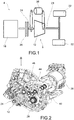
figure 1 is a schematic view of a power unit according to the present invention; -
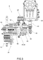
figure 2 is a perspective view of a transmission apparatus of a power unit according to an embodiment of the present invention; -
figure 3 is a view of the transmission apparatus offigure 2 , from the side of arrow III offigure 2 , in a configuration of disengagement; -
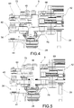
figure 4 is a top view of the transmission apparatus according to an embodiment of the present invention in one configuration of engagement upstream of the automated manual transmission; -
figure 5 is a top view of the transmission apparatus according to an embodiment of the present invention, in a configuration of engagement downstream of the automated manual transmission. - The elements or parts of elements in common between the embodiments described hereinafter will be indicated by the same numerical references.
- With reference to the aforementioned figures, collectively indicated at 4 is a schematic overall view of a power unit comprising a
transmission apparatus 8 for vehicles equipped with automated manual transmission 12 (AMT) and aninternal combustion engine 16. - For the purposes of the present invention, the type of internal combustion engine used in the power unit is not indicated, meaning any type of internal combustion engine, both in the Otto cycle and in the diesel cycle.
- The
internal combustion engine 16 has a drive shaft which may be mechanically connected to an input shaft of thetransmission apparatus 8 by means of aclutch 20, in a known manner. - The
transmission apparatus 8 comprises the automatedmanual transmission 12, equipped with aninput shaft 24 and anoutput shaft 28. - The
input shaft 24, as seen, is configured to be selectively connected to theinternal combustion engine 16, for example by means of saidclutch 20. - The
output shaft 28 is configured in a manner to be mechanically connected to at least onedrive wheel 32 of a vehicle. - The
transmission apparatus 8 further comprises an auxiliaryelectric machine 36 having anauxiliary shaft 40 and anauxiliary transmission 44 selectively connectable to theinput shaft 24 and/or to theoutput shaft 28 of the automatedmanual transmission 12. - Generally, the auxiliary
electric machine 36 is an electric machine that may operate both as a motor and a generator to provide torque as needed and to generate electric power, for example during the braking or release phase, as better described below. - The
auxiliary transmission 44 comprises asingle transmission selector 48 movable in three positions, wherein: - in a first upstream engagement position (
figure 4 ), a mechanical connection is made between theauxiliary shaft 40 of the auxiliaryelectric machine 36 and saidinput shaft 24 of thetransmission apparatus 8, - in a second disengagement position, the
auxiliary shaft 40 of the auxiliaryelectric machine 36 is mechanically disconnected from saidinput 24 andoutput 28 shafts, - in a third downstream engagement position (
figure 5 ), a mechanical connection is made between theauxiliary shaft 40 of the auxiliaryelectric machine 36 and saidoutput shaft 28. - According to one embodiment, said
single transmission selector 48 is movable along an actuating stroke between said first, second and third positions. - Preferably, said
single transmission selector 48 is movable along an axial actuatingstroke 52, wherein said first and third positions are located at respective end strokes of the axial actuatingstroke 52, and wherein said second position is intermediate or interposed between said end strokes. - For example, said
single transmission selector 48 comprises a slider 56, movable between said first, second and third positions, the slider 56 being equipped with a pair ofgears 60 suitable to engage and disengage with the corresponding first and secondmechanical elements input shaft 24 and theoutput shaft 28 respectively. - According to one embodiment, said
gears 60 comprise frontal-engagement gears suitable to mesh with the corresponding first and secondmechanical elements input shaft 24 and to theoutput shaft 28 respectively in the first and in the third engagement positions. - Preferably the front engagements allow the engagement in a direction of engagement parallel to said axial actuating
stroke 52. - The
auxiliary transmission 44 comprises at least a firstauxiliary shaft 72 and a secondauxiliary shaft 76, wherein the firstauxiliary shaft 72 is integral in rotation with the firstmechanical element 64 and the secondauxiliary shaft 76 is integral in rotation with the secondmechanical element 68. - Said
single transmission selector 48 comprises an actuator that moves it to said three positions; thetransmission apparatus 8 comprises a processing and control unit (not shown) which controls the actuator of thetransmission selector 48 and the automatedmanual transmission 12. - In this way, it is possible to synchronize the intervention of the auxiliary
electric machine 36 according to the operation of the automated manual transmission. - The operation of a transmission apparatus and a power unit according to the present invention will now be described.
- In particular, in a standard operating condition, i.e. in the second disengagement position, the
auxiliary shaft 40 of the auxiliaryelectric machine 36 is mechanically disconnected from theinput 24 and output 28 shafts. In this operating condition, both theinternal combustion engine 16 and the automatedmanual transmission 12 work without receiving any auxiliary power from the auxiliaryelectric machine 36 which is unable to provide torque, operating as a motor, nor to receive torque, operating as a generator. - If necessary, depending on the operating condition of the vehicle, it may pass into the first upstream engagement condition (
figure 4 ), wherein a mechanical connection is made between theauxiliary shaft 40 of the auxiliaryelectric machine 36 and theinput shaft 24. Such condition is obtained by actuating thetransmission selector 48 which, translating in theaxial actuating stroke 52, makes the mechanical connection between the auxiliaryelectric machine 36 and theinput shaft 24 by mechanical coupling between thegearing 60 and the firstmechanical element 64. In this way, it is possible to provide torque to the input of the automatedmanual transmission 12, for example, for a quick synchronization of a gear change, having previously disconnected theclutch 20, or to start the internal combustion engine (having beforehand placed the automated manual transmission in the neutral position), or to provide additional torque to theinternal combustion engine 16. - If necessary, depending on the operating condition of the vehicle, it may pass into the third upstream engagement condition (
figure 5 ), wherein a mechanical connection is made between theauxiliary shaft 40 of the auxiliaryelectric machine 36 and theoutput shaft 28. Such condition is obtained by actuating thetransmission selector 48 which, translating in theaxial actuating stroke 52, makes the mechanical connection between the auxiliaryelectric machine 36 and theoutput shaft 28 by mechanical coupling between thegearing 60 and the secondmechanical element 68. In this way, there is a possibility to provide torque at the output of the automatedmanual transmission 12, for example to cover a torque gap, or to achieve a regenerative braking or to provide additional torque to theinternal combustion engine 16. - As may be appreciated from the foregoing, the transmission apparatus for vehicles equipped with an automated manual transmission according to the invention allows the disadvantages presented in the prior art to be overcome.
- Advantageously, the transmission apparatus according to the present invention allows the auxiliary electric machine to be connected repeatedly and alternatively to the transmission in a quick, efficient and reliable manner.
- The transmission apparatus does not cause a significant increase in mass and bulk of the transmission, unlike known solutions.
- The present invention allows one to obtain all the functions necessary to optimize the transmission's operation, the fuel consumption and driving sensation of the vehicle with which it is provided, e.g.: transmission in exclusively electrical mode, startup of the internal combustion engine, torque gap filling during gear shifting, energy savings in the torque release phase (sailing), regenerative braking for recharging the battery pack, overboost both to increase performance in general and to compensate for the turbo lag of the possible overcharging of the internal combustion engine.
- All of these functions may be obtained through a suitable and continuous strategy for connecting and disconnecting the auxiliary unit from the transmission apparatus in a fast and reliable manner.
- Such a strategy includes the mechanical disconnection of the auxiliary unit from the transmission, when no intervention of the auxiliary unit is required in order to avoid dragging inertia as well as the mechanical connection of the auxiliary unit upstream or downstream of the transmission as a function of the driver's needs, of the battery pack charging status, and the conditions of the route followed by the vehicle.
- Connection and disconnection through the use of a single selector is particularly fast, precise and reliable. It also simplifies management and control of the transmission since each position of the single transmission selector, i.e. the disengagement, the upstream engagement of the transmission and the downstream engagement of the transmission, allows a single possible condition of operation, automatically excluding the others.
- In other words, when the transmission selector is in the upstream engagement position, it is automatically stopped from the downstream disengagement and engagement, and so on.
- There is not therefore the complication of having to coordinate and synchronize multiple actuator devices by means of a dedicated control unit in order to always ensure the correct operation of the transmission.
- In this way, there is not the risk that a malfunction in the system management and control may lead to a lag and a possible breakdown of the various actuators.
- It should also be considered that in the state of driving in city traffic, the operations of the actuator may also be on the order of dozens per minute and always need to ensure the reliability of the transmission management.
- Furthermore, the reduction in the number of actuators results in a reduction in overall bulk, weight and overall costs of the transmission apparatus.
- In addition, the reduction of the number of components also reduces the likelihood of malfunctions of the apparatus.
- The present invention is particularly suitable to be optimized by adapting automatically to the route to be followed with the vehicle, depending on the contingent position of the vehicle itself.
- Specifically, if the vehicle is following a predetermined route, for example, one set in a satellite navigator that the vehicle is equipped with, at any moment, and in advance, it is possible to know and predict the type of route the vehicle will have to follow, estimating the speed but also the demand for torque due, for example, to the possible gradient of the road segment. In this way, it is possible to control the transmission apparatus in advance, by choosing the proper operating logic of the auxiliary electric machine, but also the gear of the automated manual transmission to be engaged. Obviously, this type of transmission apparatus management is also possible without a predetermined route to be followed, since, due to the GPS, it is possible to know the instantaneous position of the vehicle and the gradient of the road section that is being traveled on or that one is presumably faced with and so on.
- This optimized management of the transmission apparatus allows a reduction of the vehicle's fuel consumption to be calibrated specifically as a function of the route taken, for example, to favor electric traction and recovery of kinetic energy during the release and/or braking phase.
- A person skilled in the art, in the object of satisfying contingent and specific requirements, may make numerous modifications and variations to the transmission apparatuses for vehicles equipped with automated manual transmission described above, all of which are within the scope of the invention as defined by the following claims.
Claims (8)
- Transmission apparatus (8) for vehicles equipped with an automated manual transmission (12), comprising- an automated manual transmission (12), provided with an input shaft (24) and an output shaft (28),- wherein the input shaft (24) is configured to be selectively connected to an internal combustion engine (16),- wherein the output shaft (28) is configured to be mechanically connected to at least one drive wheel (32) of a vehicle,- an auxiliary electric machine (36) having an auxiliary shaft (40) and an auxiliary transmission (44) selectively connectable to the input shaft (24) and/or to the output shaft (28) of the automated manual transmission (12),- wherein the auxiliary transmission (44) comprises a single transmission selector (48) movable in three positions, wherein said single transmission selector (48) :- in a first upstream engagement position, makes a mechanical connection between the auxiliary shaft (40) of the auxiliary electric machine (36) and said input shaft (24),- in a second disengagement position, mechanically disconnects the auxiliary shaft (40) of the auxiliary electric machine (36) from said input (24) and output (28) shafts,- in a third downstream engagement position, makes a mechanical connection between the auxiliary shaft (40) of the auxiliary electric machine (36) and said output shaft (28).
- Transmission apparatus (8) for vehicles equipped with an automated manual transmission (12) according to claim 1, wherein said single transmission selector (48) is movable along an actuating stroke including said first, second and third positions.
- Transmission apparatus (8) for vehicles equipped with an automated manual transmission (12) according to claim 1 or 2, wherein said single transmission selector (48) is movable along an axial actuating stroke (52), wherein said first and third positions are located in correspondence of respective end strokes of the axial actuating stroke (52), and wherein said second position is intermediate or interposed between said end strokes.
- Transmission apparatus (8) for vehicles equipped with an automated manual transmission (12) according to any of claims 1 to 3, wherein said single transmission selector (48) comprises a slider (56), movable between said first, second and third positions, the slider (56) being provided with a pair of gears (60) suitable to engage and disengage with corresponding first and second mechanical elements (64, 68) operatively connected, respectively, to the input shaft (24) and the output shaft (28).
- Transmission apparatus (8) for vehicles equipped with an automated manual transmission (12) according to claim 4, wherein said gears (60) comprise frontal-engagement gears suitable to mesh with the corresponding first and second mechanical elements (64, 68) operatively connected, respectively, to the input shaft (24) and to the output shaft (28) in the first and in the third engagement positions.
- Transmission apparatus (8) for vehicles equipped with an automated manual transmission (12) according to claim 4 or 5, wherein the auxiliary transmission (44) comprises at least a first auxiliary shaft (72) and a second auxiliary shaft (76), wherein the first auxiliary shaft (72) is integral in rotation with the first mechanical element (64) and the second auxiliary shaft (76) is integral in rotation with the second mechanical element (68).
- Transmission apparatus (8) for vehicles equipped with an automated manual transmission (12) according to any of the preceding claims, wherein said single transmission selector (48) comprises an actuator that moves it in said three positions, the transmission apparatus (8) comprising processing and control unit that commands the actuator of the transmission selector (48) and the automated manual transmission (12).
- Power unit (4) comprising a transmission apparatus (8) for vehicles equipped with an automated manual transmission (12) according to any of the preceding claims, and an internal combustion engine (16) having a drive shaft mechanically connectable to the input shaft (24) of the transmission apparatus (8) by means of a clutch (20).
Applications Claiming Priority (1)
| Application Number | Priority Date | Filing Date | Title |
|---|---|---|---|
| ITUA2016A004676A ITUA20164676A1 (en) | 2016-06-27 | 2016-06-27 | TRANSMISSION APPARATUS FOR VEHICLES EQUIPPED WITH ROBOTISED MANUAL TRANSMISSION, POWER UNIT AND RELATED VEHICLE RELATED TO THIS EQUIPMENT |
Publications (2)
| Publication Number | Publication Date |
|---|---|
| EP3263380A1 true EP3263380A1 (en) | 2018-01-03 |
| EP3263380B1 EP3263380B1 (en) | 2019-04-03 |
Family
ID=57209800
Family Applications (1)
| Application Number | Title | Priority Date | Filing Date |
|---|---|---|---|
| EP17176968.0A Not-in-force EP3263380B1 (en) | 2016-06-27 | 2017-06-20 | Transmission apparatus for an automated manual transmission, power unit and the related vehicle comprising said apparatus |
Country Status (4)
| Country | Link |
|---|---|
| EP (1) | EP3263380B1 (en) |
| JP (1) | JP2018058571A (en) |
| CN (1) | CN107539303A (en) |
| IT (1) | ITUA20164676A1 (en) |
Cited By (1)
| Publication number | Priority date | Publication date | Assignee | Title |
|---|---|---|---|---|
| FR3096311A1 (en) * | 2019-05-24 | 2020-11-27 | Renault S.A.S | AUTOMOTIVE VEHICLE HYBRID TRACTION DEVICE |
Families Citing this family (1)
| Publication number | Priority date | Publication date | Assignee | Title |
|---|---|---|---|---|
| US11745579B2 (en) * | 2021-04-05 | 2023-09-05 | Eaton Cummins Automated Transmission Technologies Llc | Full power-shift hybrid transmission and hybrid torquefill in automated manual transmission |
Citations (3)
| Publication number | Priority date | Publication date | Assignee | Title |
|---|---|---|---|---|
| US20020173401A1 (en) * | 2001-04-09 | 2002-11-21 | Bowen Thomas C. | Hybrid drive system for motor vehicle with powershift transmission |
| EP2682293A1 (en) * | 2012-07-03 | 2014-01-08 | FERRARI S.p.A. | Automatic manual transmission for a hybrid car provided with an internal combustion engine and with an electrical machine |
| WO2015052389A1 (en) * | 2013-10-10 | 2015-04-16 | Technoboost | Motor vehicle powertrain and method of operation |
Family Cites Families (4)
| Publication number | Priority date | Publication date | Assignee | Title |
|---|---|---|---|---|
| CN103061945B (en) * | 2004-04-16 | 2015-07-29 | Avl里斯脱有限公司 | The method of controller start-up phase |
| DE102007029610A1 (en) * | 2007-06-27 | 2009-01-08 | Bayerische Motoren Werke Aktiengesellschaft | Hybrid vehicle, in particular hybrid vehicle with front-wheel drive |
| JP5340790B2 (en) * | 2009-04-08 | 2013-11-13 | アイシン・エーアイ株式会社 | Vehicle power transmission control device |
| DE102010008754B4 (en) * | 2010-02-15 | 2025-02-06 | Dr. Ing. H.C. F. Porsche Aktiengesellschaft | drive system, in particular for a motor vehicle |
-
2016
- 2016-06-27 IT ITUA2016A004676A patent/ITUA20164676A1/en unknown
-
2017
- 2017-06-20 EP EP17176968.0A patent/EP3263380B1/en not_active Not-in-force
- 2017-06-21 JP JP2017121464A patent/JP2018058571A/en active Pending
- 2017-06-27 CN CN201710500095.7A patent/CN107539303A/en active Pending
Patent Citations (3)
| Publication number | Priority date | Publication date | Assignee | Title |
|---|---|---|---|---|
| US20020173401A1 (en) * | 2001-04-09 | 2002-11-21 | Bowen Thomas C. | Hybrid drive system for motor vehicle with powershift transmission |
| EP2682293A1 (en) * | 2012-07-03 | 2014-01-08 | FERRARI S.p.A. | Automatic manual transmission for a hybrid car provided with an internal combustion engine and with an electrical machine |
| WO2015052389A1 (en) * | 2013-10-10 | 2015-04-16 | Technoboost | Motor vehicle powertrain and method of operation |
Cited By (1)
| Publication number | Priority date | Publication date | Assignee | Title |
|---|---|---|---|---|
| FR3096311A1 (en) * | 2019-05-24 | 2020-11-27 | Renault S.A.S | AUTOMOTIVE VEHICLE HYBRID TRACTION DEVICE |
Also Published As
| Publication number | Publication date |
|---|---|
| CN107539303A (en) | 2018-01-05 |
| ITUA20164676A1 (en) | 2017-12-27 |
| JP2018058571A (en) | 2018-04-12 |
| EP3263380B1 (en) | 2019-04-03 |
Similar Documents
| Publication | Publication Date | Title |
|---|---|---|
| EP3535151B1 (en) | Transmission mounted electrical charging system with engine off coasting and dual mode hvac | |
| US10183569B2 (en) | Power generation control device for hybrid vehicle | |
| US10760682B2 (en) | Electrically driven vehicle start control device | |
| US9180878B2 (en) | Control device for hybrid vehicle | |
| CN106573529B (en) | Hybrid transmission with compensating electric machine and method for controlling gear changes | |
| US8880263B2 (en) | Control device for hybrid vehicle | |
| US10093166B2 (en) | Power generation control system for hybrid vehicle | |
| CA2722467A1 (en) | System and method for displaying power status of hybrid vehicle | |
| US20150274146A1 (en) | Clutch stroke adaptation on engine shutdown | |
| US20180186362A1 (en) | Hybrid vehicle transmission control device | |
| CN107683232A (en) | Energy management controls for hybrid vehicles | |
| EP3312478A1 (en) | Vehicle shift control device | |
| WO2017079423A1 (en) | Transmission system for commercial vehicle powertrain electrification | |
| US10525963B2 (en) | Control device in hybrid vehicle | |
| EP2862770B1 (en) | Method to control a hybrid vehicle during a gear shift phase | |
| EP3858693A1 (en) | Electric-powered vehicle control method and electric-powered vehicle drive system | |
| JP7298179B2 (en) | Electric vehicle control method and electric vehicle drive system | |
| CN105658464B (en) | Power system and method of operation for a motor vehicle | |
| EP3305616B1 (en) | Start control device for hybrid vehicle | |
| CN112537195A (en) | Hybrid electric vehicle power system and transmission method thereof | |
| JPWO2015034025A1 (en) | Hybrid vehicle drive device | |
| CN104417341A (en) | Hybrid power system for automobile, hybrid power automobile and control method of hybrid power automobile | |
| EP3263380B1 (en) | Transmission apparatus for an automated manual transmission, power unit and the related vehicle comprising said apparatus | |
| JP2017043206A (en) | Control device for hybrid vehicle | |
| CN104354583A (en) | Manual transmission integrated with driving motor |
Legal Events
| Date | Code | Title | Description |
|---|---|---|---|
| PUAI | Public reference made under article 153(3) epc to a published international application that has entered the european phase |
Free format text: ORIGINAL CODE: 0009012 |
|
| STAA | Information on the status of an ep patent application or granted ep patent |
Free format text: STATUS: THE APPLICATION HAS BEEN PUBLISHED |
|
| AK | Designated contracting states |
Kind code of ref document: A1 Designated state(s): AL AT BE BG CH CY CZ DE DK EE ES FI FR GB GR HR HU IE IS IT LI LT LU LV MC MK MT NL NO PL PT RO RS SE SI SK SM TR |
|
| AX | Request for extension of the european patent |
Extension state: BA ME |
|
| STAA | Information on the status of an ep patent application or granted ep patent |
Free format text: STATUS: REQUEST FOR EXAMINATION WAS MADE |
|
| 17P | Request for examination filed |
Effective date: 20180629 |
|
| RBV | Designated contracting states (corrected) |
Designated state(s): AL AT BE BG CH CY CZ DE DK EE ES FI FR GB GR HR HU IE IS IT LI LT LU LV MC MK MT NL NO PL PT RO RS SE SI SK SM TR |
|
| GRAP | Despatch of communication of intention to grant a patent |
Free format text: ORIGINAL CODE: EPIDOSNIGR1 |
|
| STAA | Information on the status of an ep patent application or granted ep patent |
Free format text: STATUS: GRANT OF PATENT IS INTENDED |
|
| INTG | Intention to grant announced |
Effective date: 20181031 |
|
| RIC1 | Information provided on ipc code assigned before grant |
Ipc: B60K 6/383 20071001AFI20171017BHEP |
|
| GRAS | Grant fee paid |
Free format text: ORIGINAL CODE: EPIDOSNIGR3 |
|
| GRAA | (expected) grant |
Free format text: ORIGINAL CODE: 0009210 |
|
| STAA | Information on the status of an ep patent application or granted ep patent |
Free format text: STATUS: THE PATENT HAS BEEN GRANTED |
|
| AK | Designated contracting states |
Kind code of ref document: B1 Designated state(s): AL AT BE BG CH CY CZ DE DK EE ES FI FR GB GR HR HU IE IS IT LI LT LU LV MC MK MT NL NO PL PT RO RS SE SI SK SM TR |
|
| REG | Reference to a national code |
Ref country code: GB Ref legal event code: FG4D |
|
| REG | Reference to a national code |
Ref country code: CH Ref legal event code: EP Ref country code: AT Ref legal event code: REF Ref document number: 1115284 Country of ref document: AT Kind code of ref document: T Effective date: 20190415 |
|
| REG | Reference to a national code |
Ref country code: DE Ref legal event code: R096 Ref document number: 602017003039 Country of ref document: DE |
|
| REG | Reference to a national code |
Ref country code: IE Ref legal event code: FG4D |
|
| REG | Reference to a national code |
Ref country code: NL Ref legal event code: MP Effective date: 20190403 |
|
| REG | Reference to a national code |
Ref country code: LT Ref legal event code: MG4D |
|
| REG | Reference to a national code |
Ref country code: AT Ref legal event code: MK05 Ref document number: 1115284 Country of ref document: AT Kind code of ref document: T Effective date: 20190403 |
|
| PG25 | Lapsed in a contracting state [announced via postgrant information from national office to epo] |
Ref country code: NL Free format text: LAPSE BECAUSE OF FAILURE TO SUBMIT A TRANSLATION OF THE DESCRIPTION OR TO PAY THE FEE WITHIN THE PRESCRIBED TIME-LIMIT Effective date: 20190403 |
|
| PG25 | Lapsed in a contracting state [announced via postgrant information from national office to epo] |
Ref country code: SE Free format text: LAPSE BECAUSE OF FAILURE TO SUBMIT A TRANSLATION OF THE DESCRIPTION OR TO PAY THE FEE WITHIN THE PRESCRIBED TIME-LIMIT Effective date: 20190403 Ref country code: LT Free format text: LAPSE BECAUSE OF FAILURE TO SUBMIT A TRANSLATION OF THE DESCRIPTION OR TO PAY THE FEE WITHIN THE PRESCRIBED TIME-LIMIT Effective date: 20190403 Ref country code: CZ Free format text: LAPSE BECAUSE OF FAILURE TO SUBMIT A TRANSLATION OF THE DESCRIPTION OR TO PAY THE FEE WITHIN THE PRESCRIBED TIME-LIMIT Effective date: 20190403 Ref country code: FI Free format text: LAPSE BECAUSE OF FAILURE TO SUBMIT A TRANSLATION OF THE DESCRIPTION OR TO PAY THE FEE WITHIN THE PRESCRIBED TIME-LIMIT Effective date: 20190403 Ref country code: NO Free format text: LAPSE BECAUSE OF FAILURE TO SUBMIT A TRANSLATION OF THE DESCRIPTION OR TO PAY THE FEE WITHIN THE PRESCRIBED TIME-LIMIT Effective date: 20190703 Ref country code: ES Free format text: LAPSE BECAUSE OF FAILURE TO SUBMIT A TRANSLATION OF THE DESCRIPTION OR TO PAY THE FEE WITHIN THE PRESCRIBED TIME-LIMIT Effective date: 20190403 Ref country code: AL Free format text: LAPSE BECAUSE OF FAILURE TO SUBMIT A TRANSLATION OF THE DESCRIPTION OR TO PAY THE FEE WITHIN THE PRESCRIBED TIME-LIMIT Effective date: 20190403 Ref country code: PT Free format text: LAPSE BECAUSE OF FAILURE TO SUBMIT A TRANSLATION OF THE DESCRIPTION OR TO PAY THE FEE WITHIN THE PRESCRIBED TIME-LIMIT Effective date: 20190803 Ref country code: HR Free format text: LAPSE BECAUSE OF FAILURE TO SUBMIT A TRANSLATION OF THE DESCRIPTION OR TO PAY THE FEE WITHIN THE PRESCRIBED TIME-LIMIT Effective date: 20190403 |
|
| PG25 | Lapsed in a contracting state [announced via postgrant information from national office to epo] |
Ref country code: BG Free format text: LAPSE BECAUSE OF FAILURE TO SUBMIT A TRANSLATION OF THE DESCRIPTION OR TO PAY THE FEE WITHIN THE PRESCRIBED TIME-LIMIT Effective date: 20190703 Ref country code: GR Free format text: LAPSE BECAUSE OF FAILURE TO SUBMIT A TRANSLATION OF THE DESCRIPTION OR TO PAY THE FEE WITHIN THE PRESCRIBED TIME-LIMIT Effective date: 20190704 Ref country code: PL Free format text: LAPSE BECAUSE OF FAILURE TO SUBMIT A TRANSLATION OF THE DESCRIPTION OR TO PAY THE FEE WITHIN THE PRESCRIBED TIME-LIMIT Effective date: 20190403 Ref country code: LV Free format text: LAPSE BECAUSE OF FAILURE TO SUBMIT A TRANSLATION OF THE DESCRIPTION OR TO PAY THE FEE WITHIN THE PRESCRIBED TIME-LIMIT Effective date: 20190403 Ref country code: RS Free format text: LAPSE BECAUSE OF FAILURE TO SUBMIT A TRANSLATION OF THE DESCRIPTION OR TO PAY THE FEE WITHIN THE PRESCRIBED TIME-LIMIT Effective date: 20190403 |
|
| PG25 | Lapsed in a contracting state [announced via postgrant information from national office to epo] |
Ref country code: AT Free format text: LAPSE BECAUSE OF FAILURE TO SUBMIT A TRANSLATION OF THE DESCRIPTION OR TO PAY THE FEE WITHIN THE PRESCRIBED TIME-LIMIT Effective date: 20190403 Ref country code: IS Free format text: LAPSE BECAUSE OF FAILURE TO SUBMIT A TRANSLATION OF THE DESCRIPTION OR TO PAY THE FEE WITHIN THE PRESCRIBED TIME-LIMIT Effective date: 20190803 |
|
| REG | Reference to a national code |
Ref country code: DE Ref legal event code: R097 Ref document number: 602017003039 Country of ref document: DE |
|
| PG25 | Lapsed in a contracting state [announced via postgrant information from national office to epo] |
Ref country code: EE Free format text: LAPSE BECAUSE OF FAILURE TO SUBMIT A TRANSLATION OF THE DESCRIPTION OR TO PAY THE FEE WITHIN THE PRESCRIBED TIME-LIMIT Effective date: 20190403 Ref country code: DK Free format text: LAPSE BECAUSE OF FAILURE TO SUBMIT A TRANSLATION OF THE DESCRIPTION OR TO PAY THE FEE WITHIN THE PRESCRIBED TIME-LIMIT Effective date: 20190403 Ref country code: RO Free format text: LAPSE BECAUSE OF FAILURE TO SUBMIT A TRANSLATION OF THE DESCRIPTION OR TO PAY THE FEE WITHIN THE PRESCRIBED TIME-LIMIT Effective date: 20190403 Ref country code: SK Free format text: LAPSE BECAUSE OF FAILURE TO SUBMIT A TRANSLATION OF THE DESCRIPTION OR TO PAY THE FEE WITHIN THE PRESCRIBED TIME-LIMIT Effective date: 20190403 Ref country code: MC Free format text: LAPSE BECAUSE OF FAILURE TO SUBMIT A TRANSLATION OF THE DESCRIPTION OR TO PAY THE FEE WITHIN THE PRESCRIBED TIME-LIMIT Effective date: 20190403 |
|
| PLBE | No opposition filed within time limit |
Free format text: ORIGINAL CODE: 0009261 |
|
| STAA | Information on the status of an ep patent application or granted ep patent |
Free format text: STATUS: NO OPPOSITION FILED WITHIN TIME LIMIT |
|
| PG25 | Lapsed in a contracting state [announced via postgrant information from national office to epo] |
Ref country code: SM Free format text: LAPSE BECAUSE OF FAILURE TO SUBMIT A TRANSLATION OF THE DESCRIPTION OR TO PAY THE FEE WITHIN THE PRESCRIBED TIME-LIMIT Effective date: 20190403 |
|
| 26N | No opposition filed |
Effective date: 20200106 |
|
| REG | Reference to a national code |
Ref country code: BE Ref legal event code: MM Effective date: 20190630 |
|
| PG25 | Lapsed in a contracting state [announced via postgrant information from national office to epo] |
Ref country code: TR Free format text: LAPSE BECAUSE OF FAILURE TO SUBMIT A TRANSLATION OF THE DESCRIPTION OR TO PAY THE FEE WITHIN THE PRESCRIBED TIME-LIMIT Effective date: 20190403 |
|
| PG25 | Lapsed in a contracting state [announced via postgrant information from national office to epo] |
Ref country code: IE Free format text: LAPSE BECAUSE OF NON-PAYMENT OF DUE FEES Effective date: 20190620 |
|
| PG25 | Lapsed in a contracting state [announced via postgrant information from national office to epo] |
Ref country code: LU Free format text: LAPSE BECAUSE OF NON-PAYMENT OF DUE FEES Effective date: 20190620 Ref country code: BE Free format text: LAPSE BECAUSE OF NON-PAYMENT OF DUE FEES Effective date: 20190630 Ref country code: SI Free format text: LAPSE BECAUSE OF FAILURE TO SUBMIT A TRANSLATION OF THE DESCRIPTION OR TO PAY THE FEE WITHIN THE PRESCRIBED TIME-LIMIT Effective date: 20190403 |
|
| REG | Reference to a national code |
Ref country code: CH Ref legal event code: PL |
|
| PG25 | Lapsed in a contracting state [announced via postgrant information from national office to epo] |
Ref country code: LI Free format text: LAPSE BECAUSE OF NON-PAYMENT OF DUE FEES Effective date: 20200630 Ref country code: CH Free format text: LAPSE BECAUSE OF NON-PAYMENT OF DUE FEES Effective date: 20200630 |
|
| PG25 | Lapsed in a contracting state [announced via postgrant information from national office to epo] |
Ref country code: CY Free format text: LAPSE BECAUSE OF FAILURE TO SUBMIT A TRANSLATION OF THE DESCRIPTION OR TO PAY THE FEE WITHIN THE PRESCRIBED TIME-LIMIT Effective date: 20190403 |
|
| PG25 | Lapsed in a contracting state [announced via postgrant information from national office to epo] |
Ref country code: MT Free format text: LAPSE BECAUSE OF FAILURE TO SUBMIT A TRANSLATION OF THE DESCRIPTION OR TO PAY THE FEE WITHIN THE PRESCRIBED TIME-LIMIT Effective date: 20190403 Ref country code: HU Free format text: LAPSE BECAUSE OF FAILURE TO SUBMIT A TRANSLATION OF THE DESCRIPTION OR TO PAY THE FEE WITHIN THE PRESCRIBED TIME-LIMIT; INVALID AB INITIO Effective date: 20170620 |
|
| GBPC | Gb: european patent ceased through non-payment of renewal fee |
Effective date: 20210620 |
|
| PG25 | Lapsed in a contracting state [announced via postgrant information from national office to epo] |
Ref country code: GB Free format text: LAPSE BECAUSE OF NON-PAYMENT OF DUE FEES Effective date: 20210620 |
|
| PG25 | Lapsed in a contracting state [announced via postgrant information from national office to epo] |
Ref country code: MK Free format text: LAPSE BECAUSE OF FAILURE TO SUBMIT A TRANSLATION OF THE DESCRIPTION OR TO PAY THE FEE WITHIN THE PRESCRIBED TIME-LIMIT Effective date: 20190403 |
|
| PGFP | Annual fee paid to national office [announced via postgrant information from national office to epo] |
Ref country code: IT Payment date: 20220518 Year of fee payment: 6 Ref country code: FR Payment date: 20220519 Year of fee payment: 6 Ref country code: DE Payment date: 20220518 Year of fee payment: 6 |
|
| REG | Reference to a national code |
Ref country code: DE Ref legal event code: R119 Ref document number: 602017003039 Country of ref document: DE |
|
| PG25 | Lapsed in a contracting state [announced via postgrant information from national office to epo] |
Ref country code: DE Free format text: LAPSE BECAUSE OF NON-PAYMENT OF DUE FEES Effective date: 20240103 |
|
| PG25 | Lapsed in a contracting state [announced via postgrant information from national office to epo] |
Ref country code: FR Free format text: LAPSE BECAUSE OF NON-PAYMENT OF DUE FEES Effective date: 20230630 |
|
| PG25 | Lapsed in a contracting state [announced via postgrant information from national office to epo] |
Ref country code: IT Free format text: LAPSE BECAUSE OF NON-PAYMENT OF DUE FEES Effective date: 20230620 |