EP3263364A1 - Tire tread and tire having tread - Google Patents
Tire tread and tire having tread Download PDFInfo
- Publication number
- EP3263364A1 EP3263364A1 EP16768530.4A EP16768530A EP3263364A1 EP 3263364 A1 EP3263364 A1 EP 3263364A1 EP 16768530 A EP16768530 A EP 16768530A EP 3263364 A1 EP3263364 A1 EP 3263364A1
- Authority
- EP
- European Patent Office
- Prior art keywords
- tire
- small recesses
- tread
- ground contact
- snow
- Prior art date
- Legal status (The legal status is an assumption and is not a legal conclusion. Google has not performed a legal analysis and makes no representation as to the accuracy of the status listed.)
- Granted
Links
Images

Classifications
-
- B—PERFORMING OPERATIONS; TRANSPORTING
- B60—VEHICLES IN GENERAL
- B60C—VEHICLE TYRES; TYRE INFLATION; TYRE CHANGING; CONNECTING VALVES TO INFLATABLE ELASTIC BODIES IN GENERAL; DEVICES OR ARRANGEMENTS RELATED TO TYRES
- B60C11/00—Tyre tread bands; Tread patterns; Anti-skid inserts
- B60C11/03—Tread patterns
- B60C11/032—Patterns comprising isolated recesses
-
- B—PERFORMING OPERATIONS; TRANSPORTING
- B60—VEHICLES IN GENERAL
- B60C—VEHICLE TYRES; TYRE INFLATION; TYRE CHANGING; CONNECTING VALVES TO INFLATABLE ELASTIC BODIES IN GENERAL; DEVICES OR ARRANGEMENTS RELATED TO TYRES
- B60C11/00—Tyre tread bands; Tread patterns; Anti-skid inserts
- B60C11/03—Tread patterns
- B60C11/12—Tread patterns characterised by the use of narrow slits or incisions, e.g. sipes
- B60C11/1236—Tread patterns characterised by the use of narrow slits or incisions, e.g. sipes with special arrangements in the tread pattern
-
- B—PERFORMING OPERATIONS; TRANSPORTING
- B60—VEHICLES IN GENERAL
- B60C—VEHICLE TYRES; TYRE INFLATION; TYRE CHANGING; CONNECTING VALVES TO INFLATABLE ELASTIC BODIES IN GENERAL; DEVICES OR ARRANGEMENTS RELATED TO TYRES
- B60C11/00—Tyre tread bands; Tread patterns; Anti-skid inserts
-
- B—PERFORMING OPERATIONS; TRANSPORTING
- B60—VEHICLES IN GENERAL
- B60C—VEHICLE TYRES; TYRE INFLATION; TYRE CHANGING; CONNECTING VALVES TO INFLATABLE ELASTIC BODIES IN GENERAL; DEVICES OR ARRANGEMENTS RELATED TO TYRES
- B60C11/00—Tyre tread bands; Tread patterns; Anti-skid inserts
- B60C11/03—Tread patterns
-
- B—PERFORMING OPERATIONS; TRANSPORTING
- B60—VEHICLES IN GENERAL
- B60C—VEHICLE TYRES; TYRE INFLATION; TYRE CHANGING; CONNECTING VALVES TO INFLATABLE ELASTIC BODIES IN GENERAL; DEVICES OR ARRANGEMENTS RELATED TO TYRES
- B60C11/00—Tyre tread bands; Tread patterns; Anti-skid inserts
- B60C11/03—Tread patterns
- B60C11/12—Tread patterns characterised by the use of narrow slits or incisions, e.g. sipes
-
- B—PERFORMING OPERATIONS; TRANSPORTING
- B60—VEHICLES IN GENERAL
- B60C—VEHICLE TYRES; TYRE INFLATION; TYRE CHANGING; CONNECTING VALVES TO INFLATABLE ELASTIC BODIES IN GENERAL; DEVICES OR ARRANGEMENTS RELATED TO TYRES
- B60C11/00—Tyre tread bands; Tread patterns; Anti-skid inserts
- B60C11/03—Tread patterns
- B60C11/12—Tread patterns characterised by the use of narrow slits or incisions, e.g. sipes
- B60C11/1204—Tread patterns characterised by the use of narrow slits or incisions, e.g. sipes with special shape of the sipe
- B60C2011/1231—Tread patterns characterised by the use of narrow slits or incisions, e.g. sipes with special shape of the sipe being shallow, i.e. sipe depth of less than 3 mm
-
- B—PERFORMING OPERATIONS; TRANSPORTING
- B60—VEHICLES IN GENERAL
- B60C—VEHICLE TYRES; TYRE INFLATION; TYRE CHANGING; CONNECTING VALVES TO INFLATABLE ELASTIC BODIES IN GENERAL; DEVICES OR ARRANGEMENTS RELATED TO TYRES
- B60C11/00—Tyre tread bands; Tread patterns; Anti-skid inserts
- B60C11/03—Tread patterns
- B60C11/12—Tread patterns characterised by the use of narrow slits or incisions, e.g. sipes
- B60C11/1236—Tread patterns characterised by the use of narrow slits or incisions, e.g. sipes with special arrangements in the tread pattern
- B60C2011/1254—Tread patterns characterised by the use of narrow slits or incisions, e.g. sipes with special arrangements in the tread pattern with closed sipe, i.e. not extending to a groove
-
- B—PERFORMING OPERATIONS; TRANSPORTING
- B60—VEHICLES IN GENERAL
- B60C—VEHICLE TYRES; TYRE INFLATION; TYRE CHANGING; CONNECTING VALVES TO INFLATABLE ELASTIC BODIES IN GENERAL; DEVICES OR ARRANGEMENTS RELATED TO TYRES
- B60C11/00—Tyre tread bands; Tread patterns; Anti-skid inserts
- B60C11/03—Tread patterns
- B60C11/12—Tread patterns characterised by the use of narrow slits or incisions, e.g. sipes
- B60C2011/129—Sipe density, i.e. the distance between the sipes within the pattern
Definitions
- the present invention relates to a tire tread and to a tire having said tread, and more specifically the present invention relates to a tire tread and a tire having said tread, enabling an improvement in performance on snow when the tread is brand new, while maintaining wet performance.
- Winter tires which are also called “studless” tires are well known as tires which can travel on winter road surfaces covered with snow or ice. Winter tires are generally provided with a plurality of narrow incisions known as sipes which open at the ground contact surface, and adhesion to a road surface in winter is improved by means of what is known as an "edge” effect and a water film-removal effect, and also by using a compound which is softer than that used for tires which are not for winter use.
- Patent Document 1 A tire in which braking and drive performance is improved by forming narrow grooves on a tread surface of a ground contact element which makes contact with the road surface has been proposed as a means for improving gripping performance on a low-friction-coefficient road surface such as a winter road surface, and especially the gripping performance when the tread is brand new (initial period of wear) (Patent Document 1).
- Patent Document 3 Furthermore, there has also been a proposal for a tire in which a plurality of widthwise grooves extending along a tread width direction are formed, both ends of these widthwise grooves terminating within a block, and performance on snow is improved by an increase in snow column shear force (Patent Document 3).
- Patent Document 4 there has been a proposal for a tire in which recesses indented from a tire surface toward a tire inward direction are formed in a partial region of the tire surface.
- the recesses provided on the tire surface are formed in such a way as to improve rolling resistance performance, and furthermore the size thereof is excessively small, so it is difficult to improve the performance on ice and snow by means of these recesses.
- the present invention has been devised in order to solve the abovementioned problems in the prior art, and the aim thereof lies in providing a tire tread and a tire having said tread, which make it possible to demonstrate a higher level of performance on ice and snow when the tread is brand new, and in particular performance on snow, while maintaining wet performance.
- groove means a space having a width, depth and length, formed by two opposing surfaces (wall surfaces) which do not come into contact under normal usage conditions, and by another surface (bottom surface) connecting lower end portions of said opposing surfaces.
- the term "incision”, also referred to as a “sipe”, means a narrow incision formed from a tread surface inwardly in the radial direction by a thin blade having a shape like that of a knife blade, for example.
- the width of this "incision” at the tire surface is less than that of a transverse groove and is 2.0 mm or less, for example.
- the "incision” differs from a “groove” and when the tread surface constitutes a ground contact surface in contact with the road surface, it may be partially closed off.
- small recess means an element on the ground contact surface of the tread having a maximum length of 5.0 mm or less, in a portion which opens in the ground contact surface and is indented inwardly in the tire radial direction. This "small recess” is also relatively small, with a maximum depth in the tire radial direction of 3.0 mm or less, for example.
- projected length of a small recess means a length (mm) when a small recess present on an upper surface of a ground contact element is projected onto a plane parallel to a tire axis of rotation and perpendicular to the upper surface of the ground contact element.
- the term "projected density of small recesses” is a value obtained by dividing the total projected length (mm) of the small recesses present on the upper surface of a ground contact element, projected on a plane parallel to the tire axis of rotation and perpendicular to the upper surface of the ground contact element, by the surface area (mm 2 ) of the upper surface of the ground contact element when the small recesses are not present, and multiplying the result by 1000, in other words: ⁇ projected length of small recesses / surface area of upper surface of ground contact element ⁇ 1000.
- small recesses are regularly arranged means that the small recesses are arranged on the upper surface of the ground contact element in a regular arrangement such as in a staggered form, lattice form, linear form or tile form, for example.
- the present invention provides a tire tread comprising: a plurality of ground contact elements which are defined by a plurality of grooves formed on a ground contact surface in contact with a road surface when a tire is rolling, and having an upper surface forming a portion of the ground contact surface; and a plurality of small recesses which open at the upper surface, are indented inwardly in the tire radial direction, and are not in communication with each other, said tire tread being characterized in that the depth h of the small recesses is between 0.15 mm and 1.5 mm when the tread is brand new, and the projected density of the small recesses (a value obtained by dividing the total projected length LP (mm) of the small recesses present on the upper surface, projected on a plane parallel to the tire axis of rotation and perpendicular to the upper surface, by the surface area (mm 2 ) of the upper surface when the small recesses are not present, and multiplying the result by 1000) is 200 or greater.
- the depth h of the small recesses is
- the projected density of the small recesses on the upper surface of the ground contact elements is 200 or greater, and it is possible as a result to enhance what is known as the "edge effect" acting on an icy and snowy road surface, and in particular a snowy road surface, and the performance on ice and snow when the tread is brand new is improved, especially the performance on snow.
- the projected density of the small recesses on the upper surface of the ground contact elements is preferably 250 or greater, more preferably 300 or greater, and even more preferably between 350 and 600.
- the depth h of the small recesses is set at between 0.15 mm and 1.5 mm when the tread is brand new, it is possible to cause the small recesses to act as a space for taking in grains of snow, and it is possible to improve the performance on snow when the tread is brand new while maintaining the wet performance.
- the depth h of the small recesses is less than 0.15 mm when the tread is brand new, grains of snow are not readily taken in by the small recesses and there is a risk of it not being possible to adequately improve the performance on snow.
- the depth h of the small recesses is greater than 1.5 mm when the tire is brand new, there is a reduction in rigidity in the surface region of the ground contact surface and minute inward collapse in the surface region of the ground contact surface is not readily restricted, so there is a risk of a deterioration in the wet performance. The abovementioned range is therefore preferred.
- the depth h of the small recesses is preferably between 0.2 mm and 1.5 mm when the tread is brand new, and more preferably between 0.3 mm and 1.0 mm.
- the small recesses are preferably not in communication with the grooves provided in the ground contact surface.
- a mode having the configuration described above makes it possible to more reliably restrict a localized reduction in rigidity in the surface region of the ground contact surface by virtue of the fact that the small recesses are not in communication with the grooves, and as a result it is possible to maintain the wet performance more reliably while envisaging an improvement in performance on snow afforded by the small recesses when the tread is brand new.
- the small recesses are preferably not in communication with narrow incisions either, when such narrow incisions are provided in the ground contact elements.
- the small recesses are preferably regularly arranged on the upper surface of the ground contact elements.
- a mode having the configuration described above makes it possible to restrict concentration of stress in a portion of the upper surface of the ground contact elements, and as a result it is possible to more reliably restrict minute inward collapse in the surface region of the ground contact surface. Furthermore, grains of snow can be taken in by the small recesses more efficiently so it is possible to maintain the wet performance while envisaging an improvement in the performance on snow afforded by the small recesses when the tread is brand new.
- the small recesses comprise a transverse sectional shape having a short direction length LS and a long direction length LL , the projected length LP projected on a plane parallel to the tire axis of rotation and perpendicular to the upper surface of the ground contact elements being greater than the short direction length LS .
- the small recesses have a shape that undergoes greater deformation but is elongate in a favorable manner, so it is possible to more reliably restrict a reduction in rigidity in the surface region of the ground contact surface and as a result it is possible to more reliably restrict minute inward collapse in the surface region of the ground contact surface.
- the small recesses are arranged in such a way that the long direction thereof forms a relatively small angle with respect to the tire circumferential direction, and as a result it is possible to more reliably achieve what is known as the edge effect afforded by the edges of the small recesses that act on icy and snowy road surfaces, and especially snowy road surfaces; it is therefore possible to maintain the wet performance while envisaging an improvement in the performance on snow afforded by the small recesses when the tread is brand new.
- the long direction length LL of the small recesses is between 0.15 mm and 3.0 mm.
- a mode having the configuration described above makes it possible to maintain the wet performance while reliably improving the performance on snow afforded by the small recesses when the tread is brand new. That is to say, if the long direction length LL of the small recesses is less than 0.15 mm, grains of snow are not readily taken in by the small recesses and there is a risk of it being difficult to improve the performance on snow.
- the long direction length LL of the small recesses is greater than 3.0 mm, not only does it become difficult to increase the density of the small recesses, it is also difficult to restrict a reduction in the rigidity in the surface region of the ground contact surface caused by the small recesses so there is a risk of it being difficult to maintain the wet performance while improving the performance on snow.
- the long direction length LL of the small recesses is more preferably between 0.5 mm and 2.5 mm, and even more preferably between 1.0 mm and 2.0 mm.
- the short direction length LS of the small recesses is preferably between 0.15 mm and 0.5 mm.
- a mode having the configuration described above makes it possible to maintain the wet performance while reliably improving the performance on snow afforded by the small recesses when the tread is brand new. That is to say, if the short direction length LS of the small recesses is less than 0.15 mm, grains of snow are not readily taken in by the small recesses and there is a risk of it being difficult to improve the performance on snow.
- the short direction length LS of the small recesses is greater than 0.5 mm, not only does it become difficult to increase the density of the small recesses, it is also difficult to restrict a reduction in the rigidity in the surface region of the ground contact surface caused by the small recesses so there is a risk of it being difficult to maintain the wet performance while improving the performance on snow.
- the short direction length LS of the small recesses is more preferably between 0.2 mm and 0.4 mm, and even more preferably between 0.25 mm and 0.3 mm.
- an angle A (absolute value) between the long direction of the small recesses and the tire axial direction is preferably 45° or less.
- a mode having the configuration described above makes it possible to maintain the wet performance while reliably improving the performance on snow afforded by the small recesses when the red is brand new. That is to say, if the angle A (absolute value) between the long direction of the small recesses and the tire axial direction is greater than 45°, there is a risk of it being difficult to improve the performance on snow afforded by the recesses because the edge effect afforded by the small recesses decreases in relation to the tire circumferential direction.
- the angle A (absolute value) between the long direction of the small recesses and the tire axial direction is more preferably 30° or less, and even more preferably between 0° and 20°.
- the ground contact elements further comprise a narrow incision which opens at the upper surface of the ground contact elements and extends inwardly in the tire radial direction.
- the ground contact elements are provided with a narrow incision which opens at the upper surface of the ground contact elements and extends inwardly in the tire radial direction, which facilitates adjustment of the rigidity of the ground contact elements as a whole, and as a result the small recesses can be made to act more effectively.
- the narrow incision act as a space for temporarily storing water on a wet road surface
- the present invention having the configuration described above provides a tire tread and a tire comprising said tread which make it possible to demonstrate higher-level performance on snow when the tread is brand new, while restricting a deterioration in wet performance and employing small recesses.
- a tire tread according to a first mode of embodiment of the present invention will be described first of all with reference to fig. 1 to 3 . It should be noted that a tire having a size of 205/55R16 is an example of the tire to which a tread 1 according to this mode of embodiment is applied.
- Fig. 1 is an oblique view schematically illustrating a portion of the tire tread according to the first mode of embodiment of the present invention
- fig. 2 is an enlarged plan view of a portion illustrated by II in fig. 1
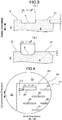
- fig. 3 is an enlargement in cross section along the line III-III in fig. 2 .
- the direction of the arrows marked as "Circumferential Orientation” denotes the tire circumferential direction (direction of rotation)
- the direction of the arrows marked as "Axial Orientation” denotes the tire axial direction
- the direction of the arrows marked as "Radial Orientation” denotes the tire radial direction.
- the tread 1 comprises a ground contact surface 2 which makes contact with the road surface when the tire is rolling.
- the ground contact surface 2 is formed with a plurality of grooves 3 which open at the ground contact surface 2 and extend in the tire circumferential direction and the tire axial direction, a plurality of ground contact elements 4 being defined by these grooves 3.
- the ground contact elements 4 comprise an upper surface 41 disposed on an outermost portion in the tire radial direction and forming a portion of the ground contact surface 2, and one narrow incision 6 which opens at the upper surface 41 and extends inwardly in the tire radial direction.
- the narrow incision 6 extends in the tire axial direction but is not in communication with the grooves 3.
- Small recesses 5 provided in the upper surface 41 of the ground contact elements 4 will be described next. As illustrated in fig. 2 , a plurality of the small recesses 5 which open at the upper surface 41 of the ground contact elements 4 and are indented inwardly in the tire radial direction are regularly arranged over the whole of the upper surface 41 of the ground contact elements 4.
- the small recesses 5 are formed in such a way as not to be in communication with each other and not to be in communication with the grooves 3 either, and furthermore not to be in communication with the narrow incision 6, although this is not depicted.
- the small recesses 5 have an elongate shape when seen in a plan view (i.e., a transverse sectional shape) on the upper surface 41 of the ground contact elements 4, this shape being an elongate rectangle according to this mode of embodiment.
- the long direction length LL in the transverse section of the small recesses 5 is preferably between 0.15 mm and 3.0 mm, more preferably between 0.5 mm and 2.5 mm, and even more preferably between 1.0 mm and 2.0 mm.
- the short direction length LS in the transverse section of the small recesses 5 is preferably between 0.15 mm and 0.5 mm, more preferably between 0.2 mm and 0.4 mm, and even more preferably between 0.25 mm and 0.3 mm.
- the small recesses according to this mode of embodiment have a long direction length LL of 2.0 mm and a short direction length LS of 0.5 mm, and substantially the same cross-sectional shape from the opening to a bottom portion.
- the small recesses 5 have a length extending from the upper surface 41 of the ground contact elements 4 in the tire radial direction, in other words a depth h .
- This depth h is preferably between 0.2 mm and 1.5 mm, and more preferably between 0.3 mm and 1.0 mm. According to this mode of embodiment, the depth h is 0.5 mm.
- the small recesses 5 are arranged in such a way that the long direction extends in the tire axial direction and the short direction extends in the tire circumferential direction. That is to say, according to this mode of embodiment, the short direction length LS of the small recesses 5 forms the tire circumferential length and the long direction length LL forms the tire axial length.
- the small recesses 5 are arranged in such a way that the long direction axis thereof forms an angle A (not depicted) of 0° with the tire axial direction, i.e. in such a way that the long direction axis extends in the tire axial direction.
- the angle A (absolute value) between the long direction axis of the small recesses 5 and the tire axial direction is preferably 45° or less, more preferably 30° or less, and even more preferably between 0° and 20°.
- the long direction length LL is equal to the projected length LP of the small recesses 5, projected on a plane parallel to the tire axis of rotation of the small recesses 5 and perpendicular to the upper surface 41 of the ground contact elements 4.
- the projected length LP is therefore greater than the short direction length LS of the small recesses 5.
- the plurality of small recesses 5 are regularly arranged in tile form on the upper surface 41 of the ground contact elements 4. That is to say, as illustrated in fig. 2 , rows in which the plurality of small recesses 5 are arranged linearly in the axial direction at intervals substantially equal to the long direction length LL are provided, and a plurality of rows are arranged in the circumferential direction. Each row is arranged in such a way that the small recesses 5 included in that row are arranged with an offset in such a way as to be aligned in the circumferential direction with a portion between the adjacent small recesses 5 within an adjacent row.
- the small recesses 5 are preferably provided in such a way that the projected density thereof (a value obtained by dividing the total projected length LP (mm) of the small recesses 5 present on the upper surface 41 of the ground contact elements 4, projected on a plane parallel to the tire axis of rotation and perpendicular to the upper surface 41 of the ground contact elements 4, by the surface area (mm 2 ) of the upper surface 41 of the ground contact elements 4 when the small recesses 5 are not present, and multiplying the result by 1000) is 200 or greater.
- the projected density is preferably 250 or greater, more preferably 300 or greater, and even more preferably between 350 and 600.
- the projected density of the small recesses 5 according to this mode of embodiment is 447.
- the small recesses 5 preferably have a shape in which the long direction length LL is constant across the tire radial direction, as illustrated in fig. 3(A) , but they may equally have a shape such that the long direction length LL gradually decreases at inward ends in the tire radial direction, as illustrated in fig. 3(B) , with the aim of improving processability and ensuring greater rigidity in the surface region.
- the plurality of small recesses 5 are not in communication with each other so it is possible to restrict a reduction in rigidity in the surface region of the ground contact surface and to restrict minute inward collapse in the surface region of the ground contact surface. It is possible to maintain the wet performance as a result. This effect is more reliable when the small recesses 5 are configured in such a way as not to communicate with the grooves 3 and the narrow incision 6.
- the depth h of the small recesses 5 provided in the upper surface 41 of the ground contact elements 4 is set at between 0.15 mm and 1.5 mm when the tread is brand new, it is possible to cause the small recesses 5 to act as a space for taking in the grains of snow while reliably restricting a reduction in rigidity in the surface region of the ground contact surface caused by the small recesses 5, and therefore it is possible to improve the performance on snow when the tread 1 is brand new while maintaining the wet performance as a result.
- the small recesses 5 have a shape that undergoes greater deformation but is elongate in a favorable manner because they include the short direction length LS and the long direction length LL , and by adopting a configuration such that the projected length LP of the small recesses 5 projected on a plane parallel to the tire axis of rotation and perpendicular to the upper surface 41 of the ground contact elements 4 is greater than the short direction length LS of the small recesses 5, it is possible to more reliably restrict a reduction in rigidity in the surface region of the ground contact surface and as a result it is possible to more reliably restrict minute inward collapse in the surface region of the ground contact surface.
- the long direction of the small recesses 5 in such a way as to act reliably in the tire circumferential direction, it is possible to more reliably achieve what is known as the edge effect by means of the small recesses 5 acting on an icy and snowy road surface, and especially a snowy road surface, so it is possible to maintain the wet performance while envisaging an improvement in the performance on snow afforded by the small recesses 5 when the tread 1 is brand new.
- the long direction length LL of the small recesses 5 By setting the long direction length LL of the small recesses 5 at between 0.15 mm and 3.0 mm, or setting the long direction length LL of the small recesses 5 at between 0.5 mm and 2.5 mm, it is possible to facilitate an improvement in the projected density of the small recesses 5 while maintaining a space enabling grains of snow to be taken in more reliably by the small recesses 5, and as a result it is possible to more reliably maintain the wet performance while envisaging an improvement in the performance on snow afforded by the small recesses 5 when the tread 1 is brand new.
- the long direction length LL of the small recesses 5 is less than 0.15 mm, grains of snow are not readily taken in by the small recesses 5 and there is a risk of it being difficult to improve the performance on snow.
- the long direction length LL of the small recesses 5 is greater than 3.0 mm, not only does it become difficult to increase the density of the small recesses 5, it is also difficult to restrict a reduction in the rigidity in the surface region of the ground contact surface caused by the small recesses 5 so there is a risk of it being difficult to maintain the wet performance while improving the performance on snow.
- the short direction length LS of the small recesses 5 is less than 0.15 mm, grains of snow are not readily taken in by the small recesses 5 and there is a risk of it being difficult to improve the performance on snow.
- the short direction length LS of the small recesses 5 is greater than 0.5 mm, not only does it become difficult to increase the density of the small recesses 5, it is also difficult to restrict a reduction in the rigidity in the surface region of the ground contact surface caused by the small recesses 5 so there is a risk of it being difficult to maintain the wet performance while improving the performance on snow.
- the small recesses 5 arranged regularly over the whole of the upper surface 41 of the ground contact elements 4 make it possible to restrict concentration of stress in a portion of the upper surface 41 of the ground contact elements 4, and as a result it is possible to more reliably restrict minute inward collapse in the surface region of the ground contact surface. Furthermore, grains of snow can be taken in by the small recesses 5 more efficiently so it is possible to maintain the wet performance while envisaging an improvement in the performance on snow afforded by the small recesses 5 when the tread 1 is brand new.
- the narrow incision 6 which opens at the upper surface 41 of the ground contact elements 4 and is provided on the ground contact elements 4 in such a way as to extend inwardly in the tire radial direction facilitates adjustment of the rigidity of the ground contact elements 4 as a whole, and as a result the small recesses 5 can be made to act more effectively. Furthermore, not only can the narrow incision 6 act as a space for temporarily storing water on a wet road surface, it is also possible on a snowy road surface for the edge effect afforded by the narrow incision 6 to act on said snowy road surface, and therefore it is possible to maintain the wet performance while improving the performance on snow to a greater degree when the tread 1 is brand new.
- the shape (transverse sectional shape) of the small recesses 5 when seen in a plan view is rectangular in the mode of embodiment described above, but a bale shape, a diamond shape or an elliptical shape, etc., is equally feasible.
- the plurality of small recesses 5 preferably have the same dimensions and shape within the same ground contact element 4, but they may equally be varied with the aim of improving various aspects of tire performance.
- the narrow incision 6 is provided in the mode of embodiment described above, but it is equally possible not to provide the narrow incision 6.
- the narrow incision 6 may equally have a shape in which one or both ends at the grooves 3 are open, a serrated shape when seen in a plan view of the upper surface 41 of the ground contact elements 4, or a shape combining serrations and straight lines.
- the narrow incision may equally have what is known as a three-dimensional shape with serrations in the tire radial direction.
- FIG. 4 is an enlarged plan view of a portion of a tire tread according to the second mode of embodiment of the present invention, corresponding to the portion illustrated by II in fig. 1 .
- the direction of the arrows in fig. 4 marked as "Circumferential Orientation” also denotes the tire circumferential direction (direction of rotation)
- the direction of the arrows marked as "Axial Orientation” also denotes the tire axial direction.
- the description of the second mode of embodiment will mainly relate only to those parts which are different from the tread of the abovementioned first mode of embodiment, and constituent elements which are the same will not be described again.
- a tread 21 according to the second mode of embodiment has a configuration in which a plurality of small recesses 25 which open at an upper surface 241 of ground contact elements 24, are indented inwardly in the tire radial direction and are not in communication with each other are formed on the upper surface 241 of the ground contact elements 24.
- the small recesses 25 have a shape when seen in a plan view of the upper surface 241 of the ground contact elements 24 (transverse sectional shape) which is substantially rectangular with both ends being arc-shaped (elongate bale-shaped).
- the long direction length LL of the small recesses 25 is 2.0 mm and the short direction length LS is 0.25 mm.
- the depth h of the small recesses 25 is 0.5 mm.
- the small recesses 25 are oriented in such a way that the long direction thereof is parallel to the tire axial direction and the short direction is parallel to the tire circumferential direction, and they are arranged regularly in a staggered form on the upper surface 241 of the ground contact elements 24. As a result, the angle A (not depicted) between the long direction of the small recesses 25 and the tire axial direction is 0°.
- the short direction length LS thus forms the tire circumferential direction length and the long direction length LL forms the tire axial direction length, so the projected length LP of the small recesses 25 projected on a plane parallel to the tire axis of rotation and perpendicular to the upper surface 241 of the ground contact elements 24 is greater than the short direction length LS of the small recesses 25.
- the small recesses 25 are provided in such a way that the projected density thereof is 200 or greater.
- the projected density of the small recesses 25 is 528 in the tread 21 according to this second mode of embodiment.
- the small recesses 25 are formed in such a way as not to be in communication with grooves 23, in the same way as with the small recesses 5 in the first mode of embodiment, and also in such a way as not to be in communication with a narrow incision, although this is not depicted.
- the tread 21 according to the second mode of embodiment comprises the small recesses 25 which are regularly arranged in a staggered form, and as a result it is possible to improve the projected density of the small recesses 25 on the upper surface 241 of the ground contact elements 24 while restricting concentration of stress in a portion of the upper surface 241 of the ground contact elements 24, and by enhancing what is known as the edge effect acting on an icy and snowy road surface, and especially a snowy road surface, it is possible to improve the performance on ice and snow when the tread 21 is brand new, and in particular the performance on snow.
- the short direction length LS of the small recesses 25 is shorter within a predetermined range, and the small recesses 25 have an elongate transverse sectional shape, whereby it is possible to more reliably restrict minute inward collapse at the surface region of the ground contact surface so it is possible to more reliably maintain the wet performance while envisaging an improvement in performance on snow afforded by the small recesses 25 when the tread 21 is brand new.
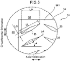
- FIG. 5 is an enlarged plan view of a portion of a tire tread according to a third mode of embodiment of the present invention, corresponding to the portion illustrated by II in fig. 1 .
- the direction of the arrows in fig. 5 marked as "Circumferential Orientation” also denotes the tire circumferential direction (direction of rotation)
- the direction of the arrows marked as "Axial Orientation” also denotes the tire axial direction.
- the description of the third mode of embodiment will mainly relate only to those parts which are different from the treads of the abovementioned first mode of embodiment and second mode of embodiment, and constituent elements which are the same will not be described again.
- a tread 31 according to the third mode of embodiment has a configuration in which a plurality of small recesses 35 which open at an upper surface 341 of ground contact elements 34, are indented inwardly in the tire radial direction and are not in communication with each other are formed on the upper surface 341 of the ground contact elements 34.
- the small recesses 35 have an elongate diamond shape when seen in a plan view (a transverse sectional shape) of the upper surface 41 of the ground contact elements 34.
- the long direction length LL is 2.0 mm and the short direction length LS is 0.5 mm.
- the depth h of the small recesses 35 is 0.75 mm.
- the small recesses 35 are oriented in the tire axial direction on the upper surface 341 of the ground contact elements 34 in such a way that the long direction of the small recesses 35 is inclined with respect to the tire axial direction, and they are regularly arranged in alignment in the tire circumferential direction and the tire axial direction.
- the angle A absolute value between the long direction axis (LA) of the small recesses 35 and the tire axial direction is 30°.
- the projected length LP of the small recesses 35 projected on a plane parallel to the tire axis of rotation and perpendicular to the upper surface 341 of the ground contact elements 34 is greater than the short direction length LS of the small recesses 35.
- the small recesses 35 provided on the upper surface 341 of the ground contact elements 34 are provided in such a way as to have a projected density of 200 or greater. According to the third mode of embodiment, the projected density of the small recesses 35 is 484.
- the small recesses 35 are formed in such a way as not to be in communication with the grooves 33, and also so as not to be in communication with a narrow incision, although this is not depicted.
- the tread 31 according to the third mode of embodiment comprises the small recesses 35 which are regularly arranged in alignment in the tire circumferential direction and the tire axial direction, and as a result it is possible to improve the projected density of the small recesses 35 on the upper surface 341 of the ground contact elements 34 while restricting concentration of stress in a portion of the upper surface 341 of the ground contact elements 34, and by enhancing what is known as the edge effect acting on an icy and snowy road surface, and especially a snowy road surface, it is possible to improve the performance on ice and snow when the tread 31 is brand new, and in particular the performance on snow.
- the angle A (absolute value) between the long direction axis (LA) of the small recesses 35 and the tire axial direction is set at 45° or less, and as a result it is possible to cause the edge effect afforded by the small recesses 35 to act in the tire axial direction while also reliably acting in the tire circumferential direction, and as a result it is possible to more reliably maintain the wet performance while envisaging an improvement in the performance on snow afforded by the small recesses 35 when the tread 31 is brand new.
- Test results employing a tire comprising the tire tread according to exemplary embodiments of the present invention will be described next.
- a test on snow was carried out using a tire having a tire tread according to exemplary embodiments 1-9, in which the density, depth, long direction length and short direction length of the small recesses were varied, and using a tire having a tire tread without small recesses (conventional example) as a comparative example.
- the tire size of the tires used for the test according to exemplary embodiments 1-9 and the conventional example was 205/55R16 in all cases, the tires being mounted on a 6.5J ⁇ 16 wheel with an internal pressure set at 200 kPa.
- Unused test tires were mounted on four wheels of a front-wheel-drive vehicle having a displacement of 2000 cc, using the abovementioned rim and internal pressure, and the vehicle traveled with one driver on a road surface of compacted snow, sudden braking was performed from a speed of 60 km/h to actuate the anti-lock braking system (ABS), and the deceleration was measured.
- the measured results are shown in table 1.
- the measured values are represented by an index with the conventional example being 100, and a higher numerical value is more favorable.
- a wet test was then carried out using tires having the tire tread according to abovementioned exemplary embodiments 1-4 and a tire having a tire tread without small recesses (conventional example) as a comparative example.
- the tire size of the tires used for the test according to exemplary embodiments 1-4 and the conventional example was 205/55R16 in all cases, the tires being mounted on a 6.5J ⁇ 16 wheel with an internal pressure set at 200 kPa.
- Unused test tires were mounted on four wheels of a front-wheel-drive vehicle having a displacement of 2000 cc, using the abovementioned rim and internal pressure, and the vehicle traveled with one driver on a wet road surface with a water depth of 2 mm, sudden braking was performed from a speed of 60 km/h to actuate the anti-lock braking system (ABS), and the braking distance until stoppage was measured.
- ABS anti-lock braking system
- Table 2 the measured values are represented by an index with the conventional example being 100, and a higher numerical value is more favorable.
- the tire tread according to the exemplary embodiments maintains wet performance while an improvement in performance on snow when the tread is brand new can also be envisaged.
Landscapes
- Engineering & Computer Science (AREA)
- Mechanical Engineering (AREA)
- Tires In General (AREA)
Abstract
Description
- The present invention relates to a tire tread and to a tire having said tread, and more specifically the present invention relates to a tire tread and a tire having said tread, enabling an improvement in performance on snow when the tread is brand new, while maintaining wet performance.
- Winter tires which are also called "studless" tires are well known as tires which can travel on winter road surfaces covered with snow or ice. Winter tires are generally provided with a plurality of narrow incisions known as sipes which open at the ground contact surface, and adhesion to a road surface in winter is improved by means of what is known as an "edge" effect and a water film-removal effect, and also by using a compound which is softer than that used for tires which are not for winter use.
- Furthermore, there is a need to improve the gripping performance of these kind of studless tires on a low-friction-coefficient road surface when the tread is brand new (at the start of use of the tire).
- A tire in which braking and drive performance is improved by forming narrow grooves on a tread surface of a ground contact element which makes contact with the road surface has been proposed as a means for improving gripping performance on a low-friction-coefficient road surface such as a winter road surface, and especially the gripping performance when the tread is brand new (initial period of wear) (Patent Document 1).
- Furthermore, there has been a proposal for a tire in which a plurality of dimples (depressions) are arranged on a tread surface and snow columns are formed by snow being pressed down inside the dimples (depressions), the drive performance being improved by shear stress produced by these snow columns (Patent Document 2).
- Furthermore, there has also been a proposal for a tire in which a plurality of widthwise grooves extending along a tread width direction are formed, both ends of these widthwise grooves terminating within a block, and performance on snow is improved by an increase in snow column shear force (Patent Document 3).
- In addition, there has been a proposal for a tire in which recesses indented from a tire surface toward a tire inward direction are formed in a partial region of the tire surface (Patent Document 4).
-
- Patent Document 1:
JP 2004-034902 A - Patent Document 2:
JP H05-058117 A - Patent Document 3:
JP 2011-088544 A - Patent Document 4:
JP 2013-169827 A - With the tires described in Patent Documents 1 to 3, however, it is difficult to improve the density of presence of the narrow grooves, dimples and widthwise grooves, and there is a limit to improving the performance on snow; there are problems in that when the density of presence of the narrow grooves, dimples and widthwise grooves is increased, there is a reduction in rigidity in the tread surface region, and a deterioration in wet performance.
As a result, it is difficult to demonstrate a higher level of performance on ice and snow when the tread is brand new, and in particular performance on snow. - Moreover, with the tire described in
Patent Document 4, the recesses provided on the tire surface are formed in such a way as to improve rolling resistance performance, and furthermore the size thereof is excessively small, so it is difficult to improve the performance on ice and snow by means of these recesses.
With the tire inPatent Document 4, it is therefore also difficult to demonstrate a higher level of performance on ice and snow when the tread is brand new, and in particular performance on snow. - The present invention has been devised in order to solve the abovementioned problems in the prior art, and the aim thereof lies in providing a tire tread and a tire having said tread, which make it possible to demonstrate a higher level of performance on ice and snow when the tread is brand new, and in particular performance on snow, while maintaining wet performance.
- In the present specification, the term "groove" means a space having a width, depth and length, formed by two opposing surfaces (wall surfaces) which do not come into contact under normal usage conditions, and by another surface (bottom surface) connecting lower end portions of said opposing surfaces.
- Furthermore, the term "incision", also referred to as a "sipe", means a narrow incision formed from a tread surface inwardly in the radial direction by a thin blade having a shape like that of a knife blade, for example. The width of this "incision" at the tire surface is less than that of a transverse groove and is 2.0 mm or less, for example. The "incision" differs from a "groove" and when the tread surface constitutes a ground contact surface in contact with the road surface, it may be partially closed off.
- Furthermore, the term "small recess" means an element on the ground contact surface of the tread having a maximum length of 5.0 mm or less, in a portion which opens in the ground contact surface and is indented inwardly in the tire radial direction. This "small recess" is also relatively small, with a maximum depth in the tire radial direction of 3.0 mm or less, for example.
- Furthermore, the term "projected length of a small recess" means a length (mm) when a small recess present on an upper surface of a ground contact element is projected onto a plane parallel to a tire axis of rotation and perpendicular to the upper surface of the ground contact element.
- Furthermore, the term "projected density of small recesses" is a value obtained by dividing the total projected length (mm) of the small recesses present on the upper surface of a ground contact element, projected on a plane parallel to the tire axis of rotation and perpendicular to the upper surface of the ground contact element, by the surface area (mm2) of the upper surface of the ground contact element when the small recesses are not present, and multiplying the result by 1000, in other words:

- Furthermore, the phrase "small recesses are regularly arranged" means that the small recesses are arranged on the upper surface of the ground contact element in a regular arrangement such as in a staggered form, lattice form, linear form or tile form, for example.
- In order to achieve the abovementioned aim, the present invention provides a tire tread comprising: a plurality of ground contact elements which are defined by a plurality of grooves formed on a ground contact surface in contact with a road surface when a tire is rolling, and having an upper surface forming a portion of the ground contact surface; and a plurality of small recesses which open at the upper surface, are indented inwardly in the tire radial direction, and are not in communication with each other,
said tire tread being characterized in that the depth h of the small recesses is between 0.15 mm and 1.5 mm when the tread is brand new, and
the projected density of the small recesses (a value obtained by dividing the total projected length LP (mm) of the small recesses present on the upper surface, projected on a plane parallel to the tire axis of rotation and perpendicular to the upper surface, by the surface area (mm2) of the upper surface when the small recesses are not present, and multiplying the result by 1000) is 200 or greater. - According to the present invention configured in the manner described above, the projected density of the small recesses on the upper surface of the ground contact elements is 200 or greater, and it is possible as a result to enhance what is known as the "edge effect" acting on an icy and snowy road surface, and in particular a snowy road surface, and the performance on ice and snow when the tread is brand new is improved, especially the performance on snow.
- It should be noted that the projected density of the small recesses on the upper surface of the ground contact elements is preferably 250 or greater, more preferably 300 or greater, and even more preferably between 350 and 600.
- In addition, by adopting a configuration in which the plurality of small recesses opening at the upper surface of the ground contact elements are not in communication, this restricts a reduction in the rigidity in the surface region of the ground contact surface. As a result, minute inward collapse in the surface region of the ground contact surface is restricted, and the wet performance is maintained.
- Furthermore, by setting the depth h of the small recesses at between 0.15 mm and 1.5 mm when the tread is brand new, it is possible to cause the small recesses to act as a space for taking in grains of snow, and it is possible to improve the performance on snow when the tread is brand new while maintaining the wet performance.
- If the depth h of the small recesses is less than 0.15 mm when the tread is brand new, grains of snow are not readily taken in by the small recesses and there is a risk of it not being possible to adequately improve the performance on snow. On the other hand, if the depth h of the small recesses is greater than 1.5 mm when the tire is brand new, there is a reduction in rigidity in the surface region of the ground contact surface and minute inward collapse in the surface region of the ground contact surface is not readily restricted, so there is a risk of a deterioration in the wet performance. The abovementioned range is therefore preferred.
- Furthermore, the depth h of the small recesses is preferably between 0.2 mm and 1.5 mm when the tread is brand new, and more preferably between 0.3 mm and 1.0 mm.
- According to the present invention, the small recesses are preferably not in communication with the grooves provided in the ground contact surface.
- A mode having the configuration described above makes it possible to more reliably restrict a localized reduction in rigidity in the surface region of the ground contact surface by virtue of the fact that the small recesses are not in communication with the grooves, and as a result it is possible to maintain the wet performance more reliably while envisaging an improvement in performance on snow afforded by the small recesses when the tread is brand new.
- For the same reason as given above, the small recesses are preferably not in communication with narrow incisions either, when such narrow incisions are provided in the ground contact elements.
- According to the present invention, the small recesses are preferably regularly arranged on the upper surface of the ground contact elements.
- A mode having the configuration described above makes it possible to restrict concentration of stress in a portion of the upper surface of the ground contact elements, and as a result it is possible to more reliably restrict minute inward collapse in the surface region of the ground contact surface. Furthermore, grains of snow can be taken in by the small recesses more efficiently so it is possible to maintain the wet performance while envisaging an improvement in the performance on snow afforded by the small recesses when the tread is brand new.
- According to the present invention, preferably, the small recesses comprise a transverse sectional shape having a short direction length LS and a long direction length LL, the projected length LP projected on a plane parallel to the tire axis of rotation and perpendicular to the upper surface of the ground contact elements being greater than the short direction length LS.
- According to a mode having the configuration described above, the small recesses have a shape that undergoes greater deformation but is elongate in a favorable manner, so it is possible to more reliably restrict a reduction in rigidity in the surface region of the ground contact surface and as a result it is possible to more reliably restrict minute inward collapse in the surface region of the ground contact surface. Furthermore, the small recesses are arranged in such a way that the long direction thereof forms a relatively small angle with respect to the tire circumferential direction, and as a result it is possible to more reliably achieve what is known as the edge effect afforded by the edges of the small recesses that act on icy and snowy road surfaces, and especially snowy road surfaces; it is therefore possible to maintain the wet performance while envisaging an improvement in the performance on snow afforded by the small recesses when the tread is brand new.
- According to the present invention, the long direction length LL of the small recesses is between 0.15 mm and 3.0 mm.
- A mode having the configuration described above makes it possible to maintain the wet performance while reliably improving the performance on snow afforded by the small recesses when the tread is brand new. That is to say, if the long direction length LL of the small recesses is less than 0.15 mm, grains of snow are not readily taken in by the small recesses and there is a risk of it being difficult to improve the performance on snow. On the other hand, if the long direction length LL of the small recesses is greater than 3.0 mm, not only does it become difficult to increase the density of the small recesses, it is also difficult to restrict a reduction in the rigidity in the surface region of the ground contact surface caused by the small recesses so there is a risk of it being difficult to maintain the wet performance while improving the performance on snow.
- Moreover, the long direction length LL of the small recesses is more preferably between 0.5 mm and 2.5 mm, and even more preferably between 1.0 mm and 2.0 mm.
- According to the present invention, the short direction length LS of the small recesses is preferably between 0.15 mm and 0.5 mm.
- A mode having the configuration described above makes it possible to maintain the wet performance while reliably improving the performance on snow afforded by the small recesses when the tread is brand new. That is to say, if the short direction length LS of the small recesses is less than 0.15 mm, grains of snow are not readily taken in by the small recesses and there is a risk of it being difficult to improve the performance on snow. On the other hand, if the short direction length LS of the small recesses is greater than 0.5 mm, not only does it become difficult to increase the density of the small recesses, it is also difficult to restrict a reduction in the rigidity in the surface region of the ground contact surface caused by the small recesses so there is a risk of it being difficult to maintain the wet performance while improving the performance on snow.
- Moreover, the short direction length LS of the small recesses is more preferably between 0.2 mm and 0.4 mm, and even more preferably between 0.25 mm and 0.3 mm.
- According to the present invention, an angle A (absolute value) between the long direction of the small recesses and the tire axial direction is preferably 45° or less.
- A mode having the configuration described above makes it possible to maintain the wet performance while reliably improving the performance on snow afforded by the small recesses when the red is brand new. That is to say, if the angle A (absolute value) between the long direction of the small recesses and the tire axial direction is greater than 45°, there is a risk of it being difficult to improve the performance on snow afforded by the recesses because the edge effect afforded by the small recesses decreases in relation to the tire circumferential direction.
- Moreover, the angle A (absolute value) between the long direction of the small recesses and the tire axial direction is more preferably 30° or less, and even more preferably between 0° and 20°.
- According to the present invention, the ground contact elements further comprise a narrow incision which opens at the upper surface of the ground contact elements and extends inwardly in the tire radial direction.
- According to a mode having the configuration described above, the ground contact elements are provided with a narrow incision which opens at the upper surface of the ground contact elements and extends inwardly in the tire radial direction, which facilitates adjustment of the rigidity of the ground contact elements as a whole, and as a result the small recesses can be made to act more effectively. Furthermore, not only can the narrow incision act as a space for temporarily storing water on a wet road surface, it is also possible on a snowy road surface for the edge effect afforded by the narrow incision to act on said snowy road surface, and therefore it is possible to maintain the wet performance while improving the performance on snow to a greater degree when the tread is brand new.
- The present invention having the configuration described above provides a tire tread and a tire comprising said tread which make it possible to demonstrate higher-level performance on snow when the tread is brand new, while restricting a deterioration in wet performance and employing small recesses.
-
- [
Fig. 1 ] is an oblique view schematically illustrating a portion of a tire tread according to a first mode of embodiment of the present invention; - [
Fig. 2 ] is an enlarged plan view of a portion illustrated by II infig. 1 ; - [
Fig. 3 ] is an enlargement in cross section along the line III-III infig. 2 ; - [
Fig. 4 ] is an enlarged plan view of a portion of a tire tread according to a second mode of embodiment of the present invention, corresponding to the portion illustrated by II infig. 1 ; and - [
Fig. 5 ] is an enlarged plan view of a portion of a tire tread according to a third mode of embodiment of the present invention, corresponding to the portion illustrated by II infig. 1 . - A tire tread and a tire employing said tread in accordance with a preferred mode of embodiment of the present invention will be described below with reference to the appended drawings.
- The configuration of a tire tread according to a first mode of embodiment of the present invention will be described first of all with reference to
fig. 1 to 3 . It should be noted that a tire having a size of 205/55R16 is an example of the tire to which a tread 1 according to this mode of embodiment is applied. -
Fig. 1 is an oblique view schematically illustrating a portion of the tire tread according to the first mode of embodiment of the present invention,fig. 2 is an enlarged plan view of a portion illustrated by II infig. 1 , andfig. 3 is an enlargement in cross section along the line III-III infig. 2 .
It should be noted that infig. 1 to 3 , the direction of the arrows marked as "Circumferential Orientation" denotes the tire circumferential direction (direction of rotation), the direction of the arrows marked as "Axial Orientation" denotes the tire axial direction, and the direction of the arrows marked as "Radial Orientation" denotes the tire radial direction. - As illustrated in
fig. 1 , the tread 1 comprises aground contact surface 2 which makes contact with the road surface when the tire is rolling. Theground contact surface 2 is formed with a plurality ofgrooves 3 which open at theground contact surface 2 and extend in the tire circumferential direction and the tire axial direction, a plurality ofground contact elements 4 being defined by thesegrooves 3. - The
ground contact elements 4 comprise anupper surface 41 disposed on an outermost portion in the tire radial direction and forming a portion of theground contact surface 2, and one narrow incision 6 which opens at theupper surface 41 and extends inwardly in the tire radial direction. The narrow incision 6 extends in the tire axial direction but is not in communication with thegrooves 3. -
Small recesses 5 provided in theupper surface 41 of theground contact elements 4 will be described next. As illustrated infig. 2 , a plurality of thesmall recesses 5 which open at theupper surface 41 of theground contact elements 4 and are indented inwardly in the tire radial direction are regularly arranged over the whole of theupper surface 41 of theground contact elements 4. Thesmall recesses 5 are formed in such a way as not to be in communication with each other and not to be in communication with thegrooves 3 either, and furthermore not to be in communication with the narrow incision 6, although this is not depicted. - The
small recesses 5 have an elongate shape when seen in a plan view (i.e., a transverse sectional shape) on theupper surface 41 of theground contact elements 4, this shape being an elongate rectangle according to this mode of embodiment. - The long direction length LL in the transverse section of the
small recesses 5 is preferably between 0.15 mm and 3.0 mm, more preferably between 0.5 mm and 2.5 mm, and even more preferably between 1.0 mm and 2.0 mm. - Furthermore, the short direction length LS in the transverse section of the
small recesses 5 is preferably between 0.15 mm and 0.5 mm, more preferably between 0.2 mm and 0.4 mm, and even more preferably between 0.25 mm and 0.3 mm. - The small recesses according to this mode of embodiment have a long direction length LL of 2.0 mm and a short direction length LS of 0.5 mm, and substantially the same cross-sectional shape from the opening to a bottom portion.
- Furthermore, as illustrated in
fig. 3 , thesmall recesses 5 have a length extending from theupper surface 41 of theground contact elements 4 in the tire radial direction, in other words a depth h. This depth h is preferably between 0.2 mm and 1.5 mm, and more preferably between 0.3 mm and 1.0 mm. According to this mode of embodiment, the depth h is 0.5 mm. - According to this mode of embodiment, the
small recesses 5 are arranged in such a way that the long direction extends in the tire axial direction and the short direction extends in the tire circumferential direction. That is to say, according to this mode of embodiment, the short direction length LS of thesmall recesses 5 forms the tire circumferential length and the long direction length LL forms the tire axial length. - According to this mode of embodiment, the
small recesses 5 are arranged in such a way that the long direction axis thereof forms an angle A (not depicted) of 0° with the tire axial direction, i.e. in such a way that the long direction axis extends in the tire axial direction. The angle A (absolute value) between the long direction axis of thesmall recesses 5 and the tire axial direction is preferably 45° or less, more preferably 30° or less, and even more preferably between 0° and 20°. - Furthermore, the long direction length LL is equal to the projected length LP of the
small recesses 5, projected on a plane parallel to the tire axis of rotation of thesmall recesses 5 and perpendicular to theupper surface 41 of theground contact elements 4. The projected length LP is therefore greater than the short direction length LS of thesmall recesses 5. - The plurality of
small recesses 5 are regularly arranged in tile form on theupper surface 41 of theground contact elements 4. That is to say, as illustrated infig. 2 , rows in which the plurality ofsmall recesses 5 are arranged linearly in the axial direction at intervals substantially equal to the long direction length LL are provided, and a plurality of rows are arranged in the circumferential direction. Each row is arranged in such a way that thesmall recesses 5 included in that row are arranged with an offset in such a way as to be aligned in the circumferential direction with a portion between the adjacentsmall recesses 5 within an adjacent row. - The
small recesses 5 are preferably provided in such a way that the projected density thereof (a value obtained by dividing the total projected length LP (mm) of thesmall recesses 5 present on theupper surface 41 of theground contact elements 4, projected on a plane parallel to the tire axis of rotation and perpendicular to theupper surface 41 of theground contact elements 4, by the surface area (mm2) of theupper surface 41 of theground contact elements 4 when thesmall recesses 5 are not present, and multiplying the result by 1000) is 200 or greater. The projected density is preferably 250 or greater, more preferably 300 or greater, and even more preferably between 350 and 600. The projected density of thesmall recesses 5 according to this mode of embodiment is 447. - The
small recesses 5 preferably have a shape in which the long direction length LL is constant across the tire radial direction, as illustrated infig. 3(A) , but they may equally have a shape such that the long direction length LL gradually decreases at inward ends in the tire radial direction, as illustrated infig. 3(B) , with the aim of improving processability and ensuring greater rigidity in the surface region. - The effect of the tread according to this mode of embodiment will be described next.
With the tread 1 according to this mode of embodiment, what is known as the edge effect acting on an icy and snowy road surface, and especially a snowy road surface, is enhanced by thesmall recesses 5 on theupper surface 41 of theground contact elements 4 for which the projected density is 200 or greater, and it is possible as a result to improve the performance on ice and snow when the tread 1 is brand new, and in particular the performance on snow. - According to this mode of embodiment, the plurality of
small recesses 5 are not in communication with each other so it is possible to restrict a reduction in rigidity in the surface region of the ground contact surface and to restrict minute inward collapse in the surface region of the ground contact surface. It is possible to maintain the wet performance as a result. This effect is more reliable when thesmall recesses 5 are configured in such a way as not to communicate with thegrooves 3 and the narrow incision 6. - According to the "Japanese Dictionary of Snow and Ice - New Edition" (Japanese Society of Snow and Ice, ISBN 9784772241731, p. 248, Appendix V), the size of snow grains in "powder snow" and compacted snow which are frequently encountered in snow and ice on road surfaces is normally 0.05 mm-0.3 mm. By setting the depth h of the
small recesses 5 provided in theupper surface 41 of theground contact elements 4 at between 0.15 mm and 1.5 mm when the tread is brand new, it is possible to cause thesmall recesses 5 to act as a space for taking in the grains of snow while reliably restricting a reduction in rigidity in the surface region of the ground contact surface caused by thesmall recesses 5, and therefore it is possible to improve the performance on snow when the tread 1 is brand new while maintaining the wet performance as a result. - The
small recesses 5 have a shape that undergoes greater deformation but is elongate in a favorable manner because they include the short direction length LS and the long direction length LL, and by adopting a configuration such that the projected length LP of thesmall recesses 5 projected on a plane parallel to the tire axis of rotation and perpendicular to theupper surface 41 of theground contact elements 4 is greater than the short direction length LS of thesmall recesses 5, it is possible to more reliably restrict a reduction in rigidity in the surface region of the ground contact surface and as a result it is possible to more reliably restrict minute inward collapse in the surface region of the ground contact surface. - Furthermore, by arranging the long direction of the
small recesses 5 in such a way as to act reliably in the tire circumferential direction, it is possible to more reliably achieve what is known as the edge effect by means of thesmall recesses 5 acting on an icy and snowy road surface, and especially a snowy road surface, so it is possible to maintain the wet performance while envisaging an improvement in the performance on snow afforded by thesmall recesses 5 when the tread 1 is brand new. - By setting the long direction length LL of the
small recesses 5 at between 0.15 mm and 3.0 mm, or setting the long direction length LL of thesmall recesses 5 at between 0.5 mm and 2.5 mm, it is possible to facilitate an improvement in the projected density of thesmall recesses 5 while maintaining a space enabling grains of snow to be taken in more reliably by thesmall recesses 5, and as a result it is possible to more reliably maintain the wet performance while envisaging an improvement in the performance on snow afforded by thesmall recesses 5 when the tread 1 is brand new. - That is to say, if the long direction length LL of the
small recesses 5 is less than 0.15 mm, grains of snow are not readily taken in by thesmall recesses 5 and there is a risk of it being difficult to improve the performance on snow. On the other hand, if the long direction length LL of thesmall recesses 5 is greater than 3.0 mm, not only does it become difficult to increase the density of thesmall recesses 5, it is also difficult to restrict a reduction in the rigidity in the surface region of the ground contact surface caused by thesmall recesses 5 so there is a risk of it being difficult to maintain the wet performance while improving the performance on snow. - Furthermore, if the short direction length LS of the
small recesses 5 is less than 0.15 mm, grains of snow are not readily taken in by thesmall recesses 5 and there is a risk of it being difficult to improve the performance on snow. On the other hand, if the short direction length LS of thesmall recesses 5 is greater than 0.5 mm, not only does it become difficult to increase the density of thesmall recesses 5, it is also difficult to restrict a reduction in the rigidity in the surface region of the ground contact surface caused by thesmall recesses 5 so there is a risk of it being difficult to maintain the wet performance while improving the performance on snow. - The
small recesses 5 arranged regularly over the whole of theupper surface 41 of theground contact elements 4 make it possible to restrict concentration of stress in a portion of theupper surface 41 of theground contact elements 4, and as a result it is possible to more reliably restrict minute inward collapse in the surface region of the ground contact surface. Furthermore, grains of snow can be taken in by thesmall recesses 5 more efficiently so it is possible to maintain the wet performance while envisaging an improvement in the performance on snow afforded by thesmall recesses 5 when the tread 1 is brand new. - The narrow incision 6 which opens at the
upper surface 41 of theground contact elements 4 and is provided on theground contact elements 4 in such a way as to extend inwardly in the tire radial direction facilitates adjustment of the rigidity of theground contact elements 4 as a whole, and as a result thesmall recesses 5 can be made to act more effectively. Furthermore, not only can the narrow incision 6 act as a space for temporarily storing water on a wet road surface, it is also possible on a snowy road surface for the edge effect afforded by the narrow incision 6 to act on said snowy road surface, and therefore it is possible to maintain the wet performance while improving the performance on snow to a greater degree when the tread 1 is brand new. - A variant example of this mode of embodiment will be described next.
The shape (transverse sectional shape) of thesmall recesses 5 when seen in a plan view is rectangular in the mode of embodiment described above, but a bale shape, a diamond shape or an elliptical shape, etc., is equally feasible.
Furthermore, the plurality ofsmall recesses 5 preferably have the same dimensions and shape within the sameground contact element 4, but they may equally be varied with the aim of improving various aspects of tire performance. - Furthermore, the narrow incision 6 is provided in the mode of embodiment described above, but it is equally possible not to provide the narrow incision 6. Furthermore, the narrow incision 6 may equally have a shape in which one or both ends at the
grooves 3 are open, a serrated shape when seen in a plan view of theupper surface 41 of theground contact elements 4, or a shape combining serrations and straight lines. Furthermore, the narrow incision may equally have what is known as a three-dimensional shape with serrations in the tire radial direction. - A tire tread according to a second mode of embodiment of the present invention will be described next with reference to
fig. 4 .
Fig. 4 is an enlarged plan view of a portion of a tire tread according to the second mode of embodiment of the present invention, corresponding to the portion illustrated by II infig. 1 .
In the same way as infig. 2 , the direction of the arrows infig. 4 marked as "Circumferential Orientation" also denotes the tire circumferential direction (direction of rotation), and the direction of the arrows marked as "Axial Orientation" also denotes the tire axial direction. It should be noted that the description of the second mode of embodiment will mainly relate only to those parts which are different from the tread of the abovementioned first mode of embodiment, and constituent elements which are the same will not be described again. - As illustrated in
fig. 4 and in the same way as in the tread 1 of the abovementioned first mode of embodiment, atread 21 according to the second mode of embodiment has a configuration in which a plurality ofsmall recesses 25 which open at anupper surface 241 ofground contact elements 24, are indented inwardly in the tire radial direction and are not in communication with each other are formed on theupper surface 241 of theground contact elements 24. - The small recesses 25 have a shape when seen in a plan view of the
upper surface 241 of the ground contact elements 24 (transverse sectional shape) which is substantially rectangular with both ends being arc-shaped (elongate bale-shaped). In thetread 21 according to the second mode of embodiment, the long direction length LL of thesmall recesses 25 is 2.0 mm and the short direction length LS is 0.25 mm. Furthermore, the depth h of thesmall recesses 25 is 0.5 mm. - The small recesses 25 are oriented in such a way that the long direction thereof is parallel to the tire axial direction and the short direction is parallel to the tire circumferential direction, and they are arranged regularly in a staggered form on the
upper surface 241 of theground contact elements 24. As a result, the angle A (not depicted) between the long direction of thesmall recesses 25 and the tire axial direction is 0°. - The short direction length LS thus forms the tire circumferential direction length and the long direction length LL forms the tire axial direction length, so the projected length LP of the
small recesses 25 projected on a plane parallel to the tire axis of rotation and perpendicular to theupper surface 241 of theground contact elements 24 is greater than the short direction length LS of the small recesses 25. - Furthermore, is equal to the projected length LP of the
small recesses 25 projected on a plane parallel to the tire axis of rotation of thesmall recesses 25 and perpendicular to theupper surface 41 of theground contact elements 24 in the second mode of embodiment. - The small recesses 25 are provided in such a way that the projected density thereof is 200 or greater. The projected density of the
small recesses 25 is 528 in thetread 21 according to this second mode of embodiment. - The small recesses 25 are formed in such a way as not to be in communication with
grooves 23, in the same way as with thesmall recesses 5 in the first mode of embodiment, and also in such a way as not to be in communication with a narrow incision, although this is not depicted. - The effect of the tread according to the second mode of embodiment will be described next.
Thetread 21 according to the second mode of embodiment comprises thesmall recesses 25 which are regularly arranged in a staggered form, and as a result it is possible to improve the projected density of thesmall recesses 25 on theupper surface 241 of theground contact elements 24 while restricting concentration of stress in a portion of theupper surface 241 of theground contact elements 24, and by enhancing what is known as the edge effect acting on an icy and snowy road surface, and especially a snowy road surface, it is possible to improve the performance on ice and snow when thetread 21 is brand new, and in particular the performance on snow. - Furthermore, at the same time, the short direction length LS of the
small recesses 25 is shorter within a predetermined range, and thesmall recesses 25 have an elongate transverse sectional shape, whereby it is possible to more reliably restrict minute inward collapse at the surface region of the ground contact surface so it is possible to more reliably maintain the wet performance while envisaging an improvement in performance on snow afforded by thesmall recesses 25 when thetread 21 is brand new. - A tire tread according to a third mode of embodiment of the present invention will be described next with reference to
fig. 5. Fig. 5 is an enlarged plan view of a portion of a tire tread according to a third mode of embodiment of the present invention, corresponding to the portion illustrated by II infig. 1 .
In the same way as infig. 2 , the direction of the arrows infig. 5 marked as "Circumferential Orientation" also denotes the tire circumferential direction (direction of rotation), and the direction of the arrows marked as "Axial Orientation" also denotes the tire axial direction. It should be noted that the description of the third mode of embodiment will mainly relate only to those parts which are different from the treads of the abovementioned first mode of embodiment and second mode of embodiment, and constituent elements which are the same will not be described again. - As illustrated in
fig. 5 and in the same way as in the treads of the abovementioned first and second modes of embodiment, atread 31 according to the third mode of embodiment has a configuration in which a plurality ofsmall recesses 35 which open at anupper surface 341 ofground contact elements 34, are indented inwardly in the tire radial direction and are not in communication with each other are formed on theupper surface 341 of theground contact elements 34. - The small recesses 35 have an elongate diamond shape when seen in a plan view (a transverse sectional shape) of the
upper surface 41 of theground contact elements 34. In thetread 31 according to the third mode of embodiment, the long direction length LL is 2.0 mm and the short direction length LS is 0.5 mm. The depth h of thesmall recesses 35 is 0.75 mm. - The small recesses 35 are oriented in the tire axial direction on the
upper surface 341 of theground contact elements 34 in such a way that the long direction of thesmall recesses 35 is inclined with respect to the tire axial direction, and they are regularly arranged in alignment in the tire circumferential direction and the tire axial direction. According to this mode of embodiment, the angle A (absolute value) between the long direction axis (LA) of thesmall recesses 35 and the tire axial direction is 30°. - According to this mode of embodiment, the projected length LP of the
small recesses 35 projected on a plane parallel to the tire axis of rotation and perpendicular to theupper surface 341 of theground contact elements 34 is greater than the short direction length LS of the small recesses 35. - The small recesses 35 provided on the
upper surface 341 of theground contact elements 34 are provided in such a way as to have a projected density of 200 or greater. According to the third mode of embodiment, the projected density of thesmall recesses 35 is 484. - The small recesses 35 are formed in such a way as not to be in communication with the
grooves 33, and also so as not to be in communication with a narrow incision, although this is not depicted. - The effect of the tread according to the third mode of embodiment will be described next.
Thetread 31 according to the third mode of embodiment comprises thesmall recesses 35 which are regularly arranged in alignment in the tire circumferential direction and the tire axial direction, and as a result it is possible to improve the projected density of thesmall recesses 35 on theupper surface 341 of theground contact elements 34 while restricting concentration of stress in a portion of theupper surface 341 of theground contact elements 34, and by enhancing what is known as the edge effect acting on an icy and snowy road surface, and especially a snowy road surface, it is possible to improve the performance on ice and snow when thetread 31 is brand new, and in particular the performance on snow. - Furthermore, at the same time, the angle A (absolute value) between the long direction axis (LA) of the
small recesses 35 and the tire axial direction is set at 45° or less, and as a result it is possible to cause the edge effect afforded by thesmall recesses 35 to act in the tire axial direction while also reliably acting in the tire circumferential direction, and as a result it is possible to more reliably maintain the wet performance while envisaging an improvement in the performance on snow afforded by thesmall recesses 35 when thetread 31 is brand new. - Preferred modes of embodiment of the present invention have been described above, but the present invention is not limited to the modes of embodiment illustrated and a number of modifications and variations are feasible within the scope of the claims.
- Test results employing a tire comprising the tire tread according to exemplary embodiments of the present invention will be described next.
Using the arrangement of small recesses according to the first mode of embodiment as a base, a test on snow was carried out using a tire having a tire tread according to exemplary embodiments 1-9, in which the density, depth, long direction length and short direction length of the small recesses were varied, and using a tire having a tire tread without small recesses (conventional example) as a comparative example. - The tire size of the tires used for the test according to exemplary embodiments 1-9 and the conventional example was 205/55R16 in all cases, the tires being mounted on a 6.5J×16 wheel with an internal pressure set at 200 kPa.
- Unused test tires were mounted on four wheels of a front-wheel-drive vehicle having a displacement of 2000 cc, using the abovementioned rim and internal pressure, and the vehicle traveled with one driver on a road surface of compacted snow, sudden braking was performed from a speed of 60 km/h to actuate the anti-lock braking system (ABS), and the deceleration was measured. The measured results are shown in table 1. In table 1, the measured values are represented by an index with the conventional example being 100, and a higher numerical value is more favorable.

- A wet test was then carried out using tires having the tire tread according to abovementioned exemplary embodiments 1-4 and a tire having a tire tread without small recesses (conventional example) as a comparative example.
- The tire size of the tires used for the test according to exemplary embodiments 1-4 and the conventional example was 205/55R16 in all cases, the tires being mounted on a 6.5J×16 wheel with an internal pressure set at 200 kPa.
- Unused test tires were mounted on four wheels of a front-wheel-drive vehicle having a displacement of 2000 cc, using the abovementioned rim and internal pressure, and the vehicle traveled with one driver on a wet road surface with a water depth of 2 mm, sudden braking was performed from a speed of 60 km/h to actuate the anti-lock braking system (ABS), and the braking distance until stoppage was measured. The measured results are shown in table 2. In table 2, the measured values are represented by an index with the conventional example being 100, and a higher numerical value is more favorable.
[Table 2] Ex. Emb. 1 Ex. Emb. 2 Ex. Emb. 3 Ex. Emb. 4 Conv. Ex. Small recess density 447 447 447 484 - Small recess depth (mm) 0.25 0.5 0.75 1 - Small recess long length (mm) 2 2 2 2 - Small recess short length (mm) 0.25 0.25 0.25 0.5 - Wet performance (index) 98 97 95 91 100 Ex. Emb. = Exemplary Embodiment
Conv. Ex. = Conventional Example - As shown in tables 1 and 2, it can be confirmed that the tire tread according to the exemplary embodiments maintains wet performance while an improvement in performance on snow when the tread is brand new can also be envisaged.
-
- 1, 21, 31: Tire tread
- 2: Ground contact surface
- 3: Groove
- 4, 24, 34: Ground contact element
- 41, 241, 341: Upper surface of ground contact element
- 5, 25, 35: Small recess
- 6: Narrow incision
Claims (9)
- A tire tread (1) comprising: a plurality of ground contact elements (4) which are defined by a plurality of grooves (3) formed on a ground contact surface (2) in contact with a road surface when a tire is rolling, and having an upper surface (41) forming a portion of the ground contact surface (2); and a plurality of small recesses (5) which open at the upper surface (41), are indented inwardly in the tire radial direction, and are not in communication with each other,
said tire tread being characterized in that the depth h of the small recesses (5) is between 0.15 mm and 1.5 mm when the tread (1) is brand new, and
the projected density of the small recesses (5) (a value obtained by dividing the total projected length LP (mm) of the small recesses (5) present on the upper surface (41) of the ground contact elements (4), projected on a plane parallel to the tire axis of rotation and perpendicular to the upper surface (41), by the surface area (mm2) of the upper surface (41) when the small recesses (5) are not present, and multiplying the result by 1000) is 200 or greater. - The tire tread as claimed in claim 1, wherein the small recesses (5) are not in communication with the grooves (3).
- The tire tread as claimed in claim 1 or 2, wherein the small recesses (5) are regularly arranged on the upper surface (41).
- The tire tread as claimed in any one of claims 1 to 3, wherein the small recesses (5) comprise a transverse sectional shape having a short direction length LS and a long direction length LL, the projected length LP projected on a plane parallel to the tire axis of rotation and perpendicular to the upper surface (41) being greater than the short direction length LS.
- The tire tread as claimed in claim 4, wherein the long direction length LL is between 0.15 mm and 3.0 mm.
- The tire tread as claimed in claim 4 or 5, wherein the short direction length LS is between 0.15 mm and 0.5 mm.
- The tire tread as claimed in any one of claims 4 to 6, wherein an angle A (absolute value) between the long direction of the small recesses (5) and the tire axial direction is 45° or less.
- Tire tread as claimed in any one of claims 1 to 7, wherein the ground contact elements (4) further comprise a narrow incision (6) which opens at the upper surface (41) and extends inwardly in the tire radial direction.
- A tire characterized in that it comprises the tread as claimed in any one of claims 1 to 8.
Applications Claiming Priority (2)
| Application Number | Priority Date | Filing Date | Title |
|---|---|---|---|
| JP2015058944 | 2015-03-24 | ||
| PCT/JP2016/058013 WO2016152627A1 (en) | 2015-03-24 | 2016-03-14 | Tire tread and tire having tread |
Publications (3)
| Publication Number | Publication Date |
|---|---|
| EP3263364A1 true EP3263364A1 (en) | 2018-01-03 |
| EP3263364A4 EP3263364A4 (en) | 2018-12-05 |
| EP3263364B1 EP3263364B1 (en) | 2020-04-29 |
Family
ID=56978346
Family Applications (1)
| Application Number | Title | Priority Date | Filing Date |
|---|---|---|---|
| EP16768530.4A Active EP3263364B1 (en) | 2015-03-24 | 2016-03-14 | Tire tread and tire having tread |
Country Status (8)
| Country | Link |
|---|---|
| US (1) | US20180079259A1 (en) |
| EP (1) | EP3263364B1 (en) |
| JP (1) | JPWO2016152627A1 (en) |
| CN (1) | CN107405958B (en) |
| BR (1) | BR112017019960A2 (en) |
| CA (1) | CA2978055A1 (en) |
| RU (1) | RU2017135653A (en) |
| WO (1) | WO2016152627A1 (en) |
Families Citing this family (1)
| Publication number | Priority date | Publication date | Assignee | Title |
|---|---|---|---|---|
| JP7460888B2 (en) * | 2020-02-17 | 2024-04-03 | 横浜ゴム株式会社 | tire |
Family Cites Families (12)
| Publication number | Priority date | Publication date | Assignee | Title |
|---|---|---|---|---|
| DE1959194A1 (en) * | 1969-11-25 | 1971-04-29 | Semperit Ag | tire |
| JPH06247110A (en) * | 1993-02-23 | 1994-09-06 | Toyo Tire & Rubber Co Ltd | Pneumatic tire |
| JPH10272905A (en) * | 1997-03-31 | 1998-10-13 | Yokohama Rubber Co Ltd:The | Pneumatic tire |
| JP4285599B2 (en) * | 2002-07-05 | 2009-06-24 | 横浜ゴム株式会社 | Pneumatic tires for snowy and snowy roads |
| JP4515318B2 (en) * | 2004-08-09 | 2010-07-28 | 住友ゴム工業株式会社 | Pneumatic tire |
| JP4928785B2 (en) * | 2006-01-06 | 2012-05-09 | 株式会社ブリヂストン | Pneumatic tire |
| JP5038739B2 (en) * | 2007-02-22 | 2012-10-03 | 住友ゴム工業株式会社 | studless tire |
| WO2010032606A1 (en) * | 2008-09-16 | 2010-03-25 | 株式会社ブリヂストン | Pneumatic tire |
| JP5569207B2 (en) * | 2010-07-16 | 2014-08-13 | 横浜ゴム株式会社 | Pneumatic tire |
| JP5083451B1 (en) * | 2011-12-07 | 2012-11-28 | 横浜ゴム株式会社 | Pneumatic tire |
| EP2815898B1 (en) * | 2012-02-17 | 2019-07-10 | Bridgestone Corporation | Tire, and tire manufacturing method |
| CN203832161U (en) * | 2013-12-06 | 2014-09-17 | 正新橡胶(中国)有限公司 | Pneumatic tire |
-
2016
- 2016-03-14 CN CN201680019670.5A patent/CN107405958B/en active Active
- 2016-03-14 EP EP16768530.4A patent/EP3263364B1/en active Active
- 2016-03-14 CA CA2978055A patent/CA2978055A1/en not_active Abandoned
- 2016-03-14 RU RU2017135653A patent/RU2017135653A/en not_active Application Discontinuation
- 2016-03-14 BR BR112017019960-2A patent/BR112017019960A2/en not_active Application Discontinuation
- 2016-03-14 WO PCT/JP2016/058013 patent/WO2016152627A1/en not_active Ceased
- 2016-03-14 US US15/560,923 patent/US20180079259A1/en not_active Abandoned
- 2016-03-14 JP JP2017508247A patent/JPWO2016152627A1/en active Pending
Also Published As
| Publication number | Publication date |
|---|---|
| CA2978055A1 (en) | 2016-09-29 |
| US20180079259A1 (en) | 2018-03-22 |
| EP3263364B1 (en) | 2020-04-29 |
| BR112017019960A2 (en) | 2018-06-19 |
| CN107405958B (en) | 2019-12-10 |
| JPWO2016152627A1 (en) | 2018-01-25 |
| WO2016152627A1 (en) | 2016-09-29 |
| RU2017135653A (en) | 2019-04-24 |
| EP3263364A4 (en) | 2018-12-05 |
| CN107405958A (en) | 2017-11-28 |
Similar Documents
| Publication | Publication Date | Title |
|---|---|---|
| US10414211B2 (en) | Pneumatic tire | |
| EP3025879B1 (en) | Pneumatic tire | |
| EP3421263B1 (en) | Tire | |
| CN108995483B (en) | Tyre for vehicle wheels | |
| US10894446B2 (en) | Tire | |
| CN107031303B (en) | Pneumatic tire | |
| CN107199833B (en) | Pneumatic tire | |
| EP2586627B1 (en) | Pneumatic tire | |
| EP3098089B1 (en) | Winter tire | |
| EP3231639A1 (en) | Pneumatic tire | |
| EP3205516B1 (en) | Pneumatic tire | |
| CN105899376B (en) | Pneumatic tire | |
| EP2450200B1 (en) | Pneumatic tire | |
| EP2163405A1 (en) | Pneumatic tire | |
| EP2578419A1 (en) | Pneumatic tire | |
| EP2808179A1 (en) | Pneumatic tire | |
| EP3403852A1 (en) | Tire | |
| EP3031626B1 (en) | Heavy duty pneumatic tire | |
| CN108263146B (en) | tire | |
| EP3078505A1 (en) | Tire for winter | |
| JP7106950B2 (en) | tire | |
| CN111942084B (en) | Tire with a tire body | |
| JP6946658B2 (en) | Pneumatic tires | |
| EP3263364B1 (en) | Tire tread and tire having tread | |
| EP3842262A1 (en) | Tire |
Legal Events
| Date | Code | Title | Description |
|---|---|---|---|
| STAA | Information on the status of an ep patent application or granted ep patent |
Free format text: STATUS: THE INTERNATIONAL PUBLICATION HAS BEEN MADE |
|
| PUAI | Public reference made under article 153(3) epc to a published international application that has entered the european phase |
Free format text: ORIGINAL CODE: 0009012 |
|
| STAA | Information on the status of an ep patent application or granted ep patent |
Free format text: STATUS: REQUEST FOR EXAMINATION WAS MADE |
|
| 17P | Request for examination filed |
Effective date: 20170913 |
|
| AK | Designated contracting states |
Kind code of ref document: A1 Designated state(s): AL AT BE BG CH CY CZ DE DK EE ES FI FR GB GR HR HU IE IS IT LI LT LU LV MC MK MT NL NO PL PT RO RS SE SI SK SM TR |
|
| AX | Request for extension of the european patent |
Extension state: BA ME |
|
| DAV | Request for validation of the european patent (deleted) | ||
| DAX | Request for extension of the european patent (deleted) | ||
| RAP1 | Party data changed (applicant data changed or rights of an application transferred) |
Owner name: COMPAGNIE GENERALE DES ETABLISSEMENTS MICHELIN |
|
| A4 | Supplementary search report drawn up and despatched |
Effective date: 20181106 |
|
| RIC1 | Information provided on ipc code assigned before grant |
Ipc: B60C 11/00 20060101ALI20181030BHEP Ipc: B60C 11/03 20060101AFI20181030BHEP Ipc: B60C 11/12 20060101ALI20181030BHEP |
|
| GRAP | Despatch of communication of intention to grant a patent |
Free format text: ORIGINAL CODE: EPIDOSNIGR1 |
|
| STAA | Information on the status of an ep patent application or granted ep patent |
Free format text: STATUS: GRANT OF PATENT IS INTENDED |
|
| INTG | Intention to grant announced |
Effective date: 20200207 |
|
| GRAS | Grant fee paid |
Free format text: ORIGINAL CODE: EPIDOSNIGR3 |
|
| GRAA | (expected) grant |
Free format text: ORIGINAL CODE: 0009210 |
|
| STAA | Information on the status of an ep patent application or granted ep patent |
Free format text: STATUS: THE PATENT HAS BEEN GRANTED |
|
| AK | Designated contracting states |
Kind code of ref document: B1 Designated state(s): AL AT BE BG CH CY CZ DE DK EE ES FI FR GB GR HR HU IE IS IT LI LT LU LV MC MK MT NL NO PL PT RO RS SE SI SK SM TR |
|
| REG | Reference to a national code |
Ref country code: GB Ref legal event code: FG4D |
|
| REG | Reference to a national code |
Ref country code: CH Ref legal event code: EP |
|
| REG | Reference to a national code |
Ref country code: AT Ref legal event code: REF Ref document number: 1262737 Country of ref document: AT Kind code of ref document: T Effective date: 20200515 |
|
| REG | Reference to a national code |
Ref country code: DE Ref legal event code: R096 Ref document number: 602016035170 Country of ref document: DE |
|
| REG | Reference to a national code |
Ref country code: IE Ref legal event code: FG4D |
|
| REG | Reference to a national code |
Ref country code: NL Ref legal event code: MP Effective date: 20200429 |
|
| REG | Reference to a national code |
Ref country code: LT Ref legal event code: MG4D |
|
| PG25 | Lapsed in a contracting state [announced via postgrant information from national office to epo] |
Ref country code: NO Free format text: LAPSE BECAUSE OF FAILURE TO SUBMIT A TRANSLATION OF THE DESCRIPTION OR TO PAY THE FEE WITHIN THE PRESCRIBED TIME-LIMIT Effective date: 20200729 Ref country code: LT Free format text: LAPSE BECAUSE OF FAILURE TO SUBMIT A TRANSLATION OF THE DESCRIPTION OR TO PAY THE FEE WITHIN THE PRESCRIBED TIME-LIMIT Effective date: 20200429 Ref country code: FI Free format text: LAPSE BECAUSE OF FAILURE TO SUBMIT A TRANSLATION OF THE DESCRIPTION OR TO PAY THE FEE WITHIN THE PRESCRIBED TIME-LIMIT Effective date: 20200429 Ref country code: GR Free format text: LAPSE BECAUSE OF FAILURE TO SUBMIT A TRANSLATION OF THE DESCRIPTION OR TO PAY THE FEE WITHIN THE PRESCRIBED TIME-LIMIT Effective date: 20200730 Ref country code: IS Free format text: LAPSE BECAUSE OF FAILURE TO SUBMIT A TRANSLATION OF THE DESCRIPTION OR TO PAY THE FEE WITHIN THE PRESCRIBED TIME-LIMIT Effective date: 20200829 Ref country code: SE Free format text: LAPSE BECAUSE OF FAILURE TO SUBMIT A TRANSLATION OF THE DESCRIPTION OR TO PAY THE FEE WITHIN THE PRESCRIBED TIME-LIMIT Effective date: 20200429 Ref country code: PT Free format text: LAPSE BECAUSE OF FAILURE TO SUBMIT A TRANSLATION OF THE DESCRIPTION OR TO PAY THE FEE WITHIN THE PRESCRIBED TIME-LIMIT Effective date: 20200831 |
|
| REG | Reference to a national code |
Ref country code: AT Ref legal event code: MK05 Ref document number: 1262737 Country of ref document: AT Kind code of ref document: T Effective date: 20200429 |
|
| PG25 | Lapsed in a contracting state [announced via postgrant information from national office to epo] |
Ref country code: RS Free format text: LAPSE BECAUSE OF FAILURE TO SUBMIT A TRANSLATION OF THE DESCRIPTION OR TO PAY THE FEE WITHIN THE PRESCRIBED TIME-LIMIT Effective date: 20200429 Ref country code: BG Free format text: LAPSE BECAUSE OF FAILURE TO SUBMIT A TRANSLATION OF THE DESCRIPTION OR TO PAY THE FEE WITHIN THE PRESCRIBED TIME-LIMIT Effective date: 20200729 Ref country code: LV Free format text: LAPSE BECAUSE OF FAILURE TO SUBMIT A TRANSLATION OF THE DESCRIPTION OR TO PAY THE FEE WITHIN THE PRESCRIBED TIME-LIMIT Effective date: 20200429 Ref country code: HR Free format text: LAPSE BECAUSE OF FAILURE TO SUBMIT A TRANSLATION OF THE DESCRIPTION OR TO PAY THE FEE WITHIN THE PRESCRIBED TIME-LIMIT Effective date: 20200429 |
|
| PG25 | Lapsed in a contracting state [announced via postgrant information from national office to epo] |
Ref country code: AL Free format text: LAPSE BECAUSE OF FAILURE TO SUBMIT A TRANSLATION OF THE DESCRIPTION OR TO PAY THE FEE WITHIN THE PRESCRIBED TIME-LIMIT Effective date: 20200429 Ref country code: NL Free format text: LAPSE BECAUSE OF FAILURE TO SUBMIT A TRANSLATION OF THE DESCRIPTION OR TO PAY THE FEE WITHIN THE PRESCRIBED TIME-LIMIT Effective date: 20200429 |
|
| PG25 | Lapsed in a contracting state [announced via postgrant information from national office to epo] |
Ref country code: ES Free format text: LAPSE BECAUSE OF FAILURE TO SUBMIT A TRANSLATION OF THE DESCRIPTION OR TO PAY THE FEE WITHIN THE PRESCRIBED TIME-LIMIT Effective date: 20200429 Ref country code: CZ Free format text: LAPSE BECAUSE OF FAILURE TO SUBMIT A TRANSLATION OF THE DESCRIPTION OR TO PAY THE FEE WITHIN THE PRESCRIBED TIME-LIMIT Effective date: 20200429 Ref country code: AT Free format text: LAPSE BECAUSE OF FAILURE TO SUBMIT A TRANSLATION OF THE DESCRIPTION OR TO PAY THE FEE WITHIN THE PRESCRIBED TIME-LIMIT Effective date: 20200429 Ref country code: DK Free format text: LAPSE BECAUSE OF FAILURE TO SUBMIT A TRANSLATION OF THE DESCRIPTION OR TO PAY THE FEE WITHIN THE PRESCRIBED TIME-LIMIT Effective date: 20200429 Ref country code: RO Free format text: LAPSE BECAUSE OF FAILURE TO SUBMIT A TRANSLATION OF THE DESCRIPTION OR TO PAY THE FEE WITHIN THE PRESCRIBED TIME-LIMIT Effective date: 20200429 Ref country code: IT Free format text: LAPSE BECAUSE OF FAILURE TO SUBMIT A TRANSLATION OF THE DESCRIPTION OR TO PAY THE FEE WITHIN THE PRESCRIBED TIME-LIMIT Effective date: 20200429 Ref country code: EE Free format text: LAPSE BECAUSE OF FAILURE TO SUBMIT A TRANSLATION OF THE DESCRIPTION OR TO PAY THE FEE WITHIN THE PRESCRIBED TIME-LIMIT Effective date: 20200429 Ref country code: SM Free format text: LAPSE BECAUSE OF FAILURE TO SUBMIT A TRANSLATION OF THE DESCRIPTION OR TO PAY THE FEE WITHIN THE PRESCRIBED TIME-LIMIT Effective date: 20200429 |
|
| REG | Reference to a national code |
Ref country code: DE Ref legal event code: R097 Ref document number: 602016035170 Country of ref document: DE |
|
| PG25 | Lapsed in a contracting state [announced via postgrant information from national office to epo] |
Ref country code: SK Free format text: LAPSE BECAUSE OF FAILURE TO SUBMIT A TRANSLATION OF THE DESCRIPTION OR TO PAY THE FEE WITHIN THE PRESCRIBED TIME-LIMIT Effective date: 20200429 Ref country code: PL Free format text: LAPSE BECAUSE OF FAILURE TO SUBMIT A TRANSLATION OF THE DESCRIPTION OR TO PAY THE FEE WITHIN THE PRESCRIBED TIME-LIMIT Effective date: 20200429 |
|
| PLBE | No opposition filed within time limit |
Free format text: ORIGINAL CODE: 0009261 |
|
| STAA | Information on the status of an ep patent application or granted ep patent |
Free format text: STATUS: NO OPPOSITION FILED WITHIN TIME LIMIT |
|
| 26N | No opposition filed |
Effective date: 20210201 |
|
| PG25 | Lapsed in a contracting state [announced via postgrant information from national office to epo] |
Ref country code: SI Free format text: LAPSE BECAUSE OF FAILURE TO SUBMIT A TRANSLATION OF THE DESCRIPTION OR TO PAY THE FEE WITHIN THE PRESCRIBED TIME-LIMIT Effective date: 20200429 |
|
| PG25 | Lapsed in a contracting state [announced via postgrant information from national office to epo] |
Ref country code: MC Free format text: LAPSE BECAUSE OF FAILURE TO SUBMIT A TRANSLATION OF THE DESCRIPTION OR TO PAY THE FEE WITHIN THE PRESCRIBED TIME-LIMIT Effective date: 20200429 |
|
| REG | Reference to a national code |
Ref country code: CH Ref legal event code: PL |
|
| GBPC | Gb: european patent ceased through non-payment of renewal fee |
Effective date: 20210314 |
|
| REG | Reference to a national code |
Ref country code: BE Ref legal event code: MM Effective date: 20210331 |
|
| PG25 | Lapsed in a contracting state [announced via postgrant information from national office to epo] |
Ref country code: CH Free format text: LAPSE BECAUSE OF NON-PAYMENT OF DUE FEES Effective date: 20210331 Ref country code: LI Free format text: LAPSE BECAUSE OF NON-PAYMENT OF DUE FEES Effective date: 20210331 Ref country code: LU Free format text: LAPSE BECAUSE OF NON-PAYMENT OF DUE FEES Effective date: 20210314 Ref country code: IE Free format text: LAPSE BECAUSE OF NON-PAYMENT OF DUE FEES Effective date: 20210314 Ref country code: GB Free format text: LAPSE BECAUSE OF NON-PAYMENT OF DUE FEES Effective date: 20210314 |
|
| PG25 | Lapsed in a contracting state [announced via postgrant information from national office to epo] |
Ref country code: BE Free format text: LAPSE BECAUSE OF NON-PAYMENT OF DUE FEES Effective date: 20210331 |
|
| PG25 | Lapsed in a contracting state [announced via postgrant information from national office to epo] |
Ref country code: CY Free format text: LAPSE BECAUSE OF FAILURE TO SUBMIT A TRANSLATION OF THE DESCRIPTION OR TO PAY THE FEE WITHIN THE PRESCRIBED TIME-LIMIT Effective date: 20200429 |
|
| PG25 | Lapsed in a contracting state [announced via postgrant information from national office to epo] |
Ref country code: HU Free format text: LAPSE BECAUSE OF FAILURE TO SUBMIT A TRANSLATION OF THE DESCRIPTION OR TO PAY THE FEE WITHIN THE PRESCRIBED TIME-LIMIT; INVALID AB INITIO Effective date: 20160314 |
|
| PG25 | Lapsed in a contracting state [announced via postgrant information from national office to epo] |
Ref country code: MK Free format text: LAPSE BECAUSE OF FAILURE TO SUBMIT A TRANSLATION OF THE DESCRIPTION OR TO PAY THE FEE WITHIN THE PRESCRIBED TIME-LIMIT Effective date: 20200429 |
|
| PG25 | Lapsed in a contracting state [announced via postgrant information from national office to epo] |
Ref country code: TR Free format text: LAPSE BECAUSE OF FAILURE TO SUBMIT A TRANSLATION OF THE DESCRIPTION OR TO PAY THE FEE WITHIN THE PRESCRIBED TIME-LIMIT Effective date: 20200429 |
|
| PG25 | Lapsed in a contracting state [announced via postgrant information from national office to epo] |
Ref country code: MT Free format text: LAPSE BECAUSE OF FAILURE TO SUBMIT A TRANSLATION OF THE DESCRIPTION OR TO PAY THE FEE WITHIN THE PRESCRIBED TIME-LIMIT Effective date: 20200429 |
|
| PGFP | Annual fee paid to national office [announced via postgrant information from national office to epo] |
Ref country code: DE Payment date: 20260319 Year of fee payment: 11 |
|
| PGFP | Annual fee paid to national office [announced via postgrant information from national office to epo] |
Ref country code: FR Payment date: 20260320 Year of fee payment: 11 |