EP3263285B1 - Gas spring fastener driver - Google Patents
Gas spring fastener driver Download PDFInfo
- Publication number
- EP3263285B1 EP3263285B1 EP17177241.1A EP17177241A EP3263285B1 EP 3263285 B1 EP3263285 B1 EP 3263285B1 EP 17177241 A EP17177241 A EP 17177241A EP 3263285 B1 EP3263285 B1 EP 3263285B1
- Authority
- EP
- European Patent Office
- Prior art keywords
- cylinder housing
- piston
- fastener driver
- housing
- fastener
- Prior art date
- Legal status (The legal status is an assumption and is not a legal conclusion. Google has not performed a legal analysis and makes no representation as to the accuracy of the status listed.)
- Active
Links
Images


Classifications
-
- B—PERFORMING OPERATIONS; TRANSPORTING
- B25—HAND TOOLS; PORTABLE POWER-DRIVEN TOOLS; MANIPULATORS
- B25F—COMBINATION OR MULTI-PURPOSE TOOLS NOT OTHERWISE PROVIDED FOR; DETAILS OR COMPONENTS OF PORTABLE POWER-DRIVEN TOOLS NOT PARTICULARLY RELATED TO THE OPERATIONS PERFORMED AND NOT OTHERWISE PROVIDED FOR
- B25F5/00—Details or components of portable power-driven tools not particularly related to the operations performed and not otherwise provided for
-
- B—PERFORMING OPERATIONS; TRANSPORTING
- B25—HAND TOOLS; PORTABLE POWER-DRIVEN TOOLS; MANIPULATORS
- B25C—HAND-HELD NAILING OR STAPLING TOOLS; MANUALLY OPERATED PORTABLE STAPLING TOOLS
- B25C1/00—Hand-held nailing tools; Nail feeding devices
- B25C1/04—Hand-held nailing tools; Nail feeding devices operated by fluid pressure, e.g. by air pressure
-
- B—PERFORMING OPERATIONS; TRANSPORTING
- B25—HAND TOOLS; PORTABLE POWER-DRIVEN TOOLS; MANIPULATORS
- B25C—HAND-HELD NAILING OR STAPLING TOOLS; MANUALLY OPERATED PORTABLE STAPLING TOOLS
- B25C1/00—Hand-held nailing tools; Nail feeding devices
- B25C1/008—Safety devices
-
- B—PERFORMING OPERATIONS; TRANSPORTING
- B25—HAND TOOLS; PORTABLE POWER-DRIVEN TOOLS; MANIPULATORS
- B25C—HAND-HELD NAILING OR STAPLING TOOLS; MANUALLY OPERATED PORTABLE STAPLING TOOLS
- B25C1/00—Hand-held nailing tools; Nail feeding devices
- B25C1/06—Hand-held nailing tools; Nail feeding devices operated by electric power
-
- B—PERFORMING OPERATIONS; TRANSPORTING
- B25—HAND TOOLS; PORTABLE POWER-DRIVEN TOOLS; MANIPULATORS
- B25D—PERCUSSIVE TOOLS
- B25D11/00—Portable percussive tools with electromotor or other motor drive
- B25D11/06—Means for driving the impulse member
-
- B—PERFORMING OPERATIONS; TRANSPORTING
- B25—HAND TOOLS; PORTABLE POWER-DRIVEN TOOLS; MANIPULATORS
- B25C—HAND-HELD NAILING OR STAPLING TOOLS; MANUALLY OPERATED PORTABLE STAPLING TOOLS
- B25C1/00—Hand-held nailing tools; Nail feeding devices
- B25C1/04—Hand-held nailing tools; Nail feeding devices operated by fluid pressure, e.g. by air pressure
- B25C1/047—Mechanical details
-
- B—PERFORMING OPERATIONS; TRANSPORTING
- B25—HAND TOOLS; PORTABLE POWER-DRIVEN TOOLS; MANIPULATORS
- B25C—HAND-HELD NAILING OR STAPLING TOOLS; MANUALLY OPERATED PORTABLE STAPLING TOOLS
- B25C5/00—Manually operated portable stapling tools; Hand-held power-operated stapling tools; Staple feeding devices therefor
- B25C5/16—Staple-feeding devices, e.g. with feeding means, supports for staples or accessories concerning feeding devices
- B25C5/1665—Staple-feeding devices, e.g. with feeding means, supports for staples or accessories concerning feeding devices with means for preventing jamming or aiding unjamming within the drive channel
-
- B—PERFORMING OPERATIONS; TRANSPORTING
- B25—HAND TOOLS; PORTABLE POWER-DRIVEN TOOLS; MANIPULATORS
- B25D—PERCUSSIVE TOOLS
- B25D2250/00—General details of portable percussive tools; Components used in portable percussive tools
- B25D2250/371—Use of springs
- B25D2250/375—Fluid springs
-
- B—PERFORMING OPERATIONS; TRANSPORTING
- B27—WORKING OR PRESERVING WOOD OR SIMILAR MATERIAL; NAILING OR STAPLING MACHINES IN GENERAL
- B27F—DOVETAILED WORK; TENONS; SLOTTING MACHINES FOR WOOD OR SIMILAR MATERIAL; NAILING OR STAPLING MACHINES
- B27F7/00—Nailing or stapling; Nailed or stapled work
- B27F7/02—Nailing machines
- B27F7/05—Driving means
- B27F7/09—Driving means operated by fluid pressure
Landscapes
- Engineering & Computer Science (AREA)
- Mechanical Engineering (AREA)
- Physics & Mathematics (AREA)
- Fluid Mechanics (AREA)
- Portable Nailing Machines And Staplers (AREA)
- Actuator (AREA)
Description
- The present invention relates to power tools, and more particularly to gas spring fastener drivers.
- There are various fastener drivers used to drive fasteners (e.g., nails, tacks, staples, etc.) into a workpiece known in the art. These fastener drivers operate utilizing various means (e.g., compressed air generated by an air compressor, electrical energy, flywheel mechanisms) known in the art, but often these designs are met with power, size, and cost constraints.
- According to a machine translation of its abstract,
DE-A-102012219288 relates to a drive-in device, comprising a hand-guided housing (1) with a power transmission element (2) received therein for transmitting energy to a fastening element, and a drive device (7) for conveying the energy transmission element (2), wherein the drive device (7) Spring store (8) with at least one elastically deformable spring member (12), wherein the spring member (12) on an abutment (3, 3b, 3c, 21) of the spring accumulator (8) is supported, wherein a position of the abutment (3, 3b , 3c, 21) is adjustably changeable by means of an actuator (3b, 18, 21) to adjust an energy absorption of the spring member (12) at a given stroke. - The present invention provides, in one aspect, a fastener driver including a main housing, a drive blade movable from a retracted position to a driven position for driving a fastener into a workpiece, and a gas spring mechanism for driving the drive blade from the retracted position to the driven position. The gas spring mechanism includes a cylinder housing containing a pressurized gas, and a piston movable relative to the cylinder housing and biased by the pressurized gas from a retracted position toward a driven position. The cylinder housing is displaceable along a longitudinal axis of the piston relative to the main housing and away from the drive blade, while the piston remains stationary relative to the main housing, to reduce the pressure of the pressurized gas within the cylinder housing.
- The present invention provides, in another aspect, a method of clearing a jammed fastener in a fastener driver including a drive blade and a gas spring mechanism for driving the drive blade from a retracted position to a driven position. The method includes moving a portion of the gas spring mechanism from a first position to a second position, thereby reducing the pressure within the gas spring mechanism. The method further includes clearing the jammed fastener, and returning the portion of the gas spring mechanism from the second position back to the first position, thereby increasing the pressure within the gas spring mechanism.
- Other features and aspects of the invention will become apparent by consideration of the following detailed description and accompanying drawings.
-
-
FIG. 1 is a front perspective view of a gas spring fastener driver in accordance with an embodiment of the invention, illustrating both a drive blade and a piston of a gas spring mechanism in a retracted position. -
FIG. 2 is a partial cross-sectional view of the gas spring fastener driver ofFIG. 1 taken along lines 2-2 shown inFIG. 1 . -
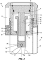
FIG. 3 is a partial cross-sectional view of the gas spring fastener driver ofFIG. 1 taken along lines 2-2 shown inFIG. 1 , illustrating a cylinder housing of the gas spring mechanism displaced away from the drive blade to reduce the pressure within the cylinder housing. -
FIG. 4 is a perspective view of a gas spring mechanism embodiment including a lever. -
FIG. 5 is a perspective view of a gas spring mechanism embodiment including a socket. - Before any embodiments of the invention are explained in detail, it is to be understood that the invention is not limited in its application to the details of construction and the arrangement of components set forth in the following description or illustrated in the following drawings. The invention is capable of other embodiments and of being practiced or of being carried out in various ways. Also, it is to be understood that the phraseology and terminology used herein is for the purpose of description and should not be regarded as limiting.
- With reference to
FIG. 1 , a gasspring fastener driver 10 for driving fasteners (e.g., nails, tacks, staples, etc.) into a workpiece is shown. Thefastener driver 10 includes amain housing 12, anosepiece 14 extending from the main housing, and amagazine 18 for sequentially feeding collated fasteners into thenosepiece 14 prior to each fastener-driving operation. Thefastener driver 10 also includes adrive blade 22, atip 26 of which is received within thenosepiece 14, and an onboardgas spring mechanism 30 for driving thedrive blade 22 from a retracted position (shown inFIG. 1 ) toward a driven position (not shown) coinciding with ejection of a fastener from thenosepiece 14. Accordingly, thefastener driver 10 does not require an external source of air pressure or other external power source for driving thedrive blade 22. - With reference to
FIG. 1 , thegas spring mechanism 30 includes acylinder housing 34 in which a pressurized gas (e.g., air) is stored in an internal chamber 35 (FIGS. 2 and3 ). Apiston 38 protrudes from thecylinder housing 34. The pressurized gas in thechamber 35 biases thepiston 38 toward a driven position (shown inFIG. 3 ) in which it is fully extended from thecylinder housing 34. In other words, thepiston 38 is movable relative to thecylinder housing 34 and is biased by the pressurized gas from the retracted position (FIGS. 1 and2 ) toward the driven position (FIG. 3 ). Thegas spring mechanism 30 further includes aguide post 39 that is seated within an upper end of thecylinder housing 34. Theguide post 39 is received within acorresponding bore 40 formed in thepiston 38 to maintain alignment of thepiston 38 as thepiston 38 translates between the retracted and driven positions. O-rings 41 are provided for sealing theinternal chamber 35 at theguide post 39 and thepiston 38. Thepiston 38 includes adistal end 42 against which ahead 46 of thedrive blade 22 is abuttable when thedrive blade 22 is in the retracted position (shown inFIG. 1 ). Movement of thedrive blade 22 is limited to axial reciprocation, between the retracted position and the driven position. For example, movement of thedrive blade 22 may be limited in this manner by one or more guide rails along which thehead 46 of thedrive blade 22 is slidable. - As explained in greater detail below, the
cylinder housing 34 is displaceable along alongitudinal axis 50 of thepiston 38 relative to themain housing 12 and away from thedrive blade 22. As thecylinder housing 34 is displaced, thepiston 38 remains stationary relative to themain housing 12, thereby enlarging the effective volume of thechamber 35 and consequently reducing the pressure of the pressurized gas within thechamber 35 of thecylinder housing 34. In the illustrated embodiment, thecylinder housing 34 includesexternal threads 45 on an outer periphery thereof that are engageable with matinginternal threads 44 of amount 43 that is stationary relative to themain housing 12. In some embodiments, thethreads 45 may extend along the entire length of thecylinder housing 34, and/or themain housing 12 andmount 43 may include mating threads along the entire lengths thereof to extend the range of adjustment of thecylinder housing 34. Thecylinder housing 34 is displaceable along thelongitudinal axis 50 in response to the rotation of thecylinder housing 34 relative to themount 43 andmain housing 12, for each complete revolution of thecylinder housing 34, by a distance dictated by the pitch of themated threads cylinder housing 34 translates along thelongitudinal axis 50 by a distance equal to the pitch of thetreads cylinder housing 34 relative to themain housing 12. In other words, a user rotates thecylinder housing 34 by manually gasping and rotating thecylinder housing 34. Additionally or alternatively, a lever 47 (FIG. 4 ) may be coupled to thecylinder housing 34 to increase the leverage that a user is able to apply to thecylinder housing 34, thereby increasing the amount of torque that can be applied to rotate thecylinder housing 34. Additionally, a socket 48 (FIG. 5 ) including a square, hex, or other cross-sectional shape may be formed on anaxial end 49 of thecylinder housing 34 to allow a user to utilize a hand or power tool to rotate thecylinder housing 34. As explained in greater detail below, it is desirable to displace thecylinder housing 34 with respect to themain housing 12 when thefastener tool 10 becomes jammed, locking thepiston 38 in place, to allow the user to de-energize thegas spring mechanism 30 before clearing the jam. Alternatively, thecylinder housing 34 may be displaceable along thelongitudinal axis 50 in response to rotation of themount 43 with respect to themain housing 12. - With reference to
FIG. 1 , thefastener driver 10 also includes a first return mechanism (i.e., an extensible cylinder 54) for raising thedrive blade 22 from the driven position toward the retracted position. In the illustrated embodiment of thefastener driver 10, theextensible cylinder 54 includes acylinder housing 58 affixed to themain housing 12 such that thecylinder housing 58 is stationary relative to themain housing 12 and thecylinder housing 34 of thegas spring mechanism 30. Thecylinder housing 58 of theextensible cylinder 54 may be affixed directly to themain housing 12. Alternatively, thecylinder housing 58 of theextensible cylinder 54 may be affixed to an intermediate component of thefastener driver 10 which, either directly or indirectly, is affixed to themain housing 12. - The
extensible cylinder 54 also includes arod 62 coupled to thehead 46 of thedrive blade 22 for movement with thedrive blade 22. In the illustrated embodiment of thefastener driver 10, therod 62 is abutted against a flange 66 (FIG. 1 ) extending in a lateral direction from alongitudinal axis 70 of thedrive blade 22, and secured to theflange 66 using a fastener (e.g., a screw). Alternatively, therod 62 may be affixed to thehead 46 of thedrive blade 22 using a welding process, adhesives, an interference fit, or by integrally forming, for example. Accordingly, therod 62 is axially movable between a retracted position coinciding with the retracted positions of thepiston 38 and the drive blade 22 (shown inFIG. 1 ), and an extended position coinciding with the driven position of the drive blade 22 (not shown). Alongitudinal axis 74 of theextensible cylinder 54, therefore, is oriented parallel with thelongitudinal axis 70 of thedrive blade 22. Alternatively, therod 62 may be coupled directly to themain housing 12, and thecylinder housing 58 of theextensible cylinder 54 may be affixed to thedrive blade 22. Thecylinder housing 58 of theextensible cylinder 54 includes an interior chamber in which therod 62 is slidable. A vacuum is created in thecylinder housing 58 for biasing therod 62 toward a retracted position. Alternatively, thecylinder housing 58 includes a pressurized gas biasing therod 62 toward the retracted position. - As is described in further detail below, between two consecutive firing operations of the
fastener driver 10, theextensible cylinder 54 returns or raises thedrive blade 22 from the driven position (coinciding with ejection of a fastener from the nosepiece 14) to a retracted position (shown inFIG. 1 ). Thefastener driver 10 further includes a second return mechanism (i.e., a lifter mechanism 98), that raises thepiston 38 from the driven position (FIG. 3 ) toward the retracted position (FIGS. 1 and2 ). The first andsecond return mechanisms drive blade 22 and thepiston 38 to their respective retracted positions. Returning both thedriver blade 22 and thepiston 38 to the retracted positions in parallel increases the speed at which fasteners may be driven (i.e., the cycle time is reduced). - In the illustrated embodiment of the
fastener driver 10 as shown inFIG. 1 , thelifter mechanism 98 includes anelectric motor 102 powered by an on-board power source (e.g., a battery), tworotatable cam lobes 106 mounted on acam shaft 107, and atransmission 110 interconnecting themotor 102 and thecam lobes 106. Thetransmission 110 includes aplanetary gear train 114 connected to an output shaft of themotor 102 and an offsetgear train 118 connected to the output of theplanetary gear train 114. Specifically, the offsetgear train 118 includes afirst gear 122 connected with the output of theplanetary gear train 114, asecond gear 126 enmeshed with thefirst gear 122 and connected with thecam shaft 107 andcam lobes 106. Accordingly, torque from themotor 102 is transferred through theplanetary gear train 114 and the offsetgear train 118, causing thecam lobes 106 to rotate about arotational axis 130 of thesecond gear 126, which is coaxial with thecam shaft 107. Thedrive blade 22 includes agroove 23 that receives thecam shaft 107, so thedrive blade 22 and thecam shaft 107 do not engage as thedrive blade 22 is moved toward its raised position by theextensible cylinder 54. A springloaded pin (not shown) abuts thecam lobes 106 to prevent thepiston 38 from back-driving thecam lobes 106 andmotor 102. - With continued reference to
FIG. 1 , thepiston 38 includes afollower 134 engaged with thecam lobes 106 while thepiston 38 is raised from the driven position to the retracted position. In the illustrated embodiment of thefastener driver 10, thefollower 134 is configured as a cylindrical pin that is slidable along the outer periphery of thecam lobes 106 in response to rotation of thecam lobes 106. In other words, thefollower 134 is positioned between thecam lobes 106 and thepiston 38. Thefollower 134 is coupled for movement with thepiston 38 between the driven and retracted positions of thepiston 38. Furthermore, thefollower 134 protrudes from thepiston 38 in a lateral (i.e., transverse) direction relative to the longitudinal axis of the piston 38 (which in the illustrated embodiment is coaxial with thelongitudinal axis 70 of the driver blade 22), and thecam lobes 106 are positioned on either side of both thedrive blade 22 and thepiston 38. - In operation of the
fastener driver 10, a first firing operation is commenced by the user depressing a trigger (not shown) of thefastener driver 10. Prior to pulling the trigger, thedrive blade 22 and thepiston 38 are held in their retracted positions, respectively, by theextensible cylinder 54 and the cam lobes 106 (shown inFIG. 1 ). Shortly after the trigger being depressed, themotor 102 is activated to rotate thecam lobes 106 in a counter-clockwise direction about therotational axis 130 from the frame of reference ofFIG. 1 . - Upon the
follower 134 sliding off the tip of thecam lobes 106, the pressurized gas within thecylinder housing 34 expands, pushing thepiston 38 outward from thecylinder housing 34 and accelerating thedrive blade 22 toward its driven position. The cam lobes 106 are accelerated to a sufficient rotational speed to prohibit subsequent contact with thefollower 134 as thepiston 38 is being driven from its retracted position to the driven position. In addition, the timing of thepiston 38 reaching an intermediate position coincides with thefollower 134 passing alongside aflat segment 138 of thecam lobes 106, thereby creating an unobstructed path for thefollower 134 as thepiston 38 is displaced from its retracted position toward its driven position. - After the
piston 38 reaches its driven position, thehead 46 of thedrive blade 22 separates from thedistal end 42 of thepiston 38, ceasing further acceleration of thedrive blade 22. Thereafter, thedrive blade 22 continues moving toward its driven position at a relatively constant velocity. Upon impact with a fastener in thenosepiece 14, thedrive blade 22 begins to decelerate, ultimately being stopped after the fastener is driven into a workpiece. - During the period of movement of the
drive blade 22 from its retracted position to its driven position, because therod 62 of theextensible cylinder 54 is affixed to thehead 46 of thedrive blade 22 for movement therewith, therod 62 is also pulled from thecylinder housing 58. As therod 62 is pulled from thecylinder housing 58, a vacuum is created within thecylinder housing 58. After movement of thedrive blade 22 is stopped following the conclusion of the first firing operation, a pressure imbalance applies a force on therod 62, causing it to retract into thecylinder housing 58. Because therod 62 is affixed to thehead 46 of thedrive blade 22, thedrive blade 22 is raised from its driven position toward the retracted position. As stated earlier, a pressurized gas within theextensible cylinder 54 may alternatively be utilized to raise thedrive blade 22 from its driven position toward the retracted position. - Coinciding with the
drive blade 22 rising toward the retracted position, rotation of the cam lobes 106 (in the same counter-clockwise direction) is resumed (or alternatively accelerated if previously slowed) to once again contact thefollower 134. As thecam lobes 106 continue their rotation, thefollower 134 and thepiston 38 are displaced upward from the driven position toward the retracted position shown inFIG. 1 . The cam lobes 106 continue to raise thepiston 38 and theextensible cylinder 54 continues to raise thedrive blade 22, in parallel, until both reach their retracted positions shown inFIG. 1 , at which time the first firing operation is completed. Thereafter, additional firing operations may be initiated in a like manner. - In an alternative firing cycle, the
lifter mechanism 98 may remain deactivated after theextensible cylinder 54 has returned thedrive blade 22 to its rest or intermediate position, thereby maintaining thepiston 38 in its driven position, until the user depresses the trigger to initiate a firing operation. This way, thegas spring mechanism 30 remains in a deactivated state (i.e., with thepiston 38 in its biased, driven position) when thefastener driver 10 is not in use. - By providing the
extensible cylinder 54 to return thedrive blade 22 to its retracted position following each fastener firing operation (i.e., as opposed to using thelifter mechanism 98 to raise thedrive blade 22 from its driven position to its retracted position), the cycle time between consecutive firing operations may be reduced, allowing for more rapid placement of fasteners into a workpiece. - With reference to
FIG. 2 , when a jam occurs in thefastener tool 10 thepiston 38 may become stuck in the retracted position shown (i.e., an energized state). For example, rotation of thecam lobes 106 may be stopped before thefollower 134 slides off the tip of thecam lobes 106. With thepiston 38 stuck in the position shown inFIG. 2 , the pressurized gas within thecylinder housing 34 continues to bias thepiston 38 outward from thecylinder housing 34. Should the jam become clear, the energized state of thegas spring mechanism 30 may unintentionally urge thepiston 38 to the driven position. As such, it is desirable to release the stored energy within thegas spring mechanism 30 when a jam occurs to de-energize the system before the jam is removed (i.e., cleared). - To release the stored energy within the
gas spring mechanism 30 prior to clearing a jam, the user rotates thecylinder housing 34 relative to themain housing 12, causing thecylinder housing 34 to translate along thelongitudinal axis 50 and away from the drive blade 22 (for each complete revolution of the cylinder housing 34) by a distance dictated by the pitch of thethreads cylinder housing 34 is displaced, thepiston 38 remains stationary relative to themain housing 12, enlarging the effective volume of thechamber 35 and consequently reducing the pressure of the pressurized gas within thecylinder housing 34. Said another way, rotation of thecylinder housing 34 by a user causes thecylinder housing 34 to move away from thepiston 38 such that the volume within thecylinder housing 34 is increased and the pressure is reduced. With thegas spring mechanism 30 in the de-energized state ofFIG. 3 , there is no risk of thepiston 38 inadvertently and unexpectedly moving to its driven position once the jam is cleared because thepiston 38 is already in the driven position. - Upon the
cylinder housing 34 reaching the position shown inFIG. 3 in which thegas spring mechanism 30 is de-energized, a position or proximity sensor (not shown) is triggered, thereby prompting a master control unit (also not shown) to activate themotor 102 to incrementally rotate thecam lobes 106 out of the way of thefollower 134. With thecam lobes 106 disengaged from and misaligned with thefollower 134, thecylinder housing 34 can be rotated by a user in an opposite direction to return thecylinder housing 34 to the position shown inFIG. 2 , toward thedrive blade 22 with thepiston 38 in the driven position, without concern for thefollower 134 contacting thecam lobes 106 and compressing thepiston 38. In other words, thecylinder housing 34 and thepiston 38 may be translated together toward thedrive blade 22 without needing to displace thepiston 38 with respect to thecylinder housing 34. - Alternatively, the user may simply reverse the rotation of the
cylinder housing 34 by hand, without using tools, and without first moving thecam lobes 106 out of contact with thefollower 134. Thethreads mount 43 andcylinder housing 34 provide the user enough leverage to translate thecylinder housing 34 while thepiston 38 remains stationary to re-energize thegas spring mechanism 30. In other words, thethreads cylinder housing 34 to translate with respect to thepiston 38 in order to increase the pressure within thegas spring mechanism 30. Specifically, the diameter of the screw and pitch of thethreads gas spring mechanism 30. - Additionally or alternatively, adjusting the position of the
cylinder housing 34 along thelongitudinal axis 50 relative to themain housing 12 can adjust the depth to which a fastener is driven into a workpiece. Specifically, moving thecylinder housing 34 farther from the drive blade 22 (and allowing thepiston 38 to partially extend from thecylinder housing 34 prior to initiating a fastener firing operation) reduces the amount of force that can be generated by thegas spring mechanism 30 and applied to thepiston 38. Therefore, as the force applied to thepiston 38 is reduced, the lower the depth to which a fastener may be driven into a workpiece during a fastener firing operation. Thethreads cylinder housing 34 at any location along theaxis 50 where thethreads cylinder housing 34 would remain in position while operating thefastener driver 10. Essentially, thethreads cylinder housing 34 by thepiston 38. Alternatively, a detent system 142 (FIGS. 2 and3 ) may be used instead of relying upon the threads to self-lock. Such adetent system 142 may include a spring-biased detent carried by thecylinder housing 34 or themain housing 12/mount 43 and a series of recesses in the other of thecylinder housing 34 or themain housing 12/mount 43 in which the detent is receivable to positively secure thecylinder housing 34 in a particular axial position along theaxis 50 relative to themain housing 12/mount 43. - Various features of the invention are set forth in the following claims.
Claims (15)
- A fastener driver (10) comprising:a main housing (12);a drive blade (22) movable from a retracted position to a driven position for driving a fastener into a workpiece;a gas spring mechanism (30) for driving the drive blade (22) from the retracted position to the driven position, the gas spring mechanism (30) includinga cylinder housing (34) containing a pressurized gas, anda piston (38) protruding from the cylinder housing (34), movable relative to the cylinder housing (34) and biased by the pressurized gas from a retracted position toward a driven position in which the piston (38) is fully extended from the cylinder housing (34);wherein the cylinder housing (34) is displaceable along a longitudinal axis (50) of the piston (38) relative to the main housing (12) and away from the drive blade (22), while the piston (38) remains stationary relative to the main housing (12), to reduce the pressure of the pressurized gas within the cylinder housing.
- The fastener driver (10) of claim 1, wherein the cylinder housing (34) includes external threads (45) on an outer periphery thereof engageable with mating internal threads (44) that are stationary relative to the main housing (12).
- The fastener driver (10) of claim 2, wherein the cylinder housing (34) is displaceable along the longitudinal axis (50) in response to rotation of the cylinder housing (34) relative to the main housing (12), optionally wherein the cylinder housing translates along the longitudinal axis by a distance equal to a pitch of the external threads in response to a complete rotation of the cylinder housing relative to the main housing.
- The fastener driver (10) of claim 2, wherein the external threads (45) are self-locking with the internal threads (44).
- The fastener driver (10) of any one of claims 1 to 4, further comprising a lever (47) coupled to the cylinder housing (34), wherein the lever (47) is graspable by a user to rotate the cylinder housing (34).
- The fastener driver (10) of any one of claims 1 to 4, wherein the cylinder housing (34) includes an axial end (49) formed with a socket (48).
- The fastener driver (10) of any one of claims 1 to 6, further comprising a first return mechanism (54) for returning the drive blade (22) from the driven position toward the retracted position.
- The fastener driver (10) of claim 7, wherein the first return mechanism (54) includes an extensible cylinder.
- The fastener driver (10) of claim 7 or 8, further comprising a second return mechanism (98) for returning the piston (38) from the driven position toward the retracted position.
- The fastener driver (10) of claim 9, wherein the first return mechanism (54) and the second return mechanism (98) operate in parallel to return the drive blade (22) and the piston (38) to the respective retracted positions.
- The fastener driver (10) of claim 9 or 10, wherein the fastener driver (10) further comprises a sensor configured to detect the position of the cylinder housing (34) with respect to the main housing (12), and in response to the sensor detecting the cylinder housing (34) is a predetermined distance away from the main housing (12), the second return mechanism (98) is energized.
- The fastener driver (10) of claim 1, wherein the depth to which the fastener is driven by the drive blade (22) is adjusted by displacing the cylinder housing (34) along the longitudinal axis (50) of the piston (38) relative to the main housing (12).
- The fastener driver (10) of claim 1, further comprising a detent system (142) to selectively secure the cylinder housing (34) in a particular position relative to the main housing (12).
- The fastener driver (10) of claim 1, wherein the gas spring mechanism (30) further comprises a guide post (39) positioned within the cylinder housing (34), and wherein the guide post (39) is received within a corresponding bore (40) formed in the piston (38).
- A method of clearing a jammed fastener in the fastener driver (10) of any one of claims 1 to 14, the method comprising:moving the cylinder housing (34) of the gas spring mechanism (30) from a first position to a second position, thereby reducing the pressure within the gas spring mechanism (30);clearing the jammed fastener; andreturning the cylinder housing (34) of the gas spring mechanism (30) from the second position back to the first position, thereby increasing the pressure within the gas spring mechanism (30).
Applications Claiming Priority (1)
| Application Number | Priority Date | Filing Date | Title |
|---|---|---|---|
| US201662352630P | 2016-06-21 | 2016-06-21 |
Publications (3)
| Publication Number | Publication Date |
|---|---|
| EP3263285A2 EP3263285A2 (en) | 2018-01-03 |
| EP3263285A3 EP3263285A3 (en) | 2018-07-18 |
| EP3263285B1 true EP3263285B1 (en) | 2020-01-15 |
Family
ID=59101372
Family Applications (1)
| Application Number | Title | Priority Date | Filing Date |
|---|---|---|---|
| EP17177241.1A Active EP3263285B1 (en) | 2016-06-21 | 2017-06-21 | Gas spring fastener driver |
Country Status (5)
| Country | Link |
|---|---|
| US (1) | US11400574B2 (en) |
| EP (1) | EP3263285B1 (en) |
| CN (1) | CN107520820B (en) |
| AU (1) | AU2017204205B2 (en) |
| CA (1) | CA2971465C (en) |
Families Citing this family (7)
| Publication number | Priority date | Publication date | Assignee | Title |
|---|---|---|---|---|
| TWI744560B (en) * | 2017-11-02 | 2021-11-01 | 鑽全實業股份有限公司 | Pneumatic nail gun and its firing pin device |
| US11358262B2 (en) * | 2018-10-24 | 2022-06-14 | Tricord Solutions, Inc. | Fastener driving apparatus |
| CN109176411B (en) * | 2018-11-13 | 2024-03-29 | 久维科技(苏州)有限公司 | Quick fastening device |
| EP3670094A1 (en) * | 2018-12-20 | 2020-06-24 | Hilti Aktiengesellschaft | Driving device |
| US11260513B2 (en) * | 2019-09-13 | 2022-03-01 | Klein Tools, Inc. | Powered fastening device with depth shutoff |
| EP4117863A4 (en) | 2020-03-13 | 2024-03-27 | Black & Decker Inc | Pipe clamp, pipe clamp driver and anti-backdrive mechanism |
| CN114102519B (en) * | 2021-12-06 | 2023-10-27 | 杭州银湖机械弹簧有限公司 | Experimental verification's wood structure spring erection equipment |
Family Cites Families (50)
| Publication number | Priority date | Publication date | Assignee | Title |
|---|---|---|---|---|
| US2944522A (en) | 1957-02-25 | 1960-07-12 | Fastener Corp | Fastener driving apparatus |
| US2946313A (en) * | 1958-02-03 | 1960-07-26 | Powers Wire Products Company I | Fastener driving tool and release therefor |
| US3190189A (en) | 1963-10-03 | 1965-06-22 | Fastener Corp | Fastener driving apparatus |
| US3278103A (en) | 1965-04-06 | 1966-10-11 | Senco Products | Fastener applying device |
| US3871566A (en) | 1972-07-25 | 1975-03-18 | Behrens Friedrich Joh | Fastener driver tools |
| US3858780A (en) | 1973-01-08 | 1975-01-07 | Spotnails | Fastener-driving tool |
| US3809307A (en) | 1973-02-23 | 1974-05-07 | Fastener Corp | Safety assembly for fastener driving tool |
| US3940044A (en) | 1974-10-15 | 1976-02-24 | Parker Manufacturing Company | Fastener driver with safety device |
| US3948426A (en) | 1975-01-20 | 1976-04-06 | Parker Manufacturing Co. | Fastener driver with safety device |
| DE2651529A1 (en) | 1976-11-11 | 1978-05-18 | Hilti Ag | COMPRESSED AIR SETTING DEVICE |
| US4122904A (en) | 1977-01-27 | 1978-10-31 | Pneutek, Inc. | Pneumatic hammer driver |
| US4339065A (en) | 1978-07-24 | 1982-07-13 | Haytayan Harry M | Pneumatic tool |
| US4227637A (en) | 1978-11-30 | 1980-10-14 | Haytayan Harry M | Pneumatic fastening tool |
| US4215808A (en) | 1978-12-22 | 1980-08-05 | Sollberger Roger W | Portable electric fastener driving apparatus |
| JPS601153B2 (en) | 1979-02-28 | 1985-01-12 | マックス株式会社 | Safety devices for pneumatically driven impact tools |
| US4260092A (en) | 1979-07-02 | 1981-04-07 | Duo-Fast Corporation | Safety assembly for a tool for driving fasteners |
| US4346831A (en) | 1980-01-09 | 1982-08-31 | Haytayan Harry M | Pneumatic fastening tools |
| DE3014803C2 (en) * | 1980-04-17 | 1985-07-25 | Joh. Friedrich Behrens AG, 2070 Ahrensburg | Pneumatic nailer |
| IN157475B (en) | 1981-01-22 | 1986-04-05 | Signode Corp | |
| US4452387A (en) | 1982-04-15 | 1984-06-05 | Pneutek, Inc. | Self-centering fastening tool |
| SE462470B (en) | 1987-08-13 | 1990-07-02 | Kihlberg Ab Josef | DEVICE FOR APPLIANCE FOR DRIVING MEDIUM PRESSURE AIR |
| US4909419A (en) | 1987-11-05 | 1990-03-20 | Max Co., Ltd. | Percussion tool |
| US4821938A (en) | 1987-11-25 | 1989-04-18 | Haytayan Harry M | Powder-actuated fastener driving tool |
| EP0336021B1 (en) | 1988-04-07 | 1994-07-06 | Umberto Monacelli | Pneumatic powered fastener device |
| US5511715A (en) | 1993-02-03 | 1996-04-30 | Sencorp | Flywheel-driven fastener driving tool and drive unit |
| AU667162B2 (en) | 1993-05-13 | 1996-03-07 | Stanley-Bostitch, Inc. | Fastener driving device particularly suited for use as a roofing nailer |
| US6123241A (en) | 1995-05-23 | 2000-09-26 | Applied Tool Development Corporation | Internal combustion powered tool |
| JP3676879B2 (en) | 1995-07-25 | 2005-07-27 | 株式会社マキタ | Fastener driving tool |
| US5645208A (en) | 1995-10-17 | 1997-07-08 | Haytayan; Harry M. | Pneumatic fastening tool with safety interlock |
| EP0774325B1 (en) | 1995-11-20 | 2002-06-26 | Max Co., Ltd. | Screw driving and turning machine |
| US6145724A (en) | 1997-10-31 | 2000-11-14 | Illinois Tool Works, Inc. | Combustion powered tool with combustion chamber delay |
| AU761377B2 (en) | 1999-04-05 | 2003-06-05 | Stanley Fastening Systems, L.P. | Safety trip assembly and trip lock mechanism for a fastener driving tool |
| US7156012B2 (en) | 2004-01-20 | 2007-01-02 | Hitachi Koki Co., Ltd. | Pneumatically operated fastener driving tool |
| TWI273955B (en) | 2004-02-20 | 2007-02-21 | Black & Decker Inc | Dual mode pneumatic fastener actuation mechanism |
| JP4570893B2 (en) | 2004-03-31 | 2010-10-27 | 日本パワーファスニング株式会社 | Portable fastener driving tool |
| US7213732B2 (en) | 2004-04-02 | 2007-05-08 | Black & Decker Inc. | Contact trip mechanism for nailer |
| JP4380395B2 (en) | 2004-04-05 | 2009-12-09 | 日立工機株式会社 | Combustion power tool |
| JP4877457B2 (en) | 2005-05-17 | 2012-02-15 | マックス株式会社 | Nail feed delay mechanism for gas fired driving tools |
| DE102005000062A1 (en) | 2005-05-18 | 2006-11-23 | Hilti Ag | Electrically operated tacker |
| JP4720656B2 (en) | 2006-07-12 | 2011-07-13 | 日立工機株式会社 | Driving machine |
| TWI319740B (en) | 2006-08-30 | 2010-01-21 | Air actuated nail driver | |
| US8875969B2 (en) | 2007-02-09 | 2014-11-04 | Tricord Solutions, Inc. | Fastener driving apparatus |
| US8011547B2 (en) | 2007-10-05 | 2011-09-06 | Senco Brands, Inc. | Fastener driving tool using a gas spring |
| US8763874B2 (en) | 2007-10-05 | 2014-07-01 | Senco Brands, Inc. | Gas spring fastener driving tool with improved lifter and latch mechanisms |
| CN202129781U (en) | 2011-06-03 | 2012-02-01 | 博世电动工具(中国)有限公司 | Functional module and power nailing machine with same |
| DE102012219288A1 (en) * | 2012-10-23 | 2014-04-24 | Hilti Aktiengesellschaft | Drive-in device with adjustable spring accumulator |
| WO2015024398A1 (en) | 2013-08-22 | 2015-02-26 | Techtronic Power Tools Technology Limited | Pneumatic fastener driver |
| US9539714B1 (en) | 2014-10-07 | 2017-01-10 | Tricord Solutions, Inc. | Fastener driving apparatus |
| WO2016160699A1 (en) | 2015-03-30 | 2016-10-06 | Senco Brands, Inc. | Lift mechanism for framing nailer |
| US20170274513A1 (en) * | 2016-03-28 | 2017-09-28 | Tricord Solutions, Inc. | Fastener driving apparatus |
-
2017
- 2017-06-20 US US15/627,737 patent/US11400574B2/en active Active
- 2017-06-21 CA CA2971465A patent/CA2971465C/en active Active
- 2017-06-21 EP EP17177241.1A patent/EP3263285B1/en active Active
- 2017-06-21 AU AU2017204205A patent/AU2017204205B2/en active Active
- 2017-06-21 CN CN201710480045.7A patent/CN107520820B/en active Active
Non-Patent Citations (1)
| Title |
|---|
| None * |
Also Published As
| Publication number | Publication date |
|---|---|
| CA2971465A1 (en) | 2017-12-21 |
| US11400574B2 (en) | 2022-08-02 |
| EP3263285A2 (en) | 2018-01-03 |
| AU2017204205A1 (en) | 2018-01-18 |
| CN107520820B (en) | 2021-10-01 |
| EP3263285A3 (en) | 2018-07-18 |
| CN107520820A (en) | 2017-12-29 |
| US20170361441A1 (en) | 2017-12-21 |
| AU2017204205B2 (en) | 2018-12-20 |
| CA2971465C (en) | 2022-11-08 |
Similar Documents
| Publication | Publication Date | Title |
|---|---|---|
| EP3263285B1 (en) | Gas spring fastener driver | |
| US11110576B2 (en) | Gas spring fastener driver | |
| CA2969392C (en) | Gas spring fastener driver | |
| US11590638B2 (en) | Driver | |
| US7806198B2 (en) | Hybrid impact tool | |
| EP1851010B1 (en) | Nail advancement systems for nail arrays disposed within nailing tool magazines | |
| EP3131708B1 (en) | Fastener-driving tool including a driving device | |
| EP3036069B1 (en) | Pneumatic fastener driver | |
| CA2672308A1 (en) | Cordless fastener tool with fastener driving and rotating functions | |
| US10058987B2 (en) | Hand-held power tool | |
| EP2944427B1 (en) | Motor-driven fastening tool | |
| EP3325217B1 (en) | Fastener driving apparatus | |
| WO2023250350A1 (en) | Fastening tool having position biased release valve |
Legal Events
| Date | Code | Title | Description |
|---|---|---|---|
| PUAI | Public reference made under article 153(3) epc to a published international application that has entered the european phase |
Free format text: ORIGINAL CODE: 0009012 |
|
| STAA | Information on the status of an ep patent application or granted ep patent |
Free format text: STATUS: THE APPLICATION HAS BEEN PUBLISHED |
|
| AK | Designated contracting states |
Kind code of ref document: A2 Designated state(s): AL AT BE BG CH CY CZ DE DK EE ES FI FR GB GR HR HU IE IS IT LI LT LU LV MC MK MT NL NO PL PT RO RS SE SI SK SM TR |
|
| AX | Request for extension of the european patent |
Extension state: BA ME |
|
| PUAL | Search report despatched |
Free format text: ORIGINAL CODE: 0009013 |
|
| AK | Designated contracting states |
Kind code of ref document: A3 Designated state(s): AL AT BE BG CH CY CZ DE DK EE ES FI FR GB GR HR HU IE IS IT LI LT LU LV MC MK MT NL NO PL PT RO RS SE SI SK SM TR |
|
| AX | Request for extension of the european patent |
Extension state: BA ME |
|
| RIC1 | Information provided on ipc code assigned before grant |
Ipc: B25C 1/06 20060101ALI20180608BHEP Ipc: B25C 1/04 20060101AFI20180608BHEP |
|
| RIN1 | Information on inventor provided before grant (corrected) |
Inventor name: NAMOUZ, ESSAM |
|
| STAA | Information on the status of an ep patent application or granted ep patent |
Free format text: STATUS: REQUEST FOR EXAMINATION WAS MADE |
|
| 17P | Request for examination filed |
Effective date: 20190102 |
|
| RBV | Designated contracting states (corrected) |
Designated state(s): AL AT BE BG CH CY CZ DE DK EE ES FI FR GB GR HR HU IE IS IT LI LT LU LV MC MK MT NL NO PL PT RO RS SE SI SK SM TR |
|
| GRAP | Despatch of communication of intention to grant a patent |
Free format text: ORIGINAL CODE: EPIDOSNIGR1 |
|
| STAA | Information on the status of an ep patent application or granted ep patent |
Free format text: STATUS: GRANT OF PATENT IS INTENDED |
|
| INTG | Intention to grant announced |
Effective date: 20190909 |
|
| GRAS | Grant fee paid |
Free format text: ORIGINAL CODE: EPIDOSNIGR3 |
|
| GRAA | (expected) grant |
Free format text: ORIGINAL CODE: 0009210 |
|
| STAA | Information on the status of an ep patent application or granted ep patent |
Free format text: STATUS: THE PATENT HAS BEEN GRANTED |
|
| AK | Designated contracting states |
Kind code of ref document: B1 Designated state(s): AL AT BE BG CH CY CZ DE DK EE ES FI FR GB GR HR HU IE IS IT LI LT LU LV MC MK MT NL NO PL PT RO RS SE SI SK SM TR |
|
| REG | Reference to a national code |
Ref country code: CH Ref legal event code: EP Ref country code: GB Ref legal event code: FG4D |
|
| REG | Reference to a national code |
Ref country code: IE Ref legal event code: FG4D |
|
| REG | Reference to a national code |
Ref country code: DE Ref legal event code: R096 Ref document number: 602017010844 Country of ref document: DE |
|
| REG | Reference to a national code |
Ref country code: AT Ref legal event code: REF Ref document number: 1224739 Country of ref document: AT Kind code of ref document: T Effective date: 20200215 |
|
| RAP2 | Party data changed (patent owner data changed or rights of a patent transferred) |
Owner name: TTI (MACAO COMMERCIAL OFFSHORE) LIMITED |
|
| REG | Reference to a national code |
Ref country code: NL Ref legal event code: MP Effective date: 20200115 |
|
| REG | Reference to a national code |
Ref country code: LT Ref legal event code: MG4D |
|
| PG25 | Lapsed in a contracting state [announced via postgrant information from national office to epo] |
Ref country code: NL Free format text: LAPSE BECAUSE OF FAILURE TO SUBMIT A TRANSLATION OF THE DESCRIPTION OR TO PAY THE FEE WITHIN THE PRESCRIBED TIME-LIMIT Effective date: 20200115 Ref country code: PT Free format text: LAPSE BECAUSE OF FAILURE TO SUBMIT A TRANSLATION OF THE DESCRIPTION OR TO PAY THE FEE WITHIN THE PRESCRIBED TIME-LIMIT Effective date: 20200607 Ref country code: NO Free format text: LAPSE BECAUSE OF FAILURE TO SUBMIT A TRANSLATION OF THE DESCRIPTION OR TO PAY THE FEE WITHIN THE PRESCRIBED TIME-LIMIT Effective date: 20200415 Ref country code: FI Free format text: LAPSE BECAUSE OF FAILURE TO SUBMIT A TRANSLATION OF THE DESCRIPTION OR TO PAY THE FEE WITHIN THE PRESCRIBED TIME-LIMIT Effective date: 20200115 Ref country code: RS Free format text: LAPSE BECAUSE OF FAILURE TO SUBMIT A TRANSLATION OF THE DESCRIPTION OR TO PAY THE FEE WITHIN THE PRESCRIBED TIME-LIMIT Effective date: 20200115 |
|
| PG25 | Lapsed in a contracting state [announced via postgrant information from national office to epo] |
Ref country code: LV Free format text: LAPSE BECAUSE OF FAILURE TO SUBMIT A TRANSLATION OF THE DESCRIPTION OR TO PAY THE FEE WITHIN THE PRESCRIBED TIME-LIMIT Effective date: 20200115 Ref country code: SE Free format text: LAPSE BECAUSE OF FAILURE TO SUBMIT A TRANSLATION OF THE DESCRIPTION OR TO PAY THE FEE WITHIN THE PRESCRIBED TIME-LIMIT Effective date: 20200115 Ref country code: HR Free format text: LAPSE BECAUSE OF FAILURE TO SUBMIT A TRANSLATION OF THE DESCRIPTION OR TO PAY THE FEE WITHIN THE PRESCRIBED TIME-LIMIT Effective date: 20200115 Ref country code: GR Free format text: LAPSE BECAUSE OF FAILURE TO SUBMIT A TRANSLATION OF THE DESCRIPTION OR TO PAY THE FEE WITHIN THE PRESCRIBED TIME-LIMIT Effective date: 20200416 Ref country code: IS Free format text: LAPSE BECAUSE OF FAILURE TO SUBMIT A TRANSLATION OF THE DESCRIPTION OR TO PAY THE FEE WITHIN THE PRESCRIBED TIME-LIMIT Effective date: 20200515 Ref country code: BG Free format text: LAPSE BECAUSE OF FAILURE TO SUBMIT A TRANSLATION OF THE DESCRIPTION OR TO PAY THE FEE WITHIN THE PRESCRIBED TIME-LIMIT Effective date: 20200415 |
|
| REG | Reference to a national code |
Ref country code: DE Ref legal event code: R097 Ref document number: 602017010844 Country of ref document: DE |
|
| PG25 | Lapsed in a contracting state [announced via postgrant information from national office to epo] |
Ref country code: SK Free format text: LAPSE BECAUSE OF FAILURE TO SUBMIT A TRANSLATION OF THE DESCRIPTION OR TO PAY THE FEE WITHIN THE PRESCRIBED TIME-LIMIT Effective date: 20200115 Ref country code: SM Free format text: LAPSE BECAUSE OF FAILURE TO SUBMIT A TRANSLATION OF THE DESCRIPTION OR TO PAY THE FEE WITHIN THE PRESCRIBED TIME-LIMIT Effective date: 20200115 Ref country code: LT Free format text: LAPSE BECAUSE OF FAILURE TO SUBMIT A TRANSLATION OF THE DESCRIPTION OR TO PAY THE FEE WITHIN THE PRESCRIBED TIME-LIMIT Effective date: 20200115 Ref country code: EE Free format text: LAPSE BECAUSE OF FAILURE TO SUBMIT A TRANSLATION OF THE DESCRIPTION OR TO PAY THE FEE WITHIN THE PRESCRIBED TIME-LIMIT Effective date: 20200115 Ref country code: CZ Free format text: LAPSE BECAUSE OF FAILURE TO SUBMIT A TRANSLATION OF THE DESCRIPTION OR TO PAY THE FEE WITHIN THE PRESCRIBED TIME-LIMIT Effective date: 20200115 Ref country code: RO Free format text: LAPSE BECAUSE OF FAILURE TO SUBMIT A TRANSLATION OF THE DESCRIPTION OR TO PAY THE FEE WITHIN THE PRESCRIBED TIME-LIMIT Effective date: 20200115 Ref country code: ES Free format text: LAPSE BECAUSE OF FAILURE TO SUBMIT A TRANSLATION OF THE DESCRIPTION OR TO PAY THE FEE WITHIN THE PRESCRIBED TIME-LIMIT Effective date: 20200115 Ref country code: DK Free format text: LAPSE BECAUSE OF FAILURE TO SUBMIT A TRANSLATION OF THE DESCRIPTION OR TO PAY THE FEE WITHIN THE PRESCRIBED TIME-LIMIT Effective date: 20200115 |
|
| REG | Reference to a national code |
Ref country code: AT Ref legal event code: MK05 Ref document number: 1224739 Country of ref document: AT Kind code of ref document: T Effective date: 20200115 |
|
| RAP2 | Party data changed (patent owner data changed or rights of a patent transferred) |
Owner name: TTI (MACAO COMMERCIAL OFFSHORE) LIMITED |
|
| PLBE | No opposition filed within time limit |
Free format text: ORIGINAL CODE: 0009261 |
|
| STAA | Information on the status of an ep patent application or granted ep patent |
Free format text: STATUS: NO OPPOSITION FILED WITHIN TIME LIMIT |
|
| 26N | No opposition filed |
Effective date: 20201016 |
|
| PG25 | Lapsed in a contracting state [announced via postgrant information from national office to epo] |
Ref country code: MC Free format text: LAPSE BECAUSE OF FAILURE TO SUBMIT A TRANSLATION OF THE DESCRIPTION OR TO PAY THE FEE WITHIN THE PRESCRIBED TIME-LIMIT Effective date: 20200115 Ref country code: AT Free format text: LAPSE BECAUSE OF FAILURE TO SUBMIT A TRANSLATION OF THE DESCRIPTION OR TO PAY THE FEE WITHIN THE PRESCRIBED TIME-LIMIT Effective date: 20200115 Ref country code: IT Free format text: LAPSE BECAUSE OF FAILURE TO SUBMIT A TRANSLATION OF THE DESCRIPTION OR TO PAY THE FEE WITHIN THE PRESCRIBED TIME-LIMIT Effective date: 20200115 |
|
| REG | Reference to a national code |
Ref country code: CH Ref legal event code: PL |
|
| PG25 | Lapsed in a contracting state [announced via postgrant information from national office to epo] |
Ref country code: SI Free format text: LAPSE BECAUSE OF FAILURE TO SUBMIT A TRANSLATION OF THE DESCRIPTION OR TO PAY THE FEE WITHIN THE PRESCRIBED TIME-LIMIT Effective date: 20200115 Ref country code: PL Free format text: LAPSE BECAUSE OF FAILURE TO SUBMIT A TRANSLATION OF THE DESCRIPTION OR TO PAY THE FEE WITHIN THE PRESCRIBED TIME-LIMIT Effective date: 20200115 |
|
| PG25 | Lapsed in a contracting state [announced via postgrant information from national office to epo] |
Ref country code: LU Free format text: LAPSE BECAUSE OF NON-PAYMENT OF DUE FEES Effective date: 20200621 |
|
| REG | Reference to a national code |
Ref country code: BE Ref legal event code: MM Effective date: 20200630 |
|
| PG25 | Lapsed in a contracting state [announced via postgrant information from national office to epo] |
Ref country code: CH Free format text: LAPSE BECAUSE OF NON-PAYMENT OF DUE FEES Effective date: 20200630 Ref country code: LI Free format text: LAPSE BECAUSE OF NON-PAYMENT OF DUE FEES Effective date: 20200630 Ref country code: IE Free format text: LAPSE BECAUSE OF NON-PAYMENT OF DUE FEES Effective date: 20200621 |
|
| PG25 | Lapsed in a contracting state [announced via postgrant information from national office to epo] |
Ref country code: BE Free format text: LAPSE BECAUSE OF NON-PAYMENT OF DUE FEES Effective date: 20200630 |
|
| PG25 | Lapsed in a contracting state [announced via postgrant information from national office to epo] |
Ref country code: TR Free format text: LAPSE BECAUSE OF FAILURE TO SUBMIT A TRANSLATION OF THE DESCRIPTION OR TO PAY THE FEE WITHIN THE PRESCRIBED TIME-LIMIT Effective date: 20200115 Ref country code: MT Free format text: LAPSE BECAUSE OF FAILURE TO SUBMIT A TRANSLATION OF THE DESCRIPTION OR TO PAY THE FEE WITHIN THE PRESCRIBED TIME-LIMIT Effective date: 20200115 Ref country code: CY Free format text: LAPSE BECAUSE OF FAILURE TO SUBMIT A TRANSLATION OF THE DESCRIPTION OR TO PAY THE FEE WITHIN THE PRESCRIBED TIME-LIMIT Effective date: 20200115 |
|
| PG25 | Lapsed in a contracting state [announced via postgrant information from national office to epo] |
Ref country code: MK Free format text: LAPSE BECAUSE OF FAILURE TO SUBMIT A TRANSLATION OF THE DESCRIPTION OR TO PAY THE FEE WITHIN THE PRESCRIBED TIME-LIMIT Effective date: 20200115 Ref country code: AL Free format text: LAPSE BECAUSE OF FAILURE TO SUBMIT A TRANSLATION OF THE DESCRIPTION OR TO PAY THE FEE WITHIN THE PRESCRIBED TIME-LIMIT Effective date: 20200115 |
|
| PGFP | Annual fee paid to national office [announced via postgrant information from national office to epo] |
Ref country code: FR Payment date: 20230626 Year of fee payment: 7 Ref country code: DE Payment date: 20230626 Year of fee payment: 7 |
|
| PGFP | Annual fee paid to national office [announced via postgrant information from national office to epo] |
Ref country code: GB Payment date: 20230627 Year of fee payment: 7 |