EP3263264A1 - Electrochemical machining device and electrochemical machining method - Google Patents
Electrochemical machining device and electrochemical machining method Download PDFInfo
- Publication number
- EP3263264A1 EP3263264A1 EP16755684.4A EP16755684A EP3263264A1 EP 3263264 A1 EP3263264 A1 EP 3263264A1 EP 16755684 A EP16755684 A EP 16755684A EP 3263264 A1 EP3263264 A1 EP 3263264A1
- Authority
- EP
- European Patent Office
- Prior art keywords
- workpiece
- tool electrode
- electrochemical machining
- direction current
- current pulses
- Prior art date
- Legal status (The legal status is an assumption and is not a legal conclusion. Google has not performed a legal analysis and makes no representation as to the accuracy of the status listed.)
- Withdrawn
Links
Images



Classifications
-
- B—PERFORMING OPERATIONS; TRANSPORTING
- B23—MACHINE TOOLS; METAL-WORKING NOT OTHERWISE PROVIDED FOR
- B23H—WORKING OF METAL BY THE ACTION OF A HIGH CONCENTRATION OF ELECTRIC CURRENT ON A WORKPIECE USING AN ELECTRODE WHICH TAKES THE PLACE OF A TOOL; SUCH WORKING COMBINED WITH OTHER FORMS OF WORKING OF METAL
- B23H3/00—Electrochemical machining, i.e. removing metal by passing current between an electrode and a workpiece in the presence of an electrolyte
- B23H3/02—Electric circuits specially adapted therefor, e.g. power supply, control, preventing short circuits
-
- B—PERFORMING OPERATIONS; TRANSPORTING
- B23—MACHINE TOOLS; METAL-WORKING NOT OTHERWISE PROVIDED FOR
- B23H—WORKING OF METAL BY THE ACTION OF A HIGH CONCENTRATION OF ELECTRIC CURRENT ON A WORKPIECE USING AN ELECTRODE WHICH TAKES THE PLACE OF A TOOL; SUCH WORKING COMBINED WITH OTHER FORMS OF WORKING OF METAL
- B23H3/00—Electrochemical machining, i.e. removing metal by passing current between an electrode and a workpiece in the presence of an electrolyte
- B23H3/04—Electrodes specially adapted therefor or their manufacture
-
- B—PERFORMING OPERATIONS; TRANSPORTING
- B23—MACHINE TOOLS; METAL-WORKING NOT OTHERWISE PROVIDED FOR
- B23H—WORKING OF METAL BY THE ACTION OF A HIGH CONCENTRATION OF ELECTRIC CURRENT ON A WORKPIECE USING AN ELECTRODE WHICH TAKES THE PLACE OF A TOOL; SUCH WORKING COMBINED WITH OTHER FORMS OF WORKING OF METAL
- B23H3/00—Electrochemical machining, i.e. removing metal by passing current between an electrode and a workpiece in the presence of an electrolyte
- B23H3/10—Supply or regeneration of working media
-
- B—PERFORMING OPERATIONS; TRANSPORTING
- B23—MACHINE TOOLS; METAL-WORKING NOT OTHERWISE PROVIDED FOR
- B23H—WORKING OF METAL BY THE ACTION OF A HIGH CONCENTRATION OF ELECTRIC CURRENT ON A WORKPIECE USING AN ELECTRODE WHICH TAKES THE PLACE OF A TOOL; SUCH WORKING COMBINED WITH OTHER FORMS OF WORKING OF METAL
- B23H5/00—Combined machining
- B23H5/02—Electrical discharge machining combined with electrochemical machining
-
- B—PERFORMING OPERATIONS; TRANSPORTING
- B23—MACHINE TOOLS; METAL-WORKING NOT OTHERWISE PROVIDED FOR
- B23H—WORKING OF METAL BY THE ACTION OF A HIGH CONCENTRATION OF ELECTRIC CURRENT ON A WORKPIECE USING AN ELECTRODE WHICH TAKES THE PLACE OF A TOOL; SUCH WORKING COMBINED WITH OTHER FORMS OF WORKING OF METAL
- B23H7/00—Processes or apparatus applicable to both electrical discharge machining and electrochemical machining
- B23H7/26—Apparatus for moving or positioning electrode relatively to workpiece; Mounting of electrode
- B23H7/28—Moving electrode in a plane normal to the feed direction, e.g. orbiting
-
- B—PERFORMING OPERATIONS; TRANSPORTING
- B23—MACHINE TOOLS; METAL-WORKING NOT OTHERWISE PROVIDED FOR
- B23H—WORKING OF METAL BY THE ACTION OF A HIGH CONCENTRATION OF ELECTRIC CURRENT ON A WORKPIECE USING AN ELECTRODE WHICH TAKES THE PLACE OF A TOOL; SUCH WORKING COMBINED WITH OTHER FORMS OF WORKING OF METAL
- B23H2300/00—Power source circuits or energization
- B23H2300/10—Pulsed electrochemical machining
- B23H2300/12—Positive and negative pulsed electrochemical machining
Definitions
- the present invention relates to an electrochemical machining device and electrochemical machining method.
- Electrolyte jet machining (refer to non-patent publication 1 and patent publications 1 and 2 below) is known as one type of electrochemical machining.
- Electrolyte jet machining is a method for selectively machining only directly below jet flow of an electrolyte, by discharging electrolyte from a nozzle and applying a voltage to a gap between the nozzle and a workpiece. In this case, the nozzle acts as a tool electrode. At the time of electrochemical machining, a voltage is applied between electrodes so that a workpiece becomes an anode, and electric current flows via an electrolytic solution.
- This machining method has the advantage that since the machining principle is electrolytic action, which is a chemical reaction, it is possible to machine a workpiece regardless of hardness as long as it is a conductive material, and affected layers or residual stress, burrs and cracks etc. do not arise. It is also possible to perform maskless machining of an arbitrary shape by scanning a nozzle.
- Non-patent publication 2 Non-patent publication 2 below.
- the present inventors have therefore disclosed being able to perform mirror finishing in an arbitrary shape by scanning a nozzle (tool electrode) at high speed and through multiple reciprocations (non-patent publication 3 below).
- non-patent publication 4 shows attempts to achieve machining precision through the use of electrochemical machining using ultrashort pulse current that utilizes formation of an electrical double layer on an electrode surface.
- a main object of the present invention is to provide technology that can improve roughness of a machined surface while keeping relative scanning speed of a tool electrode with respect to a workpiece low.
- An electrochemical machining device for machining a surface of a workpiece using electrochemical machining comprising a power source, a tool electrode, an electrolytic solution supply section, and charge control means, wherein the power source applies a voltage, for making current for electrochemical machining flow, between the tool electrode and the workpiece, the tool electrode is arranged apart from the workpiece, and is capable of being scanned relatively along a surface direction of the workpiece, the electrolytic solution supply section can supply electrolytic solution for electrochemical machining between the tool electrode and the workpiece, and the charge control means eliminates electrical charge that has accumulated between the tool electrode and the workpiece as a result of voltage application from the power source.
- electrochemical machining device of aspect 2 wherein an upper limit of absolute value of pulse width for the pulse current is set short enough to apply mirror finishing to a surface of the workpiece, and current density of the current for electrochemical machining is set high enough for application of the mirror finishing.
- electrochemical machining device of any one of aspects 1-9, wherein at least part of a surface of the workpiece has a curvature that is not 0, and opposing area of the workpiece and the tool electrode is made small enough, within a range of the opposing area, to be able to regard distribution of distance between the tool electrode and the workpiece as substantially constant regardless of the curvature.
- An electrochemical machining method that uses the electrochemical machining device of any one of aspects 1-11 comprising a step of making a current for electrochemical machining flow between the tool electrode and the workpiece using the power source, a step of scanning the tool electrode relatively along the surface direction of the workpiece, a step of supplying electrolytic solution between the tool electrode and the workpiece using the electrolytic solution supply section, and a step of eliminating electrical charge that has accumulated between the tool electrode and the workpiece using the charge control means.
- a surface roughness adjustment method that uses the electrochemical machining device of any one of aspects 1-11 comprising a step of making a current for electrochemical machining flow between the tool electrode and the workpiece using the power source, a step of scanning the tool electrode relatively along the surface direction of the workpiece, a step of supplying electrolytic solution between the tool electrode and the workpiece using the electrolytic solution supply section, and a step of adjusting surface roughness of the workpiece surface by controlling electrical charge that has accumulated between the tool electrode and the workpiece using the charge control means
- An electrochemical machining device comprising a tool electrode arranged apart from the workpiece, an electrolytic solution that is filled between the workpiece and the tool electrode, and a power source for supplying forward direction current pulses and reverse direction current pulses between the workpiece and the tool electrode, wherein in the electrochemical machining device that carries out electrochemical machining by relatively scanning the tool electrode workpiece and the workpiece, peak value of the reverse direction current pulses is made lower than peak value of the forward direction current pulses, and pulse width of the reverse direction current pulses is set wider than pulse width of the forward direction current pulses.
- An electrochemical machining device comprising a tool electrode arranged apart from the workpiece, an electrolytic solution that fills the gap between the workpiece and the tool electrode, and a power source for supplying forward direction current pulses and reverse direction current pulses between the workpiece and the tool electrode, wherein in the electrochemical machining device that carries out electrochemical machining by relatively scanning the tool electrode workpiece and the workpiece, peak value of the reverse direction current pulses is made higher than peak value of the forward direction current pulses, and pulse width of the reverse direction current pulses is set narrower than pulse width of the forward direction current pulses.
- An electrochemical machining device comprising a tool electrode arranged apart from the workpiece, an electrolytic solution that fills the gap between the workpiece and the tool electrode, and a power source for supplying forward direction current pulses and reverse direction current pulses between the workpiece and the tool electrode, wherein in the electrochemical machining device that carries out electrochemical machining by relatively scanning the tool electrode workpiece and the workpiece, pulse width of the reverse direction current pulses is set to less than or equal to pulse width of the forward direction current pulses, and when switching from the reverse direction current pulses to the forward direction current pulses an idle period is provided.
- An electrochemical machining device comprising a tool electrode arranged apart from the workpiece, an electrolytic solution that fills the gap between the workpiece and the tool electrode, and a power source for supplying forward direction current pulses and reverse direction current pulses between the workpiece and the tool electrode, wherein in the electrochemical machining device that carries out electrochemical machining by relatively scanning the tool electrode workpiece and the workpiece, with respect to forward direction electrical charge that is supplied between the workpiece and the tool electrode by the forward direction current pulses, reverse direction electrical charge that is supplied between the workpiece and the tool electrode by the reverse direction current pulses is set so as to become small, and when switching from the reverse direction current pulses to the forward direction current pulses an idle period is provided.
- An electrochemical machining device comprising a tool electrode arranged apart from the workpiece, an electrolytic solution that fills the gap between the workpiece and the tool electrode, and a power source for supplying forward direction current pulses and reverse direction current pulses between the workpiece and the tool electrode, wherein in the electrochemical machining device that carries out electrochemical machining by relatively scanning the tool electrode workpiece and the workpiece, a ratio (A/B) of forward direction electrical charge (A) that is supplied between the workpiece and the tool electrode by the forward direction current pulses, and reverse direction electrical charge (B) that is supplied between the workpiece and the tool electrode by the reverse direction current pulses, is set so as to become larger as speed of the scanning becomes faster.
- An electrochemical machining device comprising a tool electrode arranged apart from the workpiece, an electrolytic solution that fills the gap between the workpiece and the tool electrode, and a power source for supplying forward direction current pulses between the workpiece and the tool electrode, wherein in the electrochemical machining device that carries out electrochemical machining by relatively scanning the tool electrode workpiece and the workpiece, a duty factor for applying the forward direction current pulses is set so as to become larger as speed of the scanning becomes faster.
- An electrochemical machining device comprising a tool electrode arranged apart from the workpiece, an electrolytic solution that fills the gap between the workpiece and the tool electrode, and a power source for supplying forward direction current pulses and reverse direction current pulses between the workpiece and the tool electrode, wherein in the electrochemical machining device that carries out electrochemical machining by relatively scanning the tool electrode workpiece and the workpiece, pulse width of the reverse direction current pulses is set so as to become smaller, with respect to pulse width of the forward direction current pulses, as speed of the scanning becomes faster.
- machining device for machining a workpiece 1 (refer to Fig. 1 ) from a surface side thereof using so-called electrolyte jet machining, and in particular is a preferred device in finish machining of a workpiece surface.
- the machining device of this embodiment comprises a power source 10, tool electrode 20, an electrolytic solution supply section 30 and charge control means 40 as basic elements (refer to Fig. 1 ).
- This machining device is additionally provided with a workpiece support section 50 and a scanning drive section 60.
- the power source 10 applies a voltage, for making current for electrochemical machining flow, between the tool electrode 20 and a workpiece 1.
- one electrode of the power source 10 is electrically connected to the tool electrode 20
- another electrode of the power source 10 is electrically connected to the workpiece 1, and it is possible to apply a given voltage between the two.
- the power source 10 of this embodiment uses a pulse waveform voltage (pulse voltage) as a voltage to be applied, and in this way it is possible to make current having a pulse waveform (refer to practical example 1 and 2 which will be described later) flow between electrodes.
- a pulse waveform voltage pulse voltage
- a constant current source that makes a current value that has been designated by the charge control means 40 flow between electrodes is used, but a constant voltage source may also be used as long as the necessary current value can be obtained.
- a so-called high-speed bipolar power source for example, as the power source 10 of this embodiment.
- an upper limit of absolute value for pulse width of the pulse current is set small enough that mirror finishing can be applied to a surface of the workpiece 1.
- a lower limit for current density is set to a value at which machining marks are finished to a mirror surface while the tool electrode is at rest. What level of current density and pulse width should be set to make it possible to accomplish mirror finishing can be determined by experimentation, for example.
- current density is obtained by dividing electrical current by an opposing area of the tool electrode and the workpiece.
- the mirror finishing is machining that makes surface roughness small, for example, machining to make surface roughness Rz 0.3 ⁇ m or less.
- An upper limit for the absolute value of pulse width is, for example, 150 ⁇ s to 100 ⁇ s. However, the present invention is not limited to these numerical values.
- the tool electrode 20 is arranged apart from the workpiece 1, and is capable of being scanned relatively along a surface direction of the workpiece 1.
- the tool electrode 20 of this example is provided with a base portion 21 and a tip portion 22.
- the base portion 21 is formed in a hollow cylindrical shape, and connected to piping 32 (described later) of the electrolytic solution supply section 30 which is constructed so as to feed electrolytic solution to the tip portion 22.
- the tip portion 22 extends from a tip side of the base portion 21 in the direction of the workpiece 1 (downward direction in Fig. 1 ).
- the tip portion 22 is also formed in a hollow cylindrical shape, so as to be able to discharge a jet of electrolytic solution 3 (described later) to the workpiece 1 (refer to Fig. 2 ).
- a jet of electrolytic solution 3 (described later) to the workpiece 1 (refer to Fig. 2 ).
- Fig. 2 only portions of the tip portion 22 are shown enlarged.
- the flow state of the electrolytic solution 3 in Fig. 2 is only shown schematically and is not an accurate depiction.
- the tool electrode 20 of this embodiment has the function of a nozzle for so-called electrolyte jet machining.
- material for the tool electrode 20 various materials can be used as long as it is conductive, and has the necessary mechanical strength.
- these materials are suitable since they are difficult to electrolyze even if a reverse direction voltage (voltage that makes the workpiece a cathode) is applied.
- an opposing area of the workpiece 1 and the tool electrode 20 is preferably "sufficiently small that distance between the tool electrode 20 and the workpiece 1 within this opposing area is effectively uniform regardless of the curvature". If this is done it is possible to apply appropriate mirror finishing even to a workpiece having a non-flat surface to be machined, by scanning the machined surface. Making the distance between the workpiece 1 and the tool electrode 20 constant, and sufficiently narrow (for example, making a gap of 1mm or less, more preferably 0.5mm or less) is preferable for the realization of mirror finishing. Accordingly, using a tool electrode 20 that has a small opposing area like this contributes to satisfying these gap conditions.
- the electrolytic solution supply section 30 can supply electrolytic solution for electrochemical machining between the tip portion 22 of the tool electrode 20 and the surface to be machined of the workpiece 1 (upper surface in Fig. 1 ).
- the electrolytic solution supply section 30 of this embodiment is provided with a tank 31, piping 32, a pump 33 and a sink 34.
- the tank 31 is a section for accumulating electrolytic solution 3 for electrochemical machining.
- electrolytic solution 3 for electrochemical machining.
- the piping 32 connects between the tank 31 and the base portion 21 of the tool electrode 20.
- the pump 33 is attached at some point along the piping 32, and can feed electrolytic solution 3 to the tool electrode 20 in an appropriate flow amount.
- a so-called gear pump has been used as the pump 33, but this is not restrictive.
- the sink 34 is a section that temporarily holds electrolytic solution that has been supplied towards the workpiece 1.
- a drain section 341 for discharging electrolytic solution 3 that has been supplied is formed in the sink 34. Electrolytic solution 3 that has been discharged from the sink 34 is recovered using an appropriate method that is not illustrated.
- the charge control means 40 is a functional element for eliminating electrical charge that has accumulated between the tool electrode 20 and the workpiece 1 as a result of voltage application from the power source 10. More specifically, the charge control means 40 of this embodiment is implemented as a controller (for example, a function generator) for adjusting a current waveform (for example, current pulse width, peak value, pulse frequency etc.) attributable to voltage from the power source 10. As an actual device structure, the charge control means 40 may be part of the functions within the power source 10. Basically, the charge control means is not restricted to a mechanical structure as long as it is capable of exhibiting the necessary functions, and can also be implemented, for example, using a combination of a computer and computer programs, and does not need to exist as a single element.
- a controller for example, a function generator
- the charge control means 40 of this embodiment is configured to eliminate electrical charge that has accumulated between the electrodes based on a duty factor of pulse current. Detailed operation of the charge control means 40 (specifically a current waveform) will be described later using practical example 1 and 2.
- the workpiece support section 50 is for supporting the workpiece 1 which constitutes the object of electrochemical machining, and with this embodiment is constructed using a machining table.
- the scanning drive section 60 comprises an XZ direction drive section 61 and a Y direction drive section 62 with this embodiment.
- the XZ direction drive section 61 can move the tool electrode 20 at a given speed in an X direction (left to right direction in Fig. 1 ), and in a Z direction (up and down direction in Fig. 1 ).
- the Y direction drive section 62 can move the workpiece support section 50 at a given speed in a Y direction (a direction perpendicular to the sheet of Fig. 1 ), via the sink 34. Control of operations such as scanning speed and scanning direction of the scanning drive section 60 can be implemented by a controller, not illustrated. Using the scanning drive section 60, with this embodiment it is possible to scan the tool electrode 20 relative to the workpiece 1 in an arbitrary direction within an XY plane.
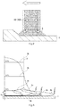
- Fig. 3 shows potential distribution within a jet flow and current density distribution on the workpiece surface, for the electrolytic solution 3 that has been jetted out from a cylindrical nozzle acting as a tool electrode. With electrochemical machining current density at opposing portions of the tool electrode and the workpiece is high, and current density is lowered moving away from that area.
- Reference numeral 3a in Fig. 3 schematically represents current density distribution of the electrolytic solution 3 that exists between the workpiece 1 and the tool electrode 20 (omitted from within Fig. 3 ).
- reference numerals 3b in Fig. 3 schematically represent equipotential surfaces, and here reference numeral V 0 is power source voltage applied between the electrodes (in a case where the workpiece side constitutes an anode).
- a machining amount per unit time in the case of low current density is significantly inferior compared to the case of high current density. If scanning speed is raised, sojourn time of the electrolytic solution jet for a single scan (namely the duration for which electrochemical machining using the opposed electrode is carried out) becomes short, and the effect of the low current region becomes small. As a result, it can be considered that surface roughness improves with increase in scanning speed, as disclosed in previously described nonpatent publication 3.
- an electrolytic reaction does not occur if an electrical double layer is not sufficiently formed.
- elution of the workpiece is confined to a high current density portion directly below the tool electrode by turning off pulse current (namely, turning off machining voltage).
- Electrical charge of the electrical double layer is then discharged in an idle period after a pulse has been turned off, and the next pulse is applied. At this time if the idle time is not sufficient electrical charge of the electrical double layer will not be completely discharged, and an electrolytic reaction will occur even in a low current density region.
- machining current short pulses by making machining current short pulses and providing a sufficient idle time it is possible to confine elution of the workpiece to only a high current density region, and even in cases of scanning at low speed it should be possible to obtain a machining surface having a good surface roughness.
- current density so as not to be able to obtain a mirror surface at the time the tool electrode is at rest is provisionally known, it is preferable to set a time for which a workpiece is exposed to that type of low current density region to short pulse width machining current when an electrode has been scanned, so as to be shorter than a time in which machining at that low current density will occur.
- the tool electrode 20 is scanned relatively within an XY plane with respect to the workpiece 1 using the scanning drive section 60. In this way the surface of the workpiece 1 is machined in the scanning direction, and it is possible to improve the surface roughness. It should be noted that with this embodiment a Z direction position of the tool electrode 20 is fixed during machining, and is adjusted as required.
- Pulse width t 1 is made a constant value such a 100 ⁇ s, and grooving is carried out on the workpiece 1 by scanning the tool electrode 20 while varying pulse idle time t 2 and scanning speed.
- Reference numeral T in Fig. 4 shows pulse period at this time.
- the workpiece 1 is made an anode and the direction of current flowing from the workpiece 1 to the tool electrode 20 is made the vertical axis direction in Fig. 4 .
- DC direct current
- SUS304 was used as the workpiece 1.
- maximum height roughness Rz was measured and averaged at four different locations within a machined surface.
- AC in table 1 shows pulse waveform (alternating current waveform) used in practical example 2.
- Practical example 2 is configured so that in period t 3 (refer to Fig. 6 ) a reverse direction voltage is applied, and reverse direction current flows.
- alternating current flowing between electrodes has a forward direction current component (time t 1 ) that flows, with the workpiece 1 as an anode, from the workpiece 1 to the tool electrode 20, and a reverse direction current component (time t 3 ) that flows, with the workpiece as a cathode, from the tool electrode 20 to the workpiece 1.
- pulse width t 1 to make the workpiece 1 an anode was made constant at 100 ⁇ s
- time t 3 to make the workpiece 1 a cathode was varied, and the effect of AC current duty factor and scanning speed on surface roughness was investigated.
- the charge control means 40 preferably controls output from the power source 10 so that a value obtained by integrating forward direction current with respect to application time of that current (t 1 in Fig. 6 ) (forward direction electrical charge) and a value obtained by integrating reverse direction current with respect to application time of that current (t 3 in Fig. 6 ) (reverse direction electrical charge) become substantially equal.
- a value obtained by integrating forward direction current with respect to application time of that current (t 1 in Fig. 6 ) (forward direction electrical charge) and a value obtained by integrating reverse direction current with respect to application time of that current (t 3 in Fig. 6 ) (reverse direction electrical charge) become substantially equal.
- the charge control means 40 preferably sets a peak value for the reverse direction current component lower than a peak value for the forward direction current component. This is because, generally, if current density is low a proportion of current that is used in removing material on the anode is reduced, and to the extent of that reduction a proportion that is used in oxygen generation and oxidation reactions is increased. In this way it is possible to reduce amount of electrolysis of the tool electrode 20 when reverse direction current flows, and to reduce running cost of the device.
- the reverse direction current pulse width In a case where peak value of the reverse direction current component is set lower than the peak value of the forward direction current component, it is preferable to set the reverse direction current pulse width longer than the forward direction current pulse width in order to sufficiently discharge electrical charge that has been charged in to the electrical double layer. In this way it is possible to increase machining speed to the maximum limit in a range that does not cause unnecessary electrolysis at the tool electrode 20.
- discharging electrical charge of the electrical double layer is an objective purpose, and accumulating electrical charge of a reverse polarity in the electrical double layer is not the purpose in the embodiment. It is therefore preferable to set the pulse width to an upper limit value without reverse direction electrical charge exceeding forward direction electrical charge.
- the charge control means 40 may insert a current idle period between the forward direction current component and the reverse direction current component of the alternating current.
- the current idle period is capable of being inserted during period t 1 in Fig. 6 or in period t 3 , and is a period in which voltage or current becomes 0.
- the reverse direction pulse width (period t 3 ) is preferably set to level such that reverse direction electrical charge does not exceed the forward direction electrical charge
- these phenomena have variations depending on the state of the electrode gap.
- the potential distribution in Fig. 3 is as ideal as possible, and in actual fact erosion products exist, and considerable unevenness exists on the surface profile. There is therefore a possibility of the reverse direction electrical charge exceeding the forward direction electrical charge locally. It is therefore possible, for example, to use this current idle period as an adjustment element.
- reverse direction current is applied after forward direction current application, and after the current idle period has been provided, forward direction current is applied as the next cycle.
- Reverse direction pulse width (period t 3 ) at this time is set so that reverse direction electrical charge becomes about, for example, 2/3 of the forward direction electrical charge, and after that the current idle period is provided. In this way, even if local dispersion is considered, the reverse direction electrical charge does not exceed the forward direction electrical charge, and it is possible to avoid reverse charging into the electrical double layer.
- the opposing area of the workpiece 1 and the tool electrode 20 is preferable to fully cover a surface area to be machined of the workpiece 1 over a fine section span by scanning, and it is also preferable to make a distance between the tool electrode and the workpiece, within the range of the opposing area, small enough that there is no significant lack of uniformity due to the curvature of the workpiece.
- the charge control means 40 of the first embodiment can be configured to change control content in order to eliminate electrical charge, in accordance with scanning of the tool electrode 20. For example, by changing control content in order to eliminate electrical charge in accordance with machining conditions such as distance between electrodes, opposed area of the tool electrode and the workpiece, electrolytic solution supply amount etc. it is possible to carry out more appropriate mirror finishing. Also, by using conditions that are contrary to appropriate conditions for mirror finishing, it is possible to form a partially non-mirrored surface.
- the tool electrode 20 is scanned.
- relative speed between the tool electrode 20 and the workpiece 1 is lowered at locations where scanning is turned around and locations where machining direction has been changed.
- scanning speed on the horizontal axis of Fig. 5 and Fig. 7 is changed, in this vicinity it tends to result in nonuniform machining having a rough surface.
- a rod shaped tool electrode 220 is used instead of the nozzle shaped tool electrode 20 (refer to Fig. 9 ).
- One pole of the power source 10 is electrically connected to both ends of the tool electrode 220 by means of two specified fixtures 221.
- the other pole of the power source 10 is electrically connected to the workpiece 1, similarly to the previously described first embodiment.
- the tool electrode 220 of this embodiment is arranged so as to be substantially parallel to the surface of the workpiece 1, and is capable of scanning along the surface of the workpiece 1.
- the electrolytic solution (not illustrated) in the second embodiment is previously filled between the tool electrode 220 and the surface of the workpiece 1 using a suitable electrolytic bath (not illustrated).
- the workpiece 1 is machined in a state of being immersed in electrolytic solution.
- electrolytic solution may also be supplied to the electrode gap using suitable blowing means.
- Being parallel to the workpiece 1 and the tool electrode 220 is preferable, and if the distance between electrodes varies in the vertical direction it becomes difficult to implement uniform electrochemical machining.
- the tool electrode 220 is held and electrically connected at upper and lower parts by fixtures 221, so that it is difficult for vibration and deformation of the tool electrode 220 to happen.
- this is not at all limiting, and the tool electrode 220 may be held by only one of the upper and lower fixtures 221.
- a wire electrode that is used in a so-called wire electric discharge machine as the tool electrode 220.
- a wire electrode in order to achieve compatibility with a wire electric discharge machine, it is possible for a wire electrode to be used in the both machining actions. For example, after performing wire electric discharge machining on the workpiece 1 and then finishing the surface, it is possible to perform further finishing on the finished machined surface after electric discharge machining, with electrochemical machining using the same wire electrode.
- a block shaped tool electrode 320 is used instead of the nozzle shaped tool electrode 20 (refer to Fig. 10 ).
- One pole of the power source 10 (omitted from Fig. 10 ) is electrically connected to the tool electrode 320.
- the other pole of the power source 10 is electrically connected to the workpiece 1, similarly to the previously described first embodiment.
- the tool electrode 320 of this embodiment can be scanned along the surface of the workpiece 1 with the surface of the tool electrode 320 facing the workpiece 1.
- the electrolytic solution of the third embodiment is supplied between the tool electrode 320 and the workpiece 1 by a nozzle 36.
- the third embodiment similarly to the previously described first embodiment, there is the advantage that it is possible to carry out mirror finishing of the workpiece while suppressing scanning speed, by eliminating electrical charge of the electrical double layer using the charge control means 40. Also, by using alternating current it is possible to expect improvements in machining speed of the electrochemical machining.
- An electrochemical machining device comprising:
- An electrochemical machining device comprising:
- An electrochemical machining device comprising:
- An electrochemical machining device comprising:
- An electrochemical machining device comprising; a tool electrode arranged apart from the workpiece, an electrolytic solution that fills the gap between the workpiece and the tool electrode, and a power source for supplying forward direction current pulses and reverse direction current pulses between the workpiece and the tool electrode, wherein in the electrochemical machining device that carries out electrochemical machining by relatively scanning the tool electrode and the workpiece, a ratio (A/B) of forward direction electrical charge (A) that is supplied between the workpiece and the tool electrode by the forward direction current pulses, and reverse direction electrical charge (B) that is supplied between the workpiece and the tool electrode by the reverse direction current pulses, is set so as to become bigger as speed of the scanning becomes faster.
- An electrochemical machining device comprising:
- An electrochemical machining device comprising:
Landscapes
- Engineering & Computer Science (AREA)
- Chemical & Material Sciences (AREA)
- Chemical Kinetics & Catalysis (AREA)
- Electrochemistry (AREA)
- Mechanical Engineering (AREA)
- Manufacturing & Machinery (AREA)
- Electrical Discharge Machining, Electrochemical Machining, And Combined Machining (AREA)
Abstract
Description
- The present invention relates to an electrochemical machining device and electrochemical machining method.
- Electrolyte jet machining (refer to
non-patent publication 1 andpatent publications 1 and 2 below) is known as one type of electrochemical machining. Electrolyte jet machining is a method for selectively machining only directly below jet flow of an electrolyte, by discharging electrolyte from a nozzle and applying a voltage to a gap between the nozzle and a workpiece. In this case, the nozzle acts as a tool electrode. At the time of electrochemical machining, a voltage is applied between electrodes so that a workpiece becomes an anode, and electric current flows via an electrolytic solution. This machining method has the advantage that since the machining principle is electrolytic action, which is a chemical reaction, it is possible to machine a workpiece regardless of hardness as long as it is a conductive material, and affected layers or residual stress, burrs and cracks etc. do not arise. It is also possible to perform maskless machining of an arbitrary shape by scanning a nozzle. - The present inventors have heretofore disclosed obtaining a mirror surface of small surface roughness under high current density, and obtaining complex porous properties under low current density, by controlling current density, using SUS304 as a workpiece material (non-patent publication 2 below). With the machining method disclosed in these publications, surface roughness of a workpiece is deteriorated due to passage of a low current density region as a result of scanning.
- The present inventors have therefore disclosed being able to perform mirror finishing in an arbitrary shape by scanning a nozzle (tool electrode) at high speed and through multiple reciprocations (non-patent
publication 3 below). - However, generally, in the case of machining complex shapes, in order to scan an electrode a plurality of times at high speed considerable device cost and running cost become necessary. Also, in the case of carrying out high speed scanning, a problem arises in that the electrolytic solution flies out due to movement of the electrode.
- It should be noted that non-patent publication 4 below shows attempts to achieve machining precision through the use of electrochemical machining using ultrashort pulse current that utilizes formation of an electrical double layer on an electrode surface.
-
- Non-Patent
Document 1
Kunieda M, Yoshida M, Yoshida H, Akamatsu Y (1993) Influence of Micro Indents Formed by Electro-chemical Jet Machining on Rolling Bearing Fatigue Life. ASME PED 64:693-699. - Non-Patent Document 2
Kawanaka T, Kunieda M (2014) Selective Surface Texturing Using Electrolyte Jet Machining. Procedia of 2nd CIRP Conference on Surface Integrity (CSI) (13): 345-349. - Non-Patent
Document 3
Natsu W, Ikeda T, Kunieda M (2007) Generating Complicated Surface with Electrolyte Jet Machining. Precision Engineering 31: 33-39. - Non-Patent Document 4
Schuster R, Kircher V, Allonfue P, Etrl F (2000) Electrochemical Micromachining. Science 289(5476): 98-101. -
- Patent Publication 1: Japanese patent laid-open
2006-55933 - Patent Publication 2: Japanese patent laid-open
2011-110641 - The present invention has been conceived in view of the above-described situation. A main object of the present invention is to provide technology that can improve roughness of a machined surface while keeping relative scanning speed of a tool electrode with respect to a workpiece low.
- Means for solving the above described problems can be as disclosed in any of the following aspects.
- An electrochemical machining device for machining a surface of a workpiece using electrochemical machining, comprising
a power source, a tool electrode, an electrolytic solution supply section, and charge control means, wherein
the power source applies a voltage, for making current for electrochemical machining flow, between the tool electrode and the workpiece,
the tool electrode is arranged apart from the workpiece, and is capable of being scanned relatively along a surface direction of the workpiece,
the electrolytic solution supply section can supply electrolytic solution for electrochemical machining between the tool electrode and the workpiece, and
the charge control means eliminates electrical charge that has accumulated between the tool electrode and the workpiece as a result of voltage application from the power source. - The electrochemical machining device of
aspect 1, wherein the power source uses pulse current as the current, and
the charge control means eliminates the electrical charge based on duty factor of the pulse current. - The electrochemical machining device of aspect 2, wherein an upper limit of absolute value of pulse width for the pulse current is set short enough to apply mirror finishing to a surface of the workpiece, and current density of the current for electrochemical machining is set high enough for application of the mirror finishing.
- The electrochemical machining device of
aspect 1, wherein the power source uses alternating current as the current, and
the alternating current has a forward direction current component that makes the workpiece an anode and a reverse direction current component that makes the workpiece a cathode, and
the charge control means eliminates the electrical charge by applying the reverse direction current component. - The electrochemical machining device of aspect 4, wherein the charge control means controls the power source so that a value obtained by integrating forward direction current density of the forward direction current component over application time, and a value obtained by integrating reverse current density of the reverse direction current component over application time, become substantially equal.
- The electrochemical machining device of aspect 5, wherein the charge control means sets a peak value for the reverse direction current component lower than a peak value for the forward direction current component.
- The electrochemical machining device of any one of aspects 4-6, wherein the charge control means eliminates the electrical charge by inserting a current idle period between the forward direction current component and the reverse direction current component of the alternating current.
- The electrochemical machining device of any one of aspects 4-7, wherein the tool electrode is made from monocrystalline silicon, titanium alloy, niobium alloy, graphite, or platinum.
- The electrochemical machining device of any one of aspects 1-8, wherein the power source is a constant voltage source or a constant current source.
- The electrochemical machining device of any one of aspects 1-9, wherein at least part of a surface of the workpiece has a curvature that is not 0, and opposing area of the workpiece and the tool electrode is made small enough, within a range of the opposing area, to be able to regard distribution of distance between the tool electrode and the workpiece as substantially constant regardless of the curvature.
- The electrochemical machining device of any one of aspects 1-10, wherein the charge control means changes content of control for eliminating the electrical charge in accordance with relative scanning of the tool electrode.
- An electrochemical machining method that uses the electrochemical machining device of any one of aspects 1-11 comprising
a step of making a current for electrochemical machining flow between the tool electrode and the workpiece using the power source,
a step of scanning the tool electrode relatively along the surface direction of the workpiece,
a step of supplying electrolytic solution between the tool electrode and the workpiece using the electrolytic solution supply section, and
a step of eliminating electrical charge that has accumulated between the tool electrode and the workpiece using the charge control means. - A surface roughness adjustment method that uses the electrochemical machining device of any one of aspects 1-11 comprising
a step of making a current for electrochemical machining flow between the tool electrode and the workpiece using the power source,
a step of scanning the tool electrode relatively along the surface direction of the workpiece,
a step of supplying electrolytic solution between the tool electrode and the workpiece using the electrolytic solution supply section, and
a step of adjusting surface roughness of the workpiece surface by controlling electrical charge that has accumulated between the tool electrode and the workpiece using the charge control means - An electrochemical machining device, comprising a tool electrode arranged apart from the workpiece,
an electrolytic solution that is filled between the workpiece and the tool electrode, and
a power source for supplying forward direction current pulses and reverse direction current pulses between the workpiece and the tool electrode, wherein
in the electrochemical machining device that carries out electrochemical machining by relatively scanning the tool electrode workpiece and the workpiece,
peak value of the reverse direction current pulses is made lower than peak value of the forward direction current pulses, and pulse width of the reverse direction current pulses is set wider than pulse width of the forward direction current pulses. - An electrochemical machining device, comprising a tool electrode arranged apart from the workpiece,
an electrolytic solution that fills the gap between the workpiece and the tool electrode, and
a power source for supplying forward direction current pulses and reverse direction current pulses between the workpiece and the tool electrode, wherein
in the electrochemical machining device that carries out electrochemical machining by relatively scanning the tool electrode workpiece and the workpiece,
peak value of the reverse direction current pulses is made higher than peak value of the forward direction current pulses, and
pulse width of the reverse direction current pulses is set narrower than pulse width of the forward direction current pulses. - An electrochemical machining device, comprising a tool electrode arranged apart from the workpiece,
an electrolytic solution that fills the gap between the workpiece and the tool electrode, and
a power source for supplying forward direction current pulses and reverse direction current pulses between the workpiece and the tool electrode, wherein
in the electrochemical machining device that carries out electrochemical machining by relatively scanning the tool electrode workpiece and the workpiece,
pulse width of the reverse direction current pulses is set to less than or equal to pulse width of the forward direction current pulses, and
when switching from the reverse direction current pulses to the forward direction current pulses an idle period is provided. - An electrochemical machining device, comprising a tool electrode arranged apart from the workpiece,
an electrolytic solution that fills the gap between the workpiece and the tool electrode, and
a power source for supplying forward direction current pulses and reverse direction current pulses between the workpiece and the tool electrode, wherein
in the electrochemical machining device that carries out electrochemical machining by relatively scanning the tool electrode workpiece and the workpiece,
with respect to forward direction electrical charge that is supplied between the workpiece and the tool electrode by the forward direction current pulses,
reverse direction electrical charge that is supplied between the workpiece and the tool electrode by the reverse direction current pulses is set so as to become small, and
when switching from the reverse direction current pulses to the forward direction current pulses an idle period is provided. - An electrochemical machining device, comprising a tool electrode arranged apart from the workpiece,
an electrolytic solution that fills the gap between the workpiece and the tool electrode, and
a power source for supplying forward direction current pulses and reverse direction current pulses between the workpiece and the tool electrode, wherein
in the electrochemical machining device that carries out electrochemical machining by relatively scanning the tool electrode workpiece and the workpiece,
a ratio (A/B) of forward direction electrical charge (A) that is supplied between the workpiece and the tool electrode by the forward direction current pulses, and reverse direction electrical charge (B) that is supplied between the workpiece and the tool electrode by the reverse direction current pulses, is set so as to become larger as speed of the scanning becomes faster. - An electrochemical machining device, comprising a tool electrode arranged apart from the workpiece,
an electrolytic solution that fills the gap between the workpiece and the tool electrode, and
a power source for supplying forward direction current pulses between the workpiece and the tool electrode, wherein
in the electrochemical machining device that carries out electrochemical machining by relatively scanning the tool electrode workpiece and the workpiece,
a duty factor for applying the forward direction current pulses is set so as to become larger as speed of the scanning becomes faster. - An electrochemical machining device, comprising a tool electrode arranged apart from the workpiece,
an electrolytic solution that fills the gap between the workpiece and the tool electrode, and
a power source for supplying forward direction current pulses and reverse direction current pulses between the workpiece and the tool electrode, wherein
in the electrochemical machining device that carries out electrochemical machining by relatively scanning the tool electrode workpiece and the workpiece,
pulse width of the reverse direction current pulses is set so as to become smaller, with respect to pulse width of the forward direction current pulses, as speed of the scanning becomes faster. - According to the present invention, it is possible to improve roughness of a machined surface, while keeping relative scanning speed of a tool electrode, with respect to a workpiece, low.
-
-
Fig. 1 is an explanatory drawing for explaining the overall structure of an electrochemical machining device of a first embodiment of the present invention. -
Fig. 2 is an expanded cross-sectional view of essential parts ofFig. 1 . -
Fig. 3 is a schematic explanatory drawing for describing the machining principle of electrochemical machining used in the machining device ofFig. 1 . -
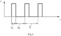
Fig. 4 is an explanatory drawing showing a pulse current waveform used in practical example 1, with the vertical axis being current [A] and the horizontal axis being time [s]. -
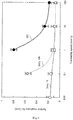
Fig. 5 is a graph showing experimental results of practical example 1, with the vertical axis being surface roughness Rz [µm] and the horizontal axis being translation speed [mm/s]. -
Fig. 6 is an explanatory drawing showing a pulse current waveform (AC waveform) used in practical example 2, with the vertical axis being current [A] and the horizontal axis being time [s]. -
Fig. 7 is a graph showing experimental results of practical example 2, with the vertical axis being surface roughness Rz [µm] and the horizontal axis being translation speed [mm/s]. -
Fig. 8 is an explanatory drawing showing another pulse current waveform (AC waveform) that can be used in practical example 2, with the vertical axis being current [A] and the horizontal axis being time [s]. -
Fig. 9 is an explanatory drawing for describing the schematic structure of an electrochemical machining device of a second embodiment of the present invention. -
Fig. 10 is an explanatory drawing for describing the schematic structure of an electrochemical machining device of a third embodiment of the present invention. - In the following, an electrochemical machining device (hereafter sometimes referred to as "machining device") of a first embodiment of the present invention will be described with reference to the attached drawings . The machining device of this embodiment is for machining a workpiece 1 (refer to
Fig. 1 ) from a surface side thereof using so-called electrolyte jet machining, and in particular is a preferred device in finish machining of a workpiece surface. - The machining device of this embodiment comprises a
power source 10,tool electrode 20, an electrolyticsolution supply section 30 and charge control means 40 as basic elements (refer toFig. 1 ). This machining device is additionally provided with aworkpiece support section 50 and ascanning drive section 60. - The
power source 10 applies a voltage, for making current for electrochemical machining flow, between thetool electrode 20 and aworkpiece 1. In more detail, one electrode of thepower source 10 is electrically connected to thetool electrode 20, another electrode of thepower source 10 is electrically connected to theworkpiece 1, and it is possible to apply a given voltage between the two. - The
power source 10 of this embodiment uses a pulse waveform voltage (pulse voltage) as a voltage to be applied, and in this way it is possible to make current having a pulse waveform (refer to practical example 1 and 2 which will be described later) flow between electrodes. It should be noted that with this embodiment, as thepower source 10, a constant current source that makes a current value that has been designated by the charge control means 40 flow between electrodes is used, but a constant voltage source may also be used as long as the necessary current value can be obtained. It is also possible to use a so-called high-speed bipolar power source, for example, as thepower source 10 of this embodiment. - In the
power source 10 of this embodiment, an upper limit of absolute value for pulse width of the pulse current is set small enough that mirror finishing can be applied to a surface of theworkpiece 1. Also, a lower limit for current density is set to a value at which machining marks are finished to a mirror surface while the tool electrode is at rest. What level of current density and pulse width should be set to make it possible to accomplish mirror finishing can be determined by experimentation, for example. Here, current density is obtained by dividing electrical current by an opposing area of the tool electrode and the workpiece. Also, the mirror finishing is machining that makes surface roughness small, for example, machining to make surface roughness Rz 0.3µm or less. An upper limit for the absolute value of pulse width is, for example, 150 µs to 100 µs. However, the present invention is not limited to these numerical values. - The
tool electrode 20 is arranged apart from theworkpiece 1, and is capable of being scanned relatively along a surface direction of theworkpiece 1. Specifically, thetool electrode 20 of this example is provided with abase portion 21 and atip portion 22. - The
base portion 21 is formed in a hollow cylindrical shape, and connected to piping 32 (described later) of the electrolyticsolution supply section 30 which is constructed so as to feed electrolytic solution to thetip portion 22. - The
tip portion 22 extends from a tip side of thebase portion 21 in the direction of the workpiece 1 (downward direction inFig. 1 ). Thetip portion 22 is also formed in a hollow cylindrical shape, so as to be able to discharge a jet of electrolytic solution 3 (described later) to the workpiece 1 (refer toFig. 2 ). It should be noted that inFig. 2 only portions of thetip portion 22 are shown enlarged. Also, the flow state of theelectrolytic solution 3 inFig. 2 is only shown schematically and is not an accurate depiction. Thetool electrode 20 of this embodiment has the function of a nozzle for so-called electrolyte jet machining. - As material for the
tool electrode 20, various materials can be used as long as it is conductive, and has the necessary mechanical strength. In particular, in a case where monocrystalline silicon, titanium alloy, niobium alloy, graphite or platinum has been used as the material for thetool electrode 20, these materials are suitable since they are difficult to electrolyze even if a reverse direction voltage (voltage that makes the workpiece a cathode) is applied. - Here, in a case where at least part of the surface of the
workpiece 1 has a curvature that is not 0, an opposing area of theworkpiece 1 and thetool electrode 20 is preferably "sufficiently small that distance between thetool electrode 20 and theworkpiece 1 within this opposing area is effectively uniform regardless of the curvature". If this is done it is possible to apply appropriate mirror finishing even to a workpiece having a non-flat surface to be machined, by scanning the machined surface. Making the distance between theworkpiece 1 and thetool electrode 20 constant, and sufficiently narrow (for example, making a gap of 1mm or less, more preferably 0.5mm or less) is preferable for the realization of mirror finishing. Accordingly, using atool electrode 20 that has a small opposing area like this contributes to satisfying these gap conditions. - The electrolytic
solution supply section 30 can supply electrolytic solution for electrochemical machining between thetip portion 22 of thetool electrode 20 and the surface to be machined of the workpiece 1 (upper surface inFig. 1 ). In more detail, the electrolyticsolution supply section 30 of this embodiment is provided with atank 31, piping 32, apump 33 and asink 34. - The
tank 31 is a section for accumulatingelectrolytic solution 3 for electrochemical machining. Here, it is possible to use various fluids that are normally used for electrochemical machining as theelectrolytic solution 3. - The piping 32 connects between the
tank 31 and thebase portion 21 of thetool electrode 20. Thepump 33 is attached at some point along the piping 32, and can feedelectrolytic solution 3 to thetool electrode 20 in an appropriate flow amount. With this embodiment, in order to obtain an accurate flow amount a so-called gear pump has been used as thepump 33, but this is not restrictive. - The
sink 34 is a section that temporarily holds electrolytic solution that has been supplied towards theworkpiece 1. Adrain section 341 for dischargingelectrolytic solution 3 that has been supplied is formed in thesink 34.Electrolytic solution 3 that has been discharged from thesink 34 is recovered using an appropriate method that is not illustrated. - The charge control means 40 is a functional element for eliminating electrical charge that has accumulated between the
tool electrode 20 and theworkpiece 1 as a result of voltage application from thepower source 10. More specifically, the charge control means 40 of this embodiment is implemented as a controller (for example, a function generator) for adjusting a current waveform (for example, current pulse width, peak value, pulse frequency etc.) attributable to voltage from thepower source 10. As an actual device structure, the charge control means 40 may be part of the functions within thepower source 10. Basically, the charge control means is not restricted to a mechanical structure as long as it is capable of exhibiting the necessary functions, and can also be implemented, for example, using a combination of a computer and computer programs, and does not need to exist as a single element. - The charge control means 40 of this embodiment is configured to eliminate electrical charge that has accumulated between the electrodes based on a duty factor of pulse current. Detailed operation of the charge control means 40 (specifically a current waveform) will be described later using practical example 1 and 2.
- The
workpiece support section 50 is for supporting theworkpiece 1 which constitutes the object of electrochemical machining, and with this embodiment is constructed using a machining table. - The
scanning drive section 60 comprises an XZdirection drive section 61 and a Ydirection drive section 62 with this embodiment. The XZdirection drive section 61 can move thetool electrode 20 at a given speed in an X direction (left to right direction inFig. 1 ), and in a Z direction (up and down direction inFig. 1 ). The Ydirection drive section 62 can move theworkpiece support section 50 at a given speed in a Y direction (a direction perpendicular to the sheet ofFig. 1 ), via thesink 34. Control of operations such as scanning speed and scanning direction of thescanning drive section 60 can be implemented by a controller, not illustrated. Using thescanning drive section 60, with this embodiment it is possible to scan thetool electrode 20 relative to theworkpiece 1 in an arbitrary direction within an XY plane. - Operation of the machining device of the previously described first embodiment will be described in the following.
- As a prerequisite for operation description, the machining principle of the electrochemical machining of this embodiment will be described with further reference to
Fig. 3 . -
Fig. 3 shows potential distribution within a jet flow and current density distribution on the workpiece surface, for theelectrolytic solution 3 that has been jetted out from a cylindrical nozzle acting as a tool electrode. With electrochemical machining current density at opposing portions of the tool electrode and the workpiece is high, and current density is lowered moving away from that area.Reference numeral 3a inFig. 3 schematically represents current density distribution of theelectrolytic solution 3 that exists between theworkpiece 1 and the tool electrode 20 (omitted from withinFig. 3 ). Also,reference numerals 3b inFig. 3 schematically represent equipotential surfaces, and here reference numeral V0 is power source voltage applied between the electrodes (in a case where the workpiece side constitutes an anode). - With machining that scans a tool electrode (scanning machining), when directly beneath a nozzle of high current density passes a point on the workpiece, if that current density is sufficiently high that a mirror surface can be obtained when the nozzle is at rest, the workpiece surface directly beneath the nozzle is machined to a mirror surface. However, after that a peripheral section thereof with low current density passes through that machining portion. In a case where scanning speed is slow, the workpiece surface is roughened by electrochemical machining due to the peripheral section with low current density, and surface roughness becomes large (that is, from the perspective aimed at mirror finishing, the mirror surface is degraded).
- However, a machining amount per unit time in the case of low current density is significantly inferior compared to the case of high current density. If scanning speed is raised, sojourn time of the electrolytic solution jet for a single scan (namely the duration for which electrochemical machining using the opposed electrode is carried out) becomes short, and the effect of the low current region becomes small. As a result, it can be considered that surface roughness improves with increase in scanning speed, as disclosed in previously described
nonpatent publication 3. - On the other hand, in recent years, for the purpose of improving machining precision, electrochemical machining has been carried out using ultrashort pulse current that utilizes formation of an electrical double layer on an electrode surface (previously described non-patent publication 4). If a voltage is applied between the
workpiece 1 and thetool electrode 20, an electrical double layer having a form that confronts positive and negative electrical charge is formed on the workpiece surface, as shown inFig. 3 . The phenomenon forming this electrical double layer can be realized by charging of electrical charge into a capacitor CDL and because of differences in current density a difference in charge time of the electrical double layer arises. It should be noted that reference numeral R in the drawing represents a resistive component within the electrolytic solution jet. - According to the findings of the present inventors, an electrolytic reaction does not occur if an electrical double layer is not sufficiently formed. Before an electrical double layer is formed at a low current density portion, elution of the workpiece is confined to a high current density portion directly below the tool electrode by turning off pulse current (namely, turning off machining voltage). Electrical charge of the electrical double layer is then discharged in an idle period after a pulse has been turned off, and the next pulse is applied. At this time if the idle time is not sufficient electrical charge of the electrical double layer will not be completely discharged, and an electrolytic reaction will occur even in a low current density region. Accordingly, by making machining current short pulses and providing a sufficient idle time it is possible to confine elution of the workpiece to only a high current density region, and even in cases of scanning at low speed it should be possible to obtain a machining surface having a good surface roughness. To give further information, if current density so as not to be able to obtain a mirror surface at the time the tool electrode is at rest is provisionally known, it is preferable to set a time for which a workpiece is exposed to that type of low current density region to short pulse width machining current when an electrode has been scanned, so as to be shorter than a time in which machining at that low current density will occur.
- The above is the machining principle that is the prerequisite for this embodiment, based on the findings of the present inventors.
- In the case of carrying out electrochemical machining using the machining device of this embodiment, first of all the
workpiece 1 is arranged on an upper surface of the workpiece support section 50 (refer toFig. 1 ). Thenelectrolytic solution 3 is supplied between thetool electrode 20 and theworkpiece 1 by the electrolyticsolution supply section 30. At this time, theelectrolytic solution 3 passes through thetip portion 22 of thetool electrode 20 and is supplied to machining locations (refer toFig. 2 ). On the other hand a voltage is applied at a given waveform between thetool electrode 20 and theworkpiece 1, by thepower source 10. In this way it is possible to make current for specified electrochemical machining flow between the two. Here, a waveform of electrical current that flows between thetool electrode 20 and theworkpiece 1 is set by the charge control means 40 (refer to practical example 1 and 2 that will be described later). - Further, with this embodiment the
tool electrode 20 is scanned relatively within an XY plane with respect to theworkpiece 1 using thescanning drive section 60. In this way the surface of theworkpiece 1 is machined in the scanning direction, and it is possible to improve the surface roughness. It should be noted that with this embodiment a Z direction position of thetool electrode 20 is fixed during machining, and is adjusted as required. - In the following, the electrochemical machining operation of this example will be described in more detail with reference to a specific practical example.
- Based on the previously described machining principle, electrochemical machining is carried out for conditions (Pulse) in table 1 below, using the device structure of the first embodiment.
Table 1 Table 1 Machining conditions Pulse AC Pulse on time [µs] 100 100 Duty factor [%] 1, 10 59, 67, 77 Machining current [A] ± 3.0 Current density [A/cm2] 187 Gap width [mm] 0.5 Flow rate [ml/s] 5.2 Nozzle inner diameter [mm] 1.43 Electrolyte NaNO3aq 20wt% - The meaning of items shown in this table is as shown below. It should be noted that for reference one example of a current waveform based on pulse voltage applied from the power source is shown in
Fig. 4 . Also, in table 1, conditions (AC) for a case where an alternating waveform is applied are also depicted, but the alternating case will be described later. -
- Pulse on time [µs] : Machining current application time (t1 in
Fig. 4 ) ; - Duty factor [%]: Duty factor (t1/T in
Fig. 4 ); - Machining current [A]: current flowing between electrodes;
- Current density [A/cm2]: current density between electrodes;
- Gap width [mm]: distance between the tool electrode and the workpiece;
- Flow rate [ml/s]: flow rate of electrolytic solution;
- Nozzle inner diameter [mm]: inner diameter of nozzle of tip portion of tool electrode;
- Electrolyte : electrolytic solution.
- Current density between the electrodes is not uniform, but in the previous description a value obtained by dividing machining current value by internal area of the nozzle vent was made current density, for the sake of simplicity. As will be understood, the descriptions in table 1 are merely one example, and other appropriate structures are possible.
- With practical example 1, pulse current is used. Pulse width t1 is made a constant value such a 100µs, and grooving is carried out on the
workpiece 1 by scanning thetool electrode 20 while varying pulse idle time t2 and scanning speed. Reference numeral T inFig. 4 shows pulse period at this time. Theworkpiece 1 is made an anode and the direction of current flowing from theworkpiece 1 to thetool electrode 20 is made the vertical axis direction inFig. 4 . Also, for the purpose of comparison, the same machining was also carried out with direct current (DC), namely under conditions of t2=0, duty factor=100%. In this way the effect of pulse current duty factor and scanning speed on the surface roughness was looked into. SUS304 was used as theworkpiece 1. With regard to surface roughness of theworkpiece 1, maximum height roughness Rz was measured and averaged at four different locations within a machined surface. - Measurement results for surface roughness when the scanning speed was varied are shown in
Fig. 5 . The curved lines indicated as "Duty" inFig. 5 show the result data at a given duty factor (%) . As shown inFig. 5 , in a case where pulse current is used, and in a case where DC is used, it will be understood that surface roughness is lowered by raising scanning speed. On the other hand, when scanning speed is slow, with a pulse width of 100µs, surface roughness improves with increase in length of idle period (that is, lowering of duty factor). In this way, in a case where sufficient voltage idle time has been set for a constant value such as pulse width 100µs (that is,duty factor 1%), it will be understood that even in the case of low speed scanning, a mirror surface of good surface roughness can be obtained. It can be assumed that this is because, as was discussed above, in electrolyte jet machining (namely electrochemical machining where an electrode is scanned in an arbitrary direction) also, a machining region is confined to only a high current density region. - Accordingly, according to practical example 1 it is possible to eliminate electrical charge between electrodes using the charge control means 40, and in this way it will be understood that it is possible to improve surface roughness of the machined surface while keeping scanning speed low. It is also possible to control surface roughness of the machined surface by adjusting duty factor using the charge control means 40.
- After changing the voltage waveform to be applied (namely current waveform flowing between electrodes) to that shown in
Fig. 6 , electrochemical machining is carried out under the same conditions as for practical example 1. AC in table 1 shows pulse waveform (alternating current waveform) used in practical example 2. Practical example 2 is configured so that in period t3 (refer toFig. 6 ) a reverse direction voltage is applied, and reverse direction current flows. In this way, alternating current flowing between electrodes has a forward direction current component (time t1) that flows, with theworkpiece 1 as an anode, from theworkpiece 1 to thetool electrode 20, and a reverse direction current component (time t3) that flows, with the workpiece as a cathode, from thetool electrode 20 to theworkpiece 1. - In a case where unipolar pulse current is used, such as practical example 1, in order to obtain a mirror surface with low speed scanning it is necessary to lengthen idle time (refer to
Fig. 5 ). However, if duty factor is lowered removal amount per unit time is low compared to the case of using direct current, which tends to increase machining time. - With practical example 2, by using alternating current, as described previously, polarity of current flowing between the electrodes is reversed and a time t3 where the workpiece becomes a cathode exists. During this t3, it is possible to forcibly discharge electrical charge that has been charged into an electrical double layer (refer to capacitor CDL in
Fig. 3 ). That is, the charge control means 40 of practical example 2 is configured to eliminate electrical charge that has been charged into the electrical double layer using application of the reverse direction current component. It should be noted that in this specification "eliminate electrical charge" means so-called discharging of electrical charge, and means not only the complete elimination of electrical charge but also reduction in the amount of electrical charge that has been accumulated. - In this speculation, it can be considered that mirror finishing will become possible, without setting a long idle time, by using an alternating current waveform. With this practical example 2, therefore, pulse width t1 to make the
workpiece 1 an anode was made constant at 100µs, time t3 to make the workpiece 1 a cathode, and scanning speed, were varied, and the effect of AC current duty factor and scanning speed on surface roughness was investigated. - Experimental results for practical example 2 are shown in
Fig. 7 . As shown inFig. 7 , in a case where AC current is used also, similarly to when direct current and unipolar pulse current is used, (refer toFig. 5 ), it will be understood that surface roughness is lowered together with raising of scanning speed. Also, when scanning speed is slow, with a pulse width of 100µs, it is possible to improve surface roughness with increase in polarity inversion time t3 (that is, lowering of duty factor). On the other hand, in a case where alternating current is used in low speed scanning machining, then compared to the case of using unipolar pulse current in practical example 1, it will be understood that a machined surface having good surface roughness can be obtained while duty factor is high. Specifically, by applying a reverse direction current component using the charge control means 40, an improvement in the machining speed of mirror finishing can be expected. - It should be noted that with practical example 2 a rectangular wave has been used for the alternating current, but it is also possible to use a different waveform, such as a triangular wave or a sine wave (
Fig. 8 ). - Also, with this practical example, the charge control means 40 preferably controls output from the
power source 10 so that a value obtained by integrating forward direction current with respect to application time of that current (t1 inFig. 6 ) (forward direction electrical charge) and a value obtained by integrating reverse direction current with respect to application time of that current (t3 inFig. 6 ) (reverse direction electrical charge) become substantially equal. By doing this, then since it is possible to almost completely discharge electrical charge that has been charged into the electrical double layer (refer to capacitor CDL inFig. 3 ), if the duty factor is the same it is possible to obtain better surface roughness. - Further, with this practical example the charge control means 40 preferably sets a peak value for the reverse direction current component lower than a peak value for the forward direction current component. This is because, generally, if current density is low a proportion of current that is used in removing material on the anode is reduced, and to the extent of that reduction a proportion that is used in oxygen generation and oxidation reactions is increased. In this way it is possible to reduce amount of electrolysis of the
tool electrode 20 when reverse direction current flows, and to reduce running cost of the device. - In a case where peak value of the reverse direction current component is set lower than the peak value of the forward direction current component, it is preferable to set the reverse direction current pulse width longer than the forward direction current pulse width in order to sufficiently discharge electrical charge that has been charged in to the electrical double layer. In this way it is possible to increase machining speed to the maximum limit in a range that does not cause unnecessary electrolysis at the
tool electrode 20. Obviously, as has been described above, discharging electrical charge of the electrical double layer is an objective purpose, and accumulating electrical charge of a reverse polarity in the electrical double layer is not the purpose in the embodiment. It is therefore preferable to set the pulse width to an upper limit value without reverse direction electrical charge exceeding forward direction electrical charge. - With this practical example, the charge control means 40 may insert a current idle period between the forward direction current component and the reverse direction current component of the alternating current. The current idle period is capable of being inserted during period t1 in
Fig. 6 or in period t3, and is a period in which voltage or current becomes 0. - While the reverse direction pulse width (period t3) is preferably set to level such that reverse direction electrical charge does not exceed the forward direction electrical charge, these phenomena have variations depending on the state of the electrode gap. For example, the potential distribution in
Fig. 3 is as ideal as possible, and in actual fact erosion products exist, and considerable unevenness exists on the surface profile. There is therefore a possibility of the reverse direction electrical charge exceeding the forward direction electrical charge locally. It is therefore possible, for example, to use this current idle period as an adjustment element. - Specifically, reverse direction current is applied after forward direction current application, and after the current idle period has been provided, forward direction current is applied as the next cycle. Reverse direction pulse width (period t3) at this time is set so that reverse direction electrical charge becomes about, for example, 2/3 of the forward direction electrical charge, and after that the current idle period is provided. In this way, even if local dispersion is considered, the reverse direction electrical charge does not exceed the forward direction electrical charge, and it is possible to avoid reverse charging into the electrical double layer. Also, compared to practical example 1 where only a simple current idle period was inserted, in a case where means for applying reverse direction current is adopted, since it is possible to eliminate electrical charge of the electrical double layer at high-speed, it is possible to carry out electrochemical machining at high speed while acquiring a mirror surface.
- While it is desirable to have a low current peak value since reverse direction current depletes an electrode, it is possible to alleviate or eliminate a problem such as electrode electrolysis as long as reverse direction pulse width is sufficiently short even with reverse direction current peak value being set high. Since it is possible to eliminate electrical charge that has been accumulated in the electrical double layer at an early stage by setting peak value of the reverse direction current component higher than peak value of the forward direction current component, it is possible for the reverse direction pulse width (period t3) to be set short. Specifically, since it is possible to increase duty factor while preventing electrode consumption, it is possible to improve machining speed. It is obviously also possible to set current idle period after applying a reverse direction current pulses, as described above.
- In the first embodiment described above, the opposing area of the
workpiece 1 and thetool electrode 20 is preferable to fully cover a surface area to be machined of theworkpiece 1 over a fine section span by scanning, and it is also preferable to make a distance between the tool electrode and the workpiece, within the range of the opposing area, small enough that there is no significant lack of uniformity due to the curvature of the workpiece. - Also, the charge control means 40 of the first embodiment can be configured to change control content in order to eliminate electrical charge, in accordance with scanning of the
tool electrode 20. For example, by changing control content in order to eliminate electrical charge in accordance with machining conditions such as distance between electrodes, opposed area of the tool electrode and the workpiece, electrolytic solution supply amount etc. it is possible to carry out more appropriate mirror finishing. Also, by using conditions that are contrary to appropriate conditions for mirror finishing, it is possible to form a partially non-mirrored surface. - With this embodiment, the
tool electrode 20 is scanned. In a case where reciprocating motion is repeated and machining direction is changed, relative speed between thetool electrode 20 and theworkpiece 1 is lowered at locations where scanning is turned around and locations where machining direction has been changed. Specifically, since scanning speed on the horizontal axis ofFig. 5 andFig. 7 is changed, in this vicinity it tends to result in nonuniform machining having a rough surface. With the intention of preventing this, it is possible to change duty factor, reverse polarity pulse width and reverse polarity current value in accordance with scanning speed. For example, it is possible to obtain a uniform surface roughness by operating the charge control means 40, at a returning point of the reciprocating motion, so as to make the idle time long compared to in regions before and after that, or alternatively such that reverse currents pulse width is widened. - Next, an electrochemical machining device of a second embodiment of the present invention will be described with reference to
Fig. 9 . In the description of the second embodiment, for elements that are basically common to the previously described first embodiment complicated description will be avoided by using the same reference numerals. - In the previously described first embodiment so-called electrolyte jet machining was used. Conversely, with the second embodiment a jet is not used and normal electrochemical machining is assumed.
- With the machining device of the second embodiment, a rod shaped
tool electrode 220 is used instead of the nozzle shaped tool electrode 20 (refer toFig. 9 ). One pole of thepower source 10 is electrically connected to both ends of thetool electrode 220 by means of two specifiedfixtures 221. The other pole of thepower source 10 is electrically connected to theworkpiece 1, similarly to the previously described first embodiment. - The
tool electrode 220 of this embodiment is arranged so as to be substantially parallel to the surface of theworkpiece 1, and is capable of scanning along the surface of theworkpiece 1. The electrolytic solution (not illustrated) in the second embodiment is previously filled between thetool electrode 220 and the surface of theworkpiece 1 using a suitable electrolytic bath (not illustrated). - Specifically, the
workpiece 1 is machined in a state of being immersed in electrolytic solution. Obviously, since it is assumed that erosion products will arise between theworkpiece 1 and thetool electrode 220, electrolytic solution may also be supplied to the electrode gap using suitable blowing means. Being parallel to theworkpiece 1 and thetool electrode 220 is preferable, and if the distance between electrodes varies in the vertical direction it becomes difficult to implement uniform electrochemical machining. For this reason thetool electrode 220 is held and electrically connected at upper and lower parts byfixtures 221, so that it is difficult for vibration and deformation of thetool electrode 220 to happen. However, this is not at all limiting, and thetool electrode 220 may be held by only one of the upper andlower fixtures 221. - Furthermore it is also possible to use a wire electrode that is used in a so-called wire electric discharge machine as the
tool electrode 220. Furthermore, in order to achieve compatibility with a wire electric discharge machine, it is possible for a wire electrode to be used in the both machining actions. For example, after performing wire electric discharge machining on theworkpiece 1 and then finishing the surface, it is possible to perform further finishing on the finished machined surface after electric discharge machining, with electrochemical machining using the same wire electrode. By having a structure with which it is possible to switch between wire electric discharge machining and electrochemical machining within the same device, there is the advantage that work involved in positioning thetool electrode 220 and theworkpiece 1 parallel to each other becomes easy. - With the second embodiment also, similarly to the previously described first embodiment, there is the advantage that it is possible to carry out mirror finishing of the workpiece while suppressing scanning speed, by eliminating electrical charge of the electrical double layer using the charge control means 40. Also, by using alternating current it is possible to expect improvements in machining speed of the electrochemical machining.
- The remaining structure and advantages of second embodiment are the same as those of the previously described first embodiment, and so further description will be omitted.
- Next, an electrochemical machining device of a second embodiment of the present invention will be described with reference to
Fig. 10 . In the description of the third embodiment, for elements that are basically common to the previously described first embodiment complicated description will be avoided by using the same reference numerals. - With the third embodiment, similarly to the previously described second embodiment, a jet is not used and normal electrochemical machining is assumed.
- With the machining device of the third embodiment, a block shaped
tool electrode 320 is used instead of the nozzle shaped tool electrode 20 (refer toFig. 10 ). One pole of the power source 10 (omitted fromFig. 10 ) is electrically connected to thetool electrode 320. The other pole of thepower source 10 is electrically connected to theworkpiece 1, similarly to the previously described first embodiment. - The
tool electrode 320 of this embodiment can be scanned along the surface of theworkpiece 1 with the surface of thetool electrode 320 facing theworkpiece 1. The electrolytic solution of the third embodiment is supplied between thetool electrode 320 and theworkpiece 1 by anozzle 36. - With the third embodiment also, similarly to the previously described first embodiment, there is the advantage that it is possible to carry out mirror finishing of the workpiece while suppressing scanning speed, by eliminating electrical charge of the electrical double layer using the charge control means 40. Also, by using alternating current it is possible to expect improvements in machining speed of the electrochemical machining.
- The remaining structure and advantages of third embodiment are the same as those of the previously described first embodiment, and so further description will be omitted.
- It should be noted that the present invention is not limited to the previously described embodiments, and various modifications can be additionally obtained within a scope that does not depart from the gist of the present invention.
- The invention described in each of the previously described embodiments can be considered to be described in the following aspects.
- An electrochemical machining device, comprising:
- a tool electrode arranged apart from the workpiece,
- an electrolytic solution that is filled between the workpiece and the tool electrode, and
- a power source for supplying forward direction current pulses and reverse direction current pulses between the workpiece and the tool electrode, wherein
- in the electrochemical machining device that carries out electrochemical machining by relatively scanning the tool electrode and the workpiece,
- peak value of the reverse direction current pulses is made lower than peak value of the forward direction current pulses, and pulse width of the reverse direction current pulses is set wider than pulse width of the forward direction current pulses.
- An electrochemical machining device, comprising:
- a tool electrode arranged apart from the workpiece,
- an electrolytic solution that fills the gap between the workpiece and the tool electrode, and
- a power source for supplying forward direction current pulses and reverse direction current pulses between the workpiece and the tool electrode, wherein
- in the electrochemical machining device that carries out electrochemical machining by relatively scanning the tool electrode and the workpiece,
- peak value of the reverse direction current pulses is made higher than peak value of the forward direction current pulses, and
- pulse width of the reverse direction current pulses is set narrower than pulse width of the forward direction current pulses.
- An electrochemical machining device, comprising:
- a tool electrode arranged apart from the workpiece,
- an electrolytic solution that fills the gap between the workpiece and the tool electrode, and
- a power source for supplying forward direction current pulses and reverse direction current pulses between the workpiece and the tool electrode, wherein
- in the electrochemical machining device that carries out electrochemical machining by relatively scanning the tool electrode and the workpiece,
- pulse width of the reverse direction current pulses is set to less than or equal to pulse width of the forward direction current pulses, and
- when switching from the reverse direction current pulses to the forward direction current pulses an idle period is provided.
- An electrochemical machining device, comprising:
- a tool electrode arranged apart from the workpiece,
- an electrolytic solution that fills the gap between the workpiece and the tool electrode, and
- a power source for supplying forward direction current pulses and reverse direction current pulses between the workpiece and the tool electrode, wherein
- in the electrochemical machining device that carries out electrochemical machining by relatively scanning the tool electrode and the workpiece,
- with respect to forward direction electrical charge that is supplied between the workpiece and the tool electrode by the forward direction current pulses, reverse direction electrical charge that is supplied between the workpiece and the tool electrode by the reverse direction current pulses is set so as to become small, and
- when switching from the reverse direction current pulses to the forward direction current pulses an idle period is provided.
- An electrochemical machining device, comprising;
a tool electrode arranged apart from the workpiece,
an electrolytic solution that fills the gap between the workpiece and the tool electrode, and
a power source for supplying forward direction current pulses and reverse direction current pulses between the workpiece and the tool electrode, wherein
in the electrochemical machining device that carries out electrochemical machining by relatively scanning the tool electrode and the workpiece,
a ratio (A/B) of forward direction electrical charge (A) that is supplied between the workpiece and the tool electrode by the forward direction current pulses, and reverse direction electrical charge (B) that is supplied between the workpiece and the tool electrode by the reverse direction current pulses, is set so as to become bigger as speed of the scanning becomes faster. - An electrochemical machining device, comprising:
- a tool electrode arranged apart from the workpiece,
- an electrolytic solution that fills the gap between the workpiece and the tool electrode, and
- a power source for supplying forward direction current pulses between the workpiece and the tool electrode, wherein
- in the electrochemical machining device that carries out electrochemical machining by relatively scanning the tool electrode and the workpiece, a duty factor for applying the forward direction current pulses is set so as to become larger as speed of the scanning becomes faster.
- An electrochemical machining device, comprising:
- a tool electrode arranged apart from the workpiece,
- an electrolytic solution that fills the gap between the workpiece and the tool electrode, and
- a power source for supplying forward direction current pulses and reverse direction current pulses between the workpiece and the tool electrode, wherein
- in the electrochemical machining device that carries out electrochemical machining by relatively scanning the tool electrode and the workpiece, pulse width of the reverse direction current pulses is set so as to become smaller, with respect to pulse width of the forward direction current pulses, as speed of the scanning becomes faster.
-
- 1 workpiece
- 3 electrolytic solution
- 10 power source
- 20, 220, 320 tool electrode
- 21 base section
- 22 tip portion
- 221 fixture
- 30 electrolytic solution supply section
- 31 tank
- 32 piping
- 33 pump
- 34 sink
- 341 drain section
- 36 nozzle
- 40 charge control means
- 50 workpiece support section
- 60 scanning drive section
- 61 XZ direction drive section
- 62 Y direction drive section
- t1 pulse width
- t2 pulse idle time
- t3 polarity inversion time
- T pulse cycle
- R resistive component inside electrolytic solution jet
- CDL capacitive component corresponding to electrical double layer
Claims (20)
- An electrochemical machining device for machining a surface of a workpiece using electrochemical machining, comprising
a power supply, a tool electrode, an electrolytic solution supply section, and charge control means, wherein
the power source applies a voltage, for making current for electrochemical machining flow, between the tool electrode and the workpiece,
the tool electrode is arranged apart from the workpiece, and is capable of being scanned relatively along a surface direction of the workpiece,
the electrolytic solution supply section can supply electrolytic solution for electrochemical machining between the tool electrode and the workpiece, and
the charge control means eliminates electrical charge that has accumulated between the tool electrode and the workpiece as a result of voltage application from the power source. - The electrochemical machining device of claim 1, wherein the power source uses pulse current as the current, and
the charge control means eliminates the electrical charge based on duty factor of the pulse current. - The electrochemical machining device of claim 2, wherein an upper limit of absolute value of pulse width for the pulse current is set short enough to apply mirror finishing to a surface of the workpiece, and current density of the current for electrochemical machining is set high enough for application of the mirror finishing.
- The electrochemical machining device of claim 1, wherein
the power source uses alternating current as the current,
the alternating current has a forward direction current component that makes the workpiece an anode and a reverse direction current component that makes the workpiece a cathode, and
the charge control means eliminates the electrical charge by applying the reverse direction current component. - The electrochemical machining device of claim 4, wherein the charge control means controls the power source so that a value obtained by integrating forward direction current density of the forward direction current component over application time, and a value obtained by integrating reverse current density of the reverse direction current component over application time, become substantially equal.
- The electrochemical machining device of claim 5, wherein the charge control means sets a peak value for the reverse direction current component lower than a peak value for the forward direction current component.
- The electrochemical machining device of any one of claims 4-6, wherein the charge control means eliminates the electrical charge by inserting a current idle period between the forward direction current component and the reverse direction current component of the alternating current.
- The electrochemical machining device of any one of claims 4-7, wherein the tool electrode is made from monocrystalline silicon, titanium alloy, niobium alloy, graphite, or platinum.
- The electrochemical machining device of any one of claims 1-8, wherein the power source is a constant voltage source or a constant current source.
- The electrochemical machining device of any one of claims 1-9, wherein at least part of a surface of the workpiece has a curvature that is not 0, and an opposing area of the workpiece and the tool electrode is made sufficiently small that distribution of distance between the tool electrode and the workpiece within a range of this opposing area is regarded as substantially constant regardless of the curvature.
- The electrochemical machining device of any one of claims 1-10, wherein the charge control means changes content of control for eliminating the electrical charge in accordance with relative scanning of the tool electrode.
- An electrochemical machining method that uses the electrochemical machining device of any one of claims 1-11 comprising
a step of making a current for electrochemical machining flow between the tool electrode and the workpiece using the power source,
a step of scanning the tool electrode relatively along the surface direction of the workpiece,
a step of supplying electrolytic solution between the tool electrode and the workpiece using the electrolytic solution supply section, and
a step of eliminating electrical charge that has accumulated between the tool electrode and the workpiece using the charge control means. - A surface roughness adjustment method that uses the electrochemical machining device of any one of claims 1-11, comprising
a step of making a current for electrochemical machining flow between the tool electrode and the workpiece using the power source,
a step of scanning the tool electrode relatively along the surface direction of the workpiece,
a step of supplying electrolytic solution between the tool electrode and the workpiece using the electrolytic solution supply section, and
a step of adjusting surface roughness of the workpiece surface by controlling electrical charge that has accumulated between the tool electrode and the workpiece using the charge control means. - An electrochemical machining device, comprising:a tool electrode arranged apart from the workpiece,an electrolytic solution that fills the gap between the workpiece and the tool electrode, anda power source for supplying forward direction current pulses and reverse direction current pulses between the workpiece and the tool electrode, whereinin the electrochemical machining device that carries out electrochemical machining by relatively scanning the tool electrode and the workpiece,peak value of the reverse direction current pulses is made lower than peak value of the forward direction current pulses, and pulse width of the reverse direction current pulses is set wider than pulse width of the forward direction current pulses.
- An electrochemical machining device, comprising:a tool electrode arranged apart from the workpiece,an electrolytic solution that fills the gap between the workpiece and the tool electrode, anda power source for supplying forward direction current pulses and reverse direction current pulses between the workpiece and the tool electrode, whereinin the electrochemical machining device that carries out electrochemical machining by relatively scanning the tool electrode and the workpiece,peak value of the reverse direction current pulses is made higher than peak value of the forward direction current pulses, andpulse width of the reverse direction current pulses is set narrower than pulse width of the forward direction current pulses.
- An electrochemical machining device, comprising:a tool electrode arranged apart from the workpiece,an electrolytic solution that fills the gap between the workpiece and the tool electrode, anda power source for supplying forward direction current pulses and reverse direction current pulses between the workpiece and the tool electrode, whereinin the electrochemical machining device that carries out electrochemical machining by relatively scanning the tool electrode and the workpiece,pulse width of the reverse direction current pulses is set less than or equal to pulse width of the forward direction current pulses, andwhen switching from the reverse direction current pulses to the forward direction current pulses an idle period is provided.
- An electrochemical machining device, comprising:a tool electrode arranged apart from the workpiece,an electrolytic solution that fills the gap between the workpiece and the tool electrode, anda power source for supplying forward direction current pulses and reverse direction current pulses between the workpiece and the tool electrode, whereinin the electrochemical machining device that carries out electrochemical machining by relatively scanning the tool electrode and the workpiece,with respect to forward direction electrical charge that is supplied between the workpiece and the tool electrode by the forward direction current pulses, reverse direction electrical charge that is supplied between the workpiece and the tool electrode by the reverse direction current pulses is set so as to become smaller, andwhen switching from the reverse direction current pulses to the forward direction current pulses an idle period is provided.
- An electrochemical machining device, comprising:a tool electrode arranged apart from the workpiece,an electrolytic solution that fills the gap between the workpiece and the tool electrode, anda power source for supplying forward direction current pulses and reverse direction current pulses between the workpiece and the tool electrode, whereinin the electrochemical machining device that carries out electrochemical machining by relatively scanning the tool electrode and the workpiece,a ratio (A/B) of forward direction electrical charge (A) that is supplied between the workpiece and the tool electrode by the forward direction current pulses, and reverse direction electrical charge (B) that is supplied between the workpiece and the tool electrode by the reverse direction current pulses, is set so as to become bigger as speed of the scanning becomes faster.
- An electrochemical machining device, comprising:a tool electrode arranged apart from the workpiece,an electrolytic solution that fills the gap between the workpiece and the tool electrode, anda power source for supplying forward direction current pulses between the workpiece and the tool electrode, whereinin the electrochemical machining device that carries out electrochemical machining by relatively scanning the tool electrode and the workpiece,a duty factor for applying the forward direction current pulses is set so as to become larger as speed of the scanning becomes faster.
- An electrochemical machining device, comprising:a tool electrode arranged apart from the workpiece,an electrolytic solution that fills the gap between the workpiece and the tool electrode, anda power source for supplying forward direction current pulses and reverse direction current pulses between the workpiece and the tool electrode, whereinin the electrochemical machining device that carries out electrochemical machining by relatively scanning the tool electrode and the workpiece,pulse width of reverse direction current pulses is set so as to become smaller, with respect to pulse width of forward direction current pulses, as speed of the scanning becomes faster.
Applications Claiming Priority (2)
| Application Number | Priority Date | Filing Date | Title |
|---|---|---|---|
| JP2015037547 | 2015-02-27 | ||
| PCT/JP2016/055802 WO2016136940A1 (en) | 2015-02-27 | 2016-02-26 | Electrochemical machining device and electrochemical machining method |
Publications (2)
| Publication Number | Publication Date |
|---|---|
| EP3263264A1 true EP3263264A1 (en) | 2018-01-03 |
| EP3263264A4 EP3263264A4 (en) | 2018-11-14 |
Family
ID=56789486
Family Applications (1)
| Application Number | Title | Priority Date | Filing Date |
|---|---|---|---|
| EP16755684.4A Withdrawn EP3263264A4 (en) | 2015-02-27 | 2016-02-26 | Electrochemical machining device and electrochemical machining method |
Country Status (5)
| Country | Link |
|---|---|
| US (1) | US20180029151A1 (en) |
| EP (1) | EP3263264A4 (en) |
| JP (1) | JP6195030B2 (en) |
| CN (1) | CN107206517B (en) |
| WO (1) | WO2016136940A1 (en) |
Families Citing this family (11)
| Publication number | Priority date | Publication date | Assignee | Title |
|---|---|---|---|---|
| TW201924832A (en) * | 2017-12-01 | 2019-07-01 | 財團法人金屬工業研究發展中心 | Tool setting device for electrochemical machining and tool setting method thereof capable of automatically detecting the position of the machining electrode and controlling the movement of the machining electrode |
| KR102150300B1 (en) * | 2018-07-17 | 2020-09-01 | 전북대학교산학협력단 | Curved hole machining system for an inside of metal |
| CN110000435B (en) * | 2019-03-25 | 2023-09-26 | 广东工业大学 | An electrochemical processing device based on photoconductive electrode plate and electrochemical processing method thereof |
| CN110539044B (en) * | 2019-09-26 | 2024-09-03 | 南方科技大学 | Method and device for chemically etching microstructure by spark assistance |
| CN113564650B (en) * | 2021-07-26 | 2022-07-26 | 广东工业大学 | Electrodeposition method and electrodeposition device |
| CN114178636A (en) * | 2022-01-13 | 2022-03-15 | 任洪香 | Processing device for synchronizing piezoelectric ceramic vibration and electrochemical discharge |
| CN115476010A (en) * | 2022-10-21 | 2022-12-16 | 中国航空制造技术研究院 | Electrolytic machining device and method for thrust nut oil film groove |
| US20240286213A1 (en) * | 2023-01-06 | 2024-08-29 | Illinois Tool Works Inc. | Systems and methods for electrochemical machining |
| CN116197471B (en) * | 2023-03-30 | 2025-06-17 | 南京航空航天大学 | A process for electrolytic milling with reverse electrode to achieve extremely small machining gap |
| CN116786921B (en) * | 2023-07-07 | 2026-05-12 | 西安昆仑工业(集团)有限责任公司 | Rifling jet electrolytic machining tool and machining method thereof |
| CN120095247B (en) * | 2025-03-25 | 2025-11-18 | 清华大学 | Construction system and method of electrochemical discharge machining process |
Family Cites Families (17)
| Publication number | Priority date | Publication date | Assignee | Title |
|---|---|---|---|---|
| JPS4616571B1 (en) * | 1968-02-09 | 1971-05-07 | ||
| JP2547886B2 (en) * | 1990-05-09 | 1996-10-23 | 隆久 増沢 | Electrochemical machining method by pulse current and its equipment |
| DE787056T1 (en) * | 1995-07-18 | 2000-03-02 | Philips Electronics N.V., Eindhoven | METHOD FOR ELECTROCHEMICAL PROCESSING BY MEANS OF BIPOLAIR CURRENT PULSES |
| JPH1043948A (en) * | 1996-07-30 | 1998-02-17 | Shizuoka Seiki Co Ltd | Method of finish working by electrochemical machining |
| US6402931B1 (en) * | 1998-05-18 | 2002-06-11 | Faraday Technology Marketing Group, Llc | Electrochemical machining using modulated reverse electric fields |
| US6558231B1 (en) * | 2000-10-17 | 2003-05-06 | Faraday Technology Marketing Goup, Llc | Sequential electromachining and electropolishing of metals and the like using modulated electric fields |
| RU2286233C2 (en) * | 2001-05-08 | 2006-10-27 | Конинклейке Филипс Электроникс Н.В. | Method of removal of cathode deposits by means of bipolar pulses |
| JP2004358585A (en) * | 2003-06-03 | 2004-12-24 | Japan Science & Technology Agency | Electrode for electrolytic processing, electrolytic processing apparatus and electrolytic processing method |
| US20050145506A1 (en) * | 2003-12-29 | 2005-07-07 | Taylor E. J. | Electrochemical etching of circuitry for high density interconnect electronic modules |
| US20050247569A1 (en) * | 2004-05-07 | 2005-11-10 | Lamphere Michael S | Distributed arc electroerosion |
| US20060201823A1 (en) * | 2005-02-24 | 2006-09-14 | Zdeblick William J | Method and system of electrochemical machining |
| US7394040B2 (en) * | 2006-03-31 | 2008-07-01 | General Electric Company | Electromachining process and apparatus |
| US7741576B2 (en) * | 2007-05-11 | 2010-06-22 | General Electric Company | Apparatus and method for hybrid machining a workpiece |
| US8236162B2 (en) * | 2008-09-30 | 2012-08-07 | General Electric Company | Electroerosion machining system and method for electrode wear compensation |
| CN101817108A (en) * | 2010-03-24 | 2010-09-01 | 江苏大学 | Method and device for realizing photoelectrochemical micro-etch processing of masked electrode |
| CN102909446A (en) * | 2012-11-01 | 2013-02-06 | 东北林业大学 | Device for removing internally crossed tidy hole burrs by compositing electrolyte and micro-fine grinded powder |
| US10022812B2 (en) * | 2014-10-09 | 2018-07-17 | General Electric Company | Methods for the electroerosion machining of high-performance metal alloys |
-
2016
- 2016-02-26 CN CN201680008386.8A patent/CN107206517B/en active Active
- 2016-02-26 EP EP16755684.4A patent/EP3263264A4/en not_active Withdrawn
- 2016-02-26 JP JP2017502509A patent/JP6195030B2/en active Active
- 2016-02-26 US US15/553,923 patent/US20180029151A1/en not_active Abandoned
- 2016-02-26 WO PCT/JP2016/055802 patent/WO2016136940A1/en not_active Ceased
Also Published As
| Publication number | Publication date |
|---|---|
| JP6195030B2 (en) | 2017-09-13 |
| CN107206517A (en) | 2017-09-26 |
| WO2016136940A1 (en) | 2016-09-01 |
| US20180029151A1 (en) | 2018-02-01 |
| EP3263264A4 (en) | 2018-11-14 |
| CN107206517B (en) | 2020-01-14 |
| JPWO2016136940A1 (en) | 2017-05-25 |
Similar Documents
| Publication | Publication Date | Title |
|---|---|---|
| US20180029151A1 (en) | Electrochemical machining device and electrochemical machining method | |
| Liao et al. | A study to achieve a fine surface finish in Wire-EDM | |
| US9987699B2 (en) | Electrochemical system and method for electropolishing hollow metal bodies | |
| Lee et al. | A study of the characteristics for electrochemical micromachining with ultrashort voltage pulses | |
| Kock et al. | Electrochemical micromachining with ultrashort voltage pulses–a versatile method with lithographical precision | |
| US20110303553A1 (en) | Electrochemical system and method for machining strongly passivating metals | |
| Singh et al. | Fabrication of micro-slits using W-ECDM process with textured wire surface: An experimental investigation on kerf overcut reduction and straightness improvement | |
| US20220002895A1 (en) | Sequenced pulse reverse waveform surface finishing of additively manufactured parts | |
| Nakano et al. | Wire electrochemical finishing of wire electrical discharge machined surface of highly alloyed materials with insoluble precipitates | |
| Zhang et al. | Realization of high-precision electrochemical machining by active use of hydrogen bubbles generated in non-machining area | |
| EP2045366B1 (en) | Method for vacuum-compression micro-plasma oxidation and device for carrying out said method | |
| Furuyama et al. | Surface finishing achieved by ECM with a moving wire electrode | |
| Karim et al. | Novel electropolishing of pure metallic titanium in choline Chloride-Based various organic solvents | |
| CN110919115B (en) | Micro-electrolysis linear cutting and polishing method using phosphoric acid-ethanol mixed electrolyte | |
| Gao et al. | Wire electrochemical micromachining of high-aspect ratio microstructures on stainless steel 304 with 270-μm thickness | |
| CN111151831A (en) | Method and implementation device for bipolar electrolytic discharge machining of workpieces | |
| Panda et al. | Performance improvement of electrochemical micromachining employing pulse width modulation | |
| US20080099343A1 (en) | Electrochemical machining method and apparatus | |
| Ogawa et al. | Research on ECM Finishing Process using Wire Electrode | |
| CN204370036U (en) | A kind of automobile metal component electrolytic buffing attachment | |
| JP5809137B2 (en) | Electrolytic machining method for electrolytically machining workpieces | |
| CN102581398A (en) | Method for electrochemical machining | |
| JP2018202503A (en) | Composite processing device | |
| Sun et al. | The applications of CM-ECM technology to metal surface finishing | |
| EP3105369B1 (en) | Method of forming metal coating |
Legal Events
| Date | Code | Title | Description |
|---|---|---|---|
| STAA | Information on the status of an ep patent application or granted ep patent |
Free format text: STATUS: THE INTERNATIONAL PUBLICATION HAS BEEN MADE |
|
| PUAI | Public reference made under article 153(3) epc to a published international application that has entered the european phase |
Free format text: ORIGINAL CODE: 0009012 |
|
| STAA | Information on the status of an ep patent application or granted ep patent |
Free format text: STATUS: REQUEST FOR EXAMINATION WAS MADE |
|
| 17P | Request for examination filed |
Effective date: 20170817 |
|
| AK | Designated contracting states |
Kind code of ref document: A1 Designated state(s): AL AT BE BG CH CY CZ DE DK EE ES FI FR GB GR HR HU IE IS IT LI LT LU LV MC MK MT NL NO PL PT RO RS SE SI SK SM TR |
|
| AX | Request for extension of the european patent |
Extension state: BA ME |
|
| DAV | Request for validation of the european patent (deleted) | ||
| DAX | Request for extension of the european patent (deleted) | ||
| A4 | Supplementary search report drawn up and despatched |
Effective date: 20181016 |
|
| RIC1 | Information provided on ipc code assigned before grant |
Ipc: B23H 3/06 20060101ALI20181010BHEP Ipc: B23H 3/02 20060101AFI20181010BHEP Ipc: B23H 3/10 20060101ALI20181010BHEP Ipc: B23H 7/28 20060101ALI20181010BHEP |
|
| STAA | Information on the status of an ep patent application or granted ep patent |
Free format text: STATUS: EXAMINATION IS IN PROGRESS |
|
| 17Q | First examination report despatched |
Effective date: 20201218 |
|
| STAA | Information on the status of an ep patent application or granted ep patent |
Free format text: STATUS: THE APPLICATION IS DEEMED TO BE WITHDRAWN |
|
| 18D | Application deemed to be withdrawn |
Effective date: 20220618 |