EP3263177A2 - Skin treatment device - Google Patents
Skin treatment device Download PDFInfo
- Publication number
- EP3263177A2 EP3263177A2 EP17169532.3A EP17169532A EP3263177A2 EP 3263177 A2 EP3263177 A2 EP 3263177A2 EP 17169532 A EP17169532 A EP 17169532A EP 3263177 A2 EP3263177 A2 EP 3263177A2
- Authority
- EP
- European Patent Office
- Prior art keywords
- heat
- treatment device
- handle
- skin treatment
- application head
- Prior art date
- Legal status (The legal status is an assumption and is not a legal conclusion. Google has not performed a legal analysis and makes no representation as to the accuracy of the status listed.)
- Granted
Links
Images


Classifications
-
- A—HUMAN NECESSITIES
- A61—MEDICAL OR VETERINARY SCIENCE; HYGIENE
- A61B—DIAGNOSIS; SURGERY; IDENTIFICATION
- A61B18/00—Surgical instruments, devices or methods for transferring non-mechanical forms of energy to or from the body
- A61B18/18—Surgical instruments, devices or methods for transferring non-mechanical forms of energy to or from the body by applying electromagnetic radiation, e.g. microwaves
- A61B18/20—Surgical instruments, devices or methods for transferring non-mechanical forms of energy to or from the body by applying electromagnetic radiation, e.g. microwaves using laser
-
- A—HUMAN NECESSITIES
- A45—HAND OR TRAVELLING ARTICLES
- A45D—HAIRDRESSING OR SHAVING EQUIPMENT; EQUIPMENT FOR COSMETICS OR COSMETIC TREATMENTS, e.g. FOR MANICURING OR PEDICURING
- A45D26/00—Hair-singeing apparatus; Apparatus for removing superfluous hair, e.g. tweezers
- A45D26/0061—Hair-singeing apparatus; Apparatus for removing superfluous hair, e.g. tweezers with means for reducing pain during hair removal
-
- A—HUMAN NECESSITIES
- A61—MEDICAL OR VETERINARY SCIENCE; HYGIENE
- A61B—DIAGNOSIS; SURGERY; IDENTIFICATION
- A61B18/00—Surgical instruments, devices or methods for transferring non-mechanical forms of energy to or from the body
- A61B18/18—Surgical instruments, devices or methods for transferring non-mechanical forms of energy to or from the body by applying electromagnetic radiation, e.g. microwaves
- A61B18/20—Surgical instruments, devices or methods for transferring non-mechanical forms of energy to or from the body by applying electromagnetic radiation, e.g. microwaves using laser
- A61B18/203—Surgical instruments, devices or methods for transferring non-mechanical forms of energy to or from the body by applying electromagnetic radiation, e.g. microwaves using laser applying laser energy to the outside of the body
-
- A—HUMAN NECESSITIES
- A61—MEDICAL OR VETERINARY SCIENCE; HYGIENE
- A61N—ELECTROTHERAPY; MAGNETOTHERAPY; RADIATION THERAPY; ULTRASOUND THERAPY
- A61N5/00—Radiation therapy
- A61N5/06—Radiation therapy using light
- A61N5/0613—Apparatus adapted for a specific treatment
- A61N5/0616—Skin treatment other than tanning
- A61N5/0617—Hair treatment
-
- A—HUMAN NECESSITIES
- A61—MEDICAL OR VETERINARY SCIENCE; HYGIENE
- A61N—ELECTROTHERAPY; MAGNETOTHERAPY; RADIATION THERAPY; ULTRASOUND THERAPY
- A61N5/00—Radiation therapy
- A61N5/06—Radiation therapy using light
- A61N5/067—Radiation therapy using light using laser light
-
- F—MECHANICAL ENGINEERING; LIGHTING; HEATING; WEAPONS; BLASTING
- F28—HEAT EXCHANGE IN GENERAL
- F28D—HEAT-EXCHANGE APPARATUS, NOT PROVIDED FOR IN ANOTHER SUBCLASS, IN WHICH THE HEAT-EXCHANGE MEDIA DO NOT COME INTO DIRECT CONTACT
- F28D15/00—Heat-exchange apparatus with the intermediate heat-transfer medium in closed tubes passing into or through the conduit walls ; Heat-exchange apparatus employing intermediate heat-transfer medium or bodies
- F28D15/02—Heat-exchange apparatus with the intermediate heat-transfer medium in closed tubes passing into or through the conduit walls ; Heat-exchange apparatus employing intermediate heat-transfer medium or bodies in which the medium condenses and evaporates, e.g. heat pipes
- F28D15/04—Heat-exchange apparatus with the intermediate heat-transfer medium in closed tubes passing into or through the conduit walls ; Heat-exchange apparatus employing intermediate heat-transfer medium or bodies in which the medium condenses and evaporates, e.g. heat pipes with tubes having a capillary structure
-
- A—HUMAN NECESSITIES
- A61—MEDICAL OR VETERINARY SCIENCE; HYGIENE
- A61B—DIAGNOSIS; SURGERY; IDENTIFICATION
- A61B18/00—Surgical instruments, devices or methods for transferring non-mechanical forms of energy to or from the body
- A61B2018/00005—Cooling or heating of the probe or tissue immediately surrounding the probe
- A61B2018/00041—Heating, e.g. defrosting
-
- A—HUMAN NECESSITIES
- A61—MEDICAL OR VETERINARY SCIENCE; HYGIENE
- A61B—DIAGNOSIS; SURGERY; IDENTIFICATION
- A61B18/00—Surgical instruments, devices or methods for transferring non-mechanical forms of energy to or from the body
- A61B2018/00315—Surgical instruments, devices or methods for transferring non-mechanical forms of energy to or from the body for treatment of particular body parts
- A61B2018/00452—Skin
- A61B2018/00476—Hair follicles
-
- A—HUMAN NECESSITIES
- A61—MEDICAL OR VETERINARY SCIENCE; HYGIENE
- A61N—ELECTROTHERAPY; MAGNETOTHERAPY; RADIATION THERAPY; ULTRASOUND THERAPY
- A61N5/00—Radiation therapy
- A61N2005/002—Cooling systems
- A61N2005/005—Cooling systems for cooling the radiator
-
- A—HUMAN NECESSITIES
- A61—MEDICAL OR VETERINARY SCIENCE; HYGIENE
- A61N—ELECTROTHERAPY; MAGNETOTHERAPY; RADIATION THERAPY; ULTRASOUND THERAPY
- A61N5/00—Radiation therapy
- A61N5/06—Radiation therapy using light
- A61N2005/0635—Radiation therapy using light characterised by the body area to be irradiated
- A61N2005/0643—Applicators, probes irradiating specific body areas in close proximity
- A61N2005/0644—Handheld applicators
-
- A—HUMAN NECESSITIES
- A61—MEDICAL OR VETERINARY SCIENCE; HYGIENE
- A61N—ELECTROTHERAPY; MAGNETOTHERAPY; RADIATION THERAPY; ULTRASOUND THERAPY
- A61N5/00—Radiation therapy
- A61N5/06—Radiation therapy using light
- A61N2005/065—Light sources therefor
- A61N2005/0651—Diodes
- A61N2005/0652—Arrays of diodes
-
- A—HUMAN NECESSITIES
- A61—MEDICAL OR VETERINARY SCIENCE; HYGIENE
- A61N—ELECTROTHERAPY; MAGNETOTHERAPY; RADIATION THERAPY; ULTRASOUND THERAPY
- A61N5/00—Radiation therapy
- A61N5/06—Radiation therapy using light
- A61N2005/065—Light sources therefor
- A61N2005/0651—Diodes
- A61N2005/0653—Organic light emitting diodes
-
- A—HUMAN NECESSITIES
- A61—MEDICAL OR VETERINARY SCIENCE; HYGIENE
- A61N—ELECTROTHERAPY; MAGNETOTHERAPY; RADIATION THERAPY; ULTRASOUND THERAPY
- A61N5/00—Radiation therapy
- A61N5/06—Radiation therapy using light
- A61N5/0613—Apparatus adapted for a specific treatment
- A61N5/0616—Skin treatment other than tanning
Definitions
- the present invention is concerned with a skin treatment device, for example a hand-held hair removal device.
- the device may comprise a handle with an energy supply, an application head with at least one heat source comprising at least one semiconductor light source, and at least one heat sink comprising cooling fins.
- EP 1 771 121 B1 discloses a radiation device for use in an epilator comprising LEDs as a light source.
- US 2005/0231983 A1 discloses an LED curing device having a rigid body with an end tip comprising the LED and a fan located at an opposite end of the body.
- a heat pipe extending through the body is bonded or glued with one end to the LED and with an opposite end to a heat sink near the fan. The fan blows air over the heat sink.
- a skin treatment device comprising a handle with an energy supply, an application head with at least one heat source comprising at least one semiconductor light source, and at least one heat sink comprising cooling fins, wherein the heat sink is located remote from the heat source within the handle, and wherein the heat source is thermally connected to the heat sink by means of a heat pipe heat transfer system.
- the heat transfer system may comprise a hermetically sealed tubular body containing a working medium, wherein the pressure within the tubular body is chosen such that the working medium is a saturated liquid at room temperature and may be vaporized by the heat source.
- a wick structure may be located in the tubular body exerting a capillary action on the working fluid, i.e.
- wick structures suitable for heat pipes include sintered metal powder, screen, and grooved wicks, which have a series of grooves parallel to the pipe axis. Depending on the geometry of the tubular body, provision of a wick is not required.
- a heat pipe may have a configuration and/or coating provided on the inner walls for providing a capillary action. High heat conductance in conjunction with the fact that heat pipes are lightweight enables the possibility to spatially separate heat source and heat sink over higher distances.
- the application head may be sealed, e.g. hermetically, without openings to the ambience and may comprise at least one air channel adapted for guiding air to the at least one semiconductor light source.
- the at least one air channel may have at least one inlet opening which is located in the handle and at least one outlet opening which is located in the handle.
- the application head may be pivotably connected to the handle.
- Heat pipes in different base shapes of the tubular body are suitable for use in the skin treatment device.
- the heat pipes may have a rectangular shape.
- the tubular body of the heat transfer system may be made from a thermally conductive material, especially copper, steel or aluminum.
- the working medium of the heat transfer system may be a fluid, like a refrigerant, for example water, ammonia or 1,1,1,2-Tetrafluoroethane (R-134a).
- the energy supply may comprise an energy storage, like a battery, in particular a rechargeable battery, located in the handle.
- the energy may be provided via a mains cable.
- the heat source is electrically connected to the energy supply by means of the tubular body of the heat pipe heat transfer system.
- the heat source of the skin treatment device may comprise light source suitable for hair removal.
- the heat source may comprise a vertical-cavity surface-emitting laser (VCSEL) array, a vertical external cavity surface-emitting laser (VECSEL) array, a light emitting diode (LED) array and/or an organic light emitting diode (OLED) array.
- VCSEL vertical-cavity surface-emitting laser
- VECSEL vertical external cavity surface-emitting laser
- LED light emitting diode
- OLED organic light emitting diode
- the heat sink of the skin treatment device may comprise an appliance for increasing heat transfer from the heat source.
- at least one cooling fan may be provided to raise heat dissipation.
- at least one thermoelectric element may be provided.
- the application head may be sealed, in particular the head may be mechanically sealed without any openings.
- the head is protected against environmental influences like dust, humidity, water, or lotion.
- the heat sink including an optional fan, the cooling air inlets and outlets may be completely placed in the handle.
- the application head is rigidly connected to the handle.
- the use of, for example, rigid copper material for the tubular body of the heat pipe sets limits movements of the head relative to the handle.
- it is possible to bend heat pipes in required shapes. This characteristic enables more industrial design freedom between head and handle.
- the angle between the center line of the head and the center line of the handle may be chosen ⁇ 60°. This allows an exposed head with a fixed angle between handle and head. Handling of the hand-held device improves, due to design freedom to get an optimal angle between handle and head for best intended device usability.
- the application head may be pivotably connected to the handle.
- heat pipes with an additional flexible segment enable designing a device with exposed swivel head.
- Heat conductors with an additional flexible segment enable designing a device with exposed swivel head.
- the head may be mechanically connected to the device body (handle) via a constant torque hinge, for example as typically used for notebook displays. This hinge separates the heat conductive means from the mechanical means.
- the constant torque hinge allows changing the angle while maintaining sufficient rigidity of the device for use without unintended change of the head-body angle.
- the heat conductivity of the connection is very important.
- a typical mechanical hinge even if made of copper or alumina may not have sufficient heat conductivity to meet the requirements for a device with extensive heat load within the device head.
- a heat pipe may be made flexible by inserting a flexible segment between the heat source and heat cooling fins section.
- the flexible segment accommodates any relative motion between heat source and heat sink.
- An example for such a flexible segment is a flexible bellows section of a heat pipe arranged between the application head and the handle.
- a flexible segment may comprise a highly heat conducting graphite foil, e.g. a pyrolytic graphite sheet (PGS), between the application head and the handle, e.g. connected to the heat source part and the heat sink part of the cooling system.
- PPS pyrolytic graphite sheet
- the application head may be pivotably connected to the handle by means of a heat conducting hinge having a spindle and a jack.
- the spindle may comprise a portion of the tubular body of a heat transfer system and the jack may comprise a portion of the tubular body of a heat transfer system or a pyrolytic graphite sheet (PGS).
- PPS pyrolytic graphite sheet
- the heat transfer system may comprise a first heat pipe being part of the spindle and a second heat pipe being part of the jack.
- a heat pipe is part of the spindle and a pyrolytic graphite sheet is part of the jack.
- the application head of the skin treatment device further comprises a transparent or translucent skin contact window.
- a skin contact window prevents direct contact of the user's skin to the light source and further prevents environmental influences like dust, humidity, water, or lotion.
- a light source module for example a LED light source module, may generate up to 75W heat power and the surface of the light source module could heat up to about 80°C. A part of the heat power is heating up the skin contact window. The higher the skin contact window temperature is the more uncomfortable is the usage for the user. To prevent high temperatures at outside surface of the skin contact window, active cooling of the skin contact window and/or thermally decoupling of the window from the heat source is desirable.
- a first side of the at least one semiconductor light source may be thermally connected to the heat transfer system and a second side of the at least one semiconductor light source which is opposite the first side may be located within the application head at a position and orientation permitting light to be emitted from the at least one semiconductor light source through the skin contact window.
- the heat pipe heat transfer system is arranged such that heat is transferred from the side facing away of the skin contact window from the heat source, i.e. the semiconductor light source.
- the skin contact window may be thermally connected to the heat transfer system or it may be thermally connected to an additional heat transfer system.
- the additional heat transfer system may be a heat pipe heat transfer system which comprises for example a hermetically sealed tubular body containing a working medium wherein the pressure within the tubular body is chosen such that the working medium is a saturated liquid at room temperature which may be vaporized by the heat source.
- the skin contact window cooling design may comprise connection of the glass or ceramic window to a separate second heat pipe with a heat conductive frame, for example pre-stamped and/or with an applicable heat conductive gap filler, e.g. filled silicon rubber or graphite based filler).
- the window may be made of a good heat conducting material, like ceramic, sapphire or the like.
- the semiconductor light source and the skin contact window may each have a separate heat sink, for example separate cooling fins.
- the semiconductor light source and the skin contact window may share one common heat sink. Two different fans may be provided for separate heat sinks. However, even with two separate heat sinks, it is preferred to provide only one single fan which serves both cooling systems.
- the skin contact window may be directly connected with a heat transfer system.
- the skin contact window may be thermally connected to the heat transfer system or to the additional heat transfer system by means of a thermoelectric cooler.
- this skin contact window cooling system comprises a Peltier element placed between the heat pipe and the inner side of the skin contact window.
- a Peltier element is an active heat conduction element which enables homogeneous and high performance heat flow from low to high temperature sections. Provision of a thermoelectric cooler, like a Peltier element, facilitates heat transfer from the light source and from the skin contact window using only one single heat pipe to cool both, the LED module or the like light source and the skin contact window at lower temperature at the same time.
- the application head may comprise cooling fins which are thermally connected to the skin contact window.
- the skin contact window cooling system comprises a head housing made of a heat conductive material, e.g. aluminum or specific filled plastic, which is connected to the skin contact window directly or via a conductive frame.
- the application head housing may serve as a heat sink, for example as a heat capacitor and/or with additional cooling fins.
- Heat sink fins can be integrated in the application head housing, i.e. the application head housing and cooling fins are one component part.
- cooling fins may be fitted at the rear side of the head that is the side facing away from the skin contact window. This design supports an encapsulated application head design.
- the application head may comprise at least one air channel adapted for guiding air through a gap between the at least one semiconductor light source and the skin contact window.
- the skin contact window cooling system may comprise an air channel between the application head and the handle. A function of the channel is to suck heated air from the gap area between the light source and the skin contact window by means of a fan which may be placed in the handle. The working principle of this fan is to suck air from one side (inlet side) and to create overpressure at the opposite side (outlet side). At the suction or inlet side the fan generates a negative pressure, i.e. a vacuum.
- the at least one air channel may comprise at least one inlet opening which is located in the applicator head and/or in the handle and at least one outlet opening which is located in the applicator head and/or in the handle.
- a fresh air inlet for window cooling and/or interruption of heat flow to the window from the light source is located in the handle which is directly connected to the application head.
- the application head may include air guiding walls to lead the air between the light source and the skin contact window.
- a second channel connection to the handle may suck the heated air due to vacuum generated by the fan in the handle. Due to sealed head design, it is possible to use a lotion or the like liquid with the skin treatment device.
- a fresh air inlet for head cooling is located in the application head itself.
- the application head includes air support walls to lead the air between the light source and the skin contact window.
- only one cooling channel between the application head and the handle may be sufficient. Due to this non-encapsulated head design, the use of a lotion or the like liquid together with the device is limited.
- the cooling air channels may be integrated in the handle and/or in the head housing or may be provided as an extra part, e.g. extra build-in pipe channels.
- the applicator head may comprise a fan adapted to pass air through the air channel.
- the skin contact window cooling system may comprise a non-encapsulated design of the application head with small openings and a small fan integrated in the head. Continuous exchange of fresh air between the skin contact window and the light source module prevents that the heat emitted by the light source module heats up the skin contact window to a temperature level which is unpleasant for the user. Usability of lotion or the like is limited due to the non-encapsulated head.
- the light output area may be designed such that a window is provided which does not directly contact a user's skin.
- an additional cap which is placed in front of the light output area, i.e. a window, prevents during usage a contact between the skin and the window.
- the cap has no contact to the window, except some possible fixation contact points. This provides a small air gap between the skin contact cap and the window which prevents heat transfer from the window to the skin spacer cap.
- Such a skin spacer cap may reduce heat transfer from a heated window to the skin due to a reduced contact surface size to the skin.
- the cap may keep the skin on distance from the heated window. It may further serve as a light guide for the emitted light. Provision of such a cap may result in that no additional cooling of the window may be required.
- An additional gel-cushion a gel-cushion attachment, may be placed in front of the light output window.
- the gel may have a high light-transmissivity for visible and NIR-light and is encased by a flexible and transparent foil.
- the attachment may have no contact to the window, except of some fixation contacts.
- a small gap between the gel-cushion attachment and the window prevents or significantly reduces the heat transfer of the warm window to the gel-cushion.
- a benefit of the gel-cushion is to improve the adaptation of the head to body shapes due flexible properties of the gel-cushion while device usage and the possibility to use lotion or the like liquids together with the skin treatment device.
- the skin treatment device as shown in the Figure 1 comprises handle 1 and an application head 2.
- the application head 2 comprises a light source in the form often an LED module 3.
- the light based device is suitable for skin treatment, especially for applications that need a high intensity light source, and if the light delivery system is desired to be small and light. Possible applications include light based hair removal, light based skin rejuvenation via bio-photo modulation and acne treatment.
- the application head 2 may be designed to be a separate component part which is split from the handle 1. This results in a better application head adjustment to different body shapes. Further, an environmental encapsulated head design is feasible.
- the compact size of the application head improves the usage precision for small treatment areas (e.g. face and bikini) by enhancing the visibility of the skin to be treated.
- an energy supply for example an energy source in the form of a rechargeable battery (not shown), is provided in the handle 1.
- a heat sink in the form of cooling fins 4 and a fan 5 are provided in the handle 1 allowing transferring heat generated by the light source to the heat sink. Due to high temperatures of the light source resulting in a performance loss of the skin treatment device, efficient heat transfer is desirable.
- the LED module 3 is thermally connected to the heat sink 4 by means of a heat pipe 6.
- the heat pipe 6 comprises a tubular body of a flat and substantially rectangular shape which is hermetically sealed.
- a working medium is located within the tubular body with the pressure of the working medium within the tubular body being chosen such that the working medium is a saturated liquid at room temperature and may be vaporized by the heat source that is of the light source 3.
- the heat pipe 6 has the light source 3 and the heat sink 4 directly applied to the outer surface of the tubular body.
- the tubular body of the heat pipe 6 further electrically connects the energy source with the light source.
- the application head 2 is provided with a skin contact window 7 which contacts the user's skin during use of the skin treatment device.
- the application head 2 is an encapsulated together with the skin contact window 7 to prevent the head 2 against environmental influences like dust, humidity, water, or lotion.
- An air channel is provided in the skin treatment device, which air channel comprises an inlet 8 located in the handle 1, a passage 9a from the handle 1 to the head 2, a further passage 9b from the head 2 to the handle 1, and an outlet 10.
- ambient air may be sucked in by fan 5 via the inlet 8, floating about the light source 3 and through a channel 9c between the light source and the skin contact window 7, back into the handle 1 and through fan 5 to outlet 10.
- fan 5 not only supplies cooling air to fins 4 but also for cooling skin contact window 7.
- FIG. 2 An alternative design is depicted in Figure 2 .
- the inlet 8 is provided directly in the application head 2.
- cooling air is sucked in by fan 5 through inlet 8, passes through the channel 9c between the light source and the skin contact window 7, passes along cooling fins 7 and is finally exhausted through outlet 10.
- FIG. 3 A further alternative is depicted in Figure 3 .
- the application head 2 is provided with a separate fan 11.
- An inlet 8 and an outlet 10 are located in the application head 2 such that cooling air may pass through the application head 2 and through the channel 9c between the light source and the skin contact window.
- an air passage between the handle 1 and the application head 2 is not required.
- An air inlet and an air outlet may be provided in the handle 1 together with fan 5 to supply cooling air to fins 4 as depicted in Figures 1 and 2 .
- FIG. 4 Still further embodiment is depicted in Figure 4 .
- the application head 2 is provided as a heat sink for the skin contact window 7.
- cooling fins 12 may be provided at the side facing away from the skin contact window 7. Heat may be transferred from the skin contact window 7 via the housing of the application head 2 to the cooling fins 12 as indicated by arrows in Figure 4 .
- FIGS. 6a to 6c show exemplary embodiments of different angles between the application head 2 and handle 1.
- the angle ⁇ between the center axis of the handle 1 and the application head 2 may be positive as shown in Figure 6a , or 0 as shown in Figure 6b , or negative as shown in Figure 6c .
- heat pipe 6 may be provided with an additional flexible segment 13 as depicted in Figure 7 .
- This flexible segment 13 permits swiveling between the application head 2 and the handle 1.
- the flexible segment 13 may comprise a flexible tube, a corrugated pipe and/or a heat conducting graphite foil.
- the flexible segment 13 may be a swiveling head design with a flexible heat pipe 6.
- Heat pipes may be made flexible by inserting a flexible bellows section between the upper and lower part of the heat conductor/heat pipe.
- Such a flexible heat pipe is available for example from the company Aavid Thermalloy, LLC under the name Thermacore flexible heat pipe.
- This additional feature of a swiveling application head 2 increases the usability of the device, because adjustment of the head-body angle allows improved handling on difficult to reach body areas.
- the flexible segment 13 for the swiveling head design may comprise a PGS (Pyrolytic Graphite Sheet).
- PGS Porous Graphite Sheet
- Such a PGS has a very high heat conductivity within the plane of the material. The heat conductivity can be up to 5 times higher than the heat conductivity of pure copper.
- the PGS material allows bending with very narrow bending radius and high number of bending cycles. Such a PGS is available from the company Panasonic under the name PGS graphite sheet.
- the skin treatment window 7 may be thermally connected with a separate heat transfer system in the form of a heat pipe 14 as shown in Figures 8a and 8b .
- the additional heat pipe 14 may be connected with separate cooling fins 15, for example located adjacent to cooling fins 4 of heat pipe 6.
- Fan 5 which supplies cooling air to fins 4 may also supply cooling air to fins 15.
- the skin contact window 7 may be provided with a cooling system transferring heat from the skin contact window 7 to the cooling fins 4 by means of heat pipe 6.
- a thermoelectric cooler for example a Peltier element 16 as shown in Figures 9a and 9b , interposed between the skin cooling window 7 and the heat pipe 6.
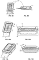
- a light output window cap in the form of a skin spacer cap 17 is provided in the embodiment depicted in Figures 10a, 10b .
- the skin spacer cap 17 is positioned at the application head 2 at the side of a window 7 facing away from the light source.
- the contact area between the skin spacer cap 17 and the window 7 and further component parts of of the application head 2 may be minimized by having only small fixation contacts.
- a small gap 18 may be provided between the skin spacer cap 17 and the window 7.
- the heat transfer from the light source 3 to the skin of a user may be further minimized by reducing the contact area 19 of the skin spacer cap 17 and the user's skin.
- a gel cushion 20 may be provided between the window 7 and the user's skin as depicted in Figures 11a, 11b .
- the additional gel cushion 20 is placed in front of the light output window 7.
- the gel has a high light-transmissivity for visible and NIR-light and is encased by flexible and transparent foil.
- the attachment for example the skin spacer cap 17, has no contact to the window 7, except for some fixation contacts.
- a small gap 18 between gel cushion attachment and window 7 reduces the conductance of the warm window 7 to the gel cushion 20.
- FIG 12 depicts a schematic embodiment of a detail of a skin treatment device with a light source 3 which is a heat source and cooling fins 4 which are the heat sink.
- the light source 3 and the cooling fins 4 are connected to each other by means of a heat transfer system 6 comprising a first heat conductor 6' and a second heat conductor 6" which are connected via a hinge 21, for example a torque hinge.
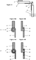
- the hinge may comprise a spindle 22 and the jack 23 as depicted in Figures 13a to 14b with the spindle 22 being connected to the second heat conductor 6" and the jack 23 being connected to the first heat conductor 6'.
- the first heat conductor 6' and the second heat conductor 6" are further thermally connected by means of a PGS 24 forming a flexible part 13 of the heat transfer system 6.
- the first (upper) heat conductor 6' may be just a plate of a good heat conducting material, e.g. copper or alumina, a heat pipe 6 or directly an extended area of the PGS sheet 24.
- the heat from the heat source 3 in the head 2 is transferred via the upper heat conductor 6' to the flexible part 13 of the heat conductor which may be a PGS foil.
- the hinge 21 of Figure 12 mainly serves for mechanical stability, whereas heat conductivity of hinge 21 may be relatively insignificant.
- the length of the PGS foil 24 between the upper and the lower heat conductors 6', 6" is preferably low. It is desired to keep this length as low as possible, for example at a length below 10 mm, in order to keep the temperature difference over the length of the unsupported part of the foil 24 close to the hinge 21 low.
- the lower heat conductor 6" may also be directly the heat sink (copper, alumina with fins 4) or a heat pipe 6 to allow heat transfer to the remotely located heat sink 4.
- Another option to transfer the heat from the head 2 to the body or handle 1 is using a specially designed hinge 21 which has the capability to transfer sufficient heat.
- Figures 13a and 13b depict an alternative embodiment of a hinge 21 suitable for swiveling application head 2 with respect to the handle 1 of the skin treatment device while allowing sufficient heat transfer.
- Figures 13a and 13b show the hinge 21 build of two heat pipes each forming one of the upper and the lower heat conductors 6', 6".
- the cylindrical contact area between spindle 22 and jack 23 transfers the heat from the spindle 22 to the jack 23.
- heat conducting lubricant may be used.
- Figures 14a and 14b depict a further alternative embodiment of a hinge 21 suitable for swiveling application head 2 with respect to the handle 1 of the skin treatment device while allowing sufficient heat transfer.
- Figures 14a and 14b show a design using on the jack side 23 a PGS 24 as a heat conductor.
- the spindle 22 is again made using heat pipe technology.
Landscapes
- Health & Medical Sciences (AREA)
- Engineering & Computer Science (AREA)
- Life Sciences & Earth Sciences (AREA)
- Biomedical Technology (AREA)
- General Health & Medical Sciences (AREA)
- Physics & Mathematics (AREA)
- Nuclear Medicine, Radiotherapy & Molecular Imaging (AREA)
- Public Health (AREA)
- Veterinary Medicine (AREA)
- Animal Behavior & Ethology (AREA)
- Pathology (AREA)
- Radiology & Medical Imaging (AREA)
- Surgery (AREA)
- Optics & Photonics (AREA)
- Biophysics (AREA)
- Molecular Biology (AREA)
- Medical Informatics (AREA)
- Sustainable Development (AREA)
- Thermal Sciences (AREA)
- Mechanical Engineering (AREA)
- General Engineering & Computer Science (AREA)
- Pain & Pain Management (AREA)
- Heart & Thoracic Surgery (AREA)
- Otolaryngology (AREA)
- Electromagnetism (AREA)
- Radiation-Therapy Devices (AREA)
- Thermotherapy And Cooling Therapy Devices (AREA)
Abstract
Description
- The present invention is concerned with a skin treatment device, for example a hand-held hair removal device. The device may comprise a handle with an energy supply, an application head with at least one heat source comprising at least one semiconductor light source, and at least one heat sink comprising cooling fins.
- It is known to use skin treatment devices using semiconductor light sources for hair removal. For example,
EP 1 771 121 B1 - Every light based device inherently generates heat and the light source heats up. High temperatures of the light source may lead to a performance loss. Thus, an efficient cooling system is necessary to get a high performance light based hair removal device. Heat conductors in cooling systems spread and conduct heat quickly away from a heat source to cooling fins. Known cooling systems use for example a solid copper or aluminum bar for conducting heat from a heat source to cooling fins. However, this increases the weight of a skin treatment device, which is undesired. In addition, efficient use of such cooling systems is limited to transferring heat over short distances only which also limits efficiency of the light output power.
- Further,
US 2005/0231983 A1 discloses an LED curing device having a rigid body with an end tip comprising the LED and a fan located at an opposite end of the body. A heat pipe extending through the body is bonded or glued with one end to the LED and with an opposite end to a heat sink near the fan. The fan blows air over the heat sink. - It is an object of the present disclosure to provide skin treatment device with an improved heat transfer system.
- A skin treatment device is provided comprising a handle with an energy supply, an application head with at least one heat source comprising at least one semiconductor light source, and at least one heat sink comprising cooling fins, wherein the heat sink is located remote from the heat source within the handle, and wherein the heat source is thermally connected to the heat sink by means of a heat pipe heat transfer system. In more detail, the heat transfer system may comprise a hermetically sealed tubular body containing a working medium, wherein the pressure within the tubular body is chosen such that the working medium is a saturated liquid at room temperature and may be vaporized by the heat source. A wick structure may be located in the tubular body exerting a capillary action on the working fluid, i.e. for transporting the liquid from the condensation area (heat sink) to the evaporation area (heat source). Wick structures suitable for heat pipes include sintered metal powder, screen, and grooved wicks, which have a series of grooves parallel to the pipe axis. Depending on the geometry of the tubular body, provision of a wick is not required. For example, a heat pipe may have a configuration and/or coating provided on the inner walls for providing a capillary action. High heat conductance in conjunction with the fact that heat pipes are lightweight enables the possibility to spatially separate heat source and heat sink over higher distances.
- In accordance with one aspect the application head may be sealed, e.g. hermetically, without openings to the ambience and may comprise at least one air channel adapted for guiding air to the at least one semiconductor light source. The at least one air channel may have at least one inlet opening which is located in the handle and at least one outlet opening which is located in the handle.
- In addition or as an alternative, in accordance with a further aspect the application head may be pivotably connected to the handle.
-
- Figure 1
- shows a sectional view of a skin treatment device according to a first embodiment;
- Figure 2
- shows a sectional view of a skin treatment device according to a second embodiment;
- Figure 3
- shows a partial sectional view of a skin treatment device according to a third embodiment;
- Figure 4
- shows a partial sectional view of a skin treatment device according to a fourth embodiment;
- Figure 5
- shows a perspective view of a heat transfer system according to the invention;
- Figures 6a-c
- show different positions of the application head relative to the handle;
- Figure 7
- shows an alternative to
Figures 6a-c ; - Figure 8a
- shows a partial top view of a detail of a skin treatment device according to a fifth embodiment;
- Figure 8b
- shows a perspective view of the heat transfer system of
Figure 8a ; - Figures 9a, b
- show in partial perspective and sectional views details of a skin treatment device according to a sixth embodiment;
- Figures 10a, b
- show in partial perspective and sectional views details of a skin treatment device according to a seventh embodiment;
- Figures 11a, b
- show in partial perspective and sectional views details of a skin treatment device according to an eighth embodiment;
- Figure 12
- show details of a hinge in a skin treatment device according to a further embodiment;
- Figures 13a, b
- show details of a hinge in a skin treatment device according to a further embodiment; and
- Figures 14a, b
- show details of a hinge in a skin treatment device according to a further embodiment.
- Heat pipes in different base shapes of the tubular body, for example round or flat, are suitable for use in the skin treatment device. In particular, the heat pipes may have a rectangular shape. The tubular body of the heat transfer system may be made from a thermally conductive material, especially copper, steel or aluminum. The working medium of the heat transfer system may be a fluid, like a refrigerant, for example water, ammonia or 1,1,1,2-Tetrafluoroethane (R-134a).
- The energy supply may comprise an energy storage, like a battery, in particular a rechargeable battery, located in the handle. In addition or alternatively, the energy may be provided via a mains cable. Optionally, the heat source is electrically connected to the energy supply by means of the tubular body of the heat pipe heat transfer system.
- The heat source of the skin treatment device may comprise light source suitable for hair removal. For example, the heat source may comprise a vertical-cavity surface-emitting laser (VCSEL) array, a vertical external cavity surface-emitting laser (VECSEL) array, a light emitting diode (LED) array and/or an organic light emitting diode (OLED) array.
- The heat sink of the skin treatment device may comprise an appliance for increasing heat transfer from the heat source. For example at least one cooling fan may be provided to raise heat dissipation. In addition or alternatively, at least one thermoelectric element may be provided.
- The application head may be sealed, in particular the head may be mechanically sealed without any openings. With such an environmental encapsulated head design the head is protected against environmental influences like dust, humidity, water, or lotion. In this case, the heat sink, including an optional fan, the cooling air inlets and outlets may be completely placed in the handle.
- For some applications it may be desirable if the application head is rigidly connected to the handle. In addition, the use of, for example, rigid copper material for the tubular body of the heat pipe sets limits movements of the head relative to the handle. However, it is possible to bend heat pipes in required shapes. This characteristic enables more industrial design freedom between head and handle. The angle between the center line of the head and the center line of the handle may be chosen ± 60°. This allows an exposed head with a fixed angle between handle and head. Handling of the hand-held device improves, due to design freedom to get an optimal angle between handle and head for best intended device usability.
- Alternatively, the application head may be pivotably connected to the handle. For example, heat pipes with an additional flexible segment enable designing a device with exposed swivel head. Heat conductors with an additional flexible segment enable designing a device with exposed swivel head. The head may be mechanically connected to the device body (handle) via a constant torque hinge, for example as typically used for notebook displays. This hinge separates the heat conductive means from the mechanical means. The constant torque hinge allows changing the angle while maintaining sufficient rigidity of the device for use without unintended change of the head-body angle. When providing a swiveling connection the heat conductivity of the connection is very important. A typical mechanical hinge even if made of copper or alumina may not have sufficient heat conductivity to meet the requirements for a device with extensive heat load within the device head.
- An important aspect is the solution how to enable sufficient heat transport from the heat source in the application head to the heat sink in the handle or body while having a swiveling connection between both parts. A heat pipe may be made flexible by inserting a flexible segment between the heat source and heat cooling fins section. The flexible segment accommodates any relative motion between heat source and heat sink. An example for such a flexible segment is a flexible bellows section of a heat pipe arranged between the application head and the handle. As a further example, a flexible segment may comprise a highly heat conducting graphite foil, e.g. a pyrolytic graphite sheet (PGS), between the application head and the handle, e.g. connected to the heat source part and the heat sink part of the cooling system. Flexible heat pipes work in principle equivalent to the rigid heat pipes. This additional feature increases the usability of the device, because head orientation to skin adapts better to body shape while usage.
- In addition or as an alternative, the application head may be pivotably connected to the handle by means of a heat conducting hinge having a spindle and a jack. The spindle may comprise a portion of the tubular body of a heat transfer system and the jack may comprise a portion of the tubular body of a heat transfer system or a pyrolytic graphite sheet (PGS). In other words, the heat transfer system may comprise a first heat pipe being part of the spindle and a second heat pipe being part of the jack. As an alternative, a heat pipe is part of the spindle and a pyrolytic graphite sheet is part of the jack.
- According to one aspect, the application head of the skin treatment device further comprises a transparent or translucent skin contact window. Such a skin contact window prevents direct contact of the user's skin to the light source and further prevents environmental influences like dust, humidity, water, or lotion.
- During operation a light source module, for example a LED light source module, may generate up to 75W heat power and the surface of the light source module could heat up to about 80°C. A part of the heat power is heating up the skin contact window. The higher the skin contact window temperature is the more uncomfortable is the usage for the user. To prevent high temperatures at outside surface of the skin contact window, active cooling of the skin contact window and/or thermally decoupling of the window from the heat source is desirable.
- In this respect, a first side of the at least one semiconductor light source may be thermally connected to the heat transfer system and a second side of the at least one semiconductor light source which is opposite the first side may be located within the application head at a position and orientation permitting light to be emitted from the at least one semiconductor light source through the skin contact window. In other words, the heat pipe heat transfer system is arranged such that heat is transferred from the side facing away of the skin contact window from the heat source, i.e. the semiconductor light source.
- In addition or as an alternative, the skin contact window may be thermally connected to the heat transfer system or it may be thermally connected to an additional heat transfer system. The additional heat transfer system may be a heat pipe heat transfer system which comprises for example a hermetically sealed tubular body containing a working medium wherein the pressure within the tubular body is chosen such that the working medium is a saturated liquid at room temperature which may be vaporized by the heat source. In other words, the skin contact window cooling design may comprise connection of the glass or ceramic window to a separate second heat pipe with a heat conductive frame, for example pre-stamped and/or with an applicable heat conductive gap filler, e.g. filled silicon rubber or graphite based filler). The window may be made of a good heat conducting material, like ceramic, sapphire or the like. Within the handle of the skin treatment device, the semiconductor light source and the skin contact window may each have a separate heat sink, for example separate cooling fins. As an alternative, the semiconductor light source and the skin contact window may share one common heat sink. Two different fans may be provided for separate heat sinks. However, even with two separate heat sinks, it is preferred to provide only one single fan which serves both cooling systems.
- The skin contact window may be directly connected with a heat transfer system. However, for providing a homogeneous and higher performance heat flow the skin contact window may be thermally connected to the heat transfer system or to the additional heat transfer system by means of a thermoelectric cooler. For example, this skin contact window cooling system comprises a Peltier element placed between the heat pipe and the inner side of the skin contact window. A Peltier element is an active heat conduction element which enables homogeneous and high performance heat flow from low to high temperature sections. Provision of a thermoelectric cooler, like a Peltier element, facilitates heat transfer from the light source and from the skin contact window using only one single heat pipe to cool both, the LED module or the like light source and the skin contact window at lower temperature at the same time.
- In addition to transferring heat from the skin contact window to the handle or as an alternative, the application head may comprise cooling fins which are thermally connected to the skin contact window. For example, the skin contact window cooling system comprises a head housing made of a heat conductive material, e.g. aluminum or specific filled plastic, which is connected to the skin contact window directly or via a conductive frame. In other words, the application head housing may serve as a heat sink, for example as a heat capacitor and/or with additional cooling fins. Heat sink fins can be integrated in the application head housing, i.e. the application head housing and cooling fins are one component part. Alternatively, cooling fins may be fitted at the rear side of the head that is the side facing away from the skin contact window. This design supports an encapsulated application head design.
- Further or as an alternative, the application head may comprise at least one air channel adapted for guiding air through a gap between the at least one semiconductor light source and the skin contact window. The skin contact window cooling system may comprise an air channel between the application head and the handle. A function of the channel is to suck heated air from the gap area between the light source and the skin contact window by means of a fan which may be placed in the handle. The working principle of this fan is to suck air from one side (inlet side) and to create overpressure at the opposite side (outlet side). At the suction or inlet side the fan generates a negative pressure, i.e. a vacuum. With the fan located in the handle and the handle connected to the application head via an air channel, vacuum generated by the fan in the handle sucks in air of ambient pressure from the application head area via the air channel, thereby generating an air exchange from the application head to the handle. This working principle requires a connection of the application head to the ambient pressure to supply the head with fresh cooling air.
- In general, the at least one air channel may comprise at least one inlet opening which is located in the applicator head and/or in the handle and at least one outlet opening which is located in the applicator head and/or in the handle. For example, a fresh air inlet for window cooling and/or interruption of heat flow to the window from the light source is located in the handle which is directly connected to the application head. In some embodiments, the application head may include air guiding walls to lead the air between the light source and the skin contact window. A second channel connection to the handle may suck the heated air due to vacuum generated by the fan in the handle. Due to sealed head design, it is possible to use a lotion or the like liquid with the skin treatment device. Alternatively, a fresh air inlet for head cooling is located in the application head itself. For example, the application head includes air support walls to lead the air between the light source and the skin contact window. In some embodiments, only one cooling channel between the application head and the handle may be sufficient. Due to this non-encapsulated head design, the use of a lotion or the like liquid together with the device is limited. The cooling air channels may be integrated in the handle and/or in the head housing or may be provided as an extra part, e.g. extra build-in pipe channels.
- Still further, the applicator head may comprise a fan adapted to pass air through the air channel. In more detail, the skin contact window cooling system may comprise a non-encapsulated design of the application head with small openings and a small fan integrated in the head. Continuous exchange of fresh air between the skin contact window and the light source module prevents that the heat emitted by the light source module heats up the skin contact window to a temperature level which is unpleasant for the user. Usability of lotion or the like is limited due to the non-encapsulated head.
- The light output area may be designed such that a window is provided which does not directly contact a user's skin. For example, an additional cap, which is placed in front of the light output area, i.e. a window, prevents during usage a contact between the skin and the window. According to one aspect, the cap has no contact to the window, except some possible fixation contact points. This provides a small air gap between the skin contact cap and the window which prevents heat transfer from the window to the skin spacer cap.
- Such a skin spacer cap may reduce heat transfer from a heated window to the skin due to a reduced contact surface size to the skin. In addition, the cap may keep the skin on distance from the heated window. It may further serve as a light guide for the emitted light. Provision of such a cap may result in that no additional cooling of the window may be required.
- An additional gel-cushion, a gel-cushion attachment, may be placed in front of the light output window. The gel may have a high light-transmissivity for visible and NIR-light and is encased by a flexible and transparent foil. The attachment may have no contact to the window, except of some fixation contacts. A small gap between the gel-cushion attachment and the window prevents or significantly reduces the heat transfer of the warm window to the gel-cushion. A benefit of the gel-cushion is to improve the adaptation of the head to body shapes due flexible properties of the gel-cushion while device usage and the possibility to use lotion or the like liquids together with the skin treatment device.
- The skin treatment device as shown in the
Figure 1 compriseshandle 1 and anapplication head 2. Theapplication head 2 comprises a light source in the form often anLED module 3. The light based device is suitable for skin treatment, especially for applications that need a high intensity light source, and if the light delivery system is desired to be small and light. Possible applications include light based hair removal, light based skin rejuvenation via bio-photo modulation and acne treatment. - The
application head 2 may be designed to be a separate component part which is split from thehandle 1. This results in a better application head adjustment to different body shapes. Further, an environmental encapsulated head design is feasible. The compact size of the application head improves the usage precision for small treatment areas (e.g. face and bikini) by enhancing the visibility of the skin to be treated. - In the skin treatment device of
Figure 1 , an energy supply, for example an energy source in the form of a rechargeable battery (not shown), is provided in thehandle 1. Further, a heat sink in the form ofcooling fins 4 and afan 5 are provided in thehandle 1 allowing transferring heat generated by the light source to the heat sink. Due to high temperatures of the light source resulting in a performance loss of the skin treatment device, efficient heat transfer is desirable. - The
LED module 3 is thermally connected to theheat sink 4 by means of aheat pipe 6. Theheat pipe 6 comprises a tubular body of a flat and substantially rectangular shape which is hermetically sealed. A working medium is located within the tubular body with the pressure of the working medium within the tubular body being chosen such that the working medium is a saturated liquid at room temperature and may be vaporized by the heat source that is of thelight source 3. As can be seen for example fromFigure 5 theheat pipe 6 has thelight source 3 and theheat sink 4 directly applied to the outer surface of the tubular body. Optionally, the tubular body of theheat pipe 6 further electrically connects the energy source with the light source. - In the embodiment of
Figure 1 theapplication head 2 is provided with askin contact window 7 which contacts the user's skin during use of the skin treatment device. Theapplication head 2 is an encapsulated together with theskin contact window 7 to prevent thehead 2 against environmental influences like dust, humidity, water, or lotion. - An air channel is provided in the skin treatment device, which air channel comprises an
inlet 8 located in thehandle 1, apassage 9a from thehandle 1 to thehead 2, afurther passage 9b from thehead 2 to thehandle 1, and anoutlet 10. Thus, ambient air may be sucked in byfan 5 via theinlet 8, floating about thelight source 3 and through achannel 9c between the light source and theskin contact window 7, back into thehandle 1 and throughfan 5 tooutlet 10. In other words,fan 5 not only supplies cooling air tofins 4 but also for coolingskin contact window 7. - An alternative design is depicted in
Figure 2 . In this embodiment, theinlet 8 is provided directly in theapplication head 2. Thus, cooling air is sucked in byfan 5 throughinlet 8, passes through thechannel 9c between the light source and theskin contact window 7, passes along coolingfins 7 and is finally exhausted throughoutlet 10. - A further alternative is depicted in
Figure 3 . In this embodiment theapplication head 2 is provided with aseparate fan 11. Aninlet 8 and anoutlet 10 are located in theapplication head 2 such that cooling air may pass through theapplication head 2 and through thechannel 9c between the light source and the skin contact window. In this embodiment an air passage between thehandle 1 and theapplication head 2 is not required. An air inlet and an air outlet may be provided in thehandle 1 together withfan 5 to supply cooling air tofins 4 as depicted inFigures 1 and 2 . - Still further embodiment is depicted in
Figure 4 . In this embodiment theapplication head 2 is provided as a heat sink for theskin contact window 7. In thisrespect cooling fins 12 may be provided at the side facing away from theskin contact window 7. Heat may be transferred from theskin contact window 7 via the housing of theapplication head 2 to the coolingfins 12 as indicated by arrows inFigure 4 . - Due to the relatively rigid structure of
heat pipe 6, theapplication head 2 may be fixed with respect to thehandle 1. Nevertheless, it is possible to position theapplication head 2 with respect to thehandle 1 in different ways to get an optimal angle between of theapplication head 2 and thehandle 1 for the best intended usability of the handheld skin treatment device.Figures 6a to 6c show exemplary embodiments of different angles between theapplication head 2 and handle 1. For example, the angle α between the center axis of thehandle 1 and theapplication head 2 may be positive as shown inFigure 6a , or 0 as shown inFigure 6b , or negative as shown inFigure 6c . - As an alternative,
heat pipe 6 may be provided with an additionalflexible segment 13 as depicted inFigure 7 . Thisflexible segment 13 permits swiveling between theapplication head 2 and thehandle 1. Theflexible segment 13 may comprise a flexible tube, a corrugated pipe and/or a heat conducting graphite foil. - In more detail, the
flexible segment 13 may be a swiveling head design with aflexible heat pipe 6. Heat pipes may be made flexible by inserting a flexible bellows section between the upper and lower part of the heat conductor/heat pipe. Such a flexible heat pipe is available for example from the company Aavid Thermalloy, LLC under the name Thermacore flexible heat pipe. This additional feature of a swivelingapplication head 2 increases the usability of the device, because adjustment of the head-body angle allows improved handling on difficult to reach body areas. - As an alternative, the
flexible segment 13 for the swiveling head design may comprise a PGS (Pyrolytic Graphite Sheet). Such a PGS has a very high heat conductivity within the plane of the material. The heat conductivity can be up to 5 times higher than the heat conductivity of pure copper. In addition, the PGS material allows bending with very narrow bending radius and high number of bending cycles. Such a PGS is available from the company Panasonic under the name PGS graphite sheet. - To improve heat transfer from the
skin treatment window 7, theskin treatment window 7 may be thermally connected with a separate heat transfer system in the form of aheat pipe 14 as shown inFigures 8a and 8b . Theadditional heat pipe 14 may be connected withseparate cooling fins 15, for example located adjacent to coolingfins 4 ofheat pipe 6.Fan 5 which supplies cooling air tofins 4 may also supply cooling air tofins 15. - As an alternative, the
skin contact window 7 may be provided with a cooling system transferring heat from theskin contact window 7 to thecooling fins 4 by means ofheat pipe 6. In this embodiment it is preferred to provide a thermoelectric cooler, for example aPeltier element 16 as shown inFigures 9a and 9b , interposed between theskin cooling window 7 and theheat pipe 6. - For some applications it may be desirable to prevent direct contact between a user's skin and a
window 7 of the device. As an alternative to a skin contact window 7 a light output window cap in the form of askin spacer cap 17 is provided in the embodiment depicted inFigures 10a, 10b . Theskin spacer cap 17 is positioned at theapplication head 2 at the side of awindow 7 facing away from the light source. The contact area between theskin spacer cap 17 and thewindow 7 and further component parts of of theapplication head 2 may be minimized by having only small fixation contacts. In addition, asmall gap 18 may be provided between theskin spacer cap 17 and thewindow 7. The heat transfer from thelight source 3 to the skin of a user may be further minimized by reducing thecontact area 19 of theskin spacer cap 17 and the user's skin. - In addition or as an alternative, a
gel cushion 20 may be provided between thewindow 7 and the user's skin as depicted inFigures 11a, 11b . Theadditional gel cushion 20 is placed in front of thelight output window 7. The gel has a high light-transmissivity for visible and NIR-light and is encased by flexible and transparent foil. The attachment, for example theskin spacer cap 17, has no contact to thewindow 7, except for some fixation contacts. Asmall gap 18 between gel cushion attachment andwindow 7 reduces the conductance of thewarm window 7 to thegel cushion 20. -
Figure 12 depicts a schematic embodiment of a detail of a skin treatment device with alight source 3 which is a heat source andcooling fins 4 which are the heat sink. Thelight source 3 and thecooling fins 4 are connected to each other by means of aheat transfer system 6 comprising a first heat conductor 6' and asecond heat conductor 6" which are connected via ahinge 21, for example a torque hinge. The hinge may comprise aspindle 22 and thejack 23 as depicted inFigures 13a to 14b with thespindle 22 being connected to thesecond heat conductor 6" and thejack 23 being connected to the first heat conductor 6'. The first heat conductor 6' and thesecond heat conductor 6" are further thermally connected by means of aPGS 24 forming aflexible part 13 of theheat transfer system 6. - In the present embodiment, the first (upper) heat conductor 6' may be just a plate of a good heat conducting material, e.g. copper or alumina, a
heat pipe 6 or directly an extended area of thePGS sheet 24. The heat from theheat source 3 in thehead 2 is transferred via the upper heat conductor 6' to theflexible part 13 of the heat conductor which may be a PGS foil. Thehinge 21 ofFigure 12 mainly serves for mechanical stability, whereas heat conductivity ofhinge 21 may be relatively insignificant. - An aspect of the embodiment of
Figure 12 is that the length of thePGS foil 24 between the upper and thelower heat conductors 6', 6" is preferably low. It is desired to keep this length as low as possible, for example at a length below 10 mm, in order to keep the temperature difference over the length of the unsupported part of thefoil 24 close to thehinge 21 low. Thelower heat conductor 6" may also be directly the heat sink (copper, alumina with fins 4) or aheat pipe 6 to allow heat transfer to the remotely locatedheat sink 4. - Another option to transfer the heat from the
head 2 to the body or handle 1 is using a specially designedhinge 21 which has the capability to transfer sufficient heat. -
Figures 13a and 13b depict an alternative embodiment of ahinge 21 suitable for swivelingapplication head 2 with respect to thehandle 1 of the skin treatment device while allowing sufficient heat transfer.Figures 13a and 13b show thehinge 21 build of two heat pipes each forming one of the upper and thelower heat conductors 6', 6". The cylindrical contact area betweenspindle 22 andjack 23 transfers the heat from thespindle 22 to thejack 23. To increase the heat transfer heat conducting lubricant may be used. -
Figures 14a and 14b depict a further alternative embodiment of ahinge 21 suitable for swivelingapplication head 2 with respect to thehandle 1 of the skin treatment device while allowing sufficient heat transfer.Figures 14a and 14b show a design using on the jack side 23 aPGS 24 as a heat conductor. Thespindle 22 is again made using heat pipe technology. - The dimensions and values disclosed herein are not to be understood as being strictly limited to the exact numerical values recited. Instead, unless otherwise specified, each such dimension is intended to mean both the recited value and a functionally equivalent range surrounding that value. For example, a dimension disclosed as "40 mm" is intended to mean "about 40 mm."
-
- 1
- handle
- 2
- head
- 3
- light source
- 4
- fins
- 5
- fan
- 6
- heat pipe
- 6', 6"
- heat conductor
- 7
- window
- 8
- inlet
- 9a-c
- channel
- 10
- outlet
- 11
- fan
- 12
- fins
- 13
- flexible segment
- 14
- heat pipe
- 15
- fins
- 16
- thermoelectric cooler
- 17
- skin spacer cap
- 18
- gap
- 19
- contact area
- 20
- gel cushion
- 21
- hinge
- 22
- spindle
- 23
- jack
- 24
- PGS
- α
- angle
Claims (15)
- A skin treatment device comprising
a handle (1) comprising an energy supply,
an application head (2) comprising at least one heat source comprising at least one semiconductor light source (3), and
at least one heat sink comprising cooling fins (4),
wherein the heat sink is located remote from the heat source within the handle (1),
and wherein the heat source is thermally connected to the heat sink by means of a heat transfer system (6, 6', 6") which comprises at least one hermetically sealed tubular body containing a working medium, wherein the pressure within the tubular body is chosen such that the working medium is a saturated liquid at room temperature and may be vaporized by the heat source, characterized in that the application head (2) is sealed without openings to the ambience and comprises at least one air channel (9a, 9b, 9c) adapted for guiding air to the at least one semiconductor light source (3), the at least one air channel (9a, 9b, 9c) having at least one inlet opening (8) which is located in the handle (1) and at least one outlet opening (10) which is located in the handle (1). - A skin treatment device, preferably according to claim 1, comprising
a handle (1) comprising an energy supply,
an application head (2) comprising at least one heat source comprising at least one semiconductor light source (3), and
at least one heat sink comprising cooling fins (4),
wherein the heat sink is located remote from the heat source within the handle (1),
and wherein the heat source is thermally connected to the heat sink by means of a heat transfer system (6, 6', 6") which comprises at least one hermetically sealed tubular body containing a working medium, wherein the pressure within the tubular body is chosen such that the working medium is a saturated liquid at room temperature and may be vaporized by the heat source, characterized in that the application head (2) is pivotably connected to the handle (1). - The skin treatment device according to claim 1 or 2, characterized in that the at least one air channel (9a, 9b, 9c) is adapted for guiding air through a gap (9c) between the at least one semiconductor light source (3) and a transparent or translucent skin contact window (7) of the application head (2).
- The skin treatment device according to any of the preceding claims, comprising a skin contact window (7), characterized in that the skin contact window (7) is thermally connected to the heat transfer system (6) or is thermally connected to an additional heat transfer system (14) which comprises an hermetically sealed tubular body containing a working medium wherein the pressure within the tubular body is chosen such that the working medium is a saturated liquid at room temperature which may be vaporized by the heat source.
- The skin treatment device according to claim 4, characterized in that the skin contact window (7) is thermally connected to the heat transfer system (6, 6', 6") or to the additional heat transfer system (14) by means of a thermoelectric cooler (16).
- The skin treatment device according to any of claims 3 to 5, characterized in that the application head (2) comprises cooling fins (12) which are thermally connected to the skin contact window (7).
- The skin treatment device according to any of the preceding claims, characterized in that the heat source is electrically connected to the energy supply by means of at least one tubular body of a heat transfer system (6, 6', 6"; 14).
- The skin treatment device according to any of the preceding claims, characterized in that the heat sink further comprises at least one cooling fan (5).
- The skin treatment device according to any of the preceding claims, characterized in that the applicator head (2) comprises a fan (11) adapted to pass air through the air channel (9a, 9b, 9c).
- The skin treatment device according to any of claims 3 to 9, characterized in that a first side of the at least one semiconductor light source (3) is thermally connected to the heat transfer system (6, 6', 6") and that a second side of the at least one semiconductor light source (3) which is opposite the first side is located within the application head (2) at a position and orientation permitting light to be emitted from the at least one semiconductor light source (3) through the skin contact window (7).
- The skin treatment device according to any of claims 2 to 10, characterized in that the application head (2) is pivotably connected to the handle (1) by means of a constant torque hinge (21).
- The skin treatment device according to any of claims 2 to 11, characterized in that the application head (2) is pivotably connected to the handle (1) by means of a heat conducting hinge (21) having a spindle (22) and a jack (23), wherein the spindle (22) comprises a portion of the tubular body of a heat transfer system (6, 6', 6"; 14) and the jack (23) comprises a portion of the tubular body of a heat transfer system (6, 6', 6"; 14) and/or a pyrolytic graphite sheet (24).
- The skin treatment device according to any of claims 2 to 12, characterized in that the at least one heat transfer system (6, 6', 6"; 14) comprises a pyrolytic graphite sheet (24) between the application head (2) and the handle (1).
- The skin treatment device according to any of claims 2 to 12, characterized in that the at least one heat transfer system (6, 6', 6"; 14) comprises a flexible bellows section (13) between the application head (2) and the handle (1).
- The skin treatment device according to any of the preceding claims, characterized in that the heat source comprises a vertical-cavity surface-emitting laser (VCSEL) array, a vertical external cavity surface-emitting laser (VECSEL) array, a light emitting diode (LED) array or an organic light emitting diode (OLED) array.
Priority Applications (5)
| Application Number | Priority Date | Filing Date | Title |
|---|---|---|---|
| US15/625,008 US20170367761A1 (en) | 2016-06-27 | 2017-06-16 | Skin treatment device |
| JP2018566387A JP6903692B2 (en) | 2016-06-27 | 2017-06-23 | Skin treatment device |
| KR1020187036693A KR102255582B1 (en) | 2016-06-27 | 2017-06-23 | Skin treatment device |
| PCT/IB2017/053764 WO2018002794A2 (en) | 2016-06-27 | 2017-06-23 | Skin treatment device |
| CN201780039974.2A CN109414590B (en) | 2016-06-27 | 2017-06-23 | skin treatment device |
Applications Claiming Priority (1)
| Application Number | Priority Date | Filing Date | Title |
|---|---|---|---|
| EP16176379 | 2016-06-27 |
Publications (3)
| Publication Number | Publication Date |
|---|---|
| EP3263177A2 true EP3263177A2 (en) | 2018-01-03 |
| EP3263177A3 EP3263177A3 (en) | 2018-02-14 |
| EP3263177B1 EP3263177B1 (en) | 2019-06-26 |
Family
ID=56292493
Family Applications (1)
| Application Number | Title | Priority Date | Filing Date |
|---|---|---|---|
| EP17169532.3A Active EP3263177B1 (en) | 2016-06-27 | 2017-05-04 | Skin treatment device |
Country Status (7)
| Country | Link |
|---|---|
| US (1) | US20170367761A1 (en) |
| EP (1) | EP3263177B1 (en) |
| JP (1) | JP6903692B2 (en) |
| KR (1) | KR102255582B1 (en) |
| CN (1) | CN109414590B (en) |
| ES (1) | ES2745124T3 (en) |
| WO (1) | WO2018002794A2 (en) |
Cited By (2)
| Publication number | Priority date | Publication date | Assignee | Title |
|---|---|---|---|---|
| GB2598176B (en) * | 2020-06-19 | 2023-08-16 | Shenzhen Ulike Smart Electronics Co Ltd | Depilator |
| US20230285222A1 (en) * | 2020-08-10 | 2023-09-14 | Park, Won Hee | Handpiece capable of attaching/detaching vacuum cap and adjusting angle of vacuum cap |
Families Citing this family (13)
| Publication number | Priority date | Publication date | Assignee | Title |
|---|---|---|---|---|
| JP7355431B2 (en) * | 2019-08-09 | 2023-10-03 | 深▲せん▼市洋沃電子有限公司 | portable hair removal device |
| CN112533554B (en) * | 2020-04-02 | 2023-09-22 | 深圳市予一电子科技有限公司 | A hair removal device and a semiconductor refrigeration chip |
| US12342920B2 (en) | 2020-06-19 | 2025-07-01 | Shenzhen Ulike Smart Electronics Co., Ltd | Depilator |
| KR200496380Y1 (en) * | 2020-06-19 | 2023-01-13 | 셴젠 유라이크 스마트 일렉트로닉스 컴퍼니 리미티드 | depilator |
| CN111821019B (en) * | 2020-08-05 | 2025-01-14 | 深圳由莱智能电子有限公司 | Hair removal device with dual cooling channels |
| JP3246181U (en) * | 2020-10-21 | 2024-03-28 | 深▲せん▼由莱智能電子有限公司 | epilator |
| CN115790222B (en) * | 2021-09-09 | 2026-01-06 | 珠海德标光电科技有限公司 | A method for fabricating a flexible heat pipe and a flexible heat pipe. |
| CN113983840B (en) * | 2021-09-13 | 2023-12-15 | 江苏大学 | A transplantable bionic sweat gland and intelligent robot with rigid characteristics |
| US20240033000A1 (en) * | 2021-11-02 | 2024-02-01 | Wuhan Lotuxs Technology Co., Ltd. | Handheld home laser hair removal device and system |
| US20230157752A1 (en) * | 2021-11-24 | 2023-05-25 | Filip Sedic | Stimulation Device |
| JP7855296B2 (en) * | 2022-03-25 | 2026-05-08 | 深▲せん▼由莱智能電子有限公司 | Hair removal device |
| JP7557026B2 (en) * | 2022-10-17 | 2024-09-26 | 深▲せん▼市予一電子科技有限公司 | Photon High Frequency Beauty Device |
| JP7375232B2 (en) * | 2022-10-17 | 2023-11-07 | 深▲せん▼市嘉宇康医療器械有限公司 | Semiconductor cooling module and optical beauty device |
Citations (2)
| Publication number | Priority date | Publication date | Assignee | Title |
|---|---|---|---|---|
| US20050231983A1 (en) | 2002-08-23 | 2005-10-20 | Dahm Jonathan S | Method and apparatus for using light emitting diodes |
| EP1771121B1 (en) | 2004-07-09 | 2011-06-22 | Braun GmbH | Manipulation of hair growth |
Family Cites Families (17)
| Publication number | Priority date | Publication date | Assignee | Title |
|---|---|---|---|---|
| US5910883A (en) * | 1997-08-06 | 1999-06-08 | International Business Machines Corporation | Hinge incorporating a helically coiled heat pipe for a laptop computer |
| US5946187A (en) * | 1997-09-23 | 1999-08-31 | International Business Machines Corporation | Heat pipe arrangement for enhancing the cooling capacity of a laptop computer |
| MXPA05001029A (en) * | 2002-07-25 | 2005-09-12 | Jonathan S Dahm | Method and apparatus for using light emitting diodes for curing. |
| US20050055070A1 (en) * | 2003-03-07 | 2005-03-10 | Gareth Jones | Method and device for treatment of skin conditions |
| CA2572548C (en) * | 2004-07-02 | 2014-09-02 | Discus Dental Impressions, Inc. | Dental light devices having an improved heat sink |
| WO2007016634A2 (en) * | 2005-08-02 | 2007-02-08 | Gilson Darcy J | A therapeutic device for delivering controlled air stream flow and/or photodynamic light therapy |
| JP2009022333A (en) * | 2007-07-17 | 2009-02-05 | Shin Nippon Kagaku Seisakusho:Kk | Beauty equipment |
| CN102159151B (en) * | 2008-09-21 | 2014-11-12 | 赛诺龙医疗公司 | Personal skin treatment method and device |
| JP2010142612A (en) * | 2008-12-22 | 2010-07-01 | Panasonic Electric Works Co Ltd | Light application cosmetic apparatus |
| US8518027B2 (en) * | 2009-10-28 | 2013-08-27 | Tria Beauty, Inc. | Phototherapy device thermal control apparatus and method |
| US8834365B2 (en) * | 2010-12-23 | 2014-09-16 | Nlight Photonics Corporation | Skin color and capacitive sensor systems |
| US8475507B2 (en) * | 2011-02-01 | 2013-07-02 | Solta Medical, Inc. | Handheld apparatus for use by a non-physician consumer to fractionally resurface the skin of the consumer |
| US9907612B2 (en) * | 2011-09-06 | 2018-03-06 | Solta Medical, Inc. | Cooled medical handpiece |
| PL2908758T3 (en) * | 2012-10-22 | 2016-12-30 | Electromagnetic skin treatment device | |
| WO2014146029A1 (en) * | 2013-03-15 | 2014-09-18 | Jones Gary W | Multispectral therapeutic light source |
| US10225953B2 (en) * | 2014-10-31 | 2019-03-05 | Thermal Corp. | Vehicle thermal management system |
| US20170304645A1 (en) * | 2016-04-26 | 2017-10-26 | Candela Corporation | Applicator |
-
2017
- 2017-05-04 ES ES17169532T patent/ES2745124T3/en active Active
- 2017-05-04 EP EP17169532.3A patent/EP3263177B1/en active Active
- 2017-06-16 US US15/625,008 patent/US20170367761A1/en not_active Abandoned
- 2017-06-23 JP JP2018566387A patent/JP6903692B2/en active Active
- 2017-06-23 CN CN201780039974.2A patent/CN109414590B/en active Active
- 2017-06-23 WO PCT/IB2017/053764 patent/WO2018002794A2/en not_active Ceased
- 2017-06-23 KR KR1020187036693A patent/KR102255582B1/en active Active
Patent Citations (2)
| Publication number | Priority date | Publication date | Assignee | Title |
|---|---|---|---|---|
| US20050231983A1 (en) | 2002-08-23 | 2005-10-20 | Dahm Jonathan S | Method and apparatus for using light emitting diodes |
| EP1771121B1 (en) | 2004-07-09 | 2011-06-22 | Braun GmbH | Manipulation of hair growth |
Cited By (3)
| Publication number | Priority date | Publication date | Assignee | Title |
|---|---|---|---|---|
| GB2598176B (en) * | 2020-06-19 | 2023-08-16 | Shenzhen Ulike Smart Electronics Co Ltd | Depilator |
| US20230285222A1 (en) * | 2020-08-10 | 2023-09-14 | Park, Won Hee | Handpiece capable of attaching/detaching vacuum cap and adjusting angle of vacuum cap |
| EP4193983A4 (en) * | 2020-08-10 | 2024-10-16 | Won Hee Park | Handpiece capable of attaching/detaching vacuum cap and adjusting angle of vacuum cap |
Also Published As
| Publication number | Publication date |
|---|---|
| EP3263177A3 (en) | 2018-02-14 |
| EP3263177B1 (en) | 2019-06-26 |
| CN109414590B (en) | 2021-05-28 |
| WO2018002794A2 (en) | 2018-01-04 |
| KR102255582B1 (en) | 2021-05-26 |
| KR20190010875A (en) | 2019-01-31 |
| WO2018002794A3 (en) | 2018-03-01 |
| US20170367761A1 (en) | 2017-12-28 |
| CN109414590A (en) | 2019-03-01 |
| JP6903692B2 (en) | 2021-07-14 |
| ES2745124T3 (en) | 2020-02-27 |
| JP2019520901A (en) | 2019-07-25 |
Similar Documents
| Publication | Publication Date | Title |
|---|---|---|
| EP3263177B1 (en) | Skin treatment device | |
| US6709128B2 (en) | Curing system | |
| US8128557B2 (en) | Endoscope with heat dissipating handle | |
| EP2561271B1 (en) | Liquid cooled led lighting device | |
| US8608348B2 (en) | Sealed electrical device with cooling system and associated methods | |
| JP2005521251A (en) | Light emitting device with cooling system | |
| CN219243958U (en) | Semiconductor refrigeration module and optical beauty instrument | |
| CN219083434U (en) | Two-stage refrigeration module and photon beauty instrument | |
| WO2025099453A1 (en) | Cryogenic cooling device | |
| CN108159574B (en) | Spectrum therapeutic instrument | |
| US20230390482A1 (en) | Device for administering medical liquid, having a heat sink with cooling fins | |
| CN218960917U (en) | Dehairing instrument | |
| US6370173B1 (en) | Heat sink for hand-held, high power laser | |
| CN224166396U (en) | Skin care device and care system | |
| US20220418157A1 (en) | Apparatus and method for surface disinfection using uv light | |
| CN201283007Y (en) | Medical handheld light curing device | |
| CN115970172A (en) | Refrigeration module and optical beauty instrument | |
| CN103764334B (en) | There is the mark instrument of at least one gas laser and radiator | |
| CN222983150U (en) | Laser beauty instrument | |
| CN219087666U (en) | Heat sink heat dissipation system embedded with copper pipe | |
| CN219536686U (en) | Radiating assembly and camera | |
| CN220109932U (en) | Eye massage instrument cold and hot module | |
| CN219306920U (en) | Heat dissipation mechanism and laser dehairing instrument | |
| US20110052434A1 (en) | Switch and Motor-Cooling Device for an Electric Fan | |
| JP2015106632A (en) | Electronic device |
Legal Events
| Date | Code | Title | Description |
|---|---|---|---|
| PUAI | Public reference made under article 153(3) epc to a published international application that has entered the european phase |
Free format text: ORIGINAL CODE: 0009012 |
|
| STAA | Information on the status of an ep patent application or granted ep patent |
Free format text: STATUS: THE APPLICATION HAS BEEN PUBLISHED |
|
| AK | Designated contracting states |
Kind code of ref document: A2 Designated state(s): AL AT BE BG CH CY CZ DE DK EE ES FI FR GB GR HR HU IE IS IT LI LT LU LV MC MK MT NL NO PL PT RO RS SE SI SK SM TR |
|
| AX | Request for extension of the european patent |
Extension state: BA ME |
|
| PUAL | Search report despatched |
Free format text: ORIGINAL CODE: 0009013 |
|
| AK | Designated contracting states |
Kind code of ref document: A3 Designated state(s): AL AT BE BG CH CY CZ DE DK EE ES FI FR GB GR HR HU IE IS IT LI LT LU LV MC MK MT NL NO PL PT RO RS SE SI SK SM TR |
|
| AX | Request for extension of the european patent |
Extension state: BA ME |
|
| RIC1 | Information provided on ipc code assigned before grant |
Ipc: A61N 5/06 20060101AFI20180111BHEP |
|
| STAA | Information on the status of an ep patent application or granted ep patent |
Free format text: STATUS: REQUEST FOR EXAMINATION WAS MADE |
|
| 17P | Request for examination filed |
Effective date: 20180814 |
|
| RBV | Designated contracting states (corrected) |
Designated state(s): AL AT BE BG CH CY CZ DE DK EE ES FI FR GB GR HR HU IE IS IT LI LT LU LV MC MK MT NL NO PL PT RO RS SE SI SK SM TR |
|
| GRAP | Despatch of communication of intention to grant a patent |
Free format text: ORIGINAL CODE: EPIDOSNIGR1 |
|
| STAA | Information on the status of an ep patent application or granted ep patent |
Free format text: STATUS: GRANT OF PATENT IS INTENDED |
|
| INTG | Intention to grant announced |
Effective date: 20181221 |
|
| GRAS | Grant fee paid |
Free format text: ORIGINAL CODE: EPIDOSNIGR3 |
|
| GRAA | (expected) grant |
Free format text: ORIGINAL CODE: 0009210 |
|
| STAA | Information on the status of an ep patent application or granted ep patent |
Free format text: STATUS: THE PATENT HAS BEEN GRANTED |
|
| AK | Designated contracting states |
Kind code of ref document: B1 Designated state(s): AL AT BE BG CH CY CZ DE DK EE ES FI FR GB GR HR HU IE IS IT LI LT LU LV MC MK MT NL NO PL PT RO RS SE SI SK SM TR |
|
| REG | Reference to a national code |
Ref country code: GB Ref legal event code: FG4D |
|
| REG | Reference to a national code |
Ref country code: CH Ref legal event code: EP |
|
| REG | Reference to a national code |
Ref country code: AT Ref legal event code: REF Ref document number: 1147616 Country of ref document: AT Kind code of ref document: T Effective date: 20190715 |
|
| REG | Reference to a national code |
Ref country code: DE Ref legal event code: R096 Ref document number: 602017004775 Country of ref document: DE |
|
| REG | Reference to a national code |
Ref country code: IE Ref legal event code: FG4D |
|
| REG | Reference to a national code |
Ref country code: NL Ref legal event code: FP |
|
| PG25 | Lapsed in a contracting state [announced via postgrant information from national office to epo] |
Ref country code: AL Free format text: LAPSE BECAUSE OF FAILURE TO SUBMIT A TRANSLATION OF THE DESCRIPTION OR TO PAY THE FEE WITHIN THE PRESCRIBED TIME-LIMIT Effective date: 20190626 Ref country code: LT Free format text: LAPSE BECAUSE OF FAILURE TO SUBMIT A TRANSLATION OF THE DESCRIPTION OR TO PAY THE FEE WITHIN THE PRESCRIBED TIME-LIMIT Effective date: 20190626 Ref country code: NO Free format text: LAPSE BECAUSE OF FAILURE TO SUBMIT A TRANSLATION OF THE DESCRIPTION OR TO PAY THE FEE WITHIN THE PRESCRIBED TIME-LIMIT Effective date: 20190926 Ref country code: FI Free format text: LAPSE BECAUSE OF FAILURE TO SUBMIT A TRANSLATION OF THE DESCRIPTION OR TO PAY THE FEE WITHIN THE PRESCRIBED TIME-LIMIT Effective date: 20190626 Ref country code: HR Free format text: LAPSE BECAUSE OF FAILURE TO SUBMIT A TRANSLATION OF THE DESCRIPTION OR TO PAY THE FEE WITHIN THE PRESCRIBED TIME-LIMIT Effective date: 20190626 Ref country code: SE Free format text: LAPSE BECAUSE OF FAILURE TO SUBMIT A TRANSLATION OF THE DESCRIPTION OR TO PAY THE FEE WITHIN THE PRESCRIBED TIME-LIMIT Effective date: 20190626 |
|
| REG | Reference to a national code |
Ref country code: LT Ref legal event code: MG4D |
|
| PG25 | Lapsed in a contracting state [announced via postgrant information from national office to epo] |
Ref country code: RS Free format text: LAPSE BECAUSE OF FAILURE TO SUBMIT A TRANSLATION OF THE DESCRIPTION OR TO PAY THE FEE WITHIN THE PRESCRIBED TIME-LIMIT Effective date: 20190626 Ref country code: LV Free format text: LAPSE BECAUSE OF FAILURE TO SUBMIT A TRANSLATION OF THE DESCRIPTION OR TO PAY THE FEE WITHIN THE PRESCRIBED TIME-LIMIT Effective date: 20190626 Ref country code: GR Free format text: LAPSE BECAUSE OF FAILURE TO SUBMIT A TRANSLATION OF THE DESCRIPTION OR TO PAY THE FEE WITHIN THE PRESCRIBED TIME-LIMIT Effective date: 20190927 Ref country code: BG Free format text: LAPSE BECAUSE OF FAILURE TO SUBMIT A TRANSLATION OF THE DESCRIPTION OR TO PAY THE FEE WITHIN THE PRESCRIBED TIME-LIMIT Effective date: 20190926 |
|
| REG | Reference to a national code |
Ref country code: AT Ref legal event code: MK05 Ref document number: 1147616 Country of ref document: AT Kind code of ref document: T Effective date: 20190626 |
|
| PG25 | Lapsed in a contracting state [announced via postgrant information from national office to epo] |
Ref country code: PT Free format text: LAPSE BECAUSE OF FAILURE TO SUBMIT A TRANSLATION OF THE DESCRIPTION OR TO PAY THE FEE WITHIN THE PRESCRIBED TIME-LIMIT Effective date: 20191028 Ref country code: SK Free format text: LAPSE BECAUSE OF FAILURE TO SUBMIT A TRANSLATION OF THE DESCRIPTION OR TO PAY THE FEE WITHIN THE PRESCRIBED TIME-LIMIT Effective date: 20190626 Ref country code: CZ Free format text: LAPSE BECAUSE OF FAILURE TO SUBMIT A TRANSLATION OF THE DESCRIPTION OR TO PAY THE FEE WITHIN THE PRESCRIBED TIME-LIMIT Effective date: 20190626 Ref country code: RO Free format text: LAPSE BECAUSE OF FAILURE TO SUBMIT A TRANSLATION OF THE DESCRIPTION OR TO PAY THE FEE WITHIN THE PRESCRIBED TIME-LIMIT Effective date: 20190626 Ref country code: EE Free format text: LAPSE BECAUSE OF FAILURE TO SUBMIT A TRANSLATION OF THE DESCRIPTION OR TO PAY THE FEE WITHIN THE PRESCRIBED TIME-LIMIT Effective date: 20190626 Ref country code: AT Free format text: LAPSE BECAUSE OF FAILURE TO SUBMIT A TRANSLATION OF THE DESCRIPTION OR TO PAY THE FEE WITHIN THE PRESCRIBED TIME-LIMIT Effective date: 20190626 |
|
| REG | Reference to a national code |
Ref country code: ES Ref legal event code: FG2A Ref document number: 2745124 Country of ref document: ES Kind code of ref document: T3 Effective date: 20200227 |
|
| PG25 | Lapsed in a contracting state [announced via postgrant information from national office to epo] |
Ref country code: SM Free format text: LAPSE BECAUSE OF FAILURE TO SUBMIT A TRANSLATION OF THE DESCRIPTION OR TO PAY THE FEE WITHIN THE PRESCRIBED TIME-LIMIT Effective date: 20190626 Ref country code: IT Free format text: LAPSE BECAUSE OF FAILURE TO SUBMIT A TRANSLATION OF THE DESCRIPTION OR TO PAY THE FEE WITHIN THE PRESCRIBED TIME-LIMIT Effective date: 20190626 Ref country code: IS Free format text: LAPSE BECAUSE OF FAILURE TO SUBMIT A TRANSLATION OF THE DESCRIPTION OR TO PAY THE FEE WITHIN THE PRESCRIBED TIME-LIMIT Effective date: 20191026 |
|
| PG25 | Lapsed in a contracting state [announced via postgrant information from national office to epo] |
Ref country code: TR Free format text: LAPSE BECAUSE OF FAILURE TO SUBMIT A TRANSLATION OF THE DESCRIPTION OR TO PAY THE FEE WITHIN THE PRESCRIBED TIME-LIMIT Effective date: 20190626 |
|
| PG25 | Lapsed in a contracting state [announced via postgrant information from national office to epo] |
Ref country code: PL Free format text: LAPSE BECAUSE OF FAILURE TO SUBMIT A TRANSLATION OF THE DESCRIPTION OR TO PAY THE FEE WITHIN THE PRESCRIBED TIME-LIMIT Effective date: 20190626 Ref country code: DK Free format text: LAPSE BECAUSE OF FAILURE TO SUBMIT A TRANSLATION OF THE DESCRIPTION OR TO PAY THE FEE WITHIN THE PRESCRIBED TIME-LIMIT Effective date: 20190626 |
|
| PG25 | Lapsed in a contracting state [announced via postgrant information from national office to epo] |
Ref country code: IS Free format text: LAPSE BECAUSE OF FAILURE TO SUBMIT A TRANSLATION OF THE DESCRIPTION OR TO PAY THE FEE WITHIN THE PRESCRIBED TIME-LIMIT Effective date: 20200224 |
|
| REG | Reference to a national code |
Ref country code: DE Ref legal event code: R097 Ref document number: 602017004775 Country of ref document: DE |
|
| PLBE | No opposition filed within time limit |
Free format text: ORIGINAL CODE: 0009261 |
|
| STAA | Information on the status of an ep patent application or granted ep patent |
Free format text: STATUS: NO OPPOSITION FILED WITHIN TIME LIMIT |
|
| PG2D | Information on lapse in contracting state deleted |
Ref country code: IS |
|
| 26N | No opposition filed |
Effective date: 20200603 |
|
| PG25 | Lapsed in a contracting state [announced via postgrant information from national office to epo] |
Ref country code: SI Free format text: LAPSE BECAUSE OF FAILURE TO SUBMIT A TRANSLATION OF THE DESCRIPTION OR TO PAY THE FEE WITHIN THE PRESCRIBED TIME-LIMIT Effective date: 20190626 |
|
| PG25 | Lapsed in a contracting state [announced via postgrant information from national office to epo] |
Ref country code: LI Free format text: LAPSE BECAUSE OF NON-PAYMENT OF DUE FEES Effective date: 20200531 Ref country code: MC Free format text: LAPSE BECAUSE OF FAILURE TO SUBMIT A TRANSLATION OF THE DESCRIPTION OR TO PAY THE FEE WITHIN THE PRESCRIBED TIME-LIMIT Effective date: 20190626 Ref country code: CH Free format text: LAPSE BECAUSE OF NON-PAYMENT OF DUE FEES Effective date: 20200531 |
|
| REG | Reference to a national code |
Ref country code: BE Ref legal event code: MM Effective date: 20200531 |
|
| PG25 | Lapsed in a contracting state [announced via postgrant information from national office to epo] |
Ref country code: LU Free format text: LAPSE BECAUSE OF NON-PAYMENT OF DUE FEES Effective date: 20200504 |
|
| PG25 | Lapsed in a contracting state [announced via postgrant information from national office to epo] |
Ref country code: IE Free format text: LAPSE BECAUSE OF NON-PAYMENT OF DUE FEES Effective date: 20200504 |
|
| PG25 | Lapsed in a contracting state [announced via postgrant information from national office to epo] |
Ref country code: BE Free format text: LAPSE BECAUSE OF NON-PAYMENT OF DUE FEES Effective date: 20200531 |
|
| PG25 | Lapsed in a contracting state [announced via postgrant information from national office to epo] |
Ref country code: MT Free format text: LAPSE BECAUSE OF FAILURE TO SUBMIT A TRANSLATION OF THE DESCRIPTION OR TO PAY THE FEE WITHIN THE PRESCRIBED TIME-LIMIT Effective date: 20190626 Ref country code: CY Free format text: LAPSE BECAUSE OF FAILURE TO SUBMIT A TRANSLATION OF THE DESCRIPTION OR TO PAY THE FEE WITHIN THE PRESCRIBED TIME-LIMIT Effective date: 20190626 |
|
| PG25 | Lapsed in a contracting state [announced via postgrant information from national office to epo] |
Ref country code: MK Free format text: LAPSE BECAUSE OF FAILURE TO SUBMIT A TRANSLATION OF THE DESCRIPTION OR TO PAY THE FEE WITHIN THE PRESCRIBED TIME-LIMIT Effective date: 20190626 |
|
| REG | Reference to a national code |
Ref country code: FR Ref legal event code: PLFP Year of fee payment: 7 |
|
| P01 | Opt-out of the competence of the unified patent court (upc) registered |
Effective date: 20230430 |
|
| PGFP | Annual fee paid to national office [announced via postgrant information from national office to epo] |
Ref country code: NL Payment date: 20250409 Year of fee payment: 9 |
|
| PGFP | Annual fee paid to national office [announced via postgrant information from national office to epo] |
Ref country code: DE Payment date: 20250402 Year of fee payment: 9 |
|
| PGFP | Annual fee paid to national office [announced via postgrant information from national office to epo] |
Ref country code: ES Payment date: 20250603 Year of fee payment: 9 |
|
| PGFP | Annual fee paid to national office [announced via postgrant information from national office to epo] |
Ref country code: FR Payment date: 20250401 Year of fee payment: 9 |
|
| PGFP | Annual fee paid to national office [announced via postgrant information from national office to epo] |
Ref country code: GB Payment date: 20260313 Year of fee payment: 10 |