EP3263051A1 - Bone plate fixation system - Google Patents
Bone plate fixation system Download PDFInfo
- Publication number
- EP3263051A1 EP3263051A1 EP17159750.3A EP17159750A EP3263051A1 EP 3263051 A1 EP3263051 A1 EP 3263051A1 EP 17159750 A EP17159750 A EP 17159750A EP 3263051 A1 EP3263051 A1 EP 3263051A1
- Authority
- EP
- European Patent Office
- Prior art keywords
- bone plate
- apertures
- jig
- masking cover
- holes
- Prior art date
- Legal status (The legal status is an assumption and is not a legal conclusion. Google has not performed a legal analysis and makes no representation as to the accuracy of the status listed.)
- Granted
Links
Images







Classifications
-
- A—HUMAN NECESSITIES
- A61—MEDICAL OR VETERINARY SCIENCE; HYGIENE
- A61B—DIAGNOSIS; SURGERY; IDENTIFICATION
- A61B17/00—Surgical instruments, devices or methods
- A61B17/56—Surgical instruments or methods for treatment of bones or joints; Devices specially adapted therefor
- A61B17/58—Surgical instruments or methods for treatment of bones or joints; Devices specially adapted therefor for osteosynthesis, e.g. bone plates, screws or setting implements
- A61B17/68—Internal fixation devices, including fasteners and spinal fixators, even if a part thereof projects from the skin
- A61B17/80—Cortical plates, i.e. bone plates; Instruments for holding or positioning cortical plates, or for compressing bones attached to cortical plates
-
- A—HUMAN NECESSITIES
- A61—MEDICAL OR VETERINARY SCIENCE; HYGIENE
- A61B—DIAGNOSIS; SURGERY; IDENTIFICATION
- A61B17/00—Surgical instruments, devices or methods
- A61B17/16—Instruments for performing osteoclasis; Drills or chisels for bones; Trepans
- A61B17/17—Guides or aligning means for drills, mills, pins or wires
- A61B17/1728—Guides or aligning means for drills, mills, pins or wires for holes for bone plates or plate screws
Definitions
- the present disclosure relates to the fixation of orthopaedic structures to bones. More particularly, the present disclosure relates to jigs used in conjunction with bone plates in minimally invasive surgery (MIS).
- MIS minimally invasive surgery
- Bone plates are used in a variety of surgical procedures, such as to treat fractures of bones in the body.
- an elongate bone plate with a plurality of fixation holes along its extent may be used to affix the bone plate to multiple bone fragments of a fractured bone.
- the bone plate bridges the gaps created between bone fragments, i.e., the fracture gaps, thereby providing support for the fractured bone and aiding in the healing process.
- Insertion and affixation of a bone plate to a fractured bone may be accomplished with minimally invasive surgery ("MIS").
- MIS methods of bone plate fixation can include making a small incision at or near an end of a fractured bone, so that only the end of the bone is exposed to the surgeon.
- a bone plate may then be inserted through the incision such that a bone contacting surface of the bone plate abuts the relevant bone fragments, with the length of the bone plate spanning at least a portion of the length of the fractured bone and bridging the fracture gap.
- the bone plate is affixed to the bone by passing fasteners through the skin, into fixation holes in the bone plate, and into the bone on both sides of the fracture gap.
- This MIS technique can include making stab incisions through the outer layer of skin to provide access for cannulas, which are inserted through the outer layer of skin to span the distance between the incisions and the bone plate fixation holes, so that each cannula corresponds to a respective hole position on the bone plate. A fastener may then be passed through each respective cannula to affix the bone plate to the bone.
- Figs. 1 and 2 are representative of jigs currently utilized.
- jig 12 may be provided to align cannulas (not shown) with respective fixation holes 16 on bone plate 10.
- Jig 12 may be attached to an end portion of plate 10 via fixation arm 20 so that, once plate 10 is positioned properly on a bone, cannulas may be passed through a plurality of holes 14 in jig 12 and advanced toward respective holes 16 in plate 10.
- Holes 14 in jig 12 are positioned and oriented to deliver fasteners to respective plate holes 16 in a desired trajectory.
- jig holes 14 may be laterally offset with respect to corresponding bone plate holes 16, so that respective axes of fasteners passed through the cannulas are directed toward the axis or center of the bone to which plate 10 is attached.
- Jig 12 may be used with shorter bone plates by virtue of jig 12 being useable with plate 10, because the hole patterns of shorter bone plates relative to fixation arm 20 are contained within the hole pattern of plate 10.
- jig 12 may be used with shorter bone plates by using an appropriate number of jig holes 14 closest to fixation arm 20.
- Bone plate 10 has a generally straight or linear overall profile with fixation holes 16 that follow a consistent pattern across the body of plate 10, allowing the shorter bone plates to utilize the same jig holes 14 as the corresponding portion of bone plate 10.
- fixation holes 16 that follow a consistent pattern across the body of plate 10
- jig holes 14 are utilized.
- these jig holes 14 used with a short bone plate correspond with first set 30 of holes 16.
- jig holes 14 disposed between fixation arm 20 and middle marker 24 may be used for a medium length plate. These jig holes 14 correspond with both first set 30 and second set 32 of holes 16 in bone plate 10.
- jig holes 14 disposed between fixation arm 20 and long marker 26 i.e., all of jig holes 14 on jig 12
- bone plate 10 is a long length plate (as shown in Figs. 1 and 2 ).
- These jig holes 14 correspond with first set 30, second set 32, and third set 34 of holes 16 in bone plate 10.
- the present disclosure provides a universal jig compatible with bone plates of varying size, in which different plate sizes having different hole configurations.
- a longer bone plate may have a first hole pattern along a given length thereof, while various shorter bone plates may have differing hole patterns along respective corresponding lengths.
- the universal jig includes a combination of hole groupings to provide a jig hole for each hole in the differing hole patterns of the longer and shorter plates, so that the universal jig is useable with a variety of bone plates having disparate hole patterns.
- a masking cover may be provided to attach to the jig. The masking cover masks off unused jig holes, so that only those jig holes intended for use with a particular bone plate are left exposed.
- the universal jig may, for example, be used with periprosthetic ("PP") bone plates.
- PP bone plates include multiple fixation zones which allow the mounting of one portion of the plate to bone and another portion of the plate to a bone with a prosthesis mounted therein.
- Each fixation zone includes holes in a different geometrical arrangement.
- any particular plate may include a non-periprosthetic zone ("non-PP zone”) with a fixed length and hole configuration, and a periprosthetic zone (“PP zone”) with a length and hole configuration that varies according to the length of the plate.
- the universal jig attaches to the PP bone plate proximate the PP zone, and includes jig holes corresponding to each bone plate hole in both the PP and non-PP zones for a variety of different plate lengths.
- the invention in one form thereof, comprises a bone plate fixation system including a first bone plate with a first bone plate body having a first bone plate longitudinal extent, the first bone plate body including a plurality of holes disposed along a portion of the first bone plate longitudinal extent and arranged in a first bone plate hole configuration.
- the bone plate fixation system further includes a second bone plate with a second bone plate body having a second bone plate longitudinal extent, the second bone plate body including a plurality of second bone plate holes disposed along a portion of the second bone plate longitudinal extent and arranged in a second bone plate hole configuration.
- the portion of the second bone plate longitudinal extent, along which the second bone plate holes are disposed has a length approximately equal to the portion of the first bone plate longitudinal extent, along which the first bone plate holes are disposed.
- the second bone plate hole configuration is different from the first bone plate hole configuration.
- the bone plate fixation further includes a jig including a jig body having a jig body longitudinal extent, with the jig body having a plurality of cannula apertures.
- At least a portion of the plurality of cannula apertures are arranged along a portion of the jig body longitudinal extent to correspond to the first bone plate hole configuration, and at least a portion of the plurality of cannula apertures are arranged along the portion of the jig body longitudinal extent to correspond to the second bone plate hole configuration.
- the jig also includes a fixation arm extending from the jig body, the fixation arm attachable to the first bone plate and the second bone plate.
- the bone plate fixation system allows for the implantation of fasteners to fasten various sizes of bone plate to a bone thereby allowing smaller incisions.
- the invention in another form thereof, comprises a bone plate fixation system including a first bone plate having a first bone plate set of holes, a jig, and a first masking cover.
- the jig includes a jig body with a plurality of cannula apertures, at least a portion of the plurality of cannula apertures positioned so that each hole of the first bone plate set of holes corresponds with a respective one of the plurality of cannula apertures.
- the jig also includes a fixation arm extending away from the jig body, the fixation arm adapted to attach the jig to the first bone plate.
- the bone plate fixation system further includes a first masking cover cooperating with the jig to expose each of the plurality of cannula apertures corresponding to the first bone plate set of holes, with the first masking cover covering each of the plurality of cannula apertures not corresponding to the first bone plate set of holes.
- the invention in a further form thereof, comprises a bone plate fixation system including a first bone plate with a first bone plate body having a first bone plate plurality of holes arranged in a first bone plate hole configuration.
- the bone plate fixation system also includes a jig with a jig body including a plurality of cannula apertures, at least a portion of the plurality of cannula apertures positioned so that each hole of the first bone plate plurality of holes corresponds with a respective one of the plurality of cannula apertures.
- the jig also includes a fixation arm extending away from the jig body, the fixation arm adapted to attach the jig to the first bone plate.
- the bone plate fixation system further includes means for identifying a subset of the plurality of cannula apertures corresponding to the first bone plate plurality of holes.
- universal jigs 100, 400, 500 include longitudinal bodies 102, 402, 502 with fixation arms 104, 404, 504 disposed at and extending away from head portions 106, 406, 506.
- Bodies 102, 402, 502 have upper faces 108, 408, 508 and lower faces 110, 410, 510, with a plurality of cannula apertures 112, 412, 512 extending therebetween.
- Cannula apertures 112, 412, 512 are arranged on body 102, 402, 502 so that each of apertures 112, 412, 512 is distinct from the other apertures 112, 412, 512, such that there is no overlap between the area of one aperture 112, 412, 512 and any other aperture 112, 412, 512.
- Jigs 100, 400, 500 are useable with a variety of different periprosthetic ("PP") bone plates having varying hole patterns and lengths.
- PP periprosthetic
- universal jigs 100, 400, 500 include a combination of hole groupings to provide a jig hole for each hole in the differing hole patterns.
- the following description of universal jigs 100, 400, 500 uses jig 100 as an exemplar. However, it is to be understood that jigs 400, 500, are similar in structure and operation to jig 100 except as otherwise noted.
- apertures 112 may be divided into first set 114 adapted to engage both periprosthetic holes (“PP holes”) and non-periprosthetic holes (“non-PP holes”) depending on plate length, and second set 116 adapted to engage only non-PP holes in a long plate length.
- PP holes 207 are holes in a periprosthetic zone of a bone plate and are arranged in a pattern that facilitates engagement with a bone/prosthetic combination
- non-PP holes 203 are holes in a non-periprosthetic zone of a bone plate and are arranged in a pattern that facilitates engagement with a bone only.
- PP holes 207 and non-PP holes 203 combine to form a variable overall hole pattern on varying lengths of PP bone plates.
- Jig 100 is adapted to engage each of holes 203, as well as each of the holes 207 disposed between attachment area 212 (discussed in detail below) and holes 203, regardless of this variable overall pattern.
- First set 114 of apertures 112 includes first grouping 114a having three apertures 112 arranged in a generally oblique orientation with respect to longitudinal axis 118 of body 102.
- Second, third, fourth and fifth groupings are arranged on body 102 so as to be increasingly distant from head portion 106.
- Groupings 114b, 114c, 114d, 114e each contain a diagonally arranged set of three apertures 112 similar to grouping 114a, and further include two additional apertures 112 flanking the middle hole of the three hole grouping to form an X-shaped pattern similar to the "five side" of a traditional six sided playing die.
- Second set 116 of apertures 112 includes first grouping 116a, second grouping 116b and third grouping 116c, each including two diagonally arranged apertures 112, with first, second and third groupings 116a, 116b, 116c being increasingly distant from head portion 106 and from first set 114 of apertures 112.
- Groupings 116a, 116b, 116c have two apertures 112 arranged in a similar fashion to the additional holes added to first grouping 114a to create the five-hole groupings 114b-114e. As described in more detail below, these arrangements of hole groupings facilitate the use of universal jig 100 with a variety of bone plates having disparate hole patterns.
- universal jigs 400, 500 may be provided with overhangs 422, 522 to accommodate bottom-mounted masking covers 411, 420, 430, 440, 450, 550 ( Figs. 15a-15e and 18A ), as described in detail below.
- Universal jigs 400, 500 may also include K-wire guides 403, 503 ( Figs. 14 and 17 ) formed in bodies 402, 502 of jigs 400, 500.
- K-wire guides 403, 503 may receive a K-wire or other guide wire therethrough, which may then be secured to the bone of a patient in order to fix the positions of bodies 402, 502 of jigs 400, 500 with respect to the bone, as also discussed in detail below.
- universal jig 100 is adapted for use in conjunction with a bone plate to repair a fracture on a right-side bone, such as a right femur.
- a mirror image of jig 100 may be provided to similarly repair a left-side fracture.
- the principles of operation of jig 100 disclosed herein are applicable to the affixation of a bone plate to any bone.
- Periprosthetic bone plates are used for repairing fractures in a bone having an existing or newly implanted prosthesis implanted in the bone.
- periprosthetic zones ("PP zone") 206, 226, 246, 266, 286 include PP holes 207 with a pattern adapted to engage a bone/prosthesis combination, while non-periprosthetic zones 202, 222, 242, 262, 282 include non-PP holes 203 adapted to engage a bone without a prosthesis.
- a relatively smaller number of non-PP holes 203 may be used for a given length of fractured bone without a prosthesis
- a relatively larger number of PP holes 207 may be used for the same length of bone with a prosthesis implanted therein.
- different lengths of a PP bone plates typically have different overall hole patterns.
- Universal jig 100 may be used with PP bone plates including PP zones and non-PP zones, where each zone has a different hole pattern.
- universal jig 100 is adapted to engage five different lengths of PP bone plates, although it is contemplated that the present disclosure may be adapted to engage fewer or more sizes of bone plates as required or desired.
- Exemplary PP bone plates are shown and described in a U.S. Patent Application entitled A PLATE FOR THE TREATMENT OF BONE FRACTURES (Attorney Docket No. ZIM0793), filed on even date herewith, which claims priority from European Patent Application No. EP09008867.5 filed July 7, 2009 , the disclosures of which are hereby expressly incorporated by reference herein in their entireties.
- Short size plate 200 includes non-PP zone 202, transition zone 204 and PP zone 206.
- Non-PP zone 202 includes six non-PP holes 203.
- PP zone 206 includes ten PP holes 207 ( Fig. 12A ), as well as jig orientation/registration holes 214 and jig fixation hole 216 (described below).
- Each of holes 203, 207 extends between bone contacting surface 217 and fixation surface 218.
- PP zone 206 terminates at head portion 208 of plate 200, and tail portion 210 terminates at non-PP zone 202 of plate 200.
- Attachment area 212 is used for the attachment of universal jig 100 to plate 200, as described herein.
- Medium-short size plate 220 similarly includes non-PP zone 222, transition zone 224 and PP zone 226.
- Medium-short plate 220 is similar to short plate 200, except that PP zone 226 includes three additional PP holes (i.e., one additional set of three holes) 207 extending between bone contacting surface 237 and fixation surface 238, as compared to short plate 200. Accordingly, non-PP zone 222 is located further from head portion 228 of plate 200. However, attachment area 212 remains in the same position on plate 220 with respect to head portion 228 as attachment area 212 on plate 200. Plate 220 is therefore longer than plate 200, increasing the distance between non-PP zone 222 and attachment area 212.
- Medium size plate 240 similarly includes non-PP zone 242, transition zone 244 and PP zone 246.
- PP zone 246 includes three additional PP holes (i.e., one additional set of three holes) 207 extending between bone contacting surface 257 and fixation surface 258, as compared with medium-short plate 220.
- attachment area 212 remains in the same position on plate 240 with respect to head portion 248 as attachment area 212 on plates 200 and 220. Plate 240 is therefore longer than plate 220 and further distancing non-PP zone 242 from attachment area 212.
- Medium-long plate 260 similarly includes non-PP zone 262, transition zone 264 and PP zone 266.
- PP zone 266 includes three additional PP holes 207 extending between bone contacting surface 277 and fixation surface 278, as compared with plate 240.
- attachment area 212 remains in the same position on plate 260 with respect to head portion 268 as attachment area 212 on plates 200, 220 and 240.
- Plate 260 is therefore longer than plate 240, and non-PP zone 262 is still further distanced from head portion 268 as compared with head portion 248 and non-PP zone 242 of plate 240.
- Long plate 280 includes non-PP zone 282, transition zone 284 and PP zone 286.
- PP zone 286 includes yet another three additional PP holes 207 extending between bone contacting surface 297 and fixation surface 298, as compared with plate 260.
- Attachment area 212 again remains in the same position on plate 280 with respect to head portion 288 as attachment area 212 on plates 200, 220, 240 and 260.
- Plate 280 is therefore the longest of the five plates illustrated in Figs. 12A-12E , and non-PP zone 282 is still further distanced from head portion 288 as compared with head portion 268 and non-PP zone 262 of plate 260.
- attachment area 212 remains in the same spatial location with respect to respective head portions 208, 228, 248, 268, 288 of each plate.
- a relatively longer PP plate has three additional PP holes 207 disposed between attachment area 212 and the respective transition zones 204, 224, 244, 264, 284, as compared with the next shorter-size plate.
- the consistent positioning of attachment area 212 with respect to head portions 208, 228, 248, 268, 288 facilitates use of various PP plates in an MIS procedure, but also results in a varying spatial relationship of respective non-PP zones 202, 222, 242, 262, 282 with respect to attachment area 212.
- universal jig 100 is suitable for use with all of plates 200, 220, 240, 260, 280.
- no single bone plate utilizes all of apertures 112 in body 102 of universal jig 100.
- one or more masking covers may be provided to mask off unused cannula apertures 112 for a given length and configuration of bone plate.
- masking cover 130 may be provided for use with short plate 200 to mask or cover unused cannula apertures 112 while leaving exposed cannula apertures 112 corresponding to respective holes in non-PP zone 202 and PP zone 206 on plate 200. More particularly, and as shown in Fig.
- masking cover 130 includes a plurality of apertures 132, 132' extending from lower surface 134 to upper surface 136 of masking cover 130, with apertures 132, 132' positioned to provide access to only those cannula apertures 112 used with short plate 200.
- masking cover 130 includes first set of holes 148 ( Figs. 6 and 7 ) comprised of apertures 132', which are positioned to make accessible those cannula apertures 112 in body 102 of jig 100 which correspond to non-PP holes 203 in non-PP zone 202 of short plate 200 ( Fig. 12A ).
- Masking cover 130 further includes second set of holes 149 ( Figs. 6 and 7 ) comprised of apertures 132 adapted to make accessible those cannula apertures 112 which correspond with PP holes 207 in the portion of PP zone 206 between attachment area 212 and transition zone 204 of short plate 200 ( Fig. 12A ).
- Apertures 132, 132' are oversized as compared to cannula apertures 112 to accommodate head portion 138' of stabilization bolt 140 and/or knurled portion 138 of protection sleeve 142 ( Figs. 5 and 6 ) as described in detail below.
- masking cover 130 may further include registration pins 144 which are sized and positioned to engage unused cannula apertures 112 to establish and maintain proper positioning of masking cover 130 on body 102 of jig 100.
- Registration pins 144 may alternatively be sized and positioned to engage dedicated registration holes 365 (as shown in Fig. 3 ).
- registration pins 144 fit in to corresponding holes on body 102 to locate masking cover 130. If masking cover 130 is not properly positioned on body 102, pins 144 will not both fit into corresponding holes on body 102, thereby providing an indication to the user that masking cover 130 needs to be repositioned.
- masking cover 130 may also include a marking or engraving 146 along a perimeter edge of cover 130 to identify a particular bone plate associated with masking cover 130, such as short plate 200, and whether cover 130 is intended for use on a right or left side anatomical structure.
- marking 146 indicates that plate 130 is designed for use with a right-side jig and a 240 mm bone plate at a distal end of a bone (such as, for example, a femur).
- masking cover 150 may be provided for use with universal jig 100 and long plate 280.
- Masking cover 150 is similar to masking cover 130, in that it has a plurality of apertures 152, 152' extending between lower surface 154 and upper surface 156 of cover 150.
- apertures 152, 152' of masking cover 150 vary in configuration and number as compared with apertures 132, 132' of masking cover 130.
- Apertures 152, 152' are, similar to apertures 132, 132', sized to allow knurled portions 138, and/or head portion 138' to pass therethrough.
- Masking cover 150 includes first set of holes 168 comprising apertures 152' ( Figs. 9 and 10 ) adapted to make accessible those cannula apertures 112 in body 102 of jig 100 which correspond to non-PP holes 203 in non-PP zone 282 of long plate 280 ( Fig. 12E ).
- Masking cover 150 further includes second set of holes 169 comprising apertures 152 ( Figs. 9 and 10 ) adapted to make accessible those cannula apertures 112 which correspond with PP holes 207 in the portion of PP zone 286 between attachment area 212 and transition zone 284 of long plate 280 ( Fig. 12E ).
- masking cover 150 may also include a marking or engraving 166 identifying the corresponding bone plate, such as long plate 280, by length and/or anatomical side.
- marking 166 indicates that cover 150 is designed for use with a right-side jig and a 400 mm bone plate at a distal end of a bone, such as a femur.
- At least one registration pin 164 may also be included in at least one location on lower surface 154 of masking cover 150 to facilitate positioning and retention of masking cover 150 on body 102 of jig 100, similar to registration pin 144 of cover 130 (discussed above).
- Masking cover 350 includes apertures 352, and cutouts 352' extending from lower surface 354 to upper surface 356.
- Apertures 352 correspond to PP holes 207 of plate 280, which are similar to apertures 132, 152 of covers 130, 150.
- cutouts 352' correspond to non-PP holes 203 of plate 280, rather than apertures 132', 152' of covers 130, 150. Cutouts 352' are suitable for use with thin masking cover materials because potentially delicate strips of material separating cutouts 352' from a perimeter edge of cover 350 are not included.
- Masking cover 350 includes registration pins 364 at each end of cover 350. Similar to registration pins 144, 164 of covers 130, 150 respectively, pins 364 cooperate with registration holes 365 in body 102 ( Figs. 3 and 4 ) to orient and secure cover 350 to body 102, and to prevent the misalignment of cover 350 on body 102. Unlike pins 144, 164, pins 364 extend from both lower surface 354 and upper surface 356, so that cover 350 is securable to both a right-side jig (such as shown in Fig. 11 ) or a left-side jig (which is a mirror image of right-side jig 100, as discussed above) by flipping cover 350 over. Pins 364 may replace registration pins 144, 164 of covers 130, 150 respectively, or may be used in addition to such registration pins.
- Covers 130, 150 and 350 have been described for short plate 200 and long plate 280. However, the principles of operation for covers 130, 150, 350 also apply in combination with one another, and for use with other lengths and orientations of bone plates.
- masking covers may be provided for medium-short plate 220, medium plate 240, medium-long plate 260, or other periprosthetic bone plates by providing an appropriate number and orientation of respective apertures to correspond with any respective plate.
- Registration pins 144, 164, 364 may also extend from only one side of their respective masking covers to correspond with either a left-side or right-side jig (as shown in Figs.
- registration pins 144, 164, 364 may extend from both sides of their respective masking covers to facilitate use of a single cover for both right-side and left-side jigs (as shown in Fig. 11 with respect to pins 364).
- Universal fixation device 400 ( Figs. 13 and 14 ) is substantially similar to universal fixation device 100, discussed above, with reference numerals of jig 400 having the same numerals used as jig 100 except with 300 added thereto. Structures of jig 400 correspond to identical structures denoted by corresponding reference numerals of jig 100, except as otherwise noted. However, fixation device 400 is specifically adapted to accept bottom-mounted masking covers 411, 420, 430, 440, 450 ( Figs. 15a-15e ). More particularly, fixation device 400 includes overhang 422 disposed between lower face 410 and fixation arm 404, such that slot 423 ( Fig. 14 ) is formed between overhang 422 and lower face 410.
- fixation device 400 For purposes of the following description, the interaction between fixation device 400 and masking covers 411, 420, 430, 440, 450 is described in terms of masking cover 450, which is shown mounted to fixation device 400 in Fig. 13 .
- masking covers 411, 420, 430,440 adapted to leave appropriate cannula holes 412 of fixation device 400 exposed for use with plates 200, 220, 240, 260, respectively, can be mounted to fixation device 400 in a similar fashion.
- Masking cover 450 includes apertures 452 extending from lower surface 454 to upper surface 456, similar to masking covers 150, 350 discussed above. Apertures 452 leave certain ones of cannula holes 412 exposed on lower face 410 of fixation device 400, while covering certain other cannula holes 412. For long-plate masking cover 450, apertures 452 are positioned to correspond with cannula holes 412 in fixation device 400 that are used with long plate 280 ( Fig. 13 ). However, unlike masking covers 150, 350 which are adapted to mounted to upper faces 108 of jig 100, masking cover 450 is adapted to mount to jig 400 at lower face 410.
- Masking cover 450 includes arcuate end 458 adapted to be received within slot 423 formed in jig 400.
- Arcuate end 458 includes concave portion 458a and convex portion 458b, which cooperate with a corresponding profile within slot 423 (not shown) to prevent end 458 from sliding laterally out of slot 423 when end 458 is received therein.
- Opposite end 459 of masking cover 450 is secured to jig 400 by thumbscrew 462 ( Fig. 13 ). Specifically, thumbscrew 462 passes through securement aperture 460 ( Fig. 15e ) and is threadably received in jig body 402. As shown in Figs.
- each of masking covers 411, 420, 430, 440, 450 include arcuate end 458 and securement aperture 460, such that slot 423 and thumbscrew 462 may be used to secure any of masking covers 411, 420, 430, 440, 450 to fixation device 400. While thumbscrew 462 is shown in the illustrated embodiment for attaching masking cover 450 to jig body 402, it is contemplated that other methods of fixation may be used, such as clips, set screws or the like.
- Apertures 452 formed in masking cover 450 may be smaller in diameter as compared to apertures 152, 352 formed in masking covers 150, 350. As discussed above, apertures 152, 352 are sized to allow knurled portions 138 and/or head portion 138' of protection sleeve 142 and stabilization bolt 140, respectively, to pass therethrough. In contrast, apertures 452 in bottom-mounted masking cover 450 may be about the same diameter, as cannula holes 412 formed in jig body 402.
- masking cover 450 can be used in lieu of masking covers 150, 350, in that stabilization bolt 140, protection sleeve 142, and/or drill guide 143 are prevented from passing through jig body 402 and into contact with long plate 280 via any one of cannula holes 412 covered by masking cover 450.
- the three cannula holes 412 closest to fixation arm 404 and jig body 402 are not covered by masking covers 411, 420, 430, 440, 450 because lower face 410 terminates at slot 423 prior to reaching fixation arm 404, as shown in Fig. 13 .
- all sizes of exemplary bone plates 200, 220, 240, 260, 280 utilize these three cannula holes 412, and therefore these three cannula holes 412 need not be covered to prevent passage of stabilization bolt 140, protection sleeve 142 and/or drill guide 143 therethrough.
- Universal jig 500 is similar to jig 400 described above, in that masking cover 550 mounts to lower face 510 of jig body 502. Moreover, jig 500 is similar to jig 400 described above, with reference numerals of jig 500 having the same numerals used as jig 400 except with 100 added thereto. Structures of jig 500 correspond to identical structures denoted by corresponding reference numerals of jig 400, except as otherwise noted.
- overhang 522 of jig 500 extends the entire length of jig body 502 to form slot 523.
- Slot 523 also extends transversely across the width of jig body 502 at both ends, and includes a pair of indents 562 ( Fig. 16B ) sized and positioned to receive protuberances 560 formed in respective ends of cover 550 (as described in detail below).
- Indents 562 are formed by drilling small holes in jig body 502 such that the drill bit creates a semi-circular void in the inner wall of slot 523.
- cover 550 adapted for use with longest PP bone plate 280 is shown.
- Other masking covers adapted for use with jig 500 may be provided in conjunction with other bone plate sizes, as described above with respect to jigs 100, 400.
- masking cover 550 is assembled to jig 500 by sliding cover 550 laterally across lower face 510 and into slot 523 until each one of protuberances 560 are fully seated in a respective indent 562.
- openings 564 are formed in masking cover 550 near protuberances 560.
- protuberances 560 are urged backward upon engagement with slot 523, the relatively thin material between openings 564 and protuberances 560 deflects.
- protuberances 560 align with indents 562 the material resiliently "snaps" protuberances 560 into indents 562 to secure masking cover 550 to jig body 502.
- both jig body 502 and masking cover 550 are made of a resilient polymer, such as Radel® (Radel® is a registered trademark of Solvay Advanced Polymers LLC of Alpharetta, Georgia) or Ultem® (Ultem® is a registered trademark of Sabic Innovative Plastics Co. of The Netherlands).
- Radel® is a registered trademark of Solvay Advanced Polymers LLC of Alpharetta, Georgia
- Ultem® is a registered trademark of Sabic Innovative Plastics Co. of The Netherlands.
- Jig body 500 may includes recesses 570 for enhanced grip, i.e., by a surgeon during use.
- Jig 500 further includes fixation arm reinforcement 504a attached at the end of fixation arm 504, which is made of a rigid metallic material and provides a long-wearing interface between fixation arm 504 (which may be made of a relatively softer material, such as PEEK described above) and attachment area 212 of bone plates 200, 220, 240, 260, 280 ( Figs. 12A-12E ).
- Reinforcement 504a is secured to fixation arm 504 by adhesive and/or by pins (not shown) passing through pin holes 504b and into the material of fixation arm 504.
- Jig 500 may include K-wire guides 503, similar to guides 403 formed in jig 400. However, as best seen in Fig. 17 , an additional set of K-wire guides 503 are also formed within the outer profile of jig body 502 (as opposed to in protrusions 505 extending outwardly therefrom). Optionally, the inner set of K-wire guides 503 formed in the main portion of jig body 502 may obviate the need for guides 503 formed in protrusions 505, such that protrusions 505 may be left off for ease of manufacturing jig 500.
- universal jig 100 allows for the percutaneous implantation of fasteners to fasten various sizes of periprosthetic bone plates to a bone, thereby allowing for smaller incisions consistent with goals of MIS techniques.
- the use of jig 100 will be described with respect to short plate 200, as shown in Figs. 5-7 and 12A . Similar methodology is used for other bone plates of different lengths, such as with long plate 280 as shown in Figs. 8 and 9 .
- Jig 100 may also be used in conjunction with PP bone plates for a variety of anatomical structures, and in proximal or distal fractures.
- a universal jig in accordance with the present disclosure is also useable in both left- and right-side applications.
- Jig 100 may be used with short sized PP bone plate 200 as shown in Figs. 5 and 6 .
- Fixation arm 104 of jig 100 is first attached to short size bone plate 200 at attachment area 212 ( Fig. 12A ).
- fixation arm 104 includes two jig registration pins (not shown) sized and positioned to correspond with orientation holes 214 in attachment area 212.
- Attachment aperture 120 ( Figs. 3 and 4 ) is provided in head portion 106 of body 102 and extends through fixation arm 104 to provide a path for arm fastener 105 ( Figs. 5 and 6 ) to pass through body 102 and fixation arm 104 and to engage threaded fixation hole 216 in attachment area 212 of plate 200.
- jig 100 With jig 100 attached to plate 200 via fixation arm 104, a small incision is made near an end of a fractured bone. Plate 200 is then inserted through the incision, leading with tail portion 210, and into contact the fractured bone. When plate 200 is inserted so that head portion 208 is near the end of the fractured bone and with plate 200 spanning the fracture, jig 100 is used to attach plate 200 to the fractured bone. More particularly, stabilization bolt 140 is used to secure tail portion 210 of plate 200 to jig 100, as well as to ensure proper spacing between jig 100 and bone plate 200. Stabilization bolt 140 also provides a path for passage of a fastening element to attach tail portion 210 to a bone, as described below.
- one of jigs 400, 500 ( Figs. 14 and 17 ) having K-wire guides 403, 503 may be used in conjunction with K-wires or other guide wires to secure one of jig bodies 402, 502 to the fractured bone.
- K-wires may be passed through K-wire guides 403, 503, and then into the bone.
- body 402 or 502 of jigs 400 or 500 is secured in fixed relationship to the bone, and stabilization bolt 140 can then be used for initial fixation of a respective one of plates 200, 220, 240, 260, 280 as described below.
- An appropriate aperture 112 is selected for threaded attachment of stabilization bolt 140 ( Fig. 5 ) to jig 100 at the non-PP hole 203 closest to the end of tail portion 210 of plate 200.
- Masking cover 130 (or a corresponding bottom-mounted masking cover, such as cover 430) may optionally be utilized to mask off unused apertures 112 for short size plate 200, as described in detail above, in which case the aperture 132' farthest from head portion 106 corresponds to hole 203 for use with stabilization bolt 140.
- appropriate ones of apertures 112 corresponding with holes 203, 207 may also be selected without masking cover 130.
- Stabilization bolt 140 is advanced through the incision and threaded into non-PP hole 203 to secure jig 100 to tail portion 210 of plate 200 ( Fig. 5 ).
- body 102 of jig 100 may be adjusted along the axis of bolt 140 to bring head portion 138' of stabilization bolt 140 into contact with upper face 108 of body 102.
- a lock pin (not shown) is inserted into body 102 to ensure the proper distance is maintained.
- transverse holes 124 are provided in jig 100 to facilitate securement of stabilization bolt 140 to body 102.
- Stabilization bolt 140 includes a groove (not shown) which intersects with one of transverse holes 124 when bolt 140 is received within cannula aperture 112.
- a lock pin (not shown) may be passed into a respective transverse hole 124 to engage the groove on stabilization bolt 140, thereby securing stabilization bolt 140 to body 102 of jig 100.
- five transverse holes 124 are provided in body 102 to correspond with the position of stabilization bolt 140 for each of the five lengths of bone plates 200,220,240,260,280.
- head portion 208 is then secured to the bone via PP holes 207 using any suitable methods and fasteners (not shown). With head portion 208 secured, a wire (not shown) inserted through stabilization bolt 140 may be used to secure tail portion 210 of plate 200 to the fractured bone. A second stab incision is then made through a chosen one of the remaining available cannula apertures 112 in body 102. Protection sleeve 142 is then inserted through the chosen aperture 112 so that it extends into the second stab incision at the proper location and with the proper trajectory toward the corresponding hole 203 or 207 in plate 200.
- Protection sleeve 142 may include a drill guide 143 received therein, which is then threaded into the threaded hole of the bone plate.
- a trocar (not shown) may also be included to aid in passage of protection sleeve 142 through the second stab incision.
- protection sleeve 142 With protection sleeve 142 proximate plate 200 and a respective one of holes 203, 207, protection sleeve 142 is screwed into cannula aperture 112 of body 102 of jig 100 so that protection sleeve 142 comes into contact with plate 200.
- Drill guide 143 may then be used to drill a pilot hole for a fastener, and may subsequently be removed from protection sleeve 142 to allow a fastener to be passed therethrough and to fasten plate 200 to the bone. This procedure may be repeated in other cannula apertures 112 of jig 100 as desired or required for a particular surgical procedure, until plate 200 is satisfactorily secured to the bone. Any remaining protection sleeves 142 may then be removed.
- Universal jig 100 may then be disconnected from plate 200 by removing stabilization bolt 140 and fixation arm fastener 105 from body 102 and fixation arm 104, respectively.
- Cannula apertures 112 of jig 100 correspond to both PP holes 207 and non-PP holes 203 in PP zone 206 and non-PP zone 202, respectively.
- jig 100 may be used to secure plate 200 to a part of a bone with no existing prosthesis by using selected cannula apertures 112 corresponding with non-PP zone 202, and may also be used to secure plate 200 to a part of a bone with an existing prosthesis implanted in the bone by using selected cannula apertures 112 corresponding with PP zone 206.
- Universal jig 100 may be used with a variety of PP plates having different lengths, such as PP plates 200, 220, 240, 260, 280 as shown in Figs. 12A-12E , respectively.
- the multiple holes found in first set of holes 114 and second set of holes 116 in body 102 allow universal jig 100 to engage both non-PP holes 203 and PP holes 207 in any of a variety of plate lengths, while still allowing fixation arm 104 of jig 100 to attach to an attachment area 212 so that head portion 208 of each plate has a consistent spatial relationship with universal jig 100 regardless of plate length.
- universal jig 100 obviates the need for separate jigs for each plate length, despite variation in the distance between attachment area 212 and non-PP zones 202, 222, 242, 262, 282 in each plate.
- body 102 of universal jig 100 allows cannula apertures 112 to be distinct one from the other, thereby preventing any overlap of the areas of cannula apertures 112. Preventing such overlap maintains material contact between body 102 and stabilization bolt 140 and/or protection sleeves 142, thereby ensuring a rigid and accurate connection therebetween for all cannula apertures 112.
- cannula apertures 112 may be considered to be "distinct" within the scope of the present disclosure even where there is some amount of "overlap" between neighboring cannula apertures 112, provided the overlapping cannula apertures 112 adequately secure and orient protection sleeves 142 (or another structure contained by a cannula aperture 112).
- masking covers 150, 350, 450, 550, as well as similarly constructed masking covers for intermediate plate sizes promotes ease of use of universal jigs 100, 400, 500 by exposing only cannula apertures 112, 412, 512 which are used for a particular plate.
- universal jigs 100, 400, 500 retain the advantage of being useable with multiple plate sizes, while allowing access to only those cannula apertures which would be present in a jig made specifically for a given plate size.
- universal jigs 100, 400, 500 may be used with bone plates having a variety of head portion geometries. Although a particular geometry of head portion 208 is shown in the illustrated embodiments, the head portion of any length of PP bone plate may be altered without affecting the usability of jigs 100, 400, 500. Stated another way, because jigs 100, 400, 500 attach to attachment area 212 via fixation arm 104, the portion of plate 200, 220, 240, 260, 280 between attachment area 212 and head portion 208 may be altered as required or desired for a particular application without affecting the interaction between jigs 100, 400, 500 and plate 200,220,240,260,280.
Landscapes
- Health & Medical Sciences (AREA)
- Orthopedic Medicine & Surgery (AREA)
- Surgery (AREA)
- Life Sciences & Earth Sciences (AREA)
- Heart & Thoracic Surgery (AREA)
- Veterinary Medicine (AREA)
- Engineering & Computer Science (AREA)
- Biomedical Technology (AREA)
- Nuclear Medicine, Radiotherapy & Molecular Imaging (AREA)
- Medical Informatics (AREA)
- Molecular Biology (AREA)
- Animal Behavior & Ethology (AREA)
- General Health & Medical Sciences (AREA)
- Public Health (AREA)
- Dentistry (AREA)
- Oral & Maxillofacial Surgery (AREA)
- Neurology (AREA)
- Surgical Instruments (AREA)
Abstract
Description
- This application claims priority from
U.S. Patent Application No. 12/683,953, filed January 7, 2010 - The present disclosure relates to the fixation of orthopaedic structures to bones. More particularly, the present disclosure relates to jigs used in conjunction with bone plates in minimally invasive surgery (MIS).
- Bone plates are used in a variety of surgical procedures, such as to treat fractures of bones in the body. For example, an elongate bone plate with a plurality of fixation holes along its extent may be used to affix the bone plate to multiple bone fragments of a fractured bone. The bone plate bridges the gaps created between bone fragments, i.e., the fracture gaps, thereby providing support for the fractured bone and aiding in the healing process.
- Insertion and affixation of a bone plate to a fractured bone may be accomplished with minimally invasive surgery ("MIS"). MIS methods of bone plate fixation can include making a small incision at or near an end of a fractured bone, so that only the end of the bone is exposed to the surgeon. A bone plate may then be inserted through the incision such that a bone contacting surface of the bone plate abuts the relevant bone fragments, with the length of the bone plate spanning at least a portion of the length of the fractured bone and bridging the fracture gap. Once the plate is properly positioned, the bone plate is affixed to the bone by passing fasteners through the skin, into fixation holes in the bone plate, and into the bone on both sides of the fracture gap. This MIS technique can include making stab incisions through the outer layer of skin to provide access for cannulas, which are inserted through the outer layer of skin to span the distance between the incisions and the bone plate fixation holes, so that each cannula corresponds to a respective hole position on the bone plate. A fastener may then be passed through each respective cannula to affix the bone plate to the bone.
- An existing jig and method of use are shown in two brochures published by Zimmer, Inc, namely the "Zimmer® NCB® Plating System" brochure, copyright 2006, and the "NCB® Distal Femoral Plating System, Surgical Technique" brochure, copyright 2005, 2007 and 2008, the disclosures of which are hereby incorporated by reference herein in their entireties, and copies of which are filed in an Information Disclosure Statement on even date herewith. Similar surgical techniques are may also be used with the bone plate fixation system of the present disclosure.
-
Figs. 1 and2 are representative of jigs currently utilized. Referring generally toFigs. 1 and2 ,jig 12 may be provided to align cannulas (not shown) withrespective fixation holes 16 onbone plate 10.Jig 12 may be attached to an end portion ofplate 10 viafixation arm 20 so that, onceplate 10 is positioned properly on a bone, cannulas may be passed through a plurality ofholes 14 injig 12 and advanced towardrespective holes 16 inplate 10.Holes 14 injig 12 are positioned and oriented to deliver fasteners torespective plate holes 16 in a desired trajectory. As best shown inFig. 2 ,jig holes 14 may be laterally offset with respect to correspondingbone plate holes 16, so that respective axes of fasteners passed through the cannulas are directed toward the axis or center of the bone to whichplate 10 is attached. - Jig 12 may be used with shorter bone plates by virtue of
jig 12 being useable withplate 10, because the hole patterns of shorter bone plates relative tofixation arm 20 are contained within the hole pattern ofplate 10. Referring again toFig. 1 ,jig 12 may be used with shorter bone plates by using an appropriate number ofjig holes 14 closest tofixation arm 20.Bone plate 10 has a generally straight or linear overall profile withfixation holes 16 that follow a consistent pattern across the body ofplate 10, allowing the shorter bone plates to utilize thesame jig holes 14 as the corresponding portion ofbone plate 10. For example, whenjig 12 is coupled with a short plate, only thejig holes 14 disposed betweenfixation arm 20 andshort plate marker 22 are utilized. Inbone plate 10, thesejig holes 14 used with a short bone plate correspond withfirst set 30 ofholes 16. - Similarly,
jig holes 14 disposed betweenfixation arm 20 andmiddle marker 24 may be used for a medium length plate. Thesejig holes 14 correspond with bothfirst set 30 andsecond set 32 ofholes 16 inbone plate 10. Forbone plate 10,jig holes 14 disposed betweenfixation arm 20 and long marker 26 (i.e., all ofjig holes 14 on jig 12) may be used becausebone plate 10 is a long length plate (as shown inFigs. 1 and2 ). Thesejig holes 14 correspond withfirst set 30,second set 32, andthird set 34 ofholes 16 inbone plate 10. - The present disclosure provides a universal jig compatible with bone plates of varying size, in which different plate sizes having different hole configurations. For example, a longer bone plate may have a first hole pattern along a given length thereof, while various shorter bone plates may have differing hole patterns along respective corresponding lengths. The universal jig includes a combination of hole groupings to provide a jig hole for each hole in the differing hole patterns of the longer and shorter plates, so that the universal jig is useable with a variety of bone plates having disparate hole patterns. For any given bone plate length and hole configuration, a masking cover may be provided to attach to the jig. The masking cover masks off unused jig holes, so that only those jig holes intended for use with a particular bone plate are left exposed.
- The universal jig may, for example, be used with periprosthetic ("PP") bone plates. PP bone plates include multiple fixation zones which allow the mounting of one portion of the plate to bone and another portion of the plate to a bone with a prosthesis mounted therein. Each fixation zone includes holes in a different geometrical arrangement. In a set of bone plates having differing lengths, any particular plate may include a non-periprosthetic zone ("non-PP zone") with a fixed length and hole configuration, and a periprosthetic zone ("PP zone") with a length and hole configuration that varies according to the length of the plate. The universal jig attaches to the PP bone plate proximate the PP zone, and includes jig holes corresponding to each bone plate hole in both the PP and non-PP zones for a variety of different plate lengths.
- The invention, in one form thereof, comprises a bone plate fixation system including a first bone plate with a first bone plate body having a first bone plate longitudinal extent, the first bone plate body including a plurality of holes disposed along a portion of the first bone plate longitudinal extent and arranged in a first bone plate hole configuration. The bone plate fixation system further includes a second bone plate with a second bone plate body having a second bone plate longitudinal extent, the second bone plate body including a plurality of second bone plate holes disposed along a portion of the second bone plate longitudinal extent and arranged in a second bone plate hole configuration. The portion of the second bone plate longitudinal extent, along which the second bone plate holes are disposed, has a length approximately equal to the portion of the first bone plate longitudinal extent, along which the first bone plate holes are disposed. The second bone plate hole configuration is different from the first bone plate hole configuration. The bone plate fixation further includes a jig including a jig body having a jig body longitudinal extent, with the jig body having a plurality of cannula apertures. At least a portion of the plurality of cannula apertures are arranged along a portion of the jig body longitudinal extent to correspond to the first bone plate hole configuration, and at least a portion of the plurality of cannula apertures are arranged along the portion of the jig body longitudinal extent to correspond to the second bone plate hole configuration. The jig also includes a fixation arm extending from the jig body, the fixation arm attachable to the first bone plate and the second bone plate. The bone plate fixation system allows for the implantation of fasteners to fasten various sizes of bone plate to a bone thereby allowing smaller incisions.
- The invention, in another form thereof, comprises a bone plate fixation system including a first bone plate having a first bone plate set of holes, a jig, and a first masking cover. The jig includes a jig body with a plurality of cannula apertures, at least a portion of the plurality of cannula apertures positioned so that each hole of the first bone plate set of holes corresponds with a respective one of the plurality of cannula apertures. The jig also includes a fixation arm extending away from the jig body, the fixation arm adapted to attach the jig to the first bone plate. The bone plate fixation system further includes a first masking cover cooperating with the jig to expose each of the plurality of cannula apertures corresponding to the first bone plate set of holes, with the first masking cover covering each of the plurality of cannula apertures not corresponding to the first bone plate set of holes.
- The invention, in a further form thereof, comprises a bone plate fixation system including a first bone plate with a first bone plate body having a first bone plate plurality of holes arranged in a first bone plate hole configuration. The bone plate fixation system also includes a jig with a jig body including a plurality of cannula apertures, at least a portion of the plurality of cannula apertures positioned so that each hole of the first bone plate plurality of holes corresponds with a respective one of the plurality of cannula apertures. The jig also includes a fixation arm extending away from the jig body, the fixation arm adapted to attach the jig to the first bone plate. The bone plate fixation system further includes means for identifying a subset of the plurality of cannula apertures corresponding to the first bone plate plurality of holes.
- The above mentioned and other features and advantages of the present disclosure, and the manner of attaining them, will become apparent and the invention itself will be better understood by reference to the following description of embodiments of the invention taken in conjunction with the accompanying drawings, wherein:
-
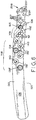
Fig. 1 is a perspective representation of a conventional jig attached to a bone plate; -
Fig. 2 is a top plan view of the jig and bone plate shown inFig. 1 ; -
Fig. 3 is a universal jig in accordance with the present disclosure; -
Fig. 4 is a top plan view of the universal jig shown inFig. 3 ; -
Fig. 5 is a perspective view of the universal jig shown inFig. 3 attached to a PP bone plate and having a masking cover used in cooperation with a short size PP bone plate secured thereto; -
Fig. 6 is a top plan view of the universal jig, bone plate and masking cover shown inFig. 5 ; -
Fig. 7 is a perspective view of the masking cover illustrated inFig. 5 , shown without the bone plate and jig; -
Fig. 8 is a perspective view of the universal jig shown inFig. 3 , illustrating a masking cover used in cooperation with a long size PP bone plate; -
Fig. 9 is a top plan view of the universal jig, bone plate and masking cover shown inFig. 8 ; -
Fig. 10 is a perspective view of the masking cover illustrated inFig. 8 , shown without the bone plate and jig; -
Fig. 11 is a perspective view of the universal jig shown inFig. 3 , illustrating an alternative masking cover used in cooperation with a long size bone plate; -
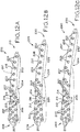
Figs. 12A-12E are top plan views of PP bone plates, illustrating short, medium-short, medium, medium-long and long plates respectively; -
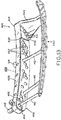
Fig. 13 is a perspective view of another embodiment of a universal jig in accordance with the present disclosure, illustrating a bottom-mounted masking cover; -
Fig. 14 is a perspective view of the universal jig shown inFig. 13 ; -
Figs. 15A-15E are top plan views of bottom-mounted masking covers adapted for use with the PP bone plates shown inFigs. 12A-12E , respectively; -
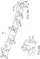
Fig. 16A is a perspective view of another embodiment of a universal jig and masking cover in accordance with the present disclosure; -
Fig. 16B is a partial, perspective view of the universal jig shown inFig. 16A , illustrating indents for attaching the bottom-mounted masking cover; -
Fig. 17 is another perspective view of the universal jig shown inFig. 16A ; -
Fig. 18A is a top plan view of bottom-mounted masking cover shown inFig. 16A ; and -
Fig. 18B is a partial, top plan view of the masking cover shown inFig.18A . - Corresponding reference characters indicate corresponding parts throughout the several views. The exemplifications set out herein illustrate preferred embodiments of the invention and such exemplifications are not to be construed as limiting the scope of the invention in any manner.
- Referring to
Figs. 3 ,13 and16A universal jigs longitudinal bodies fixation arms head portions Bodies upper faces lower faces cannula apertures Cannula apertures body apertures other apertures aperture other aperture Jigs universal jigs universal jigs jig 100 as an exemplar. However, it is to be understood thatjigs jig 100 except as otherwise noted. - Referring now to
Fig. 4 ,apertures 112 may be divided intofirst set 114 adapted to engage both periprosthetic holes ("PP holes") and non-periprosthetic holes ("non-PP holes") depending on plate length, andsecond set 116 adapted to engage only non-PP holes in a long plate length. As seen inFigs. 12A-12E and described in more detail below, PP holes 207 are holes in a periprosthetic zone of a bone plate and are arranged in a pattern that facilitates engagement with a bone/prosthetic combination, while non-PP holes 203 are holes in a non-periprosthetic zone of a bone plate and are arranged in a pattern that facilitates engagement with a bone only. PP holes 207 andnon-PP holes 203 combine to form a variable overall hole pattern on varying lengths of PP bone plates.Jig 100 is adapted to engage each ofholes 203, as well as each of theholes 207 disposed between attachment area 212 (discussed in detail below) and holes 203, regardless of this variable overall pattern. - First set 114 of
apertures 112 includesfirst grouping 114a having threeapertures 112 arranged in a generally oblique orientation with respect tolongitudinal axis 118 ofbody 102. Second, third, fourth and fifth groupings (114b, 114c, 114d and 114e, respectively) are arranged onbody 102 so as to be increasingly distant fromhead portion 106.Groupings 114b, 114c, 114d, 114e each contain a diagonally arranged set of threeapertures 112 similar togrouping 114a, and further include twoadditional apertures 112 flanking the middle hole of the three hole grouping to form an X-shaped pattern similar to the "five side" of a traditional six sided playing die. -
Second set 116 ofapertures 112 includesfirst grouping 116a,second grouping 116b and third grouping 116c, each including two diagonally arrangedapertures 112, with first, second andthird groupings head portion 106 and fromfirst set 114 ofapertures 112.Groupings apertures 112 arranged in a similar fashion to the additional holes added tofirst grouping 114a to create the five-hole groupings 114b-114e. As described in more detail below, these arrangements of hole groupings facilitate the use ofuniversal jig 100 with a variety of bone plates having disparate hole patterns. - Optionally, as shown in
Figs. 13-18B ,universal jigs overhangs Figs. 15a-15e and18A ), as described in detail below.Universal jigs Figs. 14 and17 ) formed inbodies jigs bodies jigs - In the illustrated embodiment,
universal jig 100 is adapted for use in conjunction with a bone plate to repair a fracture on a right-side bone, such as a right femur. However, a mirror image ofjig 100 may be provided to similarly repair a left-side fracture. Moreover, the principles of operation ofjig 100 disclosed herein are applicable to the affixation of a bone plate to any bone. - Periprosthetic bone plates are used for repairing fractures in a bone having an existing or newly implanted prosthesis implanted in the bone. Referring to
Figs. 12A-12E , periprosthetic zones ("PP zone") 206, 226, 246, 266, 286 includePP holes 207 with a pattern adapted to engage a bone/prosthesis combination, whilenon-periprosthetic zones non-PP holes 203 adapted to engage a bone without a prosthesis. While a relatively smaller number ofnon-PP holes 203 may be used for a given length of fractured bone without a prosthesis, a relatively larger number ofPP holes 207 may be used for the same length of bone with a prosthesis implanted therein. Thus, different lengths of a PP bone plates typically have different overall hole patterns. -
Universal jig 100 may be used with PP bone plates including PP zones and non-PP zones, where each zone has a different hole pattern. In the illustrated embodiments,universal jig 100 is adapted to engage five different lengths of PP bone plates, although it is contemplated that the present disclosure may be adapted to engage fewer or more sizes of bone plates as required or desired. Exemplary PP bone plates are shown and described in a U.S. Patent Application entitled A PLATE FOR THE TREATMENT OF BONE FRACTURES (Attorney Docket No. ZIM0793), filed on even date herewith, which claims priority from European Patent Application No.EP09008867.5 filed July 7, 2009 - A variety of plate sizes are shown in
Figs. 12A-12E .Short size plate 200, best seen inFigs. 5 and12A , includesnon-PP zone 202,transition zone 204 andPP zone 206.Non-PP zone 202 includes sixnon-PP holes 203.PP zone 206 includes ten PP holes 207 (Fig. 12A ), as well as jig orientation/registration holes 214 and jig fixation hole 216 (described below). Each ofholes bone contacting surface 217 andfixation surface 218.PP zone 206 terminates athead portion 208 ofplate 200, andtail portion 210 terminates atnon-PP zone 202 ofplate 200.Attachment area 212 is used for the attachment ofuniversal jig 100 toplate 200, as described herein. - Medium-
short size plate 220 similarly includesnon-PP zone 222,transition zone 224 andPP zone 226. Medium-short plate 220 is similar toshort plate 200, except thatPP zone 226 includes three additional PP holes (i.e., one additional set of three holes) 207 extending betweenbone contacting surface 237 andfixation surface 238, as compared toshort plate 200. Accordingly,non-PP zone 222 is located further fromhead portion 228 ofplate 200. However,attachment area 212 remains in the same position onplate 220 with respect tohead portion 228 asattachment area 212 onplate 200.Plate 220 is therefore longer thanplate 200, increasing the distance betweennon-PP zone 222 andattachment area 212. -
Medium size plate 240 similarly includesnon-PP zone 242,transition zone 244 andPP zone 246.PP zone 246 includes three additional PP holes (i.e., one additional set of three holes) 207 extending betweenbone contacting surface 257 andfixation surface 258, as compared with medium-short plate 220. Again,attachment area 212 remains in the same position onplate 240 with respect tohead portion 248 asattachment area 212 onplates Plate 240 is therefore longer thanplate 220 and further distancingnon-PP zone 242 fromattachment area 212. - Medium-
long plate 260 similarly includesnon-PP zone 262,transition zone 264 andPP zone 266.PP zone 266 includes threeadditional PP holes 207 extending betweenbone contacting surface 277 andfixation surface 278, as compared withplate 240. Again,attachment area 212 remains in the same position onplate 260 with respect tohead portion 268 asattachment area 212 onplates Plate 260 is therefore longer thanplate 240, andnon-PP zone 262 is still further distanced fromhead portion 268 as compared withhead portion 248 andnon-PP zone 242 ofplate 240. -
Long plate 280 includesnon-PP zone 282,transition zone 284 andPP zone 286.PP zone 286 includes yet another threeadditional PP holes 207 extending betweenbone contacting surface 297 andfixation surface 298, as compared withplate 260.Attachment area 212 again remains in the same position onplate 280 with respect tohead portion 288 asattachment area 212 onplates Plate 280 is therefore the longest of the five plates illustrated inFigs. 12A-12E , andnon-PP zone 282 is still further distanced fromhead portion 288 as compared withhead portion 268 andnon-PP zone 262 ofplate 260. - Moreover, for all of
plates attachment area 212 remains in the same spatial location with respect torespective head portions additional PP holes 207 disposed betweenattachment area 212 and therespective transition zones attachment area 212 with respect tohead portions non-PP zones attachment area 212. Despite this variance,universal jig 100 is suitable for use with all ofplates - In the illustrated embodiments, no single bone plate utilizes all of
apertures 112 inbody 102 ofuniversal jig 100. Referring generally toFigs. 5-10 , one or more masking covers may be provided to mask offunused cannula apertures 112 for a given length and configuration of bone plate. For example, as shown inFig. 5 , maskingcover 130 may be provided for use withshort plate 200 to mask or coverunused cannula apertures 112 while leaving exposedcannula apertures 112 corresponding to respective holes innon-PP zone 202 andPP zone 206 onplate 200. More particularly, and as shown inFig. 7 , maskingcover 130 includes a plurality ofapertures 132, 132' extending fromlower surface 134 toupper surface 136 of maskingcover 130, withapertures 132, 132' positioned to provide access to only thosecannula apertures 112 used withshort plate 200. - Referring to
Figs. 5-7 and12A , maskingcover 130 includes first set of holes 148 (Figs. 6 and7 ) comprised of apertures 132', which are positioned to make accessible thosecannula apertures 112 inbody 102 ofjig 100 which correspond tonon-PP holes 203 innon-PP zone 202 of short plate 200 (Fig. 12A ). Maskingcover 130 further includes second set of holes 149 (Figs. 6 and7 ) comprised ofapertures 132 adapted to make accessible thosecannula apertures 112 which correspond withPP holes 207 in the portion ofPP zone 206 betweenattachment area 212 andtransition zone 204 of short plate 200 (Fig. 12A ).Apertures 132, 132' are oversized as compared tocannula apertures 112 to accommodate head portion 138' ofstabilization bolt 140 and/orknurled portion 138 of protection sleeve 142 (Figs. 5 and6 ) as described in detail below. - Referring now to
Fig. 7 , maskingcover 130 may further include registration pins 144 which are sized and positioned to engageunused cannula apertures 112 to establish and maintain proper positioning of maskingcover 130 onbody 102 ofjig 100. Registration pins 144 may alternatively be sized and positioned to engage dedicated registration holes 365 (as shown inFig. 3 ). When maskingcover 130 is placed onbody 102 ofjig 100, registration pins 144 fit in to corresponding holes onbody 102 to locate maskingcover 130. If maskingcover 130 is not properly positioned onbody 102, pins 144 will not both fit into corresponding holes onbody 102, thereby providing an indication to the user that maskingcover 130 needs to be repositioned. The holes corresponding topins 144 are unused ones ofcannula apertures 112. Optionally, maskingcover 130 may also include a marking orengraving 146 along a perimeter edge ofcover 130 to identify a particular bone plate associated with maskingcover 130, such asshort plate 200, and whethercover 130 is intended for use on a right or left side anatomical structure. In the illustrated embodiment ofFig. 7 , for example, marking 146 indicates thatplate 130 is designed for use with a right-side jig and a 240 mm bone plate at a distal end of a bone (such as, for example, a femur). - Turning now to
Figs. 8-10 and12E , maskingcover 150 may be provided for use withuniversal jig 100 andlong plate 280. Maskingcover 150 is similar to maskingcover 130, in that it has a plurality ofapertures 152, 152' extending betweenlower surface 154 andupper surface 156 ofcover 150. However,apertures 152, 152' of maskingcover 150 vary in configuration and number as compared withapertures 132, 132' of maskingcover 130.Apertures 152, 152' are, similar toapertures 132, 132', sized to allowknurled portions 138, and/or head portion 138' to pass therethrough. - Masking
cover 150 includes first set ofholes 168 comprising apertures 152' (Figs. 9 and10 ) adapted to make accessible thosecannula apertures 112 inbody 102 ofjig 100 which correspond tonon-PP holes 203 innon-PP zone 282 of long plate 280 (Fig. 12E ). Maskingcover 150 further includes second set ofholes 169 comprising apertures 152 (Figs. 9 and10 ) adapted to make accessible thosecannula apertures 112 which correspond withPP holes 207 in the portion ofPP zone 286 betweenattachment area 212 andtransition zone 284 of long plate 280 (Fig. 12E ). - Similar to masking
cover 130, maskingcover 150 may also include a marking or engraving 166 identifying the corresponding bone plate, such aslong plate 280, by length and/or anatomical side. In the illustrated embodiment ofFig. 10 , for example, marking 166 indicates thatcover 150 is designed for use with a right-side jig and a 400 mm bone plate at a distal end of a bone, such as a femur. At least one registration pin 164 (Fig. 10 ) may also be included in at least one location onlower surface 154 of maskingcover 150 to facilitate positioning and retention of maskingcover 150 onbody 102 ofjig 100, similar toregistration pin 144 of cover 130 (discussed above). - Referring now to
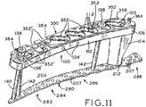
Fig. 11 , analternative masking cover 350 is shown. Maskingcover 350 includesapertures 352, and cutouts 352' extending fromlower surface 354 toupper surface 356.Apertures 352 correspond toPP holes 207 ofplate 280, which are similar toapertures covers non-PP holes 203 ofplate 280, rather than apertures 132', 152' ofcovers cover 350 are not included. - Masking
cover 350 includes registration pins 364 at each end ofcover 350. Similar toregistration pins covers registration holes 365 in body 102 (Figs. 3 and4 ) to orient andsecure cover 350 tobody 102, and to prevent the misalignment ofcover 350 onbody 102. Unlikepins lower surface 354 andupper surface 356, so thatcover 350 is securable to both a right-side jig (such as shown inFig. 11 ) or a left-side jig (which is a mirror image of right-side jig 100, as discussed above) by flippingcover 350 over.Pins 364 may replaceregistration pins covers -
Covers short plate 200 andlong plate 280. However, the principles of operation forcovers short plate 220,medium plate 240, medium-long plate 260, or other periprosthetic bone plates by providing an appropriate number and orientation of respective apertures to correspond with any respective plate. Registration pins 144, 164, 364 may also extend from only one side of their respective masking covers to correspond with either a left-side or right-side jig (as shown inFigs. 7 and 10 with respect topins 144, 164), orregistration pins Fig. 11 with respect to pins 364). - Turning now to
Figs. 13 ,14 , and15a-15e , an alternative embodiment of a universal jig for use with periprosthetic bone plates is shown. Universal fixation device 400 (Figs. 13 and14 ) is substantially similar touniversal fixation device 100, discussed above, with reference numerals ofjig 400 having the same numerals used asjig 100 except with 300 added thereto. Structures ofjig 400 correspond to identical structures denoted by corresponding reference numerals ofjig 100, except as otherwise noted. However,fixation device 400 is specifically adapted to accept bottom-mounted masking covers 411, 420, 430, 440, 450 (Figs. 15a-15e ). More particularly,fixation device 400 includesoverhang 422 disposed betweenlower face 410 andfixation arm 404, such that slot 423 (Fig. 14 ) is formed betweenoverhang 422 andlower face 410. - For purposes of the following description, the interaction between
fixation device 400 and masking covers 411, 420, 430, 440, 450 is described in terms of maskingcover 450, which is shown mounted tofixation device 400 inFig. 13 . However, masking covers 411, 420, 430,440 adapted to leave appropriate cannula holes 412 offixation device 400 exposed for use withplates fixation device 400 in a similar fashion. - Masking
cover 450 includesapertures 452 extending fromlower surface 454 toupper surface 456, similar to masking covers 150, 350 discussed above.Apertures 452 leave certain ones of cannula holes 412 exposed onlower face 410 offixation device 400, while covering certain other cannula holes 412. For long-plate masking cover 450,apertures 452 are positioned to correspond withcannula holes 412 infixation device 400 that are used with long plate 280 (Fig. 13 ). However, unlike masking covers 150, 350 which are adapted to mounted toupper faces 108 ofjig 100, maskingcover 450 is adapted to mount tojig 400 atlower face 410. - Masking
cover 450 includesarcuate end 458 adapted to be received withinslot 423 formed injig 400.Arcuate end 458 includes concave portion 458a and convex portion 458b, which cooperate with a corresponding profile within slot 423 (not shown) to preventend 458 from sliding laterally out ofslot 423 whenend 458 is received therein. Oppositeend 459 of maskingcover 450 is secured tojig 400 by thumbscrew 462 (Fig. 13 ). Specifically,thumbscrew 462 passes through securement aperture 460 (Fig. 15e ) and is threadably received injig body 402. As shown inFigs. 15a-15d , each of masking covers 411, 420, 430, 440, 450 includearcuate end 458 andsecurement aperture 460, such thatslot 423 andthumbscrew 462 may be used to secure any of masking covers 411, 420, 430, 440, 450 tofixation device 400. Whilethumbscrew 462 is shown in the illustrated embodiment for attaching maskingcover 450 tojig body 402, it is contemplated that other methods of fixation may be used, such as clips, set screws or the like. -
Apertures 452 formed in maskingcover 450 may be smaller in diameter as compared toapertures apertures knurled portions 138 and/or head portion 138' ofprotection sleeve 142 andstabilization bolt 140, respectively, to pass therethrough. In contrast,apertures 452 in bottom-mountedmasking cover 450 may be about the same diameter, as cannula holes 412 formed injig body 402. - These "downsized"
apertures 452 allow more material to be retained in the manufacture of maskingcover 450. Maskingcover 450 can be used in lieu of masking covers 150, 350, in thatstabilization bolt 140,protection sleeve 142, and/ordrill guide 143 are prevented from passing throughjig body 402 and into contact withlong plate 280 via any one of cannula holes 412 covered by maskingcover 450. - The three
cannula holes 412 closest tofixation arm 404 and jig body 402 (analogous tofirst grouping 114a formed injig body 102 of Jig 100) are not covered by maskingcovers lower face 410 terminates atslot 423 prior to reachingfixation arm 404, as shown inFig. 13 . However, all sizes ofexemplary bone plates cannula holes 412, and therefore these threecannula holes 412 need not be covered to prevent passage ofstabilization bolt 140,protection sleeve 142 and/ordrill guide 143 therethrough. - Turning now to
Figs. 16A-18B , yet another alternative embodiment of the universal jig is shown.Universal jig 500 is similar tojig 400 described above, in that maskingcover 550 mounts tolower face 510 ofjig body 502. Moreover,jig 500 is similar tojig 400 described above, with reference numerals ofjig 500 having the same numerals used asjig 400 except with 100 added thereto. Structures ofjig 500 correspond to identical structures denoted by corresponding reference numerals ofjig 400, except as otherwise noted. - Rather than
overhang 422 formingslot 423 as described above with respect tojig 400,overhang 522 of jig 500 (Fig. 16A ) extends the entire length ofjig body 502 to formslot 523. Slot 523 also extends transversely across the width ofjig body 502 at both ends, and includes a pair of indents 562 (Fig. 16B ) sized and positioned to receiveprotuberances 560 formed in respective ends of cover 550 (as described in detail below).Indents 562 are formed by drilling small holes injig body 502 such that the drill bit creates a semi-circular void in the inner wall ofslot 523. For illustration purposes, only cover 550 adapted for use with longestPP bone plate 280 is shown. Other masking covers adapted for use withjig 500 may be provided in conjunction with other bone plate sizes, as described above with respect tojigs - In use, masking
cover 550 is assembled tojig 500 by slidingcover 550 laterally acrosslower face 510 and intoslot 523 until each one ofprotuberances 560 are fully seated in arespective indent 562. In order to facilitate such seating,openings 564 are formed in maskingcover 550 nearprotuberances 560. Whenprotuberances 560 are urged backward upon engagement withslot 523, the relatively thin material betweenopenings 564 andprotuberances 560 deflects. Whenprotuberances 560 align withindents 562, the material resiliently "snaps"protuberances 560 intoindents 562 to secure maskingcover 550 tojig body 502. Thus, no additional fixation (i.e. a thumbscrew or other mechanical attachment) is needed to secure maskingcover 550 tojig body 502. In an exemplary embodiment, bothjig body 502 and maskingcover 550 are made of a resilient polymer, such as Radel® (Radel® is a registered trademark of Solvay Advanced Polymers LLC of Alpharetta, Georgia) or Ultem® (Ultem® is a registered trademark of Sabic Innovative Plastics Co. of The Netherlands). -
Jig body 500 may includesrecesses 570 for enhanced grip, i.e., by a surgeon during use.Jig 500 further includesfixation arm reinforcement 504a attached at the end offixation arm 504, which is made of a rigid metallic material and provides a long-wearing interface between fixation arm 504 (which may be made of a relatively softer material, such as PEEK described above) andattachment area 212 ofbone plates Figs. 12A-12E ).Reinforcement 504a is secured tofixation arm 504 by adhesive and/or by pins (not shown) passing throughpin holes 504b and into the material offixation arm 504. -
Jig 500 may include K-wire guides 503, similar toguides 403 formed injig 400. However, as best seen inFig. 17 , an additional set of K-wire guides 503 are also formed within the outer profile of jig body 502 (as opposed to inprotrusions 505 extending outwardly therefrom). Optionally, the inner set of K-wire guides 503 formed in the main portion ofjig body 502 may obviate the need forguides 503 formed inprotrusions 505, such thatprotrusions 505 may be left off for ease ofmanufacturing jig 500. - In use,
universal jig 100 allows for the percutaneous implantation of fasteners to fasten various sizes of periprosthetic bone plates to a bone, thereby allowing for smaller incisions consistent with goals of MIS techniques. By way of illustration, the use ofjig 100 will be described with respect toshort plate 200, as shown inFigs. 5-7 and12A . Similar methodology is used for other bone plates of different lengths, such as withlong plate 280 as shown inFigs. 8 and 9 .Jig 100 may also be used in conjunction with PP bone plates for a variety of anatomical structures, and in proximal or distal fractures. By providing a right-side jig (such as jig 100) and left-side jig (a mirror image ofjig 100, as discussed above), a universal jig in accordance with the present disclosure is also useable in both left- and right-side applications. -
Jig 100 may be used with short sizedPP bone plate 200 as shown inFigs. 5 and6 .Fixation arm 104 ofjig 100 is first attached to shortsize bone plate 200 at attachment area 212 (Fig. 12A ). To facilitate and maintain an accurate orientation of jig relative tobone plate 200,fixation arm 104 includes two jig registration pins (not shown) sized and positioned to correspond withorientation holes 214 inattachment area 212. Attachment aperture 120 (Figs. 3 and4 ) is provided inhead portion 106 ofbody 102 and extends throughfixation arm 104 to provide a path for arm fastener 105 (Figs. 5 and6 ) to pass throughbody 102 andfixation arm 104 and to engage threadedfixation hole 216 inattachment area 212 ofplate 200. - With
jig 100 attached to plate 200 viafixation arm 104, a small incision is made near an end of a fractured bone.Plate 200 is then inserted through the incision, leading withtail portion 210, and into contact the fractured bone. Whenplate 200 is inserted so thathead portion 208 is near the end of the fractured bone and withplate 200 spanning the fracture,jig 100 is used to attachplate 200 to the fractured bone. More particularly,stabilization bolt 140 is used to securetail portion 210 ofplate 200 tojig 100, as well as to ensure proper spacing betweenjig 100 andbone plate 200.Stabilization bolt 140 also provides a path for passage of a fastening element to attachtail portion 210 to a bone, as described below. - Optionally, prior to securement of the jig with
stabilization bolt 140, one ofjigs 400, 500 (Figs. 14 and17 ) having K-wire guides 403, 503 may be used in conjunction with K-wires or other guide wires to secure one ofjig bodies plates body jigs stabilization bolt 140 can then be used for initial fixation of a respective one ofplates - An
appropriate aperture 112 is selected for threaded attachment of stabilization bolt 140 (Fig. 5 ) tojig 100 at thenon-PP hole 203 closest to the end oftail portion 210 ofplate 200. Masking cover 130 (or a corresponding bottom-mounted masking cover, such as cover 430) may optionally be utilized to mask offunused apertures 112 forshort size plate 200, as described in detail above, in which case the aperture 132' farthest fromhead portion 106 corresponds to hole 203 for use withstabilization bolt 140. However, appropriate ones ofapertures 112 corresponding withholes cover 130. - With the
proper aperture 112 selected for use withstabilization bolt 140, a stab incision is made through the selectedcannula aperture 112.Stabilization bolt 140 is advanced through the incision and threaded intonon-PP hole 203 to securejig 100 totail portion 210 of plate 200 (Fig. 5 ). Once threaded intohole 203,body 102 ofjig 100 may be adjusted along the axis ofbolt 140 to bring head portion 138' ofstabilization bolt 140 into contact withupper face 108 ofbody 102. While maintaining such contact, a lock pin (not shown) is inserted intobody 102 to ensure the proper distance is maintained. - Referring now to
Fig. 3 ,transverse holes 124 are provided injig 100 to facilitate securement ofstabilization bolt 140 tobody 102.Stabilization bolt 140 includes a groove (not shown) which intersects with one oftransverse holes 124 whenbolt 140 is received withincannula aperture 112. A lock pin (not shown) may be passed into a respectivetransverse hole 124 to engage the groove onstabilization bolt 140, thereby securingstabilization bolt 140 tobody 102 ofjig 100. As shown inFig. 3 , fivetransverse holes 124 are provided inbody 102 to correspond with the position ofstabilization bolt 140 for each of the five lengths of bone plates 200,220,240,260,280. - Referring generally to
Fig. 5 ,head portion 208 is then secured to the bone via PP holes 207 using any suitable methods and fasteners (not shown). Withhead portion 208 secured, a wire (not shown) inserted throughstabilization bolt 140 may be used to securetail portion 210 ofplate 200 to the fractured bone. A second stab incision is then made through a chosen one of the remainingavailable cannula apertures 112 inbody 102.Protection sleeve 142 is then inserted through the chosenaperture 112 so that it extends into the second stab incision at the proper location and with the proper trajectory toward thecorresponding hole plate 200.Protection sleeve 142 may include adrill guide 143 received therein, which is then threaded into the threaded hole of the bone plate. A trocar (not shown) may also be included to aid in passage ofprotection sleeve 142 through the second stab incision. - With
protection sleeve 142proximate plate 200 and a respective one ofholes protection sleeve 142 is screwed intocannula aperture 112 ofbody 102 ofjig 100 so thatprotection sleeve 142 comes into contact withplate 200.Drill guide 143 may then be used to drill a pilot hole for a fastener, and may subsequently be removed fromprotection sleeve 142 to allow a fastener to be passed therethrough and to fastenplate 200 to the bone. This procedure may be repeated inother cannula apertures 112 ofjig 100 as desired or required for a particular surgical procedure, untilplate 200 is satisfactorily secured to the bone. Any remainingprotection sleeves 142 may then be removed.Universal jig 100 may then be disconnected fromplate 200 by removingstabilization bolt 140 andfixation arm fastener 105 frombody 102 andfixation arm 104, respectively. -
Cannula apertures 112 ofjig 100 correspond to bothPP holes 207 andnon-PP holes 203 inPP zone 206 andnon-PP zone 202, respectively. Thus,jig 100 may be used to secureplate 200 to a part of a bone with no existing prosthesis by using selectedcannula apertures 112 corresponding withnon-PP zone 202, and may also be used to secureplate 200 to a part of a bone with an existing prosthesis implanted in the bone by using selectedcannula apertures 112 corresponding withPP zone 206. -
Universal jig 100 may be used with a variety of PP plates having different lengths, such asPP plates Figs. 12A-12E , respectively. The multiple holes found in first set ofholes 114 and second set ofholes 116 inbody 102 allowuniversal jig 100 to engage bothnon-PP holes 203 andPP holes 207 in any of a variety of plate lengths, while still allowingfixation arm 104 ofjig 100 to attach to anattachment area 212 so thathead portion 208 of each plate has a consistent spatial relationship withuniversal jig 100 regardless of plate length. Put another way,universal jig 100 obviates the need for separate jigs for each plate length, despite variation in the distance betweenattachment area 212 andnon-PP zones - Further, the configuration of
body 102 ofuniversal jig 100 allowscannula apertures 112 to be distinct one from the other, thereby preventing any overlap of the areas ofcannula apertures 112. Preventing such overlap maintains material contact betweenbody 102 andstabilization bolt 140 and/orprotection sleeves 142, thereby ensuring a rigid and accurate connection therebetween for allcannula apertures 112. However,cannula apertures 112 may be considered to be "distinct" within the scope of the present disclosure even where there is some amount of "overlap" between neighboringcannula apertures 112, provided the overlappingcannula apertures 112 adequately secure and orient protection sleeves 142 (or another structure contained by a cannula aperture 112). - The optional inclusion of masking covers 150, 350, 450, 550, as well as similarly constructed masking covers for intermediate plate sizes, promotes ease of use of
universal jigs only cannula apertures universal jigs - Still further,
universal jigs head portion 208 is shown in the illustrated embodiments, the head portion of any length of PP bone plate may be altered without affecting the usability ofjigs jigs attachment area 212 viafixation arm 104, the portion ofplate attachment area 212 andhead portion 208 may be altered as required or desired for a particular application without affecting the interaction betweenjigs - While this invention has been described as having an exemplary design, the present invention can be further modified within the spirit and scope of this disclosure. This application is therefore intended to cover any variations, uses, or adaptations of the invention using its general principles. Further, this application is intended to cover such departures from the present disclosure as come within known or customary practice in the art to which this invention pertains and which fall within the limits of the appended claims.
Claims (35)
- A bone plate fixation system, comprising:a first bone plate having a plurality of first bone plate holes arranged in a first bone plate hole configuration, the first bone plate hole configuration including a portion of the plurality of first bone plate holes arranged in a periprosthetic zone and a portion of the plurality of first bone plate holes arranged in a non-periprosthetic zone;a second bone plate having a plurality of second bone plate holes arranged in a second bone plate hole configuration, the second bone plate hole configuration including a portion of the plurality of second bone plate holes arranged in a periprosthetic zone and a portion of the plurality of second bone plate holes arranged in a non-periprosthetic zone; anda jig having a jig body, the jig body includinga first set of apertures, at least a portion of the first set of apertures configured to align with the periprosthetic zone of the first bone plate, and at least a portion of the first set of apertures configured to align with the periprosthetic zone of the second bone plate; anda second set of apertures, at least a portion of the second set of apertures being configured to align with the non-prosthetic zone of the second bone plate;wherein the first bone plate hole configuration is different from the second bone plate hole configuration.
- A bone plate fixation system of claim 1, wherein the portion of the first set of apertures configured to align with the periprosthetic zone of the first bone plate includes less apertures than the portion of the second set of apertures configured to align with the periprosthetic zone of the second bone plate.
- The bone plate fixation system of claim 1, wherein a portion of the first set of apertures is further configured to align with a portion of the non-periprosthetic zone of the first bone plate.
- The bone plate fixation system of claim 1, wherein the first set of apertures includes at least one grouping having at least three apertures positioned diagonally, in a first direction, across the jig body.
- The bone plate fixation system of claim 1, wherein a number of holes in the first bone plate non-periprosthetic zone is less than a number of holes in the second bone plate non-periprosthetic zone.
- The bone plate fixation system of claim 1, wherein the second set of apertures includes at least one grouping having at least two apertures positioned diagonally, in a second direction, across the jig body.
- The bone plate fixation system of claim 1, wherein a number of holes in the first bone plate periprosthetic zone equals a number of holes in the second bone plate periprosthetic zone.
- The bone plate fixation system of claim 1, wherein the jig body further includes a fixation arm extending from the jig body, the fixation arm attachable to the first bone plate and the second bone plate bone plate.
- The bone plate fixation system of claim 1, further including:a first masking cover configured to mount to the jig body, the first masking cover including a plurality of first masking cover apertures having a first masking cover configuration substantially matching the first bone plate hole configuration.
- The bone plate fixation system of claim 9, wherein the first masking cover is configured to cover the portions of the first and second sets of apertures in the jig body that correspond solely to the second bone plate hole configuration.
- The bone plate fixation system of claim 9, further including:a second masking cover configured to mount to the jig body, the second masking cover including a plurality of second masking cover apertures having a second masking cover configuration substantially matching the second bone plate hole configuration.
- The bone plate fixation system of claim 11, wherein the second masking cover is configured to cover the portions of the first and second sets of apertures in the jig body that correspond solely to the first bone plate hole configuration.
- The bone plate fixation system of claim 1, wherein the first set of apertures include a plurality of first groupings of apertures, each of the first groupings of apertures including three apertures positioned diagonally, in a first direction, across the jig body, wherein at least one of the first groupings of apertures includes two apertures flanking a middle aperture of the three apertures; and the second set of apertures, positioned adjacent to the first set of apertures, include at least one second grouping of apertures, the second grouping of apertures including two apertures positioned diagonally, in a second direction, across the jig body.
- The bone plate fixation system of claim 14, wherein a first portion of the first set of apertures corresponds to at least a portion of the first bone plate hole configuration and a second portion of the first set of apertures corresponds to at least a portion of the second bone plate hole configuration, the first portion and the second portion including a different number of apertures.
- The bone plate fixation system of claim 14, wherein at least one aperture of the first set of apertures in the jig body corresponds to both a first bone plate hole and a second bone plate hole.
- A bone plate fixation system comprising:a first bone plate comprising a first bone plate body having a first bone plate longitudinal extent, said first bone plate body including a plurality of holes disposed along a portion of said first bone plate longitudinal extent and arranged in a first bone plate hole configuration;a second bone plate comprising a second bone plate body having a second bone plate longitudinal extent, said second bone plate body including a plurality of second bone plate holes disposed along a portion of said second bone plate longitudinal extent and arranged in a second bone plate hole configuration, said portion of said second bone plate longitudinal extent along which said second bone plate holes are disposed having a length approximately equal to said portion of said first bone plate longitudinal extent along which said first bone plate holes are disposed, said second bone plate hole configuration different from said first bone plate hole configuration; anda jig comprising:a jig body having a jig body longitudinal extent, said jig body including a plurality of cannula apertures, at least a portion of said plurality of cannula apertures arranged along a portion of said jig body longitudinal extent to correspond to said first bone plate hole configuration, at least a portion of said plurality of cannula apertures arranged along said portion of said jig body longitudinal extent to correspond to said second bone plate hole configuration, wherein said first bone plate hole configuration and said second bone plate hole configuration are each arranged along a common length of said jig body; anda fixation arm extending from said jig body, said fixation arm attachable to said first bone plate and said second bone plate.
- The bone plate fixation system of claim 16, wherein said first bone plate hole configuration and said second bone plate hole configuration each comprise a periprosthetic zone and a non-periprosthetic zone.
- The bone plate fixation system of claim 16, further comprising:a first masking cover adapted to mount to said jig and cooperate with said first bone plate, said first masking cover comprising:a first masking cover upper surface and a first masking cover lower surface; anda plurality of first masking cover apertures extending between said first masking cover upper surface and said first masking cover lower surface, said first masking cover apertures positioned to identify a subset of said plurality of cannula apertures corresponding to said plurality of first bone plate holes.
- The bone plate fixation system of claim 18, wherein said first masking cover further comprises at least one first masking cover registration pin adapted to cooperate with said jig, said first masking cover registration pin operable to restrain movement of said first masking cover relative to said jig when said first masking cover is mounted to said jig.
- The bone plate fixation system of claim 18, further comprising:a second masking cover adapted to mount to said jig and cooperate with said second bone plate, said second masking cover comprising:a second masking cover upper surface and a second masking cover lower surface; anda plurality of second masking cover apertures extending between said second masking cover upper surface and said second masking cover lower surface, said second masking cover apertures positioned to identify a subset of said plurality of cannula apertures corresponding to said plurality of second bone plate holes.
- The bone plate fixation system of claim 20, wherein said second masking cover further comprises at least one second masking cover registration pin adapted to cooperate with said jig, said second masking cover registration pin operable to restrain movement of said second masking cover with respect to said jig when said second masking cover is mounted to said jig.
- The bone plate fixation system of claim 18, wherein said plurality of cannula apertures extend from a lower face of said jig body to an upper face of said jig body, and said first masking cover mounts to at least one of said lower face and said upper face.
- A bone plate fixation system comprising:a first bone plate having a first bone plate set of holes;a jig comprising:a jig body including a plurality of cannula apertures, at least a portion of said plurality of cannula apertures positioned so that each said hole of said first bone plate set of holes corresponds with a respective one of said plurality of cannula apertures; anda fixation arm extending away from said jig body, said fixation arm adapted to attach said jig to said first bone plate; anda first masking cover cooperating with said jig to expose each of said plurality of cannula apertures corresponding to said first bone plate set of holes, said first masking cover covering each of said plurality of cannula apertures not corresponding to said first bone plate set of holes.
- The bone plate fixation system of claim 23, wherein said plurality of cannula apertures extend from a lower face of said jig body to an upper face of said jig body, and said first masking cover mounts to at least one of said lower face and said upper face.
- The bone plate fixation system of claim 23, wherein said first bone plate set of holes comprises:a first non-periprosthetic hole pattern adapted to attach to a bone; anda first periprosthetic hole pattern adapted to attach to a portion of the bone having a prosthesis implanted therein.
- The bone plate fixation system of claim 23, further comprising:a second bone plate having a second bone plate set of holes having a configuration that is different from said first bone plate set of holes;a second masking cover cooperating with said jig to expose each of said plurality of cannula apertures corresponding to said second bone plate set of holes, said second masking cover covering each of said plurality of cannula apertures not corresponding to said second bone plate set of holes.
- The bone plate fixation system of claim 23, wherein said first masking cover further comprises at least one first masking cover registration pin adapted to cooperate with said jig, said first masking cover registration pin operable to restrain movement of said first masking cover with respect to said jig when said first masking cover is mounted to said jig.
- The bone plate fixation system of claim 27, wherein said first masking cover includes a first masking cover lower surface, said first masking cover registration pin extending from said first masking cover lower surface into said jig body when said first masking cover lower surface is mounted to said jig.
- The bone plate fixation system of claim 27, wherein said first masking cover includes a first masking cover lower surface and a first masking cover upper surface, said first masking cover registration pin extending from said first masking cover lower surface and from said-first masking cover upper surface, so that aid first masking cover registration pin extends into said jig body when one of said first masking cover upper surface and said first masking cover lower surface are mounted to said jig.
- A bone plate fixation system comprising:a first bone plate comprising a first bone plate body having a first bone plate plurality of holes arranged in a first bone plate hole configuration;a jig comprising:a jig body including a plurality of cannula apertures, at least a portion of said plurality of cannula apertures positioned so that each hole of said first bone plate plurality of holes corresponds with a respective one of said plurality of cannula apertures; anda fixation arm extending away from said jig body, said fixation arm adapted to attach said jig to said first bone plate; andmeans for identifying a subset of said plurality of cannula apertures corresponding to said first bone plate plurality of holes.
- The bone plate fixation system of claim 30, wherein said first bone plate hole configuration comprises a first bone plate periprosthetic zone and a first bone plate non-periprosthetic zone.
- The bone plate fixation system of claim 30, further comprising:a second bone plate comprising a second bone plate body having a second bone plate plurality of holes arranged in a second bone plate hole configuration, said second bone plate hole configuration different from said first bone plate hole configuration;means for identifying a subset of said plurality of cannula apertures corresponding to said second bone plate plurality of holes.
- The bone plate fixation system of claim 32, wherein said second bone plate hole configuration comprises a second bone plate periprosthetic zone and a second bone plate non-periprosthetic zone.
- The bone plate fixation system of claim 30, wherein said means for identifying comprises a means for selectively covering at least a portion of each of said first bone plate plurality of holes.
- The bone plate fixation system of claim 34, wherein said plurality of cannula apertures in said jig body extend from an upper surface of said jig body to a lower surface of said jig body, said means for identifying comprising :a cover, said cover mountable to at least one of said upper surface of said jig body and said lower surface of said jig body; andmeans for orienting said cover on said body of said jig.
Applications Claiming Priority (3)
| Application Number | Priority Date | Filing Date | Title |
|---|---|---|---|
| US12/683,953 US8328809B2 (en) | 2010-01-07 | 2010-01-07 | Bone plate fixation system |
| PCT/EP2011/000038 WO2011083084A1 (en) | 2010-01-07 | 2011-01-07 | Bone plate fixation system |
| EP11700791.4A EP2521496B1 (en) | 2010-01-07 | 2011-01-07 | Bone plate fixation system |
Related Parent Applications (1)
| Application Number | Title | Priority Date | Filing Date |
|---|---|---|---|
| EP11700791.4A Division EP2521496B1 (en) | 2010-01-07 | 2011-01-07 | Bone plate fixation system |
Publications (2)
| Publication Number | Publication Date |
|---|---|
| EP3263051A1 true EP3263051A1 (en) | 2018-01-03 |
| EP3263051B1 EP3263051B1 (en) | 2019-10-02 |
Family
ID=43838163
Family Applications (2)
| Application Number | Title | Priority Date | Filing Date |
|---|---|---|---|
| EP17159750.3A Active EP3263051B1 (en) | 2010-01-07 | 2011-01-07 | Bone plate fixation system |
| EP11700791.4A Active EP2521496B1 (en) | 2010-01-07 | 2011-01-07 | Bone plate fixation system |
Family Applications After (1)
| Application Number | Title | Priority Date | Filing Date |
|---|---|---|---|
| EP11700791.4A Active EP2521496B1 (en) | 2010-01-07 | 2011-01-07 | Bone plate fixation system |
Country Status (3)
| Country | Link |
|---|---|
| US (2) | US8328809B2 (en) |
| EP (2) | EP3263051B1 (en) |
| WO (1) | WO2011083084A1 (en) |
Families Citing this family (30)
| Publication number | Priority date | Publication date | Assignee | Title |
|---|---|---|---|---|
| US8328809B2 (en) | 2010-01-07 | 2012-12-11 | Zimmer, Inc. | Bone plate fixation system |
| US9161796B2 (en) * | 2010-12-18 | 2015-10-20 | The Brigham And Women's Hospital, Inc. | Medical devices for use during ankle fusion surgery |
| US9861402B2 (en) * | 2012-03-08 | 2018-01-09 | Trimed, Incorporated | System and method for treating a fractured bone |
| TW201412283A (en) * | 2012-09-17 | 2014-04-01 | Metal Ind Res & Dev Ct | Guiding device for bone fixation surgery |
| CN102961179A (en) * | 2012-12-03 | 2013-03-13 | 浙江科惠医疗器械有限公司 | Universal locking and pressurizing bone plate |
| US9138245B2 (en) * | 2013-02-27 | 2015-09-22 | Biomet C.V. | Jig with guide adapted to lock relative to both of threaded holes and non-threaded slots in a bone plate |
| US9289247B2 (en) * | 2013-03-15 | 2016-03-22 | Kyphon SÀRL | Surgical tool holder |
| US10610368B2 (en) | 2018-05-26 | 2020-04-07 | Acumed Llc | Ankle fusion system with expandable spacer |
| EP3164092B1 (en) * | 2014-07-02 | 2023-09-06 | Paragon 28, Inc. | Moveable bone plate implantation system |
| AU2014405942B2 (en) * | 2014-09-12 | 2019-05-16 | Innovision, Inc. | Bone drill guides and methods of use thereof |
| CN105816236A (en) * | 2015-01-06 | 2016-08-03 | 上海微创骨科医疗科技有限公司 | Medical guide device and guide system |
| DE102015121487A1 (en) * | 2015-12-10 | 2017-06-14 | Aesculap Ag | Surgical instrument, surgical system and method of making a surgical instrument |
| US10856919B2 (en) * | 2016-02-22 | 2020-12-08 | Life Spine, Inc. | Lateral spine plate with set screw locking of bone screws |
| US10368928B2 (en) * | 2017-03-13 | 2019-08-06 | Globus Medical, Inc. | Bone stabilization systems |
| US11344344B2 (en) * | 2017-03-13 | 2022-05-31 | DePuy Synthes Products, Inc. | Proximal femur hook plate |
| US11033333B2 (en) | 2017-04-06 | 2021-06-15 | Stryker European Holdings I, Llc | Plate selection user interface and design tool with database |
| EP3424452B1 (en) | 2017-06-16 | 2024-03-13 | Stryker European Operations Holdings LLC | Patient-specific bridging plates |
| EP3782567A1 (en) * | 2017-08-14 | 2021-02-24 | Stryker European Holdings I, LLC | Femur plate |
| US11096730B2 (en) * | 2017-09-13 | 2021-08-24 | Globus Medical Inc. | Bone stabilization systems |
| US12279795B2 (en) * | 2017-09-13 | 2025-04-22 | Globus Medical, Inc. | Bone stabilization systems |
| DE102017121242A1 (en) * | 2017-09-13 | 2019-03-14 | Ot Medizintechnik Gmbh | Positioning device for fixing a polyaxial plate to a tubular bone by means of a hole section |
| US10856920B2 (en) | 2017-09-13 | 2020-12-08 | Globus Medical Inc. | Bone stabilization systems |
| US10849665B2 (en) | 2018-10-29 | 2020-12-01 | Stryker European Operations Holdings Llc | Snap-fit cutting guides and plating systems |
| GB2584658B (en) | 2019-06-07 | 2022-02-23 | Usw Commercial Services Ltd | Support for an anatomical structure |
| US11389209B2 (en) * | 2019-07-19 | 2022-07-19 | Medos International Sarl | Surgical plating systems, devices, and related methods |
| EP4051144B1 (en) | 2019-10-29 | 2025-08-13 | Smith & Nephew, Inc. | Periprosthetic bone plate systems |
| US12357358B2 (en) | 2020-05-19 | 2025-07-15 | Smith & Nephew, Inc. | Periprosthetic bone plate |
| WO2022086455A1 (en) * | 2020-10-21 | 2022-04-28 | Meticuly Company Limited | Bone fixation system for human bone, method of designing and manufacturing thereof |
| US11432832B2 (en) | 2020-12-03 | 2022-09-06 | Stryker European Operations Limited | Minimally invasive surgery targeting guides and methods of use |
| EP4291114A1 (en) * | 2021-02-11 | 2023-12-20 | Smith & Nephew, Inc. | A targeting system for a periprosthetic bone plate |
Citations (5)
| Publication number | Priority date | Publication date | Assignee | Title |
|---|---|---|---|---|
| US20050049594A1 (en) * | 2001-04-20 | 2005-03-03 | Wack Michael A. | Dual locking plate and associated method |
| US20060095044A1 (en) * | 2004-11-03 | 2006-05-04 | Grady Mark P Jr | Aiming arm for bone plates |
| US20070173843A1 (en) * | 2005-12-22 | 2007-07-26 | Matityahu Amir M | Drug delivering bone plate and method and targeting device for use therewith |
| WO2009042510A2 (en) * | 2007-09-27 | 2009-04-02 | Depuy Products, Inc | Apparatus and methods associated with a hip fracture reduction procedure |
| US20090312760A1 (en) * | 2004-10-07 | 2009-12-17 | Zimmer, Inc. | Bone fracture fixation system |
Family Cites Families (13)
| Publication number | Priority date | Publication date | Assignee | Title |
|---|---|---|---|---|
| ZA80327B (en) * | 1979-08-23 | 1981-09-30 | U Mennen | Internal fixation device for bone fractures |
| US5976139A (en) | 1996-07-17 | 1999-11-02 | Bramlet; Dale G. | Surgical fastener assembly |
| US6706046B2 (en) * | 2000-02-01 | 2004-03-16 | Hand Innovations, Inc. | Intramedullary fixation device for metaphyseal long bone fractures and methods of using the same |
| USD480141S1 (en) | 2000-06-01 | 2003-09-30 | Steve Benirschke | Bone plate |
| USD469874S1 (en) | 2002-04-26 | 2003-02-04 | Zimmer, Inc. | Orthopaedic bone plate |
| USD469875S1 (en) | 2002-04-26 | 2003-02-04 | Zimmer, Inc. | Orthopaedic bone plate |
| USD470588S1 (en) | 2002-04-26 | 2003-02-18 | Zimmer, Inc. | Orthopaedic bone plate |
| US7229445B2 (en) | 2004-06-21 | 2007-06-12 | Synthes (Usa) | Bone plate with bladed portion |
| US20080183172A1 (en) | 2007-01-26 | 2008-07-31 | Zimmer Technology, Inc. | Retention feature for plate guides |
| USD642685S1 (en) | 2010-01-07 | 2011-08-02 | Zimmer Gmbh | Bone plate fixation device |
| US8328809B2 (en) | 2010-01-07 | 2012-12-11 | Zimmer, Inc. | Bone plate fixation system |
| USD638942S1 (en) | 2010-01-07 | 2011-05-31 | Zimmer, Inc. | Bone plate fixation device |
| USD655010S1 (en) | 2011-03-25 | 2012-02-28 | Zimmer, Inc. | Bone plate fixation device |
-
2010
- 2010-01-07 US US12/683,953 patent/US8328809B2/en active Active
-
2011
- 2011-01-07 EP EP17159750.3A patent/EP3263051B1/en active Active
- 2011-01-07 WO PCT/EP2011/000038 patent/WO2011083084A1/en not_active Ceased
- 2011-01-07 EP EP11700791.4A patent/EP2521496B1/en active Active
-
2012
- 2012-12-10 US US13/709,722 patent/US9155575B2/en active Active
Patent Citations (5)
| Publication number | Priority date | Publication date | Assignee | Title |
|---|---|---|---|---|
| US20050049594A1 (en) * | 2001-04-20 | 2005-03-03 | Wack Michael A. | Dual locking plate and associated method |
| US20090312760A1 (en) * | 2004-10-07 | 2009-12-17 | Zimmer, Inc. | Bone fracture fixation system |
| US20060095044A1 (en) * | 2004-11-03 | 2006-05-04 | Grady Mark P Jr | Aiming arm for bone plates |
| US20070173843A1 (en) * | 2005-12-22 | 2007-07-26 | Matityahu Amir M | Drug delivering bone plate and method and targeting device for use therewith |
| WO2009042510A2 (en) * | 2007-09-27 | 2009-04-02 | Depuy Products, Inc | Apparatus and methods associated with a hip fracture reduction procedure |
Non-Patent Citations (1)
| Title |
|---|
| ANONYMOUS: "NCB Distal Femoral Plating System Surgical Technique", 2008, ZIMMER INC., Warsaw, Indiana, US, pages: 1 - 25, XP002775169 * |
Also Published As
| Publication number | Publication date |
|---|---|
| US9155575B2 (en) | 2015-10-13 |
| WO2011083084A1 (en) | 2011-07-14 |
| EP3263051B1 (en) | 2019-10-02 |
| US20110166573A1 (en) | 2011-07-07 |
| EP2521496B1 (en) | 2017-03-08 |
| EP2521496A1 (en) | 2012-11-14 |
| US8328809B2 (en) | 2012-12-11 |
| US20130096560A1 (en) | 2013-04-18 |
Similar Documents
| Publication | Publication Date | Title |
|---|---|---|
| EP3263051B1 (en) | Bone plate fixation system | |
| US12089883B2 (en) | Bone stabilization systems | |
| JP7134651B2 (en) | bone stabilization system | |
| US9320554B2 (en) | Wrist fusion plate | |
| US8192449B2 (en) | Non-penetrating fixing device | |
| EP2906129B1 (en) | Bone shortening device | |
| EP1764053B1 (en) | Bone fixation plate with complex suture anchor locations | |
| US7153309B2 (en) | Guide system for bone-repair devices | |
| US20100262193A1 (en) | Osseosynthesis Plate with Keyhole Feature | |
| US11839556B2 (en) | Bone plate trial | |
| CA2973589A1 (en) | Washer plate | |
| US20120022534A1 (en) | Intramedullary arthrodesis nail and method of use | |
| US20120016366A1 (en) | Proximal Radius Locking Plate | |
| US11617609B2 (en) | Percutaneous methods, systems, and devices for positioning a guide wire in a bone | |
| EP4534025A1 (en) | Template for fracture reduction and positioning of plates in osteosynthesis | |
| US10646695B1 (en) | Percutaneous methods, systems, and devices for positioning a guide wire in a bone |
Legal Events
| Date | Code | Title | Description |
|---|---|---|---|
| PUAI | Public reference made under article 153(3) epc to a published international application that has entered the european phase |
Free format text: ORIGINAL CODE: 0009012 |
|
| STAA | Information on the status of an ep patent application or granted ep patent |
Free format text: STATUS: THE APPLICATION HAS BEEN PUBLISHED |
|
| AC | Divisional application: reference to earlier application |
Ref document number: 2521496 Country of ref document: EP Kind code of ref document: P |
|
| AK | Designated contracting states |
Kind code of ref document: A1 Designated state(s): AL AT BE BG CH CY CZ DE DK EE ES FI FR GB GR HR HU IE IS IT LI LT LU LV MC MK MT NL NO PL PT RO RS SE SI SK SM TR |
|
| STAA | Information on the status of an ep patent application or granted ep patent |
Free format text: STATUS: REQUEST FOR EXAMINATION WAS MADE |
|
| 17P | Request for examination filed |
Effective date: 20180703 |
|
| RBV | Designated contracting states (corrected) |
Designated state(s): AL AT BE BG CH CY CZ DE DK EE ES FI FR GB GR HR HU IE IS IT LI LT LU LV MC MK MT NL NO PL PT RO RS SE SI SK SM TR |
|
| REG | Reference to a national code |
Ref country code: DE Ref legal event code: R079 Ref document number: 602011062540 Country of ref document: DE Free format text: PREVIOUS MAIN CLASS: A61B0017170000 Ipc: A61B0017800000 |
|
| GRAP | Despatch of communication of intention to grant a patent |
Free format text: ORIGINAL CODE: EPIDOSNIGR1 |
|
| STAA | Information on the status of an ep patent application or granted ep patent |
Free format text: STATUS: GRANT OF PATENT IS INTENDED |
|
| RIC1 | Information provided on ipc code assigned before grant |
Ipc: A61B 17/80 20060101AFI20190312BHEP Ipc: A61B 17/17 20060101ALI20190312BHEP |
|
| INTG | Intention to grant announced |
Effective date: 20190410 |
|
| GRAS | Grant fee paid |
Free format text: ORIGINAL CODE: EPIDOSNIGR3 |
|
| GRAA | (expected) grant |
Free format text: ORIGINAL CODE: 0009210 |
|
| STAA | Information on the status of an ep patent application or granted ep patent |
Free format text: STATUS: THE PATENT HAS BEEN GRANTED |
|
| AC | Divisional application: reference to earlier application |
Ref document number: 2521496 Country of ref document: EP Kind code of ref document: P |
|
| AK | Designated contracting states |
Kind code of ref document: B1 Designated state(s): AL AT BE BG CH CY CZ DE DK EE ES FI FR GB GR HR HU IE IS IT LI LT LU LV MC MK MT NL NO PL PT RO RS SE SI SK SM TR |
|
| REG | Reference to a national code |
Ref country code: GB Ref legal event code: FG4D |
|
| REG | Reference to a national code |
Ref country code: CH Ref legal event code: EP Ref country code: AT Ref legal event code: REF Ref document number: 1185334 Country of ref document: AT Kind code of ref document: T Effective date: 20191015 |
|
| REG | Reference to a national code |
Ref country code: DE Ref legal event code: R096 Ref document number: 602011062540 Country of ref document: DE |
|
| REG | Reference to a national code |
Ref country code: IE Ref legal event code: FG4D |
|
| REG | Reference to a national code |
Ref country code: CH Ref legal event code: NV Representative=s name: MICHELI AND CIE SA, CH |
|
| REG | Reference to a national code |
Ref country code: NL Ref legal event code: MP Effective date: 20191002 |
|
| REG | Reference to a national code |
Ref country code: LT Ref legal event code: MG4D |
|
| REG | Reference to a national code |
Ref country code: AT Ref legal event code: MK05 Ref document number: 1185334 Country of ref document: AT Kind code of ref document: T Effective date: 20191002 |
|
| PG25 | Lapsed in a contracting state [announced via postgrant information from national office to epo] |
Ref country code: ES Free format text: LAPSE BECAUSE OF FAILURE TO SUBMIT A TRANSLATION OF THE DESCRIPTION OR TO PAY THE FEE WITHIN THE PRESCRIBED TIME-LIMIT Effective date: 20191002 Ref country code: NL Free format text: LAPSE BECAUSE OF FAILURE TO SUBMIT A TRANSLATION OF THE DESCRIPTION OR TO PAY THE FEE WITHIN THE PRESCRIBED TIME-LIMIT Effective date: 20191002 Ref country code: GR Free format text: LAPSE BECAUSE OF FAILURE TO SUBMIT A TRANSLATION OF THE DESCRIPTION OR TO PAY THE FEE WITHIN THE PRESCRIBED TIME-LIMIT Effective date: 20200103 Ref country code: NO Free format text: LAPSE BECAUSE OF FAILURE TO SUBMIT A TRANSLATION OF THE DESCRIPTION OR TO PAY THE FEE WITHIN THE PRESCRIBED TIME-LIMIT Effective date: 20200102 Ref country code: LT Free format text: LAPSE BECAUSE OF FAILURE TO SUBMIT A TRANSLATION OF THE DESCRIPTION OR TO PAY THE FEE WITHIN THE PRESCRIBED TIME-LIMIT Effective date: 20191002 Ref country code: AT Free format text: LAPSE BECAUSE OF FAILURE TO SUBMIT A TRANSLATION OF THE DESCRIPTION OR TO PAY THE FEE WITHIN THE PRESCRIBED TIME-LIMIT Effective date: 20191002 Ref country code: PL Free format text: LAPSE BECAUSE OF FAILURE TO SUBMIT A TRANSLATION OF THE DESCRIPTION OR TO PAY THE FEE WITHIN THE PRESCRIBED TIME-LIMIT Effective date: 20191002 Ref country code: LV Free format text: LAPSE BECAUSE OF FAILURE TO SUBMIT A TRANSLATION OF THE DESCRIPTION OR TO PAY THE FEE WITHIN THE PRESCRIBED TIME-LIMIT Effective date: 20191002 Ref country code: SE Free format text: LAPSE BECAUSE OF FAILURE TO SUBMIT A TRANSLATION OF THE DESCRIPTION OR TO PAY THE FEE WITHIN THE PRESCRIBED TIME-LIMIT Effective date: 20191002 Ref country code: PT Free format text: LAPSE BECAUSE OF FAILURE TO SUBMIT A TRANSLATION OF THE DESCRIPTION OR TO PAY THE FEE WITHIN THE PRESCRIBED TIME-LIMIT Effective date: 20200203 Ref country code: FI Free format text: LAPSE BECAUSE OF FAILURE TO SUBMIT A TRANSLATION OF THE DESCRIPTION OR TO PAY THE FEE WITHIN THE PRESCRIBED TIME-LIMIT Effective date: 20191002 Ref country code: BG Free format text: LAPSE BECAUSE OF FAILURE TO SUBMIT A TRANSLATION OF THE DESCRIPTION OR TO PAY THE FEE WITHIN THE PRESCRIBED TIME-LIMIT Effective date: 20200102 |
|
| PG25 | Lapsed in a contracting state [announced via postgrant information from national office to epo] |
Ref country code: RS Free format text: LAPSE BECAUSE OF FAILURE TO SUBMIT A TRANSLATION OF THE DESCRIPTION OR TO PAY THE FEE WITHIN THE PRESCRIBED TIME-LIMIT Effective date: 20191002 Ref country code: IS Free format text: LAPSE BECAUSE OF FAILURE TO SUBMIT A TRANSLATION OF THE DESCRIPTION OR TO PAY THE FEE WITHIN THE PRESCRIBED TIME-LIMIT Effective date: 20200224 Ref country code: HR Free format text: LAPSE BECAUSE OF FAILURE TO SUBMIT A TRANSLATION OF THE DESCRIPTION OR TO PAY THE FEE WITHIN THE PRESCRIBED TIME-LIMIT Effective date: 20191002 Ref country code: CZ Free format text: LAPSE BECAUSE OF FAILURE TO SUBMIT A TRANSLATION OF THE DESCRIPTION OR TO PAY THE FEE WITHIN THE PRESCRIBED TIME-LIMIT Effective date: 20191002 |
|
| PG25 | Lapsed in a contracting state [announced via postgrant information from national office to epo] |
Ref country code: AL Free format text: LAPSE BECAUSE OF FAILURE TO SUBMIT A TRANSLATION OF THE DESCRIPTION OR TO PAY THE FEE WITHIN THE PRESCRIBED TIME-LIMIT Effective date: 20191002 |
|
| REG | Reference to a national code |
Ref country code: DE Ref legal event code: R097 Ref document number: 602011062540 Country of ref document: DE |
|
| PG2D | Information on lapse in contracting state deleted |
Ref country code: IS |
|
| PG25 | Lapsed in a contracting state [announced via postgrant information from national office to epo] |
Ref country code: DK Free format text: LAPSE BECAUSE OF FAILURE TO SUBMIT A TRANSLATION OF THE DESCRIPTION OR TO PAY THE FEE WITHIN THE PRESCRIBED TIME-LIMIT Effective date: 20191002 Ref country code: RO Free format text: LAPSE BECAUSE OF FAILURE TO SUBMIT A TRANSLATION OF THE DESCRIPTION OR TO PAY THE FEE WITHIN THE PRESCRIBED TIME-LIMIT Effective date: 20191002 Ref country code: EE Free format text: LAPSE BECAUSE OF FAILURE TO SUBMIT A TRANSLATION OF THE DESCRIPTION OR TO PAY THE FEE WITHIN THE PRESCRIBED TIME-LIMIT Effective date: 20191002 Ref country code: IS Free format text: LAPSE BECAUSE OF FAILURE TO SUBMIT A TRANSLATION OF THE DESCRIPTION OR TO PAY THE FEE WITHIN THE PRESCRIBED TIME-LIMIT Effective date: 20200202 |
|
| PLBE | No opposition filed within time limit |
Free format text: ORIGINAL CODE: 0009261 |
|
| STAA | Information on the status of an ep patent application or granted ep patent |
Free format text: STATUS: NO OPPOSITION FILED WITHIN TIME LIMIT |
|
| PG25 | Lapsed in a contracting state [announced via postgrant information from national office to epo] |
Ref country code: SM Free format text: LAPSE BECAUSE OF FAILURE TO SUBMIT A TRANSLATION OF THE DESCRIPTION OR TO PAY THE FEE WITHIN THE PRESCRIBED TIME-LIMIT Effective date: 20191002 Ref country code: SK Free format text: LAPSE BECAUSE OF FAILURE TO SUBMIT A TRANSLATION OF THE DESCRIPTION OR TO PAY THE FEE WITHIN THE PRESCRIBED TIME-LIMIT Effective date: 20191002 Ref country code: MC Free format text: LAPSE BECAUSE OF FAILURE TO SUBMIT A TRANSLATION OF THE DESCRIPTION OR TO PAY THE FEE WITHIN THE PRESCRIBED TIME-LIMIT Effective date: 20191002 Ref country code: IT Free format text: LAPSE BECAUSE OF FAILURE TO SUBMIT A TRANSLATION OF THE DESCRIPTION OR TO PAY THE FEE WITHIN THE PRESCRIBED TIME-LIMIT Effective date: 20191002 |
|
| 26N | No opposition filed |
Effective date: 20200703 |
|
| REG | Reference to a national code |
Ref country code: BE Ref legal event code: MM Effective date: 20200131 |
|
| REG | Reference to a national code |
Ref country code: DE Ref legal event code: R082 Ref document number: 602011062540 Country of ref document: DE Representative=s name: VENNER SHIPLEY GERMANY LLP, DE Ref country code: DE Ref legal event code: R082 Ref document number: 602011062540 Country of ref document: DE Representative=s name: VENNER SHIPLEY LLP, DE |
|
| PG25 | Lapsed in a contracting state [announced via postgrant information from national office to epo] |
Ref country code: LU Free format text: LAPSE BECAUSE OF NON-PAYMENT OF DUE FEES Effective date: 20200107 |
|
| PG25 | Lapsed in a contracting state [announced via postgrant information from national office to epo] |
Ref country code: SI Free format text: LAPSE BECAUSE OF FAILURE TO SUBMIT A TRANSLATION OF THE DESCRIPTION OR TO PAY THE FEE WITHIN THE PRESCRIBED TIME-LIMIT Effective date: 20191002 Ref country code: BE Free format text: LAPSE BECAUSE OF NON-PAYMENT OF DUE FEES Effective date: 20200131 |
|
| PG25 | Lapsed in a contracting state [announced via postgrant information from national office to epo] |
Ref country code: IE Free format text: LAPSE BECAUSE OF NON-PAYMENT OF DUE FEES Effective date: 20200107 |
|
| PG25 | Lapsed in a contracting state [announced via postgrant information from national office to epo] |
Ref country code: TR Free format text: LAPSE BECAUSE OF FAILURE TO SUBMIT A TRANSLATION OF THE DESCRIPTION OR TO PAY THE FEE WITHIN THE PRESCRIBED TIME-LIMIT Effective date: 20191002 Ref country code: MT Free format text: LAPSE BECAUSE OF FAILURE TO SUBMIT A TRANSLATION OF THE DESCRIPTION OR TO PAY THE FEE WITHIN THE PRESCRIBED TIME-LIMIT Effective date: 20191002 Ref country code: CY Free format text: LAPSE BECAUSE OF FAILURE TO SUBMIT A TRANSLATION OF THE DESCRIPTION OR TO PAY THE FEE WITHIN THE PRESCRIBED TIME-LIMIT Effective date: 20191002 |
|
| PG25 | Lapsed in a contracting state [announced via postgrant information from national office to epo] |
Ref country code: MK Free format text: LAPSE BECAUSE OF FAILURE TO SUBMIT A TRANSLATION OF THE DESCRIPTION OR TO PAY THE FEE WITHIN THE PRESCRIBED TIME-LIMIT Effective date: 20191002 |
|
| P01 | Opt-out of the competence of the unified patent court (upc) registered |
Effective date: 20230525 |
|
| PGFP | Annual fee paid to national office [announced via postgrant information from national office to epo] |
Ref country code: GB Payment date: 20251210 Year of fee payment: 16 |
|
| PGFP | Annual fee paid to national office [announced via postgrant information from national office to epo] |
Ref country code: FR Payment date: 20251210 Year of fee payment: 16 |
|
| REG | Reference to a national code |
Ref country code: CH Ref legal event code: U11 Free format text: ST27 STATUS EVENT CODE: U-0-0-U10-U11 (AS PROVIDED BY THE NATIONAL OFFICE) Effective date: 20260201 |
|
| PGFP | Annual fee paid to national office [announced via postgrant information from national office to epo] |
Ref country code: DE Payment date: 20251209 Year of fee payment: 16 |
|
| PGFP | Annual fee paid to national office [announced via postgrant information from national office to epo] |
Ref country code: CH Payment date: 20260201 Year of fee payment: 16 |