EP3262915A1 - Cutting blade replacement jig and method - Google Patents
Cutting blade replacement jig and method Download PDFInfo
- Publication number
- EP3262915A1 EP3262915A1 EP17174659.7A EP17174659A EP3262915A1 EP 3262915 A1 EP3262915 A1 EP 3262915A1 EP 17174659 A EP17174659 A EP 17174659A EP 3262915 A1 EP3262915 A1 EP 3262915A1
- Authority
- EP
- European Patent Office
- Prior art keywords
- cutting blade
- fastening member
- disk
- hole
- replacement jig
- Prior art date
- Legal status (The legal status is an assumption and is not a legal conclusion. Google has not performed a legal analysis and makes no representation as to the accuracy of the status listed.)
- Granted
Links
Images


Classifications
-
- A—HUMAN NECESSITIES
- A01—AGRICULTURE; FORESTRY; ANIMAL HUSBANDRY; HUNTING; TRAPPING; FISHING
- A01D—HARVESTING; MOWING
- A01D34/00—Mowers; Mowing apparatus of harvesters
- A01D34/01—Mowers; Mowing apparatus of harvesters characterised by features relating to the type of cutting apparatus
- A01D34/412—Mowers; Mowing apparatus of harvesters characterised by features relating to the type of cutting apparatus having rotating cutters
- A01D34/63—Mowers; Mowing apparatus of harvesters characterised by features relating to the type of cutting apparatus having rotating cutters having cutters rotating about a vertical axis
- A01D34/73—Cutting apparatus
- A01D34/733—Cutting-blade mounting means
-
- A—HUMAN NECESSITIES
- A01—AGRICULTURE; FORESTRY; ANIMAL HUSBANDRY; HUNTING; TRAPPING; FISHING
- A01D—HARVESTING; MOWING
- A01D34/00—Mowers; Mowing apparatus of harvesters
- A01D34/01—Mowers; Mowing apparatus of harvesters characterised by features relating to the type of cutting apparatus
- A01D34/412—Mowers; Mowing apparatus of harvesters characterised by features relating to the type of cutting apparatus having rotating cutters
- A01D34/63—Mowers; Mowing apparatus of harvesters characterised by features relating to the type of cutting apparatus having rotating cutters having cutters rotating about a vertical axis
- A01D34/73—Cutting apparatus
- A01D34/736—Flail type
-
- B—PERFORMING OPERATIONS; TRANSPORTING
- B23—MACHINE TOOLS; METAL-WORKING NOT OTHERWISE PROVIDED FOR
- B23P—METAL-WORKING NOT OTHERWISE PROVIDED FOR; COMBINED OPERATIONS; UNIVERSAL MACHINE TOOLS
- B23P6/00—Restoring or reconditioning objects
Definitions
- This invention relates to a cutting blade replacement jig and a cutting blade replacement method for replacing a cutting blade of a utility unit such as lawn mowers and brush cutters.
- JP2008-054568A Japanese Unexamined Patent Publication No. 2008-054568 describes a jig including a cutting blade socket formed with a bolt guide groove adapted to guide a cutting blade mounting bolt, wherein a cutting blade and an end portion of a cutting blade mounting plate are fitted into the bolt guide groove to prevent rotation of the cutting blade relative to the cutting blade mounting plate, and in the state, the cutting blade is attached and detached by operating a nut.
- An aspect of the present invention is a cutting blade replacement jig for replacing a cutting blade of a utility unit, the cutting blade being attached to a peripheral edge part of a disk by a first fastening member and a second fastening member fastened to the first fastening member, the first fastening member passing through a disk through hole formed in the peripheral edge part of the disk and a cutting blade through hole formed in the cutting blade.
- the cutting blade replacement jig includes a fastening member holder configured to hold the second fastening member; and a cutting blade holder configured to hold the cutting blade on the second fasting member held in the fastening member holder in a state where a center line of the cutting blade through hole and a center line of the second fasting member are aligned.
- Another aspect of the present invention is a cutting blade replacement method for replacing a cutting blade of a utility unit, the cutting blade being attached to a peripheral edge part of a disk by a first fastening member and a second fastening member fastened to the first fastening member, the first fastening member passing through a disk through hole formed in the peripheral edge part of the disk and a cutting blade through hole formed in the cutting blade.
- the cutting blade replacement method includes: holding the second fastening member and the cutting blade in a cutting blade replacement jig, in a state of aligning a center line of the second fasting member and a center line of the cutting blade through hole in advance; placing the cutting blade replacement jig at the peripheral edge part of the disk so that the center line of the cutting blade through hole aligns with a center line of the disk through hole; and attaching the cutting blade to the disk by making the first fastening member pass through the disk through hole of the cutting blade held in the cutting blade replacement jig placed at peripheral edge part of the disk and the cutting blade through hole and by screwing the first fastening member to the second fastening member.
- FIGs. 1 to 15B an embodiment of the present invention is explained with reference to FIGs. 1 to 15B .
- a cutting blade replacement jig according to an embodiment to the present invention can be used to replace cutting blades of various types of utility units, the following explanation is focused particularly on an example of use for replacing (exchanging) a cutting blade of a lawn mower.
- FIG. 1 is a side view showing schematically a configuration of a lawn mower 100 on which the cutting blade replacement jig according to the embodiment of the present invention is utilized
- FIG. 2 is a perspective view of the lawn mower 100 seen obliquely from below.
- the lawn mower 100 is equipped with a body 101 having a chassis and a frame, along with left and right front wheels 102 and left and right rear wheels 103 that support the body 101 above a ground surface GR so as to be capable of moving.
- An ECU 104, a work unit 105, a work actuator 106 for driving the work unit, movement actuators 107 for driving the rear wheels, a charging unit 108, and a battery 109 are installed in an interior space of the lawn mower 100 enclosed by the chassis and frame.
- the ECU 104 is configured so as to include an arithmetic processing unit having, inter alia, a CPU, ROM, RAM and other peripheral circuits.
- the work actuator 106 and movement actuators 107 are constituted as electric motors, for example.
- Output shafts of the movement actuators 107 are connected to rotating shafts of the left and right rear wheels 103, respectively, so that the movement actuators 107 independently drive (rotate) the left and right rear wheels 103.
- the lawn mower 100 can be turned to an arbitrary direction.
- the charging unit 108 is connected by wires to terminals 110 provided at the front end of the frame and is also connected by wires to the battery 109.
- the battery 109 is charged by connecting the terminals 110 through contacts to a charging station 200 (see FIG. 3 ).
- the battery 109 is connected through wires to the work actuator 106 and the movement actuators 107, and the actuators 106 and 107 are driven by power supplied from the battery 109.
- Two magnetic sensors 111 are installed laterally spaced apart on the front end of the lawn mower 100. The magnetic sensors 111 output signals indicating magnetic field magnitude (magnetic field strength).
- the lawn mower 100 is further equipped with, inter alia, a Yaw sensor, a G sensor, a direction sensor, a contact sensor, wheel speed sensors, and a voltage sensor.
- the Yaw sensor outputs a signal indicating angular velocity (yaw rate) occurring around a height direction (z-axis) of the lawn mower 100.
- the G sensor outputs a signal indicating acceleration acting on the lawn mower 100 in the directions of three orthogonal axes (x-axis, y-axis, and z-axis).
- the direction sensor (geomagnetic field sensor) outputs a signal related to terrestrial magnetism.
- the contact sensor outputs an ON signal when the lawn mower 100 approaches or makes contact with an obstacle or the like.
- the wheel speed sensors output signals indicating the wheel speeds of the left and right rear wheels 103.
- the voltage sensor outputs a signal indicating residual voltage of the battery 109.
- FIG. 3 is a plan view showing an example of a working area AR.
- the working area AR is delineated by a boundary wire 201 laid beforehand (e.g., buried a predetermined depth under the ground surface GR) in a garden (yard), for example, and the boundary wire 201 defines a movement range of the lawn mower 100.
- a magnetic field is generated in the working area AR by passing electric current through the boundary wire 201. Magnetic field strength in the working area AR is detected by a pair of left and right magnetic sensors 111.
- Magnetic field strength varies with distance from the boundary wire 201.
- the ECU 104 uses signals from the magnetic sensors 111 to determine whether the lawn mower 100 arrived at the boundary wire 201. When arrival at the boundary wire 201 is determined, control signals are output to the movement actuators 107 to turn the lawn mower 100 toward the inside of the working area AR as indicated by an arrow in FIG. 3 . In this manner, the ECU 104 outputs control signals to the movement actuators 107 in accordance with signals from the magnetic sensors 111, whereby the lawn mower 100 navigates autonomously inside the working area AR. At this time, the ECU 104 also outputs a control signal to the work actuator 106 in order to perform a lawn mowing work inside the working area AR.
- the charging station 200 for charging the battery 109 is installed above the boundary wire 201.
- the ECU 104 When the voltage sensor detects that voltage of the battery 109 is too low during work, the ECU 104 outputs control signals to the movement actuators 107 so as to return the lawn mower 100 to the charging station 200, along the boundary wire 201, for example, and then charge the battery 109.
- the ECU 104 When charging of the battery 109 is finished, the ECU 104 outputs control signals to the movement actuators 107 so as to separate the lawn mower 100 from the charging station 200 and thereafter drives the work actuator 106 to resume work.
- the ECU 104 also returns the lawn mower 100 to the charging station 200 upon work completion and keeps it standing by at the charging station 200 until the next work is started.
- FIG. 4 is enlarged view of a main part of FIG. 2 .
- the work unit 105 has a substantially circular disk 1 rotatable around a vertical axis CL1 and a plurality (three in the drawing) of blades for mowing lawn (cutting blades) 2 attached to the peripheral edge of the disk 1.
- the blades 2 are fastened to the peripheral edge of the disk 1 by bolts 6 and nuts 7 so as to be replaceable (see FIG. 8 ).
- FIG. 5 is a cross-sectional view taken along line V-V of FIG. 4
- FIG. 6 is a perspective view of the disk 1.
- the up-down direction of the lawn mower 100 in the working is indicated by an arrow.
- the disk 1 has a top surface 10a located above and a bottom surface 10b located below in the gravity direction when the lawn mower 100 is working, and a through-hole 1a opens at a center region of the disk 1.
- One end of a rotating shaft 3 extending along the axis CL1 is inserted into the through-hole 1a, and the disk 1 is secured on the rotating shaft 3 by screwing a nut 4 onto the one end of the rotating shaft 3.
- the rotating shaft 3 is connected to the work actuator 106 ( FIG. 1 ) at another end and rotates the disk 1 around the axis CL1 integrally with the blades 2 when driven by the work actuator 106.
- a substantially ring-shaped flange 11 is formed to project upward from around the whole periphery of the disk 1.
- Arcuate cutouts 10 are formed radially inward of the flange 11 at three locations equally spaced in the circumferential direction.
- sloped portions 12 sloping away from the flange 11 (downward) are formed from predetermined radial locations 1b to the radially outward cutouts 10.
- Outer peripheral surfaces 12a of the sloped portions 12 are formed in arcuate shape centered on the axis CL1 ( FIG. 5 ).
- FIG. 7 is a plan view of a single blade 2.
- the blade 2 has the overall shape of a substantially rectangular flat plate formed with blade edges 2a on opposite longitudinal side faces.
- a round through-hole 2b for attaching the blade 2 is formed near one end of the blade.
- FIG. 8 is an enlarged view of a main part of FIG. 5
- FIG. 9 is an exploded perspective view thereof.
- a through-hole 13 is formed in each sloped portion 12 of disk 1.
- the through-hole 13 has circular hole portion 13a centered on an axis (center line) CL2 and a pair of notches 13b of predetermined width extending in radially opposite directions from the axis CL2 at the center (in circumferential direction around the axis CL1). Diameter of the through-hole 2b of the blade 2 is larger than diameter of the hole portion 13a.
- a threaded portion 61 of the bolt 6 is inserted into the hole portion 13a.
- the threaded portion 61 passes through the through-hole 2b of the blade 2 placed on the top surface 10a of the sloped portion 12 of the disk 1 and screw-engages the nut 7.
- the bolt 6 is a hexagon socket head bolt, whose head 62 is provided with a hexagonal socket 63 for inserting a tool.
- One surface of the head 62 (surface on opposite side from flange surface abutting the disk 1) is formed to slant at an angle toward the flange surface along its radial outer side. This minimizes projection of the head 62 of the bolt 6 and smoothens the surface of the head 62.
- the nut 7 has a head 71, a substantially circular flange 72 provided on the bottom of the head 71, and a cylindrical portion 73 projecting downward from a bottom surface of the flange 72.
- Two projections 75 corresponding to the notches 13b of the through-hole 13 of the disk 1 protrude from an end surface 74 of the cylindrical portion 73.
- the cylindrical portion 73 passes through the through-hole 2b of the blade 2 and its end surface 74 abuts the top surface 10a of the sloped portion 12 of the disk 1, so that the sloped portion 12 is clamped between the bolt 6 and the nut 7.
- the projections 75 of the nut 7 fit into the notches 13b, thereby restricting the position of the nut 7 with respect to the disk 1 and preventing rotation of the nut 7.
- the blade 2 is situated between the flange 72 of the nut 7 and the sloped portion 12 of the disk 1. Diameter of the through-hole 2b of the blade 2 is larger than diameter of the cylindrical portion 73 and thickness of the blade 2 is thinner than length of the cylindrical portion 73. Therefore, the blade 2 can rotate around cylindrical portion 73 centered on the axis CL2 when the bolt 6 and nut 7 are fastened.
- the cutting blade replacement jig described in the following makes attachment and detachment of the blades 2 simple, so that the work of replacing (exchanging) the blades 2 can be carried out with ease.
- FIG. 10 is a perspective view of a cutting blade replacement jig 20 according to an embodiment of the present invention seen obliquely from above
- FIG. 11 is a perspective view seen obliquely from below.
- FIG. 11 additionally shows the head 71 of a nut 7.
- the jig 20 is made of resin material (e.g., polypropylene) and, with the exclusion its front end, has a symmetrical shape throughout in the left-right direction.
- the jig 20 has an operating section 20A, and a retaining section 20B projecting forward from the operating section 20A.
- the operating section 20A has a substantially rectangular flat plate 21 extending in the longitudinal and lateral directions, a pair of lateral side plates 22 and 23 erected orthogonal to the flat plate 21 on opposite lateral edges of the flat plate 21, and a front plate 24 erected orthogonal to the flat plate 21 and the side plates 22 and 23 at the front end of the flat plate 21 and the front end of the side plates 22 and 23.
- a projection 25 is provided to protrude forward of the front plate 24 from the top of each of the side plates 22 and 23.
- FIG. 12A is a plan view of the jig 20, and FIG. 12B is a cross-sectional view of the jig 20 cut along line B-B of FIG. 12A .
- a front surface 24a of the front plate 24 is arcuately shaped to have approximately the same curvature as the outer peripheral surfaces 12a of the sloped portions 12 of the disk 1 ( FIG. 6 ).
- a front end of the flat plate 21 is formed at a central region in the lateral direction with an angular U-shaped notch 21a that passes completely through the flat plate 21 vertically.
- the front plate 24 is formed at a central region in the lateral direction with an orthogonally erected stopper 26 facing the notch 21a.
- Notches 24b are formed to a predetermined depth from an upper end surface of the front plate 24 on opposite lateral sides of the stopper 26, and the stopper 26 is supported on the front plate 24 at its bottom end to be swingable forward and rearward around the bottom end as a pivot.
- the stopper 26 projects above the front plate 24 to where its upper end surface is level with upper end surfaces of the side plates 22 and 23.
- a projection 26a protrudes forward from a front surface of the stopper 26.
- the retaining section 20B has a pair of lateral side walls 27 and 28 extending forward from the front surface 24a of the front plate 24 and a bottom wall 29 interconnecting bottoms of the side walls 27 and 28.
- a nut holder 30 for holding a nut 7 is provided between the front surface 24a of the front plate 24 and a rear end surface 29a of the bottom wall 29.
- the nut holder 30 has a pair of left and right bases 31 projecting from the front surface 24a of the front plate 24 forward along inner side surfaces of rear ends of the side walls 27 and 28, and a pair of left and right pawls 32 projecting forward from forward ends of the bases 31 apart from and parallel to the side walls 27 and 28. At their front ends, the pawls 32 can expand and contract laterally.
- the left and right pawls 32 face each other separated by a predetermined distance (length) L1 ( FIG. 10 ) and each has an inner side surface 32a extending in the longitudinal direction.
- ends 31a of the bases 31 on the side of the inner side surfaces 32a are arcuately formed along an imaginary circle C1 centered on a point P a predetermined distance forward from the projection 26a of the stopper 26.
- Forward ends of the pawls 32 are provided with projections 32b that protrude laterally inward.
- the projections 32b are formed to have smoothly rounded protruding surfaces, and their rear end surfaces lie on the imaginary circle C1.
- a vertical axis (center line) CL3 that passes through the point P is shown in FIG. 12B .
- the head 71 of the nut 7 has a cylindrical portion 71a of approximately the same diameter as the imaginary circle C1 ( FIG. 12A ), and a cutaway portion 71c with a pair of parallel side surfaces 71b formed by cutting away parts of the circumference of the cylindrical portion 71a.
- Distance (length) L2 between the side surfaces 71b is roughly equal to distance L1 ( FIG. 10 ) of the inner side surface 32a of the pawls 32. Therefore, the head 71 of the nut 7 can be fitted between the pawls 32 along the ends 31a of the bases 31, the inner side surfaces 32a of the pawls 32, and rear end surfaces of the projections 32b (see FIG. 12A ).
- top surfaces of the bases 31 and pawls 32 are formed from their forward ends throughout along the pawls 32 with recesses 33 within an imaginary circle C2 centered on the point P.
- Diameter of the imaginary circle C2 is approximately equal to diameter of the flange 72 of the nut 7, and the flange 72 fits into the recesses 33 and is placed on the top surfaces of the recesses 33.
- Depth of the recesses 33 is approximately equal to thickness of the flange 72, and the flange 72 can fit in the recesses 33 at an even level with the top surfaces of the bases 31.
- a groove 34 of predetermined depth is formed in the top surface of the bottom wall 29 from its front end surface 29b up to its rear end surface 29a, and guides 35 are formed on opposite lateral sides of the groove 34.
- Length of the groove 34 in the lateral direction is longer than length L2 of the head 71 of the nut 7 ( FIG. 11 ) and depth of the groove 34 is deeper than height of the head 71 of the nut 7.
- Top surfaces of the guides 35 are located substantially on the same plane as the top surfaces of the recesses 33. As a result, the flange 72 can slide along the guides 35, so that the nut 7 can be moved forward from the groove 34 without interference between the head 71 of the nut 7 and the bottom wall 29.
- a blade holder 40 for holding an associated one of the blades 2 is provided on the lateral side walls 27 and 28.
- the blade holder 40 has steps 41 provided on lateral inner faces of the side walls 27 and 28 to form a seat for the blade 2, and two lateral engaging pawls 42 provided on top surfaces of the steps 41 for engaging the blade 2.
- the blade holder 40 also includes the stopper 26 for restricting position of the blade 2 in the longitudinal direction. Length from the left end surface of the step 41 on the side wall 27 side to the right end surface of the step 41 on the side wall 28 side is about equal to width of the blade 2.
- the top surface of the steps 41 are located substantially on the same plane as the top surfaces of the bases 31 (excluding the recesses 33), and the blade 2 can be set in place across the top surfaces of the bases 31 and the top surfaces of the steps 41.
- the engaging pawls 42 are provided at intermediate locations of the side walls 27 and 28. More exactly, as shown in FIGs. 10 and 11 , the side walls 27 and 28 are provided forward of the nut holder 30 with forward and rearward thin portions 43 of thin vertical thickness and the engaging pawls 42 are supported on the side walls 27 and 28 at the thin portions 43.
- the engaging pawls 42 extend vertically and are formed on their laterally inward sides with vertical through-holes 44 that divide the steps 41 about midway.
- Protrusions 42a are provided to project laterally inward at top ends of the engaging pawls 42 and grips 42b are provided to project laterally outward at bottom ends thereof. The protrusions 42a can be swung laterally by a gripping force applied to and removed from the grips 42b, whereby distance between the opposing protrusions 42a can be expanded and contracted.
- bottom surfaces of the protrusions 42a are arranged a predetermined distance (length) L3 above the top surfaces of the steps 41 and at same height as a bottom surface of the projection 26a of the stopper 26.
- the predetermined length L3 corresponds to thickness of the blade 2.
- the blade 2 is set in place on the top surfaces of the steps 41 by applying the gripping force to the grips 42b in order to expand width between protrusions 42a of the lateral engaging pawls 42 and then sliding the rear edge of the blade 2 underneath the projection 26a of the stopper 26.
- the distance between the protrusions 42a contracts, so that opposite lateral edges of the blade 2 are engaged by the protrusions 42a, whereby the rear edge of the blade 2 is engaged by the projection 26a of the stopper 26. In this condition, the blade 2 can be slid forward along the top surface of the steps 41.
- a generally conical protuberance 50 is provided on a front end surface of the one side wall 27.
- the protuberance 50 can be used to remove dirt stuck in the socket 63 of the bolt 6, thereby facilitating removal and attachment of the bolt 6 for blade replacement after the lawn mowing work.
- the jig 20 can be placed inside the charging station 200 ( FIG. 3 ) for storage through an openable cover provided on the charging station 200.
- a jig 20 pre-loaded with a nut 7 and a blade 2 is prepared (jig preparation step).
- the nut 7 is fitted between the two pawls 32 of the nut holder 30 ( FIG. 10 ), and the flange 72 of the nut 7 is placed on the top surface of the circular recesses 33 ( FIG. 10 ).
- the center line CL3 of the nut holder 30 and a center line CL4 of the nut 7 substantially coincide, and the nut 7 is positioned with its side surfaces 71b opposite the inner side surfaces 32a of the pawls 32.
- the two projections 75 at the end of the cylindrical portion 73 of the nut 7 are therefore positioned in the lateral direction of the jig 20.
- the grips 42b of the engaging pawls 42 are gripped to expand the lateral protrusions 42a laterally, and the blade 2 is set in place on the steps 41 of the blade holder 40 while sliding the rear edge part of the blade 2 underneath the projection 26a of the stopper 26.
- the center line CL3 of the nut holder 30, the center line CL4 of the nut 7, and a center line CL5 passing through the through-hole 2b of the blade 2 coincide.
- the flange 72 of the nut 7 is covered by the surface of the blade 2 surrounding the through-hole 2b, and the top surface of the blade 2 is locked by the protrusions 42a of the engaging pawls 42 and the projection 26a of the stopper 26.
- the nut 7 and blade 2 are integrally fastened together with the jig 20, and the blade edges 2a of the blade 2 are covered by the side walls 27 and 28 so as not to be exposed to the exterior.
- the jig 20 is attached to the peripheral edge of the disk 1 (jig attachment step).
- the lawn mower 100 is turned upside down or elevated, and the retaining section 20B is inserted into the associated one of the cutouts 10 of the disk 1 from radially outside in the direction of arrow A (radially inward direction), as shown FIG. 14A .
- the retaining section 20B is inserted facing the top surface 10a of the disk 1 until the stopper 26 abuts the outer peripheral surface 12a of the sloped portion 12 so that the sloped portion 12 of the disk 1 is located in a gap between the pair of left and right projections 25 and the side walls 27 and 28.
- the jig 20 is disposed in the peripheral edge region of the disk 1 so that the center line CL2 of the through-hole 13 of the sloped portion 12 of the disk 1 ( FIG. 8 ) and the center line CL5 of the through-hole 2b of the blade 2 coincide.
- the projections 75 of the nut held in the jig 20 fit in the notches 13b of the through-hole 13 of the disk 1.
- the jig 20 can be attached to the disk 1 with the disk 1 vertically clamped between the left and right projections 25 and the projections 75 of the nut 7. Therefore, the jig 20 no longer needs to be held by hand once the projections 75 fit in the notches 13b. Whether the projections 75 are fitted in the notches 13b can be checked visually. Whether the projections 75 are fitted can also be ascertained from a metallic sound occurring when the projections 75 fit into the notches 13b.
- the threaded portion 61 of a bolt 6 is inserted into the through-hole 13 from the bottom surface 10b side of the disk 1 and screwed into the nut 7 (bolt fastening step). As shown in FIG. 15A , this fastens the bolt 6 to the nut 7 and fixes the blade 2 to the disk 1. In the condition with the jig 20 attached to the disk 1, fastening of the bolt 6 is easy because the nut 7 is prevented from rotating owing to the projections 75 of the nut 7 being fitted into the through-hole 13 of the disk 1. Since the bottom surface 10b side of the disk 1 is openly exposed, a tool used to fasten the bolt is easy to maneuver.
- the operating section 20A of the jig 20 is grasped and the jig 20 is pulled toward the radially outward side of the disk 1, i.e., in the direction of arrow B in FIG. 15A (jig removal step).
- the guides 35 of the jig 20 ( FIG. 12A ) therefore move (slide) along the flange 72 of the nut 7 as the steps 41 of the jig 20 ( FIG. 12A ) move (slide) along the blade 2.
- the jig 20 can be removed from the disk 1 while leaving the blade 2 attached to the disk 1.
- the foregoing steps complete the work of replacing (attaching) the blade 2.
- the bolt 6 When the blade 2 is to be removed from the disk 1, the bolt 6 needs to be loosened. In this case, the work of loosening the bolt 6 and removing the blade 2 can be performed without using the jig 20 because the projections 75 engage the notches 13b and restrict the position of the nut 7 with respect to the disk 1.
- the end of the blade 2 faces radially inward of the disk 1.
- the blade 2 rotates around the center line CL5 owing to centrifugal force to face radially outward, as shown in FIG. 4 .
- the blade 2 projects radially outward from the disk 1, making lawn mowing work possible.
- the blades 2 are attached to the disk 1 through the cutouts 10 and the outer periphery of the disk 1 is located above the blades 2. Therefore, since the blades 2 are not fully exposed during lawn mowing work, i.e., the upside of the blades 2 are guarded by the disk 1, work safety can be considerably enhanced.
- the function of a fastening member holder is configured so that the nut holder 30 for holding the nut 7 are provided in the jig 20.
- the bolt 6 that passes through the disk through-hole 13 and the nut 7 fastened to the bolt 6 are configured as a first fastening member and a second fastening member, respectively.
- the bolt can be held by a jig.
- the nut can be configured as the first fastening member and the bolt can be configured as the second fastening member, and the configuration of the fastening member holder is not limited to the above configuration.
- the blade 2 is held on the flange 72 of the nut 7 by the blade holder 40 in a state with the center line CL5 of the through-hole 2b of the blade 2 (cutting blade through hole) substantially aligned with the center line CL4 of the nut 7, but the configuration of the cutting blade holder is not limited to this.
- the flange 72 of the nut 7 is mounted on the top surface of the recess 33 of the jig 20, the configuration of a mounted portion is not limited to this.
- the nut 7 and the blade 2 are held integrally in the jig 20 by the stopper 26 and two engaging pawls 42 of the jig 20, more exactly by the projection 26a of the stopper 26 (first cutting blade engaging portion) that restricts longitudinal direction (front-rear direction) movement of the blade 2 and the protrusions 42a of the engaging pawls 42 (second cutting blade engaging portion) that restrict lateral direction (left-right direction) position of the blade 2,
- the configuration of a cutting blade engaging portions is not limited to this.
- the blade 2 is formed in a substantially rectangular flat plate-like shape and opposite sides of the blade 2 are provided with blade edges 2a, the configuration of a cutting blade is not limited to this.
- the nut 7 and the blade 2 are configured to detach integrally from the jig 20 utilizing the guides 35 and steps 41 that slidably support the nut 7 and the blade 2, the configuration of the sliding support is not limited to this.
- the jig 20 is attached to the peripheral edge part of the disk 1 via the projections 25 so the center line CL5 of the through-hole 2b of the blade 2 substantially aligns with the center line CL3 of the disk through-hole 13, the configuration of a jig attachment portion is not limited to this.
- the position of the nut 7 in the circumferential direction is restricted by means of the projections 75 at the end of the nut 7 fitted in the notches 13b of the through-hole 13 of the disk 1, but the configuration of a position restricting portion is not limited to this.
- the cutting blade replacement jig 20 is used when replacing a blade 2 of the lawn mower 100 capable of autonomous navigation.
- a cutting blade replacement jig of the present invention can be similarly used in the case of replacing a cutting blade of some other kind of utility unit.
- the jig of the present invention can be similarly used in the case of changing a cutting blade attached to a hand-pushed lawn mower, a hand-held lawn mower, or other type of lawn mower, or a utility unit other than a lawn mower (e.g., a brush cutter or the like).
- a second fastening member is fastened to a first fastening member, while the second fastening member and a cutting blade are integrally held. Therefore, a work of replacing the cutting blade can be easily and efficiently performed.
- the cutting blade replacement jig (20) includes a fastening member holder (30) holding the second fastening member (7), and a cutting blade holder (40) holding the cutting blade (2) on the second fasting member (7) held in the fastening member holder (30).
Landscapes
- Life Sciences & Earth Sciences (AREA)
- Environmental Sciences (AREA)
- Engineering & Computer Science (AREA)
- Mechanical Engineering (AREA)
- Harvester Elements (AREA)
Abstract
Description
- This invention relates to a cutting blade replacement jig and a cutting blade replacement method for replacing a cutting blade of a utility unit such as lawn mowers and brush cutters.
- Conventionally, there are known cutting blade replacement jigs (cutting blade replacement tools) used to attach a cutting blade to a blade mounting plate of a lawn mower and to detach the cutting blade from the blade mounting plate. For example, Japanese Unexamined Patent Publication No.
2008-054568 JP2008-054568A - However, in order to use the jig described in
JP2008-054568A - An aspect of the present invention is a cutting blade replacement jig for replacing a cutting blade of a utility unit, the cutting blade being attached to a peripheral edge part of a disk by a first fastening member and a second fastening member fastened to the first fastening member, the first fastening member passing through a disk through hole formed in the peripheral edge part of the disk and a cutting blade through hole formed in the cutting blade. The cutting blade replacement jig includes a fastening member holder configured to hold the second fastening member; and a cutting blade holder configured to hold the cutting blade on the second fasting member held in the fastening member holder in a state where a center line of the cutting blade through hole and a center line of the second fasting member are aligned.
- Another aspect of the present invention is a cutting blade replacement method for replacing a cutting blade of a utility unit, the cutting blade being attached to a peripheral edge part of a disk by a first fastening member and a second fastening member fastened to the first fastening member, the first fastening member passing through a disk through hole formed in the peripheral edge part of the disk and a cutting blade through hole formed in the cutting blade. The cutting blade replacement method includes: holding the second fastening member and the cutting blade in a cutting blade replacement jig, in a state of aligning a center line of the second fasting member and a center line of the cutting blade through hole in advance; placing the cutting blade replacement jig at the peripheral edge part of the disk so that the center line of the cutting blade through hole aligns with a center line of the disk through hole; and attaching the cutting blade to the disk by making the first fastening member pass through the disk through hole of the cutting blade held in the cutting blade replacement jig placed at peripheral edge part of the disk and the cutting blade through hole and by screwing the first fastening member to the second fastening member.
- The objects, features, and advantages of the present invention will become clearer from the following description of embodiments in relation to the attached drawings, in which:
-
FIG. 1 is a side view showing schematically a configuration of a lawn mower on which a cutting blade replacement jig according to an embodiment of the present invention is utilized; -
FIG. 2 is a perspective view of the lawn mower ofFIG. 1 seen obliquely from below; -
FIG. 3 is a plan view showing an example of a working area for the lawn mower ofFIG. 1 ; -
FIG. 4 is an enlarged view of part ofFIG. 2 ; -
FIG. 5 is a cross-sectional view taken along line V-V ofFIG. 4 ; -
FIG. 6 is a perspective view of a disk ofFIG. 5 ; -
FIG. 7 is a plan view of a blade ofFIG. 5 ; -
FIG. 8 is an enlarged view of part ofFIG. 5 ; -
FIG. 9 is an exploded perspective view of part ofFIG. 5 ; -
FIG. 10 is a perspective view of the cutting blade replacement jig according to the embodiment of the present invention seen obliquely from above; -
FIG. 11 is a perspective view of the cutting blade replacement jig according to the embodiment of the present invention seen obliquely from below; -
FIG. 12A is a plan view of the jig ofFIGs. 10 and11 ; -
FIG. 12B is a cross-sectional view taken along line B-B ofFIG. 12 ; -
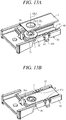
FIG. 13A is a diagram for explaining a jig preparation step in a cutting blade replacement method according to an embodiment of the present invention; -
FIG. 13B is a diagram for explaining the jig preparation step followingFIG. 13A ; -
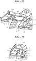
FIG. 14A a diagram for explaining a jig attachment step in the cutting blade replacement method according to the embodiment of the present invention; -
FIG. 14B is a diagram for explaining the jig attachment step followingFIG. 14A ; -
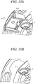
FIG. 15A is a diagram for explaining a bolt fastening step and a jig removal step in the cutting blade replacement method according to the embodiment of the present invention; and -
FIG. 15B is a diagram showing a state after the jig removal step in the cutting blade replacement method according to the embodiment of the present invention. - Hereinafter, an embodiment of the present invention is explained with reference to
FIGs. 1 to 15B . Although a cutting blade replacement jig according to an embodiment to the present invention can be used to replace cutting blades of various types of utility units, the following explanation is focused particularly on an example of use for replacing (exchanging) a cutting blade of a lawn mower. - The structure of the lawn mower will be explained first. The lawn mower related to this embodiment of the present invention is configured as a mobile lawn mower that performs lawn mowing work while navigating autonomously.
FIG. 1 is a side view showing schematically a configuration of alawn mower 100 on which the cutting blade replacement jig according to the embodiment of the present invention is utilized, andFIG. 2 is a perspective view of thelawn mower 100 seen obliquely from below. - As shown in
FIGs. 1 and 2 , thelawn mower 100 is equipped with abody 101 having a chassis and a frame, along with left and rightfront wheels 102 and left and rightrear wheels 103 that support thebody 101 above a ground surface GR so as to be capable of moving. An ECU 104, awork unit 105, awork actuator 106 for driving the work unit,movement actuators 107 for driving the rear wheels, acharging unit 108, and abattery 109 are installed in an interior space of thelawn mower 100 enclosed by the chassis and frame. TheECU 104 is configured so as to include an arithmetic processing unit having, inter alia, a CPU, ROM, RAM and other peripheral circuits. Thework actuator 106 andmovement actuators 107 are constituted as electric motors, for example. - Output shafts of the
movement actuators 107 are connected to rotating shafts of the left and rightrear wheels 103, respectively, so that themovement actuators 107 independently drive (rotate) the left and rightrear wheels 103. By establishing a difference between the rotating speeds of the left and rightrear wheels 103, thelawn mower 100 can be turned to an arbitrary direction. - The
charging unit 108 is connected by wires toterminals 110 provided at the front end of the frame and is also connected by wires to thebattery 109. Thebattery 109 is charged by connecting theterminals 110 through contacts to a charging station 200 (seeFIG. 3 ). Thebattery 109 is connected through wires to thework actuator 106 and themovement actuators 107, and theactuators battery 109. Twomagnetic sensors 111 are installed laterally spaced apart on the front end of thelawn mower 100. Themagnetic sensors 111 output signals indicating magnetic field magnitude (magnetic field strength). - Although not illustrated in the drawing, the
lawn mower 100 is further equipped with, inter alia, a Yaw sensor, a G sensor, a direction sensor, a contact sensor, wheel speed sensors, and a voltage sensor. The Yaw sensor outputs a signal indicating angular velocity (yaw rate) occurring around a height direction (z-axis) of thelawn mower 100. The G sensor outputs a signal indicating acceleration acting on thelawn mower 100 in the directions of three orthogonal axes (x-axis, y-axis, and z-axis). The direction sensor (geomagnetic field sensor) outputs a signal related to terrestrial magnetism. The contact sensor outputs an ON signal when the lawn mower 100 approaches or makes contact with an obstacle or the like. The wheel speed sensors output signals indicating the wheel speeds of the left and rightrear wheels 103. The voltage sensor outputs a signal indicating residual voltage of thebattery 109. - The
lawn mower 100 configured as set out above performs a lawn mowing work while autonomously navigating within a predefined working area.FIG. 3 is a plan view showing an example of a working area AR. The working area AR is delineated by aboundary wire 201 laid beforehand (e.g., buried a predetermined depth under the ground surface GR) in a garden (yard), for example, and theboundary wire 201 defines a movement range of thelawn mower 100. A magnetic field is generated in the working area AR by passing electric current through theboundary wire 201. Magnetic field strength in the working area AR is detected by a pair of left and rightmagnetic sensors 111. - Magnetic field strength varies with distance from the
boundary wire 201. TheECU 104 uses signals from themagnetic sensors 111 to determine whether thelawn mower 100 arrived at theboundary wire 201. When arrival at theboundary wire 201 is determined, control signals are output to the movement actuators 107 to turn thelawn mower 100 toward the inside of the working area AR as indicated by an arrow inFIG. 3 . In this manner, theECU 104 outputs control signals to the movement actuators 107 in accordance with signals from themagnetic sensors 111, whereby thelawn mower 100 navigates autonomously inside the working area AR. At this time, theECU 104 also outputs a control signal to thework actuator 106 in order to perform a lawn mowing work inside the working area AR. - The charging
station 200 for charging thebattery 109 is installed above theboundary wire 201. When the voltage sensor detects that voltage of thebattery 109 is too low during work, theECU 104 outputs control signals to the movement actuators 107 so as to return thelawn mower 100 to the chargingstation 200, along theboundary wire 201, for example, and then charge thebattery 109. When charging of thebattery 109 is finished, theECU 104 outputs control signals to the movement actuators 107 so as to separate thelawn mower 100 from the chargingstation 200 and thereafter drives thework actuator 106 to resume work. TheECU 104 also returns thelawn mower 100 to the chargingstation 200 upon work completion and keeps it standing by at the chargingstation 200 until the next work is started. - A detailed explanation of the structure of the
work unit 105 follows.FIG. 4 is enlarged view of a main part ofFIG. 2 . As shown inFIG. 4 , thework unit 105 has a substantiallycircular disk 1 rotatable around a vertical axis CL1 and a plurality (three in the drawing) of blades for mowing lawn (cutting blades) 2 attached to the peripheral edge of thedisk 1. Theblades 2 are fastened to the peripheral edge of thedisk 1 bybolts 6 andnuts 7 so as to be replaceable (seeFIG. 8 ). -
FIG. 5 is a cross-sectional view taken along line V-V ofFIG. 4 , andFIG. 6 is a perspective view of thedisk 1. InFIG. 5 , the up-down direction of thelawn mower 100 in the working is indicated by an arrow. As shown inFIGs. 5 and6 , thedisk 1 has atop surface 10a located above and abottom surface 10b located below in the gravity direction when thelawn mower 100 is working, and a through-hole 1a opens at a center region of thedisk 1. One end of a rotating shaft 3 extending along the axis CL1 is inserted into the through-hole 1a, and thedisk 1 is secured on the rotating shaft 3 by screwing anut 4 onto the one end of the rotating shaft 3. The rotating shaft 3 is connected to the work actuator 106 (FIG. 1 ) at another end and rotates thedisk 1 around the axis CL1 integrally with theblades 2 when driven by thework actuator 106. - A substantially ring-shaped
flange 11 is formed to project upward from around the whole periphery of thedisk 1.Arcuate cutouts 10 are formed radially inward of theflange 11 at three locations equally spaced in the circumferential direction. Radially inward of thecutouts 10, slopedportions 12 sloping away from the flange 11 (downward) are formed from predeterminedradial locations 1b to the radially outward cutouts 10. Outerperipheral surfaces 12a of the slopedportions 12 are formed in arcuate shape centered on the axis CL1 (FIG. 5 ). -
FIG. 7 is a plan view of asingle blade 2. As shown inFIG. 7 , theblade 2 has the overall shape of a substantially rectangular flat plate formed withblade edges 2a on opposite longitudinal side faces. A round through-hole 2b for attaching theblade 2 is formed near one end of the blade. -
FIG. 8 is an enlarged view of a main part ofFIG. 5 , andFIG. 9 is an exploded perspective view thereof. As seen inFIG. 8 and 9 , a through-hole 13 is formed in each slopedportion 12 ofdisk 1. The through-hole 13 hascircular hole portion 13a centered on an axis (center line) CL2 and a pair ofnotches 13b of predetermined width extending in radially opposite directions from the axis CL2 at the center (in circumferential direction around the axis CL1). Diameter of the through-hole 2b of theblade 2 is larger than diameter of thehole portion 13a. A threadedportion 61 of thebolt 6 is inserted into thehole portion 13a. - The threaded
portion 61 passes through the through-hole 2b of theblade 2 placed on thetop surface 10a of the slopedportion 12 of thedisk 1 and screw-engages thenut 7. Thebolt 6 is a hexagon socket head bolt, whosehead 62 is provided with ahexagonal socket 63 for inserting a tool. One surface of the head 62 (surface on opposite side from flange surface abutting the disk 1) is formed to slant at an angle toward the flange surface along its radial outer side. This minimizes projection of thehead 62 of thebolt 6 and smoothens the surface of thehead 62. - The
nut 7 has ahead 71, a substantiallycircular flange 72 provided on the bottom of thehead 71, and acylindrical portion 73 projecting downward from a bottom surface of theflange 72. Twoprojections 75 corresponding to thenotches 13b of the through-hole 13 of thedisk 1 protrude from anend surface 74 of thecylindrical portion 73. In a fastened state of thebolt 6 and thenut 7, thecylindrical portion 73 passes through the through-hole 2b of theblade 2 and itsend surface 74 abuts thetop surface 10a of the slopedportion 12 of thedisk 1, so that the slopedportion 12 is clamped between thebolt 6 and thenut 7. At this time, theprojections 75 of thenut 7 fit into thenotches 13b, thereby restricting the position of thenut 7 with respect to thedisk 1 and preventing rotation of thenut 7. - The
blade 2 is situated between theflange 72 of thenut 7 and the slopedportion 12 of thedisk 1. Diameter of the through-hole 2b of theblade 2 is larger than diameter of thecylindrical portion 73 and thickness of theblade 2 is thinner than length of thecylindrical portion 73. Therefore, theblade 2 can rotate aroundcylindrical portion 73 centered on the axis CL2 when thebolt 6 andnut 7 are fastened. - All of the three
blades 2 are attached to thedisk 1 by thebolts 6 and thenuts 7 in this manner. In the present embodiment, the cutting blade replacement jig described in the following makes attachment and detachment of theblades 2 simple, so that the work of replacing (exchanging) theblades 2 can be carried out with ease. -
FIG. 10 is a perspective view of a cuttingblade replacement jig 20 according to an embodiment of the present invention seen obliquely from above, andFIG. 11 is a perspective view seen obliquely from below.FIG. 11 additionally shows thehead 71 of anut 7. For convenience of description in the following, configurations of thejig 20 are explained assuming the front-rear (longitudinal), left-right (lateral) and up-down (vertical) directions of thejig 20 to be as defined in the drawings. Thejig 20 is made of resin material (e.g., polypropylene) and, with the exclusion its front end, has a symmetrical shape throughout in the left-right direction. - As shown in
FIGs. 10 and11 , thejig 20 has anoperating section 20A, and aretaining section 20B projecting forward from theoperating section 20A. Theoperating section 20A has a substantially rectangularflat plate 21 extending in the longitudinal and lateral directions, a pair oflateral side plates flat plate 21 on opposite lateral edges of theflat plate 21, and afront plate 24 erected orthogonal to theflat plate 21 and theside plates flat plate 21 and the front end of theside plates projection 25 is provided to protrude forward of thefront plate 24 from the top of each of theside plates -
FIG. 12A is a plan view of thejig 20, andFIG. 12B is a cross-sectional view of thejig 20 cut along line B-B ofFIG. 12A . As shown inFIG. 12A and 12B , afront surface 24a of thefront plate 24 is arcuately shaped to have approximately the same curvature as the outerperipheral surfaces 12a of the slopedportions 12 of the disk 1 (FIG. 6 ). A front end of theflat plate 21 is formed at a central region in the lateral direction with an angularU-shaped notch 21a that passes completely through theflat plate 21 vertically. - The
front plate 24 is formed at a central region in the lateral direction with an orthogonally erectedstopper 26 facing thenotch 21a.Notches 24b are formed to a predetermined depth from an upper end surface of thefront plate 24 on opposite lateral sides of thestopper 26, and thestopper 26 is supported on thefront plate 24 at its bottom end to be swingable forward and rearward around the bottom end as a pivot. As shown inFIG. 12B , thestopper 26 projects above thefront plate 24 to where its upper end surface is level with upper end surfaces of theside plates projection 26a protrudes forward from a front surface of thestopper 26. - As shown in
FIGs. 10 and11 , the retainingsection 20B has a pair oflateral side walls front surface 24a of thefront plate 24 and abottom wall 29 interconnecting bottoms of theside walls nut holder 30 for holding anut 7 is provided between thefront surface 24a of thefront plate 24 and arear end surface 29a of thebottom wall 29. Thenut holder 30 has a pair of left andright bases 31 projecting from thefront surface 24a of thefront plate 24 forward along inner side surfaces of rear ends of theside walls right pawls 32 projecting forward from forward ends of thebases 31 apart from and parallel to theside walls pawls 32 can expand and contract laterally. - The left and
right pawls 32 face each other separated by a predetermined distance (length) L1 (FIG. 10 ) and each has aninner side surface 32a extending in the longitudinal direction. As seen inFIG. 12A , ends 31a of thebases 31 on the side of theinner side surfaces 32a are arcuately formed along an imaginary circle C1 centered on a point P a predetermined distance forward from theprojection 26a of thestopper 26. Forward ends of thepawls 32 are provided withprojections 32b that protrude laterally inward. Theprojections 32b are formed to have smoothly rounded protruding surfaces, and their rear end surfaces lie on the imaginary circle C1. A vertical axis (center line) CL3 that passes through the point P is shown inFIG. 12B . - As shown in
FIG. 11 , thehead 71 of thenut 7 has acylindrical portion 71a of approximately the same diameter as the imaginary circle C1 (FIG. 12A ), and acutaway portion 71c with a pair ofparallel side surfaces 71b formed by cutting away parts of the circumference of thecylindrical portion 71a. Distance (length) L2 between the side surfaces 71b is roughly equal to distance L1 (FIG. 10 ) of theinner side surface 32a of thepawls 32. Therefore, thehead 71 of thenut 7 can be fitted between thepawls 32 along theends 31a of thebases 31, the inner side surfaces 32a of thepawls 32, and rear end surfaces of theprojections 32b (seeFIG. 12A ). - As shown in
FIG. 12A , top surfaces of thebases 31 andpawls 32 are formed from their forward ends throughout along thepawls 32 withrecesses 33 within an imaginary circle C2 centered on the point P. Diameter of the imaginary circle C2 is approximately equal to diameter of theflange 72 of thenut 7, and theflange 72 fits into therecesses 33 and is placed on the top surfaces of therecesses 33. Depth of therecesses 33 is approximately equal to thickness of theflange 72, and theflange 72 can fit in therecesses 33 at an even level with the top surfaces of thebases 31. - As shown in
FIG. 10 , agroove 34 of predetermined depth is formed in the top surface of thebottom wall 29 from itsfront end surface 29b up to itsrear end surface 29a, and guides 35 are formed on opposite lateral sides of thegroove 34. Length of thegroove 34 in the lateral direction is longer than length L2 of thehead 71 of the nut 7 (FIG. 11 ) and depth of thegroove 34 is deeper than height of thehead 71 of thenut 7. Top surfaces of theguides 35 are located substantially on the same plane as the top surfaces of therecesses 33. As a result, theflange 72 can slide along theguides 35, so that thenut 7 can be moved forward from thegroove 34 without interference between thehead 71 of thenut 7 and thebottom wall 29. - A
blade holder 40 for holding an associated one of theblades 2 is provided on thelateral side walls blade holder 40 hassteps 41 provided on lateral inner faces of theside walls blade 2, and two lateral engagingpawls 42 provided on top surfaces of thesteps 41 for engaging theblade 2. Theblade holder 40 also includes thestopper 26 for restricting position of theblade 2 in the longitudinal direction. Length from the left end surface of thestep 41 on theside wall 27 side to the right end surface of thestep 41 on theside wall 28 side is about equal to width of theblade 2. The top surface of thesteps 41 are located substantially on the same plane as the top surfaces of the bases 31 (excluding the recesses 33), and theblade 2 can be set in place across the top surfaces of thebases 31 and the top surfaces of thesteps 41. - The engaging
pawls 42 are provided at intermediate locations of theside walls FIGs. 10 and11 , theside walls nut holder 30 with forward and rearwardthin portions 43 of thin vertical thickness and the engagingpawls 42 are supported on theside walls thin portions 43. The engagingpawls 42 extend vertically and are formed on their laterally inward sides with vertical through-holes 44 that divide thesteps 41 about midway.Protrusions 42a are provided to project laterally inward at top ends of the engaging pawls 42 and grips 42b are provided to project laterally outward at bottom ends thereof. Theprotrusions 42a can be swung laterally by a gripping force applied to and removed from thegrips 42b, whereby distance between the opposingprotrusions 42a can be expanded and contracted. - As seen in
FIG. 12B , bottom surfaces of theprotrusions 42a are arranged a predetermined distance (length) L3 above the top surfaces of thesteps 41 and at same height as a bottom surface of theprojection 26a of thestopper 26. The predetermined length L3 corresponds to thickness of theblade 2. Theblade 2 is set in place on the top surfaces of thesteps 41 by applying the gripping force to thegrips 42b in order to expand width betweenprotrusions 42a of thelateral engaging pawls 42 and then sliding the rear edge of theblade 2 underneath theprojection 26a of thestopper 26. When the gripping force is thereafter removed, the distance between theprotrusions 42a contracts, so that opposite lateral edges of theblade 2 are engaged by theprotrusions 42a, whereby the rear edge of theblade 2 is engaged by theprojection 26a of thestopper 26. In this condition, theblade 2 can be slid forward along the top surface of thesteps 41. - As shown in
FIGs. 10 and11 , a generallyconical protuberance 50 is provided on a front end surface of the oneside wall 27. Theprotuberance 50 can be used to remove dirt stuck in thesocket 63 of thebolt 6, thereby facilitating removal and attachment of thebolt 6 for blade replacement after the lawn mowing work. Although not illustrated, thejig 20 can be placed inside the charging station 200 (FIG. 3 ) for storage through an openable cover provided on the chargingstation 200. - Now follows an explanation of a cutting blade replacement method according to an embodiment of the present invention. The case of attaching a
new blade 2 to thedisk 1 is explained in the following. - First, a
jig 20 pre-loaded with anut 7 and ablade 2 is prepared (jig preparation step). In this case, as shown inFIG. 13A , thenut 7 is fitted between the twopawls 32 of the nut holder 30 (FIG. 10 ), and theflange 72 of thenut 7 is placed on the top surface of the circular recesses 33 (FIG. 10 ). In this condition, the center line CL3 of thenut holder 30 and a center line CL4 of thenut 7 substantially coincide, and thenut 7 is positioned with its side surfaces 71b opposite the inner side surfaces 32a of thepawls 32. The twoprojections 75 at the end of thecylindrical portion 73 of thenut 7 are therefore positioned in the lateral direction of thejig 20. - Following this, the
grips 42b of the engagingpawls 42 are gripped to expand thelateral protrusions 42a laterally, and theblade 2 is set in place on thesteps 41 of theblade holder 40 while sliding the rear edge part of theblade 2 underneath theprojection 26a of thestopper 26. In this condition, the center line CL3 of thenut holder 30, the center line CL4 of thenut 7, and a center line CL5 passing through the through-hole 2b of theblade 2 coincide. - Therefore, as shown in
FIG. 13B , theflange 72 of thenut 7 is covered by the surface of theblade 2 surrounding the through-hole 2b, and the top surface of theblade 2 is locked by theprotrusions 42a of the engaging pawls 42 and theprojection 26a of thestopper 26. As a result, thenut 7 andblade 2 are integrally fastened together with thejig 20, and the blade edges 2a of theblade 2 are covered by theside walls nut 7 andblade 2 fixed to thejig 20, the center line CL5 passing through the through-hole 2b of theblade 2 and the center line CL4 of thenut 7 substantially coincide with the center line CL3 of thenut holder 30 of the jig (FIG. 12B ). - Next, the
jig 20 is attached to the peripheral edge of the disk 1 (jig attachment step). In this case, thelawn mower 100 is turned upside down or elevated, and theretaining section 20B is inserted into the associated one of thecutouts 10 of thedisk 1 from radially outside in the direction of arrow A (radially inward direction), as shownFIG. 14A . More specifically, the retainingsection 20B is inserted facing thetop surface 10a of thedisk 1 until thestopper 26 abuts the outerperipheral surface 12a of the slopedportion 12 so that the slopedportion 12 of thedisk 1 is located in a gap between the pair of left andright projections 25 and theside walls jig 20 is disposed in the peripheral edge region of thedisk 1 so that the center line CL2 of the through-hole 13 of the slopedportion 12 of the disk 1 (FIG. 8 ) and the center line CL5 of the through-hole 2b of theblade 2 coincide. - Therefore, as shown in
FIG. 14B , theprojections 75 of the nut held in thejig 20 fit in thenotches 13b of the through-hole 13 of thedisk 1. As a result, thejig 20 can be attached to thedisk 1 with thedisk 1 vertically clamped between the left andright projections 25 and theprojections 75 of thenut 7. Therefore, thejig 20 no longer needs to be held by hand once theprojections 75 fit in thenotches 13b. Whether theprojections 75 are fitted in thenotches 13b can be checked visually. Whether theprojections 75 are fitted can also be ascertained from a metallic sound occurring when theprojections 75 fit into thenotches 13b. - Next, the threaded
portion 61 of abolt 6 is inserted into the through-hole 13 from thebottom surface 10b side of thedisk 1 and screwed into the nut 7 (bolt fastening step). As shown inFIG. 15A , this fastens thebolt 6 to thenut 7 and fixes theblade 2 to thedisk 1. In the condition with thejig 20 attached to thedisk 1, fastening of thebolt 6 is easy because thenut 7 is prevented from rotating owing to theprojections 75 of thenut 7 being fitted into the through-hole 13 of thedisk 1. Since thebottom surface 10b side of thedisk 1 is openly exposed, a tool used to fasten the bolt is easy to maneuver. - Next, the
operating section 20A of thejig 20 is grasped and thejig 20 is pulled toward the radially outward side of thedisk 1, i.e., in the direction of arrow B inFIG. 15A (jig removal step). Theguides 35 of the jig 20 (FIG. 12A ) therefore move (slide) along theflange 72 of thenut 7 as thesteps 41 of the jig 20 (FIG. 12A ) move (slide) along theblade 2. As a result, as shown inFIG. 15B , thejig 20 can be removed from thedisk 1 while leaving theblade 2 attached to thedisk 1. The foregoing steps complete the work of replacing (attaching) theblade 2. When theblade 2 is to be removed from thedisk 1, thebolt 6 needs to be loosened. In this case, the work of loosening thebolt 6 and removing theblade 2 can be performed without using thejig 20 because theprojections 75 engage thenotches 13b and restrict the position of thenut 7 with respect to thedisk 1. - As shown in
FIG. 15B , when thejig 20 has been removed, the end of theblade 2 faces radially inward of thedisk 1. When thedisk 1 is rotated in this condition, theblade 2 rotates around the center line CL5 owing to centrifugal force to face radially outward, as shown inFIG. 4 . As a result, theblade 2 projects radially outward from thedisk 1, making lawn mowing work possible. In the present embodiment, theblades 2 are attached to thedisk 1 through thecutouts 10 and the outer periphery of thedisk 1 is located above theblades 2. Therefore, since theblades 2 are not fully exposed during lawn mowing work, i.e., the upside of theblades 2 are guarded by thedisk 1, work safety can be considerably enhanced. - The present embodiments can achieve advantages and effects such as the following:
- (1) The cutting
blade replacement jig 20 of the utility unit according to the embodiment of the present invention is used to individually replace theblades 2 which are formed with the through-hole 2b for passing thebolt 6 and are attached to the peripheral edge of thedisk 1 by thebolts 6 passed through the through-holes 13 formed in the peripheral edge of thedisk 1 and thenuts 7 fastened to the bolt 6 (FIG. 8 ). This cuttingblade replacement jig 20 includes thenut holder 30 that holds thenut 7 and theblade holder 40 that holds theblade 2 on the nut 7 (flange 72) held in thenut holder 30 in a state with the center line CL5 of the through-hole 2b and the center line CL4 of thenut 7 substantially aligned (FIGs. 10 and11 ). The holding of thenut 7 and theblade 2 in thenut holder 30 and theblade holder 40, respectively, in this manner makes it possible to fasten thebolt 6 in thenut 7 via the through-hole 2b of theblade 2 while simultaneously restraining thenut 7 and theblade 2, whereby the work of replacing theblade 2 can be easily and efficiently performed. - (2) The
nut holder 30 includes therecess 33 on which thenut 7 is mounted. Theblade holder 40 includes the stopper 26 (projection 26a) and engaging pawls 42 (protrusions 42a) that engage with theblade 2 disposed on thenut 7 mounted in therecess 33 and that integrally hold thenut 7 and the blade 2 (FIGs. 10 and11 ). Since the holding of thenut 7 and theblade 2 integrally in thejig 20 in this manner prevents detachment of thenut 7 andblade 2 from thejig 20, thejig 20 is easy to handle and the work of replacing theblade 2 is facilitated. - (3) The
jig 20 includes theguides 35 andsteps 41 that slidably support thenut 7 and theblade 2 so that thenut 7 and theblade 2 are integrally detached from the jig 20 (FIGs. 10 and12A ). Therefore, after thebolt 6 is fastened in thenut 7 integrally retained in thejig 20, thejig 20 can be easily removed. - (4) The
jig 20 is equipped with theprojections 25 capable of attaching theblade 2 to the peripheral edge of thedisk 1, with thenut 7 andblade 7 still integrally held, so that the center line CL5 of the through-hole 2b of theblade 2 substantially coincides with the axis CL2 of the through-hole 13 of the disk (FIG. 14B ). As a result, thejig 20 can be kept attached to thedisk 1 without using the hands, so that the work of fastening thebolt 6 can be easily performed. - (5) The end of the nut 7 (projections 75) is fitted in the
notches 13b of thedisk 1, so that thenut 7 is mounted to be non-rotatable with respect to thedisk 1, and thenut holder 30 includes thepawls 32 that restrict the position of thenut 7 in the circumferential direction (FIG. 10 ). Therefore, since thejig 20 can prevent rotation of thenut 7, thebolt 6 can be easily fastened. - (6) The cutting blade replacement method of the utility unit according to the embodiment of the present invention is a method for replacing the
blade 2, formed with the through-hole 2b through which thebolt 6 passes and attached to the peripheral edge of thedisk 1, using thebolt 6 passed through the through-hole 13 formed in the peripheral edge of thedisk 1 and thenut 7 fastened to thebolt 6. In this method, thenut 7 and theblade 2 are in advance held in thejig 20 in a state with the center line CL3 of thenut 7 and the center line CL5 of the through-hole 2b of theblade 2 substantially aligned (FIGs. 13A and 13b ), thejig 20 is disposed on the peripheral edge of thedisk 1 with the center line CL5 of the through-hole 2b of theblade 2 and the axis CL2 of the through-hole 13 of thedisk 1 substantially aligned (FIGs. 14A and 14B ), and thebolt 6 is passed through the through-hole 13 formed at the peripheral edge of thedisk 1 and the through-hole 2b of theblade 2, and is screwed into thenut 7 to fasten theblade 2 to the disk 1 (FIGs. 15A and 15B ). According to this cutting blade replacement method, thejig 20 can be used to simultaneously arrange thenut 7 and theblade 2 at desired positions relative to the through-hole 13 of thedisk 1. Theblade 2 can therefore be efficiently attached to thedisk 1 and the work of replacing theblade 2 is easy. - In the above embodiment, the function of a fastening member holder is configured so that the
nut holder 30 for holding thenut 7 are provided in thejig 20. In other words, thebolt 6 that passes through the disk through-hole 13 and thenut 7 fastened to thebolt 6 are configured as a first fastening member and a second fastening member, respectively. Alternatively, the bolt can be held by a jig. In other words, the nut can be configured as the first fastening member and the bolt can be configured as the second fastening member, and the configuration of the fastening member holder is not limited to the above configuration. - In the above embodiment, the
blade 2 is held on theflange 72 of thenut 7 by theblade holder 40 in a state with the center line CL5 of the through-hole 2b of the blade 2 (cutting blade through hole) substantially aligned with the center line CL4 of thenut 7, but the configuration of the cutting blade holder is not limited to this. Although in the above embodiment, theflange 72 of thenut 7 is mounted on the top surface of therecess 33 of thejig 20, the configuration of a mounted portion is not limited to this. In the above embodiment, thenut 7 and theblade 2 are held integrally in thejig 20 by thestopper 26 and two engagingpawls 42 of thejig 20, more exactly by theprojection 26a of the stopper 26 (first cutting blade engaging portion) that restricts longitudinal direction (front-rear direction) movement of theblade 2 and theprotrusions 42a of the engaging pawls 42 (second cutting blade engaging portion) that restrict lateral direction (left-right direction) position of theblade 2, However, the configuration of a cutting blade engaging portions is not limited to this. Although in the above embodiment, theblade 2 is formed in a substantially rectangular flat plate-like shape and opposite sides of theblade 2 are provided withblade edges 2a, the configuration of a cutting blade is not limited to this. - Although in the above embodiment, the
nut 7 and theblade 2 are configured to detach integrally from thejig 20 utilizing theguides 35 andsteps 41 that slidably support thenut 7 and theblade 2, the configuration of the sliding support is not limited to this. In the above embodiment, thejig 20 is attached to the peripheral edge part of thedisk 1 via theprojections 25 so the center line CL5 of the through-hole 2b of theblade 2 substantially aligns with the center line CL3 of the disk through-hole 13, the configuration of a jig attachment portion is not limited to this. In the above embodiment, the position of thenut 7 in the circumferential direction is restricted by means of theprojections 75 at the end of thenut 7 fitted in thenotches 13b of the through-hole 13 of thedisk 1, but the configuration of a position restricting portion is not limited to this. - In the above, the cutting
blade replacement jig 20 is used when replacing ablade 2 of thelawn mower 100 capable of autonomous navigation. However, a cutting blade replacement jig of the present invention can be similarly used in the case of replacing a cutting blade of some other kind of utility unit. For example, the jig of the present invention can be similarly used in the case of changing a cutting blade attached to a hand-pushed lawn mower, a hand-held lawn mower, or other type of lawn mower, or a utility unit other than a lawn mower (e.g., a brush cutter or the like). - The above embodiment can be combined as desired with one or more of the aforesaid modifications. The modifications can also be combined with one another.
- According to the present invention, a second fastening member is fastened to a first fastening member, while the second fastening member and a cutting blade are integrally held. Therefore, a work of replacing the cutting blade can be easily and efficiently performed.
- Above, while the present invention has been described with reference to the preferred embodiments thereof, it will be understood, by those skilled in the art, that various changes and modifications may be made thereto without departing from the scope of the appended claims.
- A cutting blade replacement jig (20) for replacing a cutting blade (2) of a utility unit, the cutting blade (2) being attached to a peripheral edge part of a disk (1) by a first fastening member (6) and a second fastening member (7) fastened to the first fastening member (6), the first fastening member (6) passing through a disk through hole (13) formed in the peripheral edge part of the disk (1) and a cutting blade through hole (2b) formed in the cutting blade (2). The cutting blade replacement jig (20) includes a fastening member holder (30) holding the second fastening member (7), and a cutting blade holder (40) holding the cutting blade (2) on the second fasting member (7) held in the fastening member holder (30).
Claims (12)
- A cutting blade replacement jig (20) for replacing a cutting blade (2) of a utility unit, the cutting blade (2) being attached to a peripheral edge part of a disk (1) by a first fastening member (6) and a second fastening member (7) fastened to the first fastening member (6), the first fastening member (6) passing through a disk through hole (13) formed in the peripheral edge part of the disk (1) and a cutting blade through hole (2b) formed in the cutting blade (2),
the cutting blade replacement jig comprising:a fastening member holder (30) configured to hold the second fastening member (7); anda cutting blade holder configured to hold the cutting blade (2) on the second fasting member (7) held in the fastening member holder (30) in a state where a center line (CL5) of the cutting blade through hole (2b) and a center line (CL4) of the second fasting member (7) are aligned. - The cutting blade replacement jig according to claim 1, wherein the fastening member holder (30) includes a mounted portion (33) on which the second fastening member (7) is mounted, and
the cutting blade holder (40) includes a cutting blade engaging portion (26, 42) configured to engage with the cutting blade (2) disposed on the second fastening member (7) mounted on the mounted portion (33) to integrally hold the second fastening member (7) and the cutting blade (2). - The cutting blade replacement jig according to claim 2, further comprising a sliding support (35, 41) configured to slidably support the second fastening member (7) and the cutting blade (2) so that the second fastening member (7) and the cutting blade (2) are integrally detached from the cutting blade replacement jig (20).
- The cutting blade replacement jig according to claim 3, wherein the cutting blade (2) is formed in a rectangular flat plate shape, and
the cutting blade engaging portion includes a first cutting blade engaging portion (26) engaging with an end of the cutting blade (2) in a longitudinal direction to restrict a movement of the cutting blade (2) in the longitudinal direction and a second cutting blade engaging portion (42) engaging with both ends of the cutting blade (2) in a lateral direction to restrict a movement of the cutting blade (2) in the lateral direction. - The cutting blade replacement jig according to claim 4, wherein the second cutting blade engaging portion (42) is configured to be swingable in the lateral direction of the cutting blade (2).
- The cutting blade replacement jig according to any one of claims 2 to 5, further comprising a side wall (27, 28) covering a blade edge (2a) of the cutting blade (2) held by the cutting blade engaging portion (26, 42).
- The cutting blade replacement jig according to any one of claims 2 to 6, further comprising a jig attaching portion (25) attachable the cutting blade replacement jig (20) to the peripheral edge part of the disk (1) in a state where the second fastening member (7) and the cutting blade (2) are integrally held, so that the center line (CL5) of the cutting blade through hole (13) and a center line (CL2) of the disk through hole (13) align.
- The cutting blade replacement jig according to any one of claims 1 to 7, wherein the second fastening member (7) is non-rotatably engaged with the disk through hole (13), and
the fastening member holder (30) includes a position restricting portion (32) restricting a position of the second fastening member (7) in a circumferential direction. - The cutting blade replacement jig according to claim 8, wherein an end portion of the second fastening member (7) includes a projection (75) fitting non-rotatably into a notch (13b) formed in the disk (1).
- A cutting blade replacement method for replacing a cutting blade (2) of a utility unit, the cutting blade (2) being attached to a peripheral edge part of a disk (1) by a first fastening member (6) and a second fastening member (7) fastened to the first fastening member (6), the first fastening member (6) passing through a disk through hole (13) formed in the peripheral edge part of the disk (1) and a cutting blade through hole (2b) formed in the cutting blade (2),
the cutting blade replacement method comprising:holding the second fastening member (7) and the cutting blade (2) in a cutting blade replacement jig (20), in a state of aligning a center line (CL4) of the second fasting member (7) and a center line (CL5) of the cutting blade through hole (2b) in advance;placing the cutting blade replacement jig (20) at the peripheral edge part of the disk (1) so that the center line (CL5) of the cutting blade through hole (2b) aligns with a center line (CL2) of the disk through hole (13); andattaching the cutting blade (2) to the disk (1) by making the first fastening member (6) pass through the cutting blade through hole (2b) of the cutting blade (2) held in the cutting blade replacement jig (20) placed at peripheral edge part of the disk (1) and the disk through hole (13) and by screwing the first fastening member (6) to the second fastening member (7). - The cutting blade replacement method according to claim 10, further comprising after attaching the cutting blade (2) to the disk (1), pulling out the cutting blade replacement jig (20) from the disk (1) by sliding the cutting blade replacement jig (20) relative to the second fastening member (7) and the cutting blade (2).
- The cutting blade replacement method according to claim 10 or 11, the placing includes non-rotatably fitting the second fastening member (7) into a notch (13b) formed in the disk (1).
Applications Claiming Priority (1)
| Application Number | Priority Date | Filing Date | Title |
|---|---|---|---|
| JP2016124640A JP6636399B2 (en) | 2016-06-23 | 2016-06-23 | Cutting blade replacement jig of working machine and cutting blade replacement method |
Publications (2)
| Publication Number | Publication Date |
|---|---|
| EP3262915A1 true EP3262915A1 (en) | 2018-01-03 |
| EP3262915B1 EP3262915B1 (en) | 2019-11-13 |
Family
ID=59034482
Family Applications (1)
| Application Number | Title | Priority Date | Filing Date |
|---|---|---|---|
| EP17174659.7A Active EP3262915B1 (en) | 2016-06-23 | 2017-06-07 | Cutting blade replacement jig and method |
Country Status (4)
| Country | Link |
|---|---|
| US (1) | US11051451B2 (en) |
| EP (1) | EP3262915B1 (en) |
| JP (1) | JP6636399B2 (en) |
| CN (1) | CN107535176B (en) |
Cited By (1)
| Publication number | Priority date | Publication date | Assignee | Title |
|---|---|---|---|---|
| WO2019226415A1 (en) * | 2018-05-25 | 2019-11-28 | The Toro Company | Systems and methods for operating a robotic machine in an autonomous mode and a manual mode |
Families Citing this family (5)
| Publication number | Priority date | Publication date | Assignee | Title |
|---|---|---|---|---|
| US10433480B2 (en) * | 2016-04-20 | 2019-10-08 | Mtd Products Inc | Low-energy blade system having a quick-attach mechanism |
| EP3474654B1 (en) | 2016-06-24 | 2020-06-24 | MTD products Inc | High-efficiency cutting system |
| EP3691438B1 (en) | 2017-10-06 | 2023-06-14 | MTD Products Inc | High-efficiency lawn maintenance tool and high-efficiency cutting blade |
| CN112616418B (en) * | 2020-12-25 | 2023-09-26 | 南京苏美达智能技术有限公司 | Blade replacing structure for mower |
| CA3223635A1 (en) * | 2021-06-22 | 2022-12-29 | Shouchuan FENG | Blade assembly, power head and lawn mower |
Citations (4)
| Publication number | Priority date | Publication date | Assignee | Title |
|---|---|---|---|---|
| EP1588599A1 (en) * | 2004-04-21 | 2005-10-26 | Lely Enterprises AG | A mowing device, a knife adapter for such a mowing device and a retainer for such a mowing device |
| JP2008054568A (en) | 2006-08-31 | 2008-03-13 | Atex Co Ltd | Implement for exchanging reaping blade of mower |
| EP2939517A1 (en) * | 2014-04-30 | 2015-11-04 | CNH Industrial Belgium nv | Mower conditioner knife removal tool with wear gauge |
| EP3075221A1 (en) * | 2015-03-27 | 2016-10-05 | Honda Motor Co., Ltd. | Lawn mower with blade disc |
Family Cites Families (4)
| Publication number | Priority date | Publication date | Assignee | Title |
|---|---|---|---|---|
| US6272724B1 (en) * | 2000-03-23 | 2001-08-14 | Kevin R. Sterling | Blade removing tool for rotary lawn mowers |
| US20010035080A1 (en) * | 2000-03-27 | 2001-11-01 | Adams Gary L. | Hand tool for holding a lawn mower blade |
| US20010035077A1 (en) * | 2000-03-28 | 2001-11-01 | Adams Gary L. | Hand tool for removing a lawn mower blade |
| US7490459B2 (en) * | 2003-03-12 | 2009-02-17 | Vermeer Manufacturing Company | Mowing device, a knife adapter for such a mowing device and a retainer for such a mowing device |
-
2016
- 2016-06-23 JP JP2016124640A patent/JP6636399B2/en not_active Expired - Fee Related
-
2017
- 2017-05-17 CN CN201710346440.6A patent/CN107535176B/en not_active Expired - Fee Related
- 2017-05-24 US US15/604,323 patent/US11051451B2/en active Active
- 2017-06-07 EP EP17174659.7A patent/EP3262915B1/en active Active
Patent Citations (4)
| Publication number | Priority date | Publication date | Assignee | Title |
|---|---|---|---|---|
| EP1588599A1 (en) * | 2004-04-21 | 2005-10-26 | Lely Enterprises AG | A mowing device, a knife adapter for such a mowing device and a retainer for such a mowing device |
| JP2008054568A (en) | 2006-08-31 | 2008-03-13 | Atex Co Ltd | Implement for exchanging reaping blade of mower |
| EP2939517A1 (en) * | 2014-04-30 | 2015-11-04 | CNH Industrial Belgium nv | Mower conditioner knife removal tool with wear gauge |
| EP3075221A1 (en) * | 2015-03-27 | 2016-10-05 | Honda Motor Co., Ltd. | Lawn mower with blade disc |
Cited By (1)
| Publication number | Priority date | Publication date | Assignee | Title |
|---|---|---|---|---|
| WO2019226415A1 (en) * | 2018-05-25 | 2019-11-28 | The Toro Company | Systems and methods for operating a robotic machine in an autonomous mode and a manual mode |
Also Published As
| Publication number | Publication date |
|---|---|
| CN107535176A (en) | 2018-01-05 |
| JP6636399B2 (en) | 2020-01-29 |
| JP2017225407A (en) | 2017-12-28 |
| EP3262915B1 (en) | 2019-11-13 |
| US11051451B2 (en) | 2021-07-06 |
| CN107535176B (en) | 2020-11-17 |
| US20170367260A1 (en) | 2017-12-28 |
Similar Documents
| Publication | Publication Date | Title |
|---|---|---|
| EP3262915B1 (en) | Cutting blade replacement jig and method | |
| US10858041B2 (en) | All wheel drive robotic vehicle with steering brake | |
| EP3136835B1 (en) | Improved robotic work tool | |
| JP7038536B2 (en) | Work vehicle | |
| EP2590879B1 (en) | Automated guided vehicle (agv) system | |
| US9248701B2 (en) | Vehicle wheel changing method | |
| KR20130092450A (en) | Lawn mower | |
| DE102018212412A1 (en) | Autonomous work tool | |
| JP7001551B2 (en) | Work vehicle | |
| EP3586591A1 (en) | Work vehicle | |
| DE112019007848T5 (en) | STATION AND POWER SUPPLY DEVICE OF AN AUTONOMOUSLY PROCEEDING WORK MACHINE | |
| US20230345870A1 (en) | Means for adjusting cutting height of a powered lawn mower | |
| EP4368007A1 (en) | Garden tool with toollessly interchangeable wheel | |
| US20250185536A1 (en) | A robotic lawn mower | |
| WO2023150032A1 (en) | Autonomous working vehicle system having base station with canopy | |
| JP2019216674A (en) | base station | |
| EP4662999A1 (en) | A robotic lawn mower with wheel brush device | |
| EP4487670A1 (en) | A robotic lawn mower with enhanced cutting properties | |
| CN223702462U (en) | Intelligent outdoor work vehicles | |
| CN223702463U (en) | Intelligent outdoor work vehicles with collision detection devices | |
| US20250204315A1 (en) | Robotic lawnmower with increased cutting properties | |
| JP7001552B2 (en) | Work vehicle | |
| JP7129696B2 (en) | Work machine charger | |
| JP7018831B2 (en) | Work vehicle |
Legal Events
| Date | Code | Title | Description |
|---|---|---|---|
| PUAI | Public reference made under article 153(3) epc to a published international application that has entered the european phase |
Free format text: ORIGINAL CODE: 0009012 |
|
| STAA | Information on the status of an ep patent application or granted ep patent |
Free format text: STATUS: REQUEST FOR EXAMINATION WAS MADE |
|
| 17P | Request for examination filed |
Effective date: 20170607 |
|
| AK | Designated contracting states |
Kind code of ref document: A1 Designated state(s): AL AT BE BG CH CY CZ DE DK EE ES FI FR GB GR HR HU IE IS IT LI LT LU LV MC MK MT NL NO PL PT RO RS SE SI SK SM TR |
|
| AX | Request for extension of the european patent |
Extension state: BA ME |
|
| RIC1 | Information provided on ipc code assigned before grant |
Ipc: A01D 34/73 20060101AFI20181207BHEP |
|
| GRAP | Despatch of communication of intention to grant a patent |
Free format text: ORIGINAL CODE: EPIDOSNIGR1 |
|
| STAA | Information on the status of an ep patent application or granted ep patent |
Free format text: STATUS: GRANT OF PATENT IS INTENDED |
|
| INTG | Intention to grant announced |
Effective date: 20190206 |
|
| GRAS | Grant fee paid |
Free format text: ORIGINAL CODE: EPIDOSNIGR3 |
|
| GRAA | (expected) grant |
Free format text: ORIGINAL CODE: 0009210 |
|
| STAA | Information on the status of an ep patent application or granted ep patent |
Free format text: STATUS: THE PATENT HAS BEEN GRANTED |
|
| AK | Designated contracting states |
Kind code of ref document: B1 Designated state(s): AL AT BE BG CH CY CZ DE DK EE ES FI FR GB GR HR HU IE IS IT LI LT LU LV MC MK MT NL NO PL PT RO RS SE SI SK SM TR |
|
| REG | Reference to a national code |
Ref country code: CH Ref legal event code: EP Ref country code: AT Ref legal event code: REF Ref document number: 1200703 Country of ref document: AT Kind code of ref document: T Effective date: 20191115 |
|
| REG | Reference to a national code |
Ref country code: IE Ref legal event code: FG4D |
|
| REG | Reference to a national code |
Ref country code: DE Ref legal event code: R096 Ref document number: 602017008598 Country of ref document: DE |
|
| REG | Reference to a national code |
Ref country code: NL Ref legal event code: MP Effective date: 20191113 |
|
| REG | Reference to a national code |
Ref country code: LT Ref legal event code: MG4D |
|
| PG25 | Lapsed in a contracting state [announced via postgrant information from national office to epo] |
Ref country code: LT Free format text: LAPSE BECAUSE OF FAILURE TO SUBMIT A TRANSLATION OF THE DESCRIPTION OR TO PAY THE FEE WITHIN THE PRESCRIBED TIME-LIMIT Effective date: 20191113 Ref country code: BG Free format text: LAPSE BECAUSE OF FAILURE TO SUBMIT A TRANSLATION OF THE DESCRIPTION OR TO PAY THE FEE WITHIN THE PRESCRIBED TIME-LIMIT Effective date: 20200213 Ref country code: FI Free format text: LAPSE BECAUSE OF FAILURE TO SUBMIT A TRANSLATION OF THE DESCRIPTION OR TO PAY THE FEE WITHIN THE PRESCRIBED TIME-LIMIT Effective date: 20191113 Ref country code: NL Free format text: LAPSE BECAUSE OF FAILURE TO SUBMIT A TRANSLATION OF THE DESCRIPTION OR TO PAY THE FEE WITHIN THE PRESCRIBED TIME-LIMIT Effective date: 20191113 Ref country code: LV Free format text: LAPSE BECAUSE OF FAILURE TO SUBMIT A TRANSLATION OF THE DESCRIPTION OR TO PAY THE FEE WITHIN THE PRESCRIBED TIME-LIMIT Effective date: 20191113 Ref country code: SE Free format text: LAPSE BECAUSE OF FAILURE TO SUBMIT A TRANSLATION OF THE DESCRIPTION OR TO PAY THE FEE WITHIN THE PRESCRIBED TIME-LIMIT Effective date: 20191113 Ref country code: NO Free format text: LAPSE BECAUSE OF FAILURE TO SUBMIT A TRANSLATION OF THE DESCRIPTION OR TO PAY THE FEE WITHIN THE PRESCRIBED TIME-LIMIT Effective date: 20200213 Ref country code: GR Free format text: LAPSE BECAUSE OF FAILURE TO SUBMIT A TRANSLATION OF THE DESCRIPTION OR TO PAY THE FEE WITHIN THE PRESCRIBED TIME-LIMIT Effective date: 20200214 Ref country code: PL Free format text: LAPSE BECAUSE OF FAILURE TO SUBMIT A TRANSLATION OF THE DESCRIPTION OR TO PAY THE FEE WITHIN THE PRESCRIBED TIME-LIMIT Effective date: 20191113 Ref country code: PT Free format text: LAPSE BECAUSE OF FAILURE TO SUBMIT A TRANSLATION OF THE DESCRIPTION OR TO PAY THE FEE WITHIN THE PRESCRIBED TIME-LIMIT Effective date: 20200313 |
|
| PG25 | Lapsed in a contracting state [announced via postgrant information from national office to epo] |
Ref country code: RS Free format text: LAPSE BECAUSE OF FAILURE TO SUBMIT A TRANSLATION OF THE DESCRIPTION OR TO PAY THE FEE WITHIN THE PRESCRIBED TIME-LIMIT Effective date: 20191113 Ref country code: HR Free format text: LAPSE BECAUSE OF FAILURE TO SUBMIT A TRANSLATION OF THE DESCRIPTION OR TO PAY THE FEE WITHIN THE PRESCRIBED TIME-LIMIT Effective date: 20191113 Ref country code: IS Free format text: LAPSE BECAUSE OF FAILURE TO SUBMIT A TRANSLATION OF THE DESCRIPTION OR TO PAY THE FEE WITHIN THE PRESCRIBED TIME-LIMIT Effective date: 20200313 |
|
| PG25 | Lapsed in a contracting state [announced via postgrant information from national office to epo] |
Ref country code: AL Free format text: LAPSE BECAUSE OF FAILURE TO SUBMIT A TRANSLATION OF THE DESCRIPTION OR TO PAY THE FEE WITHIN THE PRESCRIBED TIME-LIMIT Effective date: 20191113 |
|
| PG25 | Lapsed in a contracting state [announced via postgrant information from national office to epo] |
Ref country code: DK Free format text: LAPSE BECAUSE OF FAILURE TO SUBMIT A TRANSLATION OF THE DESCRIPTION OR TO PAY THE FEE WITHIN THE PRESCRIBED TIME-LIMIT Effective date: 20191113 Ref country code: EE Free format text: LAPSE BECAUSE OF FAILURE TO SUBMIT A TRANSLATION OF THE DESCRIPTION OR TO PAY THE FEE WITHIN THE PRESCRIBED TIME-LIMIT Effective date: 20191113 Ref country code: CZ Free format text: LAPSE BECAUSE OF FAILURE TO SUBMIT A TRANSLATION OF THE DESCRIPTION OR TO PAY THE FEE WITHIN THE PRESCRIBED TIME-LIMIT Effective date: 20191113 Ref country code: RO Free format text: LAPSE BECAUSE OF FAILURE TO SUBMIT A TRANSLATION OF THE DESCRIPTION OR TO PAY THE FEE WITHIN THE PRESCRIBED TIME-LIMIT Effective date: 20191113 Ref country code: ES Free format text: LAPSE BECAUSE OF FAILURE TO SUBMIT A TRANSLATION OF THE DESCRIPTION OR TO PAY THE FEE WITHIN THE PRESCRIBED TIME-LIMIT Effective date: 20191113 |
|
| REG | Reference to a national code |
Ref country code: DE Ref legal event code: R097 Ref document number: 602017008598 Country of ref document: DE |
|
| REG | Reference to a national code |
Ref country code: AT Ref legal event code: MK05 Ref document number: 1200703 Country of ref document: AT Kind code of ref document: T Effective date: 20191113 |
|
| PG25 | Lapsed in a contracting state [announced via postgrant information from national office to epo] |
Ref country code: SK Free format text: LAPSE BECAUSE OF FAILURE TO SUBMIT A TRANSLATION OF THE DESCRIPTION OR TO PAY THE FEE WITHIN THE PRESCRIBED TIME-LIMIT Effective date: 20191113 Ref country code: SM Free format text: LAPSE BECAUSE OF FAILURE TO SUBMIT A TRANSLATION OF THE DESCRIPTION OR TO PAY THE FEE WITHIN THE PRESCRIBED TIME-LIMIT Effective date: 20191113 |
|
| PLBE | No opposition filed within time limit |
Free format text: ORIGINAL CODE: 0009261 |
|
| STAA | Information on the status of an ep patent application or granted ep patent |
Free format text: STATUS: NO OPPOSITION FILED WITHIN TIME LIMIT |
|
| 26N | No opposition filed |
Effective date: 20200814 |
|
| PG25 | Lapsed in a contracting state [announced via postgrant information from national office to epo] |
Ref country code: AT Free format text: LAPSE BECAUSE OF FAILURE TO SUBMIT A TRANSLATION OF THE DESCRIPTION OR TO PAY THE FEE WITHIN THE PRESCRIBED TIME-LIMIT Effective date: 20191113 Ref country code: SI Free format text: LAPSE BECAUSE OF FAILURE TO SUBMIT A TRANSLATION OF THE DESCRIPTION OR TO PAY THE FEE WITHIN THE PRESCRIBED TIME-LIMIT Effective date: 20191113 |
|
| PG25 | Lapsed in a contracting state [announced via postgrant information from national office to epo] |
Ref country code: IT Free format text: LAPSE BECAUSE OF FAILURE TO SUBMIT A TRANSLATION OF THE DESCRIPTION OR TO PAY THE FEE WITHIN THE PRESCRIBED TIME-LIMIT Effective date: 20191113 Ref country code: MC Free format text: LAPSE BECAUSE OF FAILURE TO SUBMIT A TRANSLATION OF THE DESCRIPTION OR TO PAY THE FEE WITHIN THE PRESCRIBED TIME-LIMIT Effective date: 20191113 |
|
| REG | Reference to a national code |
Ref country code: CH Ref legal event code: PL |
|
| PG25 | Lapsed in a contracting state [announced via postgrant information from national office to epo] |
Ref country code: LU Free format text: LAPSE BECAUSE OF NON-PAYMENT OF DUE FEES Effective date: 20200607 |
|
| REG | Reference to a national code |
Ref country code: BE Ref legal event code: MM Effective date: 20200630 |
|
| PG25 | Lapsed in a contracting state [announced via postgrant information from national office to epo] |
Ref country code: LI Free format text: LAPSE BECAUSE OF NON-PAYMENT OF DUE FEES Effective date: 20200630 Ref country code: CH Free format text: LAPSE BECAUSE OF NON-PAYMENT OF DUE FEES Effective date: 20200630 Ref country code: IE Free format text: LAPSE BECAUSE OF NON-PAYMENT OF DUE FEES Effective date: 20200607 |
|
| PG25 | Lapsed in a contracting state [announced via postgrant information from national office to epo] |
Ref country code: BE Free format text: LAPSE BECAUSE OF NON-PAYMENT OF DUE FEES Effective date: 20200630 |
|
| REG | Reference to a national code |
Ref country code: DE Ref legal event code: R084 Ref document number: 602017008598 Country of ref document: DE |
|
| PGFP | Annual fee paid to national office [announced via postgrant information from national office to epo] |
Ref country code: GB Payment date: 20210629 Year of fee payment: 5 |
|
| REG | Reference to a national code |
Ref country code: GB Ref legal event code: 746 Effective date: 20210901 |
|
| PG25 | Lapsed in a contracting state [announced via postgrant information from national office to epo] |
Ref country code: TR Free format text: LAPSE BECAUSE OF FAILURE TO SUBMIT A TRANSLATION OF THE DESCRIPTION OR TO PAY THE FEE WITHIN THE PRESCRIBED TIME-LIMIT Effective date: 20191113 Ref country code: MT Free format text: LAPSE BECAUSE OF FAILURE TO SUBMIT A TRANSLATION OF THE DESCRIPTION OR TO PAY THE FEE WITHIN THE PRESCRIBED TIME-LIMIT Effective date: 20191113 Ref country code: CY Free format text: LAPSE BECAUSE OF FAILURE TO SUBMIT A TRANSLATION OF THE DESCRIPTION OR TO PAY THE FEE WITHIN THE PRESCRIBED TIME-LIMIT Effective date: 20191113 |
|
| PG25 | Lapsed in a contracting state [announced via postgrant information from national office to epo] |
Ref country code: MK Free format text: LAPSE BECAUSE OF FAILURE TO SUBMIT A TRANSLATION OF THE DESCRIPTION OR TO PAY THE FEE WITHIN THE PRESCRIBED TIME-LIMIT Effective date: 20191113 |
|
| GBPC | Gb: european patent ceased through non-payment of renewal fee |
Effective date: 20220607 |
|
| REG | Reference to a national code |
Ref country code: FR Ref legal event code: PLFP Year of fee payment: 7 |
|
| PG25 | Lapsed in a contracting state [announced via postgrant information from national office to epo] |
Ref country code: GB Free format text: LAPSE BECAUSE OF NON-PAYMENT OF DUE FEES Effective date: 20220607 |
|
| PGFP | Annual fee paid to national office [announced via postgrant information from national office to epo] |
Ref country code: FR Payment date: 20240522 Year of fee payment: 8 |
|
| PGFP | Annual fee paid to national office [announced via postgrant information from national office to epo] |
Ref country code: DE Payment date: 20250520 Year of fee payment: 9 |
|
| PG25 | Lapsed in a contracting state [announced via postgrant information from national office to epo] |
Ref country code: FR Free format text: LAPSE BECAUSE OF NON-PAYMENT OF DUE FEES Effective date: 20250630 |