EP3262274B1 - Sponge liner sleeves for a core barrel assembly, sponge liners and related methods - Google Patents
Sponge liner sleeves for a core barrel assembly, sponge liners and related methods Download PDFInfo
- Publication number
- EP3262274B1 EP3262274B1 EP16756367.5A EP16756367A EP3262274B1 EP 3262274 B1 EP3262274 B1 EP 3262274B1 EP 16756367 A EP16756367 A EP 16756367A EP 3262274 B1 EP3262274 B1 EP 3262274B1
- Authority
- EP
- European Patent Office
- Prior art keywords
- sleeve
- slot
- sponge
- wall
- liner
- Prior art date
- Legal status (The legal status is an assumption and is not a legal conclusion. Google has not performed a legal analysis and makes no representation as to the accuracy of the status listed.)
- Active
Links
Images


Classifications
-
- E—FIXED CONSTRUCTIONS
- E21—EARTH OR ROCK DRILLING; MINING
- E21B—EARTH OR ROCK DRILLING; OBTAINING OIL, GAS, WATER, SOLUBLE OR MELTABLE MATERIALS OR A SLURRY OF MINERALS FROM WELLS
- E21B25/00—Apparatus for obtaining or removing undisturbed cores, e.g. core barrels or core extractors
- E21B25/06—Apparatus for obtaining or removing undisturbed cores, e.g. core barrels or core extractors the core receiver having a flexible liner or inflatable retaining means
Definitions
- the present disclosure relates generally to apparatuses and methods for taking core samples of subterranean formations. More specifically, the present disclosure relates to a sponge liner sleeve having slots formed therein for providing the sponge liner with a degree of elasticity to provide compliance in the circumferential direction.
- Formation coring is a well-known process in the oil and gas industry.
- a core barrel assembly is used to cut a cylindrical core from the subterranean formation and to transport the core to the surface for analysis.
- Analysis of the core can reveal valuable data concerning subsurface geological formations-including parameters such as permeability, porosity, and fluid saturation-that are useful in the exploration for and production of petroleum, natural gas, and minerals. Such data may also be useful for construction site evaluation and in quarrying operations.
- a conventional core barrel assembly 2 may include an outer barrel 4 having, at a bottom end, a core bit 6 adapted to cut the cylindrical core and to receive the core in a central opening, or throat 8.
- the opposing end of the outer barrel is attached to the end of a drill string, which conventionally comprises a plurality of tubular sections that extends to the surface.
- an inner barrel assembly having an inner tube configured to receive the core as the core traverses the throat of the core bit and to retain the core for subsequent transportation to the surface.
- a sponge core barrel comprises a conventional core barrel assembly, as described above, that has been adapted for use with one or more sponge liners 10.
- Each sponge liner includes a layer of material selected for its ability to absorb or adsorb the reservoir fluid of interest (for example, oil) from a core sample. Similar to the sponge material approach, there are other ways to construct a material to absorb or adsorb formation fluids of interest.
- the term "sponge” refers to any material that is suitable to absorb or adsorb fluids escaping the formation sample material. As non-limiting examples, this could be material with a porous foam like structure, a felt like structure, a fur like structure, a fabric structure or woven structures, in individual or a multitude of layers, or any combination of the foregoing structures. Also, the terms “absorb” and “adsorb” are used synonymously in this application to describe the capability of keeping formation fluids in a certain location immobilized to a certain degree, even though the technical meanings of these terms are different.
- a conventional sponge liner comprises an annular sponge layer 12 encased in a tubular sleeve 14.
- the annular sponge layer 12 is constructed of a material adapted to absorb a specified reservoir fluid of interest.
- the sponge layer 12 may be constructed of an oil-absorptive material such as, by way of non-limiting example, a polyurethane foam.
- a water-absorptive material is used to construct the sponge layer 12.
- the tubular sleeve 14 provides structural support for the annular sponge layer 12 and is typically constructed of a relatively rigid material such as, as a non-limiting example, metal.
- the annular sponge layer 12 is adhered to an interior cylindrical surface 16 of the sleeve 14. Because the sponge layer 12 contacts the core and is relatively flexible as compared to the core, the sponge liners serve to contain the core and protect the core from mechanical damage. Sponge liners are typically supplied in sections, a number of which are placed end-to-end within the inner tube to substantially fill the length (usually a standard 30 feet, although shorter or longer lengths are possible) of the inner tube.
- the tubular sleeve 14 of a conventional sponge liner typically comprises an aluminum material.
- the inner barrel assembly of a sponge core barrel includes an inner tube adapted to receive the plurality of sponge liners 10.
- a core shoe disposed at the lower end of the inner tube guides a core 18 being cut into the inner tube and sponge liners 10 disposed therein, where the core is retained for subsequent transportation to the surface and later analysis.
- a substantially cylindrical interior cavity 20 of the annular sponge layer is of a diameter substantially equal to the diameter of the core being cut, such that an interior cylindrical surface 22 of the annular sponge layer substantially continuously contacts the exterior surface 24 of the core 18 or is in immediate proximity to it, so that any fluid of interest exiting the core 18 will be absorbed by the sponge layer 12 and will not flow off and disperse into the drilling fluid system of the core barrel assembly.
- the substantially continuous contact between the annular sponge layer 12 and the core 18 often results in the application of significant sliding frictional forces F on the core 18 as the core 18 moves through the core barrel, which frictional forces can, in some instances, overcome the compressive strength of the formation material, causing the core 18 to compact, fracture, jam, or otherwise become damaged.
- the significant frictional forces between the core 18 and annular sponge layer 12 can also exceed the available weight-on-bit (WOB) applicable to the drill string to which the core barrel assembly is secured, causing the rate-of-penetration (ROP) of the core bit to drop significantly.
- WB weight-on-bit
- ROP rate-of-penetration
- US 2,876,996 discloses a core barrel.
- US 3,804,184 discloses core drilling apparatus.
- EP 1,903,179 discloses a container for receiving a sample.
- US 3,328,068 discloses a lifter for a rotary core drill.
- the present invention provides a liner tube for a core barrel assembly as claimed in claim 1.
- the sleeve has at least two circumferential segments each having an inner surface coupled to the layer of material.
- the layer of material is configured to absorb or adsorb formation fluids or portions thereof.
- the at least two circumferential segment of the sleeve may be separated from one another by slots formed through a wall of the sleeve.
- the liner may include an elastic element in contact with the at least two circumferential segments of the sleeve, the elastic element extending in a circumferential direction.
- the liner includes at least one elastic element located on an outer surface of the at least two separate liner segments, the at last one elastic element configured to act as a spring member.
- the present invention provides a method of building a coring tool as claimed in claim 8.
- the present invention also provides a method of coring a formation of subterranean earth material including engaging a formation of subterranean earth material with the coring tool.
- the method may include modifying the circumferential flexibility of the at least one liner prior to a coring operation or during the course of a coring operation. Modifying the flexibility of the at least one liner comprises one or more of: adding or removing one or more spring members extending at least partially about a circumference of the sleeve; and breaking one or more formations of material of a wall of the sleeve between adjacent slots formed in the wall of the sleeve.
- the method of coring a formation of subterranean earth material includes expanding the sleeve radially as a core sample extends within the liner.
- the at least one slot is configured to provide the sleeve with a predetermined degree of elasticity in a radial direction from a longitudinal axis of the sleeve.
- the method of building the coring tool includes affixing the annular layer of sponge material to an inner surface of the sleeve.
- directional terms such as “above”; “below”; “up”; “down”; “upward”; “downward”; “top”; “bottom”; “top-most”; “bottom-most”; “proximal” and “distal” are to be interpreted from a reference point of the object so described as such object is located in a vertical well bore, regardless of the actual orientation of the object so described.
- the terms “above”; “up”; “upward”; “top”; “top-most” and “proximal” are synonymous with the term “uphole,” as such term is understood in the art of subterranean well bore drilling.
- the term "longitudinal” refers to a direction parallel to a longitudinal axis of the sponge liner.
- a “longitudinal” cross-section shall mean a "cross-section viewed in a plane extending along the longitudinal axis of the sponge liner.”
- lateral shall mean “transverse to a longitudinal axis of the sponge liner.”
- lateral or “transverse” cross-section shall mean a “cross-section viewed in a plane transverse to the longitudinal axis of the sponge liner.”
- FIG. 3 illustrates a tubular sleeve 100, or "sponge liner tube” or “shell,” of a sponge liner according to an embodiment of the present disclosure.
- the tubular sleeve may comprise aluminum or one or more other materials, such as other metals, alloys, or a polymer composite.
- the tubular sleeve 100 may be of substantially cylindrical shape. Additionally, as shown in FIG. 3A , the tubular sleeve 100 may have internal ribs or protrusions 101, directed either substantially parallel to or slanted or spiraling with respect to the longitudinal axis L of the sleeve 100.
- stub-like protrusions 103 may be located on an interior of the sleeve 100.
- the sponge layer may include any absorptive material known in the art.
- the sponge layer may include a polyurethane foam, a felt, a fur, a fabric, a woven structure, or any combination of the foregoing.
- the slots 102 may be evenly spaced apart about a circumference of the sleeve 100.
- the sleeve 100 may include four (4) slots 102, each of which may be spaced apart from the nearest slot 102 by about 90 degrees about the circumference of the sleeve 100.
- the slots 102 may be unevenly spaced apart about the circumference of the sleeve 100.
- the slots 102 may be formed by a wide variety of processes, including, by way of non-limiting example, cutting, milling, or other methods.
- the sleeve 100 may be formed to include the slots 102 from the outset by a casting process, such as centrifugal casting, or other methods.
- the sleeve 100 may include as few as one (1) slot 102 formed through the wall 104 thereof.
- the sleeve 100 may include six (6) slots 102 formed through the wall 104 thereof.
- the six (6) slots may be spaced apart at about 60 degree intervals about a circumference of the sleeve 100.
- the six (6) slots may be spaced apart at uneven intervals about a circumference of the sleeve.
- the sleeve 100 may include eight (8) or more slots 102 formed through the wall 104 thereof.
- the present disclosure does not contemplate an upper limit to the amount of slots 102 formed through the wall 104 of the tubular sleeve 100.
- slots 102 are shown as extending longitudinally along the sleeve 100, in some embodiments the slots 102 may also include portions oriented and extending substantially radially along the circumference of the sleeve 100. In further embodiments, the slots 102 may have longitudinally extending portions or segments, radially extending portions or segments, obliquely extending portions or segments, or irregularly oriented portions or segments. It is to be understood that any pattern or orientation of the slots 102 is within the scope of the present disclosure.
- Each of the slots 102 may include a plurality of slot segments 110 separated by distinct formations of material, or "tabs" 112, of the material of the sleeve 100.
- slot 102a of FIG. 3 includes three (3) slot segments 110a, 110b, 110c separated by two (2) tabs 112a, 112b.
- a longitudinally uppermost end of slot 102a may be separated from an upper end 114 of the sleeve 100 by a tab 112c, while a longitudinally bottom end of slot 102a may be separated from a bottom end 116 of the sleeve 110 by a tab 112d.
- FIG. 3B illustrates a magnified view of a tab 112 separating two segments of a slot 102.
- the tab 112 may be configured as any portion of the sleeve wall 104 located between one segment of a slot 102 and an adjacent segment of the same or a different slot 102 or between a segment of the slot 102 and an adjacent upper end 114 or lower end 116 of the sleeve 100.
- the tabs 112 may have various shapes and configurations, and are not limited to the design illustrated in FIGS. 3 and 3B , as will be discussed in more detail below.
- the combination of the slots 102 and the tabs 112 enables the sleeve 100 to exhibit a higher elasticity, particularly in the circumferential direction (which also provides a higher degree of elasticity in the radial direction), while also maintaining the sleeve 100 as a single, integral body.
- the slots 102 and tabs 112 may optionally be located and oriented such that, at each longitudinal location of the sleeve 100, the sleeve wall 104 does not extend continuously about the entire circumference of the sleeve 100.
- one or more of the tabs 112 interposed between segments of a slot 102 may be fractured to join segments of the slot 102.
- Slot 102b of FIG. 3 is shown having each of the tabs 112 of the wall 104 fractured or otherwise removed, allowing the slot 102b to extend continuously from the upper end 114 of the sleeve 100 to the lower end 116 of the sleeve 100, thus increasing the radial flexibility of the sleeve 100 and, correspondingly, the radial flexibility of a sponge layer attached to the inner surface of the sleeve 100.
- FIG. 3 shows slot 102a with all the tabs 112 in place and slot 102b with all of the tabs 112 removed or fractured, it is to be understood that this is for illustrative purposes.
- a user may fracture or remove selected tabs 112 from any of the slots 102 in any desired pattern to provide the sleeve 100 with a desired degree of radial elasticity.
- a user may fracture or remove the tabs 112 of the slots 102 in a manner to provide the sleeve 100 with a uniform degree of increased elasticity in the radial direction.
- FIG. 3C shows a magnified view of a slot 102 with a tab removed between adjacent slot segments. The tabs 112 may be removed by fracturing or other methods.
- the tabs 112 may be fractured or removed at the drilling site or prior to transfer to the drill site, or the sleeve could be manufactured with a reduced number of tabs in the beginning.
- the ability to fracture or remove the tabs 112, or to choose from a variety of sleeves with manufactured with different mount of tabs, allows a user to adjust the elasticity of the tubular sleeve 100, and thus the associated sponge liner, to tailor the elasticity of the sponge liner to a particular formation to be cored. For example, prior to coring a formation, a user may remove as many of the tabs as necessary to provide the sleeve 100 with a desired degree of enhanced elasticity in consideration of the parameters of a formation to be cored.
- a user may remove or fracture all of the tabs associated with each of the slots 102.
- an annular sponge layer attached to the inner surface 108 of the sleeve 100 may remain in contact with the core 18 while also exerting a decreased amount of friction on the core 18 by virtue of the elasticity of the sleeve 100 provided by the arrangement of the slots 102 and tabs 112 therein.
- the increased elasticity of the sleeve 100 allows one or both of the sleeve and the sponge layer to have an inner diameter smaller than that of a sponge layer of a prior art sponge liner without a corresponding increased risk of damage to the core 18 caused as a result of friction between the core 18 and the sponge layer. It is to be appreciated that the elasticity of the sleeve 100 may also be increased by forming the sleeve 100 to have a fewer number of tabs 112 interposed between slot segments.
- the slots 102 and tabs 112 of the sleeve 100 may be configured such that removing or fracturing some or all of the tabs 112 to increase the radial elasticity of the sleeve 100 substantially does not affect the elasticity or rigidity of the sleeve 100 in the longitudinal direction. In this manner, a user may remove or fracture certain tabs 112 to provide the sleeve 100 with a desired degree of radial elasticity (to accommodate a certain formation to be cored) while not affecting the longitudinal elasticity of the sleeve 100, and thus not compromising the rigidity of the sleeve 100 in the longitudinal direction.
- increased radial elasticity of the sleeve 100 may be provided by a one or more link arrangements formed in the sleeve 100.
- FIG. 4 illustrates a view of a single link arrangement 118 formed in the sleeve 100, however, it is to be appreciated that each slot 102 of the sleeve 100 may include a plurality of link arrangements 118 interposed between slot segments 110, similarly as described above in relation to the tabs 112 shown in FIG. 3 . As shown in FIG.
- a slot 102 may extend longitudinally through the wall 104 of the sleeve 100 in a direction from the upper end 114 of the sleeve 100 to the lower end 116 of the sleeve 100, substantially separating a first circumferential section 120a of the sleeve 100 from a second circumferential section 120b of the sleeve 100 located on opposite circumferential sides of the slot 102.
- the link arrangement 118 may connect the first circumferential section 120a and the second circumferential section 120b of the sleeve 100.
- the slot 102 may include at least two (2) segments, such as an upper segment 1 10d and a lower segment 1 10e, separated from one another by a formation of material of the wall 104 of the sleeve 100.
- a forked lower portion 122 of the upper slot segment 1 10d may branch out and include slot branches 110f, 110g extending parallel with, and on either circumferential side of, an upper end portion 124 of the lower slot segment 110e, wherein the slot branches 110f, 110g provide a degree of longitudinal overlap between the lower portion 122 of the upper slot segment 110d and the upper portion 124 of the lower slot segment 110e.
- the link arrangement 118 may include a portion of material of the sleeve wall 104 extending circumferentially and longitudinally between the forked lower portion 122 of the upper slot segment 110d and the upper potion 124 of the lower slot segment 110e.
- the link arrangement 118 may include a wall portion 126 extending longitudinally between an upper end 128 of the lower slot segment 110e and a lower base portion 130 of the forked lower portion 122 of the upper slot segment 110d.
- the link arrangement 118 may also include a first longitudinal wall portion 132 extending parallel with and circumferentially between the upper portion 124 of the lower slot segment 110e and one of the slot branches 110f of the forked lower portion 122 of the upper slot segment 1 10d on a first circumferential side of the lower slot segment 110e.
- the link arrangement 118 may also include a second longitudinal wall portion 134 extending parallel with and circumferentially between the upper portion 124 of the lower slot segment 110e and the other of the branches 110g of the forked lower portion 122 of the upper slot segment 110d on a second circumferential side of the lower slot segment 110e opposite the first circumferential side.
- Each of the first and second longitudinal wall portions 132, 134 of the link arrangement 118 may extend a length D 1 from the lower base portion 130 of the upper slot segment 110d to the lower end 136, 138 of an associated branch portion 110f, 110g of the forked lower portion 122 of the upper slot segment 110d. While FIG. 4 illustrates that each of the first and second longitudinal wall portions 132, 134 of the link arrangement 118 have the same length D 1 , it is to be appreciated that the first and second longitudinal wall portions 132, 134 of the link arrangement 118 may have differing lengths, as determined by the longitudinal lengths of the slot branches 1 10f, 110g.
- each of the first and second longitudinal wall portions 132, 134, as well as the circumferential width of the slot segments 110d, 110e, including the slot branches 110f, 110g of the upper slot segment 110d, may each be sized and configured to provide the sleeve 100 with a predetermined degree of radial elasticity.
- the link arrangement of FIG. 4 embodies one possible link arrangement 118 design, while other link arrangement designs are also within the scope of the present disclosure.
- Other non-limiting examples of link arrangements are shown in FIG 4A through 4D , which may include fewer than or more than two longitudinal wall portions, similar to the wall portions 132, 134 shown in FIG. 4 .
- the wall portions 132 of FIGS. 4A through 4D may vary in length D 1 , orientation and shape from those shown in FIG. 4 .
- link arrangements such as the link arrangement 118 of FIG. 4
- link arrangements may be used in combination with the tabs 112 described in reference to FIG. 3 to provide the sleeve 100 with an overall adjustable radial elasticity.
- the radial elasticity of the sleeve 100 may be further increased by removing or fracturing portions of the link arrangements 118.
- FIG. 5 illustrates an example beyond the wording of the claims of the sleeve 100 separated into four (4) circumferential sections 140 separated by four (4) slots 102 formed through the wall 104 of the sleeve 100 and extending from the upper end 114 of the sleeve 100 to the lower end 116 of the sleeve 100.
- each circumferential sleeve section 140 includes a portion of each of the upper and lower ends 114, 116 of the sleeve 100 and extends substantially continuously from the upper end 114 to the lower end 116 of the sleeve 100.
- the tubular sleeve 100 is not a single integral sleeve, but comprises separate, mutually adjacent circumferential sleeve sections 140.
- the slots 102 may be substantially parallel to the sleeve axis, as shown in FIG. 5 , or may follow any direction along the length of the sleeve, as shown in FIG. 6 .
- the sleeve 100 may include a first sleeve section 140a, a second sleeve section 140b, a third sleeve section 140c, and a fourth sleeve section 140d.
- FIG. 5 illustrates the tubular sleeve 100 formed of four (4) sleeve sections 140a, 140b, 140c, 140d
- the sleeve 100 may comprise fewer or more than four (4) sleeve sections.
- the sleeve 100 may include as few as two (2) sleeve sections 140.
- the sleeve 100 may include five (5) sleeve sections 140.
- the sleeve 100 may include eight (8) or more sleeve sections 140. The present disclosure does not contemplate an upper limit to the amount of sleeve sections 140 forming the tubular sleeve 100 of the sponge liner.
- the sleeve sections 140 may be further coupled together by a plurality of external wire springs 144 extending circumferentially around the sleeve 100.
- the external wire springs 144 may be located within and extend through circumferential grooves or channels 146 formed in the outer surface 106 of the sleeve sections 140. While the sleeve 100 shown in FIG.
- sleeve 100 of FIG. 5 may be configured to accommodate more or less than three (3) external wire springs 144.
- a sleeve 100 such as the one shown in FIG. 5 , may have as few as one circumferential channel 146 formed in the outer surfaces 106 of the sleeve sections 140 for housing a single external wire spring 144.
- the sleeve 100 may have five (5) circumferential channels 146 formed in the outer surfaces 106 of the sleeve sections 140 for housing five (5) external wire springs 144.
- the sleeve 100 may have eight (8) circumferential channels 146 formed in the outer surfaces 106 of the sleeve sections 140 for housing eight (8) external wire springs 144.
- the sleeve 100 may have ten (10) or more circumferential channels 146 formed in the outer surfaces 106 of each of the sleeve sections 140 for housing ten (10) or more external wire springs 144.
- springs of other materials and shape, such as elastomeric springs or rings may also be employed.
- other elastic elements could be used to couple the sleeve sections 140.
- such elastic elements may comprise one or more of a mesh, a fabric, a hose, or other elastic structures.
- the sleeve sections 140 may be coupled together by other fastening devices, including clamps, screws, bolts, or other mechanical fasteners. Such mechanical fasteners may be fractured or uncoupled, in a similar manner as previously described, prior to a coring run to provide the sleeve 100 with greater elasticity if so desired.
- the sleeve sections 140 may be coupled by an elastic material, such as a silicone or other polymer, located in the slots between adjacent sleeve sections 140 and adhering to side walls of the adjacent sleeve sections 140 in a manner to elastically bond the sleeve sections 140 together.
- Other fastening means for elastically coupling the sleeve sections 140 together are also within the scope of the present disclosure.
- the sponge layer 142 may be formed to extend radially outwardly into and within the slots 102 and to adhere to side walls of adj acent sleeve sections 140 as well as to inner surfaces of the sleeve sections 140. In this manner, each of the sleeve sections 140 may be coupled to the sponge layer 142 at the inner surfaces 108 and side walls of each of the sleeve sections. In such examples, the overall integrity of the sleeve 100 may be maintained by the sleeve sections 140 and the sponge layer 142 without the need for any additional fastening mechanism or means for coupling the sleeve sections 140 together. In yet other examples, as shown in FIG.
- the sponge layer 142 may not extend into and within the slots 102 or adhere to the side walls of the sleeve sections 140. In such examples, the sponge layer 142 links the sleeve sections 140 together. In other examples, the sponge layer 142 may extend partially into and within the slots 102 and may adhere to portions of the side walls of the sleeve sections 140 to which the sponge layer 142 is in contact. The increased circumferential elasticity in examples as described in this paragraph may result from the elasticity of the sponge material coupling the sleeve sections 140.
- a liner 200 may be constructed of a multitude of individual segments 202, which are combined to cover a substantially full circumference.
- Individual liner sleeve segments 204 may have overlapping areas 206 in a circumferential direction, to maintain a substantially cylindrical outer shape of the liner 200, while allowing a change in the circumference.
- the individual liner sleeve segments 204 may each have a protrusion 208 extending within a recess 210 of an adjacent liner sleeve segment 204 to form the overlapping areas 206.
- These overlapping areas 206 in may extend in longitudinal direction over only a portion or over the entirety of the longitudinal length of the liner 200.
- the protrusions 208 and associated recesses 210 of the liner sleeve segments 204 may be located at distinct longitudinal positions of the liner 200 and may be squared, rounded, or shaped according to any of various other shapes. Portions of the overlapping areas 206 may be configured to substantially maintain the liner sleeve segments 204 mutually at the same longitudinal location. Additionally, the protrusions 208 may transmit forces to the recesses 210 in a direction substantially parallel to the longitudinal axis L of the liner 200. Referring again to FIG. 7 , associated absorptive layers 212 of the liner segments 202 may also have areas 214 overlapping in a circumferential direction.
- the absorptive layer segments 212 may each have a protrusion 216 extending within a recess 218 of an adjacent absorptive layer segment 212.
- the protrusions 216 and associated recesses 218 of the absorptive layer segments 212 may be located at distinct longitudinal positions of the liner 200 and may have various shapes and configurations. These overlapping areas 206 and 214 of the liner sleeve segments 204 and the absorptive layer segments 212 may ensure that there is no open fluid passage from an inner surface 220 of the liner 200 towards an outer periphery 222 of the liner 200, where the formation fluid of interest may become lost for further analysis.
- the protrusions 216 may transmit forces to the recesses 218 in a direction substantially parallel to the longitudinal axis L of the liner 200.
- the individual liner segments 202 may be held together by elastic elements (not shown) located in circumferential grooves 224 formed in the outer periphery 214 of the liner sleeve segments 204, as previously described, by way of non-limiting example.
Landscapes
- Geology (AREA)
- Life Sciences & Earth Sciences (AREA)
- Engineering & Computer Science (AREA)
- Mining & Mineral Resources (AREA)
- Environmental & Geological Engineering (AREA)
- Fluid Mechanics (AREA)
- Physics & Mathematics (AREA)
- General Life Sciences & Earth Sciences (AREA)
- Geochemistry & Mineralogy (AREA)
- Earth Drilling (AREA)
- Laminated Bodies (AREA)
- Lining Or Joining Of Plastics Or The Like (AREA)
- Rigid Pipes And Flexible Pipes (AREA)
Description
- The present disclosure relates generally to apparatuses and methods for taking core samples of subterranean formations. More specifically, the present disclosure relates to a sponge liner sleeve having slots formed therein for providing the sponge liner with a degree of elasticity to provide compliance in the circumferential direction.
- Formation coring is a well-known process in the oil and gas industry. In conventional coring operations, a core barrel assembly is used to cut a cylindrical core from the subterranean formation and to transport the core to the surface for analysis. Analysis of the core can reveal valuable data concerning subsurface geological formations-including parameters such as permeability, porosity, and fluid saturation-that are useful in the exploration for and production of petroleum, natural gas, and minerals. Such data may also be useful for construction site evaluation and in quarrying operations.
- As shown in
FIG. 1 , a conventionalcore barrel assembly 2 may include an outer barrel 4 having, at a bottom end, a core bit 6 adapted to cut the cylindrical core and to receive the core in a central opening, orthroat 8. The opposing end of the outer barrel is attached to the end of a drill string, which conventionally comprises a plurality of tubular sections that extends to the surface. Located within, and releasably attached to, the outer barrel is an inner barrel assembly having an inner tube configured to receive the core as the core traverses the throat of the core bit and to retain the core for subsequent transportation to the surface. - One conventional approach to preserving the integrity of the core and obtaining reliable formation data, especially reservoir fluid properties such as oil and water saturation, is coring with a fluid retaining functionality, for example, sponge coring. Sponge coring is performed using a "sponge core barrel." Generally, a sponge core barrel comprises a conventional core barrel assembly, as described above, that has been adapted for use with one or
more sponge liners 10. Each sponge liner includes a layer of material selected for its ability to absorb or adsorb the reservoir fluid of interest (for example, oil) from a core sample. Similar to the sponge material approach, there are other ways to construct a material to absorb or adsorb formation fluids of interest. In the context of the present disclosure, the term "sponge" refers to any material that is suitable to absorb or adsorb fluids escaping the formation sample material. As non-limiting examples, this could be material with a porous foam like structure, a felt like structure, a fur like structure, a fabric structure or woven structures, in individual or a multitude of layers, or any combination of the foregoing structures. Also, the terms "absorb" and "adsorb" are used synonymously in this application to describe the capability of keeping formation fluids in a certain location immobilized to a certain degree, even though the technical meanings of these terms are different. - As shown in
FIG. 2 , a conventional sponge liner comprises anannular sponge layer 12 encased in atubular sleeve 14. Theannular sponge layer 12 is constructed of a material adapted to absorb a specified reservoir fluid of interest. For example, if the particular formation characteristic of interest is oil saturation, thesponge layer 12 may be constructed of an oil-absorptive material such as, by way of non-limiting example, a polyurethane foam. To obtain formation water saturation data, a water-absorptive material is used to construct thesponge layer 12. Thetubular sleeve 14 provides structural support for theannular sponge layer 12 and is typically constructed of a relatively rigid material such as, as a non-limiting example, metal. Theannular sponge layer 12 is adhered to an interiorcylindrical surface 16 of thesleeve 14. Because thesponge layer 12 contacts the core and is relatively flexible as compared to the core, the sponge liners serve to contain the core and protect the core from mechanical damage. Sponge liners are typically supplied in sections, a number of which are placed end-to-end within the inner tube to substantially fill the length (usually a standard 30 feet, although shorter or longer lengths are possible) of the inner tube. Thetubular sleeve 14 of a conventional sponge liner typically comprises an aluminum material. - The inner barrel assembly of a sponge core barrel includes an inner tube adapted to receive the plurality of
sponge liners 10. During a coring operation, a core shoe disposed at the lower end of the inner tube guides acore 18 being cut into the inner tube andsponge liners 10 disposed therein, where the core is retained for subsequent transportation to the surface and later analysis. A substantially cylindricalinterior cavity 20 of the annular sponge layer is of a diameter substantially equal to the diameter of the core being cut, such that an interiorcylindrical surface 22 of the annular sponge layer substantially continuously contacts theexterior surface 24 of thecore 18 or is in immediate proximity to it, so that any fluid of interest exiting thecore 18 will be absorbed by thesponge layer 12 and will not flow off and disperse into the drilling fluid system of the core barrel assembly. The substantially continuous contact between theannular sponge layer 12 and thecore 18 often results in the application of significant sliding frictional forces F on thecore 18 as thecore 18 moves through the core barrel, which frictional forces can, in some instances, overcome the compressive strength of the formation material, causing thecore 18 to compact, fracture, jam, or otherwise become damaged. The significant frictional forces between thecore 18 andannular sponge layer 12 can also exceed the available weight-on-bit (WOB) applicable to the drill string to which the core barrel assembly is secured, causing the rate-of-penetration (ROP) of the core bit to drop significantly. - When the inner barrel assembly and
core 18 are raised to the surface, where the ambient pressure may be significantly less than the downhole pressure, formation gases within the core sample may expand and expel reservoir fluids from thecore 18. The expelled reservoir fluids are then absorbed by theannular sponge layer 12 and preserved for later analysis, rather than separating from the core sample and flowing out, as by gravity, from the inner tube. Perforations in thesleeve 14 of the sponge liner allow reservoir gases to escape. -
US 2,876,996 discloses a core barrel.US 3,804,184 discloses core drilling apparatus. -
EP 1,903,179 discloses a container for receiving a sample.US 3,328,068 discloses a lifter for a rotary core drill. - This summary is provided to introduce a selection of concepts in a simplified form. These concepts are described in further detail in the detailed description of embodiments of the disclosure below. This summary is not intended to identify key features or essential features of the claimed subject matter, nor is it intended to be used to limit the scope of the claimed subject matter.
- According to one aspect the present invention provides a liner tube for a core barrel assembly as claimed in claim 1.
- In additional embodiments, the sleeve has at least two circumferential segments each having an inner surface coupled to the layer of material. The layer of material is configured to absorb or adsorb formation fluids or portions thereof. The at least two circumferential segment of the sleeve may be separated from one another by slots formed through a wall of the sleeve. The liner may include an elastic element in contact with the at least two circumferential segments of the sleeve, the elastic element extending in a circumferential direction.
- In yet additional embodiments, the liner includes at least one elastic element located on an outer surface of the at least two separate liner segments, the at last one elastic element configured to act as a spring member.
- According to another aspect the present invention provides a method of building a coring tool as claimed in
claim 8. - The present invention also provides a method of coring a formation of subterranean earth material including engaging a formation of subterranean earth material with the coring tool. The method may include modifying the circumferential flexibility of the at least one liner prior to a coring operation or during the course of a coring operation. Modifying the flexibility of the at least one liner comprises one or more of: adding or removing one or more spring members extending at least partially about a circumference of the sleeve; and breaking one or more formations of material of a wall of the sleeve between adjacent slots formed in the wall of the sleeve.
- In embodiments, the method of coring a formation of subterranean earth material includes expanding the sleeve radially as a core sample extends within the liner.
- In other embodiments the at least one slot is configured to provide the sleeve with a predetermined degree of elasticity in a radial direction from a longitudinal axis of the sleeve.
- In other embodiments, the method of building the coring tool includes affixing the annular layer of sponge material to an inner surface of the sleeve.
-
-
FIG. 1 illustrates a partial cross-sectional view of a prior art core barrel assembly; -
FIG. 2 illustrates a partial cross-sectional view of a prior art sponge liner with a core sample extending therein; -
FIG. 3 illustrates a perspective view of a tubular sleeve of a sponge liner, according to an embodiment of the present disclosure; -
FIG. 3A illustrates a transverse cross-sectional view of a sponge liner, according to an embodiment of the present disclosure. -
FIG. 3B illustrates a magnified perspective view of a slot extending through the tubular sleeve ofFIG. 3 , wherein a tab associated with the slot is unfractured; -
FIG. 3C illustrates a magnified perspective view of a slot, similar to the slot shown inFIG. 3B , wherein a tab associated with the slot has been fractured or removed; -
FIG. 4 illustrates a plan view of a portion of a tubular sleeve of the sponge liner, the tubular sleeve having a link arrangement formed in a wall thereof, according to an embodiment of the present disclosure; -
FIGS. 4A through 4D illustrate plan views of additional link arrangements formed in the wall of a tubular sleeve, according to additional embodiments of the present disclosure. -
FIG. 5 illustrates a perspective view of tubular sleeve of a sponge liner according to an example beyond the wording of the claims, the sleeve having slots extending continuously from an upper end to a lower end of the sleeve, according to an embodiment of the present disclosure; -
FIG. 6 illustrates a perspective view of tubular sleeve of a sponge liner according to an example beyond the wording of the claims, the sleeve having slots extending continuously from an upper end to a lower end of the sleeve, a sponge liner disposed within the sleeve and having portions located within the slots, according to an embodiment of the present disclosure. -
FIG. 6A illustrates a partial transverse cross-sectional view of a sponge liner according to an example beyond the wording of the claims having a sleeve and a sponge layer attached therein, wherein the sponge layer does not extend within a slot formed in the sleeve, according to an embodiment of the present disclosure. -
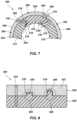
FIG. 7 illustrates a partial transverse cross-sectional view of a sponge liner, according to an embodiment of the present disclosure. -
FIG. 8 illustrates a partial longitudinal plan view of a sponge liner, according to an embodiment of the present disclosure. - The illustrations presented herein are not meant to be actual views of any sponge core barrel, sponge liner, sleeve, or component thereof, but are merely idealized representations that are used to describe embodiments of the disclosure.
- As used herein, directional terms, such as "above"; "below"; "up"; "down"; "upward"; "downward"; "top"; "bottom"; "top-most"; "bottom-most"; "proximal" and "distal" are to be interpreted from a reference point of the object so described as such object is located in a vertical well bore, regardless of the actual orientation of the object so described. For example, the terms "above"; "up"; "upward"; "top"; "top-most" and "proximal" are synonymous with the term "uphole," as such term is understood in the art of subterranean well bore drilling. Similarly, the terms "below"; "down"; "downward"; "bottom"; "bottom-most" and "distal" are synonymous with the term "downhole," as such term is understood in the art of subterranean well bore drilling and coring operations.
- As used herein, the term "longitudinal" refers to a direction parallel to a longitudinal axis of the sponge liner. For example, a "longitudinal" cross-section shall mean a "cross-section viewed in a plane extending along the longitudinal axis of the sponge liner."
- As used herein, the terms "lateral"; "laterally"; "transverse" or "transversely" shall mean "transverse to a longitudinal axis of the sponge liner." For example, a "lateral" or "transverse" cross-section shall mean a "cross-section viewed in a plane transverse to the longitudinal axis of the sponge liner."
-
FIG. 3 illustrates atubular sleeve 100, or "sponge liner tube" or "shell," of a sponge liner according to an embodiment of the present disclosure. The tubular sleeve may comprise aluminum or one or more other materials, such as other metals, alloys, or a polymer composite. Thetubular sleeve 100 may be of substantially cylindrical shape. Additionally, as shown inFIG. 3A , thetubular sleeve 100 may have internal ribs orprotrusions 101, directed either substantially parallel to or slanted or spiraling with respect to the longitudinal axis L of thesleeve 100. In some embodiments, stub-like protrusions 103 may be located on an interior of thesleeve 100. Thetubular sleeve 100 may include a plurality ofslots 102 extending radially through awall 104 of thetubular sleeve 100 from anouter surface 106 of thesleeve 100 to aninner surface 108 of thesleeve 100. Theslots 102 provide thetubular sleeve 100 with increased elasticity in a circumferential direction with respect to a longitudinal axis of thesleeve 100, allowing an annular sponge layer attached to theinner surface 108 of the sleeve 100 (shown inFIGS. 5 and6 ) to maintain contact with a core entering thesleeve 100 while reducing frictional forces between the sponge layer and the core as the core enters the sponge liner. The sponge layer may include any absorptive material known in the art. By way of non-limiting example, the sponge layer may include a polyurethane foam, a felt, a fur, a fabric, a woven structure, or any combination of the foregoing. Theslots 102 may be evenly spaced apart about a circumference of thesleeve 100. For example, as shown inFIG. 3 , thesleeve 100 may include four (4)slots 102, each of which may be spaced apart from thenearest slot 102 by about 90 degrees about the circumference of thesleeve 100. However, in other embodiments, theslots 102 may be unevenly spaced apart about the circumference of thesleeve 100. - The
slots 102 may be formed by a wide variety of processes, including, by way of non-limiting example, cutting, milling, or other methods. Alternatively, thesleeve 100 may be formed to include theslots 102 from the outset by a casting process, such as centrifugal casting, or other methods. - Moreover, while four (4)
slots 102 are shown extending through thewall 104 of thetubular sleeve 100 ofFIG. 3 , it is to be appreciated that fewer or more than four (4) slots may be formed in thewall 104 of thesleeve 100. For example, thesleeve 100 may include as few as one (1)slot 102 formed through thewall 104 thereof. In other embodiments, thesleeve 100 may include six (6)slots 102 formed through thewall 104 thereof. In such an embodiment, the six (6) slots may be spaced apart at about 60 degree intervals about a circumference of thesleeve 100. However, as previously described, the six (6) slots may be spaced apart at uneven intervals about a circumference of the sleeve. In further embodiments, thesleeve 100 may include eight (8) ormore slots 102 formed through thewall 104 thereof. The present disclosure does not contemplate an upper limit to the amount ofslots 102 formed through thewall 104 of thetubular sleeve 100. - Additionally, while the
slots 102 are shown as extending longitudinally along thesleeve 100, in some embodiments theslots 102 may also include portions oriented and extending substantially radially along the circumference of thesleeve 100. In further embodiments, theslots 102 may have longitudinally extending portions or segments, radially extending portions or segments, obliquely extending portions or segments, or irregularly oriented portions or segments. It is to be understood that any pattern or orientation of theslots 102 is within the scope of the present disclosure. - Each of the
slots 102 may include a plurality of slot segments 110 separated by distinct formations of material, or "tabs" 112, of the material of thesleeve 100. For example,slot 102a ofFIG. 3 includes three (3)slot segments tabs slot 102a may be separated from anupper end 114 of thesleeve 100 by atab 112c, while a longitudinally bottom end ofslot 102a may be separated from abottom end 116 of the sleeve 110 by atab 112d.FIG. 3B illustrates a magnified view of atab 112 separating two segments of aslot 102. It is to be appreciated that thetab 112 may be configured as any portion of thesleeve wall 104 located between one segment of aslot 102 and an adjacent segment of the same or adifferent slot 102 or between a segment of theslot 102 and an adjacentupper end 114 orlower end 116 of thesleeve 100. Thetabs 112 may have various shapes and configurations, and are not limited to the design illustrated inFIGS. 3 and 3B , as will be discussed in more detail below. The combination of theslots 102 and thetabs 112 enables thesleeve 100 to exhibit a higher elasticity, particularly in the circumferential direction (which also provides a higher degree of elasticity in the radial direction), while also maintaining thesleeve 100 as a single, integral body. Theslots 102 andtabs 112 may optionally be located and oriented such that, at each longitudinal location of thesleeve 100, thesleeve wall 104 does not extend continuously about the entire circumference of thesleeve 100. - With continued reference to
FIG. 3 , if greater flexibility of thesleeve 100 is required, one or more of thetabs 112 interposed between segments of aslot 102 may be fractured to join segments of theslot 102. Slot 102b ofFIG. 3 is shown having each of thetabs 112 of thewall 104 fractured or otherwise removed, allowing theslot 102b to extend continuously from theupper end 114 of thesleeve 100 to thelower end 116 of thesleeve 100, thus increasing the radial flexibility of thesleeve 100 and, correspondingly, the radial flexibility of a sponge layer attached to the inner surface of thesleeve 100. For illustrative purposes,FIG. 3 showsslot 102a with all thetabs 112 in place andslot 102b with all of thetabs 112 removed or fractured, it is to be understood that this is for illustrative purposes. In practice, a user may fracture or remove selectedtabs 112 from any of theslots 102 in any desired pattern to provide thesleeve 100 with a desired degree of radial elasticity. For example, a user may fracture or remove thetabs 112 of theslots 102 in a manner to provide thesleeve 100 with a uniform degree of increased elasticity in the radial direction.FIG. 3C shows a magnified view of aslot 102 with a tab removed between adjacent slot segments. Thetabs 112 may be removed by fracturing or other methods. Thetabs 112 may be fractured or removed at the drilling site or prior to transfer to the drill site, or the sleeve could be manufactured with a reduced number of tabs in the beginning. The ability to fracture or remove thetabs 112, or to choose from a variety of sleeves with manufactured with different mount of tabs, allows a user to adjust the elasticity of thetubular sleeve 100, and thus the associated sponge liner, to tailor the elasticity of the sponge liner to a particular formation to be cored. For example, prior to coring a formation, a user may remove as many of the tabs as necessary to provide thesleeve 100 with a desired degree of enhanced elasticity in consideration of the parameters of a formation to be cored. To achieve a maximum elasticity of a particular sponge liner of the present disclosure, a user may remove or fracture all of the tabs associated with each of theslots 102. In this manner, as a core 18 moves upward within the sponge liner as the coring tool progresses downward into the formation, an annular sponge layer attached to theinner surface 108 of thesleeve 100 may remain in contact with the core 18 while also exerting a decreased amount of friction on thecore 18 by virtue of the elasticity of thesleeve 100 provided by the arrangement of theslots 102 andtabs 112 therein. Moreover, the increased elasticity of thesleeve 100, configured as disclosed herein, allows one or both of the sleeve and the sponge layer to have an inner diameter smaller than that of a sponge layer of a prior art sponge liner without a corresponding increased risk of damage to the core 18 caused as a result of friction between the core 18 and the sponge layer. It is to be appreciated that the elasticity of thesleeve 100 may also be increased by forming thesleeve 100 to have a fewer number oftabs 112 interposed between slot segments. - The
slots 102 andtabs 112 of thesleeve 100 may be configured such that removing or fracturing some or all of thetabs 112 to increase the radial elasticity of thesleeve 100 substantially does not affect the elasticity or rigidity of thesleeve 100 in the longitudinal direction. In this manner, a user may remove or fracturecertain tabs 112 to provide thesleeve 100 with a desired degree of radial elasticity (to accommodate a certain formation to be cored) while not affecting the longitudinal elasticity of thesleeve 100, and thus not compromising the rigidity of thesleeve 100 in the longitudinal direction. - In other embodiments, increased radial elasticity of the
sleeve 100 may be provided by a one or more link arrangements formed in thesleeve 100.FIG. 4 illustrates a view of asingle link arrangement 118 formed in thesleeve 100, however, it is to be appreciated that eachslot 102 of thesleeve 100 may include a plurality oflink arrangements 118 interposed between slot segments 110, similarly as described above in relation to thetabs 112 shown inFIG. 3 . As shown inFIG. 4 , aslot 102 may extend longitudinally through thewall 104 of thesleeve 100 in a direction from theupper end 114 of thesleeve 100 to thelower end 116 of thesleeve 100, substantially separating a firstcircumferential section 120a of thesleeve 100 from a secondcircumferential section 120b of thesleeve 100 located on opposite circumferential sides of theslot 102. Thelink arrangement 118 may connect the firstcircumferential section 120a and the secondcircumferential section 120b of thesleeve 100. - The
slot 102 may include at least two (2) segments, such as an upper segment 1 10d and a lower segment 1 10e, separated from one another by a formation of material of thewall 104 of thesleeve 100. A forkedlower portion 122 of the upper slot segment 1 10d may branch out and includeslot branches upper end portion 124 of thelower slot segment 110e, wherein theslot branches lower portion 122 of theupper slot segment 110d and theupper portion 124 of thelower slot segment 110e. Thelink arrangement 118 may include a portion of material of thesleeve wall 104 extending circumferentially and longitudinally between the forkedlower portion 122 of theupper slot segment 110d and theupper potion 124 of thelower slot segment 110e. For example, as shown inFIG. 4 , thelink arrangement 118 may include awall portion 126 extending longitudinally between anupper end 128 of thelower slot segment 110e and alower base portion 130 of the forkedlower portion 122 of theupper slot segment 110d. Thelink arrangement 118 may also include a firstlongitudinal wall portion 132 extending parallel with and circumferentially between theupper portion 124 of thelower slot segment 110e and one of theslot branches 110f of the forkedlower portion 122 of the upper slot segment 1 10d on a first circumferential side of thelower slot segment 110e. Thelink arrangement 118 may also include a secondlongitudinal wall portion 134 extending parallel with and circumferentially between theupper portion 124 of thelower slot segment 110e and the other of thebranches 110g of the forkedlower portion 122 of theupper slot segment 110d on a second circumferential side of thelower slot segment 110e opposite the first circumferential side. Each of the first and secondlongitudinal wall portions link arrangement 118 may extend a length D1 from thelower base portion 130 of theupper slot segment 110d to thelower end branch portion lower portion 122 of theupper slot segment 110d. WhileFIG. 4 illustrates that each of the first and secondlongitudinal wall portions link arrangement 118 have the same length D1, it is to be appreciated that the first and secondlongitudinal wall portions link arrangement 118 may have differing lengths, as determined by the longitudinal lengths of the slot branches 1 10f, 110g. - The length Di and circumferential width of each of the first and second
longitudinal wall portions slot segments slot branches upper slot segment 110d, may each be sized and configured to provide thesleeve 100 with a predetermined degree of radial elasticity. It is to be appreciated that the link arrangement ofFIG. 4 embodies onepossible link arrangement 118 design, while other link arrangement designs are also within the scope of the present disclosure. Other non-limiting examples of link arrangements are shown inFIG 4A through 4D , which may include fewer than or more than two longitudinal wall portions, similar to thewall portions FIG. 4 . Additionally, thewall portions 132 ofFIGS. 4A through 4D may vary in length D1, orientation and shape from those shown inFIG. 4 . - Additionally, it is also to be appreciated that link arrangements, such as the
link arrangement 118 ofFIG. 4 , may be used in combination with thetabs 112 described in reference toFIG. 3 to provide thesleeve 100 with an overall adjustable radial elasticity. Moreover, the radial elasticity of thesleeve 100 may be further increased by removing or fracturing portions of thelink arrangements 118. -
FIG. 5 illustrates an example beyond the wording of the claims of thesleeve 100 separated into four (4)circumferential sections 140 separated by four (4)slots 102 formed through thewall 104 of thesleeve 100 and extending from theupper end 114 of thesleeve 100 to thelower end 116 of thesleeve 100. Accordingly, eachcircumferential sleeve section 140 includes a portion of each of the upper and lower ends 114, 116 of thesleeve 100 and extends substantially continuously from theupper end 114 to thelower end 116 of thesleeve 100. In such an example, thetubular sleeve 100 is not a single integral sleeve, but comprises separate, mutually adjacentcircumferential sleeve sections 140. Theslots 102 may be substantially parallel to the sleeve axis, as shown inFIG. 5 , or may follow any direction along the length of the sleeve, as shown inFIG. 6 . With continued reference toFIG. 5 , thesleeve 100 may include afirst sleeve section 140a, asecond sleeve section 140b, athird sleeve section 140c, and afourth sleeve section 140d. Anannular sponge layer 142 may be attached to the inner surface of each of thesleeve sections FIG. 5 illustrates thetubular sleeve 100 formed of four (4)sleeve sections sleeve 100 may comprise fewer or more than four (4) sleeve sections. For example, thesleeve 100 may include as few as two (2)sleeve sections 140. In other examples, thesleeve 100 may include five (5)sleeve sections 140. In further examples, thesleeve 100 may include eight (8) ormore sleeve sections 140. The present disclosure does not contemplate an upper limit to the amount ofsleeve sections 140 forming thetubular sleeve 100 of the sponge liner. - With continued reference to
FIG. 5 , in addition to having thesponge layer 142 attached to aninner surface 108 thereof, thesleeve sections 140 may be further coupled together by a plurality of external wire springs 144 extending circumferentially around thesleeve 100. The external wire springs 144 may be located within and extend through circumferential grooves orchannels 146 formed in theouter surface 106 of thesleeve sections 140. While thesleeve 100 shown inFIG. 5 is configured to include three (3) external wire springs 144 extending circumferentially around thesleeve 100 to further couple thesleeve sections 140 together, only two (2) of the external wire springs 144 are shown, while acircumferential channel 146 having noexternal wire spring 144 therein is shown for illustrative purposes. It is to be appreciated that thesleeve 100 ofFIG. 5 may be configured to accommodate more or less than three (3) external wire springs 144. For example, in some embodiments, asleeve 100, such as the one shown inFIG. 5 , may have as few as onecircumferential channel 146 formed in theouter surfaces 106 of thesleeve sections 140 for housing a singleexternal wire spring 144. In other examples, thesleeve 100 may have five (5)circumferential channels 146 formed in theouter surfaces 106 of thesleeve sections 140 for housing five (5) external wire springs 144. In further examples, thesleeve 100 may have eight (8)circumferential channels 146 formed in theouter surfaces 106 of thesleeve sections 140 for housing eight (8) external wire springs 144. In yet other examples, thesleeve 100 may have ten (10) or morecircumferential channels 146 formed in theouter surfaces 106 of each of thesleeve sections 140 for housing ten (10) or more external wire springs 144. Of course, springs of other materials and shape, such as elastomeric springs or rings, may also be employed. In other examples, other elastic elements could be used to couple thesleeve sections 140. For example, such elastic elements may comprise one or more of a mesh, a fabric, a hose, or other elastic structures. - It is also to be appreciated that the
sleeve sections 140 may be coupled together by other fastening devices, including clamps, screws, bolts, or other mechanical fasteners. Such mechanical fasteners may be fractured or uncoupled, in a similar manner as previously described, prior to a coring run to provide thesleeve 100 with greater elasticity if so desired. In other examples, thesleeve sections 140 may be coupled by an elastic material, such as a silicone or other polymer, located in the slots betweenadjacent sleeve sections 140 and adhering to side walls of theadjacent sleeve sections 140 in a manner to elastically bond thesleeve sections 140 together. Other fastening means for elastically coupling thesleeve sections 140 together are also within the scope of the present disclosure. - In other examples, as shown in
FIG. 6 , thesponge layer 142 may be formed to extend radially outwardly into and within theslots 102 and to adhere to side walls of adj acentsleeve sections 140 as well as to inner surfaces of thesleeve sections 140. In this manner, each of thesleeve sections 140 may be coupled to thesponge layer 142 at theinner surfaces 108 and side walls of each of the sleeve sections. In such examples, the overall integrity of thesleeve 100 may be maintained by thesleeve sections 140 and thesponge layer 142 without the need for any additional fastening mechanism or means for coupling thesleeve sections 140 together. In yet other examples, as shown inFIG. 6A , thesponge layer 142 may not extend into and within theslots 102 or adhere to the side walls of thesleeve sections 140. In such examples, thesponge layer 142 links thesleeve sections 140 together. In other examples, thesponge layer 142 may extend partially into and within theslots 102 and may adhere to portions of the side walls of thesleeve sections 140 to which thesponge layer 142 is in contact. The increased circumferential elasticity in examples as described in this paragraph may result from the elasticity of the sponge material coupling thesleeve sections 140. - In other embodiments, as shown in
FIG. 7 and FIG. 8 , aliner 200 may be constructed of a multitude ofindividual segments 202, which are combined to cover a substantially full circumference. Individualliner sleeve segments 204 may have overlappingareas 206 in a circumferential direction, to maintain a substantially cylindrical outer shape of theliner 200, while allowing a change in the circumference. For example, the individualliner sleeve segments 204 may each have aprotrusion 208 extending within arecess 210 of an adjacentliner sleeve segment 204 to form the overlappingareas 206. These overlappingareas 206 in may extend in longitudinal direction over only a portion or over the entirety of the longitudinal length of theliner 200. For example, as shown inFIG. 8 , theprotrusions 208 and associatedrecesses 210 of theliner sleeve segments 204 may be located at distinct longitudinal positions of theliner 200 and may be squared, rounded, or shaped according to any of various other shapes. Portions of the overlappingareas 206 may be configured to substantially maintain theliner sleeve segments 204 mutually at the same longitudinal location. Additionally, theprotrusions 208 may transmit forces to therecesses 210 in a direction substantially parallel to the longitudinal axis L of theliner 200. Referring again toFIG. 7 , associatedabsorptive layers 212 of theliner segments 202 may also haveareas 214 overlapping in a circumferential direction. For example, theabsorptive layer segments 212 may each have aprotrusion 216 extending within arecess 218 of an adjacentabsorptive layer segment 212. As with theliner sleeve segments 204 shown inFIG. 8 , theprotrusions 216 and associatedrecesses 218 of theabsorptive layer segments 212 may be located at distinct longitudinal positions of theliner 200 and may have various shapes and configurations. These overlappingareas liner sleeve segments 204 and theabsorptive layer segments 212 may ensure that there is no open fluid passage from aninner surface 220 of theliner 200 towards anouter periphery 222 of theliner 200, where the formation fluid of interest may become lost for further analysis. Additionally, theprotrusions 216 may transmit forces to therecesses 218 in a direction substantially parallel to the longitudinal axis L of theliner 200. As shown inFIG. 8 , theindividual liner segments 202 may be held together by elastic elements (not shown) located incircumferential grooves 224 formed in theouter periphery 214 of theliner sleeve segments 204, as previously described, by way of non-limiting example. - The scope of the invention is defined by the features specified in the appended claims.
Claims (8)
- A liner tube for a core barrel assembly, comprising:
a sleeve (100) having an inner surface (108) configured to be coupled to a layer of material (142) configured to absorb or adsorb formation fluids or parts of formation fluids, the sleeve (100) being substantially cylindrical, wherein, at every longitudinal location of the sleeve with respect to a longitudinal axis of the sleeve, a transverse cross-section of a wall of the sleeve includes at least one gap (102) extending radially through the entire wall of the sleeve (100), the at least one gap (102) separating a portion (120a) of the sleeve wall on one circumferential side of the at least one gap (102) from another portion (120b) of the sleeve wall on an opposite circumferential side of the at least one gap (102), and the sleeve (100) having a flexibility in a circumferential direction greater than that of a sleeve (100) without a gap (102) extending radially through an entire wall of the sleeve (100) at a transverse cross-section of the sleeve (100) at every longitudinal location of the sleeve (100);
wherein the at least one gap (102) comprises at least one slot (102) formed in an outer surface of the sleeve (100), each slot (102) extending completely radially through a wall of the sleeve (100) from an outer surface (106) of the sleeve (100) to the inner surface (108) of the sleeve (100), at least a portion of the slot (102) extending longitudinally discontinuously along at least a portion of an entire length of the sleeve (100), wherein the slot (102) comprises a plurality of segments (110), and one or more formations of material of the wall of the sleeve (100) separate the segments (110) of the slot (102). - The liner tube of claim 1, wherein the plurality of segments (110) includes at least a first slot segment (110) and a second slot segment (110), the first slot segment (110) having a portion circumferentially offset from and longitudinally coextensive with a portion of the second slot segment (110), a portion of the wall of the sleeve (100) located circumferentially between and coextensive with the portion of the first slot segment (110) and the portion of the second slot segment (110).
- The liner tube of claim 1, wherein the slot (102) extends longitudinally along the entire length of the sleeve (100).
- The liner tube of claim 1, wherein the at least one slot comprises three or more slots (102) circumferentially separated from one another about a circumference of the sleeve (100).
- The liner tube of claim 4, wherein the three or more slots (102) are circumferentially symmetrically located about a circumference of the sleeve (100).
- The liner tube of claim 1, further comprising the layer of material (142) coupled to an inner surface (108) of the sleeve (100).
- The liner tube of claim 6, wherein the layer of material (142) has a portion extending radially outward into and at least partially within the at least one gap (102).
- A method of building a coring tool having the liner tube of claim 1, the method comprising:
locating the sleeve (100) in a core barrel assembly.
Applications Claiming Priority (2)
| Application Number | Priority Date | Filing Date | Title |
|---|---|---|---|
| US201562120707P | 2015-02-25 | 2015-02-25 | |
| PCT/US2016/019581 WO2016138276A1 (en) | 2015-02-25 | 2016-02-25 | Sponge liner sleeves for a core barrel assembly, sponge liners and related methods |
Publications (3)
| Publication Number | Publication Date |
|---|---|
| EP3262274A1 EP3262274A1 (en) | 2018-01-03 |
| EP3262274A4 EP3262274A4 (en) | 2019-02-27 |
| EP3262274B1 true EP3262274B1 (en) | 2024-09-25 |
Family
ID=56692980
Family Applications (1)
| Application Number | Title | Priority Date | Filing Date |
|---|---|---|---|
| EP16756367.5A Active EP3262274B1 (en) | 2015-02-25 | 2016-02-25 | Sponge liner sleeves for a core barrel assembly, sponge liners and related methods |
Country Status (4)
| Country | Link |
|---|---|
| US (1) | US10072471B2 (en) |
| EP (1) | EP3262274B1 (en) |
| SA (1) | SA517382156B1 (en) |
| WO (1) | WO2016138276A1 (en) |
Families Citing this family (6)
| Publication number | Priority date | Publication date | Assignee | Title |
|---|---|---|---|---|
| US10072471B2 (en) * | 2015-02-25 | 2018-09-11 | Baker Hughes Incorporated | Sponge liner sleeves for a core barrel assembly, sponge liners and related methods |
| US10975644B2 (en) * | 2016-12-06 | 2021-04-13 | Halliburton Energy Services, Inc. | Inner barrel assembly for recovery of reservoir fluids from a core sample |
| CN108252669B (en) * | 2018-02-07 | 2023-09-19 | 中国石油天然气集团有限公司 | Combined type core discharging device |
| CN109366594B (en) * | 2018-12-13 | 2024-02-13 | 佛山科学技术学院 | Roll paper cutting roller |
| CN114645682A (en) * | 2020-12-19 | 2022-06-21 | 中国石油化工集团有限公司 | Sponge coring tool and sponge coring process |
| CN116927691A (en) * | 2022-03-29 | 2023-10-24 | 中石化石油工程技术服务有限公司 | Preparation method of core-taking sponge lining cylinder and hydrophobic oil-absorbing sponge |
Citations (2)
| Publication number | Priority date | Publication date | Assignee | Title |
|---|---|---|---|---|
| US3328068A (en) * | 1965-11-15 | 1967-06-27 | Joint Coal Board | Lifter for rotary core drills |
| US3874465A (en) * | 1973-10-02 | 1975-04-01 | Randolph Co | Coring apparatus |
Family Cites Families (60)
| Publication number | Priority date | Publication date | Assignee | Title |
|---|---|---|---|---|
| US1867720A (en) | 1928-04-06 | 1932-07-19 | Hughes Tool Co | Vent for core drills |
| US1857693A (en) | 1929-10-07 | 1932-05-10 | Harry J Quintrell | Core barrel having core receptacle |
| US2019176A (en) | 1932-05-07 | 1935-10-29 | Redus D Dodds | Sample taking device |
| US2596832A (en) | 1949-03-07 | 1952-05-13 | Jr Edward B Williams | Core barrel |
| US2747841A (en) | 1951-09-08 | 1956-05-29 | Adamson William Murdoch | Core-lifting means for rotary drills |
| US2876996A (en) * | 1955-05-05 | 1959-03-10 | Jersey Prod Res Co | Core barrel |
| US2789790A (en) | 1956-06-13 | 1957-04-23 | Ii John H Kirby | Core drilling apparatus |
| US3012622A (en) | 1959-04-20 | 1961-12-12 | Christensen Diamond Prod Co | Core barrel apparatus |
| GB1100962A (en) * | 1964-05-12 | 1968-01-31 | Boyles Bros Drilling Company L | Improvements in and relating to core barrel apparatus for deep drilling |
| NL155947B (en) | 1965-04-14 | 1978-02-15 | Stichting Waterbouwkundig Lab | METHOD AND EQUIPMENT FOR THE CUTTING OF AN UNSTROUGHED SOIL SAMPLE. |
| US3804184A (en) | 1973-03-08 | 1974-04-16 | M Gusman | Core drilling apparatus |
| US3986555A (en) | 1975-04-10 | 1976-10-19 | Dresser Industries, Inc. | Apparatus for providing a packaged core |
| US4142594A (en) | 1977-07-06 | 1979-03-06 | American Coldset Corporation | Method and core barrel apparatus for obtaining and retrieving subterranean formation samples |
| GB2000824B (en) | 1977-07-06 | 1982-05-19 | American Coldset Corp | Method and core barrel apparatus for obtaining and retrieving subterranean formation samples |
| US4230192A (en) | 1978-08-08 | 1980-10-28 | Pfannkuche Fritz T | Core sampling apparatus and method |
| US4256192A (en) | 1979-07-06 | 1981-03-17 | Christensen, Inc. | Pressure core barrel |
| US4312414A (en) * | 1980-05-23 | 1982-01-26 | Diamond Oil Well Drilling Company | Method and apparatus for obtaining saturation data from subterranean formations |
| US4449594A (en) | 1982-07-30 | 1984-05-22 | Allied Corporation | Method for obtaining pressurized core samples from underpressurized reservoirs |
| US4598777A (en) | 1983-07-13 | 1986-07-08 | Diamond Oil Well Drilling Company | Method and apparatus for preventing contamination of a coring sponge |
| US4502553A (en) * | 1983-07-13 | 1985-03-05 | Diamond Oil Well Drilling | Sponge coring apparatus with reinforced sponge |
| US4479557A (en) | 1983-07-13 | 1984-10-30 | Diamond Oil Well Drilling Co. | Method and apparatus for reducing field filter cake on sponge cores |
| US4553613A (en) | 1983-09-09 | 1985-11-19 | Norton Christensen, Inc. | Hydraulic lift inner barrel in a drill string coring tool |
| US4552229A (en) | 1983-09-09 | 1985-11-12 | Norton Christensen, Inc. | Externally powered core catcher |
| US4566545A (en) | 1983-09-29 | 1986-01-28 | Norton Christensen, Inc. | Coring device with an improved core sleeve and anti-gripping collar with a collective core catcher |
| US4580643A (en) | 1984-09-10 | 1986-04-08 | Norton Christensen, Inc. | Adjustable bearing section core barrel |
| US4638872A (en) | 1985-04-01 | 1987-01-27 | Diamond Oil Well Drilling Company | Core monitoring device |
| US4664205A (en) | 1985-04-11 | 1987-05-12 | Norton Christensen, Inc. | Hydraulic inner barrel in a drill string coring tool |
| CA1279864C (en) | 1985-12-27 | 1991-02-05 | Rocco Difoggio | Method for determining the amount of oil in a sponge core |
| US4716974A (en) | 1986-07-21 | 1988-01-05 | Eastman Christensen Co | Method and apparatus for coring with an in situ core barrel sponge |
| US4930587A (en) | 1989-04-25 | 1990-06-05 | Diamant Boart-Stratabit (Usa) Inc. | Coring tool |
| US5042598A (en) | 1990-06-18 | 1991-08-27 | Sherman Johnny C | Drilling fluid additive sweep cartridge and method |
| US5107942A (en) | 1991-04-04 | 1992-04-28 | Baker Hughes Incorporated | Inner tube stabilizer for a corebarrel |
| US5253720A (en) | 1991-06-13 | 1993-10-19 | Energy Ventures, Inc. | Method and apparatus for taking an undisturbed core sample |
| US5255751A (en) | 1991-11-07 | 1993-10-26 | Huey Stogner | Oilfield make-up and breakout tool for top drive drilling systems |
| US5360074A (en) | 1993-04-21 | 1994-11-01 | Baker Hughes, Incorporated | Method and composition for preserving core sample integrity using an encapsulating material |
| US5482123A (en) | 1993-04-21 | 1996-01-09 | Baker Hughes Incorporated | Method and apparatus for pressure coring with non-invading gel |
| US5568838A (en) | 1994-09-23 | 1996-10-29 | Baker Hughes Incorporated | Bit-stabilized combination coring and drilling system |
| US5439065A (en) | 1994-09-28 | 1995-08-08 | Western Atlas International, Inc. | Rotary sidewall sponge coring apparatus |
| US5546798A (en) | 1995-05-12 | 1996-08-20 | Baker Hughes Incorporated | Method and composition for preserving core sample integrity using a water soluble encapsulating material |
| BE1009968A5 (en) | 1996-01-15 | 1997-11-04 | Dresser Ind | Core core and method for its implementation. |
| BE1009965A3 (en) | 1996-01-15 | 1997-11-04 | Baroid Technology Inc | Core. |
| US5881825A (en) | 1997-01-08 | 1999-03-16 | Baker Hughes Incorporated | Method for preserving core sample integrity |
| US6009960A (en) | 1998-01-27 | 2000-01-04 | Diamond Products International, Inc. | Coring tool |
| US6216804B1 (en) | 1998-07-29 | 2001-04-17 | James T. Aumann | Apparatus for recovering core samples under pressure |
| US6719070B1 (en) * | 2000-11-14 | 2004-04-13 | Baker Hughes Incorporated | Apparatus and methods for sponge coring |
| JP3434800B2 (en) | 2001-01-31 | 2003-08-11 | 海洋科学技術センター | Crust core sample collection method, and antibacterial polymer gel and gel material used for the method |
| US7347281B2 (en) | 2004-08-18 | 2008-03-25 | Baker Hughes Incorporated | Coring tubular and method for reducing contamination and processing speed of a core sample |
| GB0618798D0 (en) * | 2006-09-23 | 2006-11-01 | Corpro Systems Ltd | Container and method |
| WO2011011837A1 (en) | 2009-07-31 | 2011-02-03 | Halliburton Energy Services, Inc. | Inner tube of a core barrel |
| US8689903B2 (en) | 2010-04-14 | 2014-04-08 | Baker Hughes Incorporated | Coring apparatus and methods |
| CA2828486C (en) * | 2011-02-28 | 2015-09-29 | Neil H. Akkerman | Disconnect assembly for cylindrical members |
| US8453766B2 (en) | 2011-08-12 | 2013-06-04 | Intevep, S.A. | Hydrocarbon formation core protection and transportation apparatus |
| US9217306B2 (en) * | 2011-10-03 | 2015-12-22 | National Oilwell Varco L.P. | Methods and apparatus for coring |
| US9765585B2 (en) | 2013-07-18 | 2017-09-19 | Baker Hughes Incorporated | Coring tools and methods for making coring tools and procuring core samples |
| US9926756B2 (en) | 2013-07-18 | 2018-03-27 | Baker Hughes Incorporated | Pressure compensation modules for coring tools, coring tools including pressure compensation modules, and related methods |
| WO2015031475A1 (en) | 2013-08-27 | 2015-03-05 | Baker Hughes Incorporated | Mechanical core jam indicator for coring tools, coring tools including such core jam indicators, and related methods |
| EP3042028B1 (en) | 2013-09-06 | 2018-11-14 | Baker Hughes, a GE company, LLC | Coring tools including core sample flap catcher and related methods |
| US9540896B2 (en) * | 2014-04-01 | 2017-01-10 | National Oilwell Varco, L.P. | Frangible core barrel |
| US10072471B2 (en) * | 2015-02-25 | 2018-09-11 | Baker Hughes Incorporated | Sponge liner sleeves for a core barrel assembly, sponge liners and related methods |
| US10125553B2 (en) * | 2015-03-06 | 2018-11-13 | Baker Hughes Incorporated | Coring tools for managing hydraulic properties of drilling fluid and related methods |
-
2016
- 2016-02-22 US US15/050,186 patent/US10072471B2/en active Active
- 2016-02-25 WO PCT/US2016/019581 patent/WO2016138276A1/en not_active Ceased
- 2016-02-25 EP EP16756367.5A patent/EP3262274B1/en active Active
-
2017
- 2017-08-17 SA SA517382156A patent/SA517382156B1/en unknown
Patent Citations (2)
| Publication number | Priority date | Publication date | Assignee | Title |
|---|---|---|---|---|
| US3328068A (en) * | 1965-11-15 | 1967-06-27 | Joint Coal Board | Lifter for rotary core drills |
| US3874465A (en) * | 1973-10-02 | 1975-04-01 | Randolph Co | Coring apparatus |
Also Published As
| Publication number | Publication date |
|---|---|
| WO2016138276A1 (en) | 2016-09-01 |
| US10072471B2 (en) | 2018-09-11 |
| US20160245030A1 (en) | 2016-08-25 |
| EP3262274A1 (en) | 2018-01-03 |
| EP3262274A4 (en) | 2019-02-27 |
| SA517382156B1 (en) | 2023-01-31 |
Similar Documents
| Publication | Publication Date | Title |
|---|---|---|
| US10072471B2 (en) | Sponge liner sleeves for a core barrel assembly, sponge liners and related methods | |
| US12331598B2 (en) | Wireline standoff | |
| EP2917479B1 (en) | Universal downhole probe system | |
| US7836978B2 (en) | Cutting elements for casing component drill out and subterranean drilling, earth boring drag bits and tools including same and methods of use | |
| US20200157904A1 (en) | Automatic driller | |
| US9234394B2 (en) | Low friction wireline standoff | |
| US8286697B2 (en) | Internally supported perforating gun body for high pressure operations | |
| US20020139537A1 (en) | Method for enabling movement of a centralized pipe through a reduced diameter restriction and apparatus therefor | |
| US20150068728A1 (en) | Downhole Tool Having Slip Composed of Composite Ring | |
| WO2016153831A1 (en) | Transverse sidewall coring | |
| US10125550B2 (en) | Orientation of cutting element at first radial position to cut core | |
| US20020139538A1 (en) | Method for enabling movement of a centralized pipe through a reduced diameter restriction and apparatus therefor | |
| RU2664564C2 (en) | Fragile inner core-receiver | |
| CA2946497A1 (en) | Downhole drilling assembly with concentric alignment feature | |
| US10301881B2 (en) | Fixed cutter drill bit with multiple cutting elements at first radial position to cut core | |
| CA2893467A1 (en) | Methods and apparatus for downhole probes | |
| EP2815059B1 (en) | Downhole tool and method | |
| CA2914545C (en) | Mud motor with integrated reamer | |
| US20140182937A1 (en) | Roller cone drill bit | |
| WO2015004203A1 (en) | System for drilling a borehole and use thereof | |
| WO2023193167A1 (en) | An impact transmission mechanism for a rotary percussion drilling tool | |
| US20140318817A1 (en) | Probe Packer and Method of Using Same |
Legal Events
| Date | Code | Title | Description |
|---|---|---|---|
| STAA | Information on the status of an ep patent application or granted ep patent |
Free format text: STATUS: THE INTERNATIONAL PUBLICATION HAS BEEN MADE |
|
| PUAI | Public reference made under article 153(3) epc to a published international application that has entered the european phase |
Free format text: ORIGINAL CODE: 0009012 |
|
| STAA | Information on the status of an ep patent application or granted ep patent |
Free format text: STATUS: REQUEST FOR EXAMINATION WAS MADE |
|
| 17P | Request for examination filed |
Effective date: 20170919 |
|
| AK | Designated contracting states |
Kind code of ref document: A1 Designated state(s): AL AT BE BG CH CY CZ DE DK EE ES FI FR GB GR HR HU IE IS IT LI LT LU LV MC MK MT NL NO PL PT RO RS SE SI SK SM TR |
|
| AX | Request for extension of the european patent |
Extension state: BA ME |
|
| DAV | Request for validation of the european patent (deleted) | ||
| DAX | Request for extension of the european patent (deleted) | ||
| A4 | Supplementary search report drawn up and despatched |
Effective date: 20190129 |
|
| RIC1 | Information provided on ipc code assigned before grant |
Ipc: E21B 25/04 20060101ALI20190123BHEP Ipc: E21B 25/06 20060101ALI20190123BHEP Ipc: E21B 25/02 20060101AFI20190123BHEP Ipc: E21B 10/02 20060101ALI20190123BHEP Ipc: E21B 49/02 20060101ALI20190123BHEP |
|
| STAA | Information on the status of an ep patent application or granted ep patent |
Free format text: STATUS: EXAMINATION IS IN PROGRESS |
|
| 17Q | First examination report despatched |
Effective date: 20190912 |
|
| P01 | Opt-out of the competence of the unified patent court (upc) registered |
Effective date: 20230526 |
|
| GRAP | Despatch of communication of intention to grant a patent |
Free format text: ORIGINAL CODE: EPIDOSNIGR1 |
|
| STAA | Information on the status of an ep patent application or granted ep patent |
Free format text: STATUS: GRANT OF PATENT IS INTENDED |
|
| INTG | Intention to grant announced |
Effective date: 20240405 |
|
| GRAS | Grant fee paid |
Free format text: ORIGINAL CODE: EPIDOSNIGR3 |
|
| GRAA | (expected) grant |
Free format text: ORIGINAL CODE: 0009210 |
|
| STAA | Information on the status of an ep patent application or granted ep patent |
Free format text: STATUS: THE PATENT HAS BEEN GRANTED |
|
| RAP3 | Party data changed (applicant data changed or rights of an application transferred) |
Owner name: BAKER HUGHES HOLDINGS LLC |
|
| AK | Designated contracting states |
Kind code of ref document: B1 Designated state(s): AL AT BE BG CH CY CZ DE DK EE ES FI FR GB GR HR HU IE IS IT LI LT LU LV MC MK MT NL NO PL PT RO RS SE SI SK SM TR |
|
| REG | Reference to a national code |
Ref country code: GB Ref legal event code: FG4D |
|
| REG | Reference to a national code |
Ref country code: CH Ref legal event code: EP |
|
| REG | Reference to a national code |
Ref country code: DE Ref legal event code: R096 Ref document number: 602016089554 Country of ref document: DE |
|
| REG | Reference to a national code |
Ref country code: IE Ref legal event code: FG4D |
|
| REG | Reference to a national code |
Ref country code: LT Ref legal event code: MG9D |
|
| PG25 | Lapsed in a contracting state [announced via postgrant information from national office to epo] |
Ref country code: GR Free format text: LAPSE BECAUSE OF FAILURE TO SUBMIT A TRANSLATION OF THE DESCRIPTION OR TO PAY THE FEE WITHIN THE PRESCRIBED TIME-LIMIT Effective date: 20241226 Ref country code: FI Free format text: LAPSE BECAUSE OF FAILURE TO SUBMIT A TRANSLATION OF THE DESCRIPTION OR TO PAY THE FEE WITHIN THE PRESCRIBED TIME-LIMIT Effective date: 20240925 |
|
| PG25 | Lapsed in a contracting state [announced via postgrant information from national office to epo] |
Ref country code: BG Free format text: LAPSE BECAUSE OF FAILURE TO SUBMIT A TRANSLATION OF THE DESCRIPTION OR TO PAY THE FEE WITHIN THE PRESCRIBED TIME-LIMIT Effective date: 20240925 |
|
| PG25 | Lapsed in a contracting state [announced via postgrant information from national office to epo] |
Ref country code: LV Free format text: LAPSE BECAUSE OF FAILURE TO SUBMIT A TRANSLATION OF THE DESCRIPTION OR TO PAY THE FEE WITHIN THE PRESCRIBED TIME-LIMIT Effective date: 20240925 |
|
| PG25 | Lapsed in a contracting state [announced via postgrant information from national office to epo] |
Ref country code: RS Free format text: LAPSE BECAUSE OF FAILURE TO SUBMIT A TRANSLATION OF THE DESCRIPTION OR TO PAY THE FEE WITHIN THE PRESCRIBED TIME-LIMIT Effective date: 20241225 |
|
| REG | Reference to a national code |
Ref country code: NL Ref legal event code: MP Effective date: 20240925 |
|
| PG25 | Lapsed in a contracting state [announced via postgrant information from national office to epo] |
Ref country code: RS Free format text: LAPSE BECAUSE OF FAILURE TO SUBMIT A TRANSLATION OF THE DESCRIPTION OR TO PAY THE FEE WITHIN THE PRESCRIBED TIME-LIMIT Effective date: 20241225 Ref country code: LV Free format text: LAPSE BECAUSE OF FAILURE TO SUBMIT A TRANSLATION OF THE DESCRIPTION OR TO PAY THE FEE WITHIN THE PRESCRIBED TIME-LIMIT Effective date: 20240925 Ref country code: GR Free format text: LAPSE BECAUSE OF FAILURE TO SUBMIT A TRANSLATION OF THE DESCRIPTION OR TO PAY THE FEE WITHIN THE PRESCRIBED TIME-LIMIT Effective date: 20241226 Ref country code: FI Free format text: LAPSE BECAUSE OF FAILURE TO SUBMIT A TRANSLATION OF THE DESCRIPTION OR TO PAY THE FEE WITHIN THE PRESCRIBED TIME-LIMIT Effective date: 20240925 Ref country code: BG Free format text: LAPSE BECAUSE OF FAILURE TO SUBMIT A TRANSLATION OF THE DESCRIPTION OR TO PAY THE FEE WITHIN THE PRESCRIBED TIME-LIMIT Effective date: 20240925 |
|
| REG | Reference to a national code |
Ref country code: AT Ref legal event code: MK05 Ref document number: 1726772 Country of ref document: AT Kind code of ref document: T Effective date: 20240925 |
|
| PG25 | Lapsed in a contracting state [announced via postgrant information from national office to epo] |
Ref country code: NL Free format text: LAPSE BECAUSE OF FAILURE TO SUBMIT A TRANSLATION OF THE DESCRIPTION OR TO PAY THE FEE WITHIN THE PRESCRIBED TIME-LIMIT Effective date: 20240925 |
|
| PG25 | Lapsed in a contracting state [announced via postgrant information from national office to epo] |
Ref country code: IS Free format text: LAPSE BECAUSE OF FAILURE TO SUBMIT A TRANSLATION OF THE DESCRIPTION OR TO PAY THE FEE WITHIN THE PRESCRIBED TIME-LIMIT Effective date: 20250125 Ref country code: PT Free format text: LAPSE BECAUSE OF FAILURE TO SUBMIT A TRANSLATION OF THE DESCRIPTION OR TO PAY THE FEE WITHIN THE PRESCRIBED TIME-LIMIT Effective date: 20250127 |
|
| PG25 | Lapsed in a contracting state [announced via postgrant information from national office to epo] |
Ref country code: RO Free format text: LAPSE BECAUSE OF FAILURE TO SUBMIT A TRANSLATION OF THE DESCRIPTION OR TO PAY THE FEE WITHIN THE PRESCRIBED TIME-LIMIT Effective date: 20240925 Ref country code: SM Free format text: LAPSE BECAUSE OF FAILURE TO SUBMIT A TRANSLATION OF THE DESCRIPTION OR TO PAY THE FEE WITHIN THE PRESCRIBED TIME-LIMIT Effective date: 20240925 |
|
| PG25 | Lapsed in a contracting state [announced via postgrant information from national office to epo] |
Ref country code: ES Free format text: LAPSE BECAUSE OF FAILURE TO SUBMIT A TRANSLATION OF THE DESCRIPTION OR TO PAY THE FEE WITHIN THE PRESCRIBED TIME-LIMIT Effective date: 20240925 |
|
| PG25 | Lapsed in a contracting state [announced via postgrant information from national office to epo] |
Ref country code: EE Free format text: LAPSE BECAUSE OF FAILURE TO SUBMIT A TRANSLATION OF THE DESCRIPTION OR TO PAY THE FEE WITHIN THE PRESCRIBED TIME-LIMIT Effective date: 20240925 Ref country code: AT Free format text: LAPSE BECAUSE OF FAILURE TO SUBMIT A TRANSLATION OF THE DESCRIPTION OR TO PAY THE FEE WITHIN THE PRESCRIBED TIME-LIMIT Effective date: 20240925 |
|
| PG25 | Lapsed in a contracting state [announced via postgrant information from national office to epo] |
Ref country code: CZ Free format text: LAPSE BECAUSE OF FAILURE TO SUBMIT A TRANSLATION OF THE DESCRIPTION OR TO PAY THE FEE WITHIN THE PRESCRIBED TIME-LIMIT Effective date: 20240925 Ref country code: PL Free format text: LAPSE BECAUSE OF FAILURE TO SUBMIT A TRANSLATION OF THE DESCRIPTION OR TO PAY THE FEE WITHIN THE PRESCRIBED TIME-LIMIT Effective date: 20240925 |
|
| PG25 | Lapsed in a contracting state [announced via postgrant information from national office to epo] |
Ref country code: IT Free format text: LAPSE BECAUSE OF FAILURE TO SUBMIT A TRANSLATION OF THE DESCRIPTION OR TO PAY THE FEE WITHIN THE PRESCRIBED TIME-LIMIT Effective date: 20240925 Ref country code: SK Free format text: LAPSE BECAUSE OF FAILURE TO SUBMIT A TRANSLATION OF THE DESCRIPTION OR TO PAY THE FEE WITHIN THE PRESCRIBED TIME-LIMIT Effective date: 20240925 |
|
| REG | Reference to a national code |
Ref country code: DE Ref legal event code: R097 Ref document number: 602016089554 Country of ref document: DE |
|
| PG25 | Lapsed in a contracting state [announced via postgrant information from national office to epo] |
Ref country code: DK Free format text: LAPSE BECAUSE OF FAILURE TO SUBMIT A TRANSLATION OF THE DESCRIPTION OR TO PAY THE FEE WITHIN THE PRESCRIBED TIME-LIMIT Effective date: 20240925 |
|
| PLBE | No opposition filed within time limit |
Free format text: ORIGINAL CODE: 0009261 |
|
| STAA | Information on the status of an ep patent application or granted ep patent |
Free format text: STATUS: NO OPPOSITION FILED WITHIN TIME LIMIT |
|
| REG | Reference to a national code |
Ref country code: DE Ref legal event code: R119 Ref document number: 602016089554 Country of ref document: DE |
|
| 26N | No opposition filed |
Effective date: 20250626 |
|
| PG25 | Lapsed in a contracting state [announced via postgrant information from national office to epo] |
Ref country code: SE Free format text: LAPSE BECAUSE OF FAILURE TO SUBMIT A TRANSLATION OF THE DESCRIPTION OR TO PAY THE FEE WITHIN THE PRESCRIBED TIME-LIMIT Effective date: 20240925 |
|
| PG25 | Lapsed in a contracting state [announced via postgrant information from national office to epo] |
Ref country code: MC Free format text: LAPSE BECAUSE OF FAILURE TO SUBMIT A TRANSLATION OF THE DESCRIPTION OR TO PAY THE FEE WITHIN THE PRESCRIBED TIME-LIMIT Effective date: 20240925 |
|
| REG | Reference to a national code |
Ref country code: CH Ref legal event code: PL |
|
| PG25 | Lapsed in a contracting state [announced via postgrant information from national office to epo] |
Ref country code: LU Free format text: LAPSE BECAUSE OF NON-PAYMENT OF DUE FEES Effective date: 20250225 |
|
| PG25 | Lapsed in a contracting state [announced via postgrant information from national office to epo] |
Ref country code: CH Free format text: LAPSE BECAUSE OF NON-PAYMENT OF DUE FEES Effective date: 20250228 |
|
| REG | Reference to a national code |
Ref country code: BE Ref legal event code: MM Effective date: 20250228 |
|
| PG25 | Lapsed in a contracting state [announced via postgrant information from national office to epo] |
Ref country code: DE Free format text: LAPSE BECAUSE OF NON-PAYMENT OF DUE FEES Effective date: 20250902 |
|
| PG25 | Lapsed in a contracting state [announced via postgrant information from national office to epo] |
Ref country code: HR Free format text: LAPSE BECAUSE OF FAILURE TO SUBMIT A TRANSLATION OF THE DESCRIPTION OR TO PAY THE FEE WITHIN THE PRESCRIBED TIME-LIMIT Effective date: 20240925 Ref country code: FR Free format text: LAPSE BECAUSE OF NON-PAYMENT OF DUE FEES Effective date: 20250228 |
|
| PG25 | Lapsed in a contracting state [announced via postgrant information from national office to epo] |
Ref country code: BE Free format text: LAPSE BECAUSE OF NON-PAYMENT OF DUE FEES Effective date: 20250228 |
|
| PG25 | Lapsed in a contracting state [announced via postgrant information from national office to epo] |
Ref country code: IE Free format text: LAPSE BECAUSE OF NON-PAYMENT OF DUE FEES Effective date: 20250225 |
|
| PGFP | Annual fee paid to national office [announced via postgrant information from national office to epo] |
Ref country code: GB Payment date: 20260121 Year of fee payment: 11 |
|
| PGFP | Annual fee paid to national office [announced via postgrant information from national office to epo] |
Ref country code: NO Payment date: 20260123 Year of fee payment: 11 |