EP3261943B1 - Inverted bottle dispensing systems and methods - Google Patents
Inverted bottle dispensing systems and methods Download PDFInfo
- Publication number
- EP3261943B1 EP3261943B1 EP16756211.5A EP16756211A EP3261943B1 EP 3261943 B1 EP3261943 B1 EP 3261943B1 EP 16756211 A EP16756211 A EP 16756211A EP 3261943 B1 EP3261943 B1 EP 3261943B1
- Authority
- EP
- European Patent Office
- Prior art keywords
- valve
- cap
- bottle
- valve cap
- dosing
- Prior art date
- Legal status (The legal status is an assumption and is not a legal conclusion. Google has not performed a legal analysis and makes no representation as to the accuracy of the status listed.)
- Active
Links
Images




Classifications
-
- B—PERFORMING OPERATIONS; TRANSPORTING
- B65—CONVEYING; PACKING; STORING; HANDLING THIN OR FILAMENTARY MATERIAL
- B65D—CONTAINERS FOR STORAGE OR TRANSPORT OF ARTICLES OR MATERIALS, e.g. BAGS, BARRELS, BOTTLES, BOXES, CANS, CARTONS, CRATES, DRUMS, JARS, TANKS, HOPPERS, FORWARDING CONTAINERS; ACCESSORIES, CLOSURES, OR FITTINGS THEREFOR; PACKAGING ELEMENTS; PACKAGES
- B65D47/00—Closures with filling and discharging, or with discharging, devices
- B65D47/04—Closures with discharging devices other than pumps
- B65D47/20—Closures with discharging devices other than pumps comprising hand-operated members for controlling discharge
- B65D47/2018—Closures with discharging devices other than pumps comprising hand-operated members for controlling discharge comprising a valve or like element which is opened or closed by deformation of the container or closure
- B65D47/2031—Closures with discharging devices other than pumps comprising hand-operated members for controlling discharge comprising a valve or like element which is opened or closed by deformation of the container or closure the element being formed by a slit, narrow opening or constrictable spout, the size of the outlet passage being able to be varied by increasing or decreasing the pressure
-
- B—PERFORMING OPERATIONS; TRANSPORTING
- B65—CONVEYING; PACKING; STORING; HANDLING THIN OR FILAMENTARY MATERIAL
- B65D—CONTAINERS FOR STORAGE OR TRANSPORT OF ARTICLES OR MATERIALS, e.g. BAGS, BARRELS, BOTTLES, BOXES, CANS, CARTONS, CRATES, DRUMS, JARS, TANKS, HOPPERS, FORWARDING CONTAINERS; ACCESSORIES, CLOSURES, OR FITTINGS THEREFOR; PACKAGING ELEMENTS; PACKAGES
- B65D1/00—Rigid or semi-rigid containers having bodies formed in one piece, e.g. by casting metallic material, by moulding plastics, by blowing vitreous material, by throwing ceramic material, by moulding pulped fibrous material or by deep-drawing operations performed on sheet material
- B65D1/32—Containers adapted to be temporarily deformed by external pressure to expel contents
-
- B—PERFORMING OPERATIONS; TRANSPORTING
- B65—CONVEYING; PACKING; STORING; HANDLING THIN OR FILAMENTARY MATERIAL
- B65D—CONTAINERS FOR STORAGE OR TRANSPORT OF ARTICLES OR MATERIALS, e.g. BAGS, BARRELS, BOTTLES, BOXES, CANS, CARTONS, CRATES, DRUMS, JARS, TANKS, HOPPERS, FORWARDING CONTAINERS; ACCESSORIES, CLOSURES, OR FITTINGS THEREFOR; PACKAGING ELEMENTS; PACKAGES
- B65D41/00—Caps, e.g. crown caps or crown seals, i.e. members having parts arranged for engagement with the external periphery of a neck or wall defining a pouring opening or discharge aperture; Protective cap-like covers for closure members, e.g. decorative covers of metal foil or paper
- B65D41/02—Caps or cap-like covers without lines of weakness, tearing strips, tags, or like opening or removal devices
- B65D41/26—Caps or cap-like covers serving as, or incorporating, drinking or measuring vessels
-
- B—PERFORMING OPERATIONS; TRANSPORTING
- B65—CONVEYING; PACKING; STORING; HANDLING THIN OR FILAMENTARY MATERIAL
- B65D—CONTAINERS FOR STORAGE OR TRANSPORT OF ARTICLES OR MATERIALS, e.g. BAGS, BARRELS, BOTTLES, BOXES, CANS, CARTONS, CRATES, DRUMS, JARS, TANKS, HOPPERS, FORWARDING CONTAINERS; ACCESSORIES, CLOSURES, OR FITTINGS THEREFOR; PACKAGING ELEMENTS; PACKAGES
- B65D47/00—Closures with filling and discharging, or with discharging, devices
- B65D47/04—Closures with discharging devices other than pumps
- B65D47/06—Closures with discharging devices other than pumps with pouring spouts or tubes; with discharge nozzles or passages
- B65D47/12—Closures with discharging devices other than pumps with pouring spouts or tubes; with discharge nozzles or passages having removable closures
- B65D47/122—Threaded caps
-
- B—PERFORMING OPERATIONS; TRANSPORTING
- B65—CONVEYING; PACKING; STORING; HANDLING THIN OR FILAMENTARY MATERIAL
- B65D—CONTAINERS FOR STORAGE OR TRANSPORT OF ARTICLES OR MATERIALS, e.g. BAGS, BARRELS, BOTTLES, BOXES, CANS, CARTONS, CRATES, DRUMS, JARS, TANKS, HOPPERS, FORWARDING CONTAINERS; ACCESSORIES, CLOSURES, OR FITTINGS THEREFOR; PACKAGING ELEMENTS; PACKAGES
- B65D47/00—Closures with filling and discharging, or with discharging, devices
- B65D47/04—Closures with discharging devices other than pumps
- B65D47/32—Closures with discharging devices other than pumps with means for venting
-
- B—PERFORMING OPERATIONS; TRANSPORTING
- B65—CONVEYING; PACKING; STORING; HANDLING THIN OR FILAMENTARY MATERIAL
- B65D—CONTAINERS FOR STORAGE OR TRANSPORT OF ARTICLES OR MATERIALS, e.g. BAGS, BARRELS, BOTTLES, BOXES, CANS, CARTONS, CRATES, DRUMS, JARS, TANKS, HOPPERS, FORWARDING CONTAINERS; ACCESSORIES, CLOSURES, OR FITTINGS THEREFOR; PACKAGING ELEMENTS; PACKAGES
- B65D51/00—Closures not otherwise provided for
- B65D51/24—Closures not otherwise provided for combined or co-operating with auxiliary devices for non-closing purposes
- B65D51/249—Closures not otherwise provided for combined or co-operating with auxiliary devices for non-closing purposes the closure being specifically formed for supporting the container
-
- G—PHYSICS
- G01—MEASURING; TESTING
- G01F—MEASURING VOLUME, VOLUME FLOW, MASS FLOW OR LIQUID LEVEL; METERING BY VOLUME
- G01F11/00—Apparatus requiring external operation adapted at each repeated and identical operation to measure and separate a predetermined volume of fluid or fluent solid material from a supply or container, without regard to weight, and to deliver it
- G01F11/28—Apparatus requiring external operation adapted at each repeated and identical operation to measure and separate a predetermined volume of fluid or fluent solid material from a supply or container, without regard to weight, and to deliver it with stationary measuring chambers having constant volume during measurement
- G01F11/288—Apparatus requiring external operation adapted at each repeated and identical operation to measure and separate a predetermined volume of fluid or fluent solid material from a supply or container, without regard to weight, and to deliver it with stationary measuring chambers having constant volume during measurement squeezing of the supply vessel causing filling of the measuring chamber and backflow from the measuring chamber to the supply vessel being prevented by a check valve
-
- G—PHYSICS
- G01—MEASURING; TESTING
- G01F—MEASURING VOLUME, VOLUME FLOW, MASS FLOW OR LIQUID LEVEL; METERING BY VOLUME
- G01F11/00—Apparatus requiring external operation adapted at each repeated and identical operation to measure and separate a predetermined volume of fluid or fluent solid material from a supply or container, without regard to weight, and to deliver it
- G01F11/28—Apparatus requiring external operation adapted at each repeated and identical operation to measure and separate a predetermined volume of fluid or fluent solid material from a supply or container, without regard to weight, and to deliver it with stationary measuring chambers having constant volume during measurement
- G01F11/30—Apparatus requiring external operation adapted at each repeated and identical operation to measure and separate a predetermined volume of fluid or fluent solid material from a supply or container, without regard to weight, and to deliver it with stationary measuring chambers having constant volume during measurement with supply and discharge valves of the lift or plug-lift type
-
- G—PHYSICS
- G01—MEASURING; TESTING
- G01F—MEASURING VOLUME, VOLUME FLOW, MASS FLOW OR LIQUID LEVEL; METERING BY VOLUME
- G01F19/00—Calibrated capacity measures for fluids or fluent solid material, e.g. measuring cups
-
- G—PHYSICS
- G01—MEASURING; TESTING
- G01F—MEASURING VOLUME, VOLUME FLOW, MASS FLOW OR LIQUID LEVEL; METERING BY VOLUME
- G01F15/00—Details of, or accessories for, apparatus of groups G01F1/00 - G01F13/00 insofar as such details or appliances are not adapted to particular types of such apparatus
- G01F15/006—Details of, or accessories for, apparatus of groups G01F1/00 - G01F13/00 insofar as such details or appliances are not adapted to particular types of such apparatus characterised by the use of a particular material, e.g. anti-corrosive material
Definitions
- the invention generally relates to a dispensing system for dispensing a flowable product from a bottle into a cap in an inverted position.
- bottles and other packages are utilized to hold and dispense fluids for various uses.
- a variety of such bottles and packages currently exist, and are differentiated both in shape, orientation, and types of closure systems. These bottles may be sealed with screw top lids or flip top mechanisms. And some bottles may be designed to be stored in an inverted position. Additionally, some bottles include a cap that is attached to the top of the bottle. The cap may be used for measuring fluid poured from the bottle.
- US 5 549 224 A which accords with the preamble of claim 1, discloses a liquid medicine container having a dose measuring cap mounted thereon.
- a measuring cap may be used to measure out a recommended dose of fluid.
- a particular dose of a laundry care product for a particular load of laundry e.g., a particular does of a detergent, a fabric softener, a fabric conditioner, a scent additive, a bleach, etc. may be recommended for different amounts and/or types of laundry (e.g., color, fabric).
- Other fluids such as, but not limited to, dish detergents, automotive fluids, pharmaceutical products (e.g., a medicine), household and industrial cleaners, degreasers, industrial fluids, and personal care products may have recommended dosages for specific uses and/or situations.
- dish detergents e.g., automotive fluids
- pharmaceutical products e.g., a medicine
- household and industrial cleaners e.g., a medicine
- degreasers e.g., a medicine
- industrial fluids e.g., and personal care products
- the dispensing system may dispense a fluid into the measuring cap without the need to disassemble the measuring cap from the dispensing system (i.e., dispense into a measuring cap while the measuring cap remains attached to the dispensing system).
- Embodiments of the present invention described herein, or elements thereof, may accomplish one or more of these and other objectives.
- the invention is defined by a dispensing system, comprising:a bottle including a proximal end and a distal end separated by a side wall which has a portion that is flexible, the proximal end including an opening; a valve cap liquid-tightly attached to the opening of the bottle, the valve cap including a valve in fluid communication with the opening of the bottle; and a dosing cap attached to the valve cap, including a closed end and an open end; wherein the valve cap allows a flowable product to be dispensed from the bottle into the dosing cap when the dosing cap is locked on the valve cap and the bottle is in an inverted position with the opening disposed below the distal end, wherein the valve cap further includes a venting aperture to allow air flow into and out of the dosing cap, characterized in that the venting aperture allows air to flow into and out of a gap located between the side wall of the bottle and the valve cap.
- Preferred embodiments of the invention are only defined by appended dependent claims 2-9.
- a recommended amount of product is often times desirable for a specific need and/or situation.
- a specific dose of a laundry care product e.g., a detergent, a fabric softener, a fabric conditioner, a scent additive, a bleach, etc.
- a specific load of laundry e.g., specific amounts, colors, and/or fabrics in the load.
- Exceeding the recommended dosage may be unnecessary in some instances and wasteful.
- exceeding the recommended dosage can be harmful.
- an excess amount of bleach may undesirably remove color from an article of clothing. As such, encouraging the use of a recommended dosage is of interest.
- a compact and aesthetically pleasing dispensing system that allows for dispensing variable amounts of a product into a measuring/dosing cap may encourage the use of a recommended dosage.
- a dispensing system that is capable of dispensing a product into the measuring cap without the need to disassemble the measuring cap from the dispensing system before dispensing (i.e., dispensing into a measuring cap while the measuring cap remains attached to the dispensing system) may encourage the use of a recommended dosage. Also, removing the need to disassemble the measuring cap may reduce the chance of spilling product when measuring out a recommended dose.
- a dispensing system may dispense a constant stream of product (i.e. dispense product in a stream having constant volume and/or rate).
- a constant and repeatable stream may provide for a consistent dispensing experience for a user. Constant and repeatable dispensing facilitates freedom to use a measuring/dosing cap or to dispense directly into a desired area (e.g., in a detergent reservoir in a laundry machine) with predictability and reliability of the amount dispensed, which may also facilitate the use of a recommended dosage.
- dispensing system may be stored in an inverted position such that flowable product remaining within dispensing system is always positioned for dispensing.
- a dispensing system that can effectively stored in an inverted position should prevent leakage of product and prevent unintentional discharge of product when rotated to an upright position.
- FIGS. 1 - 4B show a dispensing system 100 according to an embodiment of the present invention.
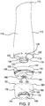
- Dispensing system 100 includes a container (e.g., a bottle 110), a valve cap 140, and a dosing cap 160. Together, valve cap 140 and dosing cap 160 may form a dispensing attachment for bottle 110.
- Valve cap 140 regulates the dispensing of a flowable product from bottle 110 into dosing cap 160.
- flowable product may be dispensed from bottle 110 into dosing cap 160 via valve cap 140 when dispensing system 100 is in an inverted position (i.e., when bottle 110 is in an inverted position), as shown in FIG. 1 .
- dispensing system 100 may dispense a flowable product into dosing cap 160 while dosing cap 160 is attached to valve cap 140.
- flowable product may be dispensed from bottle 110 when dosing cap 160 is attached to and locked on valve cap 140. While dispensing into dosing cap 160 is specifically discussed herein, flowable product can also be dispensed from valve cap 140 directly to a desired location (e.g., in a detergent reservoir in a laundry machine). Additionally, flowable product can be dispensed into dosing cap 160 when dosing cap 160 is detached from valve cap 140.
- Bottle 110 has a distal end 112, a proximal end 114, and a side wall 116 extending between distal end 112 and proximal end 114.
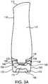
- Distal end 112, proximal end 114, and side wall 116 define an interior volume 117 (see e.g., FIG. 3A ) for holding a flowable product.
- Flowable product may be, for example, a fluid, a gel, a powder, or a granulated product.
- the flowable product may be, but is not limited to, a laundry care product (e.g., a detergent, a fabric softener, a fabric conditioner, a scent additive, a bleach, etc.), a dish detergent, an automotive fluid, a household or industrial cleaner, a degreaser, an industrial fluid, a pharmaceutical compound (e.g., a medicine), a personal care product (e.g., a mouthwash), or a food product (e.g., a condiment).
- a laundry care product e.g., a detergent, a fabric softener, a fabric conditioner, a scent additive, a bleach, etc.
- a dish detergent e.g., an automotive fluid, a household or industrial cleaner, a degreaser, an industrial fluid, a pharmaceutical compound (e.g., a medicine), a personal care product (e.g., a mouthwash), or a food product (e.g., a condiment).
- a pharmaceutical compound e.
- bottle 110 may include a gripping portion 128 to increase the ease in which a user can grasp and squeeze bottle 110.
- gripping portion 128 may include a concave curvature located between distal end 112 and proximal end 114 so as to improve grip and squeezability.
- gripping portion 128 may have a reduced circumference compared the rest of side wall 116.
- At least a portion of side wall 116 includes a portion that is sufficiently flexible (i.e., composed of a flexible material) to allow a user to squeeze bottle 110 and dispense a flowable product.
- entire side wall 116 may be composed of a flexible material.
- entire bottle 110 is composed of a flexible material. While the container of dispensing system 100 is discussed herein as a bottle, other squeezable containers for dispensing flowable product may be used including, but not limited to, pouches (e.g., stand-up pouches) or deformable tubes (e.g., similar to a toothpaste tube).
- side wall 116 should deform when a user squeezes bottle 110.
- side wall 116 has enough structural rigidly to support the weight of bottle 110 and a flowable product contained therein.
- side wall 116 may retain its shape unless a significant force is applied to bottle 110 (e.g., force imparted by a user squeezing bottle 110).
- the flexible material of side wall 116 may have enough structural rigidity such that merely grasping bottle 110 does not cause a deformation of side wall 116 and/or a decrease of internal volume 117.
- side wall 116 may not retain its shape and may not provide enough structural rigidly to support its own weight and a flowable product contained therein (e.g., if the container of dispensing system in a flexible pouch).
- side wall 116 When side wall 116 is squeezed with a sufficient amount of force, side wall 116 will deform. This deformation decreases the internal volume 117 of bottle 110 thereby forcing flowable product contained therein out of bottle 110.
- side wall 116, or a portion thereof should be flexible enough so as to allow a user to deform side wall 116 with relative ease.
- side wall 116, or a portion thereof is flexible enough to allow a user to increase the pressure within bottle 110 such that a valve on valve cap 140 can be actuated with relative ease.
- side wall 116 is flexible enough to allow a user to increase the pressure within bottle by at least 0.83 psi +/- 0.18 psi (23 in.H 2 O +/- 5 in.H 2 O) with relative ease.
- side wall 116 or a portion thereof, will at least partially return to its approximate original shape and/or volume after removal of the force imparted by a user squeezing bottle 110. In some embodiments, side wall 116, or a portion thereof, will fully return to its original shape and/or volume after removal of the force imparted by a user squeezing bottle 110.
- a bottle 110 that returns to its original shape, either partially or fully, may be aesthetically pleasing for a user. Moreover, it may increase a user's confidence in the robustness of bottle 110.
- Side wall 116 may be composed of one or more flexible materials including polymeric materials, such as, but not limited to, polypropylene (PP), polyethylene (PE), high-density polyethylene (HDPE), polyamides (PA) polyethylene terephthalate (PET), polyvinylchloride (PVC).
- side wall 116, or a portion thereof may be composed a flexible metallic material, such as aluminum. It should be appreciated that the thickness of side wall 116, or a portion of thereof, may dictate the flexibility of side wall 116.
- side wall 116 may be composed of a single material that is sufficiently flexible to allow a user to deform side wall 116 with relative ease.
- side wall 116 may be composed of a plurality of materials, where at least one of the materials is sufficiently flexible to allow a user to deform side wall 116 with relative ease.
- Distal end 112 and proximal end 114 of bottle 110 may be composed of the same material as side wall 116 or may be composed of different materials.
- Bottle 110 may be transparent, translucent, or opaque. In some embodiments, side wall 116 may be partially opaque and partially transparent and/or translucent. In such embodiments, the transparent and/or translucent portion of side wall 116 may provide a visual indicator showing the amount of flowable product remaining within bottle 110.
- Bottle 110 may have any shape or size configured to hold any amount of product. As a non-limiting example, bottle 110 may hold between approximately 50 mL and approximately 2000 mL of product. As another non-limiting example, bottle 110 may have a height in the range of 6 inches to 12 inches. The size, shape, and interior volume 117 of bottle 110 may depended on the type of flowable product contained within bottle.
- Distal end 112 of bottle 110 may be closed while proximal end 114 of bottle 110 may include an opening 122 that allows a flowable product to be dispensed from bottle 110.
- Proximal end 114 may include a neck 120 that forms opening 122.
- proximal end 114 may include a shoulder 118 connecting side wall 116 to neck 120.
- shoulder 118 may include an alignment feature 119 for engaging a corresponding alignment feature on valve cap 140.
- shoulder 118 may include a shoulder recess 126 for facilitating air flow between valve cap 140 and shoulder 118 (as described below in reference to FIG. 3B ). Shoulder recess 126 may also serve to relax manufacturing tolerances for bottle 110 and/or valve cap 140.
- valve cap 140 includes a distal end 142 and a proximal end 144.
- Valve cap 140 may include a valve cap body 146 and a valve cap skirt 148 disposed radially about valve cap body 146.
- Valve cap body 146 includes a dispending outlet 150 for dispensing a flowable product contained within bottle 110.
- a valve 152 in communication with dispensing outlet 150 may regulate the flow of product from bottle 110 through dispensing outlet 150.
- valve 152 When valve cap 140 is attached to bottle 110, valve 152 is in fluid communication with opening 122 of bottle 110 and resealably closes opening 122 of bottle 110.
- valve 152 may be in direct fluid communication with opening 122 of bottle 110.
- valve 152 may be directly attached to opening 122 of bottle 110 and valve cap 140 may be configured to receive and position valve 152 in communication with dispensing outlet 150.
- Valve 152 may allow a variable amount of flowable product to be dispensed from dispensing outlet 150.
- valve 152 may be a non-mechanical valve including a flexible material that opens and closes one or more resealable apertures formed in valve 152 when pressure is applied to/removed from bottle 110 (i.e., when bottle 110 is squeezed and released by a user).
- Valve 152 prevents dispensing of flowable product from opening 122 when bottle 110 in an inverted position and not being squeezed by a user (i.e., prevents the flowable product from leaking due to the effects of gravity).
- Valve 152 also prevents discharge of flowable product from dispensing outlet 150 due to an impact force imparted on flowable product when a user sets bottle 110 on a surface 102.
- valve 152 may be a slit valve including a polymeric membrane having one or more slits formed therein, such as, for example valve 560 or valve 600 described herein. The slits in the polymeric membrane may deform and open when pressure is applied to bottle 110 and close when the pressure is removed.
- the polymeric membrane of valve 152, and other parts of valve 152 may be composed of a polymeric material such as, but not limited to, natural rubber, synthetic rubber, silicone, silicone rubber, a thermoplastic elastomer, a thermoplastic vulcanizate, and combinations thereof.
- valve 152 may be a V21-200, a VI-220, or a VI-187 valve manufactured by Aptargroup, Inc.
- valve 152 may be secured to valve cap 140 using a retainer (e.g., a retainer ring) and retainer may be secured to valve cap 140 using, for example, a snap fit, an adhesive, a friction fit, or a heat weld.
- a retainer e.g., a retainer ring
- retainer may be secured to valve cap 140 using, for example, a snap fit, an adhesive, a friction fit, or a heat weld.
- Valve cap 140 attaches to proximal end 114 of bottle 110.
- valve cap skirt 148 may be sized and shaped to receive at least a portion of shoulder 118 when valve cap 140 is attached to bottle 110.
- valve cap 140 may liquid-tightly attach to neck 120.
- a connector 154 attached to valve cap body 146 may liquid-tightly attach to neck 120.
- Connector 154 may include an attachment mechanism 156 that liquid-tightly attaches to a corresponding attachment mechanism 124 on neck 120.
- an open end 155 of connector 154 may be sized and shaped (dimensioned) to receive at least a portion of neck 120.
- opening 122 in neck 120 may receive at least a portion of connector 154.
- Attachment mechanisms 124 and 156 may be any suitable releasable attachment mechanisms such as, but not limited to, threaded connectors, luer-lock connectors, friction fit connectors, snap-fit connectors, or a combination thereof.
- neck 120 and connector 154 may alternatively or additionally be permanently attached using, for example, an adhesive.
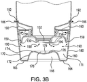
- Valve cap 140 may also include one or more venting apertures 158 formed in either valve cap body 146 and/or valve cap skirt 148. Venting apertures 158 allow air to flow into and out of dosing cap 160 when dosing cap 160 is attached to valve cap 140. When a flowable product is dispensed into dosing cap 160 attached to valve cap 140, venting apertures 158 allow air to flow out of dosing cap 160. This air flow increases the ease of filling dosing cap 160 with flowable product when bottle 110 is squeezed by alleviating pressure build up within dosing cap 160. Alleviating pressure build up also prevents dosing cap 160 from being forced off valve cap 140 during dispensing.
- venting apertures 158 allows air to flow into dosing cap 160 and into dispensing outlet 150 after flowable product is dispensed.
- This air flow into dosing cap 160 and dispensing outlet 150 prevents vacuum build up within bottle 110 and/or dosing cap 160, thereby allowing the bottle 110 to return, fully or at least partially, to its original shape after dispensing while dosing cap 160 is attached to valve cap 140.
- the air flow facilitated by venting apertures 158 is described in greater detail below with reference to FIG. 3B .
- Valve cap 140 may be or may include any of the features (as long as the features are not mutually exclusive) of valve caps 200, 300, 400, and 500 described herein.
- valve cap body 146 and valve cap skirt 148 may be a single integrally formed piece (e.g., using injection molding and/or machining).
- valve cap body 146 and valve cap skirt 148 may be separate pieces connected using, for example, a heat weld.
- Valve cap 140 may be composed of any suitable material including a polymeric material, such as, but not limited to, polypropylene (PP), polyethylene (PE), high density polyethylene (HDPE), polycarbonate (PC), polyamides (PA) polyethylene terephthalate (PET), polyvinylchloride (PVC), polystyrene (PS), and combinations thereof.
- a polymeric material such as, but not limited to, polypropylene (PP), polyethylene (PE), high density polyethylene (HDPE), polycarbonate (PC), polyamides (PA) polyethylene terephthalate (PET), polyvinylchloride (PVC), polystyrene (PS), and combinations thereof.
- Dosing cap 160 may attach to valve cap 140 and includes an open end 162 and a closed end 164. Open end 162 of dosing cap 160 may be sized and shaped to receive at least a portion of valve cap 140 when attached to valve cap 140. Dosing cap 160 also includes an outer circumferential wall 170 connected to a base wall 165 and extending between open end 162 and closed end 164. Open end 162, base wall 165, and outer circumferential wall 170 form a chamber 171 for receiving a flowable product dispensed from bottle 110.
- outer circumferential wall may define a coupling 184 that attaches to a coupling on a valve cap (e.g., coupling 260 on valve cap 200).
- coupling 184 may be configured to release from valve cap 140 before valve cap 140 detaches from bottle 110, preventing accidental removal of valve cap during use.
- Base wall 165 may be configured to support dispensing system 100 in an inverted position on surface 102 (see e.g., FIG. 1 ).
- Base wall 165 may have any shape capable of supporting dispensing system 100 in an inverted position.
- the size and shape of base wall 165 may be chosen based on the size and shape of bottle 110.
- a base wall 165 configured to support dispensing system 100 in an inverted position encourages storage in an inverted position, which may aid in efficiently dispensing flowable product from bottle 110 because flowable product will collect at proximal end 104 of bottle 110 due to gravity.
- dosing cap 160 may attach to bottle 110.
- Chamber 171 of dosing cap 160 may have any suitable volume. As a non-limiting example, chamber 171 may hold between about 10 mL and about 250 mL of a flowable product. The volume of chamber 171 may depend on the type of flowable product contained within bottle 110 and/or the typical recommended doses for a flowable product. After a flowable product is dispensed into dosing cap 160, it may be poured from dosing cap 160 via open end 162.
- the walls of dosing cap 160 may have continuous curvature (i.e., no corners) so as to minimize splashing of flowable product dispensed into dosing cap 160 and to prevent the accumulation of residue within dosing cap 160.
- dosing cap 160 may include dose indicators 168 for indicating specific volume amounts within dosing cap 160 (i.e., specific doses of flowable product).
- Dose indicators 168 may be, but are not limited, projections or depressions formed on outer circumferential wall 170 (e.g., molded with dosing cap 160) or colored lines formed on outer circumferential wall 170.
- dose indicators 168 may be formed on an outer surface 180 of outer circumferential wall 170 to reduce residue accumulation within the dosing cap 160.
- dose indicators 168 may be formed on an inner surface 182 of circumferential wall 170 and protrude into chamber 171 so as to create a smooth outer surface 180 that facilities the attachment of a label (e.g., label 720).
- Dose indicators 168 may be any size or shape.
- dose indicators 168 are large enough so as not to be obfuscated by product dispensed into dosing cap 160.
- Dosing cap 160 may be composed of any suitable material including a polymeric material such as, but not limited to, polypropylene (PP), polyethylene (PE), high density polyethylene (HDPE), polycarbonate (PC), polyamides (PA) polyethylene terephthalate (PET), polyvinylchloride (PVC), polystyrene (PS), and combinations thereof.
- the material of dosing cap 160 may be transparent, translucent, or opaque. A transparent or translucent dosing cap 160 allows a user to see the amount of flowable product held within chamber 171 of dosing cap 160.
- the material of dosing cap 160 may be any color.
- the color of dosing cap 160 may match the color of the flowable product contained within bottle 110.
- a color match between dosing cap 160 and the flowable material may reduce the visibility of any flowable product residue remaining within chamber 171 after the flowable product is poured from dosing cap 160. Such a color match may provide a more aesthetically pleasing dispensing system 100 that exudes cleanliness.
- the material of dosing cap 160 may be a hydrophobic material or may include an anti-stick agent or a hydrophobic additive to prevent the accumulation of residue within chamber 171.
- the interior surface of chamber 171 may be coated within a hydrophobic coating and/or have surface texturing to prevent the accumulation of residue.
- dosing cap 160 may include an inner circumferential wall 172 connected to base wall 165 and spaced apart from outer circumferential wall 170 within chamber 171.
- An elevated wall 174 located between base wall 165 and open end 162 of dosing cap 160 may be connected to inner circumferential wall 172.
- inner circumferential wall 172 and elevated wall 174 may define a cavity 166 located at closed end 164 of dosing cap 160. Cavity 166 serves to reduce the cross-sectional volume of dosing cap 160 adjacent to closed end 164. This allows for greater visual differentiation between graduated amounts of flowable product held within chamber 171 of dosing cap 160.
- dose indicators 168 a greater differentiation between graduated amounts of flowable product allows dose indicators 168 to be separated by a larger distance, thereby making it easier for a user to accurately measure out different dosages and/or volumes of flowable product.
- elevated wall 174 may include an elevated surface 176 having a concave shape. In other words, elevated wall 174 may include an elevated surface 176 that forms a depression 178. In such embodiments, depression 178 may extend into cavity 166. Depression 178 may be positioned below dispensing outlet 150 of valve cap 140 when dosing cap 160 is attached to valve cap 140. In some embodiments, an apex 179 of depression 178 (i.e., the portion of depression 178 that extends furthest into cavity 166) may be positioned directly below the flow path of a flowable product being dispensed from dispensing outlet 150 when dosing cap 160 is attached to valve cap 140. Depression 178 may facilitate an even flow of product around inner circumferential wall 172 when product is dispensed into dosing cap 160, thereby reducing splashing and residue build up.
- dosing cap 160 may be removably attached to valve cap 140.
- dosing cap 160 may be attached, detached, and re-attached to valve cap 140.
- Dosing cap 160 may be attached to valve cap 140 via any suitable removable attachment mechanism, such as, but not limited to, a threaded attachment, a snap-fit attachment, a luer-lock type attachment, a friction fit, or combinations thereof.
- a threaded attachment e.g., fully screwed onto valve cap 140 or fully snapped into place on valve cap 140
- dosing cap 160 is locked on valve cap 140.
- the air flow 190 created by venting aperture(s) 158 allows flowable product to be dispensed from bottle 110 when dosing cap is locked on valve cap 140.
- air flow 190 allows flowable product to be dispensed from bottle 110 when dosing cap 160 is locked on valve cap 140 and when bottle 110 is in an inverted position (see e.g., FIG. 1 ) with opening 122 disposed below distal end 112 of bottle 110.
- FIG. 3B air flows into and out of dosing cap 160 when dosing cap 160 is locked on valve cap 140.
- bottle 110 When bottle 110 is released by a user, air flows into dispensing system 100 via gap 192, through valve cap 140, and into dosing cap 160 via venting aperture(s) 158. After entering dosing cap 160, the air may flow into bottle 110 via dispensing outlet 150. The flow of air into dosing cap 160 and bottle 110 prevents vacuum build up within bottle 110 and/or dosing cap 160, thereby allowing the bottle 110 to return, fully or at least partially, to its original shape after dispensing.
- FIGS. 5 - 7 show a valve cap 200 according to an embodiment.
- Valve cap 200 includes a distal end 202 and a proximal end 204.
- Valve cap 200 may include a valve cap body 210 and a valve cap skirt 250.
- Valve cap body 210 may include a dispending outlet extending from an external surface 214 of valve cap body 210 towards proximal end 204 of valve cap 200.
- dispensing outlet 218 may be flush with external surface 214 or recessed below external surface 214 such that dispensing outlet 218 does not extend down into dosing cap 160 when dosing cap 160 is attached to valve cap 200.
- Dispensing outlet 218 includes a through hole 219 that allows a flowable product contained within bottle 110 to be dispensed via valve cap 200.
- valve cap body 210 and valve cap skirt 250 may be a single integrally formed piece (e.g., using injection molding and/or machining). In some embodiments, valve cap body 210 and valve cap skirt 250 may be separate pieces connected using, for example, a heat weld.
- Valve cap 200 may be composed of any suitable material including a polymeric material, such as, but not limited to, polypropylene (PP), polyethylene (PE), high density polyethylene (HDPE), polycarbonate (PC), polyamides (PA) polyethylene terephthalate (PET), polyvinylchloride (PVC), polystyrene (PS), and combinations thereof.
- PP polypropylene
- PE polyethylene
- HDPE high density polyethylene
- PC polycarbonate
- PA polyamides
- PET polyethylene terephthalate
- PVC polyvinylchloride
- PS polystyrene
- Dispensing outlet 218 may include a valve 232 positioned in or adjacent to through hole 219 to regulate the flow of product from bottle 110 through dispensing outlet 218.
- Valve 232 may be the same as or similar to valve 152 discussed above.
- dispensing outlet 218 may include a valve support 228 for securing valve 232 to valve cap 200.
- valve support 228 may be integrally formed within dispensing outlet 218.
- valve support 228 may be a separate piece, such as retainer 580, 620, or 720 described herein, that is fixed to dispensing outlet 218 (e.g., adjacent to or within through hole 219).
- valve support 228 may be fixed to dispensing outlet 218 via, for example, an adhesive, a friction fit, or a heat weld.
- valve cap 200 attaches to proximal end 114 of bottle 110.
- valve cap 200 may liquid-tightly attach to neck 120 via a connector 220.
- connector 220 may be connected to and extend from an internal surface 216 of valve cap body 210 towards distal end 202 of valve cap 200.
- connector 220 may be integrally formed with valve cap body 210 (e.g., by injection molding).
- Connector 220 may include an attachment mechanism 224 that liquid-tightly attaches to corresponding attachment mechanism 124 on neck 120.
- an open end 222 of connector 220 may be sized and shaped to receive at least a portion neck 120.
- opening 122 in neck 120 may receive at least a portion of connector 220.
- Attachment mechanism 224 may be any suitable releasable attachment mechanism such as, but not limited to, a threaded connector, a luer-lock connector, a friction fit connector, a snap-fit connector, or a combination thereof.
- neck 120 and connector 220 may alternatively or additionally be permanently attached using, for example, an adhesive.
- Valve cap skirt 250 may be disposed radially about connector 220.
- a rim 252 of valve cap skirt 250 may include a portion that extends above connector 220 towards open distal end 202 of valve cap 200 such that a distal rim end 254 of rim 252 is disposed above connector 220 when valve cap 200 is in an inverted position (see e.g., FIG. 5 ).
- Rim 252 may be sized and shaped to receive at least a portion of shoulder 118 on bottle 110.
- distal rim end 254 may form a gap, or at least a portion of a gap, between bottle 110 and valve cap 200 to allow for air flowing into and out of a dosing cap attached to valve cap 200 (see e.g., FIG. 3B ).
- rim 252 may include a ledge 256 for engaging a distal lip 186 of dosing cap 160.
- Ledge 256 may serve to properly position dosing cap 160 on valve cap 140.
- Ledge 256 may also serve as a stop wall that contacts distal lip 186 of dosing cap 160 when dosing cap 160 is fully attached to valve cap 200 (i.e., locked on valve cap 200). In some embodiments, when distal lip 186 of dosing cap 160 contacts ledge 256, dosing cap 160 is locked on valve cap 200.
- Valve cap skirt 250 may also define a coupling 260 for removably attaching to coupling 184 disposed on dosing cap 160.
- Coupling 260 may be formed on an outer surface 251 of valve cap skirt 250.
- Couplings 260 and 184 may be any suitable releasable attachment mechanisms such as but not limited to, threaded connectors, luer-lock connectors, friction fit connectors, snap-fit connectors, or a combination thereof.
- coupling 260 may include threads 261, one or more locking tabs 262, and one or more locking recesses 264.
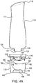
- Locking recesses 264 may be sized and shaped to receive a locking projection 185 of coupling 184 (see FIGS. 4A and 4B ).
- locking projection(s) 185 may lock dosing cap 160 onto valve cap 200 when received within locking recess(es) 264.
- dosing cap 160 is locked on valve cap 200.
- the placement of coupling 260 having threads 261, locking tab(s) 262 and locking recess(es) 264 on valve cap 200 rather than the dosing cap 160, and the use of locking projections 185 instead of threads on dosing cap 160 may help reduce the accumulation of residue on dosing cap 160. In such an embodiment, residue may not collect and become trapped between threads.
- locking projections 185 provide less surface area for the accumulation of residue, compared to one or more threads radially disposed on dosing cap 160.
- Valve cap 200 may also include one or more feet 270.
- valve cap body 210 and valve cap skirt 250 may define one or more feet 270.
- Feet 270 may extend from external surface 214 of valve cap body 210 towards proximal end 204. In other words, feet 270 extend below external surface 214 when valve cap 200 is in an inverted position (see e.g., FIG. 7 ).
- feet 270 extend from external surface 214 towards closed end 164 of dosing cap 160 (see e.g., feet 159 in FIGS. 3A and 3B ).
- Valve cap 200 may include any number of feet 270 disposed in any configuration.
- Feet 270 may be radially disposed about dispensing outlet 218. In some embodiments, feet 270 are evenly radially spaced about dispensing outlet 218.
- Feet 270 include proximal surfaces 274 disposed at the proximal end of feet 270.
- proximal surfaces 274 extend below the most proximal portion of dispensing outlet 218 and, as such, define the most proximal portion of valve cap 200.
- the height 280 of feet 270 may be greater than the height 282 of dispensing outlet 218 (both heights being measured from external surface 214 of valve cap 200).
- feet 270 serve to support bottle 110 in an inverted position on surface 102 when dosing cap 160 is not attached to valve cap 200.
- feet 270 may help signal to a user that bottle 110, with valve cap 200 attached, may be placed on surface 102 in an inverted position.
- Spaces 272 separate feet 270 and allow air flow between adjacent feet 270. Spaces 272 also prevent the formation of a vacuum seal forming between valve cap 200 and surface 102 in the event valve cap 200 is placed directly on surface 102, which may be wet or otherwise covered with residue.
- Valve cap 200 may also include one or more venting apertures 258 formed in either the valve cap body 210 and/or valve cap skirt 250. As discussed above with reference to venting apertures 158, venting apertures 258 allow for air flow into and out of dosing cap 160 when dosing cap 160 is locked on valve cap 200. Venting apertures 258 may be the same as or similar to venting apertures 158. In some embodiments, as shown in FIGS. 5 and 6 , venting apertures 258 may be formed in and/or adjacent to ledge 256 on valve cap skirt 250. In some embodiments, venting apertures 258 may be formed in and/or adjacent to ledge 256 at locations corresponding to the locations of locking recesses 264.
- dispensing system 100 may include a stop valve configured to allow dispensing of a flowable product (e.g., open an opening in a valve cap) when dispensing system 100 is in an inverted position and prevent dispensing of a flowable product (e.g., close an opening in a valve cap) when dispensing system 100 is in an upright position.
- the stop valve may be included on a valve cap. The stop valve may function relative to the position of bottle 110.
- the stop valve may be a reversibly actuated by turning dispensing system 100 upside-down (inverted portion) and right-side up (upright position).
- the stop valve may be actuated by, for example, gravity, pressure, buoyancy, or a combination thereof.
- the stop valve may include one or more movable parts that open an opening in a valve cap to allow dispensing of product and close an opening in the valve cap to prevent dispensing of product.
- FIGS. 8A - 10B show a valve cap 300 including a stop valve according to an embodiment.
- Valve cap 300 includes a distal end 302 and a proximal end 304. Similar to valve cap 200, valve cap 300 may include a valve cap body 310 and a valve cap skirt 350. Valve cap body 310 and valve cap skirt 350 may be the same as or similar to valve cap body 210 and valve cap skirt 250. Also, similar to valve cap 200, valve cap 300 attaches to proximal end 114 of bottle 110. In some embodiments, valve cap 300 may liquid-tightly attach to neck 120 via a connector 320. Connector 320 may be the same as or similar to connector 220.
- a dispensing outlet 318 of valve cap 300 may include a valve 332 positioned in or adjacent to a through hole 319 to regulate the flow of product from bottle 110 through dispensing outlet 318.
- dispensing outlet 318 may include a valve support 328 for securing valve 332 to valve cap 300.
- Valve support 328 may be the same as or similar to valve support 228.
- Valve 332 may be the same as or similar to valve 152 discussed above.
- Valve cap 300 also includes a valve assembly 360.
- Valve assembly 360 may include a valve body 364, and a stop valve 372.
- Valve body 364 is a hollow structure having a proximal opening 368 and one or more distal openings 366. In some embodiments, distal openings 366 may be formed in a side wall of valve body 364.
- Valve body 364 may be secured to a fitting 362 connected to valve cap body 310.
- fitting 362 may be integrally formed with valve cap body 310 (e.g., using injection molding and/or machining).
- fitting 362 may be a separate piece attached to valve cap body 310 using, for example, an adhesive, a heat weld, a snap fit, or a friction fit.
- Proximal opening 368 of valve body 364 may be sized and shaped to receive at least a portion of fitting 362.
- fitting 362 may be sized and shaped to receive at least a portion of valve body 364.
- Valve body 364 may be secured to fitting 362 using, for example, an adhesive, a heat weld, a snap fit, or a friction fit.
- proximal opening 368 and distal openings 366 are in fluid communication with valve 332.
- proximal opening 368 is disposed below distal openings 366.
- proximal opening 368 is disposed above distal openings 366.
- Stop valve 372 may be moveable within valve body 364 between an open position (see FIGS. 8A and 10A ) and a closed position (see FIGS. 8B and 10B ).
- the open position is the position of valve cap 300 when it is attached to bottle 110 and dispensing system 100 is in an inverted position (see e.g., FIG. 1 ).
- the closed position is the position of valve cap 300 when attached to bottle 110 and dispensing system 100 is in an upright position (i.e., FIG. 1 rotated 180°).
- stop valve 372 opens one or more distal openings 366 formed in valve body 364.
- stop valve 372 closes distal openings 366.
- stop valve 372 allows flowable product to be dispensed from bottle 110 via valve cap 300 (e.g., when bottle 110 is squeezed by a user).
- stop valve 372 prevents flowable product from being dispensed from bottle 110 via valve cap 300 even if bottle 110 is squeezed by a user.
- the operation of stop valve 372 may prevent unintentional discharge of flowable product when bottle 110 is in the upright position.
- stop valve 372 may include a plunger in the form of a hollow ring 374 having a hollow center 376.
- Hollow ring 374 may be slidably disposed within valve body 364 so as to slide between fitting 362 (in the open/inverted position) and a stop wall 370 of valve body 364 (in the closed/upright position) (compare FIGS. 10A and 10B ).
- hollow ring 374 blocks flowable product from entering valve body 364 via distal openings 366 when in the closed/upright potion, but allows product to enter and flow through valve body 364 via distal openings 366 in the open/inverted position.
- flowable product may flow through valve body 364 towards valve 332 to be dispensed (e.g., when bottle 110 is squeezed by a user).
- FIGS. 11A - 13B show a valve cap 400 including a stop valve according to an embodiment.
- Valve cap 400 includes a distal end 402 and a proximal end 404. Similar to valve cap 200, valve cap 400 may include a valve cap body 410 and a valve cap skirt 450. Valve cap body 410 and valve cap skirt 450 may be the same as or similar to valve cap body 210 and valve cap skirt 250. Also similar to valve cap 200, valve cap 400 attaches to proximal end 114 of bottle 110. In some embodiments, valve cap 400 may liquid-tightly attach to neck 120 via a connector 420. Connector 420 may be the same as or similar to connector 220.
- a dispensing outlet 418 of valve cap 400 may include a valve 432 positioned in or adjacent to a through hole 419 to regulate the flow of product from bottle 110 through dispensing outlet 418.
- dispensing outlet 418 may include a valve support 428 for securing valve 332 to valve cap 300.
- Valve support 428 may be the same as or similar to valve support 228.
- Valve 432 may be the same as or similar to valve 152 discussed above.
- Valve cap 400 also includes a valve assembly 460.
- Valve assembly 460 may include a valve body 464, and a stop valve 472. Similar to valve body 364, valve body 464 is a hollow structure having a proximal opening 468 and one or more distal openings 466. In some embodiments, distal openings 466 may be formed in a side wall of valve body 464.
- Valve body 464 may be secured to a fitting 462 connected to valve cap body 410.
- fitting 462 may be integrally formed with valve cap body 410 (e.g., using injection molding and/or machining).
- fitting 462 may be a separate piece attached to valve cap body 410 using, for example, an adhesive, a heat weld, a snap fit, or a friction fit.
- Proximal opening 468 of valve body 464 may be sized and shaped to receive at least a portion of fitting 462.
- fitting 462 may be sized and shaped to receive at least a portion of valve body 464.
- Valve body 464 may be secured to fitting 462 using, for example, an adhesive, a heat weld, a snap fit, or a friction fit.
- proximal opening 468 and distal openings 466 are in fluid communication with valve 432.
- proximal opening 468 is disposed below distal openings 466.
- proximal opening 468 is disposed above distal openings 466.
- Stop valve 472 may be moveable within valve body 464 between an open position (see FIGS. 11A and 13A ) and a closed position (see FIGS. 11B and 13B ).
- the open position is the position of valve cap 400 when it is attached to bottle 110 and dispensing system 100 is in an inverted position (see e.g., FIG. 1 ).
- the closed position is the position of valve cap 400 when attached to bottle 110 and dispensing system 100 is in an upright position (i.e., FIG. 1 rotated 180°).
- stop valve 472 opens one or more distal openings 466 formed in valve body 464.
- stop valve 472 closes distal openings 466.
- stop valve 472 allows flowable product to be dispensed from bottle 110 via valve cap 400 (e.g., when bottle 110 is squeezed by a user).
- stop valve 472 prevents flowable product from being dispensed from bottle 110 via valve cap 400 even if bottle 110 is squeezed by a user.
- the operation of stop valve 472 may prevent unintentional discharge of flowable product when bottle 110 is in the upright position.
- stop valve 472 may include a plunger having a plug 476 and retainer 480 connected to opposite ends of a shaft 474.
- Plug 476 may be slidably disposed within valve body 464 so as to slide between fitting 462 (in the open/inverted position) and a stop wall 470 of valve body 464 (in the closed/upright position) (compare FIGS. 13A and 13B ).
- Stop wall 470 may include an opening 471 sized and shaped to slidably receive shaft 474. The slidable interface between opening 471 and shaft 474 may guide plug 476 between the open position and the closed position.
- Retainer 480 may serve to prevent shaft 474 from sliding completely through opening 471 and may serve to properly position plug 476 within valve body 464 in the closed position.
- plug 476 may include one or more orifices 478 that allow flowable product to flow through plug 476 towards valve 432 when stop valve 472 is in the open/inverted position.
- plug 476 blocks flowable product from entering valve body 464 via distal openings 466 when in the closed/upright potion, but allows product to enter and flow through valve body 464 via distal openings 466 in the open/inverted position.
- flowable product may flow through valve body 464 towards valve 432 to be dispensed (e.g., when bottle 110 is squeezed by a user).
- FIGS. 14A and 14B show a valve cap 500 according to an embodiment.
- Valve cap 500 includes a distal end 502 and a proximal end 504. Similar to valve cap 200, valve cap 500 may include a valve cap body 510 and a valve cap skirt 550. Valve cap body 510 and valve cap skirt 550 may be the same as or similar to valve cap body 210 and valve cap skirt 250. Also similar to valve cap 200, valve cap 500 attaches to proximal end 114 of bottle 110. In some embodiments, valve cap 500 may liquid-tightly attach to neck 120 via a connector 520. Connector 520 may be the same as or similar to connector 220.
- a dispensing outlet 518 of valve cap 500 may include a valve 560 positioned in or adjacent to a through hole 519 to control the flow of product from bottle 110 through dispensing outlet 518.
- Valve 560 may be secured within or adjacent to through hole 519 using a retainer 580.
- through hole 519 may be an elongated through hole.
- FIG. 15 shows valve 560 and retainer 580 according to an embodiment.
- Valve 560 may include an outer wall 564 and an inner wall 566 attached to outer wall 564.
- Inner wall 566 may be attached to a polymeric membrane 562 that is in direct fluid communication with opening 122 of bottle 110 when valve cap 500 is attached to bottle 110.
- Inner wall 566 is configured to invert (i.e., unfold) when valve 560 is actuated (e.g., when a user squeezes bottle 110).
- Retainer 580 may include a hollow body 582 having an open proximal end 585 and an open distal end 583. And hollow body 582 may define a coupling 584 and a valve seat 586. Valve seat 586 may be sized and shaped to receive at least a portion valve 560. When assembled, at least a portion of valve 560 is received within valve seat 586 and a distal rim 561 of outer wall 564 may be seated on a ledge 588 of valve seat 586.
- Coupling 584 may secure retainer 580 within or adjacent to through hole 519. And coupling 584 may be secured within or adjacent to through hole 519 using, for example, an adhesive, welding, a snap fit, or a friction fit.
- retainer 580 may have a height 587, measured from open proximal end 585 to open distal end 583, that is less than or equal to the overall height, measured from a proximal rim 563 of outer wall 564 to the top of polymeric membrane 562, of valve 560.
- a retainer 580 having a height 587 that is less than or equal the overall height of valve 560 is deemed to be a "low profile" retainer.
- Such low profile embodiments may reduce the accumulation of residue between valve 560 and retainer 580 (e.g., by reducing the volume of space 730 as discussed below in reference to FIG. 17A ).
- the height 587 is less than the overall height of valve 560.
- height 587 of retainer 580 is such that at least a portion of valve 560 (e.g., at least a portion of polymeric membrane 562) extends from open distal end 583 when valve 560 and retainer 580 are assembled (see, e.g., FIGS. 17A and 17B ).
- retainer 580 may have a ring shape.
- polymeric membrane 562 is forced up and down when bottle 110 is squeezed by a user.
- polymeric membrane 562 is forced downward (i.e., towards open proximal end 585 of retainer 580)
- one or more slits 568 formed in inner wall 566 open due to polymeric membrane 562 pulling inner wall 566 downwards.
- the downward force of polymeric membrane 562 opens slits 568 and allows flowable product to be dispensed from bottle 110 through dispensing outlet 518, via open slits 568.
- polymeric membrane 562 moves upward towards open distal end 583 of retainer 580, inner wall 566 folds back towards distal rim 561 of outer wall 564, and slits 568 close, thereby sealing opening 122 of bottle 110.
- valve 560 and the location of slits 568 on inner wall 566 allows flowable product to be dispensed, but may also help prevent unintentional discharge of flowable product. Due to their location, slits 568 open in a direction perpendicular to a center dispensing axis 590 of through hole 519. And, when valve cap 500 is in an inverted position (see FIG. 14A ), flowable product located at opening 122 of bottle (due to gravity) can be squeezed through slits 568, into through hole 519, and out of dispensing outlet 518. But, when valve cap 500 is in an upright position (see FIG.
- any residue located in or around opening 122, connector, and/or retainer 580 is directed towards a sidewall 592 of through hole 519. As such, the residue is deflected off side wall 592 of through hole 519 rather than being discharged straight through through hole 519 in the direction of center dispensing axis 590.
- FIG. 16 shows a valve 600 and a retainer 620 according to an embodiment.
- Valve 600 may include an outer wall 604 and an inner wall 606 attached to outer wall 604.
- Inner wall 606 may be attached to a polymeric membrane 602 that is in direct fluid communication with opening 122 of bottle 110 when a valve cap (e.g., valve cap 140) is attached to bottle 110.
- a valve cap e.g., valve cap 140
- inner wall 606 is configured to invert (i.e., unfold) when valve 600 is actuated (e.g., when a user squeezes bottle 110).
- Retainer 620 may include a hollow body 622 having an open proximal end 625 and an open distal end 623. Hollow body 622 of retainer 620 may define a coupling 624 and a valve seat 626. Valve seat 626 may be sized and shaped to receive at least a portion of valve 600. When assembled, at least a portion of valve 600 is received within valve seat 626 and a distal rim 601 of outer wall 604 may be seated on a ledge 628 of valve seat 626. Coupling 624 may secure retainer 620 within or adjacent to a through hole of a dispensing outlet (e.g., through hole 219 of dispensing outlet 218).
- a dispensing outlet e.g., through hole 219 of dispensing outlet 218
- retainer 620 may be a low profile retainer having a height 627, measured from open distal end 623 to open proximal end 625, that is less than or equal to the overall height, measured from a proximal rim 603 of outer wall 604 to the top of polymeric membrane 602, of valve 600. In some embodiments, height 627 is less than the overall height of valve 600.
- the height 627 of retainer 620 is such that at least a portion of valve 600 (e.g., at least a portion of polymeric membrane 602) extends from open distal end 623 when valve 600 and retainer 620 are assembled (see, e.g., FIGS. 17A and 17B ).
- retainer 620 may have a ring shape.
- polymeric membrane 602 is forced up and down when bottle 110 is squeezed by a user.
- polymeric membrane 602 is forced downward (i.e., towards open proximal end 625 of retainer 620)
- one or more flexible flaps 610 defined by one or more slits 608 formed in polymeric membrane 602 open due to the downward force on polymeric membrane 602.
- Flaps 610 open as inner wall 606 unfolds towards proximal rim 603 of outer wall 604 and allow flowable product to be dispensed from bottle 110.
- inner wall 606 folds back towards distal rim 601 of outer wall 604, polymeric membrane 602 moves upward towards open distal end 623 of retainer 620, and flaps 610 close, thereby sealing opening 122 of bottle 110.
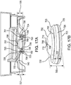
- FIGS. 17A and 17B show a valve 700 and a retainer 720 according to an embodiment.
- FIG. 17A shows valve 700 secured to a valve cap (e.g., valve cap 140) using valve retainer 720.
- Valve 700 may include an outer wall 704 and an inner wall 706 attached to outer wall 704.
- Inner wall 706 may be attached to a polymeric membrane 702 that is in direct fluid communication with opening 122 of bottle 110 when valve cap 140 is attached to bottle 110. Similar to inner walls 566 and 606, inner wall 706 is configured to invert (i.e., unfold) when valve 700 is actuated (e.g., when a user squeezes bottle 110).
- polymeric membrane 702 may have a hemispherical shape with at least a portion of the hemispherical shape extending from an open distal end 723 of valve retainer 720.
- Retainer 720 may include a hollow body 722 having an open proximal end 725 and open distal end 723. Hollow body 722 of retainer 720 may define a coupling 724 and a valve seat 726. Valve seat 726 may be sized and shaped to receive at least a portion of valve 700. When assembled, at least a portion of valve 700 is received within valve seat 726 and a distal rim 701 of outer wall 704 may be seated on a ledge 728 of valve seat 726. Coupling 724 may secure retainer 720 within or adjacent to a through hole of a dispensing outlet (e.g., dispensing outlet 150). And coupling 724 may be secured within or adjacent to the through hole using, for example, an adhesive, welding, a snap fit, or a friction fit. In some embodiments, retainer 720 may have a ring shape.
- retainer 720 is a low profile retainer having a height 727, measured from open proximal end 725 to open distal end 725, that is less than the overall height 705, measured from a proximal rim 703 of outer wall 704 to the top of polymeric membrane 702, of valve 700.
- the overall height 705 of valve 700 may be such that at least a portion of polymeric membrane 702 extends from open distal end 723 of retainer 720.
- the overall height 705 of valve 700 is greater than a distance measured from proximal rim 703 to open distal end 723 of retainer 720 when valve 700 and retainer 720 are assembled.
- polymeric membrane 702 is forced up and down when bottle 110 is squeezed by a user.
- polymeric membrane 702 is forced downward (i.e., towards open proximal end 725 of retainer 720)
- one or more flexible flaps 710 defined by one or more slits 708 formed in polymeric membrane 702 open due to the downward force on polymeric membrane 702.
- Flaps 710 open as inner wall 706 unfolds towards proximal rim 703 of outer wall 704 and allow flowable product to be dispensed from bottle 110.
- inner wall 706 folds back towards distal rim 701 of outer wall 704, polymeric membrane 702 moves upward towards and through open distal end 723 of retainer 720, and flaps 710 close, thereby sealing opening 122 of bottle 110.
- a low profile retainer reduces the volume of void space 730 present between a valve (e.g., valve 700) and the retainer when the two are assembled. Residue trapped within void space 730 may be inadvertently discharged when valve 700 is actuated while bottle 110 is in an upright position. A reduction in void space 730 reduces the volume of residue that may accumulate between valve 700 and retainer 720. This in turn reduces the amount of residue that may be inadvertently discharged from bottle 110 when bottle 110 is an upright position (see comparison of different valve/valve retainer assemblies in Table 1 below).
- a retainer having a larger height would not only increase the volume of void space 730, but may also allow residue to remain collected near polymeric membrane 702 even when bottle 110 is in an upright position (e.g., due to capillary forces holding residue within the portion of the retainer that extends above the top of polymeric membrane 702).
- the V21-200 (Standard) valve/valve retainer assembly includes a V21-200 valve and a standard retainer having a height greater than the overall height of the V21-200 valve.
- the V21-200 (Low Profile) valve/valve retainer assembly includes a V21-200 valve and a low profile retainer.
- the VI-187 (Standard) valve/valve retainer assembly includes a VI-187 valve and a standard retainer having a height greater than the overall height of the V1-187 valve.
- the V1-187 (Low Profile 1) valve assembly includes a V1-187 valve and a low profile retainer.
- the V1-187 (Low Profile 2) valve assembly includes a V1-187 valve and a retainer having a height less than the overall height of the V1-187 valve as shown in FIGS. 17A and 17B .
- a bottle having a valve cap with the respective valve and retainer attached thereto was inverted to allow flowable product to collect in the open proximal end. The bottle was then turned upright and the residue collected within the open proximal end was discharged by squeezing the bottle. The discharged residue was collected on a cloth and weighed. Table 1: Residue (in grams) collected in various valve/valve retainer assemblies Test No.
- the low profile retainers significantly reduced the amount of residue collected and discharged when compared to their standard counterparts.
- the low profile V21-200 retainer resulted in approximately 58% less residue collected.
- the low profile 1 VI-187 retainer resulted in approximately 66% less residue collected.
- the low profile 2 VI-187 retainer shown in FIGS. 17A and 17B resulted in approximately 63% less residue collected compared to the standard VI-187 retainer.
- FIG. 18 shows an exploded view of a dispensing system according to an embodiment.
- the dispensing system may include one or more removable seals, such as an induction seal 800 and an external seal 810.
- the dispensing system may include both induction seal 800 and external seal 810.
- Induction seal 800 may liquid-tightly seal opening 122 of bottle 110.
- External seal 810 may seal a dispensing outlet of a valve cap (e.g., dispensing outlet 150 of valve cap 140).
- induction seal 800 or external seal 810 may include a portion containing a fragrance (e.g., a fragrant coating or a permeable material that is soaked with a fragrance) so as to allow for a user to ascertain the fragrance of the liquid within the bottle without having to break the seal.
- external seal 810 may liquid-tightly seal dispensing outlet 150.
- external or induction seal 810/800 may allow air to pass so that a user can smell the contents of bottle 110.
- the dispensing system may include a label 820.
- Label 820 may be attached to external surface 180 of dosing cap 160.
- Label 820 may provide information related to at least one of the following: the type of flowable product contained within bottle 110, brand logos, and instructions for use of the dispensing system 100.
- label 820 may include a scratch-and-sniff portion that imitates the smell of the flowable product contained within bottle 110 when scratched.
Landscapes
- Engineering & Computer Science (AREA)
- Mechanical Engineering (AREA)
- Physics & Mathematics (AREA)
- Fluid Mechanics (AREA)
- General Physics & Mathematics (AREA)
- Ceramic Engineering (AREA)
- Closures For Containers (AREA)
Description
- The invention generally relates to a dispensing system for dispensing a flowable product from a bottle into a cap in an inverted position.
- Various designs of bottles and other packages are utilized to hold and dispense fluids for various uses. A variety of such bottles and packages currently exist, and are differentiated both in shape, orientation, and types of closure systems. These bottles may be sealed with screw top lids or flip top mechanisms. And some bottles may be designed to be stored in an inverted position. Additionally, some bottles include a cap that is attached to the top of the bottle. The cap may be used for measuring fluid poured from the bottle.
US 5 549 224 A , which accords with the preamble of claim 1, discloses a liquid medicine container having a dose measuring cap mounted thereon. - It is often time desirable to regulate the amount of a product (e.g., a fluid) utilized for a specific use and/or situation. In some instances, a measuring cap may be used to measure out a recommended dose of fluid. For example, it may be desirable to use a particular dose of a laundry care product for a particular load of laundry (e.g., a particular does of a detergent, a fabric softener, a fabric conditioner, a scent additive, a bleach, etc. may be recommended for different amounts and/or types of laundry (e.g., color, fabric). Other fluids, such as, but not limited to, dish detergents, automotive fluids, pharmaceutical products (e.g., a medicine), household and industrial cleaners, degreasers, industrial fluids, and personal care products may have recommended dosages for specific uses and/or situations. In addition to measuring specific doses, it may be desirable for a consumer to have a compact and self-contained dispensing system that allows for dispensing variable amounts of a fluid into a measuring/dosing cap. Additionally, it may be desirable for the dispensing system to be stored in an inverted position such that remaining fluid is always positioned for dispensing. Moreover, it may also be desirable for the dispensing system to dispense a fluid into the measuring cap without the need to disassemble the measuring cap from the dispensing system (i.e., dispense into a measuring cap while the measuring cap remains attached to the dispensing system).
- Embodiments of the present invention described herein, or elements thereof, may accomplish one or more of these and other objectives.
- The invention is defined by a dispensing system, comprising:a bottle including a proximal end and a distal end separated by a side wall which has a portion that is flexible, the proximal end including an opening;a valve cap liquid-tightly attached to the opening of the bottle, the valve cap including a valve in fluid communication with the opening of the bottle; and a dosing cap attached to the valve cap, including a closed end and an open end; wherein the valve cap allows a flowable product to be dispensed from the bottle into the dosing cap when the dosing cap is locked on the valve cap and the bottle is in an inverted position with the opening disposed below the distal end, wherein the valve cap further includes a venting aperture to allow air flow into and out of the dosing cap, characterized in that the venting aperture allows air to flow into and out of a gap located between the side wall of the bottle and the valve cap. Preferred embodiments of the invention are only defined by appended dependent claims 2-9.
-
-
FIG. 1 shows a dispensing system according to an embodiment. -
FIG. 2 shows an exploded perspective of a dispensing system according to an embodiment. -
FIG. 3A shows a cross-sectional view of the dispensing system inFIG. 1 .FIG. 3B shows an enlarged view of a portion ofFIG. 3A . -
FIG. 4A shows a cross-sectional view of the dispensing system inFIG. 2 .FIG. 4B shows an enlarged view of a portion ofFIG. 4A . -
FIG. 5 shows a top perspective view of a valve cap according to an embodiment. -
FIG. 6 shows a bottom perspective view of a valve cap according to an embodiment. -
FIG. 7 shows a cross-sectional view of a valve cap according to some embodiments, along the line 7-7' inFIG. 5 . -
FIGS. 8A and 8B show perspective views of a valve cap according to an embodiment in a first position and a second position, respectively. -
FIG. 9 shows an exploded perspective view of a valve cap according to an embodiment. -
FIGS. 10A and 10B show cross-sectional views of a valve cap according to an embodiment in a first position and a second position, respectively. -
FIGS. 11A and 11B show perspective views of a valve cap according to an embodiment in a first position and a second position, respectively. -
FIG. 12 shows an exploded perspective view of a valve cap according to an embodiment. -
FIGS. 13A and 13B show cross-sectional views of a valve cap according to an embodiment in a first position and a second position, respectively. -
FIGS. 14A and 14B show cross-sectional views of a valve cap according to an embodiment in a first position and a second position, respectively. -
FIG. 15 shows an exploded perspective view of a valve and retainer according to an embodiment. -
FIG. 16 shows an exploded perspective view of a valve and retainer according to an embodiment. -
FIGS. 17A and 17B show a valve and retainer according to an embodiment. -
FIG. 18 shows an exploded perspective view of a dispensing system according to an embodiment. - The present invention will now be described in detail with reference to embodiments thereof as illustrated in the accompanying drawings, in which like reference numerals are used to indicate identical or functionally similar elements. References to "one embodiment", "an embodiment", "an example embodiment", etc., indicate that the embodiment described may include a particular feature, structure, or characteristic, but every embodiment may not necessarily include the particular feature, structure, or characteristic. Moreover, such phrases are not necessarily referring to the same embodiment. Further, when a particular feature, structure, or characteristic is described in connection with an embodiment, it is within the knowledge of one skilled in the art to affect such feature, structure, or characteristic in connection with other embodiments whether or not explicitly described.
- The following examples are illustrative, but not limiting, of the present invention which is defined by appended claim 1. Preferred embodiments of the invention are only defined by dependent claims 2-9.
- The use of a recommended amount of product (e.g., fluid) is often times desirable for a specific need and/or situation. For example, a specific dose of a laundry care product (e.g., a detergent, a fabric softener, a fabric conditioner, a scent additive, a bleach, etc.) may be recommended for a specific load of laundry (e.g., specific amounts, colors, and/or fabrics in the load). Exceeding the recommended dosage may be unnecessary in some instances and wasteful. Moreover, in some instances, exceeding the recommended dosage can be harmful. For example, an excess amount of bleach may undesirably remove color from an article of clothing. As such, encouraging the use of a recommended dosage is of interest.
- A compact and aesthetically pleasing dispensing system that allows for dispensing variable amounts of a product into a measuring/dosing cap may encourage the use of a recommended dosage. Moreover, a dispensing system that is capable of dispensing a product into the measuring cap without the need to disassemble the measuring cap from the dispensing system before dispensing (i.e., dispensing into a measuring cap while the measuring cap remains attached to the dispensing system) may encourage the use of a recommended dosage. Also, removing the need to disassemble the measuring cap may reduce the chance of spilling product when measuring out a recommended dose.
- It may also be desirable for a dispensing system to dispense a constant stream of product (i.e. dispense product in a stream having constant volume and/or rate). A constant and repeatable stream may provide for a consistent dispensing experience for a user. Constant and repeatable dispensing facilitates freedom to use a measuring/dosing cap or to dispense directly into a desired area (e.g., in a detergent reservoir in a laundry machine) with predictability and reliability of the amount dispensed, which may also facilitate the use of a recommended dosage.
- Additionally, it may be desirable for the dispensing system to be stored in an inverted position such that flowable product remaining within dispensing system is always positioned for dispensing. A dispensing system that can effectively stored in an inverted position should prevent leakage of product and prevent unintentional discharge of product when rotated to an upright position.
-
FIGS. 1 - 4B show adispensing system 100 according to an embodiment of the present invention.Dispensing system 100 includes a container (e.g., a bottle 110), avalve cap 140, and adosing cap 160. Together,valve cap 140 anddosing cap 160 may form a dispensing attachment forbottle 110.Valve cap 140 regulates the dispensing of a flowable product frombottle 110 intodosing cap 160. In particular, flowable product may be dispensed frombottle 110 intodosing cap 160 viavalve cap 140 when dispensingsystem 100 is in an inverted position (i.e., whenbottle 110 is in an inverted position), as shown inFIG. 1 . Additionally, dispensingsystem 100 may dispense a flowable product intodosing cap 160 whiledosing cap 160 is attached tovalve cap 140. In some embodiments, flowable product may be dispensed frombottle 110 whendosing cap 160 is attached to and locked onvalve cap 140. While dispensing intodosing cap 160 is specifically discussed herein, flowable product can also be dispensed fromvalve cap 140 directly to a desired location (e.g., in a detergent reservoir in a laundry machine). Additionally, flowable product can be dispensed intodosing cap 160 whendosing cap 160 is detached fromvalve cap 140. -
Bottle 110 has adistal end 112, aproximal end 114, and aside wall 116 extending betweendistal end 112 andproximal end 114.Distal end 112,proximal end 114, andside wall 116 define an interior volume 117 (see e.g.,FIG. 3A ) for holding a flowable product. Flowable product may be, for example, a fluid, a gel, a powder, or a granulated product. In particular, the flowable product may be, but is not limited to, a laundry care product (e.g., a detergent, a fabric softener, a fabric conditioner, a scent additive, a bleach, etc.), a dish detergent, an automotive fluid, a household or industrial cleaner, a degreaser, an industrial fluid, a pharmaceutical compound (e.g., a medicine), a personal care product (e.g., a mouthwash), or a food product (e.g., a condiment). - In some embodiments,
bottle 110 may include agripping portion 128 to increase the ease in which a user can grasp andsqueeze bottle 110. In some embodiments, grippingportion 128 may include a concave curvature located betweendistal end 112 andproximal end 114 so as to improve grip and squeezability. In some embodiments, grippingportion 128 may have a reduced circumference compared the rest ofside wall 116. - At least a portion of
side wall 116 includes a portion that is sufficiently flexible (i.e., composed of a flexible material) to allow a user to squeezebottle 110 and dispense a flowable product. In some embodiments,entire side wall 116 may be composed of a flexible material. In some embodiments,entire bottle 110 is composed of a flexible material. While the container of dispensingsystem 100 is discussed herein as a bottle, other squeezable containers for dispensing flowable product may be used including, but not limited to, pouches (e.g., stand-up pouches) or deformable tubes (e.g., similar to a toothpaste tube). - The flexible material of
side wall 116, or a portion thereof, should deform when a user squeezesbottle 110. In some embodiments,side wall 116 has enough structural rigidly to support the weight ofbottle 110 and a flowable product contained therein. Moreover, in some embodiments,side wall 116 may retain its shape unless a significant force is applied to bottle 110 (e.g., force imparted by a user squeezing bottle 110). In other words, the flexible material ofside wall 116 may have enough structural rigidity such that merely graspingbottle 110 does not cause a deformation ofside wall 116 and/or a decrease ofinternal volume 117. In some embodiments,side wall 116 may not retain its shape and may not provide enough structural rigidly to support its own weight and a flowable product contained therein (e.g., if the container of dispensing system in a flexible pouch). - When
side wall 116 is squeezed with a sufficient amount of force,side wall 116 will deform. This deformation decreases theinternal volume 117 ofbottle 110 thereby forcing flowable product contained therein out ofbottle 110. Preferably,side wall 116, or a portion thereof, should be flexible enough so as to allow a user to deformside wall 116 with relative ease. In some embodiments,side wall 116, or a portion thereof, is flexible enough to allow a user to increase the pressure withinbottle 110 such that a valve onvalve cap 140 can be actuated with relative ease. In some embodiments,side wall 116, or a portion thereof, is flexible enough to allow a user to increase the pressure within bottle by at least 0.83 psi +/- 0.18 psi (23 in.H2O +/- 5 in.H2O) with relative ease. - In some embodiments,
side wall 116, or a portion thereof, will at least partially return to its approximate original shape and/or volume after removal of the force imparted by auser squeezing bottle 110. In some embodiments,side wall 116, or a portion thereof, will fully return to its original shape and/or volume after removal of the force imparted by auser squeezing bottle 110. Abottle 110 that returns to its original shape, either partially or fully, may be aesthetically pleasing for a user. Moreover, it may increase a user's confidence in the robustness ofbottle 110. -
Side wall 116, or a portion thereof, may be composed of one or more flexible materials including polymeric materials, such as, but not limited to, polypropylene (PP), polyethylene (PE), high-density polyethylene (HDPE), polyamides (PA) polyethylene terephthalate (PET), polyvinylchloride (PVC). In some embodiments,side wall 116, or a portion thereof, may be composed a flexible metallic material, such as aluminum. It should be appreciated that the thickness ofside wall 116, or a portion of thereof, may dictate the flexibility ofside wall 116. In some embodiments,side wall 116 may be composed of a single material that is sufficiently flexible to allow a user to deformside wall 116 with relative ease. In some embodiments,side wall 116 may be composed of a plurality of materials, where at least one of the materials is sufficiently flexible to allow a user to deformside wall 116 with relative ease.Distal end 112 andproximal end 114 ofbottle 110 may be composed of the same material asside wall 116 or may be composed of different materials. -
Side wall 116 andbottle 110 may be transparent, translucent, or opaque. In some embodiments,side wall 116 may be partially opaque and partially transparent and/or translucent. In such embodiments, the transparent and/or translucent portion ofside wall 116 may provide a visual indicator showing the amount of flowable product remaining withinbottle 110.Bottle 110 may have any shape or size configured to hold any amount of product. As a non-limiting example,bottle 110 may hold between approximately 50 mL and approximately 2000 mL of product. As another non-limiting example,bottle 110 may have a height in the range of 6 inches to 12 inches. The size, shape, andinterior volume 117 ofbottle 110 may depended on the type of flowable product contained within bottle. -
Distal end 112 ofbottle 110 may be closed whileproximal end 114 ofbottle 110 may include anopening 122 that allows a flowable product to be dispensed frombottle 110.Proximal end 114 may include aneck 120 that forms opening 122. In some embodiments,proximal end 114 may include ashoulder 118 connectingside wall 116 toneck 120. In some embodiments,shoulder 118 may include analignment feature 119 for engaging a corresponding alignment feature onvalve cap 140. In some embodiments,shoulder 118 may include ashoulder recess 126 for facilitating air flow betweenvalve cap 140 and shoulder 118 (as described below in reference toFIG. 3B ).Shoulder recess 126 may also serve to relax manufacturing tolerances forbottle 110 and/orvalve cap 140. - As shown, for example in
FIG. 2 ,valve cap 140 includes adistal end 142 and aproximal end 144.Valve cap 140 may include avalve cap body 146 and avalve cap skirt 148 disposed radially aboutvalve cap body 146.Valve cap body 146 includes adispending outlet 150 for dispensing a flowable product contained withinbottle 110. Avalve 152 in communication with dispensingoutlet 150 may regulate the flow of product frombottle 110 through dispensingoutlet 150. Whenvalve cap 140 is attached to bottle 110,valve 152 is in fluid communication withopening 122 ofbottle 110 and resealably closes opening 122 ofbottle 110. In some embodiments,valve 152 may be in direct fluid communication withopening 122 ofbottle 110. In some embodiments,valve 152 may be directly attached to opening 122 ofbottle 110 andvalve cap 140 may be configured to receive andposition valve 152 in communication with dispensingoutlet 150. -
Valve 152 may allow a variable amount of flowable product to be dispensed from dispensingoutlet 150. In some embodiments,valve 152 may be a non-mechanical valve including a flexible material that opens and closes one or more resealable apertures formed invalve 152 when pressure is applied to/removed from bottle 110 (i.e., whenbottle 110 is squeezed and released by a user).Valve 152 prevents dispensing of flowable product from opening 122 whenbottle 110 in an inverted position and not being squeezed by a user (i.e., prevents the flowable product from leaking due to the effects of gravity).Valve 152 also prevents discharge of flowable product from dispensingoutlet 150 due to an impact force imparted on flowable product when a user setsbottle 110 on asurface 102. In some embodiments,valve 152 may be a slit valve including a polymeric membrane having one or more slits formed therein, such as, forexample valve 560 orvalve 600 described herein. The slits in the polymeric membrane may deform and open when pressure is applied to bottle 110 and close when the pressure is removed. The polymeric membrane ofvalve 152, and other parts ofvalve 152, may be composed of a polymeric material such as, but not limited to, natural rubber, synthetic rubber, silicone, silicone rubber, a thermoplastic elastomer, a thermoplastic vulcanizate, and combinations thereof. In some embodiments,valve 152 may be a V21-200, a VI-220, or a VI-187 valve manufactured by Aptargroup, Inc. In some embodiments,valve 152 may be secured tovalve cap 140 using a retainer (e.g., a retainer ring) and retainer may be secured tovalve cap 140 using, for example, a snap fit, an adhesive, a friction fit, or a heat weld. -
Valve cap 140 attaches toproximal end 114 ofbottle 110. In some embodiments,valve cap skirt 148 may be sized and shaped to receive at least a portion ofshoulder 118 whenvalve cap 140 is attached to bottle 110. In some embodiments,valve cap 140 may liquid-tightly attach toneck 120. In some embodiments, aconnector 154 attached tovalve cap body 146 may liquid-tightly attach toneck 120.Connector 154 may include anattachment mechanism 156 that liquid-tightly attaches to acorresponding attachment mechanism 124 onneck 120. In some embodiments, anopen end 155 ofconnector 154 may be sized and shaped (dimensioned) to receive at least a portion ofneck 120. Alternatively, opening 122 inneck 120 may receive at least a portion ofconnector 154.Attachment mechanisms neck 120 andconnector 154 may alternatively or additionally be permanently attached using, for example, an adhesive. -
Valve cap 140 may also include one ormore venting apertures 158 formed in eithervalve cap body 146 and/orvalve cap skirt 148. Ventingapertures 158 allow air to flow into and out ofdosing cap 160 whendosing cap 160 is attached tovalve cap 140. When a flowable product is dispensed intodosing cap 160 attached tovalve cap 140, ventingapertures 158 allow air to flow out ofdosing cap 160. This air flow increases the ease of fillingdosing cap 160 with flowable product whenbottle 110 is squeezed by alleviating pressure build up withindosing cap 160. Alleviating pressure build up also preventsdosing cap 160 from being forced offvalve cap 140 during dispensing. Additionally, the flow of air though ventingapertures 158 allows air to flow intodosing cap 160 and into dispensingoutlet 150 after flowable product is dispensed. This air flow intodosing cap 160 and dispensingoutlet 150 prevents vacuum build up withinbottle 110 and/ordosing cap 160, thereby allowing thebottle 110 to return, fully or at least partially, to its original shape after dispensing whiledosing cap 160 is attached tovalve cap 140. The air flow facilitated by ventingapertures 158 is described in greater detail below with reference toFIG. 3B . -
Valve cap 140 may be or may include any of the features (as long as the features are not mutually exclusive) of valve caps 200, 300, 400, and 500 described herein. In some embodiments,valve cap body 146 andvalve cap skirt 148 may be a single integrally formed piece (e.g., using injection molding and/or machining). In some embodiments,valve cap body 146 andvalve cap skirt 148 may be separate pieces connected using, for example, a heat weld.Valve cap 140 may be composed of any suitable material including a polymeric material, such as, but not limited to, polypropylene (PP), polyethylene (PE), high density polyethylene (HDPE), polycarbonate (PC), polyamides (PA) polyethylene terephthalate (PET), polyvinylchloride (PVC), polystyrene (PS), and combinations thereof. -
Dosing cap 160 may attach tovalve cap 140 and includes anopen end 162 and aclosed end 164.Open end 162 ofdosing cap 160 may be sized and shaped to receive at least a portion ofvalve cap 140 when attached tovalve cap 140.Dosing cap 160 also includes an outercircumferential wall 170 connected to abase wall 165 and extending betweenopen end 162 andclosed end 164.Open end 162,base wall 165, and outercircumferential wall 170 form achamber 171 for receiving a flowable product dispensed frombottle 110. In some embodiments, outer circumferential wall may define acoupling 184 that attaches to a coupling on a valve cap (e.g., coupling 260 on valve cap 200). In some embodiments, coupling 184 may be configured to release fromvalve cap 140 beforevalve cap 140 detaches frombottle 110, preventing accidental removal of valve cap during use. -
Base wall 165 may be configured to support dispensingsystem 100 in an inverted position on surface 102 (see e.g.,FIG. 1 ).Base wall 165 may have any shape capable of supportingdispensing system 100 in an inverted position. The size and shape ofbase wall 165 may be chosen based on the size and shape ofbottle 110. Abase wall 165 configured to support dispensingsystem 100 in an inverted position encourages storage in an inverted position, which may aid in efficiently dispensing flowable product frombottle 110 because flowable product will collect at proximal end 104 ofbottle 110 due to gravity. In some embodiments,dosing cap 160 may attach to bottle 110. -
Chamber 171 ofdosing cap 160 may have any suitable volume. As a non-limiting example,chamber 171 may hold between about 10 mL and about 250 mL of a flowable product. The volume ofchamber 171 may depend on the type of flowable product contained withinbottle 110 and/or the typical recommended doses for a flowable product. After a flowable product is dispensed intodosing cap 160, it may be poured fromdosing cap 160 viaopen end 162. In some embodiments, the walls of dosing cap 160 (e.g., outercircumferential wall 170, innercircumferential wall 172, and/or elevated wall 174) may have continuous curvature (i.e., no corners) so as to minimize splashing of flowable product dispensed intodosing cap 160 and to prevent the accumulation of residue withindosing cap 160. - In some embodiments,
dosing cap 160 may includedose indicators 168 for indicating specific volume amounts within dosing cap 160 (i.e., specific doses of flowable product).Dose indicators 168 may be, but are not limited, projections or depressions formed on outer circumferential wall 170 (e.g., molded with dosing cap 160) or colored lines formed on outercircumferential wall 170. In some embodiments, doseindicators 168 may be formed on anouter surface 180 of outercircumferential wall 170 to reduce residue accumulation within thedosing cap 160. In some embodiments, doseindicators 168 may be formed on aninner surface 182 ofcircumferential wall 170 and protrude intochamber 171 so as to create a smoothouter surface 180 that facilities the attachment of a label (e.g., label 720).Dose indicators 168 may be any size or shape. Preferably, doseindicators 168 are large enough so as not to be obfuscated by product dispensed intodosing cap 160. -
Dosing cap 160 may be composed of any suitable material including a polymeric material such as, but not limited to, polypropylene (PP), polyethylene (PE), high density polyethylene (HDPE), polycarbonate (PC), polyamides (PA) polyethylene terephthalate (PET), polyvinylchloride (PVC), polystyrene (PS), and combinations thereof. The material ofdosing cap 160 may be transparent, translucent, or opaque. A transparent ortranslucent dosing cap 160 allows a user to see the amount of flowable product held withinchamber 171 ofdosing cap 160. The material ofdosing cap 160 may be any color. In some embodiments including a transparent ortranslucent dosing cap 160, the color ofdosing cap 160 may match the color of the flowable product contained withinbottle 110. A color match betweendosing cap 160 and the flowable material may reduce the visibility of any flowable product residue remaining withinchamber 171 after the flowable product is poured fromdosing cap 160. Such a color match may provide a more aestheticallypleasing dispensing system 100 that exudes cleanliness. - In some embodiments, the material of
dosing cap 160 may be a hydrophobic material or may include an anti-stick agent or a hydrophobic additive to prevent the accumulation of residue withinchamber 171. In some embodiments, the interior surface ofchamber 171 may be coated within a hydrophobic coating and/or have surface texturing to prevent the accumulation of residue. - In some embodiments,
dosing cap 160 may include an innercircumferential wall 172 connected tobase wall 165 and spaced apart from outercircumferential wall 170 withinchamber 171. Anelevated wall 174 located betweenbase wall 165 andopen end 162 ofdosing cap 160 may be connected to innercircumferential wall 172. Together, innercircumferential wall 172 andelevated wall 174 may define acavity 166 located atclosed end 164 ofdosing cap 160.Cavity 166 serves to reduce the cross-sectional volume ofdosing cap 160 adjacent toclosed end 164. This allows for greater visual differentiation between graduated amounts of flowable product held withinchamber 171 ofdosing cap 160. In embodiments includingdose indicators 168, a greater differentiation between graduated amounts of flowable product allowsdose indicators 168 to be separated by a larger distance, thereby making it easier for a user to accurately measure out different dosages and/or volumes of flowable product. - In some embodiments,
elevated wall 174 may include anelevated surface 176 having a concave shape. In other words,elevated wall 174 may include anelevated surface 176 that forms adepression 178. In such embodiments,depression 178 may extend intocavity 166.Depression 178 may be positioned below dispensingoutlet 150 ofvalve cap 140 whendosing cap 160 is attached tovalve cap 140. In some embodiments, anapex 179 of depression 178 (i.e., the portion ofdepression 178 that extends furthest into cavity 166) may be positioned directly below the flow path of a flowable product being dispensed from dispensingoutlet 150 whendosing cap 160 is attached tovalve cap 140.Depression 178 may facilitate an even flow of product around innercircumferential wall 172 when product is dispensed intodosing cap 160, thereby reducing splashing and residue build up. - As illustrated, for example, in
FIGS. 3B and4B ,dosing cap 160 may be removably attached tovalve cap 140. In other words,dosing cap 160 may be attached, detached, and re-attached tovalve cap 140.Dosing cap 160 may be attached tovalve cap 140 via any suitable removable attachment mechanism, such as, but not limited to, a threaded attachment, a snap-fit attachment, a luer-lock type attachment, a friction fit, or combinations thereof. Whendosing cap 160 is fully attached to valve cap 140 (e.g., fully screwed ontovalve cap 140 or fully snapped into place on valve cap 140) it is locked onvalve cap 140. - The
air flow 190 created by venting aperture(s) 158, as shown for example, inFIG. 3B , allows flowable product to be dispensed frombottle 110 when dosing cap is locked onvalve cap 140. In particular,air flow 190 allows flowable product to be dispensed frombottle 110 whendosing cap 160 is locked onvalve cap 140 and whenbottle 110 is in an inverted position (see e.g.,FIG. 1 ) withopening 122 disposed belowdistal end 112 ofbottle 110. As shown inFIG. 3B air flows into and out ofdosing cap 160 whendosing cap 160 is locked onvalve cap 140. Whenbottle 110 is squeezed by a user, flowable product is dispensed intochamber 171, which in turn displaces the air withinchamber 171 and forces it through venting aperture(s) 158. Air displaced fromchamber 171 travels through venting aperture(s) 158, throughvalve cap 140, and exits dispensing system 100 (i.e., enters the environment surrounding dispensing system 100) via agap 192 located betweendistal lip 186 ofdosing cap 160 andshoulder 118 and/orside wall 116 ofbottle 110. In some embodiments,shoulder recess 126 may form at least a part ofgap 192.Gap 192 betweendosing cap 160 andbottle 110 may be continuous or non-continuous. The flow of air fromdosing cap 160 to the environment surrounding dispensingsystem 100 prevents pressure build up withindosing cap 160 and increases the ease of dispensing product intodosing cap 160. - When
bottle 110 is released by a user, air flows into dispensingsystem 100 viagap 192, throughvalve cap 140, and intodosing cap 160 via venting aperture(s) 158. After enteringdosing cap 160, the air may flow intobottle 110 via dispensingoutlet 150. The flow of air intodosing cap 160 andbottle 110 prevents vacuum build up withinbottle 110 and/ordosing cap 160, thereby allowing thebottle 110 to return, fully or at least partially, to its original shape after dispensing. -
FIGS. 5 - 7 show avalve cap 200 according to an embodiment.Valve cap 200 includes adistal end 202 and aproximal end 204.Valve cap 200 may include avalve cap body 210 and avalve cap skirt 250.Valve cap body 210 may include a dispending outlet extending from anexternal surface 214 ofvalve cap body 210 towardsproximal end 204 ofvalve cap 200. In some embodiments, dispensing outlet 218 may be flush withexternal surface 214 or recessed belowexternal surface 214 such that dispensing outlet 218 does not extend down intodosing cap 160 whendosing cap 160 is attached tovalve cap 200. Dispensing outlet 218 includes a throughhole 219 that allows a flowable product contained withinbottle 110 to be dispensed viavalve cap 200. - In some embodiments,
valve cap body 210 andvalve cap skirt 250 may be a single integrally formed piece (e.g., using injection molding and/or machining). In some embodiments,valve cap body 210 andvalve cap skirt 250 may be separate pieces connected using, for example, a heat weld.Valve cap 200 may be composed of any suitable material including a polymeric material, such as, but not limited to, polypropylene (PP), polyethylene (PE), high density polyethylene (HDPE), polycarbonate (PC), polyamides (PA) polyethylene terephthalate (PET), polyvinylchloride (PVC), polystyrene (PS), and combinations thereof. - Dispensing outlet 218 may include a
valve 232 positioned in or adjacent to throughhole 219 to regulate the flow of product frombottle 110 through dispensing outlet 218.Valve 232 may be the same as or similar tovalve 152 discussed above. In some embodiments, dispensing outlet 218 may include avalve support 228 for securingvalve 232 tovalve cap 200. In some embodiments,valve support 228 may be integrally formed within dispensing outlet 218. In some embodiments,valve support 228 may be a separate piece, such asretainer valve support 228 may be fixed to dispensing outlet 218 via, for example, an adhesive, a friction fit, or a heat weld. - Similar to
valve cap 140,valve cap 200 attaches toproximal end 114 ofbottle 110. In some embodiments,valve cap 200 may liquid-tightly attach toneck 120 via aconnector 220. As shown inFIG. 7 ,connector 220 may be connected to and extend from aninternal surface 216 ofvalve cap body 210 towardsdistal end 202 ofvalve cap 200. In some embodiments,connector 220 may be integrally formed with valve cap body 210 (e.g., by injection molding).Connector 220 may include anattachment mechanism 224 that liquid-tightly attaches tocorresponding attachment mechanism 124 onneck 120. In some embodiments, anopen end 222 ofconnector 220 may be sized and shaped to receive at least aportion neck 120. Alternatively, opening 122 inneck 120 may receive at least a portion ofconnector 220.Attachment mechanism 224 may be any suitable releasable attachment mechanism such as, but not limited to, a threaded connector, a luer-lock connector, a friction fit connector, a snap-fit connector, or a combination thereof. In some embodiments,neck 120 andconnector 220 may alternatively or additionally be permanently attached using, for example, an adhesive. -
Valve cap skirt 250 may be disposed radially aboutconnector 220. Arim 252 ofvalve cap skirt 250 may include a portion that extends aboveconnector 220 towards opendistal end 202 ofvalve cap 200 such that adistal rim end 254 ofrim 252 is disposed aboveconnector 220 whenvalve cap 200 is in an inverted position (see e.g.,FIG. 5 ).Rim 252 may be sized and shaped to receive at least a portion ofshoulder 118 onbottle 110. In some embodiments,distal rim end 254 may form a gap, or at least a portion of a gap, betweenbottle 110 andvalve cap 200 to allow for air flowing into and out of a dosing cap attached to valve cap 200 (see e.g.,FIG. 3B ). In some embodiments,rim 252 may include aledge 256 for engaging adistal lip 186 ofdosing cap 160.Ledge 256 may serve to properly positiondosing cap 160 onvalve cap 140.Ledge 256 may also serve as a stop wall that contactsdistal lip 186 ofdosing cap 160 whendosing cap 160 is fully attached to valve cap 200 (i.e., locked on valve cap 200). In some embodiments, whendistal lip 186 ofdosing cap 160contacts ledge 256,dosing cap 160 is locked onvalve cap 200. -
Valve cap skirt 250 may also define acoupling 260 for removably attaching tocoupling 184 disposed ondosing cap 160. Coupling 260 may be formed on an outer surface 251 ofvalve cap skirt 250.Couplings FIGS. 5 - 7 ,coupling 260 may includethreads 261, one ormore locking tabs 262, and one or more locking recesses 264. - Locking
recesses 264 may be sized and shaped to receive a lockingprojection 185 of coupling 184 (seeFIGS. 4A and4B ). In operation, locking projection(s) 185 may lockdosing cap 160 ontovalve cap 200 when received within locking recess(es) 264. When all the lockingprojections 185 ofdosing cap 160 are received within lockingrecesses 264 ofvalve cap 200,dosing cap 160 is locked onvalve cap 200. The placement ofcoupling 260 havingthreads 261, locking tab(s) 262 and locking recess(es) 264 onvalve cap 200 rather than thedosing cap 160, and the use of lockingprojections 185 instead of threads ondosing cap 160 may help reduce the accumulation of residue ondosing cap 160. In such an embodiment, residue may not collect and become trapped between threads. Moreover, lockingprojections 185 provide less surface area for the accumulation of residue, compared to one or more threads radially disposed ondosing cap 160. -
Valve cap 200 may also include one ormore feet 270. In some embodiments,valve cap body 210 andvalve cap skirt 250 may define one ormore feet 270.Feet 270 may extend fromexternal surface 214 ofvalve cap body 210 towardsproximal end 204. In other words,feet 270 extend belowexternal surface 214 whenvalve cap 200 is in an inverted position (see e.g.,FIG. 7 ). Whendosing cap 160 is attached tovalve cap 200,feet 270 extend fromexternal surface 214 towardsclosed end 164 of dosing cap 160 (see e.g.,feet 159 inFIGS. 3A and3B ).Valve cap 200 may include any number offeet 270 disposed in any configuration.Feet 270 may be radially disposed about dispensing outlet 218. In some embodiments,feet 270 are evenly radially spaced about dispensing outlet 218. -
Feet 270 includeproximal surfaces 274 disposed at the proximal end offeet 270. In some embodiments,proximal surfaces 274 extend below the most proximal portion of dispensing outlet 218 and, as such, define the most proximal portion ofvalve cap 200. In other words, theheight 280 offeet 270 may be greater than theheight 282 of dispensing outlet 218 (both heights being measured fromexternal surface 214 of valve cap 200). In such embodiments,feet 270 serve to supportbottle 110 in an inverted position onsurface 102 whendosing cap 160 is not attached tovalve cap 200. Moreover,feet 270 may help signal to a user thatbottle 110, withvalve cap 200 attached, may be placed onsurface 102 in an inverted position.Spaces 272separate feet 270 and allow air flow betweenadjacent feet 270.Spaces 272 also prevent the formation of a vacuum seal forming betweenvalve cap 200 andsurface 102 in theevent valve cap 200 is placed directly onsurface 102, which may be wet or otherwise covered with residue. -
Valve cap 200 may also include one ormore venting apertures 258 formed in either thevalve cap body 210 and/orvalve cap skirt 250. As discussed above with reference to ventingapertures 158, ventingapertures 258 allow for air flow into and out ofdosing cap 160 whendosing cap 160 is locked onvalve cap 200. Ventingapertures 258 may be the same as or similar to ventingapertures 158. In some embodiments, as shown inFIGS. 5 and6 , ventingapertures 258 may be formed in and/or adjacent toledge 256 onvalve cap skirt 250. In some embodiments, ventingapertures 258 may be formed in and/or adjacent toledge 256 at locations corresponding to the locations of locking recesses 264. - In some embodiments, dispensing
system 100 may include a stop valve configured to allow dispensing of a flowable product (e.g., open an opening in a valve cap) when dispensingsystem 100 is in an inverted position and prevent dispensing of a flowable product (e.g., close an opening in a valve cap) when dispensingsystem 100 is in an upright position. In some embodiments, the stop valve may be included on a valve cap. The stop valve may function relative to the position ofbottle 110. In some embodiments, the stop valve may be a reversibly actuated by turningdispensing system 100 upside-down (inverted portion) and right-side up (upright position). The stop valve may be actuated by, for example, gravity, pressure, buoyancy, or a combination thereof. In some embodiments, the stop valve may include one or more movable parts that open an opening in a valve cap to allow dispensing of product and close an opening in the valve cap to prevent dispensing of product. -
FIGS. 8A - 10B show avalve cap 300 including a stop valve according to an embodiment.Valve cap 300 includes adistal end 302 and aproximal end 304. Similar tovalve cap 200,valve cap 300 may include avalve cap body 310 and avalve cap skirt 350.Valve cap body 310 andvalve cap skirt 350 may be the same as or similar tovalve cap body 210 andvalve cap skirt 250. Also, similar tovalve cap 200,valve cap 300 attaches toproximal end 114 ofbottle 110. In some embodiments,valve cap 300 may liquid-tightly attach toneck 120 via aconnector 320.Connector 320 may be the same as or similar toconnector 220. A dispensingoutlet 318 ofvalve cap 300 may include avalve 332 positioned in or adjacent to a throughhole 319 to regulate the flow of product frombottle 110 through dispensingoutlet 318. In some embodiments, dispensingoutlet 318 may include avalve support 328 for securingvalve 332 tovalve cap 300.Valve support 328 may be the same as or similar tovalve support 228.Valve 332 may be the same as or similar tovalve 152 discussed above. -
Valve cap 300 also includes avalve assembly 360.Valve assembly 360 may include avalve body 364, and astop valve 372.Valve body 364 is a hollow structure having aproximal opening 368 and one or moredistal openings 366. In some embodiments,distal openings 366 may be formed in a side wall ofvalve body 364. -
Valve body 364 may be secured to a fitting 362 connected tovalve cap body 310. In some embodiments, fitting 362 may be integrally formed with valve cap body 310 (e.g., using injection molding and/or machining). In some embodiments, fitting 362 may be a separate piece attached tovalve cap body 310 using, for example, an adhesive, a heat weld, a snap fit, or a friction fit.Proximal opening 368 ofvalve body 364 may be sized and shaped to receive at least a portion offitting 362. Alternatively, fitting 362 may be sized and shaped to receive at least a portion ofvalve body 364.Valve body 364 may be secured to fitting 362 using, for example, an adhesive, a heat weld, a snap fit, or a friction fit. When secured to fitting 362,proximal opening 368 anddistal openings 366 are in fluid communication withvalve 332. Whenvalve cap 300 is in an inverted position (as shown inFIGS. 8A and10A ),proximal opening 368 is disposed belowdistal openings 366. Whenvalve cap 300 is in an upright position (as shown inFIGS. 8B and10B ),proximal opening 368 is disposed abovedistal openings 366. -
Stop valve 372 may be moveable withinvalve body 364 between an open position (seeFIGS. 8A and10A ) and a closed position (seeFIGS. 8B and10B ). The open position is the position ofvalve cap 300 when it is attached to bottle 110 and dispensingsystem 100 is in an inverted position (see e.g.,FIG. 1 ). The closed position is the position ofvalve cap 300 when attached to bottle 110 and dispensingsystem 100 is in an upright position (i.e.,FIG. 1 rotated 180°). In the open/inverted position,stop valve 372 opens one or moredistal openings 366 formed invalve body 364. In the closed/upright position,stop valve 372 closesdistal openings 366. - As such, when dispensing
system 100 is in an inverted position,stop valve 372 allows flowable product to be dispensed frombottle 110 via valve cap 300 (e.g., whenbottle 110 is squeezed by a user). In contrast, when dispensingsystem 100 is in an upright position,stop valve 372 prevents flowable product from being dispensed frombottle 110 viavalve cap 300 even ifbottle 110 is squeezed by a user. The operation ofstop valve 372 may prevent unintentional discharge of flowable product whenbottle 110 is in the upright position. - As shown in
FIG. 8 ,stop valve 372 may include a plunger in the form of ahollow ring 374 having ahollow center 376.Hollow ring 374 may be slidably disposed withinvalve body 364 so as to slide between fitting 362 (in the open/inverted position) and astop wall 370 of valve body 364 (in the closed/upright position) (compareFIGS. 10A and 10B ). In operation,hollow ring 374 blocks flowable product from enteringvalve body 364 viadistal openings 366 when in the closed/upright potion, but allows product to enter and flow throughvalve body 364 viadistal openings 366 in the open/inverted position. In the open/inverted position, flowable product may flow throughvalve body 364 towardsvalve 332 to be dispensed (e.g., whenbottle 110 is squeezed by a user). -
FIGS. 11A - 13B show avalve cap 400 including a stop valve according to an embodiment.Valve cap 400 includes adistal end 402 and aproximal end 404. Similar tovalve cap 200,valve cap 400 may include avalve cap body 410 and avalve cap skirt 450.Valve cap body 410 andvalve cap skirt 450 may be the same as or similar tovalve cap body 210 andvalve cap skirt 250. Also similar tovalve cap 200,valve cap 400 attaches toproximal end 114 ofbottle 110. In some embodiments,valve cap 400 may liquid-tightly attach toneck 120 via aconnector 420.Connector 420 may be the same as or similar toconnector 220. A dispensingoutlet 418 ofvalve cap 400 may include avalve 432 positioned in or adjacent to a throughhole 419 to regulate the flow of product frombottle 110 through dispensingoutlet 418. In some embodiments, dispensingoutlet 418 may include avalve support 428 for securingvalve 332 tovalve cap 300.Valve support 428 may be the same as or similar tovalve support 228.Valve 432 may be the same as or similar tovalve 152 discussed above. -
Valve cap 400 also includes avalve assembly 460.Valve assembly 460 may include avalve body 464, and astop valve 472. Similar tovalve body 364,valve body 464 is a hollow structure having aproximal opening 468 and one or moredistal openings 466. In some embodiments,distal openings 466 may be formed in a side wall ofvalve body 464. -
Valve body 464 may be secured to a fitting 462 connected tovalve cap body 410. In some embodiments, fitting 462 may be integrally formed with valve cap body 410 (e.g., using injection molding and/or machining). In some embodiments, fitting 462 may be a separate piece attached tovalve cap body 410 using, for example, an adhesive, a heat weld, a snap fit, or a friction fit.Proximal opening 468 ofvalve body 464 may be sized and shaped to receive at least a portion offitting 462. Alternatively, fitting 462 may be sized and shaped to receive at least a portion ofvalve body 464.Valve body 464 may be secured to fitting 462 using, for example, an adhesive, a heat weld, a snap fit, or a friction fit. When secured to fitting 462,proximal opening 468 anddistal openings 466 are in fluid communication withvalve 432. Whenvalve cap 400 is in an inverted position (as shown inFIGS. 11A and13A ),proximal opening 468 is disposed belowdistal openings 466. Whenvalve cap 400 is in an upright position (as shown inFIGS. 11B and13B ),proximal opening 468 is disposed abovedistal openings 466. -
Stop valve 472 may be moveable withinvalve body 464 between an open position (seeFIGS. 11A and13A ) and a closed position (seeFIGS. 11B and13B ). The open position is the position ofvalve cap 400 when it is attached to bottle 110 and dispensingsystem 100 is in an inverted position (see e.g.,FIG. 1 ). The closed position is the position ofvalve cap 400 when attached to bottle 110 and dispensingsystem 100 is in an upright position (i.e.,FIG. 1 rotated 180°). In the open/inverted position,stop valve 472 opens one or moredistal openings 466 formed invalve body 464. In the closed/upright position,stop valve 472 closesdistal openings 466. - As such, when dispensing
system 100 is in an inverted position,stop valve 472 allows flowable product to be dispensed frombottle 110 via valve cap 400 (e.g., whenbottle 110 is squeezed by a user). In contrast, when dispensingsystem 100 is in an upright position,stop valve 472 prevents flowable product from being dispensed frombottle 110 viavalve cap 400 even ifbottle 110 is squeezed by a user. The operation ofstop valve 472 may prevent unintentional discharge of flowable product whenbottle 110 is in the upright position. - As shown, for example in
FIG. 12 ,stop valve 472 may include a plunger having aplug 476 andretainer 480 connected to opposite ends of ashaft 474. Plug 476 may be slidably disposed withinvalve body 464 so as to slide between fitting 462 (in the open/inverted position) and astop wall 470 of valve body 464 (in the closed/upright position) (compareFIGS. 13A and 13B ). Stopwall 470 may include anopening 471 sized and shaped to slidably receiveshaft 474. The slidable interface betweenopening 471 andshaft 474 may guide plug 476 between the open position and the closed position.Retainer 480 may serve to preventshaft 474 from sliding completely throughopening 471 and may serve to properly positionplug 476 withinvalve body 464 in the closed position. In some embodiments, plug 476 may include one ormore orifices 478 that allow flowable product to flow throughplug 476 towardsvalve 432 whenstop valve 472 is in the open/inverted position. - In operation, plug 476 blocks flowable product from entering
valve body 464 viadistal openings 466 when in the closed/upright potion, but allows product to enter and flow throughvalve body 464 viadistal openings 466 in the open/inverted position. In the open/inverted position, flowable product may flow throughvalve body 464 towardsvalve 432 to be dispensed (e.g., whenbottle 110 is squeezed by a user). -
FIGS. 14A and 14B show avalve cap 500 according to an embodiment.Valve cap 500 includes adistal end 502 and aproximal end 504. Similar tovalve cap 200,valve cap 500 may include avalve cap body 510 and avalve cap skirt 550.Valve cap body 510 andvalve cap skirt 550 may be the same as or similar tovalve cap body 210 andvalve cap skirt 250. Also similar tovalve cap 200,valve cap 500 attaches toproximal end 114 ofbottle 110. In some embodiments,valve cap 500 may liquid-tightly attach toneck 120 via aconnector 520.Connector 520 may be the same as or similar toconnector 220. A dispensingoutlet 518 ofvalve cap 500 may include avalve 560 positioned in or adjacent to a throughhole 519 to control the flow of product frombottle 110 through dispensingoutlet 518.Valve 560 may be secured within or adjacent to throughhole 519 using aretainer 580. In some embodiments, as shown inFIGS. 14A and 14B , throughhole 519 may be an elongated through hole. -
FIG. 15 showsvalve 560 andretainer 580 according to an embodiment.Valve 560 may include anouter wall 564 and aninner wall 566 attached toouter wall 564.Inner wall 566 may be attached to apolymeric membrane 562 that is in direct fluid communication withopening 122 ofbottle 110 whenvalve cap 500 is attached to bottle 110.Inner wall 566 is configured to invert (i.e., unfold) whenvalve 560 is actuated (e.g., when a user squeezes bottle 110). -
Retainer 580 may include ahollow body 582 having an openproximal end 585 and an opendistal end 583. Andhollow body 582 may define acoupling 584 and avalve seat 586.Valve seat 586 may be sized and shaped to receive at least aportion valve 560. When assembled, at least a portion ofvalve 560 is received withinvalve seat 586 and adistal rim 561 ofouter wall 564 may be seated on aledge 588 ofvalve seat 586. Coupling 584 may secureretainer 580 within or adjacent to throughhole 519. And coupling 584 may be secured within or adjacent to throughhole 519 using, for example, an adhesive, welding, a snap fit, or a friction fit. In some embodiments,retainer 580 may have aheight 587, measured from openproximal end 585 to opendistal end 583, that is less than or equal to the overall height, measured from aproximal rim 563 ofouter wall 564 to the top ofpolymeric membrane 562, ofvalve 560. Aretainer 580 having aheight 587 that is less than or equal the overall height ofvalve 560 is deemed to be a "low profile" retainer. Such low profile embodiments may reduce the accumulation of residue betweenvalve 560 and retainer 580 (e.g., by reducing the volume ofspace 730 as discussed below in reference toFIG. 17A ). In some embodiments, theheight 587 is less than the overall height ofvalve 560. In some embodiments,height 587 ofretainer 580 is such that at least a portion of valve 560 (e.g., at least a portion of polymeric membrane 562) extends from opendistal end 583 whenvalve 560 andretainer 580 are assembled (see, e.g.,FIGS. 17A and 17B ). In some embodiments,retainer 580 may have a ring shape. - In operation,
polymeric membrane 562 is forced up and down whenbottle 110 is squeezed by a user. Whenpolymeric membrane 562 is forced downward (i.e., towards openproximal end 585 of retainer 580), one ormore slits 568 formed ininner wall 566 open due topolymeric membrane 562 pullinginner wall 566 downwards. The downward force ofpolymeric membrane 562 opensslits 568 and allows flowable product to be dispensed frombottle 110 through dispensingoutlet 518, viaopen slits 568. When the squeezing force onbottle 110 is removed,polymeric membrane 562 moves upward towards opendistal end 583 ofretainer 580,inner wall 566 folds back towardsdistal rim 561 ofouter wall 564, and slits 568 close, thereby sealingopening 122 ofbottle 110. - The configuration of
valve 560 and the location ofslits 568 oninner wall 566 allows flowable product to be dispensed, but may also help prevent unintentional discharge of flowable product. Due to their location, slits 568 open in a direction perpendicular to acenter dispensing axis 590 of throughhole 519. And, whenvalve cap 500 is in an inverted position (seeFIG. 14A ), flowable product located at opening 122 of bottle (due to gravity) can be squeezed throughslits 568, into throughhole 519, and out of dispensingoutlet 518. But, whenvalve cap 500 is in an upright position (seeFIG. 14B ), any residue located in or around opening 122, connector, and/orretainer 580 is directed towards asidewall 592 of throughhole 519. As such, the residue is deflected offside wall 592 of throughhole 519 rather than being discharged straight through throughhole 519 in the direction ofcenter dispensing axis 590. -
FIG. 16 shows avalve 600 and aretainer 620 according to an embodiment.Valve 600 may include anouter wall 604 and aninner wall 606 attached toouter wall 604.Inner wall 606 may be attached to apolymeric membrane 602 that is in direct fluid communication withopening 122 ofbottle 110 when a valve cap (e.g., valve cap 140) is attached to bottle 110. Similar toinner wall 566,inner wall 606 is configured to invert (i.e., unfold) whenvalve 600 is actuated (e.g., when a user squeezes bottle 110). -
Retainer 620 may include ahollow body 622 having an openproximal end 625 and an opendistal end 623.Hollow body 622 ofretainer 620 may define acoupling 624 and avalve seat 626.Valve seat 626 may be sized and shaped to receive at least a portion ofvalve 600. When assembled, at least a portion ofvalve 600 is received withinvalve seat 626 and adistal rim 601 ofouter wall 604 may be seated on aledge 628 ofvalve seat 626. Coupling 624 may secureretainer 620 within or adjacent to a through hole of a dispensing outlet (e.g., throughhole 219 of dispensing outlet 218). And coupling 624 may be secured within or adjacent to the through hole using, for example, an adhesive, welding, a snap fit, or a friction fit. In some embodiments,retainer 620 may be a low profile retainer having aheight 627, measured from opendistal end 623 to openproximal end 625, that is less than or equal to the overall height, measured from aproximal rim 603 ofouter wall 604 to the top ofpolymeric membrane 602, ofvalve 600. In some embodiments,height 627 is less than the overall height ofvalve 600. In some embodiments, theheight 627 ofretainer 620 is such that at least a portion of valve 600 (e.g., at least a portion of polymeric membrane 602) extends from opendistal end 623 whenvalve 600 andretainer 620 are assembled (see, e.g.,FIGS. 17A and 17B ). In some embodiments,retainer 620 may have a ring shape. - In operation,
polymeric membrane 602 is forced up and down whenbottle 110 is squeezed by a user. Whenpolymeric membrane 602 is forced downward (i.e., towards openproximal end 625 of retainer 620), one or moreflexible flaps 610 defined by one ormore slits 608 formed inpolymeric membrane 602 open due to the downward force onpolymeric membrane 602.Flaps 610 open asinner wall 606 unfolds towardsproximal rim 603 ofouter wall 604 and allow flowable product to be dispensed frombottle 110. When the squeezing force onbottle 110 is removed,inner wall 606 folds back towardsdistal rim 601 ofouter wall 604,polymeric membrane 602 moves upward towards opendistal end 623 ofretainer 620, and flaps 610 close, thereby sealingopening 122 ofbottle 110. -
FIGS. 17A and 17B show avalve 700 and aretainer 720 according to an embodiment.FIG. 17A showsvalve 700 secured to a valve cap (e.g., valve cap 140) usingvalve retainer 720.Valve 700 may include anouter wall 704 and aninner wall 706 attached toouter wall 704.Inner wall 706 may be attached to apolymeric membrane 702 that is in direct fluid communication withopening 122 ofbottle 110 whenvalve cap 140 is attached to bottle 110. Similar toinner walls inner wall 706 is configured to invert (i.e., unfold) whenvalve 700 is actuated (e.g., when a user squeezes bottle 110). As shown inFIGS. 17A and 17B ,polymeric membrane 702 may have a hemispherical shape with at least a portion of the hemispherical shape extending from an opendistal end 723 ofvalve retainer 720. -
Retainer 720 may include ahollow body 722 having an openproximal end 725 and opendistal end 723.Hollow body 722 ofretainer 720 may define acoupling 724 and avalve seat 726.Valve seat 726 may be sized and shaped to receive at least a portion ofvalve 700. When assembled, at least a portion ofvalve 700 is received withinvalve seat 726 and adistal rim 701 ofouter wall 704 may be seated on aledge 728 ofvalve seat 726. Coupling 724 may secureretainer 720 within or adjacent to a through hole of a dispensing outlet (e.g., dispensing outlet 150). And coupling 724 may be secured within or adjacent to the through hole using, for example, an adhesive, welding, a snap fit, or a friction fit. In some embodiments,retainer 720 may have a ring shape. - As shown in
FIGS. 17A and 17B ,retainer 720 is a low profile retainer having aheight 727, measured from openproximal end 725 to opendistal end 725, that is less than theoverall height 705, measured from aproximal rim 703 ofouter wall 704 to the top ofpolymeric membrane 702, ofvalve 700. In some embodiments, as shown inFIGS. 17A and 17B , theoverall height 705 ofvalve 700 may be such that at least a portion ofpolymeric membrane 702 extends from opendistal end 723 ofretainer 720. In other words, theoverall height 705 ofvalve 700 is greater than a distance measured fromproximal rim 703 to opendistal end 723 ofretainer 720 whenvalve 700 andretainer 720 are assembled. - In operation,
polymeric membrane 702 is forced up and down whenbottle 110 is squeezed by a user. Whenpolymeric membrane 702 is forced downward (i.e., towards openproximal end 725 of retainer 720), one or moreflexible flaps 710 defined by one ormore slits 708 formed inpolymeric membrane 702 open due to the downward force onpolymeric membrane 702.Flaps 710 open asinner wall 706 unfolds towardsproximal rim 703 ofouter wall 704 and allow flowable product to be dispensed frombottle 110. When the squeezing force onbottle 110 is removed,inner wall 706 folds back towardsdistal rim 701 ofouter wall 704,polymeric membrane 702 moves upward towards and through opendistal end 723 ofretainer 720, and flaps 710 close, thereby sealingopening 122 ofbottle 110. - The use of a low profile retainer (e.g., retainer 720) reduces the volume of
void space 730 present between a valve (e.g., valve 700) and the retainer when the two are assembled. Residue trapped withinvoid space 730 may be inadvertently discharged whenvalve 700 is actuated whilebottle 110 is in an upright position. A reduction invoid space 730 reduces the volume of residue that may accumulate betweenvalve 700 andretainer 720. This in turn reduces the amount of residue that may be inadvertently discharged frombottle 110 whenbottle 110 is an upright position (see comparison of different valve/valve retainer assemblies in Table 1 below). A retainer having a larger height (e.g., a height extending above the top of polymeric membrane 702) would not only increase the volume ofvoid space 730, but may also allow residue to remain collected nearpolymeric membrane 702 even whenbottle 110 is in an upright position (e.g., due to capillary forces holding residue within the portion of the retainer that extends above the top of polymeric membrane 702). - Table 1 below shows the amount of residue in grams accumulated within the
void space 730 described above for two standard valve/valve retainer assemblies and three low profile valve/valve retainer assemblies. The V21-200 (Standard) valve/valve retainer assembly includes a V21-200 valve and a standard retainer having a height greater than the overall height of the V21-200 valve. The V21-200 (Low Profile) valve/valve retainer assembly includes a V21-200 valve and a low profile retainer. The VI-187 (Standard) valve/valve retainer assembly includes a VI-187 valve and a standard retainer having a height greater than the overall height of the V1-187 valve. The V1-187 (Low Profile 1) valve assembly includes a V1-187 valve and a low profile retainer.. The V1-187 (Low Profile 2) valve assembly includes a V1-187 valve and a retainer having a height less than the overall height of the V1-187 valve as shown inFIGS. 17A and 17B . In each test, a bottle having a valve cap with the respective valve and retainer attached thereto was inverted to allow flowable product to collect in the open proximal end. The bottle was then turned upright and the residue collected within the open proximal end was discharged by squeezing the bottle. The discharged residue was collected on a cloth and weighed.Table 1: Residue (in grams) collected in various valve/valve retainer assemblies Test No. V21-200 (Standard) V21-200 (Low Profile) V1-187 (Standard) V1-187 (Low Profile 1) V1-187 (Low Profile 2) 1 0.04 0.03 0.03 0.01 0.02 2 0.06 0.03 0.06 0.01 0.01 3 0.06 0.01 0.04 0.02 0.03 4 0.06 0.02 0.04 0.02 0.02 5 0.06 0.02 0.06 0.02 0.02 6 0.06 0.03 0.06 0.02 0.02 7 0.07 0.02 0.07 0.01 0.01 8 0.04 0.03 0.09 0.02 0.04 9 0.02 0.02 Average 0.05625 0.02375 0.05625 0.017 0.021 - As shown in Table 1, the low profile retainers significantly reduced the amount of residue collected and discharged when compared to their standard counterparts. The low profile V21-200 retainer resulted in approximately 58% less residue collected. And the low profile 1 VI-187 retainer resulted in approximately 66% less residue collected. Additionally, the low profile 2 VI-187 retainer shown in
FIGS. 17A and 17B resulted in approximately 63% less residue collected compared to the standard VI-187 retainer. -
FIG. 18 shows an exploded view of a dispensing system according to an embodiment. The dispensing system may include one or more removable seals, such as aninduction seal 800 and anexternal seal 810. In some embodiments, the dispensing system may include bothinduction seal 800 andexternal seal 810.Induction seal 800 may liquid-tightly seal opening 122 ofbottle 110.External seal 810 may seal a dispensing outlet of a valve cap (e.g., dispensingoutlet 150 of valve cap 140). In some embodiments,induction seal 800 orexternal seal 810 may include a portion containing a fragrance (e.g., a fragrant coating or a permeable material that is soaked with a fragrance) so as to allow for a user to ascertain the fragrance of the liquid within the bottle without having to break the seal. In some embodiments,external seal 810 may liquid-tightlyseal dispensing outlet 150. In some embodiments, external orinduction seal 810/800 may allow air to pass so that a user can smell the contents ofbottle 110. - In some embodiments, the dispensing system may include a
label 820.Label 820 may be attached toexternal surface 180 ofdosing cap 160.Label 820 may provide information related to at least one of the following: the type of flowable product contained withinbottle 110, brand logos, and instructions for use of thedispensing system 100. In some embodiments,label 820 may include a scratch-and-sniff portion that imitates the smell of the flowable product contained withinbottle 110 when scratched. - It is to be appreciated that the Detailed Description section, and not the Summary and Abstract sections, is intended to be used to interpret the claims. The Summary and Abstract sections may set forth one or more but not all exemplary embodiments of the present invention as contemplated by the inventor(s), and thus, are not intended to limit the present invention and the appended claims in any way.
- The present invention has been described above with the aid of functional building blocks illustrating the implementation of specified functions and relationships thereof. The boundaries of these functional building blocks have been arbitrarily defined herein for the convenience of the description. Alternate boundaries can be defined so long as the specified functions and relationships thereof are appropriately performed.
- The breadth and scope of the present invention should not be limited by any of the above-described exemplary embodiments, but is defined only in accordance with the following claims.
Claims (9)
- A dispensing system (100), comprising:a bottle (110) including a proximal end (114) and a distal end (112) separated by a side wall (116) which has a portion that is flexible, the proximal end including an opening (122);a valve cap (140) liquid-tightly attached to the opening of the bottle, the valve cap including a valve (152) in fluid communication with the opening (122) of the bottle; anda dosing cap (160) attached to the valve cap, including a closed end (164) and an open end (162);wherein the valve cap allows a flowable product to be dispensed from the bottle into the dosing cap when the dosing cap is locked on the valve cap and the bottle is in an inverted position with the opening disposed below the distal end,wherein the valve cap further includes a venting aperture (158) to allow air flow into and out of the dosing cap, characterized in that the venting aperture allows air to flow into and out of a gap (192) located between the side wall (116) of the bottle and the valve cap.
- The dispending system of claim 1, wherein the valve cap (140) comprises a valve cap body (210) and a skirt (250) disposed radially about the valve cap body.
- The dispensing system of claim 2, wherein the skirt (250) defines feet (270) that extend towards the closed end of the dosing cap.
- The dispensing system of claim 2, wherein the skirt (250) defines a first coupling (260) that attaches to a second coupling (184) located on the dosing cap (160).
- The dispensing system of claim 1, wherein the dosing cap (160) comprises:
a base wall (165), an outer circumferential side wall (170) and an inner circumferential side wall (172) extending from the base wall, and an elevated wall (174) connected to the inner circumferential wall and located between the base wall and the open end (162) of the dosing cap. - The dispensing system of claim 5, wherein the elevated wall (174) includes a surface (176) having a concave shape.
- The dispensing system of claim 5, wherein the outer circumferential side wall (170) defines a second coupling (184) that attaches to a first coupling (260) located on the valve cap (140).
- The dispensing system of claim 1, wherein the valve is a slit valve comprising at least one flexible flap (610).
- The dispensing system of claim 1, wherein the valve is secured to the valve cap (140) using a retainer (620), and wherein the height of the retainer is less than or equal to the overall height of the valve.
Applications Claiming Priority (2)
| Application Number | Priority Date | Filing Date | Title |
|---|---|---|---|
| US14/629,283 US10131473B2 (en) | 2015-02-23 | 2015-02-23 | Inverted bottle dispensing systems and methods |
| PCT/US2016/019179 WO2016138028A1 (en) | 2015-02-23 | 2016-02-23 | Inverted bottle dispensing systems and methods |
Publications (3)
| Publication Number | Publication Date |
|---|---|
| EP3261943A1 EP3261943A1 (en) | 2018-01-03 |
| EP3261943A4 EP3261943A4 (en) | 2019-02-13 |
| EP3261943B1 true EP3261943B1 (en) | 2020-09-16 |
Family
ID=56690244
Family Applications (1)
| Application Number | Title | Priority Date | Filing Date |
|---|---|---|---|
| EP16756211.5A Active EP3261943B1 (en) | 2015-02-23 | 2016-02-23 | Inverted bottle dispensing systems and methods |
Country Status (4)
| Country | Link |
|---|---|
| US (1) | US10131473B2 (en) |
| EP (1) | EP3261943B1 (en) |
| TW (1) | TWI690467B (en) |
| WO (1) | WO2016138028A1 (en) |
Families Citing this family (36)
| Publication number | Priority date | Publication date | Assignee | Title |
|---|---|---|---|---|
| US9598209B1 (en) * | 2014-07-22 | 2017-03-21 | Daisy Brand, LLC | Cap and spout assembly with positive orientation features |
| BR112017003823A2 (en) * | 2014-09-04 | 2018-01-23 | Aptar Freyung Gmbh | liquid metering device for dispensing a metered dose of liquid from a compressible container |
| DE102016112891A1 (en) * | 2015-08-03 | 2017-02-09 | F+K Innovationen Gmbh & Co. Kg | Strangdosierer for spreading creams |
| USD805905S1 (en) * | 2016-02-26 | 2017-12-26 | Henkel IP & Holding GmbH | Container |
| US10472139B2 (en) | 2017-08-09 | 2019-11-12 | Chapin Manufacturing, Inc. | Dosing cap and system and method of using same |
| US20190112113A1 (en) * | 2017-10-17 | 2019-04-18 | Lane Samata | Drug delivery and patient reminder system |
| USD903428S1 (en) * | 2018-03-30 | 2020-12-01 | Mars, Incorporated | Product dispenser |
| US20190352052A1 (en) * | 2018-05-15 | 2019-11-21 | Plastek Industries, Inc. | Vented Suitcase-Style Container |
| DE102018208110A1 (en) * | 2018-05-23 | 2019-11-28 | F. Holzer Gmbh | Dispensing head and dispensing device for metered dispensing of liquid preparations and possible uses |
| EP3874241B1 (en) * | 2018-10-31 | 2024-05-29 | Dow Global Technologies LLC | Dosing cap with adjustable volume |
| USD913043S1 (en) * | 2018-10-31 | 2021-03-16 | Kristin I. Miley | Handheld dispenser for flowable batter |
| MX2021007360A (en) * | 2018-12-21 | 2021-12-15 | Heinz Co Brands H J Llc | Container, closure, and methods for manufacture. |
| ES2900462T3 (en) * | 2019-01-24 | 2022-03-17 | Procter & Gamble | Inverted non-drip bottles |
| US11148847B2 (en) | 2019-05-01 | 2021-10-19 | Pepsico, Inc. | Plastic neck outsert for metal beverage container |
| SG11201906868PA (en) * | 2019-05-02 | 2020-12-30 | Ngee Ann Polytechnic | A bottle cap |
| USD924059S1 (en) * | 2019-06-07 | 2021-07-06 | Hydrapak Llc | Bottle |
| CN112401713B (en) * | 2019-08-22 | 2025-05-16 | 小卫(上海)生物科技有限公司 | Air intake structure, foam generating device and hand washing machine |
| KR102848926B1 (en) * | 2019-09-20 | 2025-08-20 | 에이치.제이.헤인즈 컴퍼니 브랜즈 엘엘씨 | Containers, closures, and methods of manufacturing |
| JP7615132B2 (en) * | 2019-09-20 | 2025-01-16 | エッチ ジェー ハインツ カンパニー ブランズ エルエルシー | Container, closure, and manufacturing method |
| CN111982639A (en) * | 2020-09-04 | 2020-11-24 | 贵州美鑫达医疗科技有限公司 | Device for separating liquid of rapid automatic dyeing machine and use method thereof |
| WO2021219295A1 (en) * | 2020-04-28 | 2021-11-04 | Unilever Ip Holdings B.V. | Auto-dosing device and container |
| JP2021178676A (en) * | 2020-05-07 | 2021-11-18 | ライオン株式会社 | Liquid detergent product in a container |
| JP2022069089A (en) * | 2020-10-23 | 2022-05-11 | セイコーエプソン株式会社 | Ink replenishment container |
| WO2022144624A1 (en) * | 2021-01-04 | 2022-07-07 | Aslani Ali | A bottole cap for squeeze bottles |
| FR3120359B1 (en) * | 2021-03-05 | 2023-10-27 | Horus Pharma | CONDITIONING DEVICE WITH INTEGRATED AERATION SYSTEM |
| CN116327020B (en) * | 2021-12-24 | 2025-09-12 | 沛乐迪(厦门)科技有限公司 | Shower column soap dispenser |
| FR3132283B1 (en) * | 2022-02-01 | 2024-03-15 | Sbm Dev | Dosing cap with protection device |
| EP4286129A1 (en) | 2023-02-28 | 2023-12-06 | The Procter & Gamble Company | Containers having high recycled material content |
| US12523509B2 (en) * | 2023-04-25 | 2026-01-13 | Jened Llc | Ingredient dispensers |
| US12612976B2 (en) | 2023-06-26 | 2026-04-28 | Franke Kindred Canada Limited | Valve assembly for dispensing foodstuff and dispenser apparatus and lid comprising the same |
| EP4516687A1 (en) | 2023-06-28 | 2025-03-05 | The Procter & Gamble Company | Durable bottom-dispensing containers |
| EP4495020A1 (en) | 2023-06-28 | 2025-01-22 | The Procter & Gamble Company | Durable bottom-dispensing containers |
| EP4484312B1 (en) | 2023-06-28 | 2026-02-18 | The Procter & Gamble Company | Durable bottom-dispensing containers |
| US20250002226A1 (en) * | 2023-06-28 | 2025-01-02 | The Procter & Gamble Company | Durable bottom-dispensing containers |
| JP2025011038A (en) * | 2023-06-28 | 2025-01-23 | ザ プロクター アンド ギャンブル カンパニー | Durable bottom compartment |
| FR3166617A1 (en) * | 2024-09-23 | 2026-03-27 | L'oreal | A sealing device for a product packaging and dispensing assembly, and a sealing assembly comprising such a device |
Family Cites Families (39)
| Publication number | Priority date | Publication date | Assignee | Title |
|---|---|---|---|---|
| US3128919A (en) | 1964-04-14 | Liquid measuring and dispensing device | ||
| US1242654A (en) | 1917-02-24 | 1917-10-09 | Frank F B Chapman | Collapsible tube. |
| US2076826A (en) * | 1936-12-11 | 1937-04-13 | Reinsberg Philip | Collapsible tube closure |
| US2143661A (en) | 1938-02-23 | 1939-01-10 | Arthur W Schrader | Dispensing head for collapsible tubes |
| DE3204118C2 (en) | 1982-02-06 | 1985-04-18 | Wella Ag, 6100 Darmstadt | Dosing device |
| US4728006A (en) | 1984-04-27 | 1988-03-01 | The Procter & Gamble Company | Flexible container including self-sealing dispensing valve to provide automatic shut-off and leak resistant inverted storage |
| US4749108A (en) | 1986-12-19 | 1988-06-07 | The Procter & Gamble Company | Bimodal storage and dispensing package including self-sealing dispensing valve to provide automatic shut-off and leak-resistant inverted storage |
| US4875603A (en) | 1989-01-26 | 1989-10-24 | Primary Delivery Systems, Inc. | Metered dispensing cap for tubes |
| CA2062956C (en) | 1989-07-07 | 1995-02-14 | Hiroaki Murakami | Measuring cap |
| US4969581A (en) | 1989-08-08 | 1990-11-13 | The Procter & Gamble Company | Unequivocal bottom delivery container with self-sealing valve |
| US5127553A (en) | 1990-09-17 | 1992-07-07 | Primary Delivery Systems, Inc. | Metered liquid squeeze bottle |
| US5271531A (en) | 1991-01-14 | 1993-12-21 | Seaquist Closures, A Division Of Pittway Corp. | Dispensing closure with pressure-actuated flexible valve |
| US5186367A (en) | 1991-02-21 | 1993-02-16 | Hickerson Frederick R | Measuring device for dispensing predetermined quantities of a liquid |
| US5213236A (en) | 1991-12-06 | 1993-05-25 | Liquid Molding Systems, Inc. | Dispensing valve for packaging |
| EP0555623B1 (en) | 1992-02-14 | 1995-11-15 | The Procter & Gamble Company | System comprising a container having a slit valve as a venting valve and a liquid contained in said container |
| US5358152A (en) | 1993-08-03 | 1994-10-25 | Sprintvest Corporation Nv | Detergent doser |
| US5549224A (en) * | 1995-03-22 | 1996-08-27 | Wu; Ko-Hsiang | Liquid medicine container structure |
| US5655687A (en) | 1995-06-07 | 1997-08-12 | Redmond Products, Inc. | Base end dispensing container with travel cap |
| US5788108A (en) | 1995-12-01 | 1998-08-04 | Aptargroup, Inc. | Dispensing closure with retractable lid |
| JP3523021B2 (en) | 1997-06-20 | 2004-04-26 | 株式会社吉野工業所 | Container |
| US5884816A (en) | 1997-08-01 | 1999-03-23 | Hinze; John F. | Liquid measuring device and method of using same |
| US6334550B1 (en) | 1998-04-27 | 2002-01-01 | Jan De Backer | Dose measuring apparatus for distributing a liquid |
| US6006960A (en) | 1998-10-28 | 1999-12-28 | Aptargroup, Inc. | Dispensing structure which has a lid with a pressure-openable valve |
| US6523711B1 (en) | 2000-04-13 | 2003-02-25 | Douglass E. Hughes | Automatic valved bottle cap for use with liquid containers |
| GB0109861D0 (en) | 2001-04-20 | 2001-06-13 | Syngenta Ltd | Fluid dispensing systems |
| US6675845B2 (en) | 2001-06-05 | 2004-01-13 | The Procter & Gamble Company | Package and method for controlled metered dose dispensing of a fluid product |
| GB0326849D0 (en) | 2003-11-18 | 2003-12-24 | Rieke Corp | Liquid dosing devices |
| US20080029548A1 (en) | 2006-05-05 | 2008-02-07 | Ann De Wree | Fabric treatment dispensing package |
| EP1870008A1 (en) * | 2006-06-22 | 2007-12-26 | The Procter and Gamble Company | A package for dosing and dispensing liquids |
| US7874466B2 (en) * | 2006-11-07 | 2011-01-25 | The Procter & Gamble Company | Package comprising push-pull closure and slit valve |
| GB0725098D0 (en) * | 2007-12-21 | 2008-01-30 | Anywayup Llp | Improvements in and relating to feeding apparatus |
| US8162186B2 (en) | 2008-05-14 | 2012-04-24 | Tablecraft Products Company | Valve top |
| GB0815881D0 (en) | 2008-09-01 | 2008-10-08 | Rieke Corp | Liquid dosing devices |
| US20100314418A1 (en) * | 2009-06-15 | 2010-12-16 | Donna Roth | Dispenser Adapted To Engage A Bottle And For Use With Consumable Fluid Having Solid Ingredients |
| AT509748B1 (en) | 2010-04-23 | 2012-11-15 | Hagleitner Hans Georg | REFILL UNIT WITH A CONTAINER |
| US20120012550A1 (en) * | 2010-07-13 | 2012-01-19 | Royal Industries (Thailand) Public Company Limited | Nipple for a Baby Container with Pressure-Equalizing Valve |
| US20120080450A1 (en) * | 2010-10-01 | 2012-04-05 | Conopco, Inc., D/B/A Unilever | Food dispenser |
| US8960502B2 (en) * | 2011-06-08 | 2015-02-24 | Charles J Stehli, Jr. | Fluid dispenser, system and filling process |
| US20160199262A1 (en) * | 2015-01-09 | 2016-07-14 | Mapa Gmbh | Bottle Teat |
-
2015
- 2015-02-23 US US14/629,283 patent/US10131473B2/en active Active
-
2016
- 2016-02-23 EP EP16756211.5A patent/EP3261943B1/en active Active
- 2016-02-23 WO PCT/US2016/019179 patent/WO2016138028A1/en not_active Ceased
- 2016-02-23 TW TW105105253A patent/TWI690467B/en active
Non-Patent Citations (1)
| Title |
|---|
| None * |
Also Published As
| Publication number | Publication date |
|---|---|
| EP3261943A1 (en) | 2018-01-03 |
| TW201637961A (en) | 2016-11-01 |
| WO2016138028A1 (en) | 2016-09-01 |
| US20160244222A1 (en) | 2016-08-25 |
| EP3261943A4 (en) | 2019-02-13 |
| TWI690467B (en) | 2020-04-11 |
| US10131473B2 (en) | 2018-11-20 |
Similar Documents
| Publication | Publication Date | Title |
|---|---|---|
| US10131473B2 (en) | Inverted bottle dispensing systems and methods | |
| CN111511260B (en) | dispenser system | |
| EP0060060B1 (en) | Dispensing container | |
| EP2848551B1 (en) | Mouth plug for liquid container | |
| FI76538C (en) | FOERBAETTRAD, FOER VAETSKOR AVSEDD FOERPACKNING. | |
| CN104364019B (en) | Device for packaging and dispensing fluid products with manual pump | |
| EP2848550B1 (en) | Discharging container equipped with filter | |
| US8499968B2 (en) | System and method for liquid measuring dispenser | |
| IL97444A (en) | Squeezable dispenser apparatus | |
| US5120148A (en) | Applicator assembly | |
| US4519530A (en) | Self-closing dispenser | |
| US7331489B2 (en) | Metered dose squeeze dispenser having a dip tube with a rotatable leg | |
| US20170127793A1 (en) | Refillable deodorant dispenser system, method, and kit | |
| EP0586778A1 (en) | Upright liquid containing system with self seal valve | |
| AU2006228048A1 (en) | Container for dispensing spill-resistant formulations | |
| JP5977642B2 (en) | Refill container stopper | |
| JP5977641B2 (en) | Refill container stopper | |
| JP6834341B2 (en) | Liquid discharge container and combination | |
| JP2004203467A (en) | Measuring cap | |
| WO2012016288A1 (en) | Improved liquid dispensing bottle | |
| WO2017214354A1 (en) | Cap for dispensing a metered volume of liquid | |
| JP2024096437A (en) | Liquid container and method for manufacturing the same | |
| JP2023147424A (en) | spout for pouring | |
| WO2008150255A1 (en) | Metered dose squeeze dispenser having a dip tube with a rotatable leg | |
| US9868580B2 (en) | Packaging system |
Legal Events
| Date | Code | Title | Description |
|---|---|---|---|
| STAA | Information on the status of an ep patent application or granted ep patent |
Free format text: STATUS: THE INTERNATIONAL PUBLICATION HAS BEEN MADE |
|
| PUAI | Public reference made under article 153(3) epc to a published international application that has entered the european phase |
Free format text: ORIGINAL CODE: 0009012 |
|
| STAA | Information on the status of an ep patent application or granted ep patent |
Free format text: STATUS: REQUEST FOR EXAMINATION WAS MADE |
|
| 17P | Request for examination filed |
Effective date: 20170912 |
|
| AK | Designated contracting states |
Kind code of ref document: A1 Designated state(s): AL AT BE BG CH CY CZ DE DK EE ES FI FR GB GR HR HU IE IS IT LI LT LU LV MC MK MT NL NO PL PT RO RS SE SI SK SM TR |
|
| AX | Request for extension of the european patent |
Extension state: BA ME |
|
| RIN1 | Information on inventor provided before grant (corrected) |
Inventor name: NIXON, ANNE E. Inventor name: KAYE, GLENN WILLIAM Inventor name: COLACIOPPO, KEITH Inventor name: MURPHY, SHANNON A. Inventor name: TUREK, CHRISTOPHER CROSBY Inventor name: WARREN, ADAM Inventor name: TALBOT, WHITNEY Inventor name: DAOUST, MICHAEL Inventor name: AHLMAN, CARSON E. Inventor name: STERLING, DANIEL PETER |
|
| DAV | Request for validation of the european patent (deleted) | ||
| DAX | Request for extension of the european patent (deleted) | ||
| A4 | Supplementary search report drawn up and despatched |
Effective date: 20190116 |
|
| RIC1 | Information provided on ipc code assigned before grant |
Ipc: A47K 5/122 20060101ALI20190110BHEP Ipc: B65D 1/32 20060101ALI20190110BHEP Ipc: B65D 51/16 20060101ALI20190110BHEP Ipc: B65D 35/10 20060101AFI20190110BHEP Ipc: B65D 47/20 20060101ALI20190110BHEP Ipc: G01F 11/28 20060101ALI20190110BHEP Ipc: B65D 47/32 20060101ALI20190110BHEP Ipc: B65D 41/26 20060101ALI20190110BHEP Ipc: B65D 47/12 20060101ALI20190110BHEP Ipc: B65D 51/24 20060101ALI20190110BHEP |
|
| GRAP | Despatch of communication of intention to grant a patent |
Free format text: ORIGINAL CODE: EPIDOSNIGR1 |
|
| STAA | Information on the status of an ep patent application or granted ep patent |
Free format text: STATUS: GRANT OF PATENT IS INTENDED |
|
| INTG | Intention to grant announced |
Effective date: 20200430 |
|
| GRAS | Grant fee paid |
Free format text: ORIGINAL CODE: EPIDOSNIGR3 |
|
| GRAA | (expected) grant |
Free format text: ORIGINAL CODE: 0009210 |
|
| STAA | Information on the status of an ep patent application or granted ep patent |
Free format text: STATUS: THE PATENT HAS BEEN GRANTED |
|
| AK | Designated contracting states |
Kind code of ref document: B1 Designated state(s): AL AT BE BG CH CY CZ DE DK EE ES FI FR GB GR HR HU IE IS IT LI LT LU LV MC MK MT NL NO PL PT RO RS SE SI SK SM TR |
|
| REG | Reference to a national code |
Ref country code: GB Ref legal event code: FG4D |
|
| REG | Reference to a national code |
Ref country code: CH Ref legal event code: EP |
|
| REG | Reference to a national code |
Ref country code: DE Ref legal event code: R096 Ref document number: 602016044146 Country of ref document: DE |
|
| REG | Reference to a national code |
Ref country code: IE Ref legal event code: FG4D |
|
| REG | Reference to a national code |
Ref country code: AT Ref legal event code: REF Ref document number: 1313985 Country of ref document: AT Kind code of ref document: T Effective date: 20201015 |
|
| PG25 | Lapsed in a contracting state [announced via postgrant information from national office to epo] |
Ref country code: GR Free format text: LAPSE BECAUSE OF FAILURE TO SUBMIT A TRANSLATION OF THE DESCRIPTION OR TO PAY THE FEE WITHIN THE PRESCRIBED TIME-LIMIT Effective date: 20201217 Ref country code: NO Free format text: LAPSE BECAUSE OF FAILURE TO SUBMIT A TRANSLATION OF THE DESCRIPTION OR TO PAY THE FEE WITHIN THE PRESCRIBED TIME-LIMIT Effective date: 20201216 Ref country code: FI Free format text: LAPSE BECAUSE OF FAILURE TO SUBMIT A TRANSLATION OF THE DESCRIPTION OR TO PAY THE FEE WITHIN THE PRESCRIBED TIME-LIMIT Effective date: 20200916 Ref country code: HR Free format text: LAPSE BECAUSE OF FAILURE TO SUBMIT A TRANSLATION OF THE DESCRIPTION OR TO PAY THE FEE WITHIN THE PRESCRIBED TIME-LIMIT Effective date: 20200916 Ref country code: BG Free format text: LAPSE BECAUSE OF FAILURE TO SUBMIT A TRANSLATION OF THE DESCRIPTION OR TO PAY THE FEE WITHIN THE PRESCRIBED TIME-LIMIT Effective date: 20201216 Ref country code: SE Free format text: LAPSE BECAUSE OF FAILURE TO SUBMIT A TRANSLATION OF THE DESCRIPTION OR TO PAY THE FEE WITHIN THE PRESCRIBED TIME-LIMIT Effective date: 20200916 |
|
| REG | Reference to a national code |
Ref country code: AT Ref legal event code: MK05 Ref document number: 1313985 Country of ref document: AT Kind code of ref document: T Effective date: 20200916 |
|
| REG | Reference to a national code |
Ref country code: NL Ref legal event code: MP Effective date: 20200916 |
|
| PG25 | Lapsed in a contracting state [announced via postgrant information from national office to epo] |
Ref country code: LV Free format text: LAPSE BECAUSE OF FAILURE TO SUBMIT A TRANSLATION OF THE DESCRIPTION OR TO PAY THE FEE WITHIN THE PRESCRIBED TIME-LIMIT Effective date: 20200916 Ref country code: RS Free format text: LAPSE BECAUSE OF FAILURE TO SUBMIT A TRANSLATION OF THE DESCRIPTION OR TO PAY THE FEE WITHIN THE PRESCRIBED TIME-LIMIT Effective date: 20200916 |
|
| REG | Reference to a national code |
Ref country code: LT Ref legal event code: MG4D |
|
| PG25 | Lapsed in a contracting state [announced via postgrant information from national office to epo] |
Ref country code: EE Free format text: LAPSE BECAUSE OF FAILURE TO SUBMIT A TRANSLATION OF THE DESCRIPTION OR TO PAY THE FEE WITHIN THE PRESCRIBED TIME-LIMIT Effective date: 20200916 Ref country code: SM Free format text: LAPSE BECAUSE OF FAILURE TO SUBMIT A TRANSLATION OF THE DESCRIPTION OR TO PAY THE FEE WITHIN THE PRESCRIBED TIME-LIMIT Effective date: 20200916 Ref country code: RO Free format text: LAPSE BECAUSE OF FAILURE TO SUBMIT A TRANSLATION OF THE DESCRIPTION OR TO PAY THE FEE WITHIN THE PRESCRIBED TIME-LIMIT Effective date: 20200916 Ref country code: PT Free format text: LAPSE BECAUSE OF FAILURE TO SUBMIT A TRANSLATION OF THE DESCRIPTION OR TO PAY THE FEE WITHIN THE PRESCRIBED TIME-LIMIT Effective date: 20210118 Ref country code: CZ Free format text: LAPSE BECAUSE OF FAILURE TO SUBMIT A TRANSLATION OF THE DESCRIPTION OR TO PAY THE FEE WITHIN THE PRESCRIBED TIME-LIMIT Effective date: 20200916 Ref country code: LT Free format text: LAPSE BECAUSE OF FAILURE TO SUBMIT A TRANSLATION OF THE DESCRIPTION OR TO PAY THE FEE WITHIN THE PRESCRIBED TIME-LIMIT Effective date: 20200916 |
|
| PG25 | Lapsed in a contracting state [announced via postgrant information from national office to epo] |
Ref country code: AT Free format text: LAPSE BECAUSE OF FAILURE TO SUBMIT A TRANSLATION OF THE DESCRIPTION OR TO PAY THE FEE WITHIN THE PRESCRIBED TIME-LIMIT Effective date: 20200916 Ref country code: AL Free format text: LAPSE BECAUSE OF FAILURE TO SUBMIT A TRANSLATION OF THE DESCRIPTION OR TO PAY THE FEE WITHIN THE PRESCRIBED TIME-LIMIT Effective date: 20200916 Ref country code: ES Free format text: LAPSE BECAUSE OF FAILURE TO SUBMIT A TRANSLATION OF THE DESCRIPTION OR TO PAY THE FEE WITHIN THE PRESCRIBED TIME-LIMIT Effective date: 20200916 Ref country code: IS Free format text: LAPSE BECAUSE OF FAILURE TO SUBMIT A TRANSLATION OF THE DESCRIPTION OR TO PAY THE FEE WITHIN THE PRESCRIBED TIME-LIMIT Effective date: 20210116 Ref country code: PL Free format text: LAPSE BECAUSE OF FAILURE TO SUBMIT A TRANSLATION OF THE DESCRIPTION OR TO PAY THE FEE WITHIN THE PRESCRIBED TIME-LIMIT Effective date: 20200916 |
|
| REG | Reference to a national code |
Ref country code: DE Ref legal event code: R097 Ref document number: 602016044146 Country of ref document: DE |
|
| PG25 | Lapsed in a contracting state [announced via postgrant information from national office to epo] |
Ref country code: SK Free format text: LAPSE BECAUSE OF FAILURE TO SUBMIT A TRANSLATION OF THE DESCRIPTION OR TO PAY THE FEE WITHIN THE PRESCRIBED TIME-LIMIT Effective date: 20200916 |
|
| PLBE | No opposition filed within time limit |
Free format text: ORIGINAL CODE: 0009261 |
|
| STAA | Information on the status of an ep patent application or granted ep patent |
Free format text: STATUS: NO OPPOSITION FILED WITHIN TIME LIMIT |
|
| 26N | No opposition filed |
Effective date: 20210617 |
|
| PG25 | Lapsed in a contracting state [announced via postgrant information from national office to epo] |
Ref country code: SI Free format text: LAPSE BECAUSE OF FAILURE TO SUBMIT A TRANSLATION OF THE DESCRIPTION OR TO PAY THE FEE WITHIN THE PRESCRIBED TIME-LIMIT Effective date: 20200916 Ref country code: DK Free format text: LAPSE BECAUSE OF FAILURE TO SUBMIT A TRANSLATION OF THE DESCRIPTION OR TO PAY THE FEE WITHIN THE PRESCRIBED TIME-LIMIT Effective date: 20200916 |
|
| PG25 | Lapsed in a contracting state [announced via postgrant information from national office to epo] |
Ref country code: MC Free format text: LAPSE BECAUSE OF FAILURE TO SUBMIT A TRANSLATION OF THE DESCRIPTION OR TO PAY THE FEE WITHIN THE PRESCRIBED TIME-LIMIT Effective date: 20200916 |
|
| REG | Reference to a national code |
Ref country code: BE Ref legal event code: MM Effective date: 20210228 |
|
| PG25 | Lapsed in a contracting state [announced via postgrant information from national office to epo] |
Ref country code: IT Free format text: LAPSE BECAUSE OF FAILURE TO SUBMIT A TRANSLATION OF THE DESCRIPTION OR TO PAY THE FEE WITHIN THE PRESCRIBED TIME-LIMIT Effective date: 20200916 Ref country code: CH Free format text: LAPSE BECAUSE OF NON-PAYMENT OF DUE FEES Effective date: 20210228 Ref country code: LU Free format text: LAPSE BECAUSE OF NON-PAYMENT OF DUE FEES Effective date: 20210223 Ref country code: LI Free format text: LAPSE BECAUSE OF NON-PAYMENT OF DUE FEES Effective date: 20210228 |
|
| PG25 | Lapsed in a contracting state [announced via postgrant information from national office to epo] |
Ref country code: IE Free format text: LAPSE BECAUSE OF NON-PAYMENT OF DUE FEES Effective date: 20210223 |
|
| PG25 | Lapsed in a contracting state [announced via postgrant information from national office to epo] |
Ref country code: BE Free format text: LAPSE BECAUSE OF NON-PAYMENT OF DUE FEES Effective date: 20210228 |
|
| REG | Reference to a national code |
Ref country code: DE Ref legal event code: R081 Ref document number: 602016044146 Country of ref document: DE Owner name: HENKEL AG & CO. KGAA, DE Free format text: FORMER OWNER: HENKEL IP & HOLDING GMBH, 40589 DUESSELDORF, DE |
|
| REG | Reference to a national code |
Ref country code: GB Ref legal event code: 732E Free format text: REGISTERED BETWEEN 20220811 AND 20220817 |
|
| PG25 | Lapsed in a contracting state [announced via postgrant information from national office to epo] |
Ref country code: NL Free format text: LAPSE BECAUSE OF NON-PAYMENT OF DUE FEES Effective date: 20200923 Ref country code: CY Free format text: LAPSE BECAUSE OF FAILURE TO SUBMIT A TRANSLATION OF THE DESCRIPTION OR TO PAY THE FEE WITHIN THE PRESCRIBED TIME-LIMIT Effective date: 20200916 |
|
| PG25 | Lapsed in a contracting state [announced via postgrant information from national office to epo] |
Ref country code: HU Free format text: LAPSE BECAUSE OF FAILURE TO SUBMIT A TRANSLATION OF THE DESCRIPTION OR TO PAY THE FEE WITHIN THE PRESCRIBED TIME-LIMIT; INVALID AB INITIO Effective date: 20160223 |
|
| P01 | Opt-out of the competence of the unified patent court (upc) registered |
Effective date: 20230705 |
|
| PG25 | Lapsed in a contracting state [announced via postgrant information from national office to epo] |
Ref country code: MK Free format text: LAPSE BECAUSE OF FAILURE TO SUBMIT A TRANSLATION OF THE DESCRIPTION OR TO PAY THE FEE WITHIN THE PRESCRIBED TIME-LIMIT Effective date: 20200916 |
|
| PG25 | Lapsed in a contracting state [announced via postgrant information from national office to epo] |
Ref country code: TR Free format text: LAPSE BECAUSE OF FAILURE TO SUBMIT A TRANSLATION OF THE DESCRIPTION OR TO PAY THE FEE WITHIN THE PRESCRIBED TIME-LIMIT Effective date: 20200916 |
|
| PG25 | Lapsed in a contracting state [announced via postgrant information from national office to epo] |
Ref country code: MT Free format text: LAPSE BECAUSE OF FAILURE TO SUBMIT A TRANSLATION OF THE DESCRIPTION OR TO PAY THE FEE WITHIN THE PRESCRIBED TIME-LIMIT Effective date: 20200916 |
|
| REG | Reference to a national code |
Ref country code: DE Ref legal event code: R084 Ref document number: 602016044146 Country of ref document: DE |
|
| PGFP | Annual fee paid to national office [announced via postgrant information from national office to epo] |
Ref country code: GB Payment date: 20260219 Year of fee payment: 11 |
|
| PGFP | Annual fee paid to national office [announced via postgrant information from national office to epo] |
Ref country code: DE Payment date: 20260218 Year of fee payment: 11 |
|
| PGFP | Annual fee paid to national office [announced via postgrant information from national office to epo] |
Ref country code: FR Payment date: 20260218 Year of fee payment: 11 |