EP3261206A1 - Cable trough for corners - Google Patents
Cable trough for corners Download PDFInfo
- Publication number
- EP3261206A1 EP3261206A1 EP16752432.1A EP16752432A EP3261206A1 EP 3261206 A1 EP3261206 A1 EP 3261206A1 EP 16752432 A EP16752432 A EP 16752432A EP 3261206 A1 EP3261206 A1 EP 3261206A1
- Authority
- EP
- European Patent Office
- Prior art keywords
- female
- male
- trough
- lid
- trough body
- Prior art date
- Legal status (The legal status is an assumption and is not a legal conclusion. Google has not performed a legal analysis and makes no representation as to the accuracy of the status listed.)
- Granted
Links
Images



Classifications
-
- H—ELECTRICITY
- H02—GENERATION; CONVERSION OR DISTRIBUTION OF ELECTRIC POWER
- H02G—INSTALLATION OF ELECTRIC CABLES OR LINES, OR OF COMBINED OPTICAL AND ELECTRIC CABLES OR LINES
- H02G3/00—Installations of electric cables or lines or protective tubing therefor in or on buildings, equivalent structures or vehicles
- H02G3/02—Details
- H02G3/04—Protective tubing or conduits, e.g. cable ladders or cable troughs
- H02G3/0462—Tubings, i.e. having a closed section
- H02G3/0475—Tubings, i.e. having a closed section formed by a succession of articulated units
Definitions
- the present invention relates to a cable trough for corners, which trough is installed near a railroad track and the like and suitable for installment along a curved route.
- multiple cable troughs each having a male joint at one end and a female joint at the other end are coupled in a longitudinal direction by inserting the male joint of one of the cable troughs to the female joint of the adjoining cable trough, for installation of the cable troughs in a predetermined area (refer to Patent Document 1, for example).
- the cable troughs should be installed along a curved route in a narrow railway land, to circumvent other facilities.
- Curved cable trough products are commercially available. Unfortunately, sometimes their curvatures do not match the route along which the cable trough products are to be installed. In such a case, multiple trough pieces prepared by cutting long cable troughs may be disposed along the curved route with mortar interfilling, for example, provided between the trough pieces.
- Patent Document 1 Japanese Patent Application Laid-Open Publication No. 2009-81995
- An object of the present invention is to provide a cable trough for corners, which trough can be readily disposed along a curved route.
- a cable trough for corners including: a male trough body including a first bottom wall, a pair of first side walls, and male joints composed of side beams protruding externally from both edges of an external face of each of the first side walls, a female trough body including a second bottom wall, a pair of second side walls, and female joints composed of side grooves into which the side beams are fitted, respectively, at both edges of an inner face of each of the second side walls, wherein the male trough body and the female trough body are alternatingly coupled to each other by connecting the male joints with the female joints, when one of the first side walls moves to an interior of the female trough body at an angle to the second side walls, a movement of at least one of the side beams of another of the first side walls is restricted by at least one of the side grooves into which the at least one of the side beams is fitted, the another of the first side walls moving relative to the one of the first side walls, when the another of the first side
- the relative orientation between the male trough body and the female trough body can be varied while the coupled state is maintained.
- the relative orientation between the male trough body and the female trough body can be varied at the coupling sites, to bend the cable trough for corners.
- the cable trough for corners including the male trough body having male joints at the both edges, coupled to the female trough body having female joints at the two ends, by alternatively coupling the male joints and the female joints can be bent by varying the relative orientation between the male trough body and the female trough body at a coupling site.
- Such a cable trough for corners can be readily bent and placed along a curved route to conform to the curvature of the curved route.
- the cable trough for corners further includes: a first lid disposed across the pair of first side walls on the male trough body; a second lid disposed across the pair of second side walls on the female trough body, and the first bottom wall has a lower face having bottom protrusions protruding downward from both edges of the lower face, and the second bottom wall has an upper face having a bottom depression into which the bottom protrusions are inserted, the first top lid has an upper face having lid protrusions protruding upward from both edges of the upper face, and the second lid has a lower face having a lid depression into which the lid protrusions are inserted, and the bottom protrusions are movably inserted into the bottom depression, and the lid protrusions are movably inserted into the lid depression.
- the bottom protrusions are movably inserted into the bottom depression, and the lid protrusions are movably inserted into the lid depression.
- the relative orientation can be varied between the male trough body and the female trough body.
- the cable trough for corners including the first lid disposed on the male trough body and the second lid disposed on the female trough body can be coupled at a bent state.
- the cable trough for corners further includes: a lid fixing member which fixes the second lid to the female trough body.
- the first lid disposed on the male trough body is urged by the second lid dispose on the female trough body.
- the second lid can be fixed to the female trough body with the lid fixing member such that the first lid is firmly fixed to the male trough body.
- the second lid and the first lid can be firmly fixed to the female trough body and the male trough body, respectively, with the lid fixing member for fixing the second lid to the female trough body.
- the present invention provides a cable trough for corners, which trough can be readily placed along a curved route.
- Fig. 1 is a perspective view of a cable trough 100 for corners.
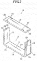
- Fig. 2 is an exploded perspective view of a male trough 10.
- Fig. 3A and 3B are exploded perspective views of a female trough 20.
- the cable trough 100 for corners includes alternatingly coupled male troughs 10 and female troughs 20 (three each in Fig. 1 ).
- the male trough 10 includes a male trough body 13 having a substantially U-shape cross-section and having a first bottom wall 11, and a pair of first side walls 12; and a substantially planar first lid 15 covering the male trough body 13 across the pair of first side walls 12.
- the male trough body 13 and the first lid 15 are composed of a resin material, such as resin containing recycled plastic.
- Bottom protrusions 11a protrude downward from each of the two ends of the bottom face of the first bottom wall 11 of the male trough body 13.
- the top faces of the first side walls 12 are provided with projections 12b for alignment of the first lid 15.
- Lid protrusions 15a protrude upward from each of the two ends of the top face of the first lid 15.
- Engaging chases 15b that engage with the projections 12b of the male trough body 13 (first side walls 12) are disposed at the center of each of the longitudinal ends of the first lid 15.
- the first lid 15 is disposed on the male trough body 13 to assemble the first lid 15 and the male trough body 13 into the male trough 10.
- Each of the bottom protrusions 11a of the first bottom wall 11 of the male trough body 13 has substantially the same shape as each of the lid protrusions 15a of the first lid 15.
- the bottom protrusions 11a and the respective lid protrusions 15a are designed to align in the vertical direction in an assembled state of the male trough 10.
- the female trough 20 includes a female trough body 23 having a substantially U-shaped cross-section and having a second bottom wall 21 and a pair of second side walls 22; a substantially planar second lid 25 covering the female trough body 23 across the pair of second side walls 22; and a lid fixing member 26 that fixes the second lid 25 to the female trough body 23.
- the female trough body 23 and the second lid 25 are composed of a resin material, such as resin containing recycled plastic.
- the lid fixing member 26 is a bent metal plate composed of, for example, stainless steel.
- Bottom depressions 21a into each of which the bottom protrusions 11a of the male trough body 13 are to be inserted are disposed on the upper face of the second bottom wall 21 of the female trough body 23.
- the top faces of the second side walls 22 are provided with engaging recesses 22b for alignment of the second lid 25.
- the upper external faces of the second side walls 22 are provided with engagements 22c that engage with engaging ends 26a of the lid fixing member 26.
- Lid depressions 25a into each of which the lid protrusions 15a of the first lid 15 are to be inserted are disposed on the lower face of the second lid 25 (see Fig. 3B ).
- Projections 25b that engage with the respective engaging recesses 22b of the female trough body 23 are disposed on the lower face of the second lid 15 at the two ends in the longitudinal direction.
- a long groove 25c in which the lid fixing member 26 is to be fixed is formed in the upper face of the second lid 25.
- the second lid 25 is disposed on the female trough body 23 to assemble the second lid 25 and the female trough body 23 into the female trough 20.
- Each of the bottom depressions 21a of the second bottom wall 21 of the female trough body 23 has substantially the same shape as each of the lid depressions 25a of the second lid 25.
- the bottom depressions 21a and the respective lid depressions 25a are designed to align in the vertical direction in an assembled state of the female trough 20.
- the side beams 12a of the male trough body 13 are slid from the top ends of the respective side grooves 22a of the female trough body 23 along the side grooves 22a, to fit the side beams 12a of the male trough body 13 to the side grooves 22a of the female trough body 23.
- the first bottom wall 11 of the male trough body 13 reaches the second bottom wall 21 of the female trough body 23, and the bottom protrusions 11a of the male trough body 13 are inserted into the corresponding bottom depressions 21a of the female trough body 23.
- the male joints 13a are connected with the respective female joints 23a such that they are overlap each other, and thereby the female trough body 23 and the male trough body 13 are coupled to each other.
- Such assembling of the female trough body 23 and the male trough body 13 is repeated to alternatingly couple a predetermined number of female trough bodies 23 and male trough bodies 13.
- First lids 15 are then disposed on the respective male trough bodies 13 into male troughs 10.
- second lids 25 are disposed on the respective female trough bodies 23 into female troughs 20.
- Each second lid 25 is disposed on the corresponding female trough body 23 such that the corresponding lid protrusions 15a of the adjoining first lids 15 are inserted into the lid depressions 25a of the second lid 25.
- the lid fixing member 26 is exactly disposed along the long groove 25c of the second lid 25.
- the engaging ends 26a of the lid fixing member 26 are engaged with the respective engagements 22c of the female trough body 23 to fix the second lid 25 to the female trough body 23.
- the first lids 15 disposed on the male trough bodies 13 are urged by the second lids 25 disposed on the female trough bodies 23.
- the lid fixing members 26 can fix the second lids 25 and the first lids 15 to the female trough bodies 23 and the male trough bodies 13, respectively.
- Assembling the male troughs 10 and the female troughs 20 through such a process can alternatingly couple the male troughs 10 and the female troughs 20 into the cable trough 100 for corners.
- the side beams 12a of the male trough bodies 13 are designed to movably fit with the side grooves 22a of the respective female trough bodies 23 in a coupled state of the male troughs 10 and the female troughs 20.
- the bottom protrusions 11a of the male trough bodies 13 are designed to be movably inserted into the bottom depressions 21a of the respective female trough bodies 23, and the lid protrusions 15a of the first lids 15 are designed to be movably inserted into the lid depressions 25a of the respective second lids 25.
- the side beams 12a and the respective side grooves 22a, the bottom protrusions 11a and the respective bottom depressions 21a, and the lid protrusions 15a and the respective lid depressions 25a movably fit together with each other.
- the relative orientation to each other can be varied while the coupled state of the male troughs 10 and the female troughs 20 is maintained, to bend the cable trough 100 for corners.
- Figs. 4A to 4D are top views of the female trough bodies 23 and the male trough bodies 13 for simplification of the coupling structure of the female troughs 20 and the male troughs 10.
- Fig. 4A is a top view of the female trough body 23 and the male trough body 13.
- the top view of the male trough body 13 is considered transparent for the visualization of the bottom protrusions 11a through the male trough body 13 (this is also the same for Figs. 4B to 4D ).
- the bottom protrusion 11a on the right in the drawing moves toward the center of the corresponding bottom depression 21a, and the bottom protrusion 11a on the left in the drawing comes into contact with the edge of the corresponding bottom depression 21a.
- the lid protrusion 15a on the right moves toward the center of the corresponding lid depression 25a, and the lid protrusion 15a on the left comes into contact with the edge of the corresponding lid depression 25a.
- the orientations of the female trough 20 (the female trough body 23) and the male trough 10 (the male trough body 13) can be varied relative to each other while maintaining the coupled state thereof.
- a cable trough 100 for corners including alternatingly coupled multiple female trough bodies 23 (female troughs 20) and multiple male trough bodies 13 (male troughs 10) (four each in Fig. 4D ), the orientations of the female troughs 20 and the male troughs 10 relative to each other can be varied at the coupling sites, to bend the cable trough 100 for corners, as illustrated in Fig. 4D .
- Such a cable trough 100 for corners can be bent depending on a curvature of a curved route, and placed along the curved route.
- long cable troughs 50 can be coupled and placed in the longitudinal direction along linear routes, whereas the cable troughs 100 for corners can be placed along curved routes and coupled to adjoining cable troughs 50 at the two ends, for example.
- the number of female troughs 20 and male troughs 10 to be coupled can be adjusted in accordance with the curvature (bending angle) of the curved route along which the cable troughs 100 for corners are to be placed. For example, as illustrated in Fig. 5 , the bending angle of the cable trough 100 for corners can be increased by increasing the number of female troughs 20 and the male troughs 10 of the cable trough 100 for corners.
- the bending angle of the cable trough 100 for corners can be adjusted by adjusting the orientations (angles) of the female troughs 20 and the male troughs 10. For example, a small angle between one of the female troughs 20 and the adjacent male trough 10 defines a small bending angle of the cable trough 100 for corners, whereas a large angle between one of the female troughs 20 and the adjacent male trough 10 defines a large bending angle of the cable trough 100 for corners.
- Such a cable trough 100 for corners can be bent in accordance with the curvature (bending angle) of the route along which the cable trough 100 for corners is to be placed, to readily place the cable trough 100 for corners along the curved route.
- the cable trough 100 for corners can be bent toward the left or right along an installation direction of the cable troughs.
- the cable trough 100 for corners can be bent in a vertical direction with respect to an installation direction of the cable troughs.
- the bottom protrusions 11a of the male trough bodies 13 are movably fit with the corresponding bottom depressions 21a of the female trough bodies 23, and the lid protrusions 15a of the first lid 15 are movably fit with the corresponding lid depressions 25a of the second lid 25.
- the movement of the lid protrusions 15a of the first lid 15, which move relative to the first bottom wall 11, is restricted by the corresponding lid depression 25a
- the movement of the bottom protrusions 11a of the first bottom wall 11, which move relative to the first lid 15, is restricted by the corresponding bottom depressions 21a.
- the cable trough 100 for corners can be bent in the vertical direction with respect to the installation direction of the cable troughs.
- the cable trough 100 for corners is an assembly including alternatingly coupled male troughs 10 each having male joints 13a at the two ends and female troughs 20 having female joints 23a at the two ends.
- cable troughs 70 each including a male joint 70a at one end and a female joint 70b at the other end are assembled into an assembly by coupling the male joints 70a and the female joints 70b, and the assembly is compared with the cable trough 100 for corners according to this embodiment.
- the area between the male joint 70a and the female joint 70b of each of the cable troughs 70 is defined as a trough body 70c.
- the cable trough 70 includes a male joint 70a having coupling protrusions 71 and a female joint 70b having coupling depressions 72.
- the coupling protrusions 71 are designed such that the movement of the coupling protrusions 71 is restricted by the respective coupling depressions 72 and the coupling protrusions 71 are movably fit with the respective coupling depressions 72, in a coupled state of the male joint 70a and the female joint 70b.
- Four cable troughs 70 are coupled by inserting the male joints 70a into the respective female joints 70b to form the assembly of the cable troughs 70 illustrated in Fig. 6B .
- the bending angle of the assembly is smaller than that of the cable trough 100 for corners.
- Cable troughs 80 having a larger bending angle in an assembly are also prepared.
- the cable trough 80 includes a male joint 80a having coupling protrusions 81 at one end and a female joint 80b having coupling depressions 82 at the other end.
- the area between the male joint 80a and the female joint 80b of each of the cable troughs 80 is defined as a trough body 80c.
- the cable trough 80 includes a trough body 80c having the same dimensions as those of the trough body 70c of the cable trough 70 and has a total length from the edge of the male joint 80a to the edge of the female joint 80b that is larger than that of the cable trough 70. That is, the cable trough 80 is designed such that, although the movement of the coupling protrusions 81 is restricted by the respective coupling depressions 82, the areas of the coupling depressions 82 within which the coupling protrusions 81 are movable are larger than those in the cable trough 70, in a coupled state of the male joint 80a and the female joint 80b.
- the bending angle of the assembly is larger than that of the assembly of the cable troughs 70 but smaller than that of the cable trough 100 for corners.
- the radius of curvature of the assembly of the cable troughs 80 is larger than that of the cable trough 100 for corners, and the bending angle is smaller than that of the cable trough 100 for corners, as illustrated in Fig. 8 .
- the cable trough 100 for corners including the male troughs 10 each having the male joints 13a at the two ends and the female troughs 20 each having the female joints 23a at the two ends does not reduce the inner space even when it is bent, and can bent at a relatively large bending angle.
- the cable trough 100 for corners including the male troughs 10 each equipped with the male joints 13a at the two ends and the female troughs 20 each equipped with the female joints 23a at the two ends can bend at a relatively large bending angle.
- the cable trough 100 for corners is more advantageous than the assemblies of the cable troughs 70 and 80 each having a male joint at one end and a female joint at the other end.
- the cable trough 100 for corners according to this embodiment can bend at a relatively large bending angle and be readily placed along a curved route.
- the cable trough 100 for corners includes three female troughs 20 and three male troughs 10 alternatingly coupled as illustrated in Fig. 1 , four female troughs 20 and four male troughs 10 alternatingly coupled as illustrated in Fig. 5 , or seven female troughs 20 and seven male troughs 10 alternatingly coupled as illustrated in Fig. 5 .
- the present invention should not be limited to these embodiments, and the cable trough 100 for corners may include any number of female troughs 20 and male troughs 10.
- the present invention having the configuration described above can be suitably used as a cable trough for corners, which is to be placed along a curved route.
Landscapes
- Engineering & Computer Science (AREA)
- Architecture (AREA)
- Civil Engineering (AREA)
- Structural Engineering (AREA)
- Laying Of Electric Cables Or Lines Outside (AREA)
Abstract
Description
- The present invention relates to a cable trough for corners, which trough is installed near a railroad track and the like and suitable for installment along a curved route.
- Heretofore, multiple cable troughs each having a male joint at one end and a female joint at the other end are coupled in a longitudinal direction by inserting the male joint of one of the cable troughs to the female joint of the adjoining cable trough, for installation of the cable troughs in a predetermined area (refer to Patent Document 1, for example).
- In some cases, the cable troughs should be installed along a curved route in a narrow railway land, to circumvent other facilities.
- Curved cable trough products are commercially available. Unfortunately, sometimes their curvatures do not match the route along which the cable trough products are to be installed. In such a case, multiple trough pieces prepared by cutting long cable troughs may be disposed along the curved route with mortar interfilling, for example, provided between the trough pieces.
- Patent Document 1: Japanese Patent Application Laid-Open Publication No.
2009-81995 - As in the conventional art described above, the process of cutting the cable troughs and connecting multiple trough pieces with mortar at a construction site is inefficient and tends to lead to an uneven finish.
- An object of the present invention is to provide a cable trough for corners, which trough can be readily disposed along a curved route.
- To accomplish the above object, there is provided a cable trough for corners including: a male trough body including a first bottom wall, a pair of first side walls, and male joints composed of side beams protruding externally from both edges of an external face of each of the first side walls, a female trough body including a second bottom wall, a pair of second side walls, and female joints composed of side grooves into which the side beams are fitted, respectively, at both edges of an inner face of each of the second side walls, wherein the male trough body and the female trough body are alternatingly coupled to each other by connecting the male joints with the female joints, when one of the first side walls moves to an interior of the female trough body at an angle to the second side walls, a movement of at least one of the side beams of another of the first side walls is restricted by at least one of the side grooves into which the at least one of the side beams is fitted, the another of the first side walls moving relative to the one of the first side walls, when the another of the first side walls moves to the interior of the female trough body at an angle to the second side walls, a movement of at least one of the side beams of the one of the first side walls is restricted by at least one of the side grooves into which the at least one of the side beams is fitted, the one of the first side walls moving relative to the another of the first side walls, and the male trough body and the female trough body are coupled such that an orientation of the male trough body and an orientation of the female trough body are variable relative to each other.
- In the cable trough for corners having such a configuration, the relative orientation between the male trough body and the female trough body can be varied while the coupled state is maintained. Thus, in the cable trough for corners including the male trough body coupled to the female trough body, the relative orientation between the male trough body and the female trough body can be varied at the coupling sites, to bend the cable trough for corners.
- In this way, the cable trough for corners including the male trough body having male joints at the both edges, coupled to the female trough body having female joints at the two ends, by alternatively coupling the male joints and the female joints can be bent by varying the relative orientation between the male trough body and the female trough body at a coupling site.
- Such a cable trough for corners can be readily bent and placed along a curved route to conform to the curvature of the curved route.
- Preferably, the cable trough for corners further includes: a first lid disposed across the pair of first side walls on the male trough body; a second lid disposed across the pair of second side walls on the female trough body, and the first bottom wall has a lower face having bottom protrusions protruding downward from both edges of the lower face, and the second bottom wall has an upper face having a bottom depression into which the bottom protrusions are inserted, the first top lid has an upper face having lid protrusions protruding upward from both edges of the upper face, and the second lid has a lower face having a lid depression into which the lid protrusions are inserted, and the bottom protrusions are movably inserted into the bottom depression, and the lid protrusions are movably inserted into the lid depression.
- In the assembly that includes the male trough including a male trough body and a first lid disposed thereon and the female trough including a female trough body and a second lid disposed thereon, the bottom protrusions are movably inserted into the bottom depression, and the lid protrusions are movably inserted into the lid depression. Thus, the relative orientation can be varied between the male trough body and the female trough body.
- In this way, the cable trough for corners including the first lid disposed on the male trough body and the second lid disposed on the female trough body can be coupled at a bent state.
- Preferably, the cable trough for corners further includes: a lid fixing member which fixes the second lid to the female trough body.
- The first lid disposed on the male trough body is urged by the second lid dispose on the female trough body. Thus, the second lid can be fixed to the female trough body with the lid fixing member such that the first lid is firmly fixed to the male trough body.
- In specific, the second lid and the first lid can be firmly fixed to the female trough body and the male trough body, respectively, with the lid fixing member for fixing the second lid to the female trough body.
- The present invention provides a cable trough for corners, which trough can be readily placed along a curved route.
-
-
Fig. 1 is a perspective view of a cable trough for corners according to an embodiment. -
Fig. 2 is an exploded perspective view of a male trough. -
Fig. 3A is an exploded perspective view of a female trough. -
Fig. 3B is a perspective bottom view of a second lid. -
Fig. 4A is an explanatory drawing of a coupling structure of female and male troughs illustrating top views of female and male trough bodies. -
Fig. 4B is an explanatory drawing of the coupling structure of the female and male troughs illustrating a coupled state of the female and male trough bodies. -
Fig. 4C is an explanatory drawing of the coupling structure of the female and male troughs illustrating a coupled state of the female and male trough bodies where orientations thereof are varied relative to each other. -
Fig. 4D is an explanatory drawing of the coupling structure of female and male troughs illustrating a curved state of the cable trough for corners. -
Fig. 5 is an explanatory drawing of example installation of the cable troughs for corners. -
Fig. 6A is a top view of an example cable trough having a male joint at one end and a female joint at the other end. -
Fig. 6B is an explanatory drawing of an assembly of cable troughs each having a male joint at one end and a female joint at the other end. -
Fig. 7A is a top view of an example cable trough having a male joint at one end and a female joint at the other end. -
Fig. 7B is an explanatory drawing of an assembly of the cable troughs each having the male joint at one end and the female joint at the other end. -
Fig. 8 is an explanatory drawing of a comparison of the cable trough for corners according to the embodiment and the assembly of the cable troughs illustrated inFig. 7B . - A cable trough for corners according to embodiments of the present invention will now be described in detail with reference to the accompanying drawings. The following embodiments and the attached drawings feature various technically preferred configurations for accomplishing the present invention. The scope of the invention, however, should not be limited to the embodiments and drawings.
-
Fig. 1 is a perspective view of acable trough 100 for corners.Fig. 2 is an exploded perspective view of amale trough 10.Fig. 3A and 3B are exploded perspective views of afemale trough 20. - With reference to
Fig. 1 , thecable trough 100 for corners according to this embodiment includes alternatingly coupledmale troughs 10 and female troughs 20 (three each inFig. 1 ). - With reference to
Figs. 1 and2 , themale trough 10 includes a maletrough body 13 having a substantially U-shape cross-section and having afirst bottom wall 11, and a pair offirst side walls 12; and a substantially planarfirst lid 15 covering the maletrough body 13 across the pair offirst side walls 12. - The
male trough body 13 and thefirst lid 15 are composed of a resin material, such as resin containing recycled plastic. -
Bottom protrusions 11a protrude downward from each of the two ends of the bottom face of thefirst bottom wall 11 of themale trough body 13. -
Side beams 12a protrude externally from the two edges of the external face of each of thefirst side walls 12 of themale trough body 13. - The two substantially U-shaped peripheries of the
male trough body 13, which include thebottom protrusions 11a and theside beams 12a, function asmale joints - The top faces of the
first side walls 12 are provided withprojections 12b for alignment of thefirst lid 15. -
Lid protrusions 15a protrude upward from each of the two ends of the top face of thefirst lid 15. - Engaging
chases 15b that engage with theprojections 12b of the male trough body 13 (first side walls 12) are disposed at the center of each of the longitudinal ends of thefirst lid 15. - The
first lid 15 is disposed on themale trough body 13 to assemble thefirst lid 15 and themale trough body 13 into themale trough 10. - Each of the
bottom protrusions 11a of thefirst bottom wall 11 of themale trough body 13 has substantially the same shape as each of thelid protrusions 15a of thefirst lid 15. Thebottom protrusions 11a and therespective lid protrusions 15a are designed to align in the vertical direction in an assembled state of themale trough 10. - With reference to
Figs. 1 ,3A, and 3B , thefemale trough 20 includes afemale trough body 23 having a substantially U-shaped cross-section and having asecond bottom wall 21 and a pair ofsecond side walls 22; a substantially planarsecond lid 25 covering thefemale trough body 23 across the pair ofsecond side walls 22; and alid fixing member 26 that fixes thesecond lid 25 to thefemale trough body 23. - The
female trough body 23 and thesecond lid 25 are composed of a resin material, such as resin containing recycled plastic. - The
lid fixing member 26 is a bent metal plate composed of, for example, stainless steel. -
Bottom depressions 21a into each of which thebottom protrusions 11a of themale trough body 13 are to be inserted are disposed on the upper face of thesecond bottom wall 21 of thefemale trough body 23. -
Side grooves 22a into each of which theside beams 12a of themale trough body 13 are to be fitted are disposed at both edges of each of the inner faces of the twosecond side walls 22 of thefemale trough body 23. - The two substantially U-shaped peripheries of the
female trough body 23, which include the edges of thebottom depressions 21a and theside grooves 22a, function asfemale joints - The top faces of the
second side walls 22 are provided with engagingrecesses 22b for alignment of thesecond lid 25. - The upper external faces of the
second side walls 22 are provided withengagements 22c that engage with engagingends 26a of thelid fixing member 26. -
Lid depressions 25a into each of which thelid protrusions 15a of thefirst lid 15 are to be inserted are disposed on the lower face of the second lid 25 (seeFig. 3B ). -
Projections 25b that engage with the respective engagingrecesses 22b of the female trough body 23 (respective second side walls 22) are disposed on the lower face of thesecond lid 15 at the two ends in the longitudinal direction. - A
long groove 25c in which thelid fixing member 26 is to be fixed is formed in the upper face of thesecond lid 25. - The
second lid 25 is disposed on thefemale trough body 23 to assemble thesecond lid 25 and thefemale trough body 23 into thefemale trough 20. - Each of the
bottom depressions 21a of thesecond bottom wall 21 of thefemale trough body 23 has substantially the same shape as each of thelid depressions 25a of thesecond lid 25. Thebottom depressions 21a and therespective lid depressions 25a are designed to align in the vertical direction in an assembled state of thefemale trough 20. - The process of coupling the
male trough 10 and thefemale trough 20 will now be described. - The side beams 12a of the
male trough body 13 are slid from the top ends of therespective side grooves 22a of thefemale trough body 23 along theside grooves 22a, to fit theside beams 12a of themale trough body 13 to theside grooves 22a of thefemale trough body 23. - The
first bottom wall 11 of themale trough body 13 reaches thesecond bottom wall 21 of thefemale trough body 23, and thebottom protrusions 11a of themale trough body 13 are inserted into the correspondingbottom depressions 21a of thefemale trough body 23. - In this way, the
male joints 13a are connected with the respectivefemale joints 23a such that they are overlap each other, and thereby thefemale trough body 23 and themale trough body 13 are coupled to each other. - Such assembling of the
female trough body 23 and themale trough body 13 is repeated to alternatingly couple a predetermined number offemale trough bodies 23 andmale trough bodies 13. -
First lids 15 are then disposed on the respectivemale trough bodies 13 intomale troughs 10. - After the
first lids 15 are disposed on all of themale trough bodies 13,second lids 25 are disposed on the respectivefemale trough bodies 23 intofemale troughs 20. Eachsecond lid 25 is disposed on the correspondingfemale trough body 23 such that the correspondinglid protrusions 15a of the adjoiningfirst lids 15 are inserted into thelid depressions 25a of thesecond lid 25. - The
lid fixing member 26 is exactly disposed along thelong groove 25c of thesecond lid 25. The engaging ends 26a of thelid fixing member 26 are engaged with therespective engagements 22c of thefemale trough body 23 to fix thesecond lid 25 to thefemale trough body 23. - The
male joints 13a (thebottom protrusions 11a and theside beams 12a) of themale trough 10 fit with thefemale joints 23a (thebottom depressions 21a and theside grooves 22a) of the adjoiningfemale troughs 20. Thelid protrusions 15a of thefirst lids 15 of themale troughs 10 fit with thelid depressions 25a of thesecond lids 25 of the adjoiningfemale troughs 20. Thefirst lids 15 disposed on themale trough bodies 13 are urged by thesecond lids 25 disposed on thefemale trough bodies 23. - Since the
second lids 25 are fixed to thefemale trough bodies 23 with thelid fixing members 26, thefirst lids 15 are firmly fixed to themale trough bodies 13. In specific, thelid fixing members 26 can fix thesecond lids 25 and thefirst lids 15 to thefemale trough bodies 23 and themale trough bodies 13, respectively. - Assembling the
male troughs 10 and thefemale troughs 20 through such a process can alternatingly couple themale troughs 10 and thefemale troughs 20 into thecable trough 100 for corners. - The side beams 12a of the
male trough bodies 13 are designed to movably fit with theside grooves 22a of the respectivefemale trough bodies 23 in a coupled state of themale troughs 10 and thefemale troughs 20. - Similarly, the
bottom protrusions 11a of themale trough bodies 13 are designed to be movably inserted into thebottom depressions 21a of the respectivefemale trough bodies 23, and thelid protrusions 15a of thefirst lids 15 are designed to be movably inserted into thelid depressions 25a of the respectivesecond lids 25. - In this way, the
side beams 12a and therespective side grooves 22a, thebottom protrusions 11a and the respectivebottom depressions 21a, and thelid protrusions 15a and therespective lid depressions 25a movably fit together with each other. Thus, the relative orientation to each other can be varied while the coupled state of themale troughs 10 and thefemale troughs 20 is maintained, to bend thecable trough 100 for corners. - The bending mechanism of the
cable trough 100 for corners will now be described with reference toFigs. 4A to 4D . -
Figs. 4A to 4D are top views of thefemale trough bodies 23 and themale trough bodies 13 for simplification of the coupling structure of thefemale troughs 20 and themale troughs 10. - Since the movement of the
lid protrusions 15a of thefirst lid 15 coincide with the movement of thebottom protrusions 11a of themale trough body 13, and the movement of thelid depressions 25a of thesecond lid 25 coincides with the movement of thebottom depressions 21a of thefemale trough body 23, the correspondence of the movements of these components is described. -
Fig. 4A is a top view of thefemale trough body 23 and themale trough body 13. - The top view of the
male trough body 13 is considered transparent for the visualization of thebottom protrusions 11a through the male trough body 13 (this is also the same forFigs. 4B to 4D ). - With reference to
Fig. 4B , when theside grooves 22a of thefemale trough body 23 fit with therespective side beams 12a of themale trough body 13 to couple thefemale troughs 20 and themale troughs 10, thebottom protrusions 11a of themale trough body 13 are inserted into the correspondingbottom depressions 21a of thefemale trough body 23. Although not shown, thelid protrusions 15a of thefirst lid 15 are inserted into the correspondinglid depressions 25a of thesecond lid 25. - With reference to
Fig. 4C , when one first side wall 12 (thefirst side wall 12 on the right in the drawing) moves to the interior of thefemale trough body 23 at an angle to thesecond side walls 22, the movement of theside beam 12a of the other first side wall 12 (thefirst side wall 12 on the left in the drawing), which moves relative to the onefirst side wall 12, is restricted by thecorresponding side groove 22a. - At this time, the
bottom protrusion 11a on the right in the drawing moves toward the center of the correspondingbottom depression 21a, and thebottom protrusion 11a on the left in the drawing comes into contact with the edge of the correspondingbottom depression 21a. Although not illustrated, thelid protrusion 15a on the right moves toward the center of thecorresponding lid depression 25a, and thelid protrusion 15a on the left comes into contact with the edge of thecorresponding lid depression 25a. - Similarly, when the other first side wall 12 (the
first side wall 12 on the left in the drawing) moves to the interior of thefemale trough body 23 at an angle to thesecond side walls 22, the movement of theside beam 12a of the one first side wall 12 (thefirst side wall 12 on the right in the drawing), which moves relative to the otherfirst side wall 12, is restricted by thecorresponding side groove 22a. - In this way, the orientations of the female trough 20 (the female trough body 23) and the male trough 10 (the male trough body 13) can be varied relative to each other while maintaining the coupled state thereof.
- In a
cable trough 100 for corners including alternatingly coupled multiple female trough bodies 23 (female troughs 20) and multiple male trough bodies 13 (male troughs 10) (four each inFig. 4D ), the orientations of thefemale troughs 20 and themale troughs 10 relative to each other can be varied at the coupling sites, to bend thecable trough 100 for corners, as illustrated inFig. 4D . - Such a
cable trough 100 for corners can be bent depending on a curvature of a curved route, and placed along the curved route. - As illustrated in
Fig. 5 ,long cable troughs 50 can be coupled and placed in the longitudinal direction along linear routes, whereas thecable troughs 100 for corners can be placed along curved routes and coupled to adjoiningcable troughs 50 at the two ends, for example. - The number of
female troughs 20 andmale troughs 10 to be coupled can be adjusted in accordance with the curvature (bending angle) of the curved route along which thecable troughs 100 for corners are to be placed. For example, as illustrated inFig. 5 , the bending angle of thecable trough 100 for corners can be increased by increasing the number offemale troughs 20 and themale troughs 10 of thecable trough 100 for corners. - Even with the same number of
female troughs 20 andmale troughs 10 of thecable trough 100 for corners, the bending angle of thecable trough 100 for corners can be adjusted by adjusting the orientations (angles) of thefemale troughs 20 and themale troughs 10. For example, a small angle between one of thefemale troughs 20 and the adjacentmale trough 10 defines a small bending angle of thecable trough 100 for corners, whereas a large angle between one of thefemale troughs 20 and the adjacentmale trough 10 defines a large bending angle of thecable trough 100 for corners. - Such a
cable trough 100 for corners according to this embodiment can be bent in accordance with the curvature (bending angle) of the route along which thecable trough 100 for corners is to be placed, to readily place thecable trough 100 for corners along the curved route. - In the embodiment described above, when one first side wall 12 (the
first side wall 12 on the right in the drawing) moves to the interior of thefemale trough body 23 at an angle to thesecond side walls 22, the movement of theside beam 12a of the other first side wall 12 (thefirst side wall 12 on the left in the drawing), which moves relative to the otherfirst side wall 12, is restricted by thecorresponding side groove 22a, and when the other first side wall 12 (thefirst side wall 12 on the left in the drawing) moves to the interior of thefemale trough body 23 at an angle to thesecond side walls 22, the movement of theside beam 12a of the one first side wall 12 (thefirst side wall 12 on the right in the drawing), which moves relative to the otherfirst side wall 12, is restricted by thecorresponding side groove 22a. Thus, thecable trough 100 for corners can be bent toward the left or right along an installation direction of the cable troughs. In addition, thecable trough 100 for corners can be bent in a vertical direction with respect to an installation direction of the cable troughs. - As described above, the
bottom protrusions 11a of themale trough bodies 13 are movably fit with the correspondingbottom depressions 21a of thefemale trough bodies 23, and thelid protrusions 15a of thefirst lid 15 are movably fit with the correspondinglid depressions 25a of thesecond lid 25. - When the
first bottom wall 11 moves to the interior of thefemale trough body 23 at an angle to the secondbottom walls 21, the movement of thelid protrusions 15a of thefirst lid 15, which move relative to thefirst bottom wall 11, is restricted by the correspondinglid depression 25a, and when thefirst lid 15 moves to the interior of thefemale trough body 23 at an angle to thesecond lid 25, the movement of thebottom protrusions 11a of thefirst bottom wall 11, which move relative to thefirst lid 15, is restricted by the correspondingbottom depressions 21a. In such a configuration, thecable trough 100 for corners can be bent in the vertical direction with respect to the installation direction of the cable troughs. - When the
cable trough 100 for corners is bent in the vertical direction with respect to the installation direction of the cable troughs, the upper and lower edges of theside beams 12a, which fit with thecorresponding side grooves 22a, come into contact with thecorresponding side grooves 22a so as to restrict the movement of theside beams 12a. - The advantageous effect of the
cable trough 100 for corners according to this embodiment as a bendable assembly will be described. - As described above, the
cable trough 100 for corners is an assembly including alternatingly coupledmale troughs 10 each havingmale joints 13a at the two ends andfemale troughs 20 havingfemale joints 23a at the two ends. - In contrast,
cable troughs 70 each including a male joint 70a at one end and a female joint 70b at the other end are assembled into an assembly by coupling themale joints 70a and thefemale joints 70b, and the assembly is compared with thecable trough 100 for corners according to this embodiment. - The area between the male joint 70a and the female joint 70b of each of the
cable troughs 70 is defined as a trough body 70c. - With reference to
Fig. 6A , thecable trough 70 includes a male joint 70a havingcoupling protrusions 71 and a female joint 70b havingcoupling depressions 72. The coupling protrusions 71 are designed such that the movement of thecoupling protrusions 71 is restricted by therespective coupling depressions 72 and thecoupling protrusions 71 are movably fit with therespective coupling depressions 72, in a coupled state of the male joint 70a and the female joint 70b. - Four
cable troughs 70 are coupled by inserting themale joints 70a into the respectivefemale joints 70b to form the assembly of thecable troughs 70 illustrated inFig. 6B . The bending angle of the assembly is smaller than that of thecable trough 100 for corners. -
Cable troughs 80 having a larger bending angle in an assembly are also prepared. - With reference to
Fig. 7A , thecable trough 80 includes a male joint 80a havingcoupling protrusions 81 at one end and a female joint 80b havingcoupling depressions 82 at the other end. The area between the male joint 80a and the female joint 80b of each of thecable troughs 80 is defined as a trough body 80c. - The
cable trough 80 includes a trough body 80c having the same dimensions as those of the trough body 70c of thecable trough 70 and has a total length from the edge of the male joint 80a to the edge of the female joint 80b that is larger than that of thecable trough 70. That is, thecable trough 80 is designed such that, although the movement of thecoupling protrusions 81 is restricted by therespective coupling depressions 82, the areas of thecoupling depressions 82 within which thecoupling protrusions 81 are movable are larger than those in thecable trough 70, in a coupled state of the male joint 80a and the female joint 80b. - Four
cable troughs 80 are coupled by inserting themale joints 80a into the respectivefemale joints 80b to form the assembly of thecable troughs 80 illustrated inFig. 7B . The bending angle of the assembly is larger than that of the assembly of thecable troughs 70 but smaller than that of thecable trough 100 for corners. In specific, the radius of curvature of the assembly of thecable troughs 80 is larger than that of thecable trough 100 for corners, and the bending angle is smaller than that of thecable trough 100 for corners, as illustrated inFig. 8 . - It has been discovered that when bending the assembly of the
cable troughs 80 each having a total length larger than that of thecable trough 70, the inner corners of themale joints 80a protrude to the interior of therespective cable troughs 80 and reduce the inner space of thecable troughs 80, as illustrated in the dashed circles inFig. 7B . The cables disposed inside thecable troughs 70 might even be damaged by the inner corners of themale joints 80a that protrude to the interior. - In contrast, the
cable trough 100 for corners including themale troughs 10 each having themale joints 13a at the two ends and thefemale troughs 20 each having thefemale joints 23a at the two ends does not reduce the inner space even when it is bent, and can bent at a relatively large bending angle. - In this way, the
cable trough 100 for corners including themale troughs 10 each equipped with themale joints 13a at the two ends and thefemale troughs 20 each equipped with thefemale joints 23a at the two ends can bend at a relatively large bending angle. Thus, thecable trough 100 for corners is more advantageous than the assemblies of thecable troughs - As described above, the
cable trough 100 for corners according to this embodiment can bend at a relatively large bending angle and be readily placed along a curved route. - In the embodiments described above, the
cable trough 100 for corners includes threefemale troughs 20 and threemale troughs 10 alternatingly coupled as illustrated inFig. 1 , fourfemale troughs 20 and fourmale troughs 10 alternatingly coupled as illustrated inFig. 5 , or sevenfemale troughs 20 and sevenmale troughs 10 alternatingly coupled as illustrated inFig. 5 . The present invention should not be limited to these embodiments, and thecable trough 100 for corners may include any number offemale troughs 20 andmale troughs 10. - The detailed configuration may be appropriately modified without departing from the scope of the present invention.
- The present invention having the configuration described above can be suitably used as a cable trough for corners, which is to be placed along a curved route.
-
- 10
- male trough
- 11
- first bottom wall
- 11a
- bottom protrusion
- 12
- first side wall
- 12a
- side beam
- 12b
- projection
- 13
- male trough body
- 13a
- male joint
- 15
- first lid
- 15a
- lid protrusion
- 15b
- engaging chase
- 20
- female trough
- 21
- second bottom wall
- 21a
- bottom depression
- 22
- second side wall
- 22a
- side groove
- 22b
- engaging recess
- 22c
- engagement
- 23
- female trough body
- 23a
- female joint
- 25
- second lid
- 25a
- lid depression
- 25b
- projection
- 25c
- long groove
- 26
- lid fixing member
- 26a
- engaging end
- 100
- cable trough for corners
Claims (3)
- A cable trough for corners, comprising:a male trough body including a first bottom wall, a pair of first side walls, and male joints composed of side beams protruding externally from both edges of an external face of each of the first side walls,a female trough body including a second bottom wall, a pair of second side walls, and female joints composed of side grooves into which the side beams are fitted, respectively, at both edges of an inner face of each of the second side walls, whereinthe male trough body and the female trough body are alternatingly coupled to each other by connecting the male joints with the female joints,when one of the first side walls moves to an interior of the female trough body at an angle to the second side walls, a movement of at least one of the side beams of another of the first side walls is restricted by at least one of the side grooves into which the at least one of the side beams is fitted, the another of the first side walls moving relative to the one of the first side walls,when the another of the first side walls moves to the interior of the female trough body at an angle to the second side walls, a movement of at least one of the side beams of the one of the first side walls is restricted by at least one of the side grooves into which the at least one of the side beams is fitted, the one of the first side walls moving relative to the another of the first side walls, andthe male trough body and the female trough body are coupled such that an orientation of the male trough body and an orientation of the female trough body are variable relative to each other.
- The cable trough for corners according to claim 1, further comprising:a first lid disposed across the pair of first side walls on the male trough body;a second lid disposed across the pair of second side walls on the female trough body, wherein,the first bottom wall has a lower face having bottom protrusions protruding downward from both edges of the lower face, and the second bottom wall has an upper face having a bottom depression into which the bottom protrusions are inserted,the first top lid has an upper face having lid protrusions protruding upward from both edges of the upper face, and the second lid has a lower face having a lid depression into which the lid protrusions are inserted, andthe bottom protrusions movably are inserted into the bottom depression, and the lid protrusions are movably inserted into the lid depression.
- The cable trough for corners according to claim 2, further comprising:a lid fixing member which fixes the second lid to the female trough body.
Applications Claiming Priority (2)
| Application Number | Priority Date | Filing Date | Title |
|---|---|---|---|
| JP2015028128 | 2015-02-17 | ||
| PCT/JP2016/054293 WO2016133046A1 (en) | 2015-02-17 | 2016-02-15 | Cable trough for corners |
Publications (3)
| Publication Number | Publication Date |
|---|---|
| EP3261206A1 true EP3261206A1 (en) | 2017-12-27 |
| EP3261206A4 EP3261206A4 (en) | 2018-09-26 |
| EP3261206B1 EP3261206B1 (en) | 2021-06-16 |
Family
ID=56688869
Family Applications (1)
| Application Number | Title | Priority Date | Filing Date |
|---|---|---|---|
| EP16752432.1A Active EP3261206B1 (en) | 2015-02-17 | 2016-02-15 | Cable trough for corners |
Country Status (3)
| Country | Link |
|---|---|
| EP (1) | EP3261206B1 (en) |
| JP (1) | JP6644050B2 (en) |
| WO (1) | WO2016133046A1 (en) |
Family Cites Families (5)
| Publication number | Priority date | Publication date | Assignee | Title |
|---|---|---|---|---|
| JPH0724904Y2 (en) * | 1991-07-31 | 1995-06-05 | 日東工業株式会社 | Cable laying member |
| JPH06284544A (en) * | 1993-03-31 | 1994-10-07 | Idemitsu Petrochem Co Ltd | Trough made of synthetic resin |
| US6585195B2 (en) * | 2001-04-25 | 2003-07-01 | Adc Telecommunications, Inc. | Cable management system including variable segments |
| DE202006006756U1 (en) * | 2006-04-26 | 2006-07-06 | Bürcher, Friedrich | Merged channel units e.g. bending units, for formation of closed channel, have inserting and closure parts with ring openings and slots, which enable engagement of units below overlapping breadth that is different at circumference of parts |
| JP5684202B2 (en) * | 2012-06-29 | 2015-03-11 | 古河電気工業株式会社 | Trough and trough connection structure and trough connection method |
-
2016
- 2016-02-15 JP JP2017500664A patent/JP6644050B2/en active Active
- 2016-02-15 EP EP16752432.1A patent/EP3261206B1/en active Active
- 2016-02-15 WO PCT/JP2016/054293 patent/WO2016133046A1/en not_active Ceased
Also Published As
| Publication number | Publication date |
|---|---|
| JP6644050B2 (en) | 2020-02-12 |
| WO2016133046A1 (en) | 2016-08-25 |
| JPWO2016133046A1 (en) | 2018-01-18 |
| EP3261206B1 (en) | 2021-06-16 |
| EP3261206A4 (en) | 2018-09-26 |
Similar Documents
| Publication | Publication Date | Title |
|---|---|---|
| US11028588B2 (en) | Rebar coupler | |
| US9334642B1 (en) | Connection structure of column and beam, and reinforcing member | |
| US3221466A (en) | Dual purpose interlocking beam connectors | |
| US9209609B2 (en) | Cable tray system with splice plate | |
| RU168934U1 (en) | CARBON DEVICE CONNECTION DEVICE WITH RIDGE BEAM | |
| US20230120217A1 (en) | Spliced Wall Panel | |
| CN101198753A (en) | Improved main tee connection | |
| JP2014011881A (en) | Trough, connection structure for troughs, and connection method of troughs | |
| JP4879827B2 (en) | Buckling restraint brace | |
| EP3449065B1 (en) | Improved system for coupling two prefabricated panels for construction | |
| CN101484376B (en) | Structure for joining panels of elevator car | |
| EP3261206B1 (en) | Cable trough for corners | |
| US9400011B2 (en) | Motion device | |
| EP2975717B1 (en) | Trough, method for laying trough, and method for adjusting laying length of trough track | |
| CN107407374A (en) | cable chain | |
| RU2016121224A (en) | HEAT EXCHANGER WITH A SURROUND SEALING ELEMENT | |
| NL1041856B1 (en) | Panels Spilce Connector for Linear Panels. | |
| JP5901727B2 (en) | Trough and trough connection structure | |
| JP2016012998A (en) | Volume expansion structure for cable trough | |
| JP4393775B2 (en) | Long object storage member connector and long object storage device using the connector | |
| KR20170002780U (en) | Joint for connecting square pipe | |
| AU733172B2 (en) | Buried wall case | |
| JP5220796B2 (en) | Trough structure and its laying method | |
| KR101932758B1 (en) | Window frame provided with glass fixing member | |
| GB2121848A (en) | Wall studs and connectors therefor |
Legal Events
| Date | Code | Title | Description |
|---|---|---|---|
| STAA | Information on the status of an ep patent application or granted ep patent |
Free format text: STATUS: THE INTERNATIONAL PUBLICATION HAS BEEN MADE |
|
| PUAI | Public reference made under article 153(3) epc to a published international application that has entered the european phase |
Free format text: ORIGINAL CODE: 0009012 |
|
| STAA | Information on the status of an ep patent application or granted ep patent |
Free format text: STATUS: REQUEST FOR EXAMINATION WAS MADE |
|
| 17P | Request for examination filed |
Effective date: 20170809 |
|
| AK | Designated contracting states |
Kind code of ref document: A1 Designated state(s): AL AT BE BG CH CY CZ DE DK EE ES FI FR GB GR HR HU IE IS IT LI LT LU LV MC MK MT NL NO PL PT RO RS SE SI SK SM TR |
|
| AX | Request for extension of the european patent |
Extension state: BA ME |
|
| DAV | Request for validation of the european patent (deleted) | ||
| DAX | Request for extension of the european patent (deleted) | ||
| A4 | Supplementary search report drawn up and despatched |
Effective date: 20180828 |
|
| RIC1 | Information provided on ipc code assigned before grant |
Ipc: H02G 9/04 20060101AFI20180822BHEP |
|
| STAA | Information on the status of an ep patent application or granted ep patent |
Free format text: STATUS: EXAMINATION IS IN PROGRESS |
|
| 17Q | First examination report despatched |
Effective date: 20200204 |
|
| GRAP | Despatch of communication of intention to grant a patent |
Free format text: ORIGINAL CODE: EPIDOSNIGR1 |
|
| STAA | Information on the status of an ep patent application or granted ep patent |
Free format text: STATUS: GRANT OF PATENT IS INTENDED |
|
| INTG | Intention to grant announced |
Effective date: 20210114 |
|
| GRAS | Grant fee paid |
Free format text: ORIGINAL CODE: EPIDOSNIGR3 |
|
| GRAA | (expected) grant |
Free format text: ORIGINAL CODE: 0009210 |
|
| STAA | Information on the status of an ep patent application or granted ep patent |
Free format text: STATUS: THE PATENT HAS BEEN GRANTED |
|
| AK | Designated contracting states |
Kind code of ref document: B1 Designated state(s): AL AT BE BG CH CY CZ DE DK EE ES FI FR GB GR HR HU IE IS IT LI LT LU LV MC MK MT NL NO PL PT RO RS SE SI SK SM TR |
|
| REG | Reference to a national code |
Ref country code: GB Ref legal event code: FG4D |
|
| REG | Reference to a national code |
Ref country code: CH Ref legal event code: EP |
|
| REG | Reference to a national code |
Ref country code: DE Ref legal event code: R096 Ref document number: 602016059388 Country of ref document: DE |
|
| REG | Reference to a national code |
Ref country code: AT Ref legal event code: REF Ref document number: 1403126 Country of ref document: AT Kind code of ref document: T Effective date: 20210715 |
|
| REG | Reference to a national code |
Ref country code: IE Ref legal event code: FG4D |
|
| REG | Reference to a national code |
Ref country code: LT Ref legal event code: MG9D |
|
| PG25 | Lapsed in a contracting state [announced via postgrant information from national office to epo] |
Ref country code: HR Free format text: LAPSE BECAUSE OF FAILURE TO SUBMIT A TRANSLATION OF THE DESCRIPTION OR TO PAY THE FEE WITHIN THE PRESCRIBED TIME-LIMIT Effective date: 20210616 Ref country code: BG Free format text: LAPSE BECAUSE OF FAILURE TO SUBMIT A TRANSLATION OF THE DESCRIPTION OR TO PAY THE FEE WITHIN THE PRESCRIBED TIME-LIMIT Effective date: 20210916 Ref country code: LT Free format text: LAPSE BECAUSE OF FAILURE TO SUBMIT A TRANSLATION OF THE DESCRIPTION OR TO PAY THE FEE WITHIN THE PRESCRIBED TIME-LIMIT Effective date: 20210616 Ref country code: FI Free format text: LAPSE BECAUSE OF FAILURE TO SUBMIT A TRANSLATION OF THE DESCRIPTION OR TO PAY THE FEE WITHIN THE PRESCRIBED TIME-LIMIT Effective date: 20210616 |
|
| REG | Reference to a national code |
Ref country code: AT Ref legal event code: MK05 Ref document number: 1403126 Country of ref document: AT Kind code of ref document: T Effective date: 20210616 |
|
| REG | Reference to a national code |
Ref country code: NL Ref legal event code: MP Effective date: 20210616 |
|
| PG25 | Lapsed in a contracting state [announced via postgrant information from national office to epo] |
Ref country code: LV Free format text: LAPSE BECAUSE OF FAILURE TO SUBMIT A TRANSLATION OF THE DESCRIPTION OR TO PAY THE FEE WITHIN THE PRESCRIBED TIME-LIMIT Effective date: 20210616 Ref country code: GR Free format text: LAPSE BECAUSE OF FAILURE TO SUBMIT A TRANSLATION OF THE DESCRIPTION OR TO PAY THE FEE WITHIN THE PRESCRIBED TIME-LIMIT Effective date: 20210917 Ref country code: RS Free format text: LAPSE BECAUSE OF FAILURE TO SUBMIT A TRANSLATION OF THE DESCRIPTION OR TO PAY THE FEE WITHIN THE PRESCRIBED TIME-LIMIT Effective date: 20210616 Ref country code: SE Free format text: LAPSE BECAUSE OF FAILURE TO SUBMIT A TRANSLATION OF THE DESCRIPTION OR TO PAY THE FEE WITHIN THE PRESCRIBED TIME-LIMIT Effective date: 20210616 Ref country code: NO Free format text: LAPSE BECAUSE OF FAILURE TO SUBMIT A TRANSLATION OF THE DESCRIPTION OR TO PAY THE FEE WITHIN THE PRESCRIBED TIME-LIMIT Effective date: 20210916 |
|
| PG25 | Lapsed in a contracting state [announced via postgrant information from national office to epo] |
Ref country code: SK Free format text: LAPSE BECAUSE OF FAILURE TO SUBMIT A TRANSLATION OF THE DESCRIPTION OR TO PAY THE FEE WITHIN THE PRESCRIBED TIME-LIMIT Effective date: 20210616 Ref country code: SM Free format text: LAPSE BECAUSE OF FAILURE TO SUBMIT A TRANSLATION OF THE DESCRIPTION OR TO PAY THE FEE WITHIN THE PRESCRIBED TIME-LIMIT Effective date: 20210616 Ref country code: CZ Free format text: LAPSE BECAUSE OF FAILURE TO SUBMIT A TRANSLATION OF THE DESCRIPTION OR TO PAY THE FEE WITHIN THE PRESCRIBED TIME-LIMIT Effective date: 20210616 Ref country code: EE Free format text: LAPSE BECAUSE OF FAILURE TO SUBMIT A TRANSLATION OF THE DESCRIPTION OR TO PAY THE FEE WITHIN THE PRESCRIBED TIME-LIMIT Effective date: 20210616 Ref country code: PT Free format text: LAPSE BECAUSE OF FAILURE TO SUBMIT A TRANSLATION OF THE DESCRIPTION OR TO PAY THE FEE WITHIN THE PRESCRIBED TIME-LIMIT Effective date: 20211018 Ref country code: NL Free format text: LAPSE BECAUSE OF FAILURE TO SUBMIT A TRANSLATION OF THE DESCRIPTION OR TO PAY THE FEE WITHIN THE PRESCRIBED TIME-LIMIT Effective date: 20210616 Ref country code: RO Free format text: LAPSE BECAUSE OF FAILURE TO SUBMIT A TRANSLATION OF THE DESCRIPTION OR TO PAY THE FEE WITHIN THE PRESCRIBED TIME-LIMIT Effective date: 20210616 Ref country code: ES Free format text: LAPSE BECAUSE OF FAILURE TO SUBMIT A TRANSLATION OF THE DESCRIPTION OR TO PAY THE FEE WITHIN THE PRESCRIBED TIME-LIMIT Effective date: 20210616 Ref country code: AT Free format text: LAPSE BECAUSE OF FAILURE TO SUBMIT A TRANSLATION OF THE DESCRIPTION OR TO PAY THE FEE WITHIN THE PRESCRIBED TIME-LIMIT Effective date: 20210616 |
|
| PG25 | Lapsed in a contracting state [announced via postgrant information from national office to epo] |
Ref country code: PL Free format text: LAPSE BECAUSE OF FAILURE TO SUBMIT A TRANSLATION OF THE DESCRIPTION OR TO PAY THE FEE WITHIN THE PRESCRIBED TIME-LIMIT Effective date: 20210616 |
|
| REG | Reference to a national code |
Ref country code: DE Ref legal event code: R097 Ref document number: 602016059388 Country of ref document: DE |
|
| PLBE | No opposition filed within time limit |
Free format text: ORIGINAL CODE: 0009261 |
|
| STAA | Information on the status of an ep patent application or granted ep patent |
Free format text: STATUS: NO OPPOSITION FILED WITHIN TIME LIMIT |
|
| PG25 | Lapsed in a contracting state [announced via postgrant information from national office to epo] |
Ref country code: DK Free format text: LAPSE BECAUSE OF FAILURE TO SUBMIT A TRANSLATION OF THE DESCRIPTION OR TO PAY THE FEE WITHIN THE PRESCRIBED TIME-LIMIT Effective date: 20210616 |
|
| 26N | No opposition filed |
Effective date: 20220317 |
|
| PG25 | Lapsed in a contracting state [announced via postgrant information from national office to epo] |
Ref country code: AL Free format text: LAPSE BECAUSE OF FAILURE TO SUBMIT A TRANSLATION OF THE DESCRIPTION OR TO PAY THE FEE WITHIN THE PRESCRIBED TIME-LIMIT Effective date: 20210616 |
|
| PG25 | Lapsed in a contracting state [announced via postgrant information from national office to epo] |
Ref country code: IT Free format text: LAPSE BECAUSE OF FAILURE TO SUBMIT A TRANSLATION OF THE DESCRIPTION OR TO PAY THE FEE WITHIN THE PRESCRIBED TIME-LIMIT Effective date: 20210616 |
|
| PG25 | Lapsed in a contracting state [announced via postgrant information from national office to epo] |
Ref country code: MC Free format text: LAPSE BECAUSE OF FAILURE TO SUBMIT A TRANSLATION OF THE DESCRIPTION OR TO PAY THE FEE WITHIN THE PRESCRIBED TIME-LIMIT Effective date: 20210616 |
|
| REG | Reference to a national code |
Ref country code: CH Ref legal event code: PL |
|
| REG | Reference to a national code |
Ref country code: BE Ref legal event code: MM Effective date: 20220228 |
|
| PG25 | Lapsed in a contracting state [announced via postgrant information from national office to epo] |
Ref country code: LU Free format text: LAPSE BECAUSE OF NON-PAYMENT OF DUE FEES Effective date: 20220215 |
|
| PG25 | Lapsed in a contracting state [announced via postgrant information from national office to epo] |
Ref country code: FR Free format text: LAPSE BECAUSE OF NON-PAYMENT OF DUE FEES Effective date: 20220228 |
|
| PG25 | Lapsed in a contracting state [announced via postgrant information from national office to epo] |
Ref country code: LI Free format text: LAPSE BECAUSE OF NON-PAYMENT OF DUE FEES Effective date: 20220228 Ref country code: IE Free format text: LAPSE BECAUSE OF NON-PAYMENT OF DUE FEES Effective date: 20220215 Ref country code: CH Free format text: LAPSE BECAUSE OF NON-PAYMENT OF DUE FEES Effective date: 20220228 |
|
| PG25 | Lapsed in a contracting state [announced via postgrant information from national office to epo] |
Ref country code: BE Free format text: LAPSE BECAUSE OF NON-PAYMENT OF DUE FEES Effective date: 20220228 |
|
| P01 | Opt-out of the competence of the unified patent court (upc) registered |
Effective date: 20230522 |
|
| P02 | Opt-out of the competence of the unified patent court (upc) changed |
Effective date: 20230530 |
|
| PG25 | Lapsed in a contracting state [announced via postgrant information from national office to epo] |
Ref country code: HU Free format text: LAPSE BECAUSE OF FAILURE TO SUBMIT A TRANSLATION OF THE DESCRIPTION OR TO PAY THE FEE WITHIN THE PRESCRIBED TIME-LIMIT; INVALID AB INITIO Effective date: 20160215 |
|
| PG25 | Lapsed in a contracting state [announced via postgrant information from national office to epo] |
Ref country code: MK Free format text: LAPSE BECAUSE OF FAILURE TO SUBMIT A TRANSLATION OF THE DESCRIPTION OR TO PAY THE FEE WITHIN THE PRESCRIBED TIME-LIMIT Effective date: 20210616 Ref country code: CY Free format text: LAPSE BECAUSE OF FAILURE TO SUBMIT A TRANSLATION OF THE DESCRIPTION OR TO PAY THE FEE WITHIN THE PRESCRIBED TIME-LIMIT Effective date: 20210616 |
|
| PG25 | Lapsed in a contracting state [announced via postgrant information from national office to epo] |
Ref country code: MT Free format text: LAPSE BECAUSE OF FAILURE TO SUBMIT A TRANSLATION OF THE DESCRIPTION OR TO PAY THE FEE WITHIN THE PRESCRIBED TIME-LIMIT Effective date: 20210616 |
|
| PG25 | Lapsed in a contracting state [announced via postgrant information from national office to epo] |
Ref country code: TR Free format text: LAPSE BECAUSE OF FAILURE TO SUBMIT A TRANSLATION OF THE DESCRIPTION OR TO PAY THE FEE WITHIN THE PRESCRIBED TIME-LIMIT Effective date: 20210616 |
|
| PGFP | Annual fee paid to national office [announced via postgrant information from national office to epo] |
Ref country code: GB Payment date: 20260226 Year of fee payment: 11 |
|
| PGFP | Annual fee paid to national office [announced via postgrant information from national office to epo] |
Ref country code: DE Payment date: 20260218 Year of fee payment: 11 |