EP3261196A1 - Laser oscillation device - Google Patents
Laser oscillation device Download PDFInfo
- Publication number
- EP3261196A1 EP3261196A1 EP15886444.7A EP15886444A EP3261196A1 EP 3261196 A1 EP3261196 A1 EP 3261196A1 EP 15886444 A EP15886444 A EP 15886444A EP 3261196 A1 EP3261196 A1 EP 3261196A1
- Authority
- EP
- European Patent Office
- Prior art keywords
- laser
- gain medium
- cartridge
- laser gain
- container
- Prior art date
- Legal status (The legal status is an assumption and is not a legal conclusion. Google has not performed a legal analysis and makes no representation as to the accuracy of the status listed.)
- Granted
Links
Images











Classifications
-
- H—ELECTRICITY
- H01—ELECTRIC ELEMENTS
- H01S—DEVICES USING THE PROCESS OF LIGHT AMPLIFICATION BY STIMULATED EMISSION OF RADIATION [LASER] TO AMPLIFY OR GENERATE LIGHT; DEVICES USING STIMULATED EMISSION OF ELECTROMAGNETIC RADIATION IN WAVE RANGES OTHER THAN OPTICAL
- H01S3/00—Lasers, i.e. devices using stimulated emission of electromagnetic radiation in the infrared, visible or ultraviolet wave range
- H01S3/02—Constructional details
- H01S3/04—Arrangements for thermal management
- H01S3/042—Arrangements for thermal management for solid state lasers
-
- H—ELECTRICITY
- H01—ELECTRIC ELEMENTS
- H01S—DEVICES USING THE PROCESS OF LIGHT AMPLIFICATION BY STIMULATED EMISSION OF RADIATION [LASER] TO AMPLIFY OR GENERATE LIGHT; DEVICES USING STIMULATED EMISSION OF ELECTROMAGNETIC RADIATION IN WAVE RANGES OTHER THAN OPTICAL
- H01S3/00—Lasers, i.e. devices using stimulated emission of electromagnetic radiation in the infrared, visible or ultraviolet wave range
- H01S3/02—Constructional details
- H01S3/025—Constructional details of solid state lasers, e.g. housings or mountings
- H01S3/027—Constructional details of solid state lasers, e.g. housings or mountings comprising a special atmosphere inside the housing
-
- H—ELECTRICITY
- H01—ELECTRIC ELEMENTS
- H01S—DEVICES USING THE PROCESS OF LIGHT AMPLIFICATION BY STIMULATED EMISSION OF RADIATION [LASER] TO AMPLIFY OR GENERATE LIGHT; DEVICES USING STIMULATED EMISSION OF ELECTROMAGNETIC RADIATION IN WAVE RANGES OTHER THAN OPTICAL
- H01S3/00—Lasers, i.e. devices using stimulated emission of electromagnetic radiation in the infrared, visible or ultraviolet wave range
- H01S3/02—Constructional details
- H01S3/04—Arrangements for thermal management
- H01S3/0407—Liquid cooling, e.g. by water
-
- H—ELECTRICITY
- H01—ELECTRIC ELEMENTS
- H01S—DEVICES USING THE PROCESS OF LIGHT AMPLIFICATION BY STIMULATED EMISSION OF RADIATION [LASER] TO AMPLIFY OR GENERATE LIGHT; DEVICES USING STIMULATED EMISSION OF ELECTROMAGNETIC RADIATION IN WAVE RANGES OTHER THAN OPTICAL
- H01S3/00—Lasers, i.e. devices using stimulated emission of electromagnetic radiation in the infrared, visible or ultraviolet wave range
- H01S3/05—Construction or shape of optical resonators; Accommodation of active medium therein; Shape of active medium
- H01S3/06—Construction or shape of active medium
- H01S3/0602—Crystal lasers or glass lasers
- H01S3/0606—Crystal lasers or glass lasers with polygonal cross-section, e.g. slab, prism
-
- H—ELECTRICITY
- H01—ELECTRIC ELEMENTS
- H01S—DEVICES USING THE PROCESS OF LIGHT AMPLIFICATION BY STIMULATED EMISSION OF RADIATION [LASER] TO AMPLIFY OR GENERATE LIGHT; DEVICES USING STIMULATED EMISSION OF ELECTROMAGNETIC RADIATION IN WAVE RANGES OTHER THAN OPTICAL
- H01S3/00—Lasers, i.e. devices using stimulated emission of electromagnetic radiation in the infrared, visible or ultraviolet wave range
- H01S3/05—Construction or shape of optical resonators; Accommodation of active medium therein; Shape of active medium
- H01S3/06—Construction or shape of active medium
- H01S3/0602—Crystal lasers or glass lasers
- H01S3/0615—Shape of end-face
-
- H—ELECTRICITY
- H01—ELECTRIC ELEMENTS
- H01S—DEVICES USING THE PROCESS OF LIGHT AMPLIFICATION BY STIMULATED EMISSION OF RADIATION [LASER] TO AMPLIFY OR GENERATE LIGHT; DEVICES USING STIMULATED EMISSION OF ELECTROMAGNETIC RADIATION IN WAVE RANGES OTHER THAN OPTICAL
- H01S3/00—Lasers, i.e. devices using stimulated emission of electromagnetic radiation in the infrared, visible or ultraviolet wave range
- H01S3/09—Processes or apparatus for excitation, e.g. pumping
- H01S3/091—Processes or apparatus for excitation, e.g. pumping using optical pumping
- H01S3/094—Processes or apparatus for excitation, e.g. pumping using optical pumping by coherent light
- H01S3/094049—Guiding of the pump light
-
- H—ELECTRICITY
- H01—ELECTRIC ELEMENTS
- H01S—DEVICES USING THE PROCESS OF LIGHT AMPLIFICATION BY STIMULATED EMISSION OF RADIATION [LASER] TO AMPLIFY OR GENERATE LIGHT; DEVICES USING STIMULATED EMISSION OF ELECTROMAGNETIC RADIATION IN WAVE RANGES OTHER THAN OPTICAL
- H01S3/00—Lasers, i.e. devices using stimulated emission of electromagnetic radiation in the infrared, visible or ultraviolet wave range
- H01S3/10—Controlling the intensity, frequency, phase, polarisation or direction of the emitted radiation, e.g. switching, gating, modulating or demodulating
-
- H—ELECTRICITY
- H01—ELECTRIC ELEMENTS
- H01S—DEVICES USING THE PROCESS OF LIGHT AMPLIFICATION BY STIMULATED EMISSION OF RADIATION [LASER] TO AMPLIFY OR GENERATE LIGHT; DEVICES USING STIMULATED EMISSION OF ELECTROMAGNETIC RADIATION IN WAVE RANGES OTHER THAN OPTICAL
- H01S3/00—Lasers, i.e. devices using stimulated emission of electromagnetic radiation in the infrared, visible or ultraviolet wave range
- H01S3/14—Lasers, i.e. devices using stimulated emission of electromagnetic radiation in the infrared, visible or ultraviolet wave range characterised by the material used as the active medium
- H01S3/16—Solid materials
- H01S3/1601—Solid materials characterised by an active (lasing) ion
- H01S3/1603—Solid materials characterised by an active (lasing) ion rare earth
- H01S3/1618—Solid materials characterised by an active (lasing) ion rare earth ytterbium
-
- H—ELECTRICITY
- H01—ELECTRIC ELEMENTS
- H01S—DEVICES USING THE PROCESS OF LIGHT AMPLIFICATION BY STIMULATED EMISSION OF RADIATION [LASER] TO AMPLIFY OR GENERATE LIGHT; DEVICES USING STIMULATED EMISSION OF ELECTROMAGNETIC RADIATION IN WAVE RANGES OTHER THAN OPTICAL
- H01S3/00—Lasers, i.e. devices using stimulated emission of electromagnetic radiation in the infrared, visible or ultraviolet wave range
- H01S3/14—Lasers, i.e. devices using stimulated emission of electromagnetic radiation in the infrared, visible or ultraviolet wave range characterised by the material used as the active medium
- H01S3/16—Solid materials
- H01S3/163—Solid materials characterised by a crystal matrix
- H01S3/164—Solid materials characterised by a crystal matrix garnet
- H01S3/1643—YAG
Definitions
- the present disclosure relates to a laser oscillation device.
- a solid laser oscillation device typically a YAG laser using yttrium (Y) aluminum (Al) garnet (G) crystals as a laser gain medium, is required to cool the laser gain medium to keep the lower energy level less populated, in order to improve the efficiency of laser oscillation.
- a YAG laser doped with ytterbium (Yb) is required to cool the laser gain medium to a temperature not more than 120K, or more preferably, not more than 100K.
- Patent Document 1 discloses a laser oscillator.
- the laser oscillator includes an optical medium, a plurality of first-surface side gain media, at least one second-surface side gain medium, and a cooling unit.
- the optical medium is transparent to laser light, and includes an incidence medium surface, the first surface, and the second surface facing the first surface.
- the plurality of first-surface side gain media are excited by excitation light, and amplify laser light while totally reflecting the laser light.
- the first-surface side media are joined to the optical medium on the first surface of the optical medium.
- the at least one second-surface side gain medium is, similarly to the first-surface side gain media, excited by excitation light, and amplify laser light while totally reflecting the laser light.
- the second-surface side medium is joined to the optical medium on the second surface of the optical medium.
- the cooling unit cools the back surface side of each of the plurality of first-surface side gain media and the at least one second-surface side gain medium, and is disposed so as to cool a plurality of first reflection surfaces and at least one second reflection surface of the gain media.
- Patent Document 1 JP2010-114162A
- laser gain media are expendables because of their fragility against thermal stress and the like, the laser gain media are surrounded by mirrors and the like that cannot be easily adjusted, which makes it difficult to replace the laser gain media.
- an object of at least one embodiment of the present invention is to provide a laser oscillation device equipped with an easily replaceable laser gain medium.
- an expression of relative or absolute arrangement such as “in a direction”, “along a direction”, “parallel”, “orthogonal”, “centered”, “concentric” and “coaxial” shall not be construed as indicating only the arrangement in a strict literal sense, but also includes a state where the arrangement is relatively displaced by a tolerance, or by an angle or a distance whereby it is possible to achieve the same function.
- an expression of a shape such as a rectangular shape or a cylindrical shape shall not be construed as only the geometrically strict shape, but also includes a shape with unevenness or chamfered corners within the range in which the same effect can be achieved.
- FIG. 1 is a schematic perspective diagram of an external view of a main part of a laser oscillation device 1 according to an embodiment of the present invention.
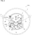
- FIGs. 2 and 3 are each a lateral cross-sectional view of a main configuration of the laser oscillation device 1.
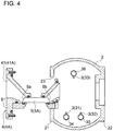
- FIG. 4 is a view of the laser oscillation device 1 shown in FIG. 2 , where a cartridge 4 is removed from a refrigerant container 2.
- FIGs. 5 and 6 are diagrams showing a laser gain medium 5 according to an embodiment in detail.
- FIG. 5 is a diagram of a laser gain medium 5A into which laser seed light LM enters in a direction perpendicular to the incidence medium surface.
- FIG. 6 is a diagram of a laser gain medium 5B into which the laser seed light LM enters along a longitudinal direction.
- the laser oscillation device 1 includes a refrigerant container 2, at least one cartridge 4, at least one nozzle 3 (see FIG. 2 ), and a vacuum heat insulating container 7.
- the refrigerant container 2 is an airtight container that seals the inside from the outside.
- the refrigerant container 2 is a cylindrical container having an annular lateral cross section, including a front plate portion 21 and a rear plate portion 22 disposed on the side surface of the refrigerant container 2.
- the cartridge 4 has a cuboid shape, and the incidence path section 41 is disposed on an end of the cartridge 4. Accordingly, an incidence medium surface 5a of the laser gain medium 5 is visible via the incidence path section 41. Further, although not shown, an optical fiber for measuring the temperature of the laser gain medium 5 is attached. The optical fiber is removed out of the refrigerant container 2 via a feedthrough (not shown) disposed on a flange 61 described below.
- the laser gain medium 5 is for amplifying laser seed light.
- a state of population inversion in which stimulated emission dominates absorption is achieved through pumping, and laser seed light is amplified by stimulated emission.
- the laser gain medium 5 has a trapezoid shape in which the laser seed light LM is reflected for an odd number of times in the embodiment shown in FIGs. 2 and 3
- the shape is not limited to this, and may be a parallelogram in which the laser seed light LM is reflected for an even number of times.
- the number of reflection is determined in a range in which excitation light LE reaches without attenuating inside the medium, which is normally about three times.
- the incidence path section 41 is disposed in a front region of the incidence medium surface 5a of the laser gain medium 5.
- the cartridge 4 is disposed so as to be insertable and removable with respect to the refrigerant container 2 along the longitudinal direction of the laser gain medium 5.
- the at least one nozzle 3 is for spraying a refrigerant R to the laser gain medium 5, and is disposed inside the refrigerant container 2.
- two nozzles 31, 32 are disposed in a region facing the first surface of the laser gain medium 5, and one nozzle 33 is disposed in a region facing the second surface of the laser gain medium 5.
- Refrigerant pipes 34, 35, 36 for supplying the refrigerant R are connected respectively to the nozzles 31, 32, 33.
- the refrigerant R is supplied to the respective nozzles 31, 32, 33 from a refrigerant supply source (not shown), and is sprayed to the laser gain medium 5 through the nozzles 31, 32, 33.
- the sprayed refrigerant R is recovered through a recovery pipe 37 connected to a bottom section of the refrigerant container 2.
- the vacuum heat insulating container 7 forms a vacuum heat insulating layer V on the outer peripheral side of the refrigerant container 2, and houses the refrigerant container 2 inside.
- the vacuum heat insulating container 7 is a cylindrical airtight container having an annular lateral cross section, similarly to the refrigerant container 2. Further, as described above, since the vacuum heat insulating layer V is formed in the vacuum heat insulating container 7, the refrigerant container 2 and the cartridge 4 housed in the vacuum heat insulating container 7 are sealed by seal members such as an O-ring and an indium seal. Further, although not shown, the vacuum heat insulating container 7 is equipped with an outlet, a valve, a vacuum gauge, legs, etc.
- the vacuum heat insulating container 7 includes an incidence window 71.
- the incidence window 71 for taking the laser seed light LM traveling toward the incidence path section 41 into the vacuum heat insulating container.
- the incidence window 71 is disposed at the same height-directional position as the height-directional position of the laser gain medium 5.
- the incidence path section 41B is configured to guide the laser seed light LM to the laser gain medium 5B along the longitudinal direction of the laser gain medium 5B.
- the laser gain medium 5B is formed so that the laser seed light LM entering along the longitudinal direction is totally reflected. That is, the laser gain medium 5B is formed so that the angle ⁇ is greater than the critical angle ( ⁇ >critical angle).
- the angle ⁇ of the incidence medium surface 5a is 32.34 degrees, provided that the refractive index n1 of air is 1.00, the refractive index n2 of the laser gain medium 5B is 1.82, the refractive index n3 of the refrigerant is 1.20, and the angle ⁇ is 60 degrees.
- the incidence path section 41B is configured to guide the laser seed light LM to the laser gain medium 5 along the longitudinal direction of the laser gain medium 5B, and thereby it is possible to reduce a cross section of the incidence path section 41 that is orthogonal to the longitudinal direction of the laser gain medium 5B. Accordingly, it is possible to reduce the size of the cartridge 4. Furthermore, the axis of light is straight in front and rear of the laser gain medium 5B, and thus mirrors or the like can be disposed in a straight line.
- the incidence path section 41A is configured to guide the laser seed light LM to the laser gain medium 5A so that the laser seed light LM enters in a direction perpendicular to the incidence medium surface 5a of the laser gain medium 5.
- the laser gain medium 5A is formed so that the laser seed light LM entering in a direction perpendicular to the incidence medium surface 5a is totally reflected. That is, the laser gain medium 5A is formed so that the angle ⁇ is greater than the critical angle ( ⁇ >critical angle).
- the incidence path section 41 is configured to guide the laser seed light LM to the laser gain medium 5 so that the laser seed light LM enters in a direction perpendicular to the incidence medium surface 5a of the laser gain medium 5A, and thereby it is possible to suppress reflection when the laser seed light LM enters the laser gain medium 5A.
- the laser gain medium 5 has a corner cube 51 having at least two faces that form a right angle, at an end portion opposite to the incidence path section 41. Furthermore, the incidence path section 41 is configured to guide laser light LB reflected by the corner cube 51 and emitted from the laser gain medium 5 outside the vacuum heat insulating container.
- the incidence medium surface 5a of the laser gain medium 5 is coated with an anti-reflection layer, and reflection of the laser seed light LM is suppressed. Furthermore, the two faces forming the corner cube 51 of the laser gain medium 5 are coated with total reflection mirrors, and reflection of the laser seed light LM is promoted.
- the laser gain medium 5C includes a corner cube 5C1 formed by two faces that form a right angle at an end portion opposite to the incidence medium surface 5Ca.
- the corner cube 5C1 is for retro-reflecting incident light.
- a rear end surface 5Cb and a side surface 5Cc adjacent to the rear end surface 5Cb form a right angle.
- the laser gain medium 5D includes a corner cube 5D1 formed by two faces that form a right angle at an end portion opposite to the incidence medium surface 5Da.
- the corner cube 5D1 is for retro-reflecting incident light.
- two rear end surfaces 5Db that are adjacent to each other form a right angle.
- the incidence path section 41 is configured to guide the laser light LB reflected by the corner cube 51 and emitted from the laser gain medium 5 outside the vacuum heat insulating container 7, and thereby it is possible to guide the laser light LB reflected by the corner cube 51 and emitted from the laser gain medium 5 outside the vacuum heat insulating container 7.
- the laser oscillation device 1 is configured to guide the laser light LB reflected by the corner cube 51 opposite to the incidence medium surface 5a and emitted from the laser gain medium 5 outside the vacuum heat insulating container.
- the laser oscillation device 1 includes a seed-light incidence system 11, an excitation-light incidence system 12, and a laser-light emission system 13.
- the seed-light incidence system 11 includes a seed light source 111, a mirror 112, a light polarizer 113, a quarter waveplate 114, and a mirror 115.
- the seed light source 111 comprises a solid laser or a fiber laser, for instance.
- the quarter waveplate 114 is for preventing laser light (amplified light) from returning to the seed light source from the laser gain medium 5.
- the quarter waveplate 115 turns the outgoing polarization direction, so that the inverse light does not pass through the light polarizer 113.
- the excitation-light incidence system 12 is for incidence (supply) of the excitation light LE to the laser gain medium 5.
- the excitation-light incidence system 12 includes an excitation light source 121 and a focusing lens group 122.
- the excitation light source 121 comprises an excitation laser, for instance, a semiconductor laser.
- the focusing lens group 122 is for focusing excitation light LE toward a region of reflection of the laser seed light LM.
- the focusing lens group 122 is not limited to lens and may comprise mirrors.
- the laser-light emission system 13 is for emission (output) of the amplified laser light LB.
- the laser-light emission system 13 is configured to pass through a different path from the laser seed light LM and the excitation light LE, and comprises a mirror 131, for instance.
- the range in which the excitation light LE reaches without attenuating inside the laser gain medium 5 is the same as the laser oscillation device 1 that outputs from an output surface opposite to the incidence medium surface 5a, the reflection number is doubled in a laser oscillation device provided with the laser gain medium 5 of the same size, which improves the efficiency.
- FIGs. 11 and 12 are each a vertical cross-sectional view of the cartridge 4 according to an embodiment.
- the cartridge 4 shown in FIG. 11 is attached to the laser oscillation device 1A shown in FIG 2 so as to be insertable and removable.
- the cartridge 4 shown in FIG. 12 is attached to the laser oscillation device 1B shown in FIG. 3 so as to be insertable and removable.
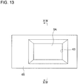
- FIG. 13 is a view of the cartridge 4A shown in FIG. 11 , as seen in the direction of arrows XIII
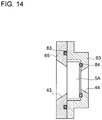
- FIG. 14 is a view of the cartridge shown in FIG. 12 , as seen in the direction of arrows XIV.
- FIG. 15 is a schematic perspective diagram of an external view of the cartridge 4B shown in FIG. 12 .
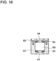
- FIG. 16 is a cross-sectional view of the cartridge 4B shown in FIG. 15 , as seen in the direction of arrows XVI, and
- FIG. 17 is a back-side view of the cartridge 4B shown in FIG 15 .
- the cartridge 4 further includes an output path section 42 disposed on an opposite side of the laser gain medium 5 from the incidence path section 41, for guiding the laser light LB outputted from the laser gain medium 5.
- the output path section 42A is configured such that the laser light LB is outputted in a direction perpendicular to the output surface 5b of the laser gain medium 5A (see FIG. 2 ).
- the output path section 42B is configured such that the laser light LB is outputted along the longitudinal direction of the laser gain medium 5A (see FIG. 3 ).
- the cartridge 4 further includes the output path section 42 for guiding the laser light LB emitted from the laser gain medium 5, and thereby it is possible to guide the laser light LB emitted from the laser gain medium 5 through the output path section 42.
- the cartridge 4 has openings 43, 44 in a region facing the nozzle 3, so that a jet stream of the refrigerant R from the nozzle 3 hits the laser gain medium 5.
- the opening 43 is disposed in a region facing the nozzles 31, 32 (see FIG. 2 ), so that jet flows of the refrigerant R from the nozzles 31, 32 hit the first surface of the laser gain medium 5A.
- the opening 44 is disposed in a region facing the nozzle 33 (see FIG. 2 ), so that a jet flow of the refrigerant R from the nozzle 33 hits the second surface of the laser gain medium 5A.
- the opening 43 is disposed in a region facing the nozzles 31, 32 (see FIG. 3 ), so that jet flows of the refrigerant R from the nozzles 31, 32 hit the first surface of the laser gain medium 5B.
- the opening 44 is disposed in a region facing the nozzle 33 (see FIG. 3 ), so that a jet flow of the refrigerant R from the nozzle 33 hits the second surface of the laser gain medium 5B.
- the cartridge 4 has the openings 43, 44 in a region facing the nozzle 3, so that a jet flow of the refrigerant R from the nozzle 3 hits the laser gain medium 5, and thereby a jet flow of the refrigerant R from the nozzle 3 passes through the openings 43, 44 in a region facing the nozzle 3 and hits the laser gain medium 5.
- the cartridge 4 has a flange 61 on the first end side in the longitudinal direction, the flange 61 forming the incidence path section 41. Furthermore, the refrigerant container 2 has a container opening 32 (front opening) which is smaller than the contour of the flange 61 and through which the second end side of the cartridge 4 can pass through. The flange 61 of the cartridge 4 is fixed to the front plate portion 21 forming a wall member of the refrigerant container 2 around the container opening 23.
- an O-ring 81 is disposed between the flange 61 of the cartridge 4 and the front plate portion 21 of the refrigerant container 2, thus sealing the gap between the flange 61 of the cartridge 4 and the front plate portion 21 of the refrigerant container 2.
- a bottomed threaded hole is disposed on the front plate portion of the refrigerant container 2, in a position corresponding to the through hole. Accordingly, the refrigerant R is prevented from leaking through the threaded hole.
- the second end side of the cartridge 4 is inserted into the container opening 23 of the refrigerant container 2, and the flange 61 of the cartridge 4 is fixed to the front plate portion 21 of the wall member around the container opening 23.
- the flange 61 of the cartridge 4 is fixed to the front plate portion 21 of the wall member around the container opening 23.
- a second end portion 62 of the cartridge 4 is in contact with a rear plate portion 22 forming an inner wall surface of the refrigerant container 2, in a region of the refrigerant container 2 that intersects with a virtual line M extended from the container opening 23 in the longitudinal direction.
- the cartridge 4A has an inlet 621 on the second side in the longitudinal direction, while the refrigerant container 2 has a container opening 24A (rear opening) which is greater than the contour of the inlet 621 and through which the cartridge 4A cannot pass through. Further, the inlet 621 of the cartridge 4A is fitted into the container opening 24A, thus being fixed to the rear plate portion 22 forming a wall member of the refrigerant container 2 around the container opening 24A.
- an O-ring 82 is disposed between the second end portion 62 of the cartridge 4A and the rear plate portion 22 forming the inner wall surface of the refrigerant container 2, thus sealing the gap between the second end portion 62 of the cartridge 4 and the rear plate portion 22 of the refrigerant container 2.
- the cartridge 4B has a position-determining portion 622 on the second side in the longitudinal direction, while the refrigerant container 2 has a container opening 24B (rear opening) in which the position-determining portion 622 fits in, and through which the cartridge 4B cannot pass through. Further, the position-determining portion 622 of the cartridge 4B is fitted into the container opening 24B, thus being fixed to the rear plate portion 22 forming a wall member of the refrigerant container 2 around the container opening 24B.
- the second end portion 62 of the cartridge 4 is in contact with the inner wall surface of the refrigerant container 2 in a region of the refrigerant container 2 that intersects with the virtual line M extended from the container opening 23 in the longitudinal direction, and thereby the second end portion 62 of the cartridge 4 is also supported on the inner wall surface of the refrigerant container 2.
- the cartridge 4 includes the laser gain medium 5 and a holder portion 63 for holding the laser gain medium 5, the holder portion 63 forming the incidence path section 41.
- the laser gain medium 5 is disposed so as to be insertable and removable with respect to the holder portion 63 in a direction orthogonal to the longitudinal direction.
- an O-ring 83 is disposed between the holder portion 63 and the laser gain medium 5, thus sealing the gap between the holder portion 63 and the laser gain medium 5.
- the laser gain medium 5 is disposed so as to be insertable and removable with respect to the holder portion 63 along a direction orthogonal to the longitudinal direction, and thereby it is possible to replace the laser gain medium 5 easily with respect to the holder portion 63.
- the holder portion 63 includes a holder body 64 having a holder opening 641 through which the laser gain medium 5 can pass through in a direction orthogonal to the longitudinal direction, and a lid member 65 configured to fix the laser gain medium 5 having passed through the holder opening 641 along with the holder body 64.
- an O-ring 84 is disposed between the laser gain medium 5 and the lid member 65, thus sealing the gap between the laser gain medium 5 and the lid member 65.
- the holder portion 63 includes a holder body 64 having a holder opening 641 through which the laser gain medium 5 can pass through in a direction orthogonal to the longitudinal direction, and a lid member 65 configured to fix the laser gain medium 5 having passed through the holder opening 641 with the holder body 64, and thereby the lid member 65 can fix the laser gain medium 5 having passed through the holder opening 641 of the holder body 64 along with the holder body 64.
- the refrigerant R is liquid nitrogen, and thus the laser gain medium 5 sprayed with the refrigerant R can be cooled to a temperature not more than 100K.
- the laser gain medium 5 includes an optical medium 52 transparent to the laser seed light LM and having the first surface 52a and the second surface 52b facing the first surface 52a, and gain medium sheets 53, 54 attached respectively to the first surface 52a and the second surface 52b of the optical medium 52 for amplifying the laser seed light LM.
- the nozzle 3 is configured to spray the refrigerant R to the gain medium sheets 53, 54.
- the refrigerant R is sprayed to the gain medium sheets 53, 54 to cool the gain medium sheets 53, 54, and thereby it is possible to cool the laser gain medium 5 efficiently.
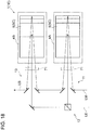
- FIG. 18 is a conceptual configuration diagram of a laser oscillation device 1 (1E) according to an embodiment.
- a plurality of cartridges 4 including the first cartridge 4C and the second cartridge 4D are disposed so as to be insertable and removable in the longitudinal direction with respect to the refrigerant container 2.
- the plurality of cartridges 4 including the first cartridge 4C and the second cartridge 4D are disposed so as to be insertable and removable in the longitudinal direction with respect to the refrigerant container 2, and thereby it is possible to replace the plurality of cartridges 4 including the first cartridge 4C and the second cartridge 4D easily with respect to the refrigerant container 2.
- the laser seed light LM is configured to pass through the laser gain medium 5B of the first cartridge 4C to be amplified, and then pass through the laser gain medium 5B of the second cartridge 4D to be further amplified.
- the laser seed light LM is configured to pass through the laser gain medium 5 of the first cartridge 4C to be amplified, and then pass through the laser gain medium 5 of the second cartridge 4D to be further amplified.
- the laser seed light LM passes through the laser gain medium 5 of the first cartridge 4C to be amplified, and then passes through the laser gain medium 5 of the second cartridge 4D to be further amplified
- FIG. 19 is a conceptual configuration diagram of a laser oscillation device 1 (1F) according to an embodiment.
- the cartridge 4 is disposed so as to be insertable and removable with respect to the vacuum heat insulating container 7 along the longitudinal direction of the laser gain medium 5.
- the cartridge 4F includes a flange 66, a lid member 67, a coupling member 68, and a frame member 69.
- the flange 66 is a portion to be in close contact with the refrigerant container 2, and corresponds to the above described flange 61.
- An O-ring 85 is disposed between the flange 66 and the refrigerant container 2, thus sealing the gap between the refrigerant container 2 and the flange 66 when the cartridge 4F is mounted to the vacuum heat insulating container 7.
- the lid member 67 is a portion to be in close contact with the vacuum heat insulating container 7, and corresponds to the above described incidence window 71.
- An O-ring 86 is disposed between the lid member 67 and the vacuum heat insulating container 7, thus sealing the gap between the vacuum heat insulating container 7 and the lid member 67 when the cartridge 4F is mounted to the vacuum heat insulating container 7.
- the coupling member 68 is for coupling the flange 66 and the lid member 67.
- the coupling member 68 comprises a cylindrically-shaped tube member, and has a hole 681 communicating with the inside of the vacuum heat insulating container disposed on the side surface of the tube member.
- the frame member 69 is for mounting glass 711 to the incidence window 671 disposed on the lid member 67, and has an annular shape. Furthermore, an O-ring 87 is disposed between the glass 711 and the lid member 67, thus sealing the gap between the glass 711 and the lid member 67.
- the cartridge 4 is disposed so as to be insertable and removable with respect to the vacuum heat insulating container 7 along the longitudinal direction of the laser gain medium 5, and thereby it is possible to replace the laser gain medium 5 merely by removing the cartridge 4 from the vacuum heat insulating container 7.
- the cartridge 4 is disposed so as to be insertable and removable with respect to the vacuum heat insulating container 7 along the longitudinal direction of the laser gain medium 5 in the above configuration, the cartridge 4 is also disposed so as to be insertable and removable with respect to the refrigerant container 2 along the longitudinal direction of the laser gain medium 5, and is attached to the refrigerant container 2.
Landscapes
- Physics & Mathematics (AREA)
- Electromagnetism (AREA)
- Engineering & Computer Science (AREA)
- Plasma & Fusion (AREA)
- Optics & Photonics (AREA)
- Chemical & Material Sciences (AREA)
- Crystallography & Structural Chemistry (AREA)
- Lasers (AREA)
Abstract
Description
- The present disclosure relates to a laser oscillation device.
- A solid laser oscillation device, typically a YAG laser using yttrium (Y) aluminum (Al) garnet (G) crystals as a laser gain medium, is required to cool the laser gain medium to keep the lower energy level less populated, in order to improve the efficiency of laser oscillation.
- For instance, a YAG laser doped with ytterbium (Yb) is required to cool the laser gain medium to a temperature not more than 120K, or more preferably, not more than 100K.
-
Patent Document 1 discloses a laser oscillator. The laser oscillator includes an optical medium, a plurality of first-surface side gain media, at least one second-surface side gain medium, and a cooling unit. The optical medium is transparent to laser light, and includes an incidence medium surface, the first surface, and the second surface facing the first surface. The plurality of first-surface side gain media are excited by excitation light, and amplify laser light while totally reflecting the laser light. The first-surface side media are joined to the optical medium on the first surface of the optical medium. The at least one second-surface side gain medium is, similarly to the first-surface side gain media, excited by excitation light, and amplify laser light while totally reflecting the laser light. The second-surface side medium is joined to the optical medium on the second surface of the optical medium. The cooling unit cools the back surface side of each of the plurality of first-surface side gain media and the at least one second-surface side gain medium, and is disposed so as to cool a plurality of first reflection surfaces and at least one second reflection surface of the gain media. - Patent Document 1:
JP2010-114162A - Meanwhile, although laser gain media are expendables because of their fragility against thermal stress and the like, the laser gain media are surrounded by mirrors and the like that cannot be easily adjusted, which makes it difficult to replace the laser gain media.
- In view of the above, an object of at least one embodiment of the present invention is to provide a laser oscillation device equipped with an easily replaceable laser gain medium.
-
- (1) A laser oscillation device according to at least one embodiment of the present invention comprises: a refrigerant container; at least one cartridge which is attached to the refrigerant container and which includes a laser gain medium and an incidence path section for guiding laser seed light to the laser gain medium; at least one nozzle for spraying a refrigerant to the laser gain medium, the at least one nozzle being disposed inside the refrigerant container; and a vacuum heat insulating container housing the refrigerant container inside and forming a vacuum insulation layer on an outer peripheral side of the refrigerant container. The cartridge is disposed so as to be insertable and removable with respect to the refrigerant container along a longitudinal direction of the laser gain medium.
With the above configuration (1), the at least one cartridge is disposed so as to be insertable and removable with respect to the refrigerant container along the longitudinal direction of the laser gain medium, and thereby it is possible to replace the laser gain medium in the cartridge easily with respect to the refrigerant container. - (2) In some embodiments, in the above configuration (1), the vacuum heat insulating container includes an incidence window for introducing the laser seed light traveling toward the incidence path section into the vacuum heat insulating container.
With the above configuration (2), the vacuum heat insulating container includes the incidence window for taking the laser seed light traveling toward the incidence path section into the vacuum heat insulating container, and thereby it is possible to take the laser seed light traveling toward the incidence path section into the vacuum heat insulating container through the incidence window. - (3) In some embodiments, in the above configuration (1) or (2), the incidence path section is configured to guide the laser seed light to the laser gain medium along the longitudinal direction of the laser gain medium.
With the above configuration (3), the incidence path section is configured to guide the laser seed light to the laser gain medium along the longitudinal direction of the laser gain medium, and thereby it is possible to reduce a cross section of the incidence path section that is orthogonal to the longitudinal direction of the laser gain medium. Accordingly, it is possible to reduce the size of the cartridge. - (4) In some embodiments, in the above configuration (1) or (2), the incidence path section is configured to guide the laser seed light to the laser gain medium so that the laser seed light enters in a direction perpendicular to an incidence medium surface of the laser gain medium.
With the above configuration (4), the incidence path section is configured to guide the laser seed light to the laser gain medium so that the laser seed light enters in a direction perpendicular to the incidence medium surface of the laser gain medium, and thereby it is possible to suppress reflection when the laser seed light enters the laser gain medium. - (5) In some embodiments, in any one of the above configurations (1) to (4), the laser gain medium has a corner cube including at least two faces forming a right angle at an end portion opposite to the incidence path section. The incidence path section is configured to guide laser light reflected by the corner cube and outputted from the laser gain medium outside the vacuum heat insulating container.
With the above configuration (5), the incidence path section is configured to guide the laser light reflected by the corner cube and emitted from the laser gain medium outside the vacuum heat insulating container, and thereby it is possible to guide the laser light reflected by the corner cube and emitted from the laser gain medium outside the vacuum heat insulating container. - (6) In some embodiments, in any one of the above configurations (1) to (4), the cartridge further includes an output path section for guiding laser light outputted from the laser gain medium, the output path section being disposed on an opposite side of the laser gain medium from the incidence path section.
With the above configuration (6), the cartridge further includes the output path section for guiding the laser light outputted from the laser gain medium, and thereby it is possible to guide the laser light outputted from the laser gain medium through the output path section. - (7) In some embodiments, in any one of the above configurations (1) to (6), the cartridge has an opening in a region facing the nozzle so that a jet flow of the refrigerant from the nozzle collides with the laser gain medium.
With the above configuration (7), the cartridge has the opening in a region facing the nozzle, so that a jet flow of the refrigerant from the nozzle hits the laser gain medium, and thereby a jet flow of the refrigerant from the nozzle passes through the openings in a region facing the nozzle and hits the laser gain medium. - (8) In some embodiments, in any one of the above configurations (1) to (7), the cartridge has a flange on a first end side in the longitudinal direction, the flange forming the incidence path section. The refrigerant container has a container opening which is smaller than a contour of the flange and through which a second end side of the cartridge is passable. The flange of the cartridge is fixed to a wall member of the refrigerant container around the container opening.
With the above configuration (8), the second end side of the cartridge is inserted into the container opening of the refrigerant container, and the flange of the cartridge is fixed to a wall member around the container opening. Thus, it is possible to replace the laser gain medium in the cartridge easily with respect to the refrigerant container. - (9) In some embodiments, in the above configuration (8), a second end portion of the cartridge is in contact with an inner wall surface of the refrigerant container in a region of the refrigerant container intersecting with a virtual line extended in the longitudinal direction from the container opening.
With the above configuration (9), the second end portion of the cartridge is in contact with the inner wall surface of the refrigerant container in a region of the refrigerant container that intersects with a virtual line extended from the container opening in the longitudinal direction, and thereby the second end portion of the cartridge is also supported on the inner wall surface of the refrigerant container. - (10) In some embodiments, in any one of the above configurations (1) to (9), the cartridge includes: the laser gain medium; and a holder portion for holding the laser gain medium, the holder portion forming the incidence path section. The laser gain medium is disposed so as to be insertable and removable with respect to the holder portion along a direction orthogonal to the longitudinal direction.
With the above configuration (10), the laser gain medium is disposed so as to be insertable and removable with respect to the holder portion along a direction orthogonal to the longitudinal direction, and thereby it is possible to replace the laser gain medium easily with respect to the holder portion. - (11) In some embodiments, in the above configuration (10), the holder portion includes: a holder body having a holder opening through which the laser gain medium is passable in a direction orthogonal to the longitudinal direction; and a lid member configured to fix the laser gain medium having passed through the holder opening along with the holder body.
With the above configuration (11), the holder portion includes a holder body having a holder opening through which the laser gain medium can pass through in a direction orthogonal to the longitudinal direction, and a lid member configured to fix the laser gain medium having passed through the holder opening with the holder portion, and thereby the lid member can fix the laser gain medium having passed through the holder opening of the holder body along with the holder body. - (12) In some embodiments, in any one of the above configurations (1) to (11), the refrigerant comprises liquid nitrogen.
With the above configuration (12), the refrigerant is liquid nitrogen, and thus the laser gain medium sprayed with the refrigerant can be cooled to a temperature not more than 100K. - (13) In some embodiments, in any one of the above configurations (1) to (12), the laser gain medium includes: an optical medium which is transparent to the laser seed light and which has a first surface and a second surface facing the first surface; and a gain medium sheet for amplifying the laser seed light, the gain medium sheet being attached to each of the first surface and the second surface of the optical medium. The nozzle is configured to spray the refrigerant onto the gain medium sheet.
With the above configuration (13), the refrigerant is sprayed to the gain medium sheet to cool the gain medium sheet, and thereby it is possible to cool the laser gain medium efficiently. - (14) In some embodiments, in any one of the above configurations (1) to (13), the cartridge comprises a plurality of cartridges including a first cartridge and a second cartridge which are insertable and removable with respect to the refrigerant container along the longitudinal direction.
With the above configuration (14), the plurality of cartridges including the first cartridge and the second cartridge are disposed so as to be insertable and removable in the longitudinal direction with respect to the refrigerant container, and thereby it is possible to replace the plurality of cartridges including the first cartridge and the second cartridge easily with respect to the refrigerant container. - (15) In some embodiments, in the above configuration (14), the laser oscillation device is configured such that the laser seed light passes through the laser gain medium of the first cartridge to be amplified and then passes through the laser gain medium of the second cartridge to be further amplified.
With the above configuration (15), the laser oscillation device is configured such that the laser seed light passes through the laser gain medium of the first cartridge to be amplified, and then passes through the laser gain medium of the second cartridge to be further amplified. Thus, the laser seed light passes through the laser gain medium of the first cartridge to be amplified, and then passes through the laser gain medium of the second cartridge to be further amplified. - According to at least one embodiment of the present invention, it is possible to replace the laser gain medium in the cartridge easily with respect to the refrigerant container.
-
-
FIG. 1 is a schematic perspective diagram of an external view of a main part of a laser oscillation device according to an embodiment of the present invention. -
FIG. 2 is a lateral cross-sectional view of a main configuration of a laser oscillation device according to an embodiment of the present invention. -
FIG. 3 is a lateral cross-sectional view of a main configuration of a laser oscillation device according to an embodiment of the present invention. -
FIG. 4 is a view of the laser oscillation device shown inFIG. 2 , where a cartridge is removed from a refrigerant container. -
FIG. 5 is a detailed view of a laser gain medium according to an embodiment. -
FIG. 6 is a detailed view of a laser gain medium according to an embodiment. -
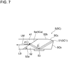
FIG. 7 is a detailed view of a laser gain medium according to an embodiment. -
FIG 8 is a detailed view of a laser gain medium according to an embodiment. -
FIG. 9 is a conceptual configuration diagram of a laser oscillation device provided with the laser gain medium shown inFIG. 7 . -
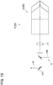
FIG 10 is a conceptual configuration diagram of a laser oscillation device provided with the laser gain medium shown inFIG. 8 . -
FIG. 11 is a vertical cross-sectional view of a cartridge according to an embodiment. -
FIG. 12 is a vertical cross-sectional view of a cartridge according to an embodiment. -
FIG 13 is a view of the cartridge shown inFIG 11 , as seen in the direction of arrows XIII. -
FIG. 14 is a view of the cartridge shown inFIG. 12 , as seen in the direction of arrows XIV. -
FIG 15 is a schematic perspective view of an external view of the cartridge shown inFIG. 12 . -
FIG 16 is a view of the cartridge shown inFIG. 15 , as seen in the direction of arrows XVI. -
FIG. 17 is a back-side view of the cartridge shown inFIG. 15 . -
FIG. 18 is a conceptual configuration diagram of a laser oscillation device according to an embodiment of the present invention. -
FIG 19 is a conceptual configuration diagram of a laser oscillation device according to an embodiment of the present invention. - Embodiments of the present invention will now be described in detail with reference to the accompanying drawings. It is intended, however, that unless particularly specified, dimensions, materials, shapes, relative positions and the like of components described in the embodiments shall be interpreted as illustrative only and not intended to limit the scope of the present invention.
- For instance, an expression of relative or absolute arrangement such as "in a direction", "along a direction", "parallel", "orthogonal", "centered", "concentric" and "coaxial" shall not be construed as indicating only the arrangement in a strict literal sense, but also includes a state where the arrangement is relatively displaced by a tolerance, or by an angle or a distance whereby it is possible to achieve the same function.
- Further, for instance, an expression of a shape such as a rectangular shape or a cylindrical shape shall not be construed as only the geometrically strict shape, but also includes a shape with unevenness or chamfered corners within the range in which the same effect can be achieved.
- On the other hand, an expression such as "comprise", "include", "have", "contain" and "constitute" are not intended to be exclusive of other components.
-
FIG. 1 is a schematic perspective diagram of an external view of a main part of alaser oscillation device 1 according to an embodiment of the present invention.FIGs. 2 and3 are each a lateral cross-sectional view of a main configuration of thelaser oscillation device 1.FIG. 4 is a view of thelaser oscillation device 1 shown inFIG. 2 , where acartridge 4 is removed from arefrigerant container 2. - Further,
FIGs. 5 and6 are diagrams showing alaser gain medium 5 according to an embodiment in detail.FIG. 5 is a diagram of alaser gain medium 5A into which laser seed light LM enters in a direction perpendicular to the incidence medium surface.FIG. 6 is a diagram of alaser gain medium 5B into which the laser seed light LM enters along a longitudinal direction. - As shown in
FIG. 1 , thelaser oscillation device 1 according to at least one embodiment of the present invention includes arefrigerant container 2, at least onecartridge 4, at least one nozzle 3 (seeFIG. 2 ), and a vacuumheat insulating container 7. - The
refrigerant container 2 is an airtight container that seals the inside from the outside. - In an embodiment shown in
FIGs. 1 to 3 , therefrigerant container 2 is a cylindrical container having an annular lateral cross section, including afront plate portion 21 and arear plate portion 22 disposed on the side surface of therefrigerant container 2. - As shown in
FIGs. 2 and3 , the at least onecartridge 4 is attached to therefrigerant container 2. Thecartridge 4 includes thelaser gain medium 5 and anincidence path section 41. - In an embodiment shown in
FIGs. 2 and3 , thecartridge 4 has a cuboid shape, and theincidence path section 41 is disposed on an end of thecartridge 4. Accordingly, an incidencemedium surface 5a of thelaser gain medium 5 is visible via theincidence path section 41. Further, although not shown, an optical fiber for measuring the temperature of thelaser gain medium 5 is attached. The optical fiber is removed out of therefrigerant container 2 via a feedthrough (not shown) disposed on aflange 61 described below. - The
laser gain medium 5 is for amplifying laser seed light. A state of population inversion in which stimulated emission dominates absorption is achieved through pumping, and laser seed light is amplified by stimulated emission. - In the embodiment shown in
FIGs. 2 and3 , thelaser gain medium 5 is a YAG laser using yttrium (Y) aluminum (Al) garnet (G) crystals, doped with ytterbium (Yb). Accordingly, thelaser gain medium 5 is required to be cooled to a temperature not more than 120K, or more preferably, not more than 100K. - Furthermore, while the
laser gain medium 5 has a trapezoid shape in which the laser seed light LM is reflected for an odd number of times in the embodiment shown inFIGs. 2 and3 , the shape is not limited to this, and may be a parallelogram in which the laser seed light LM is reflected for an even number of times. The number of reflection is determined in a range in which excitation light LE reaches without attenuating inside the medium, which is normally about three times. - The
incidence path section 41 is for guiding the laser seed light LM to thelaser gain medium 5. - In the embodiment shown in
FIGs. 2 and3 , theincidence path section 41 is disposed in a front region of the incidencemedium surface 5a of thelaser gain medium 5. - As shown in
FIGs. 2 and4 , thecartridge 4 is disposed so as to be insertable and removable with respect to therefrigerant container 2 along the longitudinal direction of thelaser gain medium 5. - As shown in
FIGs. 2 and3 , the at least onenozzle 3 is for spraying a refrigerant R to thelaser gain medium 5, and is disposed inside therefrigerant container 2. - In the embodiment shown in
FIGs. 2 and3 , twonozzles laser gain medium 5, and onenozzle 33 is disposed in a region facing the second surface of thelaser gain medium 5.Refrigerant pipes nozzles respective nozzles laser gain medium 5 through thenozzles FIG. 1 , the sprayed refrigerant R is recovered through arecovery pipe 37 connected to a bottom section of therefrigerant container 2. - As shown in
FIGs. 2 and3 , the vacuumheat insulating container 7 forms a vacuum heat insulating layer V on the outer peripheral side of therefrigerant container 2, and houses therefrigerant container 2 inside. - In the embodiment shown in
FIGs. 2 and3 , the vacuumheat insulating container 7 is a cylindrical airtight container having an annular lateral cross section, similarly to therefrigerant container 2. Further, as described above, since the vacuum heat insulating layer V is formed in the vacuumheat insulating container 7, therefrigerant container 2 and thecartridge 4 housed in the vacuumheat insulating container 7 are sealed by seal members such as an O-ring and an indium seal. Further, although not shown, the vacuumheat insulating container 7 is equipped with an outlet, a valve, a vacuum gauge, legs, etc. - With the above configuration, the at least one
cartridge 4 is disposed so as to be insertable and removable with respect to therefrigerant container 2 along the longitudinal direction of thelaser gain medium 5, and thereby it is possible to replace thelaser gain medium 5 in thecartridge 4 easily with respect to therefrigerant container 2. - As shown in
FIGs. 1 to 3 , in some embodiments, the vacuumheat insulating container 7 includes anincidence window 71. Theincidence window 71 for taking the laser seed light LM traveling toward theincidence path section 41 into the vacuum heat insulating container. - In the embodiment shown in
FIGs. 1 and3 , theincidence window 71 is disposed at the same height-directional position as the height-directional position of thelaser gain medium 5. - With the above configuration, the vacuum
heat insulating container 7 includes theincidence window 71 for taking the laser seed light LM traveling toward theincidence path section 41 into the vacuum heat insulating container, and thereby it is possible to take the laser seed light LM traveling toward theincidence path section 41 into the vacuumheat insulating container 7 through theincidence window 71. Theincidence window 71 is coated with an anti-reflection layer (not shown), and reflection of the laser seed light LM is suppressed. - As shown in
FIG. 3 , in some embodiments, theincidence path section 41B is configured to guide the laser seed light LM to thelaser gain medium 5B along the longitudinal direction of thelaser gain medium 5B. - As shown in
FIG. 6 , thelaser gain medium 5B according to some embodiments is formed so that the laser seed light LM entering along the longitudinal direction is totally reflected. That is, thelaser gain medium 5B is formed so that the angle β is greater than the critical angle (β>critical angle). - In the embodiment shown in
FIG. 6 , the angle α of the incidencemedium surface 5a is 32.34 degrees, provided that the refractive index n1 of air is 1.00, the refractive index n2 of thelaser gain medium 5B is 1.82, the refractive index n3 of the refrigerant is 1.20, and the angle β is 60 degrees. - Furthermore, the incidence
medium surface 5a of thelaser gain medium 5B is coated with an anti-reflection layer (not shown), and reflection of the laser seed light LM is suppressed. - With the above configuration, the
incidence path section 41B is configured to guide the laser seed light LM to thelaser gain medium 5 along the longitudinal direction of thelaser gain medium 5B, and thereby it is possible to reduce a cross section of theincidence path section 41 that is orthogonal to the longitudinal direction of thelaser gain medium 5B. Accordingly, it is possible to reduce the size of thecartridge 4. Furthermore, the axis of light is straight in front and rear of thelaser gain medium 5B, and thus mirrors or the like can be disposed in a straight line. - As shown in
FIG. 2 , in some embodiments, theincidence path section 41A is configured to guide the laser seed light LM to thelaser gain medium 5A so that the laser seed light LM enters in a direction perpendicular to the incidencemedium surface 5a of thelaser gain medium 5. - As shown in
FIG. 5 , thelaser gain medium 5A according to some embodiments is formed so that the laser seed light LM entering in a direction perpendicular to the incidencemedium surface 5a is totally reflected. That is, thelaser gain medium 5A is formed so that the angle β is greater than the critical angle (β>critical angle). - With the above configuration, the
incidence path section 41 is configured to guide the laser seed light LM to thelaser gain medium 5 so that the laser seed light LM enters in a direction perpendicular to the incidencemedium surface 5a of thelaser gain medium 5A, and thereby it is possible to suppress reflection when the laser seed light LM enters thelaser gain medium 5A. -
FIGs. 7 and8 are each a detailed view of thelaser gain medium 5 according to an embodiment. Furthermore,FIG. 9 is a conceptual configuration diagram of the laser oscillation device 1 (1C) provided with thelaser gain medium 5C shown inFIG. 7 , andFIG.10 is a conceptual configuration diagram of the laser oscillation device 1 (1D) provided with thelaser gain medium 5D shown inFIG. 8 . - As shown in
FIGs. 7 and8 , in some embodiments, thelaser gain medium 5 has acorner cube 51 having at least two faces that form a right angle, at an end portion opposite to theincidence path section 41. Furthermore, theincidence path section 41 is configured to guide laser light LB reflected by thecorner cube 51 and emitted from thelaser gain medium 5 outside the vacuum heat insulating container. - In the embodiment shown in
FIGs. 7 and8 , the incidencemedium surface 5a of thelaser gain medium 5 is coated with an anti-reflection layer, and reflection of the laser seed light LM is suppressed. Furthermore, the two faces forming thecorner cube 51 of thelaser gain medium 5 are coated with total reflection mirrors, and reflection of the laser seed light LM is promoted. - In the embodiment shown in
FIG. 7 , thelaser gain medium 5C includes a corner cube 5C1 formed by two faces that form a right angle at an end portion opposite to the incidence medium surface 5Ca. The corner cube 5C1 is for retro-reflecting incident light. In the embodiment shown inFIG. 7 , a rear end surface 5Cb and a side surface 5Cc adjacent to the rear end surface 5Cb form a right angle. - In the embodiment shown in
FIG. 8 , thelaser gain medium 5D includes a corner cube 5D1 formed by two faces that form a right angle at an end portion opposite to the incidence medium surface 5Da. The corner cube 5D1 is for retro-reflecting incident light. In the embodiment shown inFIG. 8 , two rear end surfaces 5Db that are adjacent to each other form a right angle. - With the above configuration, the
incidence path section 41 is configured to guide the laser light LB reflected by thecorner cube 51 and emitted from thelaser gain medium 5 outside the vacuumheat insulating container 7, and thereby it is possible to guide the laser light LB reflected by thecorner cube 51 and emitted from thelaser gain medium 5 outside the vacuumheat insulating container 7. - As shown in
FIGs. 9 and10 , thelaser oscillation device 1 according to some embodiments is configured to guide the laser light LB reflected by thecorner cube 51 opposite to the incidencemedium surface 5a and emitted from thelaser gain medium 5 outside the vacuum heat insulating container. - The
laser oscillation device 1 according to the embodiment shown inFIGs. 9 and10 includes a seed-light incidence system 11, an excitation-light incidence system 12, and a laser-light emission system 13. - The seed-
light incidence system 11 is for incidence (supply) of the laser seed light to thelaser gain medium 5. - In the embodiment shown in
FIG. 9 , the seed-light incidence system 11 includes aseed light source 111, amirror 112, alight polarizer 113, aquarter waveplate 114, and amirror 115. Theseed light source 111 comprises a solid laser or a fiber laser, for instance. Thequarter waveplate 114 is for preventing laser light (amplified light) from returning to the seed light source from thelaser gain medium 5. The quarter waveplate 115 turns the outgoing polarization direction, so that the inverse light does not pass through thelight polarizer 113. - The excitation-
light incidence system 12 is for incidence (supply) of the excitation light LE to thelaser gain medium 5. - In the embodiment shown in
FIGs. 9 and10 , the excitation-light incidence system 12 includes anexcitation light source 121 and a focusinglens group 122. Theexcitation light source 121 comprises an excitation laser, for instance, a semiconductor laser. The focusinglens group 122 is for focusing excitation light LE toward a region of reflection of the laser seed light LM. The focusinglens group 122 is not limited to lens and may comprise mirrors. - The laser-
light emission system 13 is for emission (output) of the amplified laser light LB. - In the embodiment shown in
FIGs. 9 and10 , the laser-light emission system 13 is configured to pass through a different path from the laser seed light LM and the excitation light LE, and comprises amirror 131, for instance. - With the above configuration, since the range in which the excitation light LE reaches without attenuating inside the
laser gain medium 5 is the same as thelaser oscillation device 1 that outputs from an output surface opposite to the incidencemedium surface 5a, the reflection number is doubled in a laser oscillation device provided with thelaser gain medium 5 of the same size, which improves the efficiency. -
FIGs. 11 and12 are each a vertical cross-sectional view of thecartridge 4 according to an embodiment. Thecartridge 4 shown inFIG. 11 is attached to thelaser oscillation device 1A shown inFIG 2 so as to be insertable and removable. Thecartridge 4 shown inFIG. 12 is attached to thelaser oscillation device 1B shown inFIG. 3 so as to be insertable and removable. - Further,
FIG. 13 is a view of thecartridge 4A shown inFIG. 11 , as seen in the direction of arrows XIII, andFIG. 14 is a view of the cartridge shown inFIG. 12 , as seen in the direction of arrows XIV. - Furthermore,
FIG. 15 is a schematic perspective diagram of an external view of thecartridge 4B shown inFIG. 12 .FIG. 16 is a cross-sectional view of thecartridge 4B shown inFIG. 15 , as seen in the direction of arrows XVI, andFIG. 17 is a back-side view of thecartridge 4B shown inFIG 15 . - As shown in
FIGs. 11 and12 , in some embodiments, thecartridge 4 further includes anoutput path section 42 disposed on an opposite side of thelaser gain medium 5 from theincidence path section 41, for guiding the laser light LB outputted from thelaser gain medium 5. - In the embodiment shown in
FIG. 11 , theoutput path section 42A is configured such that the laser light LB is outputted in a direction perpendicular to theoutput surface 5b of thelaser gain medium 5A (seeFIG. 2 ). - In the embodiment shown in
FIG. 12 , theoutput path section 42B is configured such that the laser light LB is outputted along the longitudinal direction of thelaser gain medium 5A (seeFIG. 3 ). - With the above configuration, the
cartridge 4 further includes theoutput path section 42 for guiding the laser light LB emitted from thelaser gain medium 5, and thereby it is possible to guide the laser light LB emitted from thelaser gain medium 5 through theoutput path section 42. - As shown in
FIGs. 11 and12 , in some embodiments, thecartridge 4 hasopenings nozzle 3, so that a jet stream of the refrigerant R from thenozzle 3 hits thelaser gain medium 5. - In the embodiment shown in
FIG. 11 , as shown inFIGs. 13 and14 , theopening 43 is disposed in a region facing thenozzles 31, 32 (seeFIG. 2 ), so that jet flows of the refrigerant R from thenozzles laser gain medium 5A. Similarly, theopening 44 is disposed in a region facing the nozzle 33 (seeFIG. 2 ), so that a jet flow of the refrigerant R from thenozzle 33 hits the second surface of thelaser gain medium 5A. - In the embodiment shown in
FIG. 12 , theopening 43 is disposed in a region facing thenozzles 31, 32 (seeFIG. 3 ), so that jet flows of the refrigerant R from thenozzles laser gain medium 5B. Similarly, theopening 44 is disposed in a region facing the nozzle 33 (seeFIG. 3 ), so that a jet flow of the refrigerant R from thenozzle 33 hits the second surface of thelaser gain medium 5B. - With the above configuration, the
cartridge 4 has theopenings nozzle 3, so that a jet flow of the refrigerant R from thenozzle 3 hits thelaser gain medium 5, and thereby a jet flow of the refrigerant R from thenozzle 3 passes through theopenings nozzle 3 and hits thelaser gain medium 5. - As shown in
FIGs. 11 and12 , in some embodiments, thecartridge 4 has aflange 61 on the first end side in the longitudinal direction, theflange 61 forming theincidence path section 41. Furthermore, therefrigerant container 2 has a container opening 32 (front opening) which is smaller than the contour of theflange 61 and through which the second end side of thecartridge 4 can pass through. Theflange 61 of thecartridge 4 is fixed to thefront plate portion 21 forming a wall member of therefrigerant container 2 around thecontainer opening 23. - In the embodiment shown in
FIGs. 11 and12 , an O-ring 81 is disposed between theflange 61 of thecartridge 4 and thefront plate portion 21 of therefrigerant container 2, thus sealing the gap between theflange 61 of thecartridge 4 and thefront plate portion 21 of therefrigerant container 2. - Furthermore, in the embodiment shown in
FIGs. 11 and12 , while theflange 61 has a through hole formed thereon, a bottomed threaded hole is disposed on the front plate portion of therefrigerant container 2, in a position corresponding to the through hole. Accordingly, the refrigerant R is prevented from leaking through the threaded hole. - With the above configuration, the second end side of the
cartridge 4 is inserted into thecontainer opening 23 of therefrigerant container 2, and theflange 61 of thecartridge 4 is fixed to thefront plate portion 21 of the wall member around thecontainer opening 23. Thus, it is possible to replace thelaser gain medium 5 in thecartridge 4 easily with respect to therefrigerant container 2. - As shown in
FIGs. 11 and12 , in some embodiments, asecond end portion 62 of thecartridge 4 is in contact with arear plate portion 22 forming an inner wall surface of therefrigerant container 2, in a region of therefrigerant container 2 that intersects with a virtual line M extended from thecontainer opening 23 in the longitudinal direction. - In the embodiment shown in
FIG. 11 , thecartridge 4A has aninlet 621 on the second side in the longitudinal direction, while therefrigerant container 2 has acontainer opening 24A (rear opening) which is greater than the contour of theinlet 621 and through which thecartridge 4A cannot pass through. Further, theinlet 621 of thecartridge 4A is fitted into thecontainer opening 24A, thus being fixed to therear plate portion 22 forming a wall member of therefrigerant container 2 around thecontainer opening 24A. - Furthermore, in the embodiment shown in
FIG. 11 , an O-ring 82 is disposed between thesecond end portion 62 of thecartridge 4A and therear plate portion 22 forming the inner wall surface of therefrigerant container 2, thus sealing the gap between thesecond end portion 62 of thecartridge 4 and therear plate portion 22 of therefrigerant container 2. - In the embodiment shown in
FIG. 12 , thecartridge 4B has a position-determiningportion 622 on the second side in the longitudinal direction, while therefrigerant container 2 has acontainer opening 24B (rear opening) in which the position-determiningportion 622 fits in, and through which thecartridge 4B cannot pass through. Further, the position-determiningportion 622 of thecartridge 4B is fitted into thecontainer opening 24B, thus being fixed to therear plate portion 22 forming a wall member of therefrigerant container 2 around thecontainer opening 24B. - With the above configuration, the
second end portion 62 of thecartridge 4 is in contact with the inner wall surface of therefrigerant container 2 in a region of therefrigerant container 2 that intersects with the virtual line M extended from thecontainer opening 23 in the longitudinal direction, and thereby thesecond end portion 62 of thecartridge 4 is also supported on the inner wall surface of therefrigerant container 2. - As shown in
FIGs. 11 and12 , in some embodiments, thecartridge 4 includes thelaser gain medium 5 and aholder portion 63 for holding thelaser gain medium 5, theholder portion 63 forming theincidence path section 41. Thelaser gain medium 5 is disposed so as to be insertable and removable with respect to theholder portion 63 in a direction orthogonal to the longitudinal direction. - In the embodiment shown in
FIGs. 11 and12 , an O-ring 83 is disposed between theholder portion 63 and thelaser gain medium 5, thus sealing the gap between theholder portion 63 and thelaser gain medium 5. - With the above configuration, the
laser gain medium 5 is disposed so as to be insertable and removable with respect to theholder portion 63 along a direction orthogonal to the longitudinal direction, and thereby it is possible to replace thelaser gain medium 5 easily with respect to theholder portion 63. - As shown in
FIGs. 11 and12 , in some embodiments, theholder portion 63 includes a holder body 64 having a holder opening 641 through which thelaser gain medium 5 can pass through in a direction orthogonal to the longitudinal direction, and alid member 65 configured to fix thelaser gain medium 5 having passed through the holder opening 641 along with the holder body 64. - In the embodiment shown in
FIGs. 11 and12 , an O-ring 84 is disposed between thelaser gain medium 5 and thelid member 65, thus sealing the gap between thelaser gain medium 5 and thelid member 65. - With the above configuration, the
holder portion 63 includes a holder body 64 having a holder opening 641 through which thelaser gain medium 5 can pass through in a direction orthogonal to the longitudinal direction, and alid member 65 configured to fix thelaser gain medium 5 having passed through the holder opening 641 with the holder body 64, and thereby thelid member 65 can fix thelaser gain medium 5 having passed through the holder opening 641 of the holder body 64 along with the holder body 64. - In some embodiments, the refrigerant R is liquid nitrogen (LN2). Accordingly, the
laser gain medium 5 sprayed with the refrigerant R is in an atmosphere of liquid nitrogen (LN2) or nitrogen (N2). - With the above configuration, the refrigerant R is liquid nitrogen, and thus the
laser gain medium 5 sprayed with the refrigerant R can be cooled to a temperature not more than 100K. - As shown in
FIGs. 5 and6 , in some embodiments, thelaser gain medium 5 includes an optical medium 52 transparent to the laser seed light LM and having thefirst surface 52a and thesecond surface 52b facing thefirst surface 52a, and gainmedium sheets first surface 52a and thesecond surface 52b of theoptical medium 52 for amplifying the laser seed light LM. Thenozzle 3 is configured to spray the refrigerant R to the gainmedium sheets - With the above configuration, the refrigerant R is sprayed to the gain
medium sheets medium sheets laser gain medium 5 efficiently. -
FIG. 18 is a conceptual configuration diagram of a laser oscillation device 1 (1E) according to an embodiment. - As shown in
FIG. 18 , in some embodiments, a plurality ofcartridges 4 including the first cartridge 4C and the second cartridge 4D are disposed so as to be insertable and removable in the longitudinal direction with respect to therefrigerant container 2. - With the above configuration, the plurality of
cartridges 4 including the first cartridge 4C and the second cartridge 4D are disposed so as to be insertable and removable in the longitudinal direction with respect to therefrigerant container 2, and thereby it is possible to replace the plurality ofcartridges 4 including the first cartridge 4C and the second cartridge 4D easily with respect to therefrigerant container 2. - As shown in
FIG 18 , in some embodiments, the laser seed light LM is configured to pass through thelaser gain medium 5B of the first cartridge 4C to be amplified, and then pass through thelaser gain medium 5B of the second cartridge 4D to be further amplified. - With the above configuration, the laser seed light LM is configured to pass through the
laser gain medium 5 of the first cartridge 4C to be amplified, and then pass through thelaser gain medium 5 of the second cartridge 4D to be further amplified. Thus, the laser seed light LM passes through thelaser gain medium 5 of the first cartridge 4C to be amplified, and then passes through thelaser gain medium 5 of the second cartridge 4D to be further amplified -
FIG. 19 is a conceptual configuration diagram of a laser oscillation device 1 (1F) according to an embodiment. - As shown in
FIG. 19 , in some embodiments, thecartridge 4 is disposed so as to be insertable and removable with respect to the vacuumheat insulating container 7 along the longitudinal direction of thelaser gain medium 5. - In the embodiment shown in
FIG. 19 , thecartridge 4F includes aflange 66, alid member 67, acoupling member 68, and aframe member 69. Theflange 66 is a portion to be in close contact with therefrigerant container 2, and corresponds to the above describedflange 61. An O-ring 85 is disposed between theflange 66 and therefrigerant container 2, thus sealing the gap between therefrigerant container 2 and theflange 66 when thecartridge 4F is mounted to the vacuumheat insulating container 7. - The
lid member 67 is a portion to be in close contact with the vacuumheat insulating container 7, and corresponds to the above describedincidence window 71. An O-ring 86 is disposed between thelid member 67 and the vacuumheat insulating container 7, thus sealing the gap between the vacuumheat insulating container 7 and thelid member 67 when thecartridge 4F is mounted to the vacuumheat insulating container 7. - The
coupling member 68 is for coupling theflange 66 and thelid member 67. Thecoupling member 68 comprises a cylindrically-shaped tube member, and has ahole 681 communicating with the inside of the vacuum heat insulating container disposed on the side surface of the tube member. Theframe member 69 is for mountingglass 711 to theincidence window 671 disposed on thelid member 67, and has an annular shape. Furthermore, an O-ring 87 is disposed between theglass 711 and thelid member 67, thus sealing the gap between theglass 711 and thelid member 67. - With the above configuration, the
cartridge 4 is disposed so as to be insertable and removable with respect to the vacuumheat insulating container 7 along the longitudinal direction of thelaser gain medium 5, and thereby it is possible to replace thelaser gain medium 5 merely by removing thecartridge 4 from the vacuumheat insulating container 7. - While the
cartridge 4 is disposed so as to be insertable and removable with respect to the vacuumheat insulating container 7 along the longitudinal direction of thelaser gain medium 5 in the above configuration, thecartridge 4 is also disposed so as to be insertable and removable with respect to therefrigerant container 2 along the longitudinal direction of thelaser gain medium 5, and is attached to therefrigerant container 2. - Embodiments of the present invention were described in detail above, but the present invention is not limited thereto, and various amendments and modifications may be implemented.
-
- 1, 1A, 1B, 1C, 1D, 1F Laser oscillation device
- 11 Seed-light incidence system
- 111 Seed light source
- 112 Mirror
- 113 Light polarizer
- 114 Waveplate
- 115 Mirror
- 12 Excitation-light incidence system
- 121 Excitation light source
- 122 Focusing lens group
- 13 Laser-light emission system
- 131 Mirror
- 2 Refrigerant container
- 21 Front plate portion
- 22 Rear plate portion
- 23 Container opening (front opening)
- 24A, 24B Container opening (rear opening)
- 3, 31, 32, 33 Nozzle
- 34, 35, 36 Refrigerant pipe
- 37 Recovery pipe
- 4, 4A, 4B Cartridge
- 4C First cartridge
- 4D Second cartridge
- 41, 41A, 41B Incidence path section
- 42, 41A, 42B Output path section
- 43,44 Opening
- 5, 5A, 5B, 5C, 5D Laser gain medium
- 51, 5C1, 5D1 Corner cube
- 5a, 5Ca, 5Da Incidence medium surface
- 5b Output surface
- 5Cb, 5Db Rear end surface
- 5Cc Side surface
- 52 Optical medium
- 52a First surface
- 52b Second surface
- 53, 54 Gain medium sheet
- 61 Flange
- 62 Second end portion
- 621 Inlet
- 622 Position-determining portion
- 63 Holder portion
- 64 Holder body
- 641 Holder opening
- 65 Lid member
- 66 Flange
- 67 Lid member
- 671 Incidence window
- 68 Coupling member
- 69 Frame member
- 7 Vacuum heat insulating container
- 71 Incidence window
- 711 Glass
- 81, 82, 83, 84, 85, 86, 87 O-ring
- R Refrigerant
- V Vacuum heat insulating layer
- LE Excitation light
- LM Laser seed light
Claims (15)
- A laser oscillation device comprising:a refrigerant container;at least one cartridge which is attached to the refrigerant container and which includes a laser gain medium and an incidence path section for guiding laser seed light to the laser gain medium;at least one nozzle for spraying a refrigerant to the laser gain medium, the at least one nozzle being disposed inside the refrigerant container; anda vacuum heat insulating container housing the refrigerant container inside and forming a vacuum insulation layer on an outer peripheral side of the refrigerant container,wherein the cartridge is disposed so as to be insertable and removable with respect to the refrigerant container along a longitudinal direction of the laser gain medium.
- The laser oscillation device according to claim 1,
wherein the vacuum heat insulating container includes an incidence window for introducing the laser seed light traveling toward the incidence path section into the vacuum heat insulating container. - The laser oscillation device according to claim 1 or 2,
wherein the incidence path section is configured to guide the laser seed light to the laser gain medium along the longitudinal direction of the laser gain medium. - The laser oscillation device according to claim 1 or 2,
wherein the incidence path section is configured to guide the laser seed light to the laser gain medium so that the laser seed light enters in a direction perpendicular to an incidence medium surface of the laser gain medium. - The laser oscillation device according to any one of claims 1 to 4,
wherein the laser gain medium has a corner cube including at least two faces which form a right angle at an end portion opposite to the incidence path section, and
wherein the incidence path section is configured to guide laser light reflected by the corner cube and outputted from the laser gain medium outside the vacuum heat insulating container. - The laser oscillation device according to any one of claims 1 to 4,
wherein the cartridge further includes an output path section for guiding laser light outputted from the laser gain medium, the output path section being disposed on an opposite side of the laser gain medium from the incidence path section. - The laser oscillation device according to any one of claims 1 to 6,
wherein the cartridge has an opening in a region facing the nozzle so that a jet flow of the refrigerant from the nozzle collides with the laser gain medium. - The laser oscillation device according to any one of claims 1 to 7,
wherein the cartridge has a flange on a first end side in the longitudinal direction, the flange forming the incidence path section,
wherein the refrigerant container has a container opening which is smaller than a contour of the flange and through which a second end side of the cartridge is passable, and
wherein the flange of the cartridge is fixed to a wall member of the refrigerant container around the container opening. - The laser oscillation device according to claim 8,
wherein a second end portion of the cartridge is in contact with an inner wall surface of the refrigerant container in a region of the refrigerant container intersecting with a virtual line extended in the longitudinal direction from the container opening. - The laser oscillation device according to any one of claims 1 to 9,
wherein the cartridge includes:the laser gain medium; anda holder portion for holding the laser gain medium, the holder portion forming the incidence path section, andwherein the laser gain medium is disposed so as to be insertable and removable with respect to the holder portion along a direction orthogonal to the longitudinal direction. - The laser oscillation device according to claim 10,
wherein the holder portion includes:a holder body having a holder opening through which the laser gain medium is passable in a direction orthogonal to the longitudinal direction; anda lid member configured to fix the laser gain medium having passed through the holder opening along with the holder body. - The laser oscillation device according to any one of claims 1 to 11,
wherein the refrigerant comprises liquid nitrogen. - The laser oscillation device according to any one of claims 1 to 12,
wherein the laser gain medium includes:an optical medium which is transparent to the laser seed light and which has a first surface and a second surface facing the first surface; anda gain medium sheet for amplifying the laser seed light, the gain medium sheet being attached to each of the first surface and the second surface of the optical medium, andwherein the nozzle is configured to spray the refrigerant onto the gain medium sheet. - The laser oscillation device according to any one of claims 1 to 13,
wherein the cartridge comprises a plurality of cartridges including a first cartridge and a second cartridge which are insertable and removable with respect to the refrigerant container along the longitudinal direction. - The laser oscillation device according to claim 14, configured such that the laser seed light passes through the laser gain medium of the first cartridge to be amplified and then pass through the laser gain medium of the second cartridge to be further amplified.
Applications Claiming Priority (2)
| Application Number | Priority Date | Filing Date | Title |
|---|---|---|---|
| JP2015064178A JP6308965B2 (en) | 2015-03-26 | 2015-03-26 | Laser oscillator |
| PCT/JP2015/076464 WO2016151892A1 (en) | 2015-03-26 | 2015-09-17 | Laser oscillation device |
Publications (3)
| Publication Number | Publication Date |
|---|---|
| EP3261196A1 true EP3261196A1 (en) | 2017-12-27 |
| EP3261196A4 EP3261196A4 (en) | 2018-04-18 |
| EP3261196B1 EP3261196B1 (en) | 2021-03-31 |
Family
ID=56977114
Family Applications (1)
| Application Number | Title | Priority Date | Filing Date |
|---|---|---|---|
| EP15886444.7A Active EP3261196B1 (en) | 2015-03-26 | 2015-09-17 | Laser oscillation device |
Country Status (4)
| Country | Link |
|---|---|
| US (1) | US10164397B2 (en) |
| EP (1) | EP3261196B1 (en) |
| JP (1) | JP6308965B2 (en) |
| WO (1) | WO2016151892A1 (en) |
Cited By (2)
| Publication number | Priority date | Publication date | Assignee | Title |
|---|---|---|---|---|
| EP3576232A3 (en) * | 2018-05-30 | 2020-02-05 | Hamamatsu Photonics K.K. | Laser device |
| CN116235370A (en) * | 2020-07-31 | 2023-06-06 | 浜松光子学株式会社 | laser device |
Families Citing this family (3)
| Publication number | Priority date | Publication date | Assignee | Title |
|---|---|---|---|---|
| JP6569865B2 (en) | 2016-02-29 | 2019-09-04 | 三菱重工業株式会社 | Solid state laser equipment |
| JP6595712B2 (en) * | 2016-05-27 | 2019-10-23 | 富士フイルム株式会社 | Solid state laser equipment |
| JP7341673B2 (en) * | 2019-02-27 | 2023-09-11 | 三菱重工業株式会社 | laser equipment |
Family Cites Families (14)
| Publication number | Priority date | Publication date | Assignee | Title |
|---|---|---|---|---|
| US4495782A (en) * | 1983-11-16 | 1985-01-29 | The United States Of America As Represented By The Secretary Of The Air Force | Transmissive Dewar cooling chamber for optically pumped semiconductor ring lasers |
| JP2001024255A (en) * | 1999-07-13 | 2001-01-26 | Ishikawajima Harima Heavy Ind Co Ltd | Cavities for solid-state lasers |
| DE19939774C2 (en) * | 1999-08-21 | 2001-06-28 | Rofin Sinar Laser Gmbh | Solid-state lasers (disk lasers) with direct contact of the active medium with a coolant liquid |
| JP4480217B2 (en) * | 2000-02-01 | 2010-06-16 | 株式会社アマダエンジニアリングセンター | Solid state laser oscillator |
| JP3500122B2 (en) | 2000-12-27 | 2004-02-23 | 三菱重工業株式会社 | Solid state laser oscillator / device and solid state laser oscillation method |
| US7039080B1 (en) * | 2001-07-30 | 2006-05-02 | Tellabs Operations, Inc. | System and method for proportional control of multiple pump lasers |
| US6859472B2 (en) * | 2001-11-13 | 2005-02-22 | Raytheon Company | Multi-jet impingement cooled slab laser pumphead and method |
| US7376160B2 (en) * | 2003-11-24 | 2008-05-20 | Raytheon Company | Slab laser and method with improved and directionally homogenized beam quality |
| JP2006186230A (en) * | 2004-12-28 | 2006-07-13 | Osaka Univ | Optical amplification module, optical amplifier and laser oscillator |
| US20080151946A1 (en) * | 2005-03-01 | 2008-06-26 | Elbit Systems Electro-Optics Elop Ltd. | Monolithic Solid State Laser Apparatus |
| JP2010034413A (en) * | 2008-07-30 | 2010-02-12 | Hamamatsu Photonics Kk | Solid-state laser apparatus |
| JP5330801B2 (en) * | 2008-11-04 | 2013-10-30 | 三菱重工業株式会社 | Laser gain medium, laser oscillator and laser amplifier |
| JP5424320B2 (en) * | 2009-08-31 | 2014-02-26 | 浜松ホトニクス株式会社 | Solid state laser equipment |
| DE102012112554A1 (en) * | 2012-12-18 | 2014-06-18 | A.R.C. Laser Gmbh | Cooling arrangement for laser-active solid state materials, laser arrangement and method for cooling a laser-active solid state material |
-
2015
- 2015-03-26 JP JP2015064178A patent/JP6308965B2/en active Active
- 2015-09-17 US US15/558,356 patent/US10164397B2/en active Active
- 2015-09-17 EP EP15886444.7A patent/EP3261196B1/en active Active
- 2015-09-17 WO PCT/JP2015/076464 patent/WO2016151892A1/en not_active Ceased
Cited By (3)
| Publication number | Priority date | Publication date | Assignee | Title |
|---|---|---|---|---|
| EP3576232A3 (en) * | 2018-05-30 | 2020-02-05 | Hamamatsu Photonics K.K. | Laser device |
| US11114810B2 (en) | 2018-05-30 | 2021-09-07 | Hamamatsu Photonics K.K. | Laser device |
| CN116235370A (en) * | 2020-07-31 | 2023-06-06 | 浜松光子学株式会社 | laser device |
Also Published As
| Publication number | Publication date |
|---|---|
| EP3261196A4 (en) | 2018-04-18 |
| JP2016184668A (en) | 2016-10-20 |
| JP6308965B2 (en) | 2018-04-11 |
| US10164397B2 (en) | 2018-12-25 |
| EP3261196B1 (en) | 2021-03-31 |
| WO2016151892A1 (en) | 2016-09-29 |
| US20180083408A1 (en) | 2018-03-22 |
Similar Documents
| Publication | Publication Date | Title |
|---|---|---|
| EP3261196B1 (en) | Laser oscillation device | |
| KR101264225B1 (en) | Apparatus of femtosecond optically pumped by laser diode pumping module | |
| JP7252220B2 (en) | Optical pulse stretcher, laser device, and method for manufacturing electronic device | |
| US5285310A (en) | High power regenerative laser amplifier | |
| KR20130089592A (en) | Polarized light illuminating apparatus | |
| CN103779772A (en) | Laser module using combination pumping coupling and solid-state laser | |
| ES2356575T3 (en) | AIR REFRIGERATED CONNECTOR ELEMENT FOR AN OPTICAL FIBER. | |
| US10655191B2 (en) | Delivery device usable in laser peening operation, and associated method | |
| JP2013041051A (en) | Wavelength conversion device, solid state laser device and laser system | |
| US10530112B2 (en) | Solid-state laser device | |
| CN105071197B (en) | Device for preventing laser thin film optical device from being damaged | |
| JP5424320B2 (en) | Solid state laser equipment | |
| CN105098571B (en) | Gas circulating type laser oscillation apparatus | |
| US10903616B2 (en) | Laser processing machine | |
| JP6141595B2 (en) | Anti-transverse laser oscillator with axial cooling for emitting a laser beam | |
| CA2058329A1 (en) | Solid-state laser device and machining apparatus using same | |
| WO2020166670A1 (en) | Laser processing device, and laser processing method | |
| US20190097382A1 (en) | Solid-state laser device | |
| CN103499890A (en) | Kilowatt-class collimation type isolator | |
| CN103746276B (en) | Laser instrument and gain medium component thereof | |
| CN203817622U (en) | Anti-reflection isolation device of laser | |
| CN104124604B (en) | Thin-sheet laser | |
| TW202405579A (en) | Viewport assembly for an extreme ultraviolet light source | |
| CN107863677B (en) | A multi-channel end-pumped thin-chip solid-state laser | |
| JP2005332842A (en) | Laser oscillator |
Legal Events
| Date | Code | Title | Description |
|---|---|---|---|
| STAA | Information on the status of an ep patent application or granted ep patent |
Free format text: STATUS: THE INTERNATIONAL PUBLICATION HAS BEEN MADE |
|
| PUAI | Public reference made under article 153(3) epc to a published international application that has entered the european phase |
Free format text: ORIGINAL CODE: 0009012 |
|
| STAA | Information on the status of an ep patent application or granted ep patent |
Free format text: STATUS: REQUEST FOR EXAMINATION WAS MADE |
|
| 17P | Request for examination filed |
Effective date: 20170921 |
|
| AK | Designated contracting states |
Kind code of ref document: A1 Designated state(s): AL AT BE BG CH CY CZ DE DK EE ES FI FR GB GR HR HU IE IS IT LI LT LU LV MC MK MT NL NO PL PT RO RS SE SI SK SM TR |
|
| AX | Request for extension of the european patent |
Extension state: BA ME |
|
| RIC1 | Information provided on ipc code assigned before grant |
Ipc: H01S 3/042 20060101AFI20180307BHEP Ipc: H01S 3/04 20060101ALI20180307BHEP Ipc: H01S 3/10 20060101ALI20180307BHEP |
|
| A4 | Supplementary search report drawn up and despatched |
Effective date: 20180315 |
|
| DAV | Request for validation of the european patent (deleted) | ||
| DAX | Request for extension of the european patent (deleted) | ||
| GRAP | Despatch of communication of intention to grant a patent |
Free format text: ORIGINAL CODE: EPIDOSNIGR1 |
|
| STAA | Information on the status of an ep patent application or granted ep patent |
Free format text: STATUS: GRANT OF PATENT IS INTENDED |
|
| INTG | Intention to grant announced |
Effective date: 20201103 |
|
| GRAS | Grant fee paid |
Free format text: ORIGINAL CODE: EPIDOSNIGR3 |
|
| GRAA | (expected) grant |
Free format text: ORIGINAL CODE: 0009210 |
|
| STAA | Information on the status of an ep patent application or granted ep patent |
Free format text: STATUS: THE PATENT HAS BEEN GRANTED |
|
| AK | Designated contracting states |
Kind code of ref document: B1 Designated state(s): AL AT BE BG CH CY CZ DE DK EE ES FI FR GB GR HR HU IE IS IT LI LT LU LV MC MK MT NL NO PL PT RO RS SE SI SK SM TR |
|
| REG | Reference to a national code |
Ref country code: GB Ref legal event code: FG4D Ref country code: CH Ref legal event code: EP |
|
| RIN1 | Information on inventor provided before grant (corrected) |
Inventor name: NISHIKATA, SHINGO Inventor name: HAMAMOTO, KOICHI Inventor name: MATSUDA, RYUICHI |
|
| REG | Reference to a national code |
Ref country code: AT Ref legal event code: REF Ref document number: 1378004 Country of ref document: AT Kind code of ref document: T Effective date: 20210415 |
|
| REG | Reference to a national code |
Ref country code: DE Ref legal event code: R096 Ref document number: 602015067630 Country of ref document: DE |
|
| REG | Reference to a national code |
Ref country code: IE Ref legal event code: FG4D |
|
| REG | Reference to a national code |
Ref country code: LT Ref legal event code: MG9D |
|
| PG25 | Lapsed in a contracting state [announced via postgrant information from national office to epo] |
Ref country code: NO Free format text: LAPSE BECAUSE OF FAILURE TO SUBMIT A TRANSLATION OF THE DESCRIPTION OR TO PAY THE FEE WITHIN THE PRESCRIBED TIME-LIMIT Effective date: 20210630 Ref country code: HR Free format text: LAPSE BECAUSE OF FAILURE TO SUBMIT A TRANSLATION OF THE DESCRIPTION OR TO PAY THE FEE WITHIN THE PRESCRIBED TIME-LIMIT Effective date: 20210331 Ref country code: FI Free format text: LAPSE BECAUSE OF FAILURE TO SUBMIT A TRANSLATION OF THE DESCRIPTION OR TO PAY THE FEE WITHIN THE PRESCRIBED TIME-LIMIT Effective date: 20210331 Ref country code: BG Free format text: LAPSE BECAUSE OF FAILURE TO SUBMIT A TRANSLATION OF THE DESCRIPTION OR TO PAY THE FEE WITHIN THE PRESCRIBED TIME-LIMIT Effective date: 20210630 |
|
| PG25 | Lapsed in a contracting state [announced via postgrant information from national office to epo] |
Ref country code: LV Free format text: LAPSE BECAUSE OF FAILURE TO SUBMIT A TRANSLATION OF THE DESCRIPTION OR TO PAY THE FEE WITHIN THE PRESCRIBED TIME-LIMIT Effective date: 20210331 Ref country code: RS Free format text: LAPSE BECAUSE OF FAILURE TO SUBMIT A TRANSLATION OF THE DESCRIPTION OR TO PAY THE FEE WITHIN THE PRESCRIBED TIME-LIMIT Effective date: 20210331 Ref country code: SE Free format text: LAPSE BECAUSE OF FAILURE TO SUBMIT A TRANSLATION OF THE DESCRIPTION OR TO PAY THE FEE WITHIN THE PRESCRIBED TIME-LIMIT Effective date: 20210331 |
|
| REG | Reference to a national code |
Ref country code: NL Ref legal event code: MP Effective date: 20210331 |
|
| REG | Reference to a national code |
Ref country code: AT Ref legal event code: MK05 Ref document number: 1378004 Country of ref document: AT Kind code of ref document: T Effective date: 20210331 |
|
| PG25 | Lapsed in a contracting state [announced via postgrant information from national office to epo] |
Ref country code: SM Free format text: LAPSE BECAUSE OF FAILURE TO SUBMIT A TRANSLATION OF THE DESCRIPTION OR TO PAY THE FEE WITHIN THE PRESCRIBED TIME-LIMIT Effective date: 20210331 Ref country code: AT Free format text: LAPSE BECAUSE OF FAILURE TO SUBMIT A TRANSLATION OF THE DESCRIPTION OR TO PAY THE FEE WITHIN THE PRESCRIBED TIME-LIMIT Effective date: 20210331 Ref country code: LT Free format text: LAPSE BECAUSE OF FAILURE TO SUBMIT A TRANSLATION OF THE DESCRIPTION OR TO PAY THE FEE WITHIN THE PRESCRIBED TIME-LIMIT Effective date: 20210331 Ref country code: NL Free format text: LAPSE BECAUSE OF FAILURE TO SUBMIT A TRANSLATION OF THE DESCRIPTION OR TO PAY THE FEE WITHIN THE PRESCRIBED TIME-LIMIT Effective date: 20210331 Ref country code: CZ Free format text: LAPSE BECAUSE OF FAILURE TO SUBMIT A TRANSLATION OF THE DESCRIPTION OR TO PAY THE FEE WITHIN THE PRESCRIBED TIME-LIMIT Effective date: 20210331 Ref country code: EE Free format text: LAPSE BECAUSE OF FAILURE TO SUBMIT A TRANSLATION OF THE DESCRIPTION OR TO PAY THE FEE WITHIN THE PRESCRIBED TIME-LIMIT Effective date: 20210331 |
|
| PG25 | Lapsed in a contracting state [announced via postgrant information from national office to epo] |
Ref country code: IS Free format text: LAPSE BECAUSE OF FAILURE TO SUBMIT A TRANSLATION OF THE DESCRIPTION OR TO PAY THE FEE WITHIN THE PRESCRIBED TIME-LIMIT Effective date: 20210731 Ref country code: PL Free format text: LAPSE BECAUSE OF FAILURE TO SUBMIT A TRANSLATION OF THE DESCRIPTION OR TO PAY THE FEE WITHIN THE PRESCRIBED TIME-LIMIT Effective date: 20210331 Ref country code: PT Free format text: LAPSE BECAUSE OF FAILURE TO SUBMIT A TRANSLATION OF THE DESCRIPTION OR TO PAY THE FEE WITHIN THE PRESCRIBED TIME-LIMIT Effective date: 20210802 Ref country code: SK Free format text: LAPSE BECAUSE OF FAILURE TO SUBMIT A TRANSLATION OF THE DESCRIPTION OR TO PAY THE FEE WITHIN THE PRESCRIBED TIME-LIMIT Effective date: 20210331 Ref country code: RO Free format text: LAPSE BECAUSE OF FAILURE TO SUBMIT A TRANSLATION OF THE DESCRIPTION OR TO PAY THE FEE WITHIN THE PRESCRIBED TIME-LIMIT Effective date: 20210331 |
|
| REG | Reference to a national code |
Ref country code: DE Ref legal event code: R097 Ref document number: 602015067630 Country of ref document: DE |
|
| PG25 | Lapsed in a contracting state [announced via postgrant information from national office to epo] |
Ref country code: DK Free format text: LAPSE BECAUSE OF FAILURE TO SUBMIT A TRANSLATION OF THE DESCRIPTION OR TO PAY THE FEE WITHIN THE PRESCRIBED TIME-LIMIT Effective date: 20210331 Ref country code: AL Free format text: LAPSE BECAUSE OF FAILURE TO SUBMIT A TRANSLATION OF THE DESCRIPTION OR TO PAY THE FEE WITHIN THE PRESCRIBED TIME-LIMIT Effective date: 20210331 Ref country code: ES Free format text: LAPSE BECAUSE OF FAILURE TO SUBMIT A TRANSLATION OF THE DESCRIPTION OR TO PAY THE FEE WITHIN THE PRESCRIBED TIME-LIMIT Effective date: 20210331 |
|
| PLBE | No opposition filed within time limit |
Free format text: ORIGINAL CODE: 0009261 |
|
| STAA | Information on the status of an ep patent application or granted ep patent |
Free format text: STATUS: NO OPPOSITION FILED WITHIN TIME LIMIT |
|
| 26N | No opposition filed |
Effective date: 20220104 |
|
| REG | Reference to a national code |
Ref country code: CH Ref legal event code: PL |
|
| REG | Reference to a national code |
Ref country code: BE Ref legal event code: MM Effective date: 20210930 |
|
| PG25 | Lapsed in a contracting state [announced via postgrant information from national office to epo] |
Ref country code: IS Free format text: LAPSE BECAUSE OF FAILURE TO SUBMIT A TRANSLATION OF THE DESCRIPTION OR TO PAY THE FEE WITHIN THE PRESCRIBED TIME-LIMIT Effective date: 20210731 Ref country code: MC Free format text: LAPSE BECAUSE OF FAILURE TO SUBMIT A TRANSLATION OF THE DESCRIPTION OR TO PAY THE FEE WITHIN THE PRESCRIBED TIME-LIMIT Effective date: 20210331 |
|
| PG25 | Lapsed in a contracting state [announced via postgrant information from national office to epo] |
Ref country code: LU Free format text: LAPSE BECAUSE OF NON-PAYMENT OF DUE FEES Effective date: 20210917 Ref country code: IT Free format text: LAPSE BECAUSE OF FAILURE TO SUBMIT A TRANSLATION OF THE DESCRIPTION OR TO PAY THE FEE WITHIN THE PRESCRIBED TIME-LIMIT Effective date: 20210331 Ref country code: IE Free format text: LAPSE BECAUSE OF NON-PAYMENT OF DUE FEES Effective date: 20210917 Ref country code: BE Free format text: LAPSE BECAUSE OF NON-PAYMENT OF DUE FEES Effective date: 20210930 |
|
| PG25 | Lapsed in a contracting state [announced via postgrant information from national office to epo] |
Ref country code: LI Free format text: LAPSE BECAUSE OF NON-PAYMENT OF DUE FEES Effective date: 20210930 Ref country code: CH Free format text: LAPSE BECAUSE OF NON-PAYMENT OF DUE FEES Effective date: 20210930 |
|
| PG25 | Lapsed in a contracting state [announced via postgrant information from national office to epo] |
Ref country code: HU Free format text: LAPSE BECAUSE OF FAILURE TO SUBMIT A TRANSLATION OF THE DESCRIPTION OR TO PAY THE FEE WITHIN THE PRESCRIBED TIME-LIMIT; INVALID AB INITIO Effective date: 20150917 |
|
| PG25 | Lapsed in a contracting state [announced via postgrant information from national office to epo] |
Ref country code: CY Free format text: LAPSE BECAUSE OF FAILURE TO SUBMIT A TRANSLATION OF THE DESCRIPTION OR TO PAY THE FEE WITHIN THE PRESCRIBED TIME-LIMIT Effective date: 20210331 |
|
| PG25 | Lapsed in a contracting state [announced via postgrant information from national office to epo] |
Ref country code: GR Free format text: LAPSE BECAUSE OF FAILURE TO SUBMIT A TRANSLATION OF THE DESCRIPTION OR TO PAY THE FEE WITHIN THE PRESCRIBED TIME-LIMIT Effective date: 20210331 |
|
| PG25 | Lapsed in a contracting state [announced via postgrant information from national office to epo] |
Ref country code: MK Free format text: LAPSE BECAUSE OF FAILURE TO SUBMIT A TRANSLATION OF THE DESCRIPTION OR TO PAY THE FEE WITHIN THE PRESCRIBED TIME-LIMIT Effective date: 20210331 |
|
| PG25 | Lapsed in a contracting state [announced via postgrant information from national office to epo] |
Ref country code: TR Free format text: LAPSE BECAUSE OF FAILURE TO SUBMIT A TRANSLATION OF THE DESCRIPTION OR TO PAY THE FEE WITHIN THE PRESCRIBED TIME-LIMIT Effective date: 20210331 |
|
| PG25 | Lapsed in a contracting state [announced via postgrant information from national office to epo] |
Ref country code: MT Free format text: LAPSE BECAUSE OF FAILURE TO SUBMIT A TRANSLATION OF THE DESCRIPTION OR TO PAY THE FEE WITHIN THE PRESCRIBED TIME-LIMIT Effective date: 20210331 |
|
| PGFP | Annual fee paid to national office [announced via postgrant information from national office to epo] |
Ref country code: DE Payment date: 20250730 Year of fee payment: 11 |
|
| PGFP | Annual fee paid to national office [announced via postgrant information from national office to epo] |
Ref country code: GB Payment date: 20250731 Year of fee payment: 11 |
|
| PGFP | Annual fee paid to national office [announced via postgrant information from national office to epo] |
Ref country code: FR Payment date: 20250808 Year of fee payment: 11 |