EP3261024A2 - Method and system for vascular disease detection using recurrent neural networks - Google Patents
Method and system for vascular disease detection using recurrent neural networks Download PDFInfo
- Publication number
- EP3261024A2 EP3261024A2 EP17174063.2A EP17174063A EP3261024A2 EP 3261024 A2 EP3261024 A2 EP 3261024A2 EP 17174063 A EP17174063 A EP 17174063A EP 3261024 A2 EP3261024 A2 EP 3261024A2
- Authority
- EP
- European Patent Office
- Prior art keywords
- cross
- lstm
- resolution
- section image
- trained
- Prior art date
- Legal status (The legal status is an assumption and is not a legal conclusion. Google has not performed a legal analysis and makes no representation as to the accuracy of the status listed.)
- Granted
Links
Images





Classifications
-
- G—PHYSICS
- G06—COMPUTING OR CALCULATING; COUNTING
- G06T—IMAGE DATA PROCESSING OR GENERATION, IN GENERAL
- G06T7/00—Image analysis
- G06T7/0002—Inspection of images, e.g. flaw detection
- G06T7/0012—Biomedical image inspection
-
- G—PHYSICS
- G06—COMPUTING OR CALCULATING; COUNTING
- G06F—ELECTRIC DIGITAL DATA PROCESSING
- G06F18/00—Pattern recognition
- G06F18/20—Analysing
- G06F18/24—Classification techniques
- G06F18/241—Classification techniques relating to the classification model, e.g. parametric or non-parametric approaches
- G06F18/2413—Classification techniques relating to the classification model, e.g. parametric or non-parametric approaches based on distances to training or reference patterns
- G06F18/24133—Distances to prototypes
-
- G—PHYSICS
- G06—COMPUTING OR CALCULATING; COUNTING
- G06N—COMPUTING ARRANGEMENTS BASED ON SPECIFIC COMPUTATIONAL MODELS
- G06N3/00—Computing arrangements based on biological models
- G06N3/02—Neural networks
-
- G—PHYSICS
- G06—COMPUTING OR CALCULATING; COUNTING
- G06N—COMPUTING ARRANGEMENTS BASED ON SPECIFIC COMPUTATIONAL MODELS
- G06N3/00—Computing arrangements based on biological models
- G06N3/02—Neural networks
- G06N3/04—Architecture, e.g. interconnection topology
- G06N3/044—Recurrent networks, e.g. Hopfield networks
-
- G—PHYSICS
- G06—COMPUTING OR CALCULATING; COUNTING
- G06N—COMPUTING ARRANGEMENTS BASED ON SPECIFIC COMPUTATIONAL MODELS
- G06N3/00—Computing arrangements based on biological models
- G06N3/02—Neural networks
- G06N3/04—Architecture, e.g. interconnection topology
- G06N3/044—Recurrent networks, e.g. Hopfield networks
- G06N3/0442—Recurrent networks, e.g. Hopfield networks characterised by memory or gating, e.g. long short-term memory [LSTM] or gated recurrent units [GRU]
-
- G—PHYSICS
- G06—COMPUTING OR CALCULATING; COUNTING
- G06N—COMPUTING ARRANGEMENTS BASED ON SPECIFIC COMPUTATIONAL MODELS
- G06N3/00—Computing arrangements based on biological models
- G06N3/02—Neural networks
- G06N3/04—Architecture, e.g. interconnection topology
- G06N3/045—Combinations of networks
-
- G—PHYSICS
- G06—COMPUTING OR CALCULATING; COUNTING
- G06N—COMPUTING ARRANGEMENTS BASED ON SPECIFIC COMPUTATIONAL MODELS
- G06N3/00—Computing arrangements based on biological models
- G06N3/02—Neural networks
- G06N3/04—Architecture, e.g. interconnection topology
- G06N3/0464—Convolutional networks [CNN, ConvNet]
-
- G—PHYSICS
- G06—COMPUTING OR CALCULATING; COUNTING
- G06N—COMPUTING ARRANGEMENTS BASED ON SPECIFIC COMPUTATIONAL MODELS
- G06N3/00—Computing arrangements based on biological models
- G06N3/02—Neural networks
- G06N3/08—Learning methods
- G06N3/084—Backpropagation, e.g. using gradient descent
-
- G—PHYSICS
- G06—COMPUTING OR CALCULATING; COUNTING
- G06N—COMPUTING ARRANGEMENTS BASED ON SPECIFIC COMPUTATIONAL MODELS
- G06N3/00—Computing arrangements based on biological models
- G06N3/02—Neural networks
- G06N3/08—Learning methods
- G06N3/09—Supervised learning
-
- G—PHYSICS
- G06—COMPUTING OR CALCULATING; COUNTING
- G06T—IMAGE DATA PROCESSING OR GENERATION, IN GENERAL
- G06T7/00—Image analysis
- G06T7/60—Analysis of geometric attributes
-
- G—PHYSICS
- G06—COMPUTING OR CALCULATING; COUNTING
- G06V—IMAGE OR VIDEO RECOGNITION OR UNDERSTANDING
- G06V10/00—Arrangements for image or video recognition or understanding
- G06V10/40—Extraction of image or video features
- G06V10/44—Local feature extraction by analysis of parts of the pattern, e.g. by detecting edges, contours, loops, corners, strokes or intersections; Connectivity analysis, e.g. of connected components
- G06V10/443—Local feature extraction by analysis of parts of the pattern, e.g. by detecting edges, contours, loops, corners, strokes or intersections; Connectivity analysis, e.g. of connected components by matching or filtering
- G06V10/449—Biologically inspired filters, e.g. difference of Gaussians [DoG] or Gabor filters
- G06V10/451—Biologically inspired filters, e.g. difference of Gaussians [DoG] or Gabor filters with interaction between the filter responses, e.g. cortical complex cells
- G06V10/454—Integrating the filters into a hierarchical structure, e.g. convolutional neural networks [CNN]
-
- G—PHYSICS
- G06—COMPUTING OR CALCULATING; COUNTING
- G06V—IMAGE OR VIDEO RECOGNITION OR UNDERSTANDING
- G06V10/00—Arrangements for image or video recognition or understanding
- G06V10/70—Arrangements for image or video recognition or understanding using pattern recognition or machine learning
- G06V10/82—Arrangements for image or video recognition or understanding using pattern recognition or machine learning using neural networks
-
- G—PHYSICS
- G06—COMPUTING OR CALCULATING; COUNTING
- G06V—IMAGE OR VIDEO RECOGNITION OR UNDERSTANDING
- G06V20/00—Scenes; Scene-specific elements
- G06V20/60—Type of objects
- G06V20/69—Microscopic objects, e.g. biological cells or cellular parts
- G06V20/698—Matching; Classification
-
- G—PHYSICS
- G06—COMPUTING OR CALCULATING; COUNTING
- G06V—IMAGE OR VIDEO RECOGNITION OR UNDERSTANDING
- G06V30/00—Character recognition; Recognising digital ink; Document-oriented image-based pattern recognition
- G06V30/10—Character recognition
- G06V30/19—Recognition using electronic means
- G06V30/191—Design or setup of recognition systems or techniques; Extraction of features in feature space; Clustering techniques; Blind source separation
- G06V30/19173—Classification techniques
-
- G—PHYSICS
- G06—COMPUTING OR CALCULATING; COUNTING
- G06V—IMAGE OR VIDEO RECOGNITION OR UNDERSTANDING
- G06V30/00—Character recognition; Recognising digital ink; Document-oriented image-based pattern recognition
- G06V30/10—Character recognition
- G06V30/24—Character recognition characterised by the processing or recognition method
- G06V30/248—Character recognition characterised by the processing or recognition method involving plural approaches, e.g. verification by template match; Resolving confusion among similar patterns, e.g. "O" versus "Q"
- G06V30/2504—Coarse or fine approaches, e.g. resolution of ambiguities or multiscale approaches
-
- G—PHYSICS
- G06—COMPUTING OR CALCULATING; COUNTING
- G06T—IMAGE DATA PROCESSING OR GENERATION, IN GENERAL
- G06T2200/00—Indexing scheme for image data processing or generation, in general
- G06T2200/04—Indexing scheme for image data processing or generation, in general involving 3D image data
-
- G—PHYSICS
- G06—COMPUTING OR CALCULATING; COUNTING
- G06T—IMAGE DATA PROCESSING OR GENERATION, IN GENERAL
- G06T2207/00—Indexing scheme for image analysis or image enhancement
- G06T2207/10—Image acquisition modality
- G06T2207/10072—Tomographic images
- G06T2207/10081—Computed x-ray tomography [CT]
-
- G—PHYSICS
- G06—COMPUTING OR CALCULATING; COUNTING
- G06T—IMAGE DATA PROCESSING OR GENERATION, IN GENERAL
- G06T2207/00—Indexing scheme for image analysis or image enhancement
- G06T2207/20—Special algorithmic details
- G06T2207/20084—Artificial neural networks [ANN]
-
- G—PHYSICS
- G06—COMPUTING OR CALCULATING; COUNTING
- G06T—IMAGE DATA PROCESSING OR GENERATION, IN GENERAL
- G06T2207/00—Indexing scheme for image analysis or image enhancement
- G06T2207/30—Subject of image; Context of image processing
- G06T2207/30004—Biomedical image processing
- G06T2207/30101—Blood vessel; Artery; Vein; Vascular
-
- G—PHYSICS
- G06—COMPUTING OR CALCULATING; COUNTING
- G06T—IMAGE DATA PROCESSING OR GENERATION, IN GENERAL
- G06T2207/00—Indexing scheme for image analysis or image enhancement
- G06T2207/30—Subject of image; Context of image processing
- G06T2207/30172—Centreline of tubular or elongated structure
Definitions
- the present invention relates to vascular disease detection and characterization in medical images, and more particularly, to vascular disease detection and characterization in medical images using recurrent neural networks.
- CTA computed tomography
- the present invention provides a method and system for automated vascular disease detection and characterization in medical images using recurrent neural networks.
- Embodiments of the present invention exploit sequential image context information embedded along vascular branches to detect and characterize vascular abnormalities in computed tomography angiography (CTA) images of a patient using recurrent neural networks (RNN).
- CTA computed tomography angiography
- RNN recurrent neural networks
- the present invention provides a method for vascular disease detection using a recurrent neural network, comprising:
- detecting vascular abnormalities in the vessel of interest by classifying each of the plurality of sampling points along the vessel centerline based on the plurality of 2D cross-section image patches using a trained recurrent neural network comprises:
- the bi-directional RNN can be a bi-directional long short-term memory (LSTM) network, and classifying each of the plurality of sampling points along the vessel centerline based on the feature vectors corresponding to the plurality of 2D cross-section image patches using a trained bi-directional RNN can comprise:
- Generating multiscale image information for each of the 2D cross-section image patches can comprise:
- the trained RNN can be a bi-directional long short-term memory (LSTM) network, and classifying each of the plurality of sampling points along the vessel centerline based on the multiscale image information generated for the plurality of 2D cross-section image patches using the trained RNN can comprise, for each of the plurality of sampling points along the vessel centerline:
- LSTM long short-term memory
- Classifying each of the plurality of sampling points along the vessel centerline based on the multiscale image information generated for the plurality of 2D cross-section image patches using the trained RNN can comprise, for each of the plurality of sampling points along the vessel centerline:
- detecting vascular abnormalities in the vessel of interest by classifying each of the plurality of sampling points along the vessel centerline based on the plurality of 2D cross-section image patches using a trained recurrent neural network comprises:
- detecting vascular abnormalities in the vessel of interest by classifying each of the plurality of sampling points along the vessel centerline based on the plurality of 2D cross-section image patches using a trained recurrent neural network comprises:
- the present invention further provides an apparatus for vascular disease detection using a recurrent neural network, comprising:
- the means for detecting vascular abnormalities in the vessel of interest by classifying each of the plurality of sampling points along the vessel centerline based on the plurality of 2D cross-section image patches using a trained recurrent neural network (RNN) comprises:
- the bi-directional RNN can be a bi-directional long short-term memory (LSTM) network, and the means for classifying each of the plurality of sampling points along the vessel centerline based on the feature vectors corresponding to the plurality of 2D cross-section image patches using a trained bi-directional RNN can comprise:
- the means for detecting vascular abnormalities in the vessel of interest by classifying each of the plurality of sampling points along the vessel centerline based on the plurality of 2D cross-section image patches using a trained recurrent neural network (RNN) comprises:
- the means for generating multiscale image information for each of the 2D cross-section image patches can comprise:
- the trained RNN can be a bi-directional long short-term memory (LSTM) network, and the means for classifying each of the plurality of sampling points along the vessel centerline based on the multiscale image information generated for the plurality of 2D cross-section image patches using the trained RNN can comprise, for each of the plurality of sampling points along the vessel centerline:
- LSTM long short-term memory
- the trained RNN can be a bi-directional long short-term memory (LSTM) network, and the means for classifying each of the plurality of sampling points along the vessel centerline based on the multiscale image information generated for the plurality of 2D cross-section image patches using the trained RNN can comprise, for each of the plurality of sampling points along the vessel centerline:
- LSTM long short-term memory
- the means for classifying each of the plurality of sampling points along the vessel centerline based on the multiscale image information generated for the plurality of 2D cross-section image patches using the trained RNN can comprise, for each of the plurality of sampling points along the vessel centerline:
- the present invention further provides a non-transitory computer readable medium storing computer program instructions for vascular disease detection using a recurrent neural network, the computer program instructions when executed by a processor cause the processor to perform operations comprising:
- detecting vascular abnormalities in the vessel of interest by classifying each of the plurality of sampling points along the vessel centerline based on the plurality of 2D cross-section image patches using a trained recurrent neural network comprises:
- the bi-directional RNN can be a bi-directional long short-term memory (LSTM) network, and classifying each of the plurality of sampling points along the vessel centerline based on the feature vectors corresponding to the plurality of 2D cross-section image patches using a trained bi-directional RNN can comprise:
- detecting vascular abnormalities in the vessel of interest by classifying each of the plurality of sampling points along the vessel centerline based on the plurality of 2D cross-section image patches using a trained recurrent neural network comprises:
- Generating multiscale image information for each of the 2D cross-section image patches can comprise:
- the trained RNN can a bi-directional long short-term memory (LSTM) network, and classifying each of the plurality of sampling points along the vessel centerline based on the multiscale image information generated for the plurality of 2D cross-section image patches using the trained RNN can comprise, for each of the plurality of sampling points along the vessel centerline:
- LSTM long short-term memory
- the trained RNN can be a bi-directional long short-term memory (LSTM) network, and classifying each of the plurality of sampling points along the vessel centerline based on the multiscale image information generated for the plurality of 2D cross-section image patches using the trained RNN can comprise, for each of the plurality of sampling points along the vessel centerline:
- LSTM long short-term memory
- Classifying each of the plurality of sampling points along the vessel centerline based on the multiscale image information generated for the plurality of 2D cross-section image patches using the trained RNN can comprise, for each of the plurality of sampling points along the vessel centerline:
- a plurality of 2D cross-section image patches are extracted from a 3D computed tomography angiography (CTA) image, wherein each of 2D cross-section image patches is extracted at a respective one of a plurality of sampling points along a vessel centerline of a vessel of interest in the 3D CTA image.
- Vascular abnormalities in the vessel of interest are detected by classifying each of the plurality of sampling points along the vessel centerline based on the plurality of 2D cross-section image patches using a trained recurrent neural network (RNN).
- RNN trained recurrent neural network
- the present invention relates to a method and system for automated vascular disease detection and characterization in medical images using recurrent neural networks.
- Embodiments of the present invention are described herein to give a visual understanding of the vascular disease detection method and a method for classifying medical images using recurrent neural networks.
- a digital image is often composed of digital representations of one or more objects (or shapes).
- the digital representation of an object is often described herein in terms of identifying and manipulating the objects.
- Such manipulations are virtual manipulations accomplished in the memory or other circuitry / hardware of a computer system. Accordingly, is to be understood that embodiments of the present invention may be performed within a computer system using data stored within the computer system.
- Embodiments of the present invention detect and characterize vascular abnormalities, such as stenosis, plaques, etc., using sequential image context along a centerline of a vascular branch within a recurrent neural network (RNN) architecture.
- FIG. 1 illustrates an example of vascular disease along a coronary artery.
- the coronary artery 100 contains vascular abnormalities 102, 104, and 106, each of which is a non-calcified plaque.
- the non-calcified plaques 102, 104, and 106 are classified as moderate, critical, and mild, respectively.
- Embodiments of the present invention detect locations of such plaques and stenosis, as well as characterize their type and/or severity.
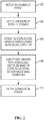
- FIG. 2 illustrates a method for vascular disease detection using a recurrent neural network according to an embodiment of the present invention.
- a 3D computed tomography angiography (CTA) image of the patient is received.
- the CTA image includes at least one vessel of interest (e.g., coronary artery, renal artery, cerebral artery, etc.) of the patient.
- the CTA image can be received directly from a CT scanner or can be received by loading a previously stored CTA image.
- a centerline of a vessel is detected in the CTA image.
- the centerline of the vessel is automatically detected in the CTA image, for example using a centerline tracing method or a machine learning based centerline detection method.
- the vessel centerline can be detected in the CTA image using a combined model-driven and data-driven method, as described in U.S. Patent Application No. 9,129,417 , entitled “Method and System for Coronary Artery Centerline Extraction", which is incorporated herein by reference in its entirety.
- the vessel centerline can be detected in the CTA image using the method described in U.S. Patent Application No.
- 2D cross section images are extracted from the 3D CTA image at a plurality of sampling points along the vessel centerline.
- the vessel centerline is sampled to establish a plurality of sample points along the vessel centerline.
- a uniformly sampling distribution may be used to define evenly spaced sampling points, but the present invention is not limited thereto and other possible sampling distributions may be used depending on the vessel of interest.
- a respective 2D cross-section image is extracted from the 3D CTA image at each sampling point on the vessel centerline.
- Each 2D cross-section image can be a predetermined size image centered at the respective sampling point and aligned with a tangent direction to the vessel centerline at that sampling point.
- each sampling point along the vessel centerline is classified based on the extracted 2D cross-section images using a trained recurrent neural network (RNN).
- RNN recurrent neural network
- the classification of each sampling point by the RNN depends not only on the cross-section image extracted at that sampling point, but also on the cross-section images extracted at the other sampling points as well.
- RNNs have typically been used for prediction tasks from sequential information with multiple time points.
- the cross-section images extracted from various spatial locations (i.e., respective centerline sampling points) in the CTA image are input to an RNN, which processes the spatial sequence of images as if they were a dynamic time-sequence of images.
- RNN architectures such as long short-term memory (LSTM) or gated recurrent unit (GRU), can be used to classify the sampling points of the vessel centerline.
- LSTM long short-term memory
- GRU gated recurrent unit
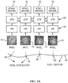
- FIG. 3A illustrates an RNN architecture using a bi-directional LSTM and a convolutional neural network (CNN) for vessel abnormality detection according to an embodiment of the present invention.
- 2D cross-section images 312, 314, 316, and 318 are extracted at sampling points 302, 304, 306, and 308, respectively, along a vessel centerline 300.
- Each of the 2D cross-section images 312, 314, 316, and 318 can be considered as corresponding to time point of an RNN input.
- the 2D cross-section images 312, 314, 316, and 318 are connected to an RNN layer 330 through convolutional neural network (CNN) 320.
- CNN convolutional neural network
- a fully connected layer may be used in place of the CNN 320.
- the CNN 320 takes image of a fixed size. Accordingly, the 2D cross-section images 312, 314, 316, and 318 input to the CNN 320 can be predetermined size image patches extracted larger 2D cross-section images.
- the CNN 320 encodes each input image 312,314,316, and 318 into a feature vector that is a high-level semantic representation of the input image, and the feature vector extracted for each 2D cross-section image 312, 314, 316, and 318 by the CNN 320 is input to the RNN layer 330. It is to be understood that the same trained CNN 320 (i.e., having the same learned weights) is applied to each of the 2D cross-section images 312, 314, 316, and 318.
- the RNN layer 330 inputs the feature vector extracted by the CNN 320 for each of the 2D cross-section images 312, 314, 316, and 318 and outputs a classification result for each of the corresponding sampling points 302, 304, 306, and 308 of the vessel centerline 300.
- the classification result may be a binary classification of normal or abnormal, as shown in FIG. 3A .
- the classification result may also be a multi-class label, e.g., for plaque type classification (e.g., calcified, non-calcified, mixed), or a continuous value, e.g., for stenosis grading regression.
- the RNN layer is implemented as a bi-directional LSTM 330.
- a bi-directional RNN is constructed where both the original (forward direction) and reversed (backward direction) inputs are fed into the RNN.
- FIG. 3B illustrates the RNN architecture of FIG. 3A with a detailed depiction of the operation of the bi-directional LSTM layer 330. As shown in FIG.
- the bi-directional LSTM layer 330 includes a forward direction LSTM layer 430a and a backward direction LSTM layer 430b.
- the forward LSTM layer 430a and the backward LSTM layer 430b are first and second trained LSTMs with different learned weights.
- the features extracted by the CNN 320 for each 2D cross-section image 312, 314, 316, and 318 are input to both the forward LSTM layer 430a and the backward LSTM layer 430b.
- the forward LSTM layer starts by classifying a first sampling point (e.g., sampling point 302) in the sequence based on the corresponding 2D cross-section image (e.g., image 312), and then sequentially classifies each subsequent sampling point in a forward direction (e.g., from ostium to distal end) along the vessel centerline based on the corresponding 2D cross-section image and image information from the cross-section images corresponding to the previously classified sampling points.
- a first sampling point e.g., sampling point 302
- a forward direction e.g., from ostium to distal end
- the backward LSTM layer starts by classifying a final sampling point (e.g., sampling point 308) in the sequence based on the corresponding 2D cross-section image (e.g., image 318), and then sequentially classifies each preceding sampling point in a backward direction (e.g., from distal end to ostium) along the centerline based on the corresponding 2D cross-section image and image information from the cross-section images corresponding to the previously classified sampling points. That is, the forward LSTM layer starts at one end of the vessel centerline 300 and works forward and the backward LSTM layer starts at the other end of the vessel centerline 300 and works backward. The forward LSTM and the backward LSTM.
- a final sampling point e.g., sampling point 308
- a backward direction e.g., from distal end to ostium
- the forward LSTM output and the backward LSTM output for each sampling point are combined (e.g., by concatenating, summing, or averaging (weighted or unweighted) the forward and backward outputs) in order to determine the final classification results 332, 334, 336, and 338.
- the forward and backward LSTMs directly output the classification labels, the results of two LSTMs can be summed or averaged.
- 1-2 neural network layers can be added between the LSTM output and the final classification label. In this case, the outputs of two LSTMs can be concatenated into a longer feature vector as input to the additional neural network layers.
- the RNN/LSTM architecture shown in FIG. 3A and 3B may be modified to incorporate multi-scale image information, as described below in connection with the method of FIG. 6 .
- each sampling point can be classified as normal or abnormal.
- the RNN architecture may output a multi-class label for each sampling point for plaque type classification.
- each sampling point may be classified as one of normal, calcified plaque, non-calcified plaque, or mixed plaque.
- the RNN architecture may output a numerical value for each sampling point. This numerical value can be used to determine the abnormal or normal classification as well as a severity (e.g., mild, moderate, critical) for each sampling point.
- the classification results may be visualized in various ways.
- locations along the vessel centerline classified as abnormal can be provided to the user or highlighted in a CTA image displayed on a display device, along with characterizations of the type of plaque and/or the severity of the abnormality.
- the numerical values determined for the sampling points can be converted to a color map which can be displayed to provide a visualization of vascular disease along the entire vessel.
- input from a static CTA image is formulated as a dynamic sequence.
- image patch is sampled perpendicular to the centerline trajectory. Moving along the centerline from ostium to distal end, a dynamic sequence of cross-section images is generated.
- the length of the sequence may vary from one case to another.
- Most machine learning algorithms only accept an input vector with a fixed length.
- the input image size for most machine learning algorithms is set as a hyperparameter, which is fixed after training. However, the object being detected may have significantly different size across patients or even within the same sequence.
- the present inventors have recognized that a method that can handle variations in object size as well as input sequence length is desirable.
- a window (with a fixed length) based approach is often used to handle an input with variable length. For example, it is possible to consider only a current frame together with n frames before and after the current frame, resulting in an observation window of 2 n + 1. With an input of a fixed length, many existing machine learning algorithms (e.g., AdaBoost or Support Vector Machine) can be applied. However, the length of the event (e.g., coronary artery stenosis) being detected may vary significantly, and a fixed window may be too small for some datasets, but too large for others.
- Embodiments of the present invention use LSTM to handle input with variable length for vascular disease (e.g., coronary plaque) detection, as illustrated in FIGS. 3A and 3B .
- vascular disease e.g., coronary plaque
- LSTM considers all input until the current frame to make a prediction. Furthermore, as illustrated in FIGS. 3A and 3B , embodiments of the present invention use bi-directional LSTM, which utilizes two LSTM layers, one handling forward observation of a sequence and one handling backward observation of the sequence. Accordingly, by using bi-direction LSTM, the whole input is observed to predict if a current position (sampling point) contains or coronary plaque or not.
- a CNN is used to encode each input image into a feature vector, which is a high level semantic representation of the input image.
- the CNN takes an image with a fixed size.
- the object being detected/classified may have significantly different sizes across patients or even with the same sequence.
- the optimal field-of-view (FoV) to perform classification for each sequence or each frame may be different.
- a recurrent neural network is an architecture that can handle input with variable length.
- FIG. 4 illustrates an RNN 400 and an unrolled representation 410 of the RNN 400.
- an RNN contains a feedback loop in its memory cell, as shown in RNN 400 of FIG. 4 .
- the unrolled representation 410 of the RNN 400 in FIG. 4 given an input sequence [ X 0 ,X 1 , ... X t ], an RNN can be "unrolled" t times to generate a loopless architecture matching the input length.
- An unrolled network has t + 1 layers and each layer is identical (i.e., each layer shares the same learned weights).
- an RNN can be trained based on ground truth training samples with back-propagation, similar to a conventional feed-forward neural network.
- the only difference in the training is that the weights of each copy of the network need to be averaged to ensure that all copies are identical after the update.
- One challenge for training is that, during the gradient back-propagation phase, the gradient signal can end up being multiplied a large number of times (as many as the number of time steps). This leads to either gradient vanishing (when the magnitude of the gradient signal is smaller than 1) or gradient explosion (when the gradient magnitude is greater than 1). Under gradient vanishing, the network will not be effectively updated; while under gradient explosion, the training process diverges. Therefore, conventional RNN has an issue to train with a long sequence, and thus has a limitation in learning long term memory.
- FIG. 5 illustrates an LSTM network.
- the LSTM network 500 includes an input gate 502, an output gate 504, and a forget gate 506, which control the input, output, and memory state, respectively.
- the memory state is C t- 1
- the output state is h t -1
- the input state at time t is X t .
- each sampling point is considered to be a "time step" (and each 2D cross-section image patch the corresponding input) even though the sampling points are a spatial sequence, not a time sequence.
- LSTM has typically been used for applications involving 1D data sequences.
- a compact high-level representation of the image is extracted, e.g., using a CNN (as shown in FIGS. 3A and 3B ).
- the CNN takes an image with fixed size as input (otherwise padding or cropping is performed to normalize the size).
- the object of interest may have quite different sizes in different sequences.
- the size of the object may even vary within the same sequence.
- a fixed field-of-view (FoV) may not be optimal to handle such a large variation.
- multiscale image information can be incorporated in the LSTM framework.
- FIG. 6 illustrates a method for classifying a sequence of medical images using a multiscale spatio-temporal LSTM according to an embodiment of the present invention.
- the method of FIG. 6 is described using LSTM architecture, the method is not limited to LSTM and may be applied to RNN in general.
- the method of FIG. 6 can be used in step 208 of FIG. 2 with the architecture of FIGS. 3A and 3B to perform detection and characterization of vascular disease.
- the present invention is not limited thereto, and the method of FIG. 6 may be applied to 2D or 3D medical images to perform other medical image classification tasks as well.
- a sequence of medical images is received.
- the sequence of medical images is the 2D cross-section images (or image patches) extracted at the sampling points of the vessel centerline.
- the sequence can be a sequence of images extracted at various spatial locations from a static image (as in the vascular disease detection embodiment), or a time sequence of 2D or 3D medical images.
- the medical images can be received directly from a medical image acquisition device or may be received by loading a previously stored sequence of medical images.
- an image pyramid with multiple reduced resolution images is generated for each image in the sequence of medical images.
- An image pyramid is a scale space representation of the input image data.
- an image pyramid with multiple reduced resolution images is generated for each 2D cross-section image.
- a three-level image pyramid may have reduced resolution images of 8 mm, 4 mm, and 2 mm from coarse to fine.
- An image patch with a fixed size in pixels (or voxels) actually has a different field-of-view (FoV) at different resolutions. For example, a patch with 15 x 15 pixels has a FoV of 120 x 120 mm 2 at 8 mm resolution, but an FoV of 30 x 30 mm 2 at 2 mm resolution.
- the sequence of medical images is classified based on the multiple reduced resolution images generated for each image in the sequence of medical images using a trained LSTM architecture.
- the LSTM architecture outputs a classification result for each "time step" (e.g., each sampling point in the vascular disease detection embodiment).
- the LSTM architecture utilizes a bi-directional LSTM.
- FIGS. 7 , 8 , and 9 illustrate alterative embodiments for incorporating the multi-resolution image information into the LSTM framework.
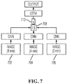
- FIG. 7 illustrates a concatenated multiscale spatio-temporal LSTM according to an embodiment of the present invention.
- a concatenation operation 708 is used to concatenate CNN features extracted from image patches 702, 704, and 706 with different image resolutions (e.g., 8 mm, 4 mm, and 2 mm, respectively) into one long feature vector.
- the concatenated feature vector then is input to the LSTM via the input gate 710 of the LSTM.
- An advantage of this embodiment is that there is no change to the LSTM architecture, but it is trained using concatenated features extracted from multi-resolution input images.
- a disadvantage with this embodiment is that the most discriminative features may be overwhelmed by less discriminative features, which can limit the overall improvement on recognition accuracy achieved.
- FIG. 8 illustrates a gated multiscale spatio-temporal LSTM according to an embodiment of the present invention.
- the "gating" of the LSTM can be extended to the image pyramid images.
- a separate gate can be used (and a separate gating function learned) for each pyramid level.
- gates 812, 814, and 816 control the input of the CNN features for the image patches 802, 814, and 816, respectively with different image resolutions (e.g., 8 mm, 4 mm, and 2 mm, respectively).
- a summation operation 820 is used to add the input signals from the different resolutions together, which does not change the input dimension (different from the concatenation operation of FIG. 7 ).
- This embodiment allows the LSTM to be trained to select the right "scale” by ignoring information from other resolutions.
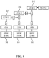
- FIG. 9 illustrates an integrated concatenated and gated multiscale spatio-temporal LSTM according to an embodiment of the present invention.
- the integration of multiscale image information is limited to the input and a single LSTM is used to perform learning.
- the multiscale image information is integrated more tightly. As shown in FIG.
- a respective LSTM (LSTM 1 912, LSTM 2 914, and LSTM 3 916) is trained for each pyramid level image 902, 904, and 906, and the output of a lower level LSTM is fed to the next level LSTM.
- the higher level LSTM takes two inputs: one from the image at it corresponding pyramid level and the other from the lower level LSTM. These two input signals can be integrated by either concatenation or gating.
- the lower level LSTM output can be used to control the gates of the higher level LSTM.
- the higher level LSTM takes one input from its own pyramid level image, but the gates are controlled by three signals: current input, its own previous output, and current output of the lower level LSTM.
- the classification results are output.
- the classification results for each "time step" (or each spatial location) (e.g., each sampling point on the vessel centerline) can be output, for example, by displaying the classification results on a display device of a computer system.
- the detection accuracy of vascular disease can be improved in the presence of varying vessel (e.g., coronary artery) size.
- the method of FIG. 6 can also be used for other medical imaging classification / detection applications, as well.
- the methods of FIG. 2 and FIG. 6 are utilized to detect and characterize vascular disease (abnormalities) from a CTA image of a patient. These methods may be similarly applied for other vascular classification applications, as well. For example, the above described methods may be similarly applied to perform vessel lumen and outer wall cross-sectional diameter or area estimation. Most quantitative vascular analysis methods use a 3D model of the vessel to calculate diameter/area. Estimating vessel diameter directly from the image data can remove the need to compute a 3D model of the vessel, which is a very time consuming task. The above described methods may also be similarly applied to detecting image artifacts, such as motion artifacts, blooming artifacts due to calcification and/or metal implants, and partial volume effects.
- image artifacts such as motion artifacts, blooming artifacts due to calcification and/or metal implants, and partial volume effects.
- Automated detection of vessel image artifacts in medical images as soon as they are acquired can greatly benefit the clinical workflow by flagging such images for re-acquisition while the patient is still on the table.
- the detection of artifacts may also be used to provide feedback to the image reconstruction algorithm to determine an optimal set of reconstruction parameters.
- the above described methods may also be similarly applied to detection of vessel centerline leakage. Methods have been proposed to extract vessel centerlines in medical images with very high sensitivity, but at the expense of false branches leaking into nearby structures or other vessels. There is a need to distinguish true centerlines from leakage.
- the above described methods can be used to train a centerline leakage detector.
- the above described methods may also be similarly applied to detection of vascular devices, such as stents, grafts, coils, and clips in the vasculature.
- Computer 1002 contains a processor 1004, which controls the overall operation of the computer 1002 by executing computer program instructions which define such operation.
- the computer program instructions may be stored in a storage device 1012 (e.g., magnetic disk) and loaded into memory 1010 when execution of the computer program instructions is desired.
- An image acquisition device 1020 such as a CT scanner, can be connected to the computer 1002 to input image data to the computer 1002. It is possible to implement the image acquisition device 1020 and the computer 1002 as one device. It is also possible that the image acquisition device 1020 and the computer 1002 communicate wirelessly through a network. In a possible embodiment, the computer 1002 can be located remotely with respect to the image acquisition device 1020 and the method steps described herein can be performed as part of a server or cloud based service. In this case, the method steps may be performed on a single computer or distributed between multiple networked computers.
- the computer 1002 also includes one or more network interfaces 1006 for communicating with other devices via a network.
- the computer 1002 also includes other input/output devices 1008 that enable user interaction with the computer 1002 (e.g., display, keyboard, mouse, speakers, buttons, etc.).
- Such input/output devices 1008 may be used in conjunction with a set of computer programs as an annotation tool to annotate volumes received from the image acquisition device 1020.
- FIG. 10 is a high level representation of some of the components of such a computer for illustrative purposes.
Landscapes
- Engineering & Computer Science (AREA)
- Theoretical Computer Science (AREA)
- Physics & Mathematics (AREA)
- General Physics & Mathematics (AREA)
- General Health & Medical Sciences (AREA)
- Health & Medical Sciences (AREA)
- Evolutionary Computation (AREA)
- Artificial Intelligence (AREA)
- Life Sciences & Earth Sciences (AREA)
- Computer Vision & Pattern Recognition (AREA)
- Molecular Biology (AREA)
- Biomedical Technology (AREA)
- Data Mining & Analysis (AREA)
- Software Systems (AREA)
- Computing Systems (AREA)
- Multimedia (AREA)
- General Engineering & Computer Science (AREA)
- Biophysics (AREA)
- Mathematical Physics (AREA)
- Computational Linguistics (AREA)
- Medical Informatics (AREA)
- Radiology & Medical Imaging (AREA)
- Nuclear Medicine, Radiotherapy & Molecular Imaging (AREA)
- Quality & Reliability (AREA)
- Databases & Information Systems (AREA)
- Biodiversity & Conservation Biology (AREA)
- Geometry (AREA)
- Bioinformatics & Cheminformatics (AREA)
- Bioinformatics & Computational Biology (AREA)
- Evolutionary Biology (AREA)
- Image Analysis (AREA)
- Apparatus For Radiation Diagnosis (AREA)
Abstract
Description
- The present invention relates to vascular disease detection and characterization in medical images, and more particularly, to vascular disease detection and characterization in medical images using recurrent neural networks.
- Recent generations of computed tomography (CT) scanners enable the acquisition of high quality CT angiography (CTA) images, which can be used as an alternative to invasive angiography for ruling out vascular diseases such as coronary stenosis and plaque. This has led to the development of various algorithms for automated detection of vascular diseases in CTA images. However, due to the varying length of vascular branches, such algorithms typically rely on only local image features extracted along vascular branches, and hence are only able to produce local predictions that independently characterize centerline points along a vascular branch, but do not take into account an overall dependency between image features and predictions along the vascular branch.
- The present invention provides a method and system for automated vascular disease detection and characterization in medical images using recurrent neural networks. Embodiments of the present invention exploit sequential image context information embedded along vascular branches to detect and characterize vascular abnormalities in computed tomography angiography (CTA) images of a patient using recurrent neural networks (RNN).
- The present invention provides a method for vascular disease detection using a recurrent neural network, comprising:
- extracting a plurality of 2D cross-section image patches from a 3D computed tomography angiography (CTA) image, wherein each of 2D cross-section image patches is extracted at a respective one of a plurality of sampling points along a vessel centerline of a vessel of interest in the 3D CTA image; and
- detecting vascular abnormalities in the vessel of interest by classifying each of the plurality of sampling points along the vessel centerline based on the plurality of 2D cross-section image patches using a trained recurrent neural network (RNN).
- According to a preferred embodiment of the method, the method further comprising:
- detecting the vessel centerline of the vessel of interest in the 3D CTA image.
- According to another preferred embodiment of the method, detecting vascular abnormalities in the vessel of interest by classifying each of the plurality of sampling points along the vessel centerline based on the plurality of 2D cross-section image patches using a trained recurrent neural network (RNN) comprises:
- encoding each of the 2D cross-section image patches into a respective feature vector using a trained convolutional neural network (CNN); and
- classifying each of the plurality of sampling points along the vessel centerline based on the feature vectors corresponding to the plurality of 2D cross-section image patches using a trained bi-directional RNN.
- The bi-directional RNN can be a bi-directional long short-term memory (LSTM) network, and classifying each of the plurality of sampling points along the vessel centerline based on the feature vectors corresponding to the plurality of 2D cross-section image patches using a trained bi-directional RNN can comprise:
- inputting the feature vectors corresponding to the plurality of 2D cross-section image patches to a forward LSTM network and a backward LSTM network;
- sequentially classifying each of the plurality of sampling points along the vessel centerline in a forward direction from a first sampling point to an nth sampling point using the forward LSTM network, wherein the forward LSTM network classifies each sampling point based on the feature vector corresponding to the 2D cross-section image extracted at that sampling point and the feature vectors corresponding to the 2D cross-section images extracted at sampling points previously classified by the forward LSTM network;
- sequentially classifying each of the plurality of sampling points along the vessel centerline in a backward direction from the nth sampling point to the first sampling point using the backward LSTM network, wherein the backward LSTM network classifies each sampling point based on the feature vector corresponding to the 2D cross-section image extracted at that sampling point and the feature vectors corresponding to the 2D cross-section images extracted at sampling points previously classified by the backward LSTM network; and
- combining classification results output by the forward LSTM and classification results output by the backward LSTM for each of the plurality of sampling points.
- According to a preferred embodiment of the method, detecting vascular abnormalities in the vessel of interest by classifying each of the plurality of sampling points along the vessel centerline based on the plurality of 2D cross-section image patches using a trained recurrent neural network (RNN) comprises:
- generating multiscale image information for each of the 2D cross-section image patches; and
- classifying each of the plurality of sampling points along the vessel centerline based on the multiscale image information generated for the plurality of 2D cross-section image patches using the trained RNN.
- Generating multiscale image information for each of the 2D cross-section image patches can comprise:
- generating an image pyramid with multiple reduced resolution image patches for each of the 2D cross-section image patches.
- The trained RNN can be a bi-directional long short-term memory (LSTM) network, and classifying each of the plurality of sampling points along the vessel centerline based on the multiscale image information generated for the plurality of 2D cross-section image patches using the trained RNN can comprise, for each of the plurality of sampling points along the vessel centerline:
- encoding each of multiple reduced resolution image patches generated for the 2D cross-section image patch extracted at a current sampling point into a respective feature vector for each resolution using a respective trained convolutional neural network (CNN) for each resolution;
- concatenating the feature vectors encoded from all of the multiple reduced resolution images into a concatenated feature vector; inputting the concatenated feature vector the current sampling point based on a learned input gating function of the bi-directional LSTM; and
- classifying the current sampling point based on the input concatenated feature vector for the current sampling point and a memory state of the bi-directional LSTM at the current sampling point.
- The trained RNN can be a bi-directional long short-term memory (LSTM) network, and classifying each of the plurality of sampling points along the vessel centerline based on the multiscale image information generated for the plurality of 2D cross-section image patches using the trained RNN can comprise, for each of the plurality of sampling points along the vessel centerline:
- encoding each of multiple reduced resolution image patches generated for the 2D cross-section image patch extracted at a current sampling point into a respective feature vector for each resolution using a respective trained convolutional neural network (CNN) for each resolution;
- inputting the feature vector encoded for each resolution based on a respective learned gating function of the bi-directional LSTM for each resolution;
- summing the feature vectors input by the respective learned gating functions for each resolution; and
- classifying the current sampling point based on the summed input feature vectors for the current sampling point and a memory state of the bi-directional LSTM at the current sampling point.
- Classifying each of the plurality of sampling points along the vessel centerline based on the multiscale image information generated for the plurality of 2D cross-section image patches using the trained RNN can comprise, for each of the plurality of sampling points along the vessel centerline:
- encoding each of multiple reduced resolution image patches generated for the 2D cross-section image patch extracted at a current sampling point into a respective feature vector for each resolution using a respective trained convolutional neural network (CNN) for each resolution;
- inputting the encoded feature vector for each resolution to a respective trained long short-term memory (LSTM) network for each resolution; and
- sequentially performing classification of the current sample point by the respective trained LSTM for each resolution, starting with a lowest resolution level LSTM, wherein an output of each LSTM other than a highest resolution level LSTM is input to a subsequent LSTM at a next resolution level and the highest resolution level LSTM outputs a classification result for the current sampling point.
- According to a preferred embodiment of the method, detecting vascular abnormalities in the vessel of interest by classifying each of the plurality of sampling points along the vessel centerline based on the plurality of 2D cross-section image patches using a trained recurrent neural network (RNN) comprises:
- detecting vascular abnormalities in the vessel of interest and classifying a type of the vascular abnormalities in the vessel of interest by classifying each of the plurality of sampling points along the vessel centerline based on the plurality of 2D cross-section image patches using a trained recurrent neural network (RNN).
- According to another preferred embodiment of the method, wherein detecting vascular abnormalities in the vessel of interest by classifying each of the plurality of sampling points along the vessel centerline based on the plurality of 2D cross-section image patches using a trained recurrent neural network (RNN) comprises:
- detecting vascular abnormalities in the vessel of interest and classifying a severity of the vascular abnormalities in the vessel of interest by classifying each of the plurality of sampling points along the vessel centerline based on the plurality of 2D cross-section image patches using a trained recurrent neural network (RNN).
- The present invention further provides an apparatus for vascular disease detection using a recurrent neural network, comprising:
- means for extracting a plurality of 2D cross-section image patches from a 3D computed tomography angiography (CTA) image, wherein each of 2D cross-section image patches is extracted at a respective one of a plurality of sampling points along a vessel centerline of a vessel of interest in the 3D CTA image; and
- means for detecting vascular abnormalities in the vessel of interest by classifying each of the plurality of sampling points along the vessel centerline based on the plurality of 2D cross-section image patches using a trained recurrent neural network (RNN).
- According to a preferred embodiment of the apparatus, the means for detecting vascular abnormalities in the vessel of interest by classifying each of the plurality of sampling points along the vessel centerline based on the plurality of 2D cross-section image patches using a trained recurrent neural network (RNN) comprises:
- means for encoding each of the 2D cross-section image patches into a respective feature vector using a trained convolutional neural network (CNN); and
- means for classifying each of the plurality of sampling points along the vessel centerline based on the feature vectors corresponding to the plurality of 2D cross-section image patches using a trained bi-directional RNN.
- The bi-directional RNN can be a bi-directional long short-term memory (LSTM) network, and the means for classifying each of the plurality of sampling points along the vessel centerline based on the feature vectors corresponding to the plurality of 2D cross-section image patches using a trained bi-directional RNN can comprise:
- means for inputting the feature vectors corresponding to the plurality of 2D cross-section image patches to a forward LSTM network and a backward LSTM network;
- means for sequentially classifying each of the plurality of sampling points along the vessel centerline in a forward direction from a first sampling point to an nth sampling point using the forward LSTM network, wherein the forward LSTM network classifies each sampling point based on the feature vector corresponding to the 2D cross-section image extracted at that sampling point and the feature vectors corresponding to the 2D cross-section images extracted at sampling points previously classified by the forward LSTM network;
- means for sequentially classifying each of the plurality of sampling points along the vessel centerline in a backward direction from the nth sampling point to the first sampling point using the backward LSTM network, wherein the backward LSTM network classifies each sampling point based on the feature vector corresponding to the 2D cross-section image extracted at that sampling point and the feature vectors corresponding to the 2D cross-section images extracted at sampling points previously classified by the backward LSTM network; and
- means for combining classification results output by the forward LSTM and classification results output by the backward LSTM for each of the plurality of sampling points.
- According to a preferred embodiment of the apparatus, the means for detecting vascular abnormalities in the vessel of interest by classifying each of the plurality of sampling points along the vessel centerline based on the plurality of 2D cross-section image patches using a trained recurrent neural network (RNN) comprises:
- means for generating multiscale image information for each of the 2D cross-section image patches; and
- means for classifying each of the plurality of sampling points along the vessel centerline based on the multiscale image information generated for the plurality of 2D cross-section image patches using the trained RNN.
- The means for generating multiscale image information for each of the 2D cross-section image patches can comprise:
- means for generating an image pyramid with multiple reduced resolution image patches for each of the 2D cross-section image patches.
- The trained RNN can be a bi-directional long short-term memory (LSTM) network, and the means for classifying each of the plurality of sampling points along the vessel centerline based on the multiscale image information generated for the plurality of 2D cross-section image patches using the trained RNN can comprise, for each of the plurality of sampling points along the vessel centerline:
- means for encoding each of multiple reduced resolution image patches generated for the 2D cross-section image patch extracted at a current sampling point into a respective feature vector for each resolution using a respective trained convolutional neural network (CNN) for each resolution;
- means for concatenating the feature vectors encoded from all of the multiple reduced resolution images into a concatenated feature vector;
- means for inputting the concatenated feature vector the current sampling point based on a learned input gating function of the bi-directional LSTM; and
- means for classifying the current sampling point based on the input concatenated feature vector for the current sampling point and a memory state of the bi-directional LSTM at the current sampling point.
- The trained RNN can be a bi-directional long short-term memory (LSTM) network, and the means for classifying each of the plurality of sampling points along the vessel centerline based on the multiscale image information generated for the plurality of 2D cross-section image patches using the trained RNN can comprise, for each of the plurality of sampling points along the vessel centerline:
- means for encoding each of multiple reduced resolution image patches generated for the 2D cross-section image patch extracted at a current sampling point into a respective feature vector for each resolution using a respective trained convolutional neural network (CNN) for each resolution;
- means for inputting the feature vector encoded for each resolution based on a respective learned gating function of the bi-directional LSTM for each resolution;
- means for summing the feature vectors input by the respective learned gating functions for each resolution; and
- means for classifying the current sampling point based on the summed input feature vectors for the current sampling point and a memory state of the bi-directional LSTM at the current sampling point.
- The means for classifying each of the plurality of sampling points along the vessel centerline based on the multiscale image information generated for the plurality of 2D cross-section image patches using the trained RNN can comprise, for each of the plurality of sampling points along the vessel centerline:
- means for encoding each of multiple reduced resolution image patches generated for the 2D cross-section image patch extracted at a current sampling point into a respective feature vector for each resolution using a respective trained convolutional neural network (CNN) for each resolution;
- means for inputting the encoded feature vector for each resolution to a respective trained long short-term memory (LSTM) network for each resolution; and
- means for sequentially performing classification of the current sample point by the respective trained LSTM for each resolution, starting with a lowest resolution level LSTM, wherein an output of each LSTM other than a highest resolution level LSTM is input to a subsequent LSTM at a next resolution level and the highest resolution level LSTM outputs a classification result for the current sampling point.
- The present invention further provides a non-transitory computer readable medium storing computer program instructions for vascular disease detection using a recurrent neural network, the computer program instructions when executed by a processor cause the processor to perform operations comprising:
- extracting a plurality of 2D cross-section image patches from a 3D computed tomography angiography (CTA) image, wherein each of 2D cross-section image patches is extracted at a respective one of a plurality of sampling points along a vessel centerline of a vessel of interest in the 3D CTA image; and
- detecting vascular abnormalities in the vessel of interest by classifying each of the plurality of sampling points along the vessel centerline based on the plurality of 2D cross-section image patches using a trained recurrent neural network (RNN).
- According to a preferred embodiment of the non-transitory computer readable medium, detecting vascular abnormalities in the vessel of interest by classifying each of the plurality of sampling points along the vessel centerline based on the plurality of 2D cross-section image patches using a trained recurrent neural network (RNN) comprises:
- encoding each of the 2D cross-section image patches into a respective feature vector using a trained convolutional neural network (CNN); and
- classifying each of the plurality of sampling points along the vessel centerline based on the feature vectors corresponding to the plurality of 2D cross-section image patches using a trained bi-directional RNN.
- The bi-directional RNN can be a bi-directional long short-term memory (LSTM) network, and classifying each of the plurality of sampling points along the vessel centerline based on the feature vectors corresponding to the plurality of 2D cross-section image patches using a trained bi-directional RNN can comprise:
- inputting the feature vectors corresponding to the plurality of 2D cross-section image patches to a forward LSTM network and a backward LSTM network;
- sequentially classifying each of the plurality of sampling points along the vessel centerline in a forward direction from a first sampling point to an nth sampling point using the forward LSTM network, wherein the forward LSTM network classifies each sampling point based on the feature vector corresponding to the 2D cross-section image extracted at that sampling point and the feature vectors corresponding to the 2D cross-section images extracted at sampling points previously classified by the forward LSTM network;
- sequentially classifying each of the plurality of sampling points along the vessel centerline in a backward direction from the nth sampling point to the first sampling point using the backward LSTM network, wherein the backward LSTM network classifies each sampling point based on the feature vector corresponding to the 2D cross-section image extracted at that sampling point and the feature vectors corresponding to the 2D cross-section images extracted at sampling points previously classified by the backward LSTM network; and
- combining classification results output by the forward LSTM and classification results output by the backward LSTM for each of the plurality of sampling points.
- According to a preferred embodiment of the non-transitory computer readable medium, detecting vascular abnormalities in the vessel of interest by classifying each of the plurality of sampling points along the vessel centerline based on the plurality of 2D cross-section image patches using a trained recurrent neural network (RNN) comprises:
- generating multiscale image information for each of the 2D cross-section image patches; and
- classifying each of the plurality of sampling points along the vessel centerline based on the multiscale image information generated for the plurality of 2D cross-section image patches using the trained RNN.
- Generating multiscale image information for each of the 2D cross-section image patches can comprise:
- generating an image pyramid with multiple reduced resolution image patches for each of the 2D cross-section image patches.
- The trained RNN can a bi-directional long short-term memory (LSTM) network, and classifying each of the plurality of sampling points along the vessel centerline based on the multiscale image information generated for the plurality of 2D cross-section image patches using the trained RNN can comprise, for each of the plurality of sampling points along the vessel centerline:
- encoding each of multiple reduced resolution image patches generated for the 2D cross-section image patch extracted at a current sampling point into a respective feature vector for each resolution using a respective trained convolutional neural network (CNN) for each resolution;
- concatenating the feature vectors encoded from all of the multiple reduced resolution images into a concatenated feature vector;
- inputting the concatenated feature vector the current sampling point based on a learned input gating function of the bi-directional LSTM; and
- classifying the current sampling point based on the input concatenated feature vector for the current sampling point and a memory state of the bi-directional LSTM at the current sampling point.
- Alternatively or additionally, the trained RNN can be a bi-directional long short-term memory (LSTM) network, and classifying each of the plurality of sampling points along the vessel centerline based on the multiscale image information generated for the plurality of 2D cross-section image patches using the trained RNN can comprise, for each of the plurality of sampling points along the vessel centerline:
- encoding each of multiple reduced resolution image patches generated for the 2D cross-section image patch extracted at a current sampling point into a respective feature vector for each resolution using a respective trained convolutional neural network (CNN) for each resolution;
- inputting the feature vector encoded for each resolution based on a respective learned gating function of the bi-directional LSTM for each resolution;
- summing the feature vectors input by the respective learned gating functions for each resolution; and
- classifying the current sampling point based on the summed input feature vectors for the current sampling point and a memory state of the bi-directional LSTM at the current sampling point.
- Classifying each of the plurality of sampling points along the vessel centerline based on the multiscale image information generated for the plurality of 2D cross-section image patches using the trained RNN can comprise, for each of the plurality of sampling points along the vessel centerline:
- encoding each of multiple reduced resolution image patches generated for the 2D cross-section image patch extracted at a current sampling point into a respective feature vector for each resolution using a respective trained convolutional neural network (CNN) for each resolution;
- inputting the encoded feature vector for each resolution to a respective trained long short-term memory (LSTM) network for each resolution; and
- sequentially performing classification of the current sample point by the respective trained LSTM for each resolution, starting with a lowest resolution level LSTM, wherein an output of each LSTM other than a highest resolution level LSTM is input to a subsequent LSTM at a next resolution level and the highest resolution level LSTM outputs a classification result for the current sampling point.
- In one embodiment of the present invention, a plurality of 2D cross-section image patches are extracted from a 3D computed tomography angiography (CTA) image, wherein each of 2D cross-section image patches is extracted at a respective one of a plurality of sampling points along a vessel centerline of a vessel of interest in the 3D CTA image. Vascular abnormalities in the vessel of interest are detected by classifying each of the plurality of sampling points along the vessel centerline based on the plurality of 2D cross-section image patches using a trained recurrent neural network (RNN).
- These and other advantages of the invention will be apparent to those of ordinary skill in the art by reference to the following detailed description and the accompanying drawings.
-
-
FIG. 1 illustrates an example of vascular disease along a coronary artery; -
FIG. 2 illustrates a method for vascular disease detection using a recurrent neural network according to an embodiment of the present invention; -
FIG. 3A illustrates a recurrent neural network (RNN) architecture using a bi-directional long short-term memory (LSTM) and a convolutional neural network (CNN) for vessel abnormality detection according to an embodiment of the present invention; -
FIG. 3B illustrates the RNN architecture ofFIG. 3A with a detailed depiction of the operation of the bi-directional LSTM layer. -
FIG. 4 illustrates an RNN and an unrolled representation of the RNN; -
FIG. 5 illustrates an LSTM network; -
FIG. 6 illustrates a method for classifying a sequence of medical images using a multiscale spatio-temporal LSTM according to an embodiment of the present invention; -
FIG. 7 illustrates a concatenated multiscale spatio-temporal LSTM according to an embodiment of the present invention; -
FIG. 8 illustrates a gated multiscale spatio-temporal LSTM according to an embodiment of the present invention; -
FIG. 9 illustrates an integrated concatenated and gated multiscale spatio-temporal LSTM according to an embodiment of the present invention; and -
FIG. 10 is a high-level block diagram of a computer capable of implementing the present invention. - The present invention relates to a method and system for automated vascular disease detection and characterization in medical images using recurrent neural networks. Embodiments of the present invention are described herein to give a visual understanding of the vascular disease detection method and a method for classifying medical images using recurrent neural networks. A digital image is often composed of digital representations of one or more objects (or shapes). The digital representation of an object is often described herein in terms of identifying and manipulating the objects. Such manipulations are virtual manipulations accomplished in the memory or other circuitry / hardware of a computer system. Accordingly, is to be understood that embodiments of the present invention may be performed within a computer system using data stored within the computer system.
- Embodiments of the present invention detect and characterize vascular abnormalities, such as stenosis, plaques, etc., using sequential image context along a centerline of a vascular branch within a recurrent neural network (RNN) architecture.
FIG. 1 illustrates an example of vascular disease along a coronary artery. As shown inFIG. 1 , thecoronary artery 100 containsvascular abnormalities non-calcified plaques -
FIG. 2 illustrates a method for vascular disease detection using a recurrent neural network according to an embodiment of the present invention. Atstep 202, a 3D computed tomography angiography (CTA) image of the patient is received. The CTA image includes at least one vessel of interest (e.g., coronary artery, renal artery, cerebral artery, etc.) of the patient. The CTA image can be received directly from a CT scanner or can be received by loading a previously stored CTA image. - At
step 204, a centerline of a vessel is detected in the CTA image. In an advantageous implementation, the centerline of the vessel is automatically detected in the CTA image, for example using a centerline tracing method or a machine learning based centerline detection method. The vessel centerline can be detected in the CTA image using a combined model-driven and data-driven method, as described inU.S. Patent Application No. 9,129,417 U.S. Patent Application No. 7,953,266 , entitled "Robust Vessel Tree Modeling", which is incorporated herein by reference in its entirety. Other automatic or semi-automatic techniques for extracting vessel centerlines may be used as well. In another possible implementation, the vessel centerline may be manually annotated by a user using a user input device, such as a mouse. - At
step - At
step 208, each sampling point along the vessel centerline is classified based on the extracted 2D cross-section images using a trained recurrent neural network (RNN). According to an advantageous embodiment, the classification of each sampling point by the RNN depends not only on the cross-section image extracted at that sampling point, but also on the cross-section images extracted at the other sampling points as well. RNNs have typically been used for prediction tasks from sequential information with multiple time points. According to an advantageous embodiment of the present invention, the cross-section images extracted from various spatial locations (i.e., respective centerline sampling points) in the CTA image are input to an RNN, which processes the spatial sequence of images as if they were a dynamic time-sequence of images. Various types of RNN architectures, such as long short-term memory (LSTM) or gated recurrent unit (GRU), can be used to classify the sampling points of the vessel centerline. In an exemplary implementation described herein, LSTM is used, but the present invention is not limited thereto and any type of RNN architecture may be used. -
FIG. 3A illustrates an RNN architecture using a bi-directional LSTM and a convolutional neural network (CNN) for vessel abnormality detection according to an embodiment of the present invention. As shown inFIG. 3A ,2D cross-section images points vessel centerline 300. Each of the2D cross-section images FIG. 3A , the2D cross-section images RNN layer 330 through convolutional neural network (CNN) 320. In an alternative implementation, a fully connected layer may be used in place of theCNN 320. TheCNN 320 takes image of a fixed size. Accordingly, the2D cross-section images CNN 320 can be predetermined size image patches extracted larger 2D cross-section images. TheCNN 320 encodes each input image 312,314,316, and 318 into a feature vector that is a high-level semantic representation of the input image, and the feature vector extracted for each2D cross-section image CNN 320 is input to theRNN layer 330. It is to be understood that the same trained CNN 320 (i.e., having the same learned weights) is applied to each of the2D cross-section images - The
RNN layer 330 inputs the feature vector extracted by theCNN 320 for each of the2D cross-section images vessel centerline 300. The classification result may be a binary classification of normal or abnormal, as shown inFIG. 3A . The classification result may also be a multi-class label, e.g., for plaque type classification (e.g., calcified, non-calcified, mixed), or a continuous value, e.g., for stenosis grading regression. As shown inFIG. 3A , the RNN layer is implemented as abi-directional LSTM 330. In typical RNNs, the output of a time point is dependent only on previous time points. However, such a typical RNN architecture is not suitable for detecting and grading stenosis in vessel since a stenosis location and grading is clinically determined based on vessel lumen area/diameter both upstream and downstream of that location. According to an advantageous embodiment of the present invention, a bi-directional RNN is constructed where both the original (forward direction) and reversed (backward direction) inputs are fed into the RNN.FIG. 3B illustrates the RNN architecture ofFIG. 3A with a detailed depiction of the operation of thebi-directional LSTM layer 330. As shown inFIG. 3B , thebi-directional LSTM layer 330 includes a forward direction LSTM layer 430a and a backward direction LSTM layer 430b. The forward LSTM layer 430a and the backward LSTM layer 430b are first and second trained LSTMs with different learned weights. The features extracted by theCNN 320 for each2D cross-section image vessel centerline 300 and works forward and the backward LSTM layer starts at the other end of thevessel centerline 300 and works backward. The forward LSTM and the backward LSTM. The forward LSTM output and the backward LSTM output for each sampling point are combined (e.g., by concatenating, summing, or averaging (weighted or unweighted) the forward and backward outputs) in order to determine the final classification results 332, 334, 336, and 338. For example, if the forward and backward LSTMs directly output the classification labels, the results of two LSTMs can be summed or averaged. In another possible implementation, 1-2 neural network layers can be added between the LSTM output and the final classification label. In this case, the outputs of two LSTMs can be concatenated into a longer feature vector as input to the additional neural network layers. - Additional details regarding training the RNN/LSTM architecture are described in greater detail below. Furthermore, in an advantageous embodiment of the present invention, the RNN/LSTM architecture shown in
FIG. 3A and3B may be modified to incorporate multi-scale image information, as described below in connection with the method ofFIG. 6 . - Returning to
FIG. 2 , atstep 210, the classification results for each sampling point along the vessel centerline are output. For example, each sampling point can be classified as normal or abnormal. The RNN architecture may output a multi-class label for each sampling point for plaque type classification. For example, each sampling point may be classified as one of normal, calcified plaque, non-calcified plaque, or mixed plaque. The RNN architecture may output a numerical value for each sampling point. This numerical value can be used to determine the abnormal or normal classification as well as a severity (e.g., mild, moderate, critical) for each sampling point. The classification results may be visualized in various ways. For example, locations along the vessel centerline classified as abnormal can be provided to the user or highlighted in a CTA image displayed on a display device, along with characterizations of the type of plaque and/or the severity of the abnormality. In another possible implementation, the numerical values determined for the sampling points can be converted to a color map which can be displayed to provide a visualization of vascular disease along the entire vessel. - The temporal resolution of most medical imaging modalities has been advance to a stage that real-time video sequences can be captured in routine clinical practice (e.g., ultrasound sequences of a beating heart). According to an embodiment of the present invention, input from a static CTA image is formulated as a dynamic sequence. In particular, at each vessel centerline point, and image patch is sampled perpendicular to the centerline trajectory. Moving along the centerline from ostium to distal end, a dynamic sequence of cross-section images is generated. The length of the sequence may vary from one case to another. Most machine learning algorithms only accept an input vector with a fixed length. Furthermore, the input image size for most machine learning algorithms is set as a hyperparameter, which is fixed after training. However, the object being detected may have significantly different size across patients or even within the same sequence. The present inventors have recognized that a method that can handle variations in object size as well as input sequence length is desirable.
- A window (with a fixed length) based approach is often used to handle an input with variable length. For example, it is possible to consider only a current frame together with n frames before and after the current frame, resulting in an observation window of 2n + 1. With an input of a fixed length, many existing machine learning algorithms (e.g., AdaBoost or Support Vector Machine) can be applied. However, the length of the event (e.g., coronary artery stenosis) being detected may vary significantly, and a fixed window may be too small for some datasets, but too large for others. Embodiments of the present invention use LSTM to handle input with variable length for vascular disease (e.g., coronary plaque) detection, as illustrated in
FIGS. 3A and3B . As a kind of RNN, LSTM considers all input until the current frame to make a prediction. Furthermore, as illustrated inFIGS. 3A and3B , embodiments of the present invention use bi-directional LSTM, which utilizes two LSTM layers, one handling forward observation of a sequence and one handling backward observation of the sequence. Accordingly, by using bi-direction LSTM, the whole input is observed to predict if a current position (sampling point) contains or coronary plaque or not. - As described above, a CNN is used to encode each input image into a feature vector, which is a high level semantic representation of the input image. The CNN takes an image with a fixed size. However, the object being detected/classified may have significantly different sizes across patients or even with the same sequence. The optimal field-of-view (FoV) to perform classification for each sequence or each frame may be different.
- A recurrent neural network (RNN) is an architecture that can handle input with variable length.
FIG. 4 illustrates anRNN 400 and an unrolledrepresentation 410 of theRNN 400. Different from a conventional network, an RNN contains a feedback loop in its memory cell, as shown inRNN 400 ofFIG. 4 . As shown by the unrolledrepresentation 410 of theRNN 400 inFIG. 4 , given an input sequence [X 0 ,X 1, ...Xt ], an RNN can be "unrolled" t times to generate a loopless architecture matching the input length. An unrolled network has t + 1 layers and each layer is identical (i.e., each layer shares the same learned weights). After unrolling, an RNN can be trained based on ground truth training samples with back-propagation, similar to a conventional feed-forward neural network. The only difference in the training is that the weights of each copy of the network need to be averaged to ensure that all copies are identical after the update. One challenge for training is that, during the gradient back-propagation phase, the gradient signal can end up being multiplied a large number of times (as many as the number of time steps). This leads to either gradient vanishing (when the magnitude of the gradient signal is smaller than 1) or gradient explosion (when the gradient magnitude is greater than 1). Under gradient vanishing, the network will not be effectively updated; while under gradient explosion, the training process diverges. Therefore, conventional RNN has an issue to train with a long sequence, and thus has a limitation in learning long term memory. - Long Short-Term Memory (LSTM) addresses the long term memory issue of conventional RNN by introducing three gates, which control the input, output, and memory state.
FIG. 5 illustrates an LSTM network. As shown inFIG. 5 , theLSTM network 500 includes aninput gate 502, anoutput gate 504, and a forgetgate 506, which control the input, output, and memory state, respectively. Suppose at time step t - 1, the memory state is C t-1, the output state is h t-1 , and the input state at time t is Xt. The opening or closing of a gate is controlled by a sigmoid function of the current input signal Xt and output signal of the last time point h t-1 as follows:


FIG. 2 ), the memory state Ct will be updated as:

FIGS. 2 ,3A , and3B , each sampling point is considered to be a "time step" (and each 2D cross-section image patch the corresponding input) even though the sampling points are a spatial sequence, not a time sequence. - LSTM has typically been used for applications involving 1D data sequences. In order to use an image an input, a compact high-level representation of the image is extracted, e.g., using a CNN (as shown in
FIGS. 3A and3B ). The CNN takes an image with fixed size as input (otherwise padding or cropping is performed to normalize the size). However, the object of interest may have quite different sizes in different sequences. The size of the object may even vary within the same sequence. A fixed field-of-view (FoV) may not be optimal to handle such a large variation. According to an advantageous embodiment of the present invention, multiscale image information can be incorporated in the LSTM framework.FIG. 6 illustrates a method for classifying a sequence of medical images using a multiscale spatio-temporal LSTM according to an embodiment of the present invention. Although the method ofFIG. 6 is described using LSTM architecture, the method is not limited to LSTM and may be applied to RNN in general. In an advantageous embodiment, the method ofFIG. 6 can be used instep 208 ofFIG. 2 with the architecture ofFIGS. 3A and3B to perform detection and characterization of vascular disease. However, the present invention is not limited thereto, and the method ofFIG. 6 may be applied to 2D or 3D medical images to perform other medical image classification tasks as well. - At
step 602, a sequence of medical images is received. When used to perform vascular disease detection and characterization, the sequence of medical images is the 2D cross-section images (or image patches) extracted at the sampling points of the vessel centerline. The sequence can be a sequence of images extracted at various spatial locations from a static image (as in the vascular disease detection embodiment), or a time sequence of 2D or 3D medical images. The medical images can be received directly from a medical image acquisition device or may be received by loading a previously stored sequence of medical images. - At
step 604, an image pyramid with multiple reduced resolution images is generated for each image in the sequence of medical images. An image pyramid is a scale space representation of the input image data. In the vascular disease detection embodiment, an image pyramid with multiple reduced resolution images is generated for each 2D cross-section image. For example, a three-level image pyramid may have reduced resolution images of 8 mm, 4 mm, and 2 mm from coarse to fine. An image patch with a fixed size in pixels (or voxels) actually has a different field-of-view (FoV) at different resolutions. For example, a patch with 15 x 15 pixels has a FoV of 120 x 120 mm2 at 8 mm resolution, but an FoV of 30 x 30 mm2 at 2 mm resolution. - At
step 606, the sequence of medical images is classified based on the multiple reduced resolution images generated for each image in the sequence of medical images using a trained LSTM architecture. The LSTM architecture outputs a classification result for each "time step" (e.g., each sampling point in the vascular disease detection embodiment). In the vascular disease detection embodiment, the LSTM architecture utilizes a bi-directional LSTM. - The image pyramid for each "time step" (or spatial location) can be used in various different ways in the LSTM framework.
FIGS. 7 ,8 , and9 illustrate alterative embodiments for incorporating the multi-resolution image information into the LSTM framework.FIG. 7 illustrates a concatenated multiscale spatio-temporal LSTM according to an embodiment of the present invention. As illustrated inFIG. 7 , in one embodiment, aconcatenation operation 708 is used to concatenate CNN features extracted fromimage patches input gate 710 of the LSTM. An advantage of this embodiment is that there is no change to the LSTM architecture, but it is trained using concatenated features extracted from multi-resolution input images. A disadvantage with this embodiment is that the most discriminative features may be overwhelmed by less discriminative features, which can limit the overall improvement on recognition accuracy achieved. -
FIG. 8 illustrates a gated multiscale spatio-temporal LSTM according to an embodiment of the present invention. As illustrated inFIG. 8 , in another embodiment, the "gating" of the LSTM can be extended to the image pyramid images. Instead of using a single gate for the input a separate gate can be used (and a separate gating function learned) for each pyramid level. As shown inFIG. 8 ,gates image patches summation operation 820 is used to add the input signals from the different resolutions together, which does not change the input dimension (different from the concatenation operation ofFIG. 7 ). This embodiment allows the LSTM to be trained to select the right "scale" by ignoring information from other resolutions. -
FIG. 9 illustrates an integrated concatenated and gated multiscale spatio-temporal LSTM according to an embodiment of the present invention. For both concatenated (FIG. 7 ) and gated (FIG. 8 ) spatio-temporal LSTMs, the integration of multiscale image information is limited to the input and a single LSTM is used to perform learning. However, it may be beneficial for some applications to leverage information from multiple scales more cooperatively to improve recognition accuracy. In the embodiment ofFIG. 9 , the multiscale image information is integrated more tightly. As shown inFIG. 9 , a respective LSTM (LSTM 1 912,LSTM 2 914, andLSTM 3 916) is trained for eachpyramid level image - Returning to
FIG. 6 , atstep 608, the classification results are output. In particular the classification results for each "time step" (or each spatial location) (e.g., each sampling point on the vessel centerline) can be output, for example, by displaying the classification results on a display device of a computer system. - By integrating multiscale image information using the method of
FIG. 6 into the vascular disease detection and characterization method ofFIG. 2 , the detection accuracy of vascular disease can be improved in the presence of varying vessel (e.g., coronary artery) size. The method ofFIG. 6 can also be used for other medical imaging classification / detection applications, as well. - In the embodiments described above, the methods of
FIG. 2 andFIG. 6 are utilized to detect and characterize vascular disease (abnormalities) from a CTA image of a patient. These methods may be similarly applied for other vascular classification applications, as well. For example, the above described methods may be similarly applied to perform vessel lumen and outer wall cross-sectional diameter or area estimation. Most quantitative vascular analysis methods use a 3D model of the vessel to calculate diameter/area. Estimating vessel diameter directly from the image data can remove the need to compute a 3D model of the vessel, which is a very time consuming task. The above described methods may also be similarly applied to detecting image artifacts, such as motion artifacts, blooming artifacts due to calcification and/or metal implants, and partial volume effects. Automated detection of vessel image artifacts in medical images as soon as they are acquired can greatly benefit the clinical workflow by flagging such images for re-acquisition while the patient is still on the table. The detection of artifacts may also be used to provide feedback to the image reconstruction algorithm to determine an optimal set of reconstruction parameters. The above described methods may also be similarly applied to detection of vessel centerline leakage. Methods have been proposed to extract vessel centerlines in medical images with very high sensitivity, but at the expense of false branches leaking into nearby structures or other vessels. There is a need to distinguish true centerlines from leakage. The above described methods can be used to train a centerline leakage detector. The above described methods may also be similarly applied to detection of vascular devices, such as stents, grafts, coils, and clips in the vasculature. - The above-described methods for vascular disease detection using a recurrent neural network and classifying a sequence of medical images using a multiscale spatio-temporal LSTM may be implemented on a computer using well-known computer processors, memory units, storage devices, computer software, and other components. A high-level block diagram of such a computer is illustrated in
FIG. 10 . Computer 1002 contains aprocessor 1004, which controls the overall operation of the computer 1002 by executing computer program instructions which define such operation. The computer program instructions may be stored in a storage device 1012 (e.g., magnetic disk) and loaded intomemory 1010 when execution of the computer program instructions is desired. Thus, the steps of the methods ofFIGS. 2 and6 may be defined by the computer program instructions stored in thememory 1010 and/orstorage 1012 and controlled by theprocessor 1004 executing the computer program instructions. Animage acquisition device 1020, such as a CT scanner, can be connected to the computer 1002 to input image data to the computer 1002. It is possible to implement theimage acquisition device 1020 and the computer 1002 as one device. It is also possible that theimage acquisition device 1020 and the computer 1002 communicate wirelessly through a network. In a possible embodiment, the computer 1002 can be located remotely with respect to theimage acquisition device 1020 and the method steps described herein can be performed as part of a server or cloud based service. In this case, the method steps may be performed on a single computer or distributed between multiple networked computers. The computer 1002 also includes one ormore network interfaces 1006 for communicating with other devices via a network. The computer 1002 also includes other input/output devices 1008 that enable user interaction with the computer 1002 (e.g., display, keyboard, mouse, speakers, buttons, etc.). Such input/output devices 1008 may be used in conjunction with a set of computer programs as an annotation tool to annotate volumes received from theimage acquisition device 1020. One skilled in the art will recognize that an implementation of an actual computer could contain other components as well, and thatFIG. 10 is a high level representation of some of the components of such a computer for illustrative purposes. - The foregoing Detailed Description is to be understood as being in every respect illustrative and exemplary, but not restrictive, and the scope of the invention disclosed herein is not to be determined from the Detailed Description, but rather from the claims as interpreted according to the full breadth permitted by the patent laws. It is to be understood that the embodiments shown and described herein are only illustrative of the principles of the present invention and that various modifications may be implemented by those skilled in the art without departing from the scope and spirit of the invention. Those skilled in the art could implement various other feature combinations without departing from the scope and spirit of the invention.
Claims (18)
- A method for vascular disease detection using a recurrent neural network, comprising:extracting a plurality of 2D cross-section image patches from a 3D computed tomography angiography (CTA) image, wherein each of 2D cross-section image patches is extracted at a respective one of a plurality of sampling points along a vessel centerline of a vessel of interest in the 3D CTA image; anddetecting vascular abnormalities in the vessel of interest by classifying each of the plurality of sampling points along the vessel centerline based on the plurality of 2D cross-section image patches using a trained recurrent neural network (RNN).
- The method according to claim 1, further comprising:detecting the vessel centerline of the vessel of interest in the 3D CTA image.
- The method according to claim 1 or 2, wherein detecting vascular abnormalities in the vessel of interest by classifying each of the plurality of sampling points along the vessel centerline based on the plurality of 2D cross-section image patches using a trained recurrent neural network (RNN) comprises:encoding each of the 2D cross-section image patches into a respective feature vector using a trained convolutional neural network (CNN); andclassifying each of the plurality of sampling points along the vessel centerline based on the feature vectors corresponding to the plurality of 2D cross-section image patches using a trained bi-directional RNN.
- The method according to claim 3, wherein the bi-directional RNN is a bi-directional long short-term memory (LSTM) network, and classifying each of the plurality of sampling points along the vessel centerline based on the feature vectors corresponding to the plurality of 2D cross-section image patches using a trained bi-directional RNN comprises:inputting the feature vectors corresponding to the plurality of 2D cross-section image patches to a forward LSTM network and a backward LSTM network;sequentially classifying each of the plurality of sampling points along the vessel centerline in a forward direction from a first sampling point to an nth sampling point using the forward LSTM network, wherein the forward LSTM network classifies each sampling point based on the feature vector corresponding to the 2D cross-section image extracted at that sampling point and the feature vectors corresponding to the 2D cross-section images extracted at sampling points previously classified by the forward LSTM network;sequentially classifying each of the plurality of sampling points along the vessel centerline in a backward direction from the nth sampling point to the first sampling point using the backward LSTM network, wherein the backward LSTM network classifies each sampling point based on the feature vector corresponding to the 2D cross-section image extracted at that sampling point and the feature vectors corresponding to the 2D cross-section images extracted at sampling points previously classified by the backward LSTM network; andcombining classification results output by the forward LSTM and classification results output by the backward LSTM for each of the plurality of sampling points.
- The method according to any of the preceding claims, wherein detecting vascular abnormalities in the vessel of interest by classifying each of the plurality of sampling points along the vessel centerline based on the plurality of 2D cross-section image patches using a trained recurrent neural network (RNN) comprises:generating multiscale image information for each of the 2D cross-section image patches; andclassifying each of the plurality of sampling points along the vessel centerline based on the multiscale image information generated for the plurality of 2D cross-section image patches using the trained RNN.
- The method according to claim 5, wherein generating multiscale image information for each of the 2D cross-section image patches comprises:generating an image pyramid with multiple reduced resolution image patches for each of the 2D cross-section image patches.
- The method according to claim 6, wherein the trained RNN is a bi-directional long short-term memory (LSTM) network, and classifying each of the plurality of sampling points along the vessel centerline based on the multiscale image information generated for the plurality of 2D cross-section image patches using the trained RNN comprises, for each of the plurality of sampling points along the vessel centerline:encoding each of multiple reduced resolution image patches generated for the 2D cross-section image patch extracted at a current sampling point into a respective feature vector for each resolution using a respective trained convolutional neural network (CNN) for each resolution;concatenating the feature vectors encoded from all of the multiple reduced resolution images into a concatenated feature vector;inputting the concatenated feature vector the current sampling point based on a learned input gating function of the bi-directional LSTM; andclassifying the current sampling point based on the input concatenated feature vector for the current sampling point and a memory state of the bi-directional LSTM at the current sampling point,
or
wherein the trained RNN is a bi-directional long short-term memory (LSTM) network, and classifying each of the plurality of sampling points along the vessel centerline based on the multiscale image information generated for the plurality of 2D cross-section image patches using the trained RNN comprises, for each of the plurality of sampling points along the vessel centerline:encoding each of multiple reduced resolution image patches generated for the 2D cross-section image patch extracted at a current sampling point into a respective feature vector for each resolution using a respective trained convolutional neural network (CNN) for each resolution;inputting the feature vector encoded for each resolution based on a respective learned gating function of the bi-directional LSTM for each resolution;summing the feature vectors input by the respective learned gating functions for each resolution; andclassifying the current sampling point based on the summed input feature vectors for the current sampling point and a memory state of the bi-directional LSTM at the current sampling point. - The method according to claim 6, wherein classifying each of the plurality of sampling points along the vessel centerline based on the multiscale image information generated for the plurality of 2D cross-section image patches using the trained RNN comprises, for each of the plurality of sampling points along the vessel centerline:encoding each of multiple reduced resolution image patches generated for the 2D cross-section image patch extracted at a current sampling point into a respective feature vector for each resolution using a respective trained convolutional neural network (CNN) for each resolution;inputting the encoded feature vector for each resolution to a respective trained long short-term memory (LSTM) network for each resolution; andsequentially performing classification of the current sample point by the respective trained LSTM for each resolution, starting with a lowest resolution level LSTM, wherein an output of each LSTM other than a highest resolution level LSTM is input to a subsequent LSTM at a next resolution level and the highest resolution level LSTM outputs a classification result for the current sampling point.
- The method according to any of the preceding claims, wherein detecting vascular abnormalities in the vessel of interest by classifying each of the plurality of sampling points along the vessel centerline based on the plurality of 2D cross-section image patches using a trained recurrent neural network (RNN) comprises:detecting vascular abnormalities in the vessel of interest and classifying a type of the vascular abnormalities in the vessel of interest by classifying each of the plurality of sampling points along the vessel centerline based on the plurality of 2D cross-section image patches using a trained recurrent neural network (RNN), orcomprises:detecting vascular abnormalities in the vessel of interest and classifying a severity of the vascular abnormalities in the vessel of interest by classifying each of the plurality of sampling points along the vessel centerline based on the plurality of 2D cross-section image patches using a trained recurrent neural network (RNN).
- An apparatus for vascular disease detection using a recurrent neural network, comprising:means for extracting a plurality of 2D cross-section image patches from a 3D computed tomography angiography (CTA) image, wherein each of 2D cross-section image patches is extracted at a respective one of a plurality of sampling points along a vessel centerline of a vessel of interest in the 3D CTA image; andmeans for detecting vascular abnormalities in the vessel of interest by classifying each of the plurality of sampling points along the vessel centerline based on the plurality of 2D cross-section image patches using a trained recurrent neural network (RNN).
- The apparatus according to claim 10, wherein the means for detecting vascular abnormalities in the vessel of interest by classifying each of the plurality of sampling points along the vessel centerline based on the plurality of 2D cross-section image patches using a trained recurrent neural network (RNN) comprises:means for encoding each of the 2D cross-section image patches into a respective feature vector using a trained convolutional neural network (CNN); andmeans for classifying each of the plurality of sampling points along the vessel centerline based on the feature vectors corresponding to the plurality of 2D cross-section image patches using a trained bi-directional RNN.
- The apparatus of claim 11, wherein the bi-directional RNN is a bi-directional long short-term memory (LSTM) network, and the means for classifying each of the plurality of sampling points along the vessel centerline based on the feature vectors corresponding to the plurality of 2D cross-section image patches using a trained bi-directional RNN comprises:means for inputting the feature vectors corresponding to the plurality of 2D cross-section image patches to a forward LSTM network and a backward LSTM network;means for sequentially classifying each of the plurality of sampling points along the vessel centerline in a forward direction from a first sampling point to an nth sampling point using the forward LSTM network, wherein the forward LSTM network classifies each sampling point based on the feature vector corresponding to the 2D cross-section image extracted at that sampling point and the feature vectors corresponding to the 2D cross-section images extracted at sampling points previously classified by the forward LSTM network;means for sequentially classifying each of the plurality of sampling points along the vessel centerline in a backward direction from the nth sampling point to the first sampling point using the backward LSTM network, wherein the backward LSTM network classifies each sampling point based on the feature vector corresponding to the 2D cross-section image extracted at that sampling point and the feature vectors corresponding to the 2D cross-section images extracted at sampling points previously classified by the backward LSTM network; andmeans for combining classification results output by the forward LSTM and classification results output by the backward LSTM for each of the plurality of sampling points.
- The apparatus of claim 10, wherein the means for detecting vascular abnormalities in the vessel of interest by classifying each of the plurality of sampling points along the vessel centerline based on the plurality of 2D cross-section image patches using a trained recurrent neural network (RNN) comprises:means for generating multiscale image information for each of the 2D cross-section image patches, in particular wherein the means for generating multiscale image information for each of the 2D cross-section image patches comprises means for generating an image pyramid with multiple reduced resolution image patches for each of the 2D cross-section image patches; andmeans for classifying each of the plurality of sampling points along the vessel centerline based on the multiscale image information generated for the plurality of 2D cross-section image patches using the trained RNN, in particular wherein the trained RNN is a bi-directional long short-term memory (LSTM) network, and the means for classifying each of the plurality of sampling points along the vessel centerline based on the multiscale image information generated for the plurality of 2D cross-section image patches using the trained RNN comprises, for each of the plurality of sampling points along the vessel centerline:means for encoding each of multiple reduced resolution image patches generated for the 2D cross-section image patch extracted at a current sampling point into a respective feature vector for each resolution using a respective trained convolutional neural network (CNN) for each resolution;means for concatenating the feature vectors encoded from all of the multiple reduced resolution images into a concatenated feature vector;means for inputting the concatenated feature vector the current sampling point based on a learned input gating function of the bi-directional LSTM; andmeans for classifying the current sampling point based on the input concatenated feature vector for the current sampling point and a memory state of the bi-directional LSTM at the current sampling point,
or
wherein the trained RNN is a bi-directional long short-term memory (LSTM) network, and the means for classifying each of the plurality of sampling points along the vessel centerline based on the multiscale image information generated for the plurality of 2D cross-section image patches using the trained RNN comprises, for each of the plurality of sampling points along the vessel centerline:means for encoding each of multiple reduced resolution image patches generated for the 2D cross-section image patch extracted at a current sampling point into a respective feature vector for each resolution using a respective trained convolutional neural network (CNN) for each resolution;means for inputting the feature vector encoded for each resolution based on a respective learned gating function of the bi-directional LSTM for each resolution;means for summing the feature vectors input by the respective learned gating functions for each resolution; andmeans for classifying the current sampling point based on the summed input feature vectors for the current sampling point and a memory state of the bi-directional LSTM at the current sampling point. - The apparatus according to claim 13, wherein the means for classifying each of the plurality of sampling points along the vessel centerline based on the multiscale image information generated for the plurality of 2D cross-section image patches using the trained RNN comprises, for each of the plurality of sampling points along the vessel centerline:means for encoding each of multiple reduced resolution image patches generated for the 2D cross-section image patch extracted at a current sampling point into a respective feature vector for each resolution using a respective trained convolutional neural network (CNN) for each resolution;means for inputting the encoded feature vector for each resolution to a respective trained long short-term memory (LSTM) network for each resolution; andmeans for sequentially performing classification of the current sample point by the respective trained LSTM for each resolution, starting with a lowest resolution level LSTM, wherein an output of each LSTM other than a highest resolution level LSTM is input to a subsequent LSTM at a next resolution level and the highest resolution level LSTM outputs a classification result for the current sampling point.
- A non-transitory computer readable medium storing computer program instructions for vascular disease detection using a recurrent neural network, the computer program instructions when executed by a processor cause the processor to perform operations comprising:extracting a plurality of 2D cross-section image patches from a 3D computed tomography angiography (CTA) image, wherein each of 2D cross-section image patches is extracted at a respective one of a plurality of sampling points along a vessel centerline of a vessel of interest in the 3D CTA image; anddetecting vascular abnormalities in the vessel of interest by classifying each of the plurality of sampling points along the vessel centerline based on the plurality of 2D cross-section image patches using a trained recurrent neural network (RNN).
- The non-transitory computer readable medium according to claim 15, wherein detecting vascular abnormalities in the vessel of interest by classifying each of the plurality of sampling points along the vessel centerline based on the plurality of 2D cross-section image patches using a trained recurrent neural network (RNN) comprises:encoding each of the 2D cross-section image patches into a respective feature vector using a trained convolutional neural network (CNN); andclassifying each of the plurality of sampling points along the vessel centerline based on the feature vectors corresponding to the plurality of 2D cross-section image patches using a trained bi-directional RNN, in particular wherein the bi-directional RNN is a bi-directional long short-term memory (LSTM) network, and classifying each of the plurality of sampling points along the vessel centerline based on the feature vectors corresponding to the plurality of 2D cross-section image patches using a trained bi-directional RNN comprises:inputting the feature vectors corresponding to the plurality of 2D cross-section image patches to a forward LSTM network and a backward LSTM network;sequentially classifying each of the plurality of sampling points along the vessel centerline in a forward direction from a first sampling point to an nth sampling point using the forward LSTM network, wherein the forward LSTM network classifies each sampling point based on the feature vector corresponding to the 2D cross-section image extracted at that sampling point and the feature vectors corresponding to the 2D cross-section images extracted at sampling points previously classified by the forward LSTM network;sequentially classifying each of the plurality of sampling points along the vessel centerline in a backward direction from the nth sampling point to the first sampling point using the backward LSTM network, wherein the backward LSTM network classifies each sampling point based on the feature vector corresponding to the 2D cross-section image extracted at that sampling point and the feature vectors corresponding to the 2D cross-section images extracted at sampling points previously classified by the backward LSTM network; andcombining classification results output by the forward LSTM and classification results output by the backward LSTM for each of the plurality of sampling points.
- The non-transitory computer readable medium according to claims 15 or 16, wherein detecting vascular abnormalities in the vessel of interest by classifying each of the plurality of sampling points along the vessel centerline based on the plurality of 2D cross-section image patches using a trained recurrent neural network (RNN) comprises:generating multiscale image information for each of the 2D cross-section image patches, in particular wherein generating multiscale image information for each of the 2D cross-section image patches comprises:generating an image pyramid with multiple reduced resolution image patches for each of the 2D cross-section image patches; andclassifying each of the plurality of sampling points along the vessel centerline based on the multiscale image information generated for the plurality of 2D cross-section image patches using the trained RNN, in particular wherein the trained RNN is a bi-directional long short-term memory (LSTM) network, and classifying each of the plurality of sampling points along the vessel centerline based on the multiscale image information generated for the plurality of 2D cross-section image patches using the trained RNN comprises, for each of the plurality of sampling points along the vessel centerline:encoding each of multiple reduced resolution image patches generated for the 2D cross-section image patch extracted at a current sampling point into a respective feature vector for each resolution using a respective trained convolutional neural network (CNN) for each resolution;concatenating the feature vectors encoded from all of the multiple reduced resolution images into a concatenated feature vector;inputting the concatenated feature vector the current sampling point based on a learned input gating function of the bi-directional LSTM; andclassifying the current sampling point based on the input concatenated feature vector for the current sampling point and a memory state of the bi-directional LSTM at the current sampling point,
or
wherein the trained RNN is a bi-directional long short-term memory (LSTM) network, and classifying each of the plurality of sampling points along the vessel centerline based on the multiscale image information generated for the plurality of 2D cross-section image patches using the trained RNN comprises, for each of the plurality of sampling points along the vessel centerline:encoding each of multiple reduced resolution image patches generated for the 2D cross-section image patch extracted at a current sampling point into a respective feature vector for each resolution using a respective trained convolutional neural network (CNN) for each resolution;inputting the feature vector encoded for each resolution based on a respective learned gating function of the bi-directional LSTM for each resolution;summing the feature vectors input by the respective learned gating functions for each resolution; andclassifying the current sampling point based on the summed input feature vectors for the current sampling point and a memory state of the bi-directional LSTM at the current sampling point. - The non-transitory computer readable medium according to claim 17, wherein classifying each of the plurality of sampling points along the vessel centerline based on the multiscale image information generated for the plurality of 2D cross-section image patches using the trained RNN comprises, for each of the plurality of sampling points along the vessel centerline:encoding each of multiple reduced resolution image patches generated for the 2D cross-section image patch extracted at a current sampling point into a respective feature vector for each resolution using a respective trained convolutional neural network (CNN) for each resolution;inputting the encoded feature vector for each resolution to a respective trained long short-term memory (LSTM) network for each resolution; andsequentially performing classification of the current sample point by the respective trained LSTM for each resolution, starting with a lowest resolution level LSTM, wherein an output of each LSTM other than a highest resolution level LSTM is input to a subsequent LSTM at a next resolution level and the highest resolution level LSTM outputs a classification result for the current sampling point.
Applications Claiming Priority (2)
| Application Number | Priority Date | Filing Date | Title |
|---|---|---|---|
| US201662353888P | 2016-06-23 | 2016-06-23 | |
| US15/429,806 US9767557B1 (en) | 2016-06-23 | 2017-02-10 | Method and system for vascular disease detection using recurrent neural networks |
Publications (3)
| Publication Number | Publication Date |
|---|---|
| EP3261024A2 true EP3261024A2 (en) | 2017-12-27 |
| EP3261024A3 EP3261024A3 (en) | 2018-03-14 |
| EP3261024B1 EP3261024B1 (en) | 2019-12-25 |
Family
ID=59828800
Family Applications (1)
| Application Number | Title | Priority Date | Filing Date |
|---|---|---|---|
| EP17174063.2A Active EP3261024B1 (en) | 2016-06-23 | 2017-06-01 | Method and system for vascular disease detection using recurrent neural networks |
Country Status (3)
| Country | Link |
|---|---|
| US (2) | US9767557B1 (en) |
| EP (1) | EP3261024B1 (en) |
| CN (1) | CN107545269B (en) |
Cited By (2)
| Publication number | Priority date | Publication date | Assignee | Title |
|---|---|---|---|---|
| CN108960303A (en) * | 2018-06-20 | 2018-12-07 | 哈尔滨工业大学 | An LSTM-based anomaly detection method for UAV flight data |
| CN110490863A (en) * | 2019-08-22 | 2019-11-22 | 北京红云智胜科技有限公司 | A system for detecting total occlusion lesions in coronary angiography based on deep learning |
Families Citing this family (112)
| Publication number | Priority date | Publication date | Assignee | Title |
|---|---|---|---|---|
| US8917925B1 (en) * | 2014-03-28 | 2014-12-23 | Heartflow, Inc. | Systems and methods for data and model-driven image reconstruction and enhancement |
| KR102805830B1 (en) * | 2016-06-30 | 2025-05-12 | 삼성전자주식회사 | Memory cell unit and recurrent neural network(rnn) including multiple memory cell units |
| US11621075B2 (en) * | 2016-09-07 | 2023-04-04 | Koninklijke Philips N.V. | Systems, methods, and apparatus for diagnostic inferencing with a multimodal deep memory network |
| US10176388B1 (en) | 2016-11-14 | 2019-01-08 | Zoox, Inc. | Spatial and temporal information for semantic segmentation |
| US10331999B2 (en) | 2017-04-03 | 2019-06-25 | Gyrfalcon Technology Inc. | Memory subsystem in CNN based digital IC for artificial intelligence |
| US10331367B2 (en) * | 2017-04-03 | 2019-06-25 | Gyrfalcon Technology Inc. | Embedded memory subsystems for a CNN based processing unit and methods of making |
| US10296824B2 (en) | 2017-04-03 | 2019-05-21 | Gyrfalcon Technology Inc. | Fabrication methods of memory subsystem used in CNN based digital IC for AI |
| US10534996B2 (en) | 2017-04-03 | 2020-01-14 | Gyrfalcon Technology Inc. | Memory subsystem in CNN based digital IC for artificial intelligence |
| US10552733B2 (en) * | 2017-04-03 | 2020-02-04 | Gyrfalcon Technology Inc. | Memory subsystem in CNN based digital IC for artificial intelligence |
| US10546234B2 (en) | 2017-04-03 | 2020-01-28 | Gyrfalcon Technology Inc. | Buffer memory architecture for a CNN based processing unit and creation methods thereof |
| US10331368B2 (en) * | 2017-04-03 | 2019-06-25 | Gyrfalcon Technology Inc. | MLC based magnetic random access memory used in CNN based digital IC for AI |
| US10475214B2 (en) * | 2017-04-05 | 2019-11-12 | General Electric Company | Tomographic reconstruction based on deep learning |
| US11037330B2 (en) | 2017-04-08 | 2021-06-15 | Intel Corporation | Low rank matrix compression |
| US11030394B1 (en) * | 2017-05-04 | 2021-06-08 | Amazon Technologies, Inc. | Neural models for keyphrase extraction |
| CN107527069A (en) * | 2017-08-22 | 2017-12-29 | 京东方科技集团股份有限公司 | Image processing method, device, electronic equipment and computer-readable medium |
| CA3076015A1 (en) * | 2017-10-06 | 2019-04-11 | Tellus You Care, Inc. | Non-contact activity sensing network for elderly care |
| US11114206B2 (en) | 2017-10-06 | 2021-09-07 | Tellus You Care, Inc. | Vital signs with non-contact activity sensing network for elderly care |
| US10762637B2 (en) | 2017-10-27 | 2020-09-01 | Siemens Healthcare Gmbh | Vascular segmentation using fully convolutional and recurrent neural networks |
| CN107730497B (en) * | 2017-10-27 | 2021-09-10 | 哈尔滨工业大学 | Intravascular plaque attribute analysis method based on deep migration learning |
| DE102017010397A1 (en) * | 2017-11-09 | 2019-05-09 | FotoFinder Systems GmbH | Method for evaluating the skin pattern of a human in the context of skin cancer screening and device for its operation |
| CN107895369B (en) * | 2017-11-28 | 2022-11-22 | 腾讯科技(深圳)有限公司 | Image classification method, device, storage medium and equipment |
| JP2019097591A (en) * | 2017-11-28 | 2019-06-24 | キヤノン株式会社 | Image processing device, image processing method, and program |
| US10258304B1 (en) | 2017-11-29 | 2019-04-16 | Siemens Healthcare Gmbh | Method and system for accurate boundary delineation of tubular structures in medical images using infinitely recurrent neural networks |
| WO2019134753A1 (en) * | 2018-01-08 | 2019-07-11 | Siemens Healthcare Gmbh | Biologically-inspired network generation |
| US12102397B2 (en) * | 2018-01-19 | 2024-10-01 | Verily Life Sciences Llc | Step-based system for providing surgical intraoperative cues |
| CN108399409B (en) * | 2018-01-19 | 2019-06-18 | 北京达佳互联信息技术有限公司 | Image classification method, device and terminal |
| CN108280827B (en) * | 2018-01-24 | 2020-11-24 | 北京红云视界技术有限公司 | Method, system and device for automatic detection of coronary artery lesions based on deep learning |
| US10657426B2 (en) | 2018-01-25 | 2020-05-19 | Samsung Electronics Co., Ltd. | Accelerating long short-term memory networks via selective pruning |
| EP3749215A4 (en) | 2018-02-07 | 2021-12-01 | Atherosys, Inc. | APPARATUS AND METHOD FOR GUIDING THE ULTRASONIC ACQUISITION OF PERIPHERAL ARTERIES IN THE CROSS-PLANE |
| US10896508B2 (en) * | 2018-02-07 | 2021-01-19 | International Business Machines Corporation | System for segmentation of anatomical structures in cardiac CTA using fully convolutional neural networks |
| CN108470359A (en) * | 2018-02-11 | 2018-08-31 | 艾视医疗科技成都有限公司 | A kind of diabetic retinal eye fundus image lesion detection method |
| CN110310287B (en) * | 2018-03-22 | 2022-04-19 | 北京连心医疗科技有限公司 | Automatic organ-at-risk delineation method, equipment and storage medium based on neural network |
| CN108510506A (en) * | 2018-04-14 | 2018-09-07 | 深圳市图智能科技有限公司 | A kind of tubular structure image partition method |
| WO2019203851A1 (en) * | 2018-04-20 | 2019-10-24 | Hewlett-Packard Development Company, L.P. | Three-dimensional shape classification and retrieval using convolutional neural networks and majority vote |
| EP3787480A4 (en) * | 2018-04-30 | 2022-01-26 | Atherosys, Inc. | METHOD AND DEVICE FOR AUTOMATIC DETECTION OF ATHEROMEA IN PERIPHERAL ARTERIES |
| EP3564862A1 (en) * | 2018-05-03 | 2019-11-06 | Siemens Aktiengesellschaft | Determining influence of attributes in recurrent neural networks trained on therapy prediction |
| WO2019215109A1 (en) * | 2018-05-08 | 2019-11-14 | Koninklijke Philips N.V. | Convolutional localization networks for intelligent captioning of medical images |
| CN108629773B (en) * | 2018-05-10 | 2021-06-18 | 北京红云智胜科技有限公司 | A method for building a dataset for training a convolutional neural network to identify cardiovascular types |
| CN108830155B (en) * | 2018-05-10 | 2021-10-15 | 北京红云智胜科技有限公司 | A method for segmentation and identification of cardiac coronary arteries based on deep learning |
| WO2019222135A1 (en) | 2018-05-16 | 2019-11-21 | Benevis Informatics, Llc | Systems and methods for review of computer-aided detection of pathology in images |
| CN110070534B (en) * | 2018-05-22 | 2021-11-23 | 深圳科亚医疗科技有限公司 | Method for automatically acquiring feature sequence based on blood vessel image and device for predicting fractional flow reserve |
| US10937549B2 (en) | 2018-05-22 | 2021-03-02 | Shenzhen Keya Medical Technology Corporation | Method and device for automatically predicting FFR based on images of vessel |
| CN108776779B (en) * | 2018-05-25 | 2022-09-23 | 西安电子科技大学 | Convolutional-circulation-network-based SAR sequence image target identification method |
| CN108921024A (en) * | 2018-05-31 | 2018-11-30 | 东南大学 | Expression recognition method based on human face characteristic point information Yu dual network joint training |
| CN112272839A (en) * | 2018-06-07 | 2021-01-26 | 爱克发医疗保健公司 | Sequential segmentation of anatomical structures in three-dimensional scans |
| GB2589478B (en) * | 2018-06-21 | 2022-05-25 | Ibm | Segmenting irregular shapes in images using deep region growing |
| US10643092B2 (en) | 2018-06-21 | 2020-05-05 | International Business Machines Corporation | Segmenting irregular shapes in images using deep region growing with an image pyramid |
| US10776923B2 (en) | 2018-06-21 | 2020-09-15 | International Business Machines Corporation | Segmenting irregular shapes in images using deep region growing |
| KR102154652B1 (en) | 2018-07-04 | 2020-09-11 | 서울대학교산학협력단 | Method for estimating continuous blood pressure using recurrent neural network and apparatus thereof |
| CN109035226B (en) * | 2018-07-12 | 2021-11-23 | 武汉精测电子集团股份有限公司 | Mura defect detection method based on LSTM model |
| EP3593722A1 (en) * | 2018-07-13 | 2020-01-15 | Neuroanalytics Pty. Ltd. | Method and system for identification of cerebrovascular abnormalities |
| CN110794254B (en) * | 2018-08-01 | 2022-04-15 | 北京映翰通网络技术股份有限公司 | Power distribution network fault prediction method and system based on reinforcement learning |
| CN110599444B (en) * | 2018-08-23 | 2022-04-19 | 深圳科亚医疗科技有限公司 | Device, system and non-transitory readable storage medium for predicting fractional flow reserve of a vessel tree |
| US11069078B2 (en) * | 2018-08-23 | 2021-07-20 | Shenzhen Keya Medical Technology Corporation | Method, device and system for generating a centerline for an object in an image |
| DE102018214325A1 (en) * | 2018-08-24 | 2020-02-27 | Siemens Healthcare Gmbh | Method and provision unit for the provision of a virtual tomographic stroke follow-up examination image |
| CN109389045B (en) * | 2018-09-10 | 2021-03-02 | 广州杰赛科技股份有限公司 | Micro-expression identification method and device based on mixed space-time convolution model |
| KR102170733B1 (en) | 2018-09-21 | 2020-10-27 | 서울대학교산학협력단 | Method for denoising of periodic vital signal and apparatus thereof |
| EP3637428A1 (en) | 2018-10-12 | 2020-04-15 | Siemens Healthcare GmbH | Natural language sentence generation for radiology reports |
| CN109359698B (en) * | 2018-10-30 | 2020-07-21 | 清华大学 | Leakage identification method based on long-time memory neural network model |
| US10964017B2 (en) * | 2018-11-15 | 2021-03-30 | General Electric Company | Deep learning for arterial analysis and assessment |
| CN109567793B (en) * | 2018-11-16 | 2021-11-23 | 西北工业大学 | Arrhythmia classification-oriented ECG signal processing method |
| CN109753049B (en) * | 2018-12-21 | 2021-12-17 | 国网江苏省电力有限公司南京供电分公司 | Abnormal instruction detection method for source-network-load interactive industrial control system |
| US10813612B2 (en) | 2019-01-25 | 2020-10-27 | Cleerly, Inc. | Systems and method of characterizing high risk plaques |
| WO2020172188A1 (en) * | 2019-02-19 | 2020-08-27 | Cedars-Sinai Medical Center | Systems and methods for calcium-free computed tomography angiography |
| US11308362B2 (en) * | 2019-03-26 | 2022-04-19 | Shenzhen Keya Medical Technology Corporation | Method and system for generating a centerline for an object, and computer readable medium |
| KR102202029B1 (en) | 2019-04-18 | 2021-01-13 | 서울대학교산학협력단 | Method for estimating continuous blood pressure using recurrent neural network and apparatus thereof |
| CN110222759B (en) * | 2019-06-03 | 2021-03-30 | 中国医科大学附属第一医院 | An automatic identification system of coronary vulnerable plaque |
| CN110276748B (en) * | 2019-06-12 | 2022-12-02 | 上海移视网络科技有限公司 | Method for analyzing blood flow velocity and fractional flow reserve of myocardial ischemia area |
| CN110349143B (en) * | 2019-07-08 | 2022-06-14 | 上海联影医疗科技股份有限公司 | A method, apparatus, device and medium for determining a region of interest in tubular tissue |
| CN110378412B (en) * | 2019-07-17 | 2021-07-27 | 湖南视比特机器人有限公司 | Two-dimensional contour shape recognition and classification method based on local geometric feature sequence modeling |
| CN114072838B (en) * | 2019-07-17 | 2024-11-05 | 西门子医疗股份公司 | 3D vascular centerline reconstruction from 2D medical images |
| EP3986278B1 (en) | 2019-07-22 | 2023-06-07 | Siemens Healthcare GmbH | Assessment of coronary artery calcification in angiographic images |
| WO2021012225A1 (en) * | 2019-07-24 | 2021-01-28 | Beijing Didi Infinity Technology And Development Co., Ltd. | Artificial intelligence system for medical diagnosis based on machine learning |
| WO2021030995A1 (en) * | 2019-08-16 | 2021-02-25 | 未艾医疗技术(深圳)有限公司 | Inferior vena cava image analysis method and product based on vrds ai |
| US11200976B2 (en) | 2019-08-23 | 2021-12-14 | Canon Medical Systems Corporation | Tracking method and apparatus |
| EP3796210A1 (en) | 2019-09-19 | 2021-03-24 | Siemens Healthcare GmbH | Spatial distribution of pathological image patterns in 3d image data |
| CN110517279B (en) * | 2019-09-20 | 2022-04-05 | 北京深睿博联科技有限责任公司 | Method and device for extracting central line of head and neck blood vessel |
| US11417424B2 (en) | 2019-10-11 | 2022-08-16 | International Business Machines Corporation | Disease detection from weakly annotated volumetric medical images using convolutional long short-term memory and multiple instance learning |
| US11195273B2 (en) * | 2019-10-11 | 2021-12-07 | International Business Machines Corporation | Disease detection from weakly annotated volumetric medical images using convolutional long short-term memory |
| CN110808096B (en) * | 2019-10-30 | 2022-04-19 | 北京邮电大学 | Heart disease automatic detection system based on convolutional neural network |
| US11348291B2 (en) * | 2019-11-29 | 2022-05-31 | Shanghai United Imaging Intelligence Co., Ltd. | System and method for reconstructing magnetic resonance images |
| DE112020005932T5 (en) * | 2019-11-30 | 2023-01-05 | Boston Polarimetrics, Inc. | SYSTEMS AND METHODS FOR SEGMENTATION OF TRANSPARENT OBJECTS USING POLARIZATION CHARACTERISTICS |
| CN111062963B (en) * | 2019-12-16 | 2024-03-26 | 上海联影医疗科技股份有限公司 | Blood vessel extraction method, system, equipment and storage medium |
| CN111161240B (en) * | 2019-12-27 | 2024-03-05 | 上海联影智能医疗科技有限公司 | Blood vessel classification method, apparatus, computer device, and readable storage medium |
| US20220392065A1 (en) | 2020-01-07 | 2022-12-08 | Cleerly, Inc. | Systems, methods, and devices for medical image analysis, diagnosis, risk stratification, decision making and/or disease tracking |
| CA3162872A1 (en) | 2020-01-07 | 2021-07-15 | James K. MIN | Systems, methods, and devices for medical image analysis, diagnosis, risk stratification, decision making and/or disease tracking |
| US11969280B2 (en) | 2020-01-07 | 2024-04-30 | Cleerly, Inc. | Systems, methods, and devices for medical image analysis, diagnosis, risk stratification, decision making and/or disease tracking |
| US11816555B2 (en) * | 2020-02-12 | 2023-11-14 | Palantir Technologies Inc. | System and method for chaining discrete models |
| CN111369528B (en) * | 2020-03-03 | 2022-09-09 | 重庆理工大学 | A deep convolutional network-based method for marking stenotic regions in coronary angiography images |
| CN111681226B (en) * | 2020-06-09 | 2024-07-12 | 上海联影医疗科技股份有限公司 | Target tissue positioning method and device based on blood vessel identification |
| WO2021212886A1 (en) * | 2020-04-24 | 2021-10-28 | Shanghai United Imaging Healthcare Co., Ltd. | Systems and methods for object recognition |
| CN111598870B (en) * | 2020-05-15 | 2023-09-15 | 北京小白世纪网络科技有限公司 | Method for calculating coronary artery calcium ratio based on end-to-end reasoning using convolutional neural network |
| CN111797196B (en) * | 2020-06-01 | 2021-11-02 | 武汉大学 | A Service Discovery Method Combining Attention Mechanism LSTM and Neural Topic Model |
| WO2021249439A1 (en) | 2020-06-09 | 2021-12-16 | Shanghai United Imaging Healthcare Co., Ltd. | Systems and methods for image processing |
| CN111815599B (en) * | 2020-07-01 | 2023-12-15 | 上海联影智能医疗科技有限公司 | An image processing method, device, equipment and storage medium |
| KR102387928B1 (en) | 2020-07-06 | 2022-04-19 | 메디컬아이피 주식회사 | Method for analyzing human tissue based on medical image and apparatus therefor |
| CN111738735B (en) * | 2020-07-23 | 2021-07-13 | 腾讯科技(深圳)有限公司 | An image data processing method, device and related equipment |
| US11650728B2 (en) | 2020-09-08 | 2023-05-16 | Palantir Technologies Inc. | Interactive graphical user interfaces for simulated systems |
| EP3985620B1 (en) * | 2020-10-13 | 2023-12-20 | Tata Consultancy Services Limited | Fine-grained classification of retail products |
| US11678853B2 (en) * | 2021-03-09 | 2023-06-20 | Siemens Healthcare Gmbh | Multi-task learning framework for fully automated assessment of coronary artery disease |
| EP4084011A1 (en) | 2021-04-30 | 2022-11-02 | Siemens Healthcare GmbH | Computer-implemented method and evaluation system for evaluating at least one image data set of an imaging region of a patient, computer program and electronically readable storage medium |
| WO2023280221A1 (en) * | 2021-07-07 | 2023-01-12 | Versitech Limited | Multi-scale 3d convolutional classification model for cross-sectional volumetric image recognition |
| CN113989186A (en) * | 2021-09-26 | 2022-01-28 | 上海联影智能医疗科技有限公司 | Method for detecting abnormal vascular structure or morphology in blood vessel image and related product |
| US12602775B2 (en) * | 2021-10-20 | 2026-04-14 | Globus Medical Inc. | Interpolation of medical images |
| US12482051B2 (en) * | 2021-12-31 | 2025-11-25 | Shanghai United Imaging Healthcare Co., Ltd. | Methods and systems for vascular image processing |
| US20250217981A1 (en) | 2022-03-10 | 2025-07-03 | Cleerly, Inc. | Systems, methods, and devices for image-based plaque analysis and risk determination |
| US12406365B2 (en) | 2022-03-10 | 2025-09-02 | Cleerly, Inc. | Systems, devices, and methods for non-invasive image-based plaque analysis and risk determination |
| US20250143657A1 (en) | 2022-03-10 | 2025-05-08 | Cleerly, Inc. | Systems, devices, and methods for non-invasive image-based plaque analysis and risk determination |
| US12440180B2 (en) | 2022-03-10 | 2025-10-14 | Cleerly, Inc. | Systems, devices, and methods for non-invasive image-based plaque analysis and risk determination |
| CN116863013B (en) * | 2023-05-26 | 2024-04-12 | 新疆生产建设兵团医院 | Scanning image processing method and system based on artificial intelligence |
| WO2025151364A1 (en) * | 2024-01-11 | 2025-07-17 | University Of Pittsburgh - Of The Commonwealth System Of Higher Education | Identifying, quantifying, and phenotyping vascular calcification in patients |
| CN119762419B (en) * | 2024-10-25 | 2025-11-14 | 复旦大学 | A Two-Stage Active Learning Method for Fine-Grained Bronchoalveolar Segmentation |
Citations (2)
| Publication number | Priority date | Publication date | Assignee | Title |
|---|---|---|---|---|
| US7953266B2 (en) | 2007-02-06 | 2011-05-31 | Siemens Medical Solutions Usa, Inc. | Robust vessel tree modeling |
| US9129417B2 (en) | 2012-02-21 | 2015-09-08 | Siemens Aktiengesellschaft | Method and system for coronary artery centerline extraction |
Family Cites Families (13)
| Publication number | Priority date | Publication date | Assignee | Title |
|---|---|---|---|---|
| JP3037432B2 (en) * | 1993-11-01 | 2000-04-24 | カドラックス・インク | Food cooking method and cooking device using lightwave oven |
| US6285992B1 (en) * | 1997-11-25 | 2001-09-04 | Stanley C. Kwasny | Neural network based methods and systems for analyzing complex data |
| EP1996080A4 (en) | 2006-03-22 | 2010-12-08 | Volcano Corp | Automated lesion analysis based upon automatic plaque characterization according to a classification criterion |
| US7940974B2 (en) * | 2006-11-21 | 2011-05-10 | General Electric Company | Method and system for adjusting 3D CT vessel segmentation |
| US20100004526A1 (en) | 2008-06-04 | 2010-01-07 | Eigen, Inc. | Abnormality finding in projection images |
| US9761004B2 (en) * | 2008-09-22 | 2017-09-12 | Siemens Healthcare Gmbh | Method and system for automatic detection of coronary stenosis in cardiac computed tomography data |
| JP2011135651A (en) | 2009-12-22 | 2011-07-07 | Panasonic Electric Works Co Ltd | Power supply system |
| US8526699B2 (en) * | 2010-03-12 | 2013-09-03 | Siemens Aktiengesellschaft | Method and system for automatic detection and classification of coronary stenoses in cardiac CT volumes |
| JP5309109B2 (en) * | 2010-10-18 | 2013-10-09 | 富士フイルム株式会社 | Medical image processing apparatus and method, and program |
| CN101996329B (en) * | 2010-11-17 | 2012-10-31 | 沈阳东软医疗系统有限公司 | Device and method for detecting blood vessel deformation area |
| US9449241B2 (en) * | 2011-02-23 | 2016-09-20 | The Johns Hopkins University | System and method for detecting and tracking a curvilinear object in a three-dimensional space |
| CN103337071B (en) * | 2013-06-19 | 2016-03-30 | 北京理工大学 | The venae subcutaneae three-dimensional visualization device that structure based is rebuild and method |
| CN105917354A (en) * | 2014-10-09 | 2016-08-31 | 微软技术许可有限责任公司 | Spatial pyramid pooling networks for image processing |
-
2017
- 2017-02-10 US US15/429,806 patent/US9767557B1/en active Active
- 2017-06-01 EP EP17174063.2A patent/EP3261024B1/en active Active
- 2017-06-23 CN CN201710485670.0A patent/CN107545269B/en active Active
- 2017-08-18 US US15/680,584 patent/US9881372B2/en active Active
Patent Citations (2)
| Publication number | Priority date | Publication date | Assignee | Title |
|---|---|---|---|---|
| US7953266B2 (en) | 2007-02-06 | 2011-05-31 | Siemens Medical Solutions Usa, Inc. | Robust vessel tree modeling |
| US9129417B2 (en) | 2012-02-21 | 2015-09-08 | Siemens Aktiengesellschaft | Method and system for coronary artery centerline extraction |
Cited By (4)
| Publication number | Priority date | Publication date | Assignee | Title |
|---|---|---|---|---|
| CN108960303A (en) * | 2018-06-20 | 2018-12-07 | 哈尔滨工业大学 | An LSTM-based anomaly detection method for UAV flight data |
| CN108960303B (en) * | 2018-06-20 | 2021-05-07 | 哈尔滨工业大学 | Unmanned aerial vehicle flight data anomaly detection method based on LSTM |
| CN110490863A (en) * | 2019-08-22 | 2019-11-22 | 北京红云智胜科技有限公司 | A system for detecting total occlusion lesions in coronary angiography based on deep learning |
| CN110490863B (en) * | 2019-08-22 | 2022-02-08 | 北京红云智胜科技有限公司 | System for detecting whether coronary angiography has complete occlusion lesion or not based on deep learning |
Also Published As
| Publication number | Publication date |
|---|---|
| EP3261024A3 (en) | 2018-03-14 |
| US9767557B1 (en) | 2017-09-19 |
| US9881372B2 (en) | 2018-01-30 |
| US20170372475A1 (en) | 2017-12-28 |
| CN107545269A (en) | 2018-01-05 |
| EP3261024B1 (en) | 2019-12-25 |
| CN107545269B (en) | 2021-06-08 |
Similar Documents
| Publication | Publication Date | Title |
|---|---|---|
| EP3261024B1 (en) | Method and system for vascular disease detection using recurrent neural networks | |
| US10762637B2 (en) | Vascular segmentation using fully convolutional and recurrent neural networks | |
| CN113362272B (en) | Medical Image Segmentation with Uncertainty Estimation | |
| US10664979B2 (en) | Method and system for deep motion model learning in medical images | |
| US10115039B2 (en) | Method and system for machine learning based classification of vascular branches | |
| CN114677349B (en) | Image segmentation method and system with edge information enhancement and attention guidance at codec end | |
| CN111815599B (en) | An image processing method, device, equipment and storage medium | |
| AU2017292642B2 (en) | System and method for automatic detection, localization, and semantic segmentation of anatomical objects | |
| US10258304B1 (en) | Method and system for accurate boundary delineation of tubular structures in medical images using infinitely recurrent neural networks | |
| Lossau et al. | Motion artifact recognition and quantification in coronary CT angiography using convolutional neural networks | |
| EP0990222B1 (en) | Image processing method and system involving contour detection steps | |
| Manning et al. | Image analysis and machine learning-based malaria assessment system | |
| US20050018890A1 (en) | Segmentation of left ventriculograms using boosted decision trees | |
| CN110490863A (en) | A system for detecting total occlusion lesions in coronary angiography based on deep learning | |
| KR20230061397A (en) | A multi-arm machine learning model that pays attention to lesion segmentation | |
| WO2022096867A1 (en) | Image processing of intravascular ultrasound images | |
| Merveille et al. | Tubular structure filtering by ranking orientation responses of path operators | |
| US20250156502A1 (en) | Information processing system, information processing apparatus, information processing method, and non-transitory storage medium | |
| Arun et al. | Deep vein thrombosis detection via combination of neural networks | |
| Blackledge et al. | Object detection and classification with applications to skin cancer screening | |
| Lainé et al. | Carotid artery wall segmentation in ultrasound image sequences using a deep convolutional neural network | |
| Blackledge et al. | Texture classification using fractal geometry for the diagnosis of skin cancers | |
| EP4009227A1 (en) | Local spectral-covariance computation and display | |
| EP4343680A1 (en) | De-noising data | |
| Cakir et al. | Automated aortic valve calcific area segmentation in echocardiography images using fully convolutional neural networks |
Legal Events
| Date | Code | Title | Description |
|---|---|---|---|
| PUAI | Public reference made under article 153(3) epc to a published international application that has entered the european phase |
Free format text: ORIGINAL CODE: 0009012 |
|
| STAA | Information on the status of an ep patent application or granted ep patent |
Free format text: STATUS: REQUEST FOR EXAMINATION WAS MADE |
|
| 17P | Request for examination filed |
Effective date: 20170601 |
|
| AK | Designated contracting states |
Kind code of ref document: A2 Designated state(s): AL AT BE BG CH CY CZ DE DK EE ES FI FR GB GR HR HU IE IS IT LI LT LU LV MC MK MT NL NO PL PT RO RS SE SI SK SM TR |
|
| AX | Request for extension of the european patent |
Extension state: BA ME |
|
| PUAL | Search report despatched |
Free format text: ORIGINAL CODE: 0009013 |
|
| AK | Designated contracting states |
Kind code of ref document: A3 Designated state(s): AL AT BE BG CH CY CZ DE DK EE ES FI FR GB GR HR HU IE IS IT LI LT LU LV MC MK MT NL NO PL PT RO RS SE SI SK SM TR |
|
| AX | Request for extension of the european patent |
Extension state: BA ME |
|
| RIC1 | Information provided on ipc code assigned before grant |
Ipc: G06K 9/68 20060101ALI20180208BHEP Ipc: G06K 9/00 20060101ALI20180208BHEP Ipc: G06K 9/62 20060101ALI20180208BHEP Ipc: G06T 7/60 20170101ALI20180208BHEP Ipc: G06N 3/02 20060101AFI20180208BHEP Ipc: G06K 9/46 20060101ALI20180208BHEP Ipc: G06T 7/00 20170101ALI20180208BHEP |
|
| RBV | Designated contracting states (corrected) |
Designated state(s): AL AT BE BG CH CY CZ DE DK EE ES FI FR GB GR HR HU IE IS IT LI LT LU LV MC MK MT NL NO PL PT RO RS SE SI SK SM TR |
|
| STAA | Information on the status of an ep patent application or granted ep patent |
Free format text: STATUS: EXAMINATION IS IN PROGRESS |
|
| 17Q | First examination report despatched |
Effective date: 20181221 |
|
| GRAP | Despatch of communication of intention to grant a patent |
Free format text: ORIGINAL CODE: EPIDOSNIGR1 |
|
| STAA | Information on the status of an ep patent application or granted ep patent |
Free format text: STATUS: GRANT OF PATENT IS INTENDED |
|
| RIC1 | Information provided on ipc code assigned before grant |
Ipc: G06T 7/00 20170101ALI20190627BHEP Ipc: G06K 9/46 20060101ALI20190627BHEP Ipc: G06N 3/04 20060101ALI20190627BHEP Ipc: G06K 9/68 20060101ALI20190627BHEP Ipc: G06N 3/08 20060101ALI20190627BHEP Ipc: G06K 9/62 20060101ALI20190627BHEP Ipc: G06K 9/00 20060101ALI20190627BHEP Ipc: G06N 3/02 20060101AFI20190627BHEP Ipc: G06T 7/60 20170101ALI20190627BHEP |
|
| INTG | Intention to grant announced |
Effective date: 20190724 |
|
| GRAS | Grant fee paid |
Free format text: ORIGINAL CODE: EPIDOSNIGR3 |
|
| GRAA | (expected) grant |
Free format text: ORIGINAL CODE: 0009210 |
|
| STAA | Information on the status of an ep patent application or granted ep patent |
Free format text: STATUS: THE PATENT HAS BEEN GRANTED |
|
| AK | Designated contracting states |
Kind code of ref document: B1 Designated state(s): AL AT BE BG CH CY CZ DE DK EE ES FI FR GB GR HR HU IE IS IT LI LT LU LV MC MK MT NL NO PL PT RO RS SE SI SK SM TR |
|
| REG | Reference to a national code |
Ref country code: GB Ref legal event code: FG4D |
|
| REG | Reference to a national code |
Ref country code: CH Ref legal event code: EP |
|
| REG | Reference to a national code |
Ref country code: AT Ref legal event code: REF Ref document number: 1217949 Country of ref document: AT Kind code of ref document: T Effective date: 20200115 |
|
| REG | Reference to a national code |
Ref country code: DE Ref legal event code: R096 Ref document number: 602017010012 Country of ref document: DE |
|
| REG | Reference to a national code |
Ref country code: IE Ref legal event code: FG4D |
|
| REG | Reference to a national code |
Ref country code: NL Ref legal event code: MP Effective date: 20191225 |
|
| PG25 | Lapsed in a contracting state [announced via postgrant information from national office to epo] |
Ref country code: LV Free format text: LAPSE BECAUSE OF FAILURE TO SUBMIT A TRANSLATION OF THE DESCRIPTION OR TO PAY THE FEE WITHIN THE PRESCRIBED TIME-LIMIT Effective date: 20191225 Ref country code: SE Free format text: LAPSE BECAUSE OF FAILURE TO SUBMIT A TRANSLATION OF THE DESCRIPTION OR TO PAY THE FEE WITHIN THE PRESCRIBED TIME-LIMIT Effective date: 20191225 Ref country code: LT Free format text: LAPSE BECAUSE OF FAILURE TO SUBMIT A TRANSLATION OF THE DESCRIPTION OR TO PAY THE FEE WITHIN THE PRESCRIBED TIME-LIMIT Effective date: 20191225 Ref country code: BG Free format text: LAPSE BECAUSE OF FAILURE TO SUBMIT A TRANSLATION OF THE DESCRIPTION OR TO PAY THE FEE WITHIN THE PRESCRIBED TIME-LIMIT Effective date: 20200325 Ref country code: FI Free format text: LAPSE BECAUSE OF FAILURE TO SUBMIT A TRANSLATION OF THE DESCRIPTION OR TO PAY THE FEE WITHIN THE PRESCRIBED TIME-LIMIT Effective date: 20191225 Ref country code: GR Free format text: LAPSE BECAUSE OF FAILURE TO SUBMIT A TRANSLATION OF THE DESCRIPTION OR TO PAY THE FEE WITHIN THE PRESCRIBED TIME-LIMIT Effective date: 20200326 Ref country code: NO Free format text: LAPSE BECAUSE OF FAILURE TO SUBMIT A TRANSLATION OF THE DESCRIPTION OR TO PAY THE FEE WITHIN THE PRESCRIBED TIME-LIMIT Effective date: 20200325 |
|
| REG | Reference to a national code |
Ref country code: LT Ref legal event code: MG4D |
|
| PG25 | Lapsed in a contracting state [announced via postgrant information from national office to epo] |
Ref country code: HR Free format text: LAPSE BECAUSE OF FAILURE TO SUBMIT A TRANSLATION OF THE DESCRIPTION OR TO PAY THE FEE WITHIN THE PRESCRIBED TIME-LIMIT Effective date: 20191225 Ref country code: RS Free format text: LAPSE BECAUSE OF FAILURE TO SUBMIT A TRANSLATION OF THE DESCRIPTION OR TO PAY THE FEE WITHIN THE PRESCRIBED TIME-LIMIT Effective date: 20191225 |
|
| PG25 | Lapsed in a contracting state [announced via postgrant information from national office to epo] |
Ref country code: AL Free format text: LAPSE BECAUSE OF FAILURE TO SUBMIT A TRANSLATION OF THE DESCRIPTION OR TO PAY THE FEE WITHIN THE PRESCRIBED TIME-LIMIT Effective date: 20191225 |
|
| PG25 | Lapsed in a contracting state [announced via postgrant information from national office to epo] |
Ref country code: RO Free format text: LAPSE BECAUSE OF FAILURE TO SUBMIT A TRANSLATION OF THE DESCRIPTION OR TO PAY THE FEE WITHIN THE PRESCRIBED TIME-LIMIT Effective date: 20191225 Ref country code: CZ Free format text: LAPSE BECAUSE OF FAILURE TO SUBMIT A TRANSLATION OF THE DESCRIPTION OR TO PAY THE FEE WITHIN THE PRESCRIBED TIME-LIMIT Effective date: 20191225 Ref country code: PT Free format text: LAPSE BECAUSE OF FAILURE TO SUBMIT A TRANSLATION OF THE DESCRIPTION OR TO PAY THE FEE WITHIN THE PRESCRIBED TIME-LIMIT Effective date: 20200520 Ref country code: NL Free format text: LAPSE BECAUSE OF FAILURE TO SUBMIT A TRANSLATION OF THE DESCRIPTION OR TO PAY THE FEE WITHIN THE PRESCRIBED TIME-LIMIT Effective date: 20191225 Ref country code: EE Free format text: LAPSE BECAUSE OF FAILURE TO SUBMIT A TRANSLATION OF THE DESCRIPTION OR TO PAY THE FEE WITHIN THE PRESCRIBED TIME-LIMIT Effective date: 20191225 |
|
| PG25 | Lapsed in a contracting state [announced via postgrant information from national office to epo] |
Ref country code: SK Free format text: LAPSE BECAUSE OF FAILURE TO SUBMIT A TRANSLATION OF THE DESCRIPTION OR TO PAY THE FEE WITHIN THE PRESCRIBED TIME-LIMIT Effective date: 20191225 Ref country code: IS Free format text: LAPSE BECAUSE OF FAILURE TO SUBMIT A TRANSLATION OF THE DESCRIPTION OR TO PAY THE FEE WITHIN THE PRESCRIBED TIME-LIMIT Effective date: 20200425 Ref country code: SM Free format text: LAPSE BECAUSE OF FAILURE TO SUBMIT A TRANSLATION OF THE DESCRIPTION OR TO PAY THE FEE WITHIN THE PRESCRIBED TIME-LIMIT Effective date: 20191225 |
|
| REG | Reference to a national code |
Ref country code: DE Ref legal event code: R097 Ref document number: 602017010012 Country of ref document: DE |
|
| PG25 | Lapsed in a contracting state [announced via postgrant information from national office to epo] |
Ref country code: ES Free format text: LAPSE BECAUSE OF FAILURE TO SUBMIT A TRANSLATION OF THE DESCRIPTION OR TO PAY THE FEE WITHIN THE PRESCRIBED TIME-LIMIT Effective date: 20191225 Ref country code: DK Free format text: LAPSE BECAUSE OF FAILURE TO SUBMIT A TRANSLATION OF THE DESCRIPTION OR TO PAY THE FEE WITHIN THE PRESCRIBED TIME-LIMIT Effective date: 20191225 |
|
| PLBE | No opposition filed within time limit |
Free format text: ORIGINAL CODE: 0009261 |
|
| STAA | Information on the status of an ep patent application or granted ep patent |
Free format text: STATUS: NO OPPOSITION FILED WITHIN TIME LIMIT |
|
| REG | Reference to a national code |
Ref country code: AT Ref legal event code: MK05 Ref document number: 1217949 Country of ref document: AT Kind code of ref document: T Effective date: 20191225 |
|
| PG25 | Lapsed in a contracting state [announced via postgrant information from national office to epo] |
Ref country code: SI Free format text: LAPSE BECAUSE OF FAILURE TO SUBMIT A TRANSLATION OF THE DESCRIPTION OR TO PAY THE FEE WITHIN THE PRESCRIBED TIME-LIMIT Effective date: 20191225 |
|
| 26N | No opposition filed |
Effective date: 20200928 |
|
| PG25 | Lapsed in a contracting state [announced via postgrant information from national office to epo] |
Ref country code: IT Free format text: LAPSE BECAUSE OF FAILURE TO SUBMIT A TRANSLATION OF THE DESCRIPTION OR TO PAY THE FEE WITHIN THE PRESCRIBED TIME-LIMIT Effective date: 20191225 Ref country code: AT Free format text: LAPSE BECAUSE OF FAILURE TO SUBMIT A TRANSLATION OF THE DESCRIPTION OR TO PAY THE FEE WITHIN THE PRESCRIBED TIME-LIMIT Effective date: 20191225 Ref country code: MC Free format text: LAPSE BECAUSE OF FAILURE TO SUBMIT A TRANSLATION OF THE DESCRIPTION OR TO PAY THE FEE WITHIN THE PRESCRIBED TIME-LIMIT Effective date: 20191225 |
|
| REG | Reference to a national code |
Ref country code: CH Ref legal event code: PL |
|
| PG25 | Lapsed in a contracting state [announced via postgrant information from national office to epo] |
Ref country code: PL Free format text: LAPSE BECAUSE OF FAILURE TO SUBMIT A TRANSLATION OF THE DESCRIPTION OR TO PAY THE FEE WITHIN THE PRESCRIBED TIME-LIMIT Effective date: 20191225 |
|
| PG25 | Lapsed in a contracting state [announced via postgrant information from national office to epo] |
Ref country code: LU Free format text: LAPSE BECAUSE OF NON-PAYMENT OF DUE FEES Effective date: 20200601 |
|
| REG | Reference to a national code |
Ref country code: BE Ref legal event code: MM Effective date: 20200630 |
|
| PG25 | Lapsed in a contracting state [announced via postgrant information from national office to epo] |
Ref country code: IE Free format text: LAPSE BECAUSE OF NON-PAYMENT OF DUE FEES Effective date: 20200601 Ref country code: LI Free format text: LAPSE BECAUSE OF NON-PAYMENT OF DUE FEES Effective date: 20200630 Ref country code: CH Free format text: LAPSE BECAUSE OF NON-PAYMENT OF DUE FEES Effective date: 20200630 |
|
| PG25 | Lapsed in a contracting state [announced via postgrant information from national office to epo] |
Ref country code: BE Free format text: LAPSE BECAUSE OF NON-PAYMENT OF DUE FEES Effective date: 20200630 |
|
| PG25 | Lapsed in a contracting state [announced via postgrant information from national office to epo] |
Ref country code: TR Free format text: LAPSE BECAUSE OF FAILURE TO SUBMIT A TRANSLATION OF THE DESCRIPTION OR TO PAY THE FEE WITHIN THE PRESCRIBED TIME-LIMIT Effective date: 20191225 Ref country code: MT Free format text: LAPSE BECAUSE OF FAILURE TO SUBMIT A TRANSLATION OF THE DESCRIPTION OR TO PAY THE FEE WITHIN THE PRESCRIBED TIME-LIMIT Effective date: 20191225 Ref country code: CY Free format text: LAPSE BECAUSE OF FAILURE TO SUBMIT A TRANSLATION OF THE DESCRIPTION OR TO PAY THE FEE WITHIN THE PRESCRIBED TIME-LIMIT Effective date: 20191225 |
|
| PG25 | Lapsed in a contracting state [announced via postgrant information from national office to epo] |
Ref country code: MK Free format text: LAPSE BECAUSE OF FAILURE TO SUBMIT A TRANSLATION OF THE DESCRIPTION OR TO PAY THE FEE WITHIN THE PRESCRIBED TIME-LIMIT Effective date: 20191225 |
|
| REG | Reference to a national code |
Ref country code: DE Ref legal event code: R081 Ref document number: 602017010012 Country of ref document: DE Owner name: SIEMENS HEALTHINEERS AG, DE Free format text: FORMER OWNER: SIEMENS HEALTHCARE GMBH, MUENCHEN, DE |
|
| PGFP | Annual fee paid to national office [announced via postgrant information from national office to epo] |
Ref country code: FR Payment date: 20250613 Year of fee payment: 9 |
|
| PGFP | Annual fee paid to national office [announced via postgrant information from national office to epo] |
Ref country code: DE Payment date: 20250820 Year of fee payment: 9 |
|
| PGFP | Annual fee paid to national office [announced via postgrant information from national office to epo] |
Ref country code: GB Payment date: 20250710 Year of fee payment: 9 |