EP3260944A1 - Machine monitoring device - Google Patents
Machine monitoring device Download PDFInfo
- Publication number
- EP3260944A1 EP3260944A1 EP17176585.2A EP17176585A EP3260944A1 EP 3260944 A1 EP3260944 A1 EP 3260944A1 EP 17176585 A EP17176585 A EP 17176585A EP 3260944 A1 EP3260944 A1 EP 3260944A1
- Authority
- EP
- European Patent Office
- Prior art keywords
- machine
- operating condition
- primary
- monitoring device
- output
- Prior art date
- Legal status (The legal status is an assumption and is not a legal conclusion. Google has not performed a legal analysis and makes no representation as to the accuracy of the status listed.)
- Granted
Links
Images





Classifications
-
- G—PHYSICS
- G05—CONTROLLING; REGULATING
- G05B—CONTROL OR REGULATING SYSTEMS IN GENERAL; FUNCTIONAL ELEMENTS OF SUCH SYSTEMS; MONITORING OR TESTING ARRANGEMENTS FOR SUCH SYSTEMS OR ELEMENTS
- G05B13/00—Adaptive control systems, i.e. systems automatically adjusting themselves to have a performance which is optimum according to some preassigned criterion
- G05B13/02—Adaptive control systems, i.e. systems automatically adjusting themselves to have a performance which is optimum according to some preassigned criterion electric
- G05B13/04—Adaptive control systems, i.e. systems automatically adjusting themselves to have a performance which is optimum according to some preassigned criterion electric involving the use of models or simulators
- G05B13/048—Adaptive control systems, i.e. systems automatically adjusting themselves to have a performance which is optimum according to some preassigned criterion electric involving the use of models or simulators using a predictor
-
- G—PHYSICS
- G05—CONTROLLING; REGULATING
- G05B—CONTROL OR REGULATING SYSTEMS IN GENERAL; FUNCTIONAL ELEMENTS OF SUCH SYSTEMS; MONITORING OR TESTING ARRANGEMENTS FOR SUCH SYSTEMS OR ELEMENTS
- G05B23/00—Testing or monitoring of control systems or parts thereof
- G05B23/02—Electric testing or monitoring
- G05B23/0205—Electric testing or monitoring by means of a monitoring system capable of detecting and responding to faults
- G05B23/0218—Electric testing or monitoring by means of a monitoring system capable of detecting and responding to faults characterised by the fault detection method dealing with either existing or incipient faults
- G05B23/0243—Electric testing or monitoring by means of a monitoring system capable of detecting and responding to faults characterised by the fault detection method dealing with either existing or incipient faults model based detection method, e.g. first-principles knowledge model
- G05B23/0254—Electric testing or monitoring by means of a monitoring system capable of detecting and responding to faults characterised by the fault detection method dealing with either existing or incipient faults model based detection method, e.g. first-principles knowledge model based on a quantitative model, e.g. mathematical relationships between inputs and outputs; functions: observer, Kalman filter, residual calculation, Neural Networks
-
- G—PHYSICS
- G05—CONTROLLING; REGULATING
- G05B—CONTROL OR REGULATING SYSTEMS IN GENERAL; FUNCTIONAL ELEMENTS OF SUCH SYSTEMS; MONITORING OR TESTING ARRANGEMENTS FOR SUCH SYSTEMS OR ELEMENTS
- G05B23/00—Testing or monitoring of control systems or parts thereof
- G05B23/02—Electric testing or monitoring
- G05B23/0205—Electric testing or monitoring by means of a monitoring system capable of detecting and responding to faults
- G05B23/0218—Electric testing or monitoring by means of a monitoring system capable of detecting and responding to faults characterised by the fault detection method dealing with either existing or incipient faults
- G05B23/0256—Electric testing or monitoring by means of a monitoring system capable of detecting and responding to faults characterised by the fault detection method dealing with either existing or incipient faults injecting test signals and analyzing monitored process response, e.g. injecting the test signal while interrupting the normal operation of the monitored system; superimposing the test signal onto a control signal during normal operation of the monitored system
-
- G—PHYSICS
- G06—COMPUTING OR CALCULATING; COUNTING
- G06F—ELECTRIC DIGITAL DATA PROCESSING
- G06F17/00—Digital computing or data processing equipment or methods, specially adapted for specific functions
- G06F17/10—Complex mathematical operations
- G06F17/11—Complex mathematical operations for solving equations, e.g. nonlinear equations, general mathematical optimization problems
-
- G—PHYSICS
- G06—COMPUTING OR CALCULATING; COUNTING
- G06F—ELECTRIC DIGITAL DATA PROCESSING
- G06F30/00—Computer-aided design [CAD]
Definitions
- This invention relates to devices useful for monitoring machine performance.
- the present invention relates to machine monitoring devices which rely in part on prediction of machine responses to changes in machine operating conditions.
- Equipment monitoring devices are of fundamental importance to modem engineering. Increasingly, data taken from machines in operation is compared with models generated from earlier data taken from the same or similar machines to assure compliance with design specifications and to predict future performance. In large, complex machines such predictive models tend to be based on data gathered through painstaking experimentation during which machine operating conditions are systematically varied while machine outputs are recorded. Particularly when a machine is initially deployed, there may be little or no historical data available with which to predict machine responses to changes in machine operating conditions. A significant amount of historical data may be required in order to establish models useful in machine monitoring devices.
- the present invention provides a machine monitoring device, the device comprising: (a) a communications link to interrogate a machine with a probe signal and receive one or more measured machine operating condition outputs; and (b) a device controller for: (i) selecting a machine operating condition input variable for which a corresponding machine operating condition output is unknown; (ii) applying a predictive model in which the machine operating condition input variable serves as an argument of a predicted machine operating condition output; (iii) updating a library of predicted machine operating condition outputs; and (iv) alerting a human operator if a measured or predicted machine operating condition output is at variance with a predetermined threshold machine operating condition output; wherein the predictive model comprises at least two independent primary models, for each of which primary models at least one correspondence between a primary model machine operating condition and a corresponding primary model machine output are known; the primary models sharing a single common basis within the predictive model.
- the present invention provides a system comprising a machine monitoring device operationally coupled to a machine, the machine monitoring device comprising: (a) a communications link to interrogate the machine with a probe signal and receive one or more measured machine operating condition outputs; and (b) a device controller for: (i) selecting a machine operating condition input variable for which a corresponding machine operating condition output is unknown; (ii) applying a predictive model in which the machine operating condition input variable serves as an argument of a predicted machine operating condition output; (iii) updating a library of predicted machine operating condition outputs; and (iv) alerting a human operator if a measured or predicted machine operating condition output is at variance with a predetermined threshold machine operating condition output; wherein the predictive model comprises at least two independent primary models, for each of which primary models at least one correspondence between a primary model machine operating condition and a corresponding primary model machine output are known; the primary models sharing a single common basis within the predictive model.
- the present invention provides a method of monitoring a machine with a machine monitoring device, the method comprising: (a) interrogating a targeted machine component with a probe signal via a communications link and receiving one or more measured machine operating condition outputs; and (b) selecting a targeted machine component operating condition input variable for which a corresponding targeted machine component operating condition output is unknown; (c) applying a predictive model in which the targeted machine component operating condition input variable serves as an argument of a predicted targeted machine component operating condition output; (d) updating a library of predicted targeted machine component operating condition outputs; and (e) alerting a human operator if a measured or predicted targeted machine component operating condition output exceeds a predetermined threshold targeted machine component operating condition output; wherein the predictive model comprises at least two independent primary models, for each of which primary models at least one correspondence between a primary model targeted machine component operating condition and a corresponding primary model targeted machine component output are known; the primary models sharing a single common basis within the predictive model.
- Approximating language may be applied to modify any quantitative representation that could permissibly vary without resulting in a change in the basic function to which it is related. Accordingly, a value modified by a term or terms, such as “about” and “substantially”, are not to be limited to the precise value specified. In at least some instances, the approximating language may correspond to the precision of an instrument for measuring the value.
- range limitations may be combined and/or interchanged, such ranges are identified and include all the sub-ranges contained therein unless context or language indicates otherwise.
- the present invention provides a machine monitoring device useful for evaluating machine performance.
- the monitoring device is capable of interrogating the machine with one or more probe signals and receiving one or more measured machine operating condition outputs.
- the probe signal interrogates the machine and generates a machine frequency response function (FRF) for a given machine operating condition, such as a given machine rotor speed.
- FPF machine frequency response function
- one or more sensors deployed in and/or around the machine may provide machine operating condition output data such as vibrational level, temperature, pressure, and displacement. Such machine operating condition output data may in turn be sent to the machine monitoring device controller via the communications link.
- changes in the probe signal appear as changes in the frequency of onset of probe signal attenuation and/or amplification in response to a change in a machine operating condition. These changes are the result of machine-probe signal interactions and may be measured and correlated with one or more machine operating condition outputs.
- the extent to which the probe signal is altered, and the nature of such alteration may be a function of the state of the machine during interrogation by the probe signal.
- the machine may be in a stationary or an active operational (non-stationary) state.
- the probe signal may be sensitive to external parameters such as ambient temperature, ambient humidity, barometric pressure which also constitute elements of the machine state. Primarily, however, the probe signal will be sensitive to machine operational parameters such as machine component rotational speed, machine component temperature, machine component displacement, and the like.
- probe signals are available for use in machine interrogation. These include electric signals, optical signals, acoustic signals, radiofrequency signals, and combinations thereof.
- the probe signal is a high frequency electrical signal.
- the probe signal is an optical signal.
- the probe signal is an orthogonal random phase multi-sine electrical signal such as are known in the art.
- the machine monitoring device comprises a communications link which permits the device to interrogate one or more machine components with a probe signal, to receive measured machine operating condition outputs, and to detect changes in probe signal characteristics such as its attenuation as a function of frequency under different machine operating conditions.
- Machine operating condition outputs such as machine component vibrational level, machine component temperature and pressure will be dependent on the state of the machine at the time of its interrogation. It is useful to think of the machine state in terms of individual parameters such as rotational speed, or sets of parameters such as ambient temperature and rotational speed. Such individual parameters and sets of parameters are at times herein referred to as machine operating condition input variables. It follows that machine operating condition outputs reflect a machine state characterized at least in part by the individual parameter or set of parameters being considered.
- the communications link is configured such that a probe signal having known voltage and frequency characteristics may be injected into a machine power supply at a frequency greater than the fundamental electrical frequency (and its low order harmonics) powering the machine. This creates a high frequency current signal which may be measured as part of a voltage and current sensor interfaced with the power line.
- a probe signal having known voltage and frequency characteristics may be injected into a machine power supply at a frequency greater than the fundamental electrical frequency (and its low order harmonics) powering the machine.
- This creates a high frequency current signal which may be measured as part of a voltage and current sensor interfaced with the power line.
- an advantage offered by the machine monitoring device provided by the present invention lies in its ability to predict the machine operating condition output for which no correlation yet exists with a corresponding machine operating condition input variable.
- a machine operating condition output such as the vibrational state of a machine component of an untested machine state may be predicted in advance of testing at such machine state, or in many cases in lieu of such testing.
- the predictive power of the machine monitoring device thus enables the more rapid deployment and commissioning of complex machines such as compressors and turbines, and can also alert operators to potential problems when a measured or predicted machine operating condition output is at variance with a predetermined threshold machine operating condition output.
- a device controller may be programmed to select a machine operating condition input variable, for example a rotor speed, for which a corresponding machine operating condition output is unknown.
- the controller applies a predictive model of the machine's performance wherein the input variable, for example rotor speed, serves as an argument of a predicted machine operating condition output, for example the expected vibrational level of a particular machine component at the given rotor speed.
- the controller then updates a library of predicted machine operating condition outputs.
- the controller is similarly configured to update a library of measured machine operating condition outputs which may be used to update the predictive model.
- the device controller is programmed to alert a human operator if a measured or predicted machine operating condition output is at variance with a predetermined threshold machine operating condition output.
- the predictive model relies upon at least two independent primary models.
- Each of the primary models includes at least one known correspondence between a primary model machine operating condition and a corresponding primary model machine output. Such correspondences are illustrated by frequency response plots 401 and 402 shown in Fig. 4 , at times herein referred to as frequency response functions (FRFs).
- FRFs 401 and 402 were experimentally determined on a rotary test rig being interrogated by a complex electrical probe signal of the orthogonal random phase multi-sine type superimposed onto the test rig power supply.
- the primary models share a common basis.
- the primary models themselves may or may not initially share a common basis. Where the primary models do not share a common basis, conversion to a common basis as components of the predictive model is required.
- primary model machine outputs and the predicted machine operating condition output include one or more of a machine temperature, a machine pressure, a machine vibrational characteristic, a machine rotational speed, a machine translational speed, a machine acceleration, a machine force, a machine torque, a machine power input variable, time of operation, machine age, a machine weight characteristic, a machine geometry characteristic, and a characteristic of matter being processed by the machine.
- the predictive model is created by first creating and combining at least two independent primary models.
- the independent primary models can be created using known modeling tools such as MATLAB using a limited number of correspondences between a machine operating condition and a corresponding machine output.
- Fig. 1 illustrates a machine monitoring device 10 provided by the present invention.
- a communications link 20 transmits a probe signal 22 to a machine 100 being monitored at a limited number of machine operating conditions and receives data 23 from the machine.
- the data is detected as the attenuation and/or amplification 23a of the probe signal as a function of frequency which is used to generate a frequency response function (FRF) for a given machine operating condition.
- FPF frequency response function
- machine sensor data 23b is received through the communications link during this limited operation of the machine.
- a limited set of machine operating conditions designated input variables for example rotor speeds X 1 , X 2 , and X 3
- the corresponding machine operating condition outputs Y 1 , Y 2 , and Y 3 are recorded by the machine monitoring device.
- these operating condition outputs include both the machine frequency response behavior 23a and machine sensor data 23b.
- the limited number of such X to Y correspondences are used in combination with the predictive model discussed above to predict machine operating condition outputs (Y n+1 , Y n , Y n-1 ...) for which such correspondences with machine operating input variables (X n+1 , X n , X n-1 ...) are unknown.
- device controller 30 has access to a range of machine operating inputs X 1 - X n+1 .
- the device controller selects a machine operating input variable X n 32 for which a corresponding machine operating condition output Y n 34 is unknown and predicts such output.
- a library 50 containing predicted machine operating condition outputs is then updated.
- the machine monitoring device alerts a human operator via alerting unit 40 if the machine operating condition output Y n 34 is at variance with a predetermined threshold machine operating condition output. In one or more embodiments, this is carried out by comparing the machine operating condition output 34 with a predetermined acceptable range of machine operating condition outputs.
- the alerting unit 40 comprises a control center computer, a portable electronic device, an optical warning device, an audible warning device or a combination of two or more of the foregoing.
- the machine operating condition input variable X n is extrapolative relative to at least two X to Y correspondences between the primary model machine operating conditions and the corresponding primary model machine outputs. In one or more alternate embodiments, the machine operating condition input variable X n is interpolative relative to at least two X to Y correspondences between the primary model machine operating conditions and the corresponding primary model machine outputs.
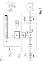
- the figure represents a system 200 provided by the present invention, the system comprising a machine 100 powered by a variable frequency drive 210, the machine being monitored by machine monitoring device 10, machine monitoring device 10 comprising as subunits, communications link 20 and controller 30.
- the machine monitoring device 10 is operationally coupled to the machine 100 via a power transmission cable 222 linking the machine to the associated variable frequency drive 210.
- the machine monitoring device 10 is configured to interface with the machine 100 via electrical interface 28a and the variable frequency drive 210 via electrical interface 28b.
- the machine monitoring device 10 also serves as the electrical connection between the variable frequency drive and allied components on the one hand, and the machine driven by the variable frequency drive on the other.
- Machine monitoring device 10 functions essentially as described in the discussion of Fig. 1 and elsewhere herein.
- a high frequency electric probe signal 22 interrogates the machine 100 via power transmission cable 222 via a capacitive or inductive coupling unit 25 attached to the power transmission cable.
- the probe signal 22 is generated by processor-microcontroller unit 38 working in tandem with switching network 27 to inject the probe signal directly into the power transmission cable.
- Blocking filter 26 inhibits the transmission of the probe signal into other components of the system, such as the variable frequency drive.
- Attenuation and/or amplification of probe signal 23a and machine sensor signals 23b are detected by voltage current sensor 24 and are transmitted to processor-microcontroller unit 38 via analog to digital converter 36.
- a library, 50 containing measured and predicted machine operating condition outputs is updated during the course of operation of the machine.
- the machine monitoring device alerts a human operator via alerting unit 40 if one or more measured or predicted machine operating condition outputs is at variance with a predetermined threshold machine operating condition output.
- a targeted machine component for example an active magnetic bearing
- a probe signal is interrogated with a probe signal via a communications link.
- Such interrogation comprises operating the machine at a first operating condition and measuring the alteration of the probe signal resulting at least in part by the interaction of the probe signal with the targeted machine component, and recording the correspondence between the alteration of the probe signal with the first operating condition.
- a given machine operating condition may at times herein be referred to as a machine component operating condition input variable.
- the alteration of the probe signal at the given machine operating condition may at times herein be referred to as the machine component operating condition output.
- one or more machine component attributes for example rotor displacement within the targeted magnetic bearing is sensed and recorded via the communications link during the operation of the machine at the first operating condition.
- machine component attributes also constitute machine operating condition outputs.
- a targeted machine component operating condition input variable for example a rotor speed, is selected for which a corresponding targeted machine component operating condition output is unknown.
- a predictive model is applied in which the targeted machine component operating condition input variable serves as an argument of a predicted targeted machine component operating condition output.
- the predictive model comprises at least two independent primary models, for each of which primary models at least one correspondence between a primary model targeted machine component operating condition and a corresponding primary model targeted machine component output are known; the primary models sharing or having been converted into the predictive model in which the primary models share a single common basis.
- a library of predicted targeted machine component operating condition outputs is updated.
- a human operator is alerted if a predicted targeted machine component operating condition output is at variance with a predetermined threshold targeted machine component operating condition output.
- the figure represents a frequency response 400 of a machine to a probe signal according to one or more embodiments of the present invention and shows the magnitude 404 of the probe signal as a function of the frequency 403 of the probe signal.
- a machine first frequency response function (FRF) 401 is obtained at a first rotor speed ⁇ 1 and a second frequency response function 402 of the same machine is obtained at a second rotor speed ⁇ 2 .
- the probe signal at times herein referred to as an excitation signal, may be applied to one or more machine components such as a stator coil or a magnetic bearing at different rotor speeds.
- the illustrated frequency response functions 401 and 402 are obtained by applying the probe signal at rotor speed ⁇ 1 and subsequently applying the same probe signal at rotor speed ⁇ 2 and measuring the machine-induced alteration of the probe signal embodied in plots 401 and 402.
- rotor speeds ⁇ 1 and ⁇ 2 represent machine operating condition input variables
- frequency responses 401 and 402 represent machine operating condition outputs and may serve as components, together with sensed machine attributes such as vibrational levels, of independent primary models with which to create a predictive model capable of predicting machine operating condition outputs in response to the probe signal under untested machine operating conditions, rotor speeds ⁇ 3 - ⁇ n .
- the machine monitoring device computes the predictive model by constructing a common basis for the available primary models of machine behavior.
- a common basis or coordinates set for all available models is then obtained. Since the at least two of the primary models were obtained from experimental data gathered under different machine operating conditions (e.g. different rotor speeds), there is no guarantee that the two state space representations use the same set of coordinates for each state.
- the inputs and outputs are clearly defined since they correspond to physical signals (e.g.
- the machine monitoring device controller computes a common basis for the primary models by (i) choosing an input/output pair of the multiple-input multiple-output system, (ii) computing the poles and zeros of this single-input single-output (SISO) system and sorting these poles and zeros in the same order for all systems, and (iii) dividing this SISO system into a combination of first order and second order subsystems and applying a canonical transformation to each subsystem. This representation is unique provided the sorting in step is done properly. Once all available systems have been transformed, an interpolation or extrapolation can be done directly on the mathematical models.
- SISO single-input single-output
- electric current I 102 is provided via cable 222 to power a machine 100 while sensor 104 senses and transmits the vibrational level 34 (Y 1 to Y n ) of the machine at machine speeds X 1 to X n .
- the vibration level of the machine depends on the rotor speed X (32) of the machine which in turn depends on the input current 102.
- the commissioning of the machine shown in Fig. 5 would be carried out as follows. First, the vibrational level of the machine at 0 rpm is measured. If the safe vibrational level is not exceeded, the rotor speed of the machine is increased to 100 rpm and the vibration level is again be measured. If the safe vibrational level is not exceeded, the rotor speed of the machine would be increased to 200 rpm and the vibration level would again be measured. This incremental approach would be repeated until the maximum nominal operating speed (1000 rpm) is reached.
- the present invention illustrated by the non-limiting embodiment shown in Fig. 6 , provides solutions to these and other challenges.
- primary models of the machine in operation are obtained at 0 rpm and at 100 rpm, speeds at which the machine vibrations are expected to be very low and therefore safe operation is highly probable.
- the primary models either initially share a common basis or are converted into primary models sharing a common basis before being incorporated into a predictive model which can be used to obtain a prediction of the vibration levels for any speed in the range 0 rpm to 1000rpm.
- the present invention requires only measurements of two machine operating condition outputs; the frequency response function of a probe signal reference and the measured vibrational level at 0 rpm and 100 rpm.
- the machine is probed with a probe signal R (22) (in this example an auxiliary current) to interrogate and study the machine response.
- the probe signal is injected into power supply cable 222 where it is added to machine input current 102.
- the present invention requires only one probe signal be used to record frequency response functions for the machine at two speeds 0 rpm and 100 rpm.
- the attenuated and/or amplified probe signal 23b is detected at machine sensor 122 and relayed via a communications link 20 to a machine monitoring device controller 30.
- the predictive model can be represented as well by the family of frequency response functions 800 shown in Fig.
- each curve illustrates machine vibration output at a given speed within the range 0 rpm to 100 rpm.
- Y 1 (t), Y 2 (t), G 1 (s) and G 2 (s) constitute the primary models used to generate the predictive model.
Landscapes
- Engineering & Computer Science (AREA)
- Physics & Mathematics (AREA)
- General Physics & Mathematics (AREA)
- Mathematical Physics (AREA)
- Automation & Control Theory (AREA)
- Artificial Intelligence (AREA)
- Evolutionary Computation (AREA)
- Software Systems (AREA)
- Data Mining & Analysis (AREA)
- Theoretical Computer Science (AREA)
- Pure & Applied Mathematics (AREA)
- Computational Mathematics (AREA)
- Mathematical Analysis (AREA)
- Mathematical Optimization (AREA)
- Operations Research (AREA)
- Health & Medical Sciences (AREA)
- Algebra (AREA)
- Computer Vision & Pattern Recognition (AREA)
- Databases & Information Systems (AREA)
- General Engineering & Computer Science (AREA)
- Medical Informatics (AREA)
- Testing And Monitoring For Control Systems (AREA)
Abstract
Description
- This invention relates to devices useful for monitoring machine performance. In particular, the present invention relates to machine monitoring devices which rely in part on prediction of machine responses to changes in machine operating conditions.
- Equipment monitoring devices are of fundamental importance to modem engineering. Increasingly, data taken from machines in operation is compared with models generated from earlier data taken from the same or similar machines to assure compliance with design specifications and to predict future performance. In large, complex machines such predictive models tend to be based on data gathered through painstaking experimentation during which machine operating conditions are systematically varied while machine outputs are recorded. Particularly when a machine is initially deployed, there may be little or no historical data available with which to predict machine responses to changes in machine operating conditions. A significant amount of historical data may be required in order to establish models useful in machine monitoring devices.
- There is a need for machine monitoring devices which are capable of establishing useful predictive models with limited data, and which can alert operators to potential deviations from acceptable machine performance based on outputs of the predictive models.
- In one embodiment, the present invention provides a machine monitoring device, the device comprising: (a) a communications link to interrogate a machine with a probe signal and receive one or more measured machine operating condition outputs; and (b) a device controller for: (i) selecting a machine operating condition input variable for which a corresponding machine operating condition output is unknown; (ii) applying a predictive model in which the machine operating condition input variable serves as an argument of a predicted machine operating condition output; (iii) updating a library of predicted machine operating condition outputs; and (iv) alerting a human operator if a measured or predicted machine operating condition output is at variance with a predetermined threshold machine operating condition output; wherein the predictive model comprises at least two independent primary models, for each of which primary models at least one correspondence between a primary model machine operating condition and a corresponding primary model machine output are known; the primary models sharing a single common basis within the predictive model.
- In an alternate embodiment, the present invention provides a system comprising a machine monitoring device operationally coupled to a machine, the machine monitoring device comprising: (a) a communications link to interrogate the machine with a probe signal and receive one or more measured machine operating condition outputs; and (b) a device controller for: (i) selecting a machine operating condition input variable for which a corresponding machine operating condition output is unknown; (ii) applying a predictive model in which the machine operating condition input variable serves as an argument of a predicted machine operating condition output; (iii) updating a library of predicted machine operating condition outputs; and (iv) alerting a human operator if a measured or predicted machine operating condition output is at variance with a predetermined threshold machine operating condition output; wherein the predictive model comprises at least two independent primary models, for each of which primary models at least one correspondence between a primary model machine operating condition and a corresponding primary model machine output are known; the primary models sharing a single common basis within the predictive model.
- In yet another embodiment, the present invention provides a method of monitoring a machine with a machine monitoring device, the method comprising: (a) interrogating a targeted machine component with a probe signal via a communications link and receiving one or more measured machine operating condition outputs; and (b) selecting a targeted machine component operating condition input variable for which a corresponding targeted machine component operating condition output is unknown; (c) applying a predictive model in which the targeted machine component operating condition input variable serves as an argument of a predicted targeted machine component operating condition output; (d) updating a library of predicted targeted machine component operating condition outputs; and (e) alerting a human operator if a measured or predicted targeted machine component operating condition output exceeds a predetermined threshold targeted machine component operating condition output; wherein the predictive model comprises at least two independent primary models, for each of which primary models at least one correspondence between a primary model targeted machine component operating condition and a corresponding primary model targeted machine component output are known; the primary models sharing a single common basis within the predictive model.
- Various features, aspects, and advantages of the present invention will become better understood when the following detailed description is read with reference to the accompanying drawings in which like characters may represent like parts throughout the drawings. Unless otherwise indicated, the drawings provided herein are meant to illustrate key inventive features of the invention. These key inventive features are believed to be applicable in a wide variety of systems which comprising one or more embodiments of the invention. As such, the drawings are not meant to include all conventional features known by those of ordinary skill in the art to be required for the practice of the invention.
-
Fig. 1 illustrates a machine monitoring device provided by the present invention. -
Fig. 2 illustrates a system provided by the present invention. -
Fig. 3 illustrates a method provided by the present invention. -
Fig. 4 illustrates frequency responses of a machine to a probe signal according to one or more embodiments of the present invention. -
Fig. 5 illustrates one or more aspects of the present invention. -
Fig. 6 illustrates one or more aspects of the present invention. -
Fig. 7 illustrates frequency responses of a machine to a probe signal under two different machine operating conditions. -
Fig. 8 illustrates a graphical representation of a predictive model according to one or more embodiments of the present invention. - In the following specification and the claims, which follow, reference will be made to a number of terms, which shall be defined to have the following meanings.
- The singular forms "a", "an", and "the" include plural referents unless the context clearly dictates otherwise.
- "Optional" or "optionally" means that the subsequently described event or circumstance may or may not occur, and that the description includes instances where the event occurs and instances where it does not.
- Approximating language, as used herein throughout the specification and claims, may be applied to modify any quantitative representation that could permissibly vary without resulting in a change in the basic function to which it is related. Accordingly, a value modified by a term or terms, such as "about" and "substantially", are not to be limited to the precise value specified. In at least some instances, the approximating language may correspond to the precision of an instrument for measuring the value. Here and throughout the specification and claims, range limitations may be combined and/or interchanged, such ranges are identified and include all the sub-ranges contained therein unless context or language indicates otherwise.
- In one or more embodiments the present invention provides a machine monitoring device useful for evaluating machine performance. The monitoring device is capable of interrogating the machine with one or more probe signals and receiving one or more measured machine operating condition outputs. In one or more embodiments, the probe signal interrogates the machine and generates a machine frequency response function (FRF) for a given machine operating condition, such as a given machine rotor speed. In addition, one or more sensors deployed in and/or around the machine may provide machine operating condition output data such as vibrational level, temperature, pressure, and displacement. Such machine operating condition output data may in turn be sent to the machine monitoring device controller via the communications link. In one or more embodiments, changes in the probe signal appear as changes in the frequency of onset of probe signal attenuation and/or amplification in response to a change in a machine operating condition. These changes are the result of machine-probe signal interactions and may be measured and correlated with one or more machine operating condition outputs. The extent to which the probe signal is altered, and the nature of such alteration may be a function of the state of the machine during interrogation by the probe signal. Thus, the machine may be in a stationary or an active operational (non-stationary) state. In either case, the probe signal may be sensitive to external parameters such as ambient temperature, ambient humidity, barometric pressure which also constitute elements of the machine state. Primarily, however, the probe signal will be sensitive to machine operational parameters such as machine component rotational speed, machine component temperature, machine component displacement, and the like.
- Those of ordinary skill in the art will appreciate that a variety of probe signals are available for use in machine interrogation. These include electric signals, optical signals, acoustic signals, radiofrequency signals, and combinations thereof. In one or more embodiments, the probe signal is a high frequency electrical signal. In one or more alternate embodiments, the probe signal is an optical signal. In one or more embodiments, the probe signal is an orthogonal random phase multi-sine electrical signal such as are known in the art.
- As noted, the machine monitoring device comprises a communications link which permits the device to interrogate one or more machine components with a probe signal, to receive measured machine operating condition outputs, and to detect changes in probe signal characteristics such as its attenuation as a function of frequency under different machine operating conditions. Machine operating condition outputs such as machine component vibrational level, machine component temperature and pressure will be dependent on the state of the machine at the time of its interrogation. It is useful to think of the machine state in terms of individual parameters such as rotational speed, or sets of parameters such as ambient temperature and rotational speed. Such individual parameters and sets of parameters are at times herein referred to as machine operating condition input variables. It follows that machine operating condition outputs reflect a machine state characterized at least in part by the individual parameter or set of parameters being considered.
- In one or more embodiments, the communications link is configured such that a probe signal having known voltage and frequency characteristics may be injected into a machine power supply at a frequency greater than the fundamental electrical frequency (and its low order harmonics) powering the machine. This creates a high frequency current signal which may be measured as part of a voltage and current sensor interfaced with the power line. Such signal injection components are described in detail in co-pending
United States patent application serial number 14/663691 filed March 20, 2015 - In one aspect, an advantage offered by the machine monitoring device provided by the present invention lies in its ability to predict the machine operating condition output for which no correlation yet exists with a corresponding machine operating condition input variable. For example, a machine operating condition output such as the vibrational state of a machine component of an untested machine state may be predicted in advance of testing at such machine state, or in many cases in lieu of such testing. The predictive power of the machine monitoring device thus enables the more rapid deployment and commissioning of complex machines such as compressors and turbines, and can also alert operators to potential problems when a measured or predicted machine operating condition output is at variance with a predetermined threshold machine operating condition output.
- Thus in one or more embodiments, a device controller may be programmed to select a machine operating condition input variable, for example a rotor speed, for which a corresponding machine operating condition output is unknown. The controller applies a predictive model of the machine's performance wherein the input variable, for example rotor speed, serves as an argument of a predicted machine operating condition output, for example the expected vibrational level of a particular machine component at the given rotor speed. The controller then updates a library of predicted machine operating condition outputs. The controller is similarly configured to update a library of measured machine operating condition outputs which may be used to update the predictive model. Finally, the device controller is programmed to alert a human operator if a measured or predicted machine operating condition output is at variance with a predetermined threshold machine operating condition output.
- The predictive model, described in detail herein, relies upon at least two independent primary models. Each of the primary models includes at least one known correspondence between a primary model machine operating condition and a corresponding primary model machine output. Such correspondences are illustrated by frequency response plots 401 and 402 shown in
Fig. 4 , at times herein referred to as frequency response functions (FRFs).FRFs - In one or more embodiments, primary model machine outputs and the predicted machine operating condition output include one or more of a machine temperature, a machine pressure, a machine vibrational characteristic, a machine rotational speed, a machine translational speed, a machine acceleration, a machine force, a machine torque, a machine power input variable, time of operation, machine age, a machine weight characteristic, a machine geometry characteristic, and a characteristic of matter being processed by the machine.
- The predictive model is created by first creating and combining at least two independent primary models. The independent primary models can be created using known modeling tools such as MATLAB using a limited number of correspondences between a machine operating condition and a corresponding machine output.
- Turning now to the figures,
Fig. 1 illustrates amachine monitoring device 10 provided by the present invention. In the embodiment shown, acommunications link 20 transmits aprobe signal 22 to amachine 100 being monitored at a limited number of machine operating conditions and receivesdata 23 from the machine. In one or more embodiments, the data is detected as the attenuation and/oramplification 23a of the probe signal as a function of frequency which is used to generate a frequency response function (FRF) for a given machine operating condition. In addition,machine sensor data 23b is received through the communications link during this limited operation of the machine. Thus, during a limited set of machine operating conditions designated input variables, for example rotor speeds X1, X2, and X3, and the corresponding machine operating condition outputs Y1, Y2, and Y3 are recorded by the machine monitoring device. Again, these operating condition outputs include both the machinefrequency response behavior 23a andmachine sensor data 23b. The limited number of such X to Y correspondences are used in combination with the predictive model discussed above to predict machine operating condition outputs (Yn+1, Yn, Yn-1 ...) for which such correspondences with machine operating input variables (Xn+1, Xn, Xn-1 ...) are unknown. In the embodiment shown,device controller 30 has access to a range of machine operating inputs X1 - Xn+1. The device controller selects a machine operating inputvariable X n 32 for which a corresponding machine operatingcondition output Y n 34 is unknown and predicts such output. Alibrary 50 containing predicted machine operating condition outputs is then updated. The machine monitoring device alerts a human operator via alertingunit 40 if the machine operatingcondition output Y n 34 is at variance with a predetermined threshold machine operating condition output. In one or more embodiments, this is carried out by comparing the machineoperating condition output 34 with a predetermined acceptable range of machine operating condition outputs. In one or more embodiments, the alertingunit 40 comprises a control center computer, a portable electronic device, an optical warning device, an audible warning device or a combination of two or more of the foregoing. - In one or more embodiments, the machine operating condition input variable Xn is extrapolative relative to at least two X to Y correspondences between the primary model machine operating conditions and the corresponding primary model machine outputs. In one or more alternate embodiments, the machine operating condition input variable Xn is interpolative relative to at least two X to Y correspondences between the primary model machine operating conditions and the corresponding primary model machine outputs.
- Referring to
Fig. 2 , the figure represents asystem 200 provided by the present invention, the system comprising amachine 100 powered by avariable frequency drive 210, the machine being monitored bymachine monitoring device 10,machine monitoring device 10 comprising as subunits, communications link 20 andcontroller 30. In the embodiment shown, themachine monitoring device 10 is operationally coupled to themachine 100 via apower transmission cable 222 linking the machine to the associatedvariable frequency drive 210. Themachine monitoring device 10 is configured to interface with themachine 100 viaelectrical interface 28a and thevariable frequency drive 210 viaelectrical interface 28b. As such, themachine monitoring device 10 also serves as the electrical connection between the variable frequency drive and allied components on the one hand, and the machine driven by the variable frequency drive on the other.Machine monitoring device 10 functions essentially as described in the discussion ofFig. 1 and elsewhere herein. In the embodiment shown, a high frequencyelectric probe signal 22 interrogates themachine 100 viapower transmission cable 222 via a capacitive orinductive coupling unit 25 attached to the power transmission cable. Theprobe signal 22 is generated by processor-microcontroller unit 38 working in tandem with switchingnetwork 27 to inject the probe signal directly into the power transmission cable. Blockingfilter 26 inhibits the transmission of the probe signal into other components of the system, such as the variable frequency drive. Attenuation and/or amplification ofprobe signal 23a and machine sensor signals 23b are detected by voltagecurrent sensor 24 and are transmitted to processor-microcontroller unit 38 via analog todigital converter 36. As discussed in reference toFig. 1 , a library, 50, containing measured and predicted machine operating condition outputs is updated during the course of operation of the machine. The machine monitoring device alerts a human operator via alertingunit 40 if one or more measured or predicted machine operating condition outputs is at variance with a predetermined threshold machine operating condition output. - Referring to
Fig. 3 , the figure illustrates amethod 300 of monitoring a machine according to one or more embodiments of the present invention. In afirst method step 301, a targeted machine component, for example an active magnetic bearing, is interrogated with a probe signal via a communications link. Such interrogation comprises operating the machine at a first operating condition and measuring the alteration of the probe signal resulting at least in part by the interaction of the probe signal with the targeted machine component, and recording the correspondence between the alteration of the probe signal with the first operating condition. A given machine operating condition may at times herein be referred to as a machine component operating condition input variable. Similarly, the alteration of the probe signal at the given machine operating condition may at times herein be referred to as the machine component operating condition output. In addition to recording the frequency response behavior of the probe signal, one or more machine component attributes, for example rotor displacement within the targeted magnetic bearing is sensed and recorded via the communications link during the operation of the machine at the first operating condition. Such machine component attributes also constitute machine operating condition outputs. In a second method step, 302, a targeted machine component operating condition input variable, for example a rotor speed, is selected for which a corresponding targeted machine component operating condition output is unknown. In a third method step, 303, a predictive model is applied in which the targeted machine component operating condition input variable serves as an argument of a predicted targeted machine component operating condition output. The predictive model comprises at least two independent primary models, for each of which primary models at least one correspondence between a primary model targeted machine component operating condition and a corresponding primary model targeted machine component output are known; the primary models sharing or having been converted into the predictive model in which the primary models share a single common basis. In a fourth method step, 304, a library of predicted targeted machine component operating condition outputs is updated. In a fifth method step, 305, a human operator is alerted if a predicted targeted machine component operating condition output is at variance with a predetermined threshold targeted machine component operating condition output. - Referring to
Fig. 4 , the figure represents afrequency response 400 of a machine to a probe signal according to one or more embodiments of the present invention and shows themagnitude 404 of the probe signal as a function of thefrequency 403 of the probe signal. In the embodiment shown, a machine first frequency response function (FRF) 401 is obtained at a first rotor speed Ω1 and a secondfrequency response function 402 of the same machine is obtained at a second rotor speed Ω2. For example, the probe signal, at times herein referred to as an excitation signal, may be applied to one or more machine components such as a stator coil or a magnetic bearing at different rotor speeds. The illustrated frequency response functions 401 and 402 are obtained by applying the probe signal at rotor speed Ω1 and subsequently applying the same probe signal at rotor speed Ω2 and measuring the machine-induced alteration of the probe signal embodied inplots frequency responses - In one or more embodiments, the machine monitoring device computes the predictive model by constructing a common basis for the available primary models of machine behavior. In order to draw parallelisms and establish connections between the two (or more) available primary models, it is first necessary to ensure that the coordinates of both models coincide, that is, state vector x in the state space description corresponds to the same set of variables in both models. A common basis or coordinates set for all available models is then obtained. Since the at least two of the primary models were obtained from experimental data gathered under different machine operating conditions (e.g. different rotor speeds), there is no guarantee that the two state space representations use the same set of coordinates for each state. The inputs and outputs are clearly defined since they correspond to physical signals (e.g. vibrations and currents in the Example herein), but the same cannot be guaranteed for the states. In one or more embodiments, the machine monitoring device controller computes a common basis for the primary models by (i) choosing an input/output pair of the multiple-input multiple-output system, (ii) computing the poles and zeros of this single-input single-output (SISO) system and sorting these poles and zeros in the same order for all systems, and (iii) dividing this SISO system into a combination of first order and second order subsystems and applying a canonical transformation to each subsystem. This representation is unique provided the sorting in step is done properly. Once all available systems have been transformed, an interpolation or extrapolation can be done directly on the mathematical models.
- Additional guidance on methodologies used herein is available in Blom R. S., Delft, 2011, 244 pages, ISBN: 9789491104077 and J. De Caigny et al. Proceedings of ISMA2008 which are incorporated by reference herein in their entirety.
- We consider here the deployment and commissioning of a machine whose behavior depends on the rotor speed having a nominal operating range of 0 to 1000rpm. In this example, a requirement for safe operation is that the vibrations in the machine do not surpass 3 centimeter per second squared (3cm/s2). The magnitude of machine vibrations increases as the rotor speed of the machine increases. In order to commission this machine, it is necessary to demonstrate that vibrations will not exceed the 3cm/s2 safety requirement. A
comparative system 200 in normal operation is depicted inFig. 5 . wherein electric current I 102 is provided viacable 222 to power amachine 100 whilesensor 104 senses and transmits the vibrational level 34 (Y1 to Yn) of the machine at machine speeds X1 to Xn. Again, the vibration level of the machine depends on the rotor speed X (32) of the machine which in turn depends on the input current 102. - The commissioning of the machine shown in
Fig. 5 would be carried out as follows. First, the vibrational level of the machine at 0 rpm is measured. If the safe vibrational level is not exceeded, the rotor speed of the machine is increased to 100 rpm and the vibration level is again be measured. If the safe vibrational level is not exceeded, the rotor speed of the machine would be increased to 200 rpm and the vibration level would again be measured. This incremental approach would be repeated until the maximum nominal operating speed (1000 rpm) is reached. - Such conventional commissioning procedures are inherently limited. First, it is time consuming to repeat measurements at incrementally increasing speeds across the desired operational range. Second, because the true vibrational behavior of the machine during operation is unknown until the machine is put into operation, critical threshold vibrational limits may be exceeded during initial testing. Under various circumstances, including unforeseen and undetected damage done to the machine during transport, there is a risk that a machine will not function properly even within its nominal range of operating conditions. Under such circumstances, as the speed is increased within the nominal operating range, the machine vibrational level could exceed a predetermined threshold operating vibrational level, 3cm/s2 in this example, and be damaged. In large high kinetic energy rotating machines such excursions can be catastrophic.
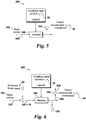
- The present invention, illustrated by the non-limiting embodiment shown in
Fig. 6 , provides solutions to these and other challenges. Thus, primary models of the machine in operation are obtained at 0 rpm and at 100 rpm, speeds at which the machine vibrations are expected to be very low and therefore safe operation is highly probable. The primary models either initially share a common basis or are converted into primary models sharing a common basis before being incorporated into a predictive model which can be used to obtain a prediction of the vibration levels for any speed in therange 0 rpm to 1000rpm. - The present invention requires only measurements of two machine operating condition outputs; the frequency response function of a probe signal reference and the measured vibrational level at 0 rpm and 100 rpm. To obtain a predictive model in this example, the machine is probed with a probe signal R (22) (in this example an auxiliary current) to interrogate and study the machine response. The probe signal is injected into
power supply cable 222 where it is added to machine input current 102. The present invention requires only one probe signal be used to record frequency response functions for the machine at twospeeds 0 rpm and 100 rpm. In the embodiment shown, the attenuated and/or amplifiedprobe signal 23b is detected atmachine sensor 122 and relayed via acommunications link 20 to a machinemonitoring device controller 30. These frequency response functions G1 (701) and G2 (702) are shown inFig. 7 . Because one of the two speeds is 0 rpm, a single input current corresponding to a machine speed of 100 rpm may be used. At 0 rpm the same input current required to produce a machine speed of 100 rpm is applied, but the machine is mechanically locked in a stationary state. Machine vibration levels Y1 and Y2 (34) corresponding tomachine speeds 0 rpm and 100 rpm are measured via a sensor 104 (Fig. 6 ). The vibration levels Y1 and Y2 are a function of the machine operating condition input variable (speed), theprobe signal 22 magnitude (R) and the input current 102 (I). In this example theprobe signal 22 is a sine wave and the input current 102 is held constant at two amperes (I(t) = 2 amperes). The magnitude R ofprobe signal 22 varies with time and can be expressed mathematically as
- The measured vibration levels also vary with time at constant speed. Vibrational data is collected from
sensor 104. In stationary state (0 rpm) the vibrational level of the machine can be expressed
- Similarly, the measured vibration level when the machine is rotating at 100rpm may be expressed as

- Next, the frequency response functions G1 (701) and G2 (702) (
Fig. 7 ) can be parametrized using art known parametrization techniques and expressed mathematically as

Fig. 8 wherein each curve illustrates machine vibration output at a given speed within therange 0 rpm to 100 rpm. Those of ordinary skill in the art will understand that, in the example just given Y1(t), Y2(t), G1(s) and G2(s) constitute the primary models used to generate the predictive model. - The foregoing examples are merely illustrative, serving to illustrate only some of the features of the invention. The appended claims are intended to claim the invention as broadly as it has been conceived and the examples herein presented are illustrative of selected embodiments from a manifold of all possible embodiments. Accordingly, it is Applicants' intention that the appended claims are not to be limited by the choice of examples utilized to illustrate features of the present invention. As used in the claims, the word "comprises" and its grammatical variants logically also subtend and include phrases of varying and differing extent such as for example, but not limited thereto, "consisting essentially of" and "consisting of." Where necessary, ranges have been supplied, those ranges are inclusive of all sub-ranges there between. It is to be expected that variations in these ranges will suggest themselves to a practitioner having ordinary skill in the art and where not already dedicated to the public, those variations should where possible be construed to be covered by the appended claims. It is also anticipated that advances in science and technology will make equivalents and substitutions possible that are not now contemplated by reason of the imprecision of language and these variations should also be construed where possible to be covered by the appended claims.
- Various aspects and embodiments of the present invention are defined by the following numbered clause:
- 1. A machine monitoring device, the device comprising:
- (a) a communications link to interrogate the machine with a probe signal and receive one or more measured machine operating condition outputs; and
- (b) a device controller for:
- (i) selecting a machine operating condition input variable for which a corresponding machine operating condition output is unknown;
- (ii) applying a predictive model in which the machine operating condition input variable serves as an argument of a predicted machine operating condition output;
- (iii) updating a library of predicted machine operating condition outputs; and
- (iv) alerting a human operator if a measured or predicted machine operating condition output is at variance with a predetermined threshold machine operating condition output;
- 2. The machine monitoring device according to
clause 1, wherein the at least two independent primary models do not share a common basis prior to being converted into the predictive model. - 3. The machine monitoring device according to
clause 1 orclause 2, wherein the at least two independent primary models share a common basis prior to being converted into the predictive model. - 4. The machine monitoring device according to any preceding clause, wherein the primary model machine outputs and the predicted machine operating condition output include one or more of a machine temperature, a machine pressure, a machine vibrational characteristic, a machine rotational speed, a machine translational speed, a machine acceleration, a machine force, a machine torque, a machine power input variable, time of operation, machine age, a machine weight characteristic, a machine geometry characteristic, a characteristic of matter being processed by the machine.
- 5. The machine monitoring device according to any preceding clause, wherein the primary model machine outputs and the predicted machine operating condition output includes a machine component rotational speed.
- 6. The machine monitoring device according to any preceding clause, wherein the primary model machine outputs reflect the machine in non-stationary states.
- 7. The machine monitoring device according to any preceding clause, wherein the machine is selected from the group consisting of turbines, wind turbines, compressors, turboexpanders, motors, and pumps.
- 8. The machine monitoring device according to any preceding clause, wherein the probe signal is a high frequency electrical signal.
- 9. The machine monitoring device according to any preceding clause, wherein the probe signal is an optical signal.
- 10. The machine monitoring device according to any preceding clause, wherein the machine operating condition input variable is extrapolative relative to at least two correspondences between the primary model machine operating condition and the corresponding primary model machine output.
- 11. The machine monitoring device according to any preceding clause, wherein the machine operating condition input variable is interpolative relative to at least two correspondences between the primary model machine operating condition and the corresponding primary model machine output.
- 12. A system comprising:
- a machine monitoring device operationally coupled to a machine, the machine monitoring device comprising:
- (a) a communications link to interrogate the machine with a probe signal and receive one or more measured machine operating condition outputs; and
- (b) a device controller for:
- (i) selecting a machine operating condition input variable for which a corresponding machine operating condition output is unknown;
- (ii) applying a predictive model in which the machine operating condition input variable serves as an argument of a predicted machine operating condition output;
- (iii) updating a library of predicted machine operating condition outputs; and
- (iv) alerting a human operator if a measured or predicted machine operating condition output is at variance with a predetermined threshold machine operating condition output;
- a machine monitoring device operationally coupled to a machine, the machine monitoring device comprising:
- 13. The system according to any preceding clause wherein the at least two independent primary models do not share a common basis prior to being converted into the predictive model.
- 14. The system according to any preceding clause, wherein the machine operating condition input variable is selected from the group consisting of a machine temperature, a machine pressure, a machine vibrational characteristic, a machine rotational speed, a machine translational speed, a machine acceleration, a machine force, a machine torque, a machine power input variable, time of operation, machine age, a machine weight characteristic, a machine geometry characteristic, a characteristic of matter being processed by the machine.
- 15. The system according to any preceding clause, wherein the machine is selected from the group consisting of turbines, wind turbines, compressors, turboexpanders, motors, and pumps.
- 16. The system according to any preceding clause, wherein the machine operating condition input variable is extrapolative relative to at least two correspondences between the primary model machine operating condition and the corresponding primary model machine output.
- 17. The system according to any preceding clause, wherein the machine operating condition input variable is interpolative relative to at least two correspondences between the primary model machine operating condition and the corresponding primary model machine output.
- 18. A method of monitoring a machine with a machine monitoring device, the method comprising:
- (a) interrogating a targeted machine component with a probe signal via a communications link and receiving one or more measured machine operating condition outputs;
- (b) selecting a targeted machine component operating condition input variable for which a corresponding targeted machine component operating condition output is unknown;
- (c) applying a predictive model in which the targeted machine component operating condition input variable serves as an argument of a predicted targeted machine component operating condition output;
- (d) updating a library of predicted targeted machine component operating condition outputs; and
- (e) alerting a human operator if a measured or predicted targeted machine component operating condition output is at variance with a predetermined threshold targeted machine component operating condition output;
- 19. The method according to any preceding clause, wherein the targeted machine component is a rotor.
- 20. The method according to any preceding clause, wherein the targeted machine component is a rotor of a permanent magnet motor.
- 21. The method according to any preceding clause, wherein the targeted machine component is a bearing.
- 22. The rotary machine monitoring device according to any preceding clause, wherein the targeted machine component is a magnetic bearing.
Claims (15)
- A machine monitoring device, the device comprising:(a) a communications link to interrogate the machine with a probe signal and receive one or more measured machine operating condition outputs; and(b) a device controller for:wherein the predictive model comprises at least two independent primary models, for each of which primary models at least one correspondence between a primary model machine operating condition and a corresponding primary model machine output are known; the primary models sharing or having been converted into the predictive model in which the primary models share a single common basis.(i) selecting a machine operating condition input variable for which a corresponding machine operating condition output is unknown;(ii) applying a predictive model in which the machine operating condition input variable serves as an argument of a predicted machine operating condition output;(iii) updating a library of predicted machine operating condition outputs; and(iv) alerting a human operator if a measured or predicted machine operating condition output is at variance with a predetermined threshold machine operating condition output;
- The machine monitoring device according to claim 1, wherein the at least two independent primary models do not share a common basis prior to being converted into the predictive model.
- The machine monitoring device according to claim 1 or claim 2, wherein the at least two independent primary models share a common basis prior to being converted into the predictive model.
- The machine monitoring device according to any preceding claim, wherein the primary model machine outputs and the predicted machine operating condition output include one or more of a machine temperature, a machine pressure, a machine vibrational characteristic, a machine rotational speed, a machine translational speed, a machine acceleration, a machine force, a machine torque, a machine power input variable, time of operation, machine age, a machine weight characteristic, a machine geometry characteristic, a characteristic of matter being processed by the machine.
- The machine monitoring device according to any preceding claim, wherein the primary model machine outputs and the predicted machine operating condition output includes a machine component rotational speed.
- The machine monitoring device according to any preceding claim, wherein the primary model machine outputs reflect the machine in non-stationary states.
- The machine monitoring device according to any preceding claim, wherein the machine is selected from the group consisting of turbines, wind turbines, compressors, turboexpanders, motors, and pumps.
- The machine monitoring device according to any preceding claim, wherein the probe signal is a high frequency electrical signal.
- The machine monitoring device according to any preceding claim, wherein the probe signal is an optical signal.
- The machine monitoring device according to any preceding claim, wherein the machine operating condition input variable is extrapolative relative to at least two correspondences between the primary model machine operating condition and the corresponding primary model machine output.
- The machine monitoring device according to any preceding claim, wherein the machine operating condition input variable is interpolative relative to at least two correspondences between the primary model machine operating condition and the corresponding primary model machine output.
- A system comprising:a machine monitoring device according to any preceding claim, operationally coupled to a machine.
- A method of monitoring a machine with a machine monitoring device, the method comprising:(a) interrogating a targeted machine component with a probe signal via a communications link and receiving one or more measured machine operating condition outputs;(b) selecting a targeted machine component operating condition input variable for which a corresponding targeted machine component operating condition output is unknown;(c) applying a predictive model in which the targeted machine component operating condition input variable serves as an argument of a predicted targeted machine component operating condition output;(d) updating a library of predicted targeted machine component operating condition outputs; and(e) alerting a human operator if a measured or predicted targeted machine component operating condition output is at variance with a predetermined threshold targeted machine component operating condition output;wherein the predictive model comprises at least two independent primary models, for each of which primary models at least one correspondence between a primary model targeted machine component operating condition and a corresponding primary model targeted machine component output are known; the primary models sharing or having been converted into the predictive model in which the primary models share a single common basis.
- The method according to claim 13, wherein the targeted machine component is a rotor.
- The method according to claim 13, wherein the targeted machine component is a rotor of a permanent magnet motor.
Applications Claiming Priority (1)
| Application Number | Priority Date | Filing Date | Title |
|---|---|---|---|
| US15/188,137 US10444714B2 (en) | 2016-06-21 | 2016-06-21 | Machine monitoring device |
Publications (2)
| Publication Number | Publication Date |
|---|---|
| EP3260944A1 true EP3260944A1 (en) | 2017-12-27 |
| EP3260944B1 EP3260944B1 (en) | 2020-11-04 |
Family
ID=59298165
Family Applications (1)
| Application Number | Title | Priority Date | Filing Date |
|---|---|---|---|
| EP17176585.2A Active EP3260944B1 (en) | 2016-06-21 | 2017-06-19 | Device and method for machine monitoring |
Country Status (3)
| Country | Link |
|---|---|
| US (1) | US10444714B2 (en) |
| EP (1) | EP3260944B1 (en) |
| CA (1) | CA2969965C (en) |
Cited By (1)
| Publication number | Priority date | Publication date | Assignee | Title |
|---|---|---|---|---|
| EP3537352A1 (en) * | 2018-03-08 | 2019-09-11 | General Electric Company | Analytics |
Citations (3)
| Publication number | Priority date | Publication date | Assignee | Title |
|---|---|---|---|---|
| EP2149824A2 (en) * | 2008-07-29 | 2010-02-03 | General Electric Company | Methods and systems for estimating operating parameters of an engine |
| US20120029892A1 (en) * | 2011-05-19 | 2012-02-02 | Matthias Thulke | Condition monitoring of windturbines |
| EP2690513A1 (en) * | 2012-07-24 | 2014-01-29 | Siemens Aktiengesellschaft | Condition monitoring for a machine, in particular a production machine or machine tool |
Family Cites Families (11)
| Publication number | Priority date | Publication date | Assignee | Title |
|---|---|---|---|---|
| GB9217761D0 (en) | 1992-08-21 | 1992-10-07 | British Tech Group | Method of and apparatus for determining a rotor displacement parameter |
| JP4293695B2 (en) | 1999-12-03 | 2009-07-08 | 株式会社荏原製作所 | Magnetic bearing control device |
| US20050193739A1 (en) * | 2004-03-02 | 2005-09-08 | General Electric Company | Model-based control systems and methods for gas turbine engines |
| WO2006120547A1 (en) | 2005-05-11 | 2006-11-16 | Toyota Jidosha Kabushiki Kaisha | Rotary electric device drive unit including the same |
| EP1895180A2 (en) | 2006-08-30 | 2008-03-05 | Ebara Corporation | Magnetic bearing device, rotating system therewith and method of identification of the model of the main unit in a rotating system |
| JP5197610B2 (en) * | 2006-09-28 | 2013-05-15 | フィッシャー−ローズマウント システムズ,インコーポレイテッド | Prevention of abnormal conditions in heat exchangers |
| DE102009028582A1 (en) | 2009-08-17 | 2011-02-24 | Robert Bosch Gmbh | Electronically commutated electric motor with a rotor position prediction and an interpolation and method |
| GB0917634D0 (en) | 2009-10-09 | 2009-11-25 | Rolls Royce Plc | Rotor behaviour determination |
| JP5549541B2 (en) | 2010-10-28 | 2014-07-16 | ダイキン工業株式会社 | Rotor position detection method, motor control method, motor control device, and program |
| JP5850960B2 (en) | 2014-02-06 | 2016-02-03 | ファナック株式会社 | Motor control device for correcting interpolation error of position detector |
| US9595903B2 (en) | 2015-03-20 | 2017-03-14 | General Electric Company | Controller for motor |
-
2016
- 2016-06-21 US US15/188,137 patent/US10444714B2/en active Active
-
2017
- 2017-06-08 CA CA2969965A patent/CA2969965C/en active Active
- 2017-06-19 EP EP17176585.2A patent/EP3260944B1/en active Active
Patent Citations (3)
| Publication number | Priority date | Publication date | Assignee | Title |
|---|---|---|---|---|
| EP2149824A2 (en) * | 2008-07-29 | 2010-02-03 | General Electric Company | Methods and systems for estimating operating parameters of an engine |
| US20120029892A1 (en) * | 2011-05-19 | 2012-02-02 | Matthias Thulke | Condition monitoring of windturbines |
| EP2690513A1 (en) * | 2012-07-24 | 2014-01-29 | Siemens Aktiengesellschaft | Condition monitoring for a machine, in particular a production machine or machine tool |
Non-Patent Citations (2)
| Title |
|---|
| BLOM R. S., DELFT, 2011, pages 244 |
| J. DE CAIGNY ET AL., PROCEEDINGS OF ISMA, 2008 |
Cited By (1)
| Publication number | Priority date | Publication date | Assignee | Title |
|---|---|---|---|---|
| EP3537352A1 (en) * | 2018-03-08 | 2019-09-11 | General Electric Company | Analytics |
Also Published As
| Publication number | Publication date |
|---|---|
| CA2969965C (en) | 2023-03-14 |
| US10444714B2 (en) | 2019-10-15 |
| EP3260944B1 (en) | 2020-11-04 |
| CA2969965A1 (en) | 2017-12-21 |
| US20170364042A1 (en) | 2017-12-21 |
Similar Documents
| Publication | Publication Date | Title |
|---|---|---|
| Faiz et al. | Comprehensive review on inter‐turn fault indexes in permanent magnet motors | |
| Akhil Vinayak et al. | Wavelet‐based real‐time stator fault detection of inverter‐fed induction motor | |
| Seera et al. | Condition monitoring of induction motors: A review and an application of an ensemble of hybrid intelligent models | |
| EP3515040A1 (en) | Reliable cyber-threat detection in rapidly changing environments | |
| Yousefi kia et al. | Hybrid modelling of doubly fed induction generators with inter‐turn stator fault and its detection method using wavelet analysis | |
| US20070073521A1 (en) | Machinery Condition Assessment Module | |
| EP4160233B1 (en) | System, apparatus and method for monitoring faults in an electric machine | |
| Abubakar et al. | Induction motor fault detection based on multi‐sensory control and wavelet analysis | |
| WO2022087726A1 (en) | Online monitoring and compensation of stator inter-turn short circuit fault in permanent magnet synchronous machines | |
| AU2021201558B2 (en) | System and method for detecting winding faults in a generator | |
| EP3234706B1 (en) | Apparatus and methods for monitoring subsea electrical systems using adaptive models | |
| Dalla Vedova et al. | Evaluation of the correlation coefficient as a prognostic indicator for electromechanical servomechanism failures | |
| EP2135144B1 (en) | Machine condition monitoring using pattern rules | |
| Samami et al. | Novel fast and secure approach for reverse power protection in synchronous generators | |
| US10444714B2 (en) | Machine monitoring device | |
| Ali et al. | Fault modelling and detection in power generation, transmission and distribution systems | |
| US12276540B2 (en) | Rotating machine vibration monitoring process for detecting degradations within a rotating machine fitted with magnetic bearings | |
| Ahumada et al. | Modelling of reduced electromechanical interaction system for aircraft applications | |
| Woodruff et al. | Testing a 5 MW high-temperature superconducting propulsion motor | |
| Abhinandan et al. | Fault diagnosis of an induction motor through motor current signature analysis, FFT & DWT analysis | |
| KR20230129513A (en) | Method, device, and system for monitoring the condition of a motor | |
| Méndez et al. | Detection of incipient faults in three-phase motors through analysis of stator currents | |
| Harahap | Speed control of induction motor using fuzzy logic based on internet of things | |
| Pacas et al. | Methods for commissioning and identification in drives | |
| JP2021503132A (en) | Methods and equipment to protect pump assemblies from cyber attacks |
Legal Events
| Date | Code | Title | Description |
|---|---|---|---|
| PUAI | Public reference made under article 153(3) epc to a published international application that has entered the european phase |
Free format text: ORIGINAL CODE: 0009012 |
|
| STAA | Information on the status of an ep patent application or granted ep patent |
Free format text: STATUS: THE APPLICATION HAS BEEN PUBLISHED |
|
| AK | Designated contracting states |
Kind code of ref document: A1 Designated state(s): AL AT BE BG CH CY CZ DE DK EE ES FI FR GB GR HR HU IE IS IT LI LT LU LV MC MK MT NL NO PL PT RO RS SE SI SK SM TR |
|
| AX | Request for extension of the european patent |
Extension state: BA ME |
|
| STAA | Information on the status of an ep patent application or granted ep patent |
Free format text: STATUS: REQUEST FOR EXAMINATION WAS MADE |
|
| STAA | Information on the status of an ep patent application or granted ep patent |
Free format text: STATUS: EXAMINATION IS IN PROGRESS |
|
| 17P | Request for examination filed |
Effective date: 20180627 |
|
| RBV | Designated contracting states (corrected) |
Designated state(s): AL AT BE BG CH CY CZ DE DK EE ES FI FR GB GR HR HU IE IS IT LI LT LU LV MC MK MT NL NO PL PT RO RS SE SI SK SM TR |
|
| 17Q | First examination report despatched |
Effective date: 20180718 |
|
| GRAP | Despatch of communication of intention to grant a patent |
Free format text: ORIGINAL CODE: EPIDOSNIGR1 |
|
| STAA | Information on the status of an ep patent application or granted ep patent |
Free format text: STATUS: GRANT OF PATENT IS INTENDED |
|
| INTG | Intention to grant announced |
Effective date: 20200608 |
|
| GRAS | Grant fee paid |
Free format text: ORIGINAL CODE: EPIDOSNIGR3 |
|
| GRAA | (expected) grant |
Free format text: ORIGINAL CODE: 0009210 |
|
| STAA | Information on the status of an ep patent application or granted ep patent |
Free format text: STATUS: THE PATENT HAS BEEN GRANTED |
|
| AK | Designated contracting states |
Kind code of ref document: B1 Designated state(s): AL AT BE BG CH CY CZ DE DK EE ES FI FR GB GR HR HU IE IS IT LI LT LU LV MC MK MT NL NO PL PT RO RS SE SI SK SM TR |
|
| REG | Reference to a national code |
Ref country code: GB Ref legal event code: FG4D |
|
| REG | Reference to a national code |
Ref country code: CH Ref legal event code: EP |
|
| REG | Reference to a national code |
Ref country code: AT Ref legal event code: REF Ref document number: 1331614 Country of ref document: AT Kind code of ref document: T Effective date: 20201115 |
|
| REG | Reference to a national code |
Ref country code: IE Ref legal event code: FG4D |
|
| REG | Reference to a national code |
Ref country code: DE Ref legal event code: R096 Ref document number: 602017026652 Country of ref document: DE |
|
| REG | Reference to a national code |
Ref country code: NL Ref legal event code: MP Effective date: 20201104 |
|
| REG | Reference to a national code |
Ref country code: AT Ref legal event code: MK05 Ref document number: 1331614 Country of ref document: AT Kind code of ref document: T Effective date: 20201104 |
|
| REG | Reference to a national code |
Ref country code: NO Ref legal event code: T2 Effective date: 20201104 |
|
| PG25 | Lapsed in a contracting state [announced via postgrant information from national office to epo] |
Ref country code: PT Free format text: LAPSE BECAUSE OF FAILURE TO SUBMIT A TRANSLATION OF THE DESCRIPTION OR TO PAY THE FEE WITHIN THE PRESCRIBED TIME-LIMIT Effective date: 20210304 Ref country code: RS Free format text: LAPSE BECAUSE OF FAILURE TO SUBMIT A TRANSLATION OF THE DESCRIPTION OR TO PAY THE FEE WITHIN THE PRESCRIBED TIME-LIMIT Effective date: 20201104 Ref country code: GR Free format text: LAPSE BECAUSE OF FAILURE TO SUBMIT A TRANSLATION OF THE DESCRIPTION OR TO PAY THE FEE WITHIN THE PRESCRIBED TIME-LIMIT Effective date: 20210205 Ref country code: FI Free format text: LAPSE BECAUSE OF FAILURE TO SUBMIT A TRANSLATION OF THE DESCRIPTION OR TO PAY THE FEE WITHIN THE PRESCRIBED TIME-LIMIT Effective date: 20201104 |
|
| PG25 | Lapsed in a contracting state [announced via postgrant information from national office to epo] |
Ref country code: ES Free format text: LAPSE BECAUSE OF FAILURE TO SUBMIT A TRANSLATION OF THE DESCRIPTION OR TO PAY THE FEE WITHIN THE PRESCRIBED TIME-LIMIT Effective date: 20201104 Ref country code: AT Free format text: LAPSE BECAUSE OF FAILURE TO SUBMIT A TRANSLATION OF THE DESCRIPTION OR TO PAY THE FEE WITHIN THE PRESCRIBED TIME-LIMIT Effective date: 20201104 Ref country code: PL Free format text: LAPSE BECAUSE OF FAILURE TO SUBMIT A TRANSLATION OF THE DESCRIPTION OR TO PAY THE FEE WITHIN THE PRESCRIBED TIME-LIMIT Effective date: 20201104 Ref country code: IS Free format text: LAPSE BECAUSE OF FAILURE TO SUBMIT A TRANSLATION OF THE DESCRIPTION OR TO PAY THE FEE WITHIN THE PRESCRIBED TIME-LIMIT Effective date: 20210304 Ref country code: LV Free format text: LAPSE BECAUSE OF FAILURE TO SUBMIT A TRANSLATION OF THE DESCRIPTION OR TO PAY THE FEE WITHIN THE PRESCRIBED TIME-LIMIT Effective date: 20201104 Ref country code: BG Free format text: LAPSE BECAUSE OF FAILURE TO SUBMIT A TRANSLATION OF THE DESCRIPTION OR TO PAY THE FEE WITHIN THE PRESCRIBED TIME-LIMIT Effective date: 20210204 Ref country code: SE Free format text: LAPSE BECAUSE OF FAILURE TO SUBMIT A TRANSLATION OF THE DESCRIPTION OR TO PAY THE FEE WITHIN THE PRESCRIBED TIME-LIMIT Effective date: 20201104 |
|
| REG | Reference to a national code |
Ref country code: LT Ref legal event code: MG9D |
|
| PG25 | Lapsed in a contracting state [announced via postgrant information from national office to epo] |
Ref country code: HR Free format text: LAPSE BECAUSE OF FAILURE TO SUBMIT A TRANSLATION OF THE DESCRIPTION OR TO PAY THE FEE WITHIN THE PRESCRIBED TIME-LIMIT Effective date: 20201104 |
|
| PG25 | Lapsed in a contracting state [announced via postgrant information from national office to epo] |
Ref country code: SM Free format text: LAPSE BECAUSE OF FAILURE TO SUBMIT A TRANSLATION OF THE DESCRIPTION OR TO PAY THE FEE WITHIN THE PRESCRIBED TIME-LIMIT Effective date: 20201104 Ref country code: LT Free format text: LAPSE BECAUSE OF FAILURE TO SUBMIT A TRANSLATION OF THE DESCRIPTION OR TO PAY THE FEE WITHIN THE PRESCRIBED TIME-LIMIT Effective date: 20201104 Ref country code: CZ Free format text: LAPSE BECAUSE OF FAILURE TO SUBMIT A TRANSLATION OF THE DESCRIPTION OR TO PAY THE FEE WITHIN THE PRESCRIBED TIME-LIMIT Effective date: 20201104 Ref country code: EE Free format text: LAPSE BECAUSE OF FAILURE TO SUBMIT A TRANSLATION OF THE DESCRIPTION OR TO PAY THE FEE WITHIN THE PRESCRIBED TIME-LIMIT Effective date: 20201104 Ref country code: SK Free format text: LAPSE BECAUSE OF FAILURE TO SUBMIT A TRANSLATION OF THE DESCRIPTION OR TO PAY THE FEE WITHIN THE PRESCRIBED TIME-LIMIT Effective date: 20201104 Ref country code: RO Free format text: LAPSE BECAUSE OF FAILURE TO SUBMIT A TRANSLATION OF THE DESCRIPTION OR TO PAY THE FEE WITHIN THE PRESCRIBED TIME-LIMIT Effective date: 20201104 |
|
| REG | Reference to a national code |
Ref country code: DE Ref legal event code: R097 Ref document number: 602017026652 Country of ref document: DE |
|
| PG25 | Lapsed in a contracting state [announced via postgrant information from national office to epo] |
Ref country code: DK Free format text: LAPSE BECAUSE OF FAILURE TO SUBMIT A TRANSLATION OF THE DESCRIPTION OR TO PAY THE FEE WITHIN THE PRESCRIBED TIME-LIMIT Effective date: 20201104 |
|
| PLBE | No opposition filed within time limit |
Free format text: ORIGINAL CODE: 0009261 |
|
| STAA | Information on the status of an ep patent application or granted ep patent |
Free format text: STATUS: NO OPPOSITION FILED WITHIN TIME LIMIT |
|
| 26N | No opposition filed |
Effective date: 20210805 |
|
| PG25 | Lapsed in a contracting state [announced via postgrant information from national office to epo] |
Ref country code: NL Free format text: LAPSE BECAUSE OF FAILURE TO SUBMIT A TRANSLATION OF THE DESCRIPTION OR TO PAY THE FEE WITHIN THE PRESCRIBED TIME-LIMIT Effective date: 20201104 Ref country code: AL Free format text: LAPSE BECAUSE OF FAILURE TO SUBMIT A TRANSLATION OF THE DESCRIPTION OR TO PAY THE FEE WITHIN THE PRESCRIBED TIME-LIMIT Effective date: 20201104 Ref country code: IT Free format text: LAPSE BECAUSE OF FAILURE TO SUBMIT A TRANSLATION OF THE DESCRIPTION OR TO PAY THE FEE WITHIN THE PRESCRIBED TIME-LIMIT Effective date: 20201104 |
|
| PG25 | Lapsed in a contracting state [announced via postgrant information from national office to epo] |
Ref country code: SI Free format text: LAPSE BECAUSE OF FAILURE TO SUBMIT A TRANSLATION OF THE DESCRIPTION OR TO PAY THE FEE WITHIN THE PRESCRIBED TIME-LIMIT Effective date: 20201104 |
|
| PG25 | Lapsed in a contracting state [announced via postgrant information from national office to epo] |
Ref country code: MC Free format text: LAPSE BECAUSE OF FAILURE TO SUBMIT A TRANSLATION OF THE DESCRIPTION OR TO PAY THE FEE WITHIN THE PRESCRIBED TIME-LIMIT Effective date: 20201104 |
|
| REG | Reference to a national code |
Ref country code: CH Ref legal event code: PL |
|
| REG | Reference to a national code |
Ref country code: BE Ref legal event code: MM Effective date: 20210630 |
|
| PG25 | Lapsed in a contracting state [announced via postgrant information from national office to epo] |
Ref country code: LU Free format text: LAPSE BECAUSE OF NON-PAYMENT OF DUE FEES Effective date: 20210619 |
|
| PG25 | Lapsed in a contracting state [announced via postgrant information from national office to epo] |
Ref country code: LI Free format text: LAPSE BECAUSE OF NON-PAYMENT OF DUE FEES Effective date: 20210630 Ref country code: IE Free format text: LAPSE BECAUSE OF NON-PAYMENT OF DUE FEES Effective date: 20210619 Ref country code: CH Free format text: LAPSE BECAUSE OF NON-PAYMENT OF DUE FEES Effective date: 20210630 |
|
| PG25 | Lapsed in a contracting state [announced via postgrant information from national office to epo] |
Ref country code: IS Free format text: LAPSE BECAUSE OF FAILURE TO SUBMIT A TRANSLATION OF THE DESCRIPTION OR TO PAY THE FEE WITHIN THE PRESCRIBED TIME-LIMIT Effective date: 20210304 Ref country code: FR Free format text: LAPSE BECAUSE OF NON-PAYMENT OF DUE FEES Effective date: 20210630 |
|
| PG25 | Lapsed in a contracting state [announced via postgrant information from national office to epo] |
Ref country code: BE Free format text: LAPSE BECAUSE OF NON-PAYMENT OF DUE FEES Effective date: 20210630 |
|
| PG25 | Lapsed in a contracting state [announced via postgrant information from national office to epo] |
Ref country code: HU Free format text: LAPSE BECAUSE OF FAILURE TO SUBMIT A TRANSLATION OF THE DESCRIPTION OR TO PAY THE FEE WITHIN THE PRESCRIBED TIME-LIMIT; INVALID AB INITIO Effective date: 20170619 |
|
| PG25 | Lapsed in a contracting state [announced via postgrant information from national office to epo] |
Ref country code: CY Free format text: LAPSE BECAUSE OF FAILURE TO SUBMIT A TRANSLATION OF THE DESCRIPTION OR TO PAY THE FEE WITHIN THE PRESCRIBED TIME-LIMIT Effective date: 20201104 |
|
| P01 | Opt-out of the competence of the unified patent court (upc) registered |
Effective date: 20230526 |
|
| PG25 | Lapsed in a contracting state [announced via postgrant information from national office to epo] |
Ref country code: MK Free format text: LAPSE BECAUSE OF FAILURE TO SUBMIT A TRANSLATION OF THE DESCRIPTION OR TO PAY THE FEE WITHIN THE PRESCRIBED TIME-LIMIT Effective date: 20201104 |
|
| PG25 | Lapsed in a contracting state [announced via postgrant information from national office to epo] |
Ref country code: TR Free format text: LAPSE BECAUSE OF FAILURE TO SUBMIT A TRANSLATION OF THE DESCRIPTION OR TO PAY THE FEE WITHIN THE PRESCRIBED TIME-LIMIT Effective date: 20201104 |
|
| PG25 | Lapsed in a contracting state [announced via postgrant information from national office to epo] |
Ref country code: MT Free format text: LAPSE BECAUSE OF FAILURE TO SUBMIT A TRANSLATION OF THE DESCRIPTION OR TO PAY THE FEE WITHIN THE PRESCRIBED TIME-LIMIT Effective date: 20201104 |
|
| PGFP | Annual fee paid to national office [announced via postgrant information from national office to epo] |
Ref country code: DE Payment date: 20250520 Year of fee payment: 9 |
|
| PGFP | Annual fee paid to national office [announced via postgrant information from national office to epo] |
Ref country code: GB Payment date: 20250520 Year of fee payment: 9 |
|
| PGFP | Annual fee paid to national office [announced via postgrant information from national office to epo] |
Ref country code: NO Payment date: 20250522 Year of fee payment: 9 |