EP3260932A1 - Procédé de fabrication d'un composant horloger en céramique - Google Patents
Procédé de fabrication d'un composant horloger en céramique Download PDFInfo
- Publication number
- EP3260932A1 EP3260932A1 EP16175797.6A EP16175797A EP3260932A1 EP 3260932 A1 EP3260932 A1 EP 3260932A1 EP 16175797 A EP16175797 A EP 16175797A EP 3260932 A1 EP3260932 A1 EP 3260932A1
- Authority
- EP
- European Patent Office
- Prior art keywords
- mold
- ceramic
- precursor material
- blank
- substrate
- Prior art date
- Legal status (The legal status is an assumption and is not a legal conclusion. Google has not performed a legal analysis and makes no representation as to the accuracy of the status listed.)
- Withdrawn
Links
- 239000000919 ceramic Substances 0.000 title claims abstract description 55
- 238000004519 manufacturing process Methods 0.000 title claims abstract description 15
- 238000000034 method Methods 0.000 title claims description 45
- 239000000463 material Substances 0.000 claims abstract description 42
- 239000002243 precursor Substances 0.000 claims abstract description 37
- 238000000206 photolithography Methods 0.000 claims abstract description 13
- 239000000758 substrate Substances 0.000 claims description 18
- 230000008569 process Effects 0.000 claims description 16
- 239000002671 adjuvant Substances 0.000 claims description 12
- 239000000843 powder Substances 0.000 claims description 11
- 239000011344 liquid material Substances 0.000 claims description 7
- 238000005266 casting Methods 0.000 claims description 6
- 238000001035 drying Methods 0.000 claims description 5
- 238000010438 heat treatment Methods 0.000 claims description 5
- XLYOFNOQVPJJNP-UHFFFAOYSA-N water Substances O XLYOFNOQVPJJNP-UHFFFAOYSA-N 0.000 claims description 5
- 239000011230 binding agent Substances 0.000 claims description 4
- 239000002270 dispersing agent Substances 0.000 claims description 4
- 239000007788 liquid Substances 0.000 claims description 4
- 229910052710 silicon Inorganic materials 0.000 claims description 4
- 239000010703 silicon Substances 0.000 claims description 4
- 239000002904 solvent Substances 0.000 claims description 4
- 239000000725 suspension Substances 0.000 claims description 4
- ZOXJGFHDIHLPTG-UHFFFAOYSA-N Boron Chemical compound [B] ZOXJGFHDIHLPTG-UHFFFAOYSA-N 0.000 claims description 3
- 229910052796 boron Inorganic materials 0.000 claims description 3
- 238000000151 deposition Methods 0.000 claims description 3
- 230000001131 transforming effect Effects 0.000 claims description 3
- 210000000056 organ Anatomy 0.000 claims description 2
- 229920002120 photoresistant polymer Polymers 0.000 claims 1
- XUIMIQQOPSSXEZ-UHFFFAOYSA-N Silicon Chemical compound [Si] XUIMIQQOPSSXEZ-UHFFFAOYSA-N 0.000 description 4
- 239000011347 resin Substances 0.000 description 4
- 229920005989 resin Polymers 0.000 description 4
- 238000005245 sintering Methods 0.000 description 3
- MCMNRKCIXSYSNV-UHFFFAOYSA-N Zirconium dioxide Chemical compound O=[Zr]=O MCMNRKCIXSYSNV-UHFFFAOYSA-N 0.000 description 2
- 238000005034 decoration Methods 0.000 description 2
- 238000002347 injection Methods 0.000 description 2
- 239000007924 injection Substances 0.000 description 2
- 238000001746 injection moulding Methods 0.000 description 2
- 238000002834 transmittance Methods 0.000 description 2
- QYEXBYZXHDUPRC-UHFFFAOYSA-N B#[Ti]#B Chemical compound B#[Ti]#B QYEXBYZXHDUPRC-UHFFFAOYSA-N 0.000 description 1
- 229910052582 BN Inorganic materials 0.000 description 1
- PZNSFCLAULLKQX-UHFFFAOYSA-N Boron nitride Chemical compound N#B PZNSFCLAULLKQX-UHFFFAOYSA-N 0.000 description 1
- 229910033181 TiB2 Inorganic materials 0.000 description 1
- 239000000654 additive Substances 0.000 description 1
- 230000000996 additive effect Effects 0.000 description 1
- PNEYBMLMFCGWSK-UHFFFAOYSA-N aluminium oxide Inorganic materials [O-2].[O-2].[O-2].[Al+3].[Al+3] PNEYBMLMFCGWSK-UHFFFAOYSA-N 0.000 description 1
- 230000015572 biosynthetic process Effects 0.000 description 1
- INAHAJYZKVIDIZ-UHFFFAOYSA-N boron carbide Chemical compound B12B3B4C32B41 INAHAJYZKVIDIZ-UHFFFAOYSA-N 0.000 description 1
- 238000005253 cladding Methods 0.000 description 1
- 230000007547 defect Effects 0.000 description 1
- 239000008367 deionised water Substances 0.000 description 1
- 229910021641 deionized water Inorganic materials 0.000 description 1
- 238000001312 dry etching Methods 0.000 description 1
- 238000005530 etching Methods 0.000 description 1
- -1 for example Chemical class 0.000 description 1
- 235000015243 ice cream Nutrition 0.000 description 1
- 238000001459 lithography Methods 0.000 description 1
- 229910052751 metal Inorganic materials 0.000 description 1
- 239000002184 metal Substances 0.000 description 1
- 239000000203 mixture Substances 0.000 description 1
- 238000012986 modification Methods 0.000 description 1
- 230000004048 modification Effects 0.000 description 1
- 150000004767 nitrides Chemical class 0.000 description 1
- 230000037361 pathway Effects 0.000 description 1
- 238000001020 plasma etching Methods 0.000 description 1
- 238000007790 scraping Methods 0.000 description 1
- 239000002002 slurry Substances 0.000 description 1
- 230000009466 transformation Effects 0.000 description 1
- 238000001039 wet etching Methods 0.000 description 1
Images

Classifications
-
- G—PHYSICS
- G04—HOROLOGY
- G04D—APPARATUS OR TOOLS SPECIALLY DESIGNED FOR MAKING OR MAINTAINING CLOCKS OR WATCHES
- G04D3/00—Watchmakers' or watch-repairers' machines or tools for working materials
- G04D3/0069—Watchmakers' or watch-repairers' machines or tools for working materials for working with non-mechanical means, e.g. chemical, electrochemical, metallising, vapourising; with electron beams, laser beams
-
- B—PERFORMING OPERATIONS; TRANSPORTING
- B28—WORKING CEMENT, CLAY, OR STONE
- B28B—SHAPING CLAY OR OTHER CERAMIC COMPOSITIONS; SHAPING SLAG; SHAPING MIXTURES CONTAINING CEMENTITIOUS MATERIAL, e.g. PLASTER
- B28B1/00—Producing shaped prefabricated articles from the material
- B28B1/14—Producing shaped prefabricated articles from the material by simple casting, the material being neither forcibly fed nor positively compacted
-
- B—PERFORMING OPERATIONS; TRANSPORTING
- B28—WORKING CEMENT, CLAY, OR STONE
- B28B—SHAPING CLAY OR OTHER CERAMIC COMPOSITIONS; SHAPING SLAG; SHAPING MIXTURES CONTAINING CEMENTITIOUS MATERIAL, e.g. PLASTER
- B28B7/00—Moulds; Cores; Mandrels
- B28B7/24—Unitary mould structures with a plurality of moulding spaces, e.g. moulds divided into multiple moulding spaces by integratable partitions, mould part structures providing a number of moulding spaces in mutual co-operation
-
- B—PERFORMING OPERATIONS; TRANSPORTING
- B28—WORKING CEMENT, CLAY, OR STONE
- B28B—SHAPING CLAY OR OTHER CERAMIC COMPOSITIONS; SHAPING SLAG; SHAPING MIXTURES CONTAINING CEMENTITIOUS MATERIAL, e.g. PLASTER
- B28B7/00—Moulds; Cores; Mandrels
- B28B7/38—Treating surfaces of moulds, cores, or mandrels to prevent sticking
-
- C—CHEMISTRY; METALLURGY
- C04—CEMENTS; CONCRETE; ARTIFICIAL STONE; CERAMICS; REFRACTORIES
- C04B—LIME, MAGNESIA; SLAG; CEMENTS; COMPOSITIONS THEREOF, e.g. MORTARS, CONCRETE OR LIKE BUILDING MATERIALS; ARTIFICIAL STONE; CERAMICS; REFRACTORIES; TREATMENT OF NATURAL STONE
- C04B35/00—Shaped ceramic products characterised by their composition; Ceramics compositions; Processing powders of inorganic compounds preparatory to the manufacturing of ceramic products
- C04B35/515—Shaped ceramic products characterised by their composition; Ceramics compositions; Processing powders of inorganic compounds preparatory to the manufacturing of ceramic products based on non-oxide ceramics
- C04B35/56—Shaped ceramic products characterised by their composition; Ceramics compositions; Processing powders of inorganic compounds preparatory to the manufacturing of ceramic products based on non-oxide ceramics based on carbides or oxycarbides
- C04B35/563—Shaped ceramic products characterised by their composition; Ceramics compositions; Processing powders of inorganic compounds preparatory to the manufacturing of ceramic products based on non-oxide ceramics based on carbides or oxycarbides based on boron carbide
-
- C—CHEMISTRY; METALLURGY
- C04—CEMENTS; CONCRETE; ARTIFICIAL STONE; CERAMICS; REFRACTORIES
- C04B—LIME, MAGNESIA; SLAG; CEMENTS; COMPOSITIONS THEREOF, e.g. MORTARS, CONCRETE OR LIKE BUILDING MATERIALS; ARTIFICIAL STONE; CERAMICS; REFRACTORIES; TREATMENT OF NATURAL STONE
- C04B35/00—Shaped ceramic products characterised by their composition; Ceramics compositions; Processing powders of inorganic compounds preparatory to the manufacturing of ceramic products
- C04B35/515—Shaped ceramic products characterised by their composition; Ceramics compositions; Processing powders of inorganic compounds preparatory to the manufacturing of ceramic products based on non-oxide ceramics
- C04B35/58—Shaped ceramic products characterised by their composition; Ceramics compositions; Processing powders of inorganic compounds preparatory to the manufacturing of ceramic products based on non-oxide ceramics based on borides, nitrides, i.e. nitrides, oxynitrides, carbonitrides or oxycarbonitrides or silicides
- C04B35/5805—Shaped ceramic products characterised by their composition; Ceramics compositions; Processing powders of inorganic compounds preparatory to the manufacturing of ceramic products based on non-oxide ceramics based on borides, nitrides, i.e. nitrides, oxynitrides, carbonitrides or oxycarbonitrides or silicides based on borides
- C04B35/58064—Shaped ceramic products characterised by their composition; Ceramics compositions; Processing powders of inorganic compounds preparatory to the manufacturing of ceramic products based on non-oxide ceramics based on borides, nitrides, i.e. nitrides, oxynitrides, carbonitrides or oxycarbonitrides or silicides based on borides based on refractory borides
- C04B35/58071—Shaped ceramic products characterised by their composition; Ceramics compositions; Processing powders of inorganic compounds preparatory to the manufacturing of ceramic products based on non-oxide ceramics based on borides, nitrides, i.e. nitrides, oxynitrides, carbonitrides or oxycarbonitrides or silicides based on borides based on refractory borides based on titanium borides
-
- C—CHEMISTRY; METALLURGY
- C04—CEMENTS; CONCRETE; ARTIFICIAL STONE; CERAMICS; REFRACTORIES
- C04B—LIME, MAGNESIA; SLAG; CEMENTS; COMPOSITIONS THEREOF, e.g. MORTARS, CONCRETE OR LIKE BUILDING MATERIALS; ARTIFICIAL STONE; CERAMICS; REFRACTORIES; TREATMENT OF NATURAL STONE
- C04B35/00—Shaped ceramic products characterised by their composition; Ceramics compositions; Processing powders of inorganic compounds preparatory to the manufacturing of ceramic products
- C04B35/622—Forming processes; Processing powders of inorganic compounds preparatory to the manufacturing of ceramic products
- C04B35/626—Preparing or treating the powders individually or as batches ; preparing or treating macroscopic reinforcing agents for ceramic products, e.g. fibres; mechanical aspects section B
- C04B35/63—Preparing or treating the powders individually or as batches ; preparing or treating macroscopic reinforcing agents for ceramic products, e.g. fibres; mechanical aspects section B using additives specially adapted for forming the products, e.g.. binder binders
- C04B35/638—Removal thereof
-
- C—CHEMISTRY; METALLURGY
- C04—CEMENTS; CONCRETE; ARTIFICIAL STONE; CERAMICS; REFRACTORIES
- C04B—LIME, MAGNESIA; SLAG; CEMENTS; COMPOSITIONS THEREOF, e.g. MORTARS, CONCRETE OR LIKE BUILDING MATERIALS; ARTIFICIAL STONE; CERAMICS; REFRACTORIES; TREATMENT OF NATURAL STONE
- C04B2235/00—Aspects relating to ceramic starting mixtures or sintered ceramic products
- C04B2235/02—Composition of constituents of the starting material or of secondary phases of the final product
- C04B2235/50—Constituents or additives of the starting mixture chosen for their shape or used because of their shape or their physical appearance
- C04B2235/54—Particle size related information
- C04B2235/5418—Particle size related information expressed by the size of the particles or aggregates thereof
- C04B2235/5436—Particle size related information expressed by the size of the particles or aggregates thereof micrometer sized, i.e. from 1 to 100 micron
-
- C—CHEMISTRY; METALLURGY
- C04—CEMENTS; CONCRETE; ARTIFICIAL STONE; CERAMICS; REFRACTORIES
- C04B—LIME, MAGNESIA; SLAG; CEMENTS; COMPOSITIONS THEREOF, e.g. MORTARS, CONCRETE OR LIKE BUILDING MATERIALS; ARTIFICIAL STONE; CERAMICS; REFRACTORIES; TREATMENT OF NATURAL STONE
- C04B2235/00—Aspects relating to ceramic starting mixtures or sintered ceramic products
- C04B2235/02—Composition of constituents of the starting material or of secondary phases of the final product
- C04B2235/50—Constituents or additives of the starting mixture chosen for their shape or used because of their shape or their physical appearance
- C04B2235/54—Particle size related information
- C04B2235/5418—Particle size related information expressed by the size of the particles or aggregates thereof
- C04B2235/5445—Particle size related information expressed by the size of the particles or aggregates thereof submicron sized, i.e. from 0,1 to 1 micron
-
- C—CHEMISTRY; METALLURGY
- C04—CEMENTS; CONCRETE; ARTIFICIAL STONE; CERAMICS; REFRACTORIES
- C04B—LIME, MAGNESIA; SLAG; CEMENTS; COMPOSITIONS THEREOF, e.g. MORTARS, CONCRETE OR LIKE BUILDING MATERIALS; ARTIFICIAL STONE; CERAMICS; REFRACTORIES; TREATMENT OF NATURAL STONE
- C04B2235/00—Aspects relating to ceramic starting mixtures or sintered ceramic products
- C04B2235/60—Aspects relating to the preparation, properties or mechanical treatment of green bodies or pre-forms
- C04B2235/602—Making the green bodies or pre-forms by moulding
-
- C—CHEMISTRY; METALLURGY
- C04—CEMENTS; CONCRETE; ARTIFICIAL STONE; CERAMICS; REFRACTORIES
- C04B—LIME, MAGNESIA; SLAG; CEMENTS; COMPOSITIONS THEREOF, e.g. MORTARS, CONCRETE OR LIKE BUILDING MATERIALS; ARTIFICIAL STONE; CERAMICS; REFRACTORIES; TREATMENT OF NATURAL STONE
- C04B2235/00—Aspects relating to ceramic starting mixtures or sintered ceramic products
- C04B2235/60—Aspects relating to the preparation, properties or mechanical treatment of green bodies or pre-forms
- C04B2235/602—Making the green bodies or pre-forms by moulding
- C04B2235/6027—Slip casting
-
- C—CHEMISTRY; METALLURGY
- C04—CEMENTS; CONCRETE; ARTIFICIAL STONE; CERAMICS; REFRACTORIES
- C04B—LIME, MAGNESIA; SLAG; CEMENTS; COMPOSITIONS THEREOF, e.g. MORTARS, CONCRETE OR LIKE BUILDING MATERIALS; ARTIFICIAL STONE; CERAMICS; REFRACTORIES; TREATMENT OF NATURAL STONE
- C04B2235/00—Aspects relating to ceramic starting mixtures or sintered ceramic products
- C04B2235/70—Aspects relating to sintered or melt-casted ceramic products
- C04B2235/94—Products characterised by their shape
- C04B2235/945—Products containing grooves, cuts, recesses or protusions
-
- G—PHYSICS
- G03—PHOTOGRAPHY; CINEMATOGRAPHY; ANALOGOUS TECHNIQUES USING WAVES OTHER THAN OPTICAL WAVES; ELECTROGRAPHY; HOLOGRAPHY
- G03F—PHOTOMECHANICAL PRODUCTION OF TEXTURED OR PATTERNED SURFACES, e.g. FOR PRINTING, FOR PROCESSING OF SEMICONDUCTOR DEVICES; MATERIALS THEREFOR; ORIGINALS THEREFOR; APPARATUS SPECIALLY ADAPTED THEREFOR
- G03F7/00—Photomechanical, e.g. photolithographic, production of textured or patterned surfaces, e.g. printing surfaces; Materials therefor, e.g. comprising photoresists; Apparatus specially adapted therefor
- G03F7/0017—Photomechanical, e.g. photolithographic, production of textured or patterned surfaces, e.g. printing surfaces; Materials therefor, e.g. comprising photoresists; Apparatus specially adapted therefor for the production of embossing, cutting or similar devices; for the production of casting means
-
- G—PHYSICS
- G03—PHOTOGRAPHY; CINEMATOGRAPHY; ANALOGOUS TECHNIQUES USING WAVES OTHER THAN OPTICAL WAVES; ELECTROGRAPHY; HOLOGRAPHY
- G03F—PHOTOMECHANICAL PRODUCTION OF TEXTURED OR PATTERNED SURFACES, e.g. FOR PRINTING, FOR PROCESSING OF SEMICONDUCTOR DEVICES; MATERIALS THEREFOR; ORIGINALS THEREFOR; APPARATUS SPECIALLY ADAPTED THEREFOR
- G03F7/00—Photomechanical, e.g. photolithographic, production of textured or patterned surfaces, e.g. printing surfaces; Materials therefor, e.g. comprising photoresists; Apparatus specially adapted therefor
- G03F7/0037—Production of three-dimensional images
Definitions
- the invention relates to a method of manufacturing a watch component made of ceramic and more specifically based on polycrystalline ceramic.
- the injection step generates lines of junctions of the fronts of the injected material which forces a retouching step as well as a mechanical fragility localized at these junctions. It is also necessary to remove the surplus material at the injection areas.
- injection molding is difficult to apply to the manufacture of thin parts typically less than 1 millimeter because of the difficulty of injecting the material through fine channels but also by the difficulty to unmold and rectify parts without breakage.
- the object of the present invention is to overcome all or part of the disadvantages mentioned above by proposing a manufacturing process capable of forming without retouching a ceramic watch component. polycrystalline thin, flatness free and with high dimensional accuracy.
- the component according to the invention has been devised for applications in the watchmaking field and is made necessary by the increasing share of fragile materials such as those based on ceramics.
- the watch components have the characteristic of having a very small thickness relative to their main projection surface.
- a main projection surface may typically have a point length or a diameter of between 2 and 6 millimeters which is high compared to the thickness of between 10 to 400 ⁇ m .
- the invention relates to a manufacturing process capable of forming without retouching a polycrystalline ceramic watch component of small thickness, without flatness defects and with a high dimensional accuracy. Indeed, retouching on so thin ceramic is very difficult to achieve without causing breakage or grittiness on the ceramic.
- the watch component may form all or part of a trim piece or a movement member of a timepiece.
- the invention relates to a manufacturing method using the filling of a structured mold by photolithography of a precursor material of the desired ceramic. Indeed, as explained below, the use of photolithography provides a very high dimensional accuracy to the ceramic watch component.
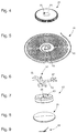
- the manufacturing method of the ceramic watch component comprises a first step intended to form, by photolithography on a substrate 1, a mold 3 provided with at least one cavity 2 1 , 2 2 as illustrated in FIG. figure 1 .
- Photolithography being a process known in itself, it will not be advantageously explained below.
- the mold 3 can be formed indifferently from a photosensitive resin of the positive or negative type.
- a negative photosensitive resin SU-8 type was used for its ease of structuring, its low cost and its ability to form layers up to 500 ⁇ m.
- one or more cavities 2 1 , 2 2 may be structured on the surface of the substrate 1. If several cavities 2 1 , 2 2 are structured, they may be identical or different patterns. We can also see, as an example in the figure 1 cavities 2 1 , 2 2 each of annular shape with a distal wall 6 1 , 6 2 substantially vertical and toothed and a proximal wall 4 1 , 4 2 substantially vertical. It is therefore clear that the clock component 21 that will be formed will be a toothed wheel 23 provided with a central recess 25 as illustrated in FIG. figure 4 .
- the photolithography may be of the stereolithography (also known as "SLA”) type, of the maskless type (also known by the abbreviation "MLA”) or of the variation mask type transmittance (also known as “gray scale lithography”).
- a photolithography of the mask type with a transmittance variation enables said at least one cavity 2 1 , 2 2 of the mold 3 to comprise at least one non-vertical wall to obtain for example a component of the type of the figure 13 as explained below.
- the first step can not be limited to a mold 3 with a single pattern per cavity 2 1 , 2 2 .
- the first step could also form a multi-level mold that is to say that at least two cavities of different patterns are formed concentrically one above the other to form a multi-level watch component.
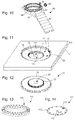
- the clock component 31 which will be formed will be a double toothed wheel 33, 37 which is provided with a central recess 35 as illustrated in FIG. figure 12 .
- such a mold 13 can be obtained by several successive photolithographies during the first step.
- the substrate 1 forms the bottom of the cavities 2 1 , 2 2 , 12 1 . Therefore, the substrate 1 can be formed based on silicon or ceramic according to the embodiment explained below. However, the bottom could alternatively be formed by a layer of the mold 3, 13.
- the bottom of the cavities could have a surface pattern arranged to form a decoration on the corresponding face of the watch component or, conversely, a polished surface giving a mirror polished appearance to the corresponding face of the watch component.
- the method may comprise, after the first mold forming step 3 or between each photolithography of the mold 13, a step of setting the thickness of the mold 3, 13 in order to homogenize the thickness of the mold 3 or at least one of the thicknesses of the mold 13.
- the method may optionally include a step of depositing a release layer to more easily release the precursor material blank and / or ceramic watch component at the end of the process.
- a release layer may be deposited on the entire upper surface of the mold 3, 13 or only a portion of the mold 3, 13 for example only in the cavities 2 1 2 2 , 12 1 , 12 2 or only on the bottom of the cavities 2 1 , 2 2 , 12 1 .
- Such a release layer could, for example, be a thin layer of boron nitride powder.
- such a layer allows a facilitated release but also compensation of the removal of the ceramic during the sintering step explained below.
- the second step of the method is intended to fill said at least one cavity 2 1 , 2 2 , 12 1 , 12 2 of the mold 3, 13 with a precursor material of a ceramic.
- the filling step is carried out by a liquid route.
- the filling step comprises a first phase for casting a slip in the mold 3, 13 followed, optionally, scraping for removing the excess slip.
- the slip may comprise a liquid material, ceramic powder and at least one adjuvant intended to facilitate the process.
- the liquid material may comprise preferentially deionized water or a solvent.
- the ceramic powder may comprise a wide variety of materials through the chosen liquid pathway.
- An oxide, carbide or metal nitride such as, for example, a zirconia or an alumina may be used.
- the mixture of several powders of different natures can also be envisaged. It has also been found that a grain size of less than 10 ⁇ m is desirable with respect to the final dimensions desired and in particular the small thickness indicated above.
- boron-based ceramic powder such as, for example, boron carbide (B 4 C) or titanium diboride (TiB 2 ), was particularly interesting.
- said at least one adjuvant of the slip may comprise a dispersant allowing the slip to form a homogeneous suspension especially during the casting phase.
- the filling step can be continued with a second phase for drying the slip to obtain the precursor material 1 , 2 of the ceramic as illustrated in FIG. figure 2 .
- this second phase is mainly to remove the liquid material from the slip, that is to say the water or solvent mentioned above.
- said at least one adjuvant of the slip may comprise a binder such as, for example, an organic binder.
- the method may include, prior to the third step explained below, a thickness step of the mold 3, 13 and the precursor material 1 5 5 2 in order to adjust the surface state and the thickness of the blank 7 1 , 7 2 of precursor material.
- the process is continued with a third step for removing the mold 3, 13 to release a blank 7 1 , 7 2 of precursor material 5 1 , 5 2 .
- a third step for removing the mold 3, 13 to release a blank 7 1 , 7 2 of precursor material 5 1 , 5 2 .
- the blanks 7 1 , 7 2 of precursor material 5 1 , 5 2 thus form toothed wheels with a central recess 8 1 , 8 2 .
- the mold removal step 3, 13 may include a dry etch, wet etch, or heat treatment.
- a plasma etching or a heat treatment of a few hundred degrees Celsius can be envisaged to carry out the third step.
- the process is continued with a fourth step intended to transform the blank 7 1 , 7 2 into a precursor material 1 , 5 2 into a ceramic clock component 21 and then, in a fifth step, to release the ceramic watch component 21 of the substrate 1.
- the method is continued with a fourth step intended to release the blank 7 1 , 7 2 of precursor material 1 , 5 2 of the substrate 1 and then, in a fifth step, to transform the blank 7 1, 7 2 5 precursor material 1 5 2 timepiece component 21 ceramic.
- the ceramic transformation step may, for example, comprise a first debinding phase intended to remove precursor material 1 , 2 , any additive provided during the process and then a second sintering phase.
- Each phase is mainly characterized by the temperature applied to the precursor material 5 1 , 5 2 .
- the temperature during the first phase can be between 300 and 700 ° C while the temperature during the second phase can be between 1400 and 1700 ° C.
- the step of removing the mold 3, 13 is carried out by heat treatment, the first debinding phase can be performed at the same time.
- a timepiece component 21, 31 with at least one level, totally monobloc polycrystalline ceramic whose dimensional accuracy is of the order of a few microns and whose shape can to be very varied.
- a watch component at a level such as, for example, a toothed wheel 23 illustrated in FIG. figure 4 provided with a central recess 25, a hairspring 41 illustrated at figure 5 provided with a shell 43 and a monobloc blade 45, all or part of an anchor 51 illustrated in FIG. figure 6 as the rod 53 and / or the pallets 55, a pad 61 illustrated in FIG. figure 7 equipped with a hole 65 and a cruet 63, an ice cream 71 illustrated in FIG. figure 8 provided with a surface curved upper, needles 81 illustrated in the figure 9 , a middle 99 or a link 92 of bracelet 94 illustrated in FIG. figure 10 .
- a multilevel watch component such as, for example, a mobile 31 illustrated in FIG. figure 12 provided with two single-piece gear wheels 33, 37 and a central recess 35, all or part of an anchor 51 illustrated in FIG. figure 6 as the rod 53 and / or the pallets 55 and / or the stinger 57, a pinion 101 illustrated in FIG. figure 13 provided with a singing toothing 103, a dial 111 illustrated in FIG. figure 14 equipped with a window 113, a decoration 115 and a lap of hours 117 or horns 97 provided with recesses for the bracelet bar 94, a ring 93 or a pusher 95 illustrated in FIG. figure 10 .
- the present invention is not limited to the illustrated example but is susceptible of various variations and modifications that will occur to those skilled in the art.
- the invention can not be limited to a dressing room or even to the watchmaking domain.
- nothing prevents the use of polycrystalline ceramics according to the invention for application in the field of tableware, jewelery or jewelery.
Landscapes
- Engineering & Computer Science (AREA)
- Chemical & Material Sciences (AREA)
- Ceramic Engineering (AREA)
- Manufacturing & Machinery (AREA)
- Structural Engineering (AREA)
- Materials Engineering (AREA)
- Organic Chemistry (AREA)
- Mechanical Engineering (AREA)
- Physics & Mathematics (AREA)
- Inorganic Chemistry (AREA)
- Optics & Photonics (AREA)
- Plasma & Fusion (AREA)
- General Physics & Mathematics (AREA)
- Micromachines (AREA)
Abstract
Fabrication d'un composant horloger en céramique obtenu par remplissage d'un moule structuré par photolithographie d'un matériau précurseur de la céramique souhaitée.
Description
- L'invention se rapporte à un procédé de fabrication d'un composant horloger en céramique et plus précisément à base de céramique polycristalline.
- Dans le domaine de l'horlogerie, il est connu de former des pièces de l'habillage en céramique polycristalline à l'aide d'un moulage par injection (également connu sous l'abréviation anglaise « CIM »). Ainsi, une matière, généralement appelée « feedstock », est injectée dans un moule sous pression puis des étapes de déliantage et de frittage sont réalisées pour obtenir la pièce en céramique polycristalline avec une grande cadence.
- Toutefois, l'étape d'injection génère des lignes de jonctions des fronts de la matière injectée qui oblige à une étape de retouche ainsi qu'à une fragilité mécanique localisée à ces jonctions. Il est également nécessaire de retirer les surplus de matière au niveau des zones d'injection.
- Enfin, le moulage par injection est difficilement applicable à la fabrication de pièces de faible épaisseur typiquement inférieure à 1 millimètre à cause de la difficulté à injecter la matière par des canaux fins mais également par la difficulté à démouler et à rectifier les pièces sans bris.
- Le but de la présente invention est de pallier tout ou partie les inconvénients cités précédemment en proposant un procédé de fabrication capable de former sans retouche un composant horloger en céramique polycristalline de faible épaisseur, sans défaut de planéité et avec une grande précision dimensionnelle.
- A cet effet, selon un premier mode de réalisation, l'invention se rapporte à un procédé de fabrication d'un composant horloger en céramique comportant les étapes suivantes :
- former, par photolithographie sur un substrat, un moule muni d'au moins une cavité ;
- remplir ladite au moins une cavité du moule à l'aide d'un matériau précurseur d'une céramique ;
- retirer le moule pour libérer une ébauche en matériau précurseur ;
- transformer l'ébauche en matériau précurseur en composant horloger en céramique ;
- libérer le composant horloger en céramique du substrat.
- De plus, selon un deuxième mode de réalisation, l'invention se rapporte à un procédé de fabrication d'un composant horloger en céramique comportant les étapes suivantes :
- former, par photolithographie sur un substrat, un moule muni d'au moins une cavité ;
- remplir ladite au moins une cavité du moule à l'aide d'un matériau précurseur d'une céramique ;
- retirer le moule pour libérer une ébauche en matériau précurseur ;
- libérer l'ébauche en matériau précurseur du substrat ;
- transformer l'ébauche en matériau précurseur en composant horloger en céramique.
- Conformément à d'autres variantes avantageuses de l'invention :
- le moule est formé à partir d'une résine photosensible du type positif ou négatif ;
- ladite au moins une cavité du moule comporte au moins une paroi non verticale ;
- le moule comporte plusieurs cavités ;
- deux cavités de motifs différents sont formées l'une au-dessus de l'autre concentriquement pour former un composant horloger à plusieurs niveaux ;
- au moins deux cavités adjacentes sont reliées par un canal pour former une plaquette avec plusieurs composants horlogers reliés entre eux ;
- le substrat est formé à base de silicium ou de céramique ;
- l'étape de remplissage est réalisée par voie liquide ;
- l'étape de remplissage comporte les phases suivantes ; couler une barbotine dans le moule et sécher la barbotine afin d'obtenir le matériau précurseur d'une céramique dans le moule ;
- la barbotine comporte une matière liquide, de la poudre de céramique et au moins un adjuvant destiné à faciliter le procédé ;
- la matière liquide comporte de l'eau ou un solvant ;
- la poudre de céramique comporte une taille de grains inférieure à 10 µm ;
- la poudre de céramique comporte du bore pour améliorer la tribologie du composant horloger ;
- ledit au moins un adjuvant comporte un liant permettant à l'ébauche en matériau précurseur à former une masse homogène à l'issue de la phase de séchage ;
- ledit au moins un adjuvant comporte un dispersant permettant à la barbotine de former une suspension homogène lors de la phase de coulage ;
- l'étape de retrait du moule comporte une attaque sèche, une attaque humide ou un traitement thermique ;
- le procédé comporte en outre, avant l'étape de remplissage du moule, une étape de dépôt d'une couche anti-adhérente permettant de retirer plus facilement le substrat ;
- le procédé comporte en outre, après l'étape de formation du moule, une étape de mise en épaisseur du moule afin d'homogénéiser son épaisseur ;
- le procédé comporte en outre, avant l'étape de retrait du moule, une étape de mise en épaisseur du moule et de l'ébauche en matériau précurseur afin d'ajuster l'état de surface et l'épaisseur de l'ébauche en matériau précurseur ;
- le composant horloger forme tout ou partie d'une pièce d'habillage ou d'un organe du mouvement d'une pièce d'horlogerie.
- D'autres particularités et avantages ressortiront clairement de la description qui en est faite ci-après, à titre indicatif et nullement limitatif, en référence aux dessins annexés, dans lesquels :
- les
figures 1 à 4 sont des représentations d'étapes successives du procédé selon l'invention ; - les
figures 5 à 10 sont des représentations de composants horlogers selon l'invention ; - les
figures 11 et 12 sont des représentations d'étapes successives du procédé selon une alternative de l'invention ; - les
figures 13 et 14 sont des représentations de composants horlogers selon une alternative de l'invention. - Le composant selon l'invention a été imaginé pour des applications dans le domaine horloger et est rendu nécessaire par la part croissante que tiennent les matériaux fragiles comme ceux à base de céramique. Les composants horlogers ont la caractéristique d'avoir une épaisseur très faible par rapport à leur surface principale en projection. Ainsi, une surface principale en projection peut typiquement comporter une longueur ponctuelle ou un diamètre compris entre 2 et 6 millimètres qui est élevé au regard de l'épaisseur comprise entre 10 à 400 µm.
- C'est pourquoi, l'invention se rapporte à un procédé de fabrication capable de former sans retouche un composant horloger en céramique polycristalline de faible épaisseur, sans défaut de planéité et avec une grande précision dimensionnelle. En effet, les retouches sur de si faible épaisseur de céramique est très difficile à réaliser sans occasionner des bris ou égrisures sur la céramique.
- On comprend donc que le composant horloger peut former tout ou partie d'une pièce d'habillage ou d'un organe du mouvement d'une pièce d'horlogerie. On peut, à titre d'exemple, envisager de former le spiral, le balancier, l'ancre, les ponts, la masse oscillante ou même les mobiles comme les roues d'échappement totalement ou partiellement à base de céramique. Il est également envisageable de former un boîtier, un cadran, un affichage, un décor, un index, une applique, un réhaut, une lunette, un poussoir, une couronne, un fond de boîtier, une aiguille ou un bracelet totalement ou partiellement à base de céramique selon l'invention.
- Afin de garantir la planéité et la précision dimensionnelle, l'invention se rapporte à un procédé de fabrication utilisant le remplissage d'un moule structuré par photolithographie d'un matériau précurseur de la céramique souhaitée. En effet, comme expliqué ci-dessous, le recours à la photolithographie apporte une très grande précision dimensionnelle au composant horloger en céramique.
- Le procédé de fabrication du composant horloger en céramique comporte une première étape destinée à former, par photolithographie sur un substrat 1, un moule 3 muni d'au moins une cavité 21, 22 comme illustré à la
figure 1 . La photolithographie étant un processus connu en soit, il ne sera pas d'avantage expliqué ci-dessous. - Le moule 3 peut être formé indifféremment à partir d'une résine photosensible du type positif ou négatif. Dans le cadre du développement, une résine photosensible négative du type SU-8 a été utilisée pour sa facilité de structuration, son faible coût et sa capacité à former des couches jusqu'à 500 µm.
- Comme visible à la
figure 1 , une ou plusieurs cavités 21, 22 peut être structurée à la surface du substrat 1. Si plusieurs cavités 21, 22 sont structurées, elles peuvent être de motifs identiques ou différents. On peut également voir, à titre d'exemple à lafigure 1 , des cavités 21, 22 chacune de forme annulaire avec une paroi distale 61, 62 sensiblement verticale et dentée et une paroi proximale 41, 42 sensiblement verticale. On comprend donc que le composant horloger 21 qui sera formé, sera une roue dentée 23 munie d'un évidement central 25 comme illustré à lafigure 4 . - Bien évidemment, le processus de cette première étape peut être adapté suivant les formes de composant souhaitées. Ainsi, de manière non limitative, la photolithographie peut être du type stéréolithographie (également connu sous l'abréviation anglaise « SLA »), du type sans masque (également connu sous l'abréviation anglaise « MLA ») ou du type à masque à variation de transmittance (également connu sous l'expression anglaise « gray scale lithography »).
- En effet, à titre d'exemple, une photolithographie du type à masque à variation de transmittance permet à ladite au moins une cavité 21, 22 du moule 3 de comporter au moins une paroi non verticale pour obtenir par exemple un composant du type de la
figure 13 comme expliqué ci-dessous. - De plus, la première étape ne saurait se limiter à un moule 3 avec un seul motif par cavité 21, 22. La première étape pourrait également former un moule à plusieurs niveaux c'est-à-dire qu'au moins deux cavités de motifs différents soient formées concentriquement l'une au-dessus de l'autre pour former un composant horloger à plusieurs niveaux.
- Selon une alternative illustrée à la
figure 11 , on peut voir un moule 13 avec une empreinte 11 comportant une cavité inférieure 121 de forme annulaire avec une paroi distale 161 sensiblement verticale et dentée et une paroi proximale 141 sensiblement verticale, et une cavité supérieure 122, plus large et concentrique par rapport à la cavité inférieure 121, de forme annulaire avec une paroi distale 162 sensiblement verticale et dentée et une paroi proximale 142 sensiblement verticale. On comprend donc que le composant horloger 31 qui sera formé, sera une double roue dentée 33, 37 monobloc qui est munie d'un évidement central 35 comme illustré à lafigure 12 . A titre d'exemple, un tel moule 13 peut être obtenu par plusieurs photolithographies successives lors de la première étape. - Il est également parfaitement envisageable qu'au moins deux cavités adjacentes soient reliées par un canal pour former une plaquette avec plusieurs composants horlogers reliés entre eux. On permettrait alors une manipulation en plaquette à la manière d'une plaquette de silicium après gravage de composants.
- Dans les exemples des
figures 1 et11 , le substrat 1 forme le fond des cavités 21, 22, 121. Par conséquent, le substrat 1 peut être formé à base de silicium ou de céramique suivant le mode de réalisation expliqué ci-dessous. Toutefois, le fond pourrait alternativement être formé par une couche du moule 3, 13. - Quelle que soit la manière de former le fond des cavités, il apparaît immédiatement que son état de surface peut être avantageusement choisi afin de définir l'aspect de la face correspondante du composant horloger. A titre d'exemples, le fond des cavités pourrait avoir une structuration en surface agencée pour former un décor sur la face correspondante du composant horloger ou, au contraire, une surface polie donnant un aspect poli miroir à la face correspondante du composant horloger.
- Optionnellement, le procédé peut comporter après la première étape de formation du moule 3 ou entre chaque photolithographie du moule 13, une étape de mise en épaisseur du moule 3, 13 afin d'homogénéiser l'épaisseur du moule 3 ou au moins une des épaisseurs du moule 13.
- De plus, avant le début de la deuxième étape expliquée ci-dessous, le procédé peut, de manière optionnelle, comporter une étape de dépôt d'une couche anti-adhérente permettant de libérer plus facilement l'ébauche en matériau précurseur et/ou du composant horloger en céramique à la fin du procédé. Une telle couche pourrait être déposée sur la totalité de la surface supérieure du moule 3, 13 ou uniquement sur une partie du moule 3, 13 comme par exemple uniquement dans les cavités 21, 22, 121, 122 ou uniquement sur le fond des cavités 21, 22, 121. Une telle couche anti-adhérente pourrait, par exemple, être une fine couche de poudre de nitrure de bore. Avantageusement selon l'invention, une telle couche autorise une libération facilitée mais également de compensation du retrait de la céramique lors de l'étape de frittage expliquée ci-dessous.
- La deuxième étape du procédé est destinée à remplir ladite au moins une cavité 21, 22, 121, 122 du moule 3, 13 à l'aide d'un matériau précurseur d'une céramique. Préférentiellement selon l'invention, l'étape de remplissage est réalisée par voie liquide.
- Ainsi, selon un exemple préféré, l'étape de remplissage comporte une première phase destinée à couler une barbotine dans le moule 3, 13 suivie, éventuellement, d'un raclage destiné à retirer le surplus de barbotine. Selon l'invention, la barbotine peut comporter une matière liquide, de la poudre de céramique et au moins un adjuvant destiné à faciliter le procédé. La matière liquide peut comporter de l'eau préférentiellement déionisée ou un solvant.
- La poudre de céramique peut comporter une grande variété de matériaux grâce à la voie liquide choisie. Un oxyde, carbure ou nitrure de métal comme, par exemple, une zircone ou une alumine peut être utilisée. Bien entendu, le mélange de plusieurs poudres de natures différentes peut également être envisagé. Il est également apparu qu'une taille de grains inférieure à 10 µm était souhaitable par rapport aux dimensions finales souhaitées et notamment la faible épaisseur indiquée ci-dessus.
- Dans le but notamment de fabriquer des composants horlogers capables de transmettre des forces et d'avoir un faible coefficient de frottement, il est apparu qu'une poudre de céramique à base de bore, comme, par exemple, du carbure de bore (B4C) ou du diborure de titane (TiB2), était particulièrement intéressante.
- A titre d'exemple, ledit au moins un adjuvant de la barbotine peut comporter un dispersant permettant à la barbotine de former une suspension homogène notamment lors de la phase de coulage.
- Ainsi, selon l'exemple préféré, l'étape de remplissage peut se poursuivre avec une deuxième phase destinée à sécher la barbotine afin d'obtenir le matériau précurseur 51, 52 de la céramique comme illustré à la
figure 2 . On comprend que le but de cette deuxième phase est principalement de retirer la matière liquide de la barbotine, c'est-à-dire l'eau ou le solvant cité ci-dessus. - Afin de permettre au matériau précurseur 51, 52 de former une masse homogène à l'issue de la phase de séchage, ledit au moins un adjuvant de la barbotine peut comporter un liant comme, par exemple, un liant organique.
- Optionnellement, le procédé peut comporter, avant la troisième étape expliquée ci-dessous, une étape de mise en épaisseur du moule 3, 13 et du matériau précurseur 51, 52 afin d'ajuster l'état de surface et l'épaisseur de l'ébauche 71, 72 en matériau précurseur.
- Le procédé se poursuit avec une troisième étape destinée à retirer le moule 3, 13 pour libérer une ébauche 71, 72 en matériau précurseur 51, 52. Dans l'exemple de la
figure 3 , on peut voir que les ébauche 71, 72 en matériau précurseur 51, 52 forment ainsi des roues dentées avec un évidement central 81, 82. - L'étape de retrait du moule 3, 13 peut comporter une attaque sèche, une attaque humide ou un traitement thermique. Typiquement, dans le cas cité ci-dessus d'une résine photosensible du type SU-8, une attaque plasma ou un traitement thermique de quelques centaines de degrés Celsius peuvent être envisagés pour réaliser la troisième étape.
- Suivant un premier mode de réalisation, le procédé se poursuit avec une quatrième étape destinée à transformer l'ébauche 71, 72 en matériau précurseur 51, 52 en composant horloger 21 en céramique puis, dans une cinquième étape, à libérer le composant horloger 21 en céramique du substrat 1.
- Suivant un deuxième mode de réalisation, le procédé se poursuit avec une quatrième étape destinée à libérer l'ébauche 71, 72 en matériau précurseur 51, 52 du substrat 1 puis, dans une cinquième étape, à transformer l'ébauche 71, 72 en matériau précurseur 51, 52 en composant horloger 21 en céramique.
- Quel que soit le mode de réalisation, l'étape de transformation en céramique peut, par exemple, comporter une première phase de déliantage destinée à retirer du matériau précurseur 51, 52, tout adjuvant apporté lors du procédé puis une deuxième phase de frittage. Chaque phase est principalement caractérisée par la température appliquée au matériau précurseur 51, 52. Ainsi, la température lors de la première phase peut être comprise entre 300 et 700°C alors que la température, lors de la deuxième phase, peut être comprise entre 1400 et 1700°C.
- On comprend donc que si l'étape de retrait du moule 3, 13 est réalisée par traitement thermique, la première phase de déliantage peut être réalisée en même temps.
- A l'issue du procédé, on obtient, avantageusement selon l'invention, un composant horloger 21, 31 à au moins un niveau, totalement monobloc en céramique polycristalline dont la précision dimensionnelle est de l'ordre de quelques microns et dont la forme peut être très variée.
- Ainsi, de manière non limitative, il est possible de fabriquer un composant horloger à un niveau comme, par exemple, une roue dentée 23 illustrée à la
figure 4 munie d'un évidement central 25, un spiral 41 illustré à lafigure 5 muni d'une virole 43 et d'une lame 45 monoblocs, tout ou partie d'une ancre 51 illustrée à lafigure 6 comme la baguette 53 et/ou les palettes 55, un coussinet 61 illustré à lafigure 7 muni d'un trou 65 et d'un huilier 63, une glace 71 illustrée à lafigure 8 munie d'une surface supérieure bombée, des aiguilles 81 illustrées à lafigure 9 , une carrure 99 ou un maillon 92 de bracelet 94 illustrés à lafigure 10 . - De plus, de manière non limitative, il est possible de fabriquer un composant horloger à plusieurs niveaux comme, par exemple, un mobile 31 illustré à la
figure 12 muni de deux roues dentées 33, 37 monoblocs et d'un évidement central 35, tout ou partie d'une ancre 51 illustrée à lafigure 6 comme la baguette 53 et/ou les palettes 55 et/ou le dard 57, un pignon 101 illustré à lafigure 13 muni d'une denture de chant 103, un cadran 111 illustré à lafigure 14 muni d'un guichet 113, d'un décor 115 et d'un tour d'heures 117 ou des cornes 97 munies d'évidements pour la barrette de bracelet 94, une couronne 93 ou un poussoir 95 illustrés à lafigure 10 . - Bien entendu, la présente invention ne se limite pas à l'exemple illustré mais est susceptible de diverses variantes et modifications qui apparaîtront à l'homme de l'art. En particulier, l'invention ne saurait se limiter à une pièce d'habillage ou même au domaine horloger. Ainsi, à titre d'exemple, rien n'empêche d'utiliser la céramique polycristalline selon l'invention pour une application dans le domaine des arts de la table, de la bijouterie ou de la joaillerie.
Claims (21)
- Procédé de fabrication d'un composant horloger (21, 31, 41, 51, 61, 71, 81, 93, 95, 94, 97, 99, 101, 111) en céramique comportant les étapes suivantes :- former, par photolithographie sur un substrat (1), un moule (3, 13) muni d'au moins une cavité (21, 22, 121, 122) ;- remplir ladite au moins une cavité (21, 22, 121, 122) du moule (3, 13) à l'aide d'un matériau précurseur (51, 52) d'une céramique ;- retirer le moule (3, 13) pour libérer une ébauche (71, 72) en matériau précurseur ;- transformer l'ébauche (71, 72) en matériau précurseur (51, 52) en composant horloger (21, 31, 41, 51, 61, 71, 81, 93, 95, 94, 97, 99, 101, 111) en céramique ;- libérer le composant horloger (21, 31, 41, 51, 61, 71, 81, 93, 95, 94, 97, 99, 101, 111) en céramique du substrat (1).
- Procédé de fabrication d'un composant horloger (21, 31, 41, 51, 61, 71, 81, 93, 95, 94, 97, 99, 101, 111) en céramique comportant les étapes suivantes :- former, par photolithographie sur un substrat (1), un moule (3, 13) muni d'au moins une cavité (21, 22, 121, 122) ;- remplir ladite au moins une cavité (21, 22, 121, 122) du moule (3, 13) à l'aide d'un matériau précurseur (51, 52) d'une céramique ;- retirer le moule (3, 13) pour libérer une ébauche (71, 72) en matériau précurseur (51, 52) ;- libérer l'ébauche (71, 72) en matériau précurseur (51, 52) du substrat (1) ;- transformer l'ébauche (71, 72) en matériau précurseur (51, 52) en composant horloger (21, 31, 41, 51, 61, 71, 81, 93, 95, 94, 97, 99, 101, 111) en céramique.
- Procédé selon la revendication 1 ou 2, caractérisé en ce que le moule (3, 13) est formé à partir d'une résine photosensible du type positif ou négatif.
- Procédé selon l'une des revendications précédentes, caractérisé en ce que ladite au moins une cavité (21, 22, 121, 122) du moule (3, 13) comporte au moins une paroi non verticale.
- Procédé selon l'une des revendications précédentes, caractérisé en ce que le moule (3, 13) comporte plusieurs cavités (21, 22, 121, 122).
- Procédé selon la revendication précédente, caractérisé en ce que deux cavités (21, 22, 121, 122) de motifs différents sont formées l'une au-dessus de l'autre concentriquement pour former un composant horloger (21, 31, 41, 51, 61, 71, 81, 93, 95, 94, 97, 99, 101, 111) à plusieurs niveaux.
- Procédé selon la revendication 5 ou 6, caractérisé en ce que au moins deux cavités (21, 22, 121, 122) adjacentes sont reliées par un canal pour former une plaquette avec plusieurs composants horlogers (21, 31, 41, 51, 61, 71, 81, 93, 95, 94, 97, 99, 101, 111) reliés entre eux.
- Procédé selon l'une des revendications précédentes, caractérisé en ce que le substrat (1) est formé à base de silicium ou de céramique.
- Procédé selon l'une des revendications précédentes, caractérisé en ce que l'étape de remplissage est réalisée par voie liquide.
- Procédé selon la revendication précédente, caractérisé en ce que l'étape de remplissage comporte les phases suivantes :- couler une barbotine dans le moule (3, 13) ;- sécher la barbotine afin d'obtenir le matériau précurseur (51, 52) d'une céramique dans le moule (3, 13).
- Procédé selon la revendication précédente, caractérisé en ce que la barbotine comporte une matière liquide, de la poudre de céramique et au moins un adjuvant destiné à faciliter le procédé.
- Procédé selon la revendication précédente, caractérisé en ce que la matière liquide comporte de l'eau ou un solvant.
- Procédé selon la revendication 11 ou 12, caractérisé en ce que la poudre de céramique comporte une taille de grains inférieure à 10 µm.
- Procédé selon l'une des revendications 11 à 13, caractérisé en ce que la poudre de céramique comporte du bore pour améliorer la tribologie du composant horloger (21, 31, 41, 51, 61, 71, 81, 93, 95, 94, 97, 99, 101, 111).
- Procédé selon l'une des revendications 11 à 14, caractérisé en ce que ledit au moins un adjuvant comporte un liant permettant à l'ébauche (71, 72) en matériau précurseur (51, 52) à former une masse homogène à l'issue de la phase de séchage.
- Procédé selon l'une des revendications 11 à 15, caractérisé en ce que ledit au moins un adjuvant comporte un dispersant permettant à la barbotine de former une suspension homogène lors de la phase de coulage.
- Procédé selon l'une des revendications précédentes, caractérisé en ce que l'étape de retrait du moule (3, 13) comporte une attaque sèche, une attaque humide ou un traitement thermique.
- Procédé selon l'une des revendications précédentes, caractérisé en ce que le procédé comporte en outre, avant l'étape de remplissage du moule (3, 13), une étape de dépôt d'une couche anti-adhérente permettant de retirer plus facilement le substrat (1).
- Procédé selon l'une des revendications précédentes, caractérisé en ce que le procédé comporte en outre, après l'étape de formation du moule (3, 13), une étape de mise en épaisseur du moule (3, 13) afin d'homogénéiser son épaisseur.
- Procédé selon l'une des revendications précédentes, caractérisé en ce que le procédé comporte en outre, avant l'étape de retrait du moule (3, 13), une étape de mise en épaisseur du moule (3, 13) et de l'ébauche (71, 72) en matériau précurseur (51, 52) afin d'ajuster l'état de surface et l'épaisseur de l'ébauche (71, 72) en matériau précurseur (51, 52).
- Procédé selon l'une des revendications précédentes, caractérisé en ce que le composant horloger (21, 31, 41, 51, 61, 71, 81, 93, 95, 94, 97, 99, 101, 111) forme tout ou partie d'une pièce d'habillage ou d'un organe du mouvement d'une pièce d'horlogerie.
Priority Applications (1)
| Application Number | Priority Date | Filing Date | Title |
|---|---|---|---|
| EP16175797.6A EP3260932A1 (fr) | 2016-06-22 | 2016-06-22 | Procédé de fabrication d'un composant horloger en céramique |
Applications Claiming Priority (1)
| Application Number | Priority Date | Filing Date | Title |
|---|---|---|---|
| EP16175797.6A EP3260932A1 (fr) | 2016-06-22 | 2016-06-22 | Procédé de fabrication d'un composant horloger en céramique |
Publications (1)
| Publication Number | Publication Date |
|---|---|
| EP3260932A1 true EP3260932A1 (fr) | 2017-12-27 |
Family
ID=56148317
Family Applications (1)
| Application Number | Title | Priority Date | Filing Date |
|---|---|---|---|
| EP16175797.6A Withdrawn EP3260932A1 (fr) | 2016-06-22 | 2016-06-22 | Procédé de fabrication d'un composant horloger en céramique |
Country Status (1)
| Country | Link |
|---|---|
| EP (1) | EP3260932A1 (fr) |
Cited By (5)
| Publication number | Priority date | Publication date | Assignee | Title |
|---|---|---|---|---|
| EP3670440A1 (fr) | 2018-12-21 | 2020-06-24 | Rolex Sa | Procédé de fabrication d'un composant horloger |
| EP3670441A1 (fr) | 2018-12-21 | 2020-06-24 | Rolex Sa | Procédé de fabrication d'un composant horloger |
| CN112261881A (zh) * | 2018-06-14 | 2021-01-22 | 尼科创业贸易有限公司 | 感应加热系统和加热器 |
| CN113799233A (zh) * | 2020-06-12 | 2021-12-17 | 柯马杜股份有限公司 | 用于制造设有聚合物涂层的装饰性硬质材料部件的方法 |
| EP3956731A2 (fr) * | 2019-04-15 | 2022-02-23 | Rolex Sa | Composant horloger de type came |
-
2016
- 2016-06-22 EP EP16175797.6A patent/EP3260932A1/fr not_active Withdrawn
Non-Patent Citations (8)
| Title |
|---|
| "Development of Implantable Electrodes Based on Polymer Derived Ceramics", 29 May 2015, Lausanne, article JONAS GROSSENBACHER: "Development of Implantable Electrodes Based on Polymer Derived Ceramics", pages: 64 - 66, XP055331070, DOI: 10.5075/epfl-thesis-5983 * |
| ALVARO MATA ET AL: "Fabrication of multi-layer SU-8 microstructures", JOURNAL OF MICROMECHANICS & MICROENGINEERING, INSTITUTE OF PHYSICS PUBLISHING, BRISTOL, GB, vol. 16, no. 2, 1 February 2006 (2006-02-01), pages 276 - 284, XP020104907, ISSN: 0960-1317, DOI: 10.1088/0960-1317/16/2/012 * |
| KION: "TB1: KiON Ceraset Polyureasilazane and KiON Ceraset Polysilazane 20", 11 June 2014 (2014-06-11), XP055330651, Retrieved from the Internet <URL:https://web-beta.archive.org/web/20140611110437/http://www.kiondefense.com/bulletins/TB1.pdf> [retrieved on 20161220] * |
| LIEW L-A ET AL: "Fabrication of SiCN ceramic MEMS using injectable polymer-precursor technique", SENSORS AND ACTUATORS A: PHYSICAL, ELSEVIER BV, NL, vol. 89, no. 1-2, 20 March 2001 (2001-03-20), pages 64 - 70, XP004317247, ISSN: 0924-4247, DOI: 10.1016/S0924-4247(00)00545-8 * |
| LINDQVIST K M ET AL: "Indirect solid freeform fabrication by binder assisted slip casting", JOURNAL OF THE EUROPEAN CERAMIC SOCIETY, ELSEVIER SCIENCE PUBLISHERS, BARKING, ESSEX, GB, vol. 25, no. 16, 1 November 2005 (2005-11-01), pages 3539 - 3545, XP027618300, ISSN: 0955-2219, [retrieved on 20051101] * |
| MARTIN HEULE ET AL: "Micro Colloidal fabrication of Ceramics based on Suspensions and Photoresist Masks", JOURNAL OF PHOTOPOLYMER SCIENCE AND TECHNOLOGY VOLUME 14, NUMBER 3, vol. 14, no. 3, 8 April 2006 (2006-04-08), pages 449 - 452, XP055328334, Retrieved from the Internet <URL:http://doi.org/10.2494/photopolymer.14.449> [retrieved on 20161212], DOI: 10.2494/photopolymer.14.449 * |
| RALF RIEDEL ET AL: "Silicon-Based Polymer-Derived Ceramics: Synthesis Properties and Applications-A Review", JOURNAL OF THE CERAMIC SOCIETY OF JAPAN, vol. 114, no. 6, 1 June 2006 (2006-06-01), pages 125 - 444, XP055331405, DOI: 10.2109/jcersj.114.425 * |
| URS P SCHÖNHOLZER ET AL: "Microfabrication of Ceramics by Filling of Photoresist Molds", ADVANCED MATERIALS, vol. 12, no. 17, 13 September 2000 (2000-09-13), pages 1261 - 1263, XP055331060, DOI: 10.1002/1521-4095(200009)12:17<1261::AID-ADMA1261>3.0.CO;2-4 * |
Cited By (14)
| Publication number | Priority date | Publication date | Assignee | Title |
|---|---|---|---|---|
| CN112261881A (zh) * | 2018-06-14 | 2021-01-22 | 尼科创业贸易有限公司 | 感应加热系统和加热器 |
| US11960205B2 (en) | 2018-12-21 | 2024-04-16 | Rolex Sa | Method for manufacturing a horology component |
| CN111352308A (zh) * | 2018-12-21 | 2020-06-30 | 劳力士有限公司 | 钟表构件的制造方法 |
| JP2020118676A (ja) * | 2018-12-21 | 2020-08-06 | ロレックス・ソシエテ・アノニムRolex Sa | 時計部品の製造方法 |
| JP2020118677A (ja) * | 2018-12-21 | 2020-08-06 | ロレックス・ソシエテ・アノニムRolex Sa | 時計部品の製造方法 |
| EP3670441A1 (fr) | 2018-12-21 | 2020-06-24 | Rolex Sa | Procédé de fabrication d'un composant horloger |
| US11803121B2 (en) | 2018-12-21 | 2023-10-31 | Rolex Sa | Method for manufacturing a horology component |
| EP3670440A1 (fr) | 2018-12-21 | 2020-06-24 | Rolex Sa | Procédé de fabrication d'un composant horloger |
| JP7652530B2 (ja) | 2018-12-21 | 2025-03-27 | ロレックス・ソシエテ・アノニム | 時計部品の製造方法 |
| JP7652531B2 (ja) | 2018-12-21 | 2025-03-27 | ロレックス・ソシエテ・アノニム | 時計部品の製造方法 |
| CN111352308B (zh) * | 2018-12-21 | 2025-08-01 | 劳力士有限公司 | 钟表构件的制造方法 |
| EP3956731A2 (fr) * | 2019-04-15 | 2022-02-23 | Rolex Sa | Composant horloger de type came |
| CN113799233A (zh) * | 2020-06-12 | 2021-12-17 | 柯马杜股份有限公司 | 用于制造设有聚合物涂层的装饰性硬质材料部件的方法 |
| US12235610B2 (en) | 2020-06-12 | 2025-02-25 | Comadur Sa | Method for manufacturing an ornamental hard material part provided with a polymer coating |
Similar Documents
| Publication | Publication Date | Title |
|---|---|---|
| EP2856903B1 (fr) | Elément céramique incrusté d'au moins un décor en céramique | |
| EP2259997B1 (fr) | Pièce de micromécanique composite silicium-métal et son procédé de fabrication | |
| EP2855400B1 (fr) | Elément céramique incrusté d'au moins un décor en céramique composite | |
| EP2230208B1 (fr) | Moule pour galvanoplastie et son procédé de fabrication | |
| EP3126914A1 (fr) | Procede de fabrication d'un composant horloger pourvu d'un insert en matiere composite, composant horloger et piece d'horlogerie associes | |
| EP3066044B1 (fr) | Pièce de micromécanique creuse, à plusieurs niveaux fonctionnels et monobloc en un matériau à base d'un allotrope synthétique du carbone | |
| EP3377247B1 (fr) | Procede de fabrication d'une piece en metal amorphe | |
| EP3591099A1 (fr) | Procede de fabrication d'une piece en ceramique revetue au moins partiellement d'une couche electriquement conductrice | |
| EP3670441A1 (fr) | Procédé de fabrication d'un composant horloger | |
| EP3168058B1 (fr) | Procédé de fabrication d'une pièce métallique avec au moins un motif a illusion d'optique | |
| EP3622846B1 (fr) | Procede d'assemblage d'au moins deux elements | |
| CH712599A2 (fr) | Procédé de fabrication d'un composant horloger en céramique. | |
| EP4111264A1 (fr) | Composant horloger en silicium pour pièce d'horlogerie | |
| CH710716B1 (fr) | Procédé de fabrication d'une pièce avec au moins un décor. | |
| CH715336A2 (fr) | Procédé d'assemblage d'au moins deux éléments et composant d'habillage ainsi formé. | |
| EP4332688B1 (fr) | Composant horloger incrusté et son procédé de fabrication | |
| EP4307053B1 (fr) | Procédé de fabrication d'un composant horloger | |
| FR3104042A1 (fr) | Procédé de fabrication d’une pièce creuse à l’aide d’un noyau | |
| EP2881808A2 (fr) | Procédé de fabrication d'un composant horloger | |
| CH711248A2 (fr) | Pièce à base de silicium avec au moins un chanfrein et son procédé de fabrication. | |
| CH715153B1 (fr) | Procédé de fabrication d'une pièce en céramique revêtue au moins partiellement d'une couche électriquement conductrice. | |
| CH711247B1 (fr) | Pièce de micromécanique avec une surface de contact diminuée et son procédé de fabrication. | |
| EP4729206A1 (fr) | Procédé de surmoulage | |
| FR3167321A1 (fr) | Noyau pour procédé de fonderie et procédé de fabrisation | |
| CH706576A2 (fr) | Elément céramique incrusté d'au moins un décor en céramique composite. |
Legal Events
| Date | Code | Title | Description |
|---|---|---|---|
| PUAI | Public reference made under article 153(3) epc to a published international application that has entered the european phase |
Free format text: ORIGINAL CODE: 0009012 |
|
| AK | Designated contracting states |
Kind code of ref document: A1 Designated state(s): AL AT BE BG CH CY CZ DE DK EE ES FI FR GB GR HR HU IE IS IT LI LT LU LV MC MK MT NL NO PL PT RO RS SE SI SK SM TR |
|
| AX | Request for extension of the european patent |
Extension state: BA ME |
|
| STAA | Information on the status of an ep patent application or granted ep patent |
Free format text: STATUS: THE APPLICATION IS DEEMED TO BE WITHDRAWN |
|
| 18D | Application deemed to be withdrawn |
Effective date: 20180628 |