EP3260903A1 - Endoscope system - Google Patents
Endoscope system Download PDFInfo
- Publication number
- EP3260903A1 EP3260903A1 EP15882740.2A EP15882740A EP3260903A1 EP 3260903 A1 EP3260903 A1 EP 3260903A1 EP 15882740 A EP15882740 A EP 15882740A EP 3260903 A1 EP3260903 A1 EP 3260903A1
- Authority
- EP
- European Patent Office
- Prior art keywords
- image
- denotes
- diff
- lens
- images
- Prior art date
- Legal status (The legal status is an assumption and is not a legal conclusion. Google has not performed a legal analysis and makes no representation as to the accuracy of the status listed.)
- Withdrawn
Links
- 230000003287 optical effect Effects 0.000 claims abstract description 165
- 230000014509 gene expression Effects 0.000 claims abstract description 63
- 230000015572 biosynthetic process Effects 0.000 claims abstract description 17
- 239000002131 composite material Substances 0.000 claims abstract description 16
- 238000003786 synthesis reaction Methods 0.000 claims abstract description 15
- 238000006243 chemical reaction Methods 0.000 claims abstract description 10
- 230000004075 alteration Effects 0.000 abstract description 41
- 238000010586 diagram Methods 0.000 description 30
- 201000009310 astigmatism Diseases 0.000 description 24
- 230000005499 meniscus Effects 0.000 description 21
- 230000010287 polarization Effects 0.000 description 20
- 238000003702 image correction Methods 0.000 description 10
- 230000000694 effects Effects 0.000 description 5
- 230000002093 peripheral effect Effects 0.000 description 5
- JNDMLEXHDPKVFC-UHFFFAOYSA-N aluminum;oxygen(2-);yttrium(3+) Chemical compound [O-2].[O-2].[O-2].[Al+3].[Y+3] JNDMLEXHDPKVFC-UHFFFAOYSA-N 0.000 description 4
- 229910019901 yttrium aluminum garnet Inorganic materials 0.000 description 4
- 239000011248 coating agent Substances 0.000 description 3
- 238000000576 coating method Methods 0.000 description 3
- 238000005520 cutting process Methods 0.000 description 3
- 230000002349 favourable effect Effects 0.000 description 3
- 239000011521 glass Substances 0.000 description 3
- 238000003384 imaging method Methods 0.000 description 3
- 238000004519 manufacturing process Methods 0.000 description 3
- 239000004065 semiconductor Substances 0.000 description 3
- 239000006059 cover glass Substances 0.000 description 2
- 238000003745 diagnosis Methods 0.000 description 2
- 239000000463 material Substances 0.000 description 2
- 238000000034 method Methods 0.000 description 2
- 230000004304 visual acuity Effects 0.000 description 2
- XLYOFNOQVPJJNP-UHFFFAOYSA-N water Substances O XLYOFNOQVPJJNP-UHFFFAOYSA-N 0.000 description 2
- 241000714933 Chryseobacterium nakagawai Species 0.000 description 1
- 239000008280 blood Substances 0.000 description 1
- 210000004369 blood Anatomy 0.000 description 1
- 230000015556 catabolic process Effects 0.000 description 1
- 238000006731 degradation reaction Methods 0.000 description 1
- 230000003292 diminished effect Effects 0.000 description 1
- 238000009826 distribution Methods 0.000 description 1
- 238000001839 endoscopy Methods 0.000 description 1
- 230000003902 lesion Effects 0.000 description 1
- 239000011159 matrix material Substances 0.000 description 1
- 239000005342 prism glass Substances 0.000 description 1
- 230000001105 regulatory effect Effects 0.000 description 1
- 229920006395 saturated elastomer Polymers 0.000 description 1
- 238000012216 screening Methods 0.000 description 1
Images






Classifications
-
- A—HUMAN NECESSITIES
- A61—MEDICAL OR VETERINARY SCIENCE; HYGIENE
- A61B—DIAGNOSIS; SURGERY; IDENTIFICATION
- A61B1/00—Instruments for performing medical examinations of the interior of cavities or tubes of the body by visual or photographical inspection, e.g. endoscopes; Illuminating arrangements therefor
- A61B1/00002—Operational features of endoscopes
- A61B1/00004—Operational features of endoscopes characterised by electronic signal processing
- A61B1/00009—Operational features of endoscopes characterised by electronic signal processing of image signals during a use of endoscope
-
- A—HUMAN NECESSITIES
- A61—MEDICAL OR VETERINARY SCIENCE; HYGIENE
- A61B—DIAGNOSIS; SURGERY; IDENTIFICATION
- A61B1/00—Instruments for performing medical examinations of the interior of cavities or tubes of the body by visual or photographical inspection, e.g. endoscopes; Illuminating arrangements therefor
- A61B1/00064—Constructional details of the endoscope body
- A61B1/00071—Insertion part of the endoscope body
- A61B1/0008—Insertion part of the endoscope body characterised by distal tip features
- A61B1/00096—Optical elements
-
- A—HUMAN NECESSITIES
- A61—MEDICAL OR VETERINARY SCIENCE; HYGIENE
- A61B—DIAGNOSIS; SURGERY; IDENTIFICATION
- A61B1/00—Instruments for performing medical examinations of the interior of cavities or tubes of the body by visual or photographical inspection, e.g. endoscopes; Illuminating arrangements therefor
- A61B1/00163—Optical arrangements
- A61B1/00186—Optical arrangements with imaging filters
-
- A—HUMAN NECESSITIES
- A61—MEDICAL OR VETERINARY SCIENCE; HYGIENE
- A61B—DIAGNOSIS; SURGERY; IDENTIFICATION
- A61B1/00—Instruments for performing medical examinations of the interior of cavities or tubes of the body by visual or photographical inspection, e.g. endoscopes; Illuminating arrangements therefor
- A61B1/00163—Optical arrangements
- A61B1/00188—Optical arrangements with focusing or zooming features
-
- A—HUMAN NECESSITIES
- A61—MEDICAL OR VETERINARY SCIENCE; HYGIENE
- A61B—DIAGNOSIS; SURGERY; IDENTIFICATION
- A61B1/00—Instruments for performing medical examinations of the interior of cavities or tubes of the body by visual or photographical inspection, e.g. endoscopes; Illuminating arrangements therefor
- A61B1/00163—Optical arrangements
- A61B1/00193—Optical arrangements adapted for stereoscopic vision
-
- A—HUMAN NECESSITIES
- A61—MEDICAL OR VETERINARY SCIENCE; HYGIENE
- A61B—DIAGNOSIS; SURGERY; IDENTIFICATION
- A61B1/00—Instruments for performing medical examinations of the interior of cavities or tubes of the body by visual or photographical inspection, e.g. endoscopes; Illuminating arrangements therefor
- A61B1/04—Instruments for performing medical examinations of the interior of cavities or tubes of the body by visual or photographical inspection, e.g. endoscopes; Illuminating arrangements therefor combined with photographic or television appliances
- A61B1/05—Instruments for performing medical examinations of the interior of cavities or tubes of the body by visual or photographical inspection, e.g. endoscopes; Illuminating arrangements therefor combined with photographic or television appliances characterised by the image sensor, e.g. camera, being in the distal end portion
- A61B1/051—Details of CCD assembly
-
- G—PHYSICS
- G02—OPTICS
- G02B—OPTICAL ELEMENTS, SYSTEMS OR APPARATUS
- G02B13/00—Optical objectives specially designed for the purposes specified below
- G02B13/04—Reversed telephoto objectives
-
- G—PHYSICS
- G02—OPTICS
- G02B—OPTICAL ELEMENTS, SYSTEMS OR APPARATUS
- G02B17/00—Systems with reflecting surfaces, with or without refracting elements
- G02B17/02—Catoptric systems, e.g. image erecting and reversing system
- G02B17/04—Catoptric systems, e.g. image erecting and reversing system using prisms only
-
- G—PHYSICS
- G02—OPTICS
- G02B—OPTICAL ELEMENTS, SYSTEMS OR APPARATUS
- G02B23/00—Telescopes, e.g. binoculars; Periscopes; Instruments for viewing the inside of hollow bodies; Viewfinders; Optical aiming or sighting devices
- G02B23/02—Telescopes, e.g. binoculars; Periscopes; Instruments for viewing the inside of hollow bodies; Viewfinders; Optical aiming or sighting devices involving prisms or mirrors
- G02B23/04—Telescopes, e.g. binoculars; Periscopes; Instruments for viewing the inside of hollow bodies; Viewfinders; Optical aiming or sighting devices involving prisms or mirrors for the purpose of beam splitting or combining, e.g. fitted with eyepieces for more than one observer
-
- G—PHYSICS
- G02—OPTICS
- G02B—OPTICAL ELEMENTS, SYSTEMS OR APPARATUS
- G02B23/00—Telescopes, e.g. binoculars; Periscopes; Instruments for viewing the inside of hollow bodies; Viewfinders; Optical aiming or sighting devices
- G02B23/24—Instruments or systems for viewing the inside of hollow bodies, e.g. fibrescopes
-
- G—PHYSICS
- G02—OPTICS
- G02B—OPTICAL ELEMENTS, SYSTEMS OR APPARATUS
- G02B23/00—Telescopes, e.g. binoculars; Periscopes; Instruments for viewing the inside of hollow bodies; Viewfinders; Optical aiming or sighting devices
- G02B23/24—Instruments or systems for viewing the inside of hollow bodies, e.g. fibrescopes
- G02B23/2407—Optical details
- G02B23/2415—Stereoscopic endoscopes
-
- G—PHYSICS
- G02—OPTICS
- G02B—OPTICAL ELEMENTS, SYSTEMS OR APPARATUS
- G02B23/00—Telescopes, e.g. binoculars; Periscopes; Instruments for viewing the inside of hollow bodies; Viewfinders; Optical aiming or sighting devices
- G02B23/24—Instruments or systems for viewing the inside of hollow bodies, e.g. fibrescopes
- G02B23/2407—Optical details
- G02B23/2423—Optical details of the distal end
- G02B23/243—Objectives for endoscopes
-
- G—PHYSICS
- G02—OPTICS
- G02B—OPTICAL ELEMENTS, SYSTEMS OR APPARATUS
- G02B23/00—Telescopes, e.g. binoculars; Periscopes; Instruments for viewing the inside of hollow bodies; Viewfinders; Optical aiming or sighting devices
- G02B23/24—Instruments or systems for viewing the inside of hollow bodies, e.g. fibrescopes
- G02B23/2476—Non-optical details, e.g. housings, mountings, supports
- G02B23/2484—Arrangements in relation to a camera or imaging device
-
- G—PHYSICS
- G02—OPTICS
- G02B—OPTICAL ELEMENTS, SYSTEMS OR APPARATUS
- G02B5/00—Optical elements other than lenses
- G02B5/04—Prisms
Definitions
- the present invention relates to an endoscope system, and particularly to a depth-of-field endoscope system.
- a depth of field has been known to become narrow with the number of pixels of the image pickup element becoming large.
- a pixel pitch horizontal and vertical dimensions of one pixel
- patent literature 1 for example, an arrangement in which, images are formed by splitting a self-image, and the images acquired are combined by image processing and the depth is widened has been disclosed.
- patent literature 2 an arrangement in which, images are formed by dividing a self-portrait, and the images acquired are combined by image processing and the depth is widened has been disclosed. In this arrangement, since it is possible to acquire images by using one image pickup element, it is outstanding from a cost point of view.
- the present invention has been made in view of such issues, and an object of the present invention is to provide an endoscope system in which the depth of field is widened, and which is capable of acquiring a high-quality image with an aberration corrected favorably.
- the present invention provides the following means.
- An endoscope system includes an objective optical system, an optical path splitting unit which splits an object image acquired by the objective optical system into two optical images of a different focus, an image pickup element which acquires the optical images, and an image synthesis processing section which selects in a predetermined area, an image with a relatively high contrast out of the two optical images acquired, and generates a composite image, wherein the objective optical system includes a first lens having a negative refractive power which is nearest to object, and the endoscope system satisfies the following conditional expressions (1) and (2). 3 ⁇ D _ diff / im _ pitch ⁇ 100 0.005 ⁇ D _ diff / R 1 _ r ⁇ 1.0 where,
- An endoscope system shows an effect that it is possible to achieve a high-quality image with an aberration corrected favorably, and the depth of field widened.
- the endoscope system includes an objective optical system, an optical path splitting unit which splits an object image acquired by the objective optical system into two optical images of a different focus; an image pickup element which acquires the optical images, and an image synthesis processing section which selects in a predetermined area, an image with a relatively high contrast from the two optical images acquired, and generates a composite image, wherein the objective optical system includes a first lens having a negative refractive power which is nearest to object, and the endoscope system satisfies the following conditional expressions (1) and (2). 3 ⁇ D _ diff / im _ pitch ⁇ 100 0.005 ⁇ D _ diff / R 1 _ r ⁇ 1.0 where,
- Conditional expression (1) regulates an appropriate focus difference of two optical images with different focus.
- conditional expression (1) it is possible to maintain the appropriate focus difference. Consequently, it is possible to acquire a favorable image while widening the depth of field.
- conditional expression (1) When an upper limit value of conditional expression (1) is exceeded, the focus difference in the two optical images becomes excessively large. Consequently, even when a composite image of two optical images is generated, since an object distance at which the image is out of focus exists, it is not preferable.
- conditional expression (1) When a value falls below a lower limit value of conditional expression (1), the focus difference in the two optical images becomes excessively small. Consequently, since an effect of widening the depth of field is diminished, it is not preferable.
- Conditional expression (2) regulates an appropriate relationship of the focus difference in the two optical images and the first lens having a negative refractive power.
- conditional expression (2) When an upper limit value of conditional expression (2) is exceeded, an amount of an off-axis aberration that occurs in the first lens having a negative refractive power becomes large. Consequently, since an image quality is degraded in a periphery of image, it is not preferable.
- conditional expression (2) When a value falls below a lower limit value of conditional expression (2), the power (refractive power) of the first lens having a negative refractive power becomes small. Consequently, it is not possible to achieve the necessary FB, and therefore it is not preferable.
- conditional expression (1) 20 ⁇ D _ diff / im _ pitch ⁇ 60
- conditional expression (1) 25 ⁇ D _ diff / im _ pitch ⁇ 45
- conditional expression (2) 0.020 ⁇ D _ diff / R 1 _ r ⁇ 0.1
- conditional expression (2) 0.025 ⁇ D _ diff / R 1 _ r ⁇ 0.045
- Conditional expressions (3) and (4) regulate an appropriate relationship of the focus difference of the two optical images respectively, and the first lens having a negative refractive power.
- conditional expression (3) When either an upper limit value of conditional expression (3) is exceeded or a value falls below a lower limit value of conditional expression (3), the radius of curvature of a first surface of the lens becomes excessively small, and water removal is degraded. Accordingly, since an image becomes such that the focus is partially blurred where water droplets are accumulated, it is not preferable.
- conditional expression (4) When an upper limit value of conditional expression (4) is exceeded, the power of the first lens having a negative refractive power becomes excessively small. Consequently, since it is not possible to achieve the necessary FB, it is not preferable.
- conditional expression (3) ⁇ 0.005 ⁇ D _ diff / R 1 _ f ⁇ 0.005
- conditional expression (3) ⁇ 0.001 ⁇ D _ diff / R 1 _ f ⁇ 0.001
- conditional expression (4) ⁇ 0.8 ⁇ D _ diff / FL _ L 01 ⁇ ⁇ 0.02
- conditional expression (4) ⁇ 0.4 ⁇ D _ diff / FL _ L 01 ⁇ ⁇ 0.03
- Conditional expression (5) regulates an appropriate relationship of the focus difference in the two optical images of different focus and the focal length of the objective optical system.
- conditional expression (5) When conditional expression (5) is satisfied, the two images have the appropriate focus difference. Consequently, it is possible to achieve a favorable image while widening the depth of field.
- conditional expression (5) When an upper limit value of conditional expression (5) is exceeded, the focus difference in the two images becomes excessively large. Accordingly, even when a composite image of two optical images is generated, since a distance of an object at which the focus is blurred exists, it is not preferable.
- Conditional expression (6) regulates an appropriate ratio of the focus difference of the optical images and FB.
- conditional expression (6) When an upper limit value of conditional expression (6) is exceeded, FB becomes excessively short. Consequently, since there is no space for disposing an optical element that splits an optical path, it is not preferable.
- conditional expression (5) 0.03 ⁇ D _ diff / fw ⁇ 1.0
- conditional expression (5) 0.045 ⁇ D _ diff / fw ⁇ 0.75
- conditional expression (6) 0.005 ⁇ D _ diff / FB ⁇ 0.02
- conditional expression (6) 0.008 ⁇ D _ diff / FB ⁇ 0.014
- the objective optical system enables normal observation and close observation by driving a lens at an interior of the objective optical system, and satisfies the following conditional expression (7). 1.01 ⁇ ⁇ w / ⁇ t ⁇ 2.0 where,
- Conditional expression (7) regulates an appropriate ratio of a change in an angle of view of the objective optical system.
- conditional expression (7) When the objective optical system satisfies conditional expression (7), in the two optical images of different focus, the normal observation and the close observation are possible even while widening the depth of field. Particularly, since the magnification becomes large in the close observation, the depth of field tends to become small. Here, by using an image synthesis technology that will be described later, in the close observation, it is possible to make the depth of field small.
- conditional expression (7) When a value falls below a lower limit value of conditional expression (7), the close observation is not possible. Consequently, the technology as in the present embodiment is not necessary.
- conditional expression (7) When an upper limit value of conditional expression (7) is exceeded, the change in the angle of view becomes excessively large. Consequently, a lens diameter is enlarged, and a QOL (Quality Of Life) of patient is degraded, and therefore it is not preferable.
- conditional expression (7)' 1.02 ⁇ ⁇ w / ⁇ t ⁇ 1.5
- conditional expression (7) 1.03 ⁇ ⁇ w / ⁇ t ⁇ 1.1
- Fig. 2A and Fig. 2B are diagrams showing a cross-sectional arrangement of the objective optical system.
- Fig. 2A is a diagram showing a cross-sectional arrangement of the objective optical system in a normal observation state (an object point at a long distance)
- Fig. 2B is a diagram showing a cross-sectional arrangement of the objective optical system in a close observation state (an object point at a close distance).
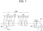
- the objective optical system includes in order from an object side, a first lens group G1 having a negative refractive power, a second lens group G2 having a positive refractive power, and a third lens group G3 having a positive refractive power. Moreover, an aperture stop S is disposed in the third lens group G3.
- the second lens group G2 moves toward an image side on an optical axis AX and corrects a change in a focal position due to a change from the normal observation state to the close observation state.
- the first lens group G1 includes a planoconcave negative lens L1, a plane-parallel plate L2, a biconcave negative lens L3, and a biconvex positive lens L4.
- the biconcave negative lens L3 and the biconvex positive lens L4 are cemented.
- the second lens group G2 includes a positive meniscus lens L5 having a convex surface directed toward the object side.
- the third lens group G3 includes a positive meniscus lens L6 having a convex surface directed toward the image side, a negative meniscus lens L7 having a convex surface directed toward the image side, an aperture stop S, a planoconvex positive lens L8, a biconvex positive lens L9, and a negative meniscus lens L10 having a convex surface directed toward the image side.
- the positive meniscus lens L6 and the negative meniscus lens L7 are cemented.
- the biconvex positive lens L9 and the negative meniscus lens L10 are cemented.
- An optical path splitting unit 20 is disposed on the image side of the third lens group G3. An optical path is bent in a prism in an optical system.
- the optical path splitting unit 20 will be described later.
- the plane-parallel plate L2 is a filter having a coating applied thereon for cutting light of a specific wavelength such as YAG (Yttrium Aluminum Garnet) laser of 1060 nm, semiconductor laser of 810 nm, or light of near-infrared region.
- Fig. 3A, Fig. 3B, Fig. 3C, and Fig. 3D show a spherical aberration (SA), an astigmatism (AS), a distortion (DT), and a chromatic aberration of magnification (CC) respectively in the normal observation state of the present example.
- SA spherical aberration
- AS astigmatism
- DT distortion
- CC chromatic aberration of magnification
- Fig. 3E, Fig. 3F, Fig. 3G, and Fig. 3H show a spherical aberration (SA), an astigmatism (AS), a distortion (DT), and a chromatic aberration of magnification (CC) respectively in the close observation state of the present example.
- SA spherical aberration
- AS astigmatism
- DT distortion
- CC chromatic aberration of magnification
- Fig. 4A and Fig. 4B are diagrams showing a cross-sectional arrangement of the objective optical system.
- Fig. 4A is a diagram showing a cross-sectional arrangement of the objective optical system in a normal observation state (an object point at a long distance)
- Fig. 4B is a diagram showing a cross-sectional arrangement of the objective optical system in a close observation state (an object point at a close distance).
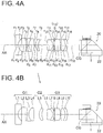
- the objective optical system includes in order from an object side, a first lens group G1 having a negative refractive power, a second lens group G2 having a positive refractive power, and a third lens group G3 having a positive refractive power. Moreover, an aperture stop S is disposed in the third lens group G3.
- the second lens group G2 moves toward an image side on an optical axis AX and corrects a change in a focal position due to a change from the normal observation state to the close observation state.
- the first lens group G1 includes a planoconcave negative lens L1, a plane-parallel plate L2, a biconcave negative lens L3, and a biconvex positive lens L4.
- the second lens group G2 includes a positive meniscus lens L5 having a convex surface directed toward the object side.
- the third lens group G3 includes a positive meniscus lens L6 having a convex surface directed toward the image side, a negative meniscus lens L7 having a convex surface directed toward the image side, an aperture stop S, a planoconvex positive lens L8, a biconvex positive lens L9, and a negative meniscus lens L10 having a convex surface directed toward the image side.
- the positive meniscus lens L6 and the negative meniscus lens L7 are cemented.
- the biconvex positive lens L9 and the negative meniscus lens L10 are cemented.
- An optical path splitting unit 20 is disposed on the image side of the third lens group G3. An optical path is bent in a prism in an optical system.
- the optical path splitting unit 20 will be described later.
- the plane-parallel plate L2 is a filter having a coating applied thereon for cutting light of a specific wavelength such as YAG laser of 1060 nm, semiconductor laser of 810 nm, or light of near-infrared region.
- Fig. 5A, Fig. 5B, Fig. 5C, and Fig. 5D show a spherical aberration (SA), an astigmatism (AS), a distortion (DT), and a chromatic aberration of magnification (CC) respectively in the normal observation state of the present example.
- SA spherical aberration
- AS astigmatism
- DT distortion
- CC chromatic aberration of magnification
- Fig. 5E, Fig. 5F, Fig. 5G, and Fig. 5H show a spherical aberration (SA), an astigmatism (AS), a distortion (DT), and a chromatic aberration of magnification (CC) respectively in the close observation state of the present example.
- SA spherical aberration
- AS astigmatism
- DT distortion
- CC chromatic aberration of magnification
- Fig. 6A and Fig. 6B are diagrams showing a cross-sectional arrangement of the objective optical system.
- Fig. 6A is a diagram showing a cross-sectional arrangement of the objective optical system in a normal observation state (an object point at a long distance)
- Fig. 6B is a diagram showing a cross-sectional arrangement of the objective optical system in a close observation state (an object point at a close distance).
- the objective optical system includes in order from an object side, a first lens group G1 having a negative refractive power, a second lens group G2 having a positive refractive power, and a third lens group G3 having a positive refractive power. Moreover, an aperture stop S is disposed in the third lens group G3.
- the second lens group G2 moves toward an image side on an optical axis AX and corrects a change in a focal position due to a change from the normal observation state to the close observation state.
- the first lens group G1 includes a planoconcave negative lens L1, a plane-parallel plate L2, a biconcave negative lens L3, and a biconvex positive lens L4.
- the biconcave negative lens L3 and the biconvex positive lens L4 are cemented.
- the second lens group G2 includes a positive meniscus lens L5 having a convex surface directed toward the object side.
- the third lens group G3 includes a positive meniscus lens L6 having a convex surface directed toward the image side, a negative meniscus lens L7 having a convex surface directed toward the image side, an aperture stop S, a biconvex positive lens L8, a biconvex positive lens L9, and a negative meniscus lens L10 having a convex surface directed toward the image side.
- the positive meniscus lens L6 and the negative meniscus lens L7 are cemented.
- the biconvex positive lens L9 and the negative meniscus lens L10 are cemented.
- An optical path splitting unit 20 is disposed on the image side of the third lens group G3. An optical path is bent in a prism in an optical system.
- the optical path splitting unit 20 will be described later.
- the plane-parallel plate L2 is a filter having a coating applied thereon for cutting light of a specific wavelength such as YAG laser of 1060 nm, semiconductor laser of 810 nm, or light of near-infrared region.
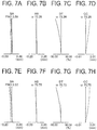
- Fig. 7A, Fig. 7B, Fig. 7C, and Fig. 7D show a spherical aberration (SA), an astigmatism (AS), a distortion (DT), and a chromatic aberration of magnification (CC) respectively in the normal observation state of the present example.
- SA spherical aberration
- AS astigmatism
- DT distortion
- CC chromatic aberration of magnification
- Fig. 7E, Fig. 7F, Fig. 7G, and Fig. 7H show a spherical aberration (SA), an astigmatism (AS), a distortion (DT), and a chromatic aberration of magnification (CC) respectively in the close observation state of the present example.
- SA spherical aberration
- AS astigmatism
- DT distortion
- CC chromatic aberration of magnification
- r denotes a radius of curvature of each lens surface
- d denotes a distance between two lens surfaces
- nd denotes a refractive index about a d-line of each lens
- vd denotes Abbe's number for each lens
- FNO denotes an F-number
- ⁇ denotes a half angle of view.
- Example3 (1) D_diff/im_pitch 3.333 25.000 100.000 (2) D_diff/R1_r 0.008 0.044 0.084 (3) D_diff/R1_f 0.000 0.000 0.000 (4) D_diff/FL_L01 -0.007 -0.039 -0.075 (5) D_diff/fw 0.0136 0.0702 0.1386 (6) D_diff/FB 0.003 0.014 0.031 (7) ⁇ (w)/ ⁇ (t) 1.019 1.024 1.015 Parameter Example1 Example2 Example3 D_diff 0.01 0.05 0.1 im_pitch 0.003 0.002 0.001 R1_r 1.2771 1.1482 1.1868 R1_f ⁇ ⁇ ⁇ FL_L01 -1.4379 -1.2928 -1.3363 fw 0.7328 0.7126 0.7214 FB 3.94 3.6196
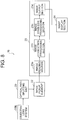
- Fig. 8 is a function block diagram of an endoscope system 10.
- Fig. 9 is a diagram showing a schematic arrangement of the optical path splitting unit 20.
- the optical path splitting unit 20 includes a polarization beam splitter 21 which splits an object image into two optical images of different focus, and an image pickup element 22 which acquires two images by capturing two optical images.
- the polarization beam splitter 21, as shown in Fig. 9 includes a first prism 21b, a second prism 21e, a mirror 21c, and a ⁇ /4 plate 21d. Both the first prism 21b and the second prism 21e have a beam-splitting surface which is inclined at 45 degrees with respect to an optical axis.
- a polarization splitting film 21f is formed on the beam splitting surface of the first prism 21b.
- the polarization beam splitter 21 is formed by letting the beam splitting surfaces of the first prism 21b and the second prism 21e respectively make a mutual contact via the polarization splitting film 21f.
- the mirror 21c is provided near an end surface of the first prism 21b via the ⁇ /4 plate 21d.
- the image pickup element 22 is attached to an end surface of the second prism 21e via a cover glass CG.
- An object image from the objective optical system OBL is split into a P-polarization component (light transmitted) and an S-polarization component (light reflected) by the polarization splitting film 21f provided to the beam splitting surface in the first prism 21b, and is split into two optical images namely an optical image on a side of the light reflected and an optical image on a side of the light transmitted.
- the optical image of the S-polarization component upon being reflected at the polarization splitting film 21f toward a side of a surface facing the image pickup element 22 follows an optical path A, and after being transmitted through the ⁇ /4 plate 21d, is reflected at the mirror 21c and returned toward the image pickup element 22.
- the optical image returned has an angle of polarization turned through 90° by being transmitted once again through the ⁇ /4 plate 21d, and is transmitted through the polarization splitting film 21f and is formed on the image pickup element 22.
- the optical image of the P-polarization component upon being transmitted through the polarization splitting film 21f, follows an optical path B, and is reflected by a mirror surface provided to a side facing the beam splitting surface of the second prism 21e that returns perpendicularly toward the image pickup element 22, and is formed on the image pickup element 22.
- path in prism glass is set to generate a predetermined optical path difference of a few tens of ⁇ m in the optical path A and the optical path B, and two optical images of different focus are formed on a light-receiving surface of the image pickup element 22.
- the first prism 21b and the second prism 21e are to be disposed such that, an optical path length on the side of the light reflected becomes short (small) with respect to an optical path length (path length in glass) on the side of the light transmitted reaching the image pickup element 22 in the first prism 21b in order to be able to split the object image into two optical images of different focusing positions.
- the image pickup element 22 as shown in Fig. 10 , is provided with two light-receiving areas (effective pixel areas) 22a and 22b in a total pixel area of the image pickup element 22 for receiving and capturing separately the two optical images of different focusing positions.
- the light-receiving areas 22a and 22b are disposed to coincide with image formation surfaces of these optical images respectively. Moreover, in the image pickup element 22, the focusing position of the light-receiving area 22a with respect to the light-receiving area 22b is shifted relatively toward a near-point side, and the focusing position of the light receiving area 22b with respect to the light-receiving area 22a is shifted relatively toward a far-point side. Accordingly, an arrangement is made to form two optical images of different focus on the light-receiving surface of the image pickup element 22.
- the optical path length reaching the image pickup element 22 may be changed, and the focusing positions for the light-receiving areas 22a and 22b may be shifted relatively.
- a correction pixel area 22c for correcting a geometrical shift of the optical image divided into two is provided around the light-receiving areas 22a and 22b.
- the second lens group G2 in each of the abovementioned examples is a focusing lens and can be moved selectively to two positions in a direction of an optical axis.
- the second lens group G2 is moved by an actuator which is not shown in the diagram to the two positions from one position to the other position and from the other position to the one position.
- the setting is to be carried out such that an object in an observation area, in a case of making a distant observation (normal observation) in a state in which the second lens group G2 is set at a front-side (object side) position, is in focus. Moreover, the setting is to be carried out such that an object in an observation area, in a case of making a close observation (magnifying observation) in a state in which the second lens group G2 is set at a rear-side position is in focus.
- a blood stream or mucosal structure of an object image is to be viewed comparatively closely in an endoscope in a large number of cases, and a possibility of an image becoming extremely complicated for a user is high.
- ⁇ /4 plate 21a on the object side of the optical path splitting unit 20 than the polarization splitting film 21f in order to restore the disturbed polarization state to the circularly-polarized light.
- a half mirror which splits intensity of light incident can also be used instead of the abovementioned polarization beam splitter.
- An image processor 23 includes an image reading section 23a which reads images related to the two optical images with different focusing positions captured by the image pickup element 22, the image correction processing section 23b which carries out image correction for two images read by the image reading section 23a, and an image synthesis processing section 23c which carries out image synthesis processing of combining the two images corrected.
- the image correction processing section 23b carries out correction of the images related to the two optical images formed in the light-receiving areas 22a and 22b respectively of the image pickup element 22 such that mutual differences other than the focus becomes substantially same for the two images.
- the image correction processing section 23b carries out correction of the two images such that relative position, angle, and magnification of each optical image of the two images are substantially same.
- the optical images formed on the light-receiving surfaces 22a and 22b respectively of the image pickup element 22 have a relative shift in magnification, shift in position, shift in angle, and shift in direction of rotation in some cases.
- the image synthesis processing section 23c in a corresponding predetermined area between the two images corrected by the image correction processing section 23b, selects an image with a relatively high contrast, and generates a composite image.
- the image synthesis processing section 23c compares the contrast in each of the spatially same pixel area in the two images, and by selecting a pixel area with relatively high contrast, generates a composite image as one image having the two images combined.
- An image output section 23d outputs an image subjected to the post-stage image processing.
- An image output from the image output section 23d is output to an image display section 24.
- the relative focusing positions may be let to be shifted by forming the first prism 21b and the second prism 21e of a different glass material depending on whether the optical path reaching the image pickup element is a near-point optical path or a far-point optical path, and letting the refractive indices to differ.
- images related to two optical images of different focus are acquired, and by combining these images by the image synthesis processing section 23c, it is possible to obtain a combined depth of field.
- the distant observation is suitable, and for observing details of a lesion, and diagnosis, the close observation is suitable.
- an image related to a far-point image and an image related to a near-point image of different focus acquired by the image pickup element 22 are subjected to correction processing of two near and far images in the image correction processing section 23b.
- correction parameters that have been set in advance correction of two images is carried out such that the relative positions, angles, and magnification of optical images of the two images become substantially same, and images, after being subjected to correction, are output to the image synthesis processing section 23c. A difference in brightness and color of the two images may be corrected if necessary.
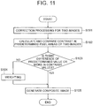
- step S102 the two images subjected to correction processing are combined in the image synthesis processing section 23c.
- contrast values for the pixel areas corresponding to the two near and far images respectively are calculated and compared.
- step S103 a judgement of whether or not there is a difference in the contrast values compared is made, and in a case in which there is a difference in the contrast values, the process advances to step S105, and the images are combined upon selecting an area of a high contrast value.
- the difference in the contrast values compared is small or the contrast values are almost same, as to which of the two near and far images is to be selected becomes a factor of uncertainty in processing. For instance, when there is a fluctuation of signal such as noise, there occurs a discontinuous area in the composite image, which leads to a trouble such as blurring of the object image which would have been resolved originally.
- step S104 in a case in which, the contrast values for the two images are almost same in the pixel areas for which the comparison of contrast has been carried out, the weighting is carried out, and the uncertainty of image selection is eliminated by carrying out an adding processing of image subjected to weighting at the subsequent step S105.
- the present embodiment in both the close observation and the distant observation, it is possible to acquire an image in which the depth of field is widened while preventing an occurrence of the discontinuous area in the composite image due to noise, and preventing the optical image from being blurred.
- the two images are captured by the same image pickup element, it is possible to reduce a manufacturing cost as compared to a case in which a plurality of image pickup elements is used, and to acquire an image in which the depth of field is widened without the apparatus becoming large.
- the desired depth of field is achieved and it is possible to prevent degradation of resolving power.
- any one of the images is formed as an image (mirror-image) shown in Fig. 12 , and an image processing of making a direction of images coincide by inverting the mirror-image in the image processor 23 is to be carried out.
- the image pickup element 22 has a shape which is long in a longitudinal direction of endoscope, it is preferable to rotate the composite image appropriately upon taking into consideration an aspect ratio of the image display section 24.
- the present invention is useful for an endoscope system in which, the depth of field is widened, and which is capable of achieving a high-quality image with an aberration corrected favorably.
Landscapes
- Physics & Mathematics (AREA)
- Health & Medical Sciences (AREA)
- Life Sciences & Earth Sciences (AREA)
- Optics & Photonics (AREA)
- Surgery (AREA)
- Engineering & Computer Science (AREA)
- General Physics & Mathematics (AREA)
- General Health & Medical Sciences (AREA)
- Radiology & Medical Imaging (AREA)
- Medical Informatics (AREA)
- Heart & Thoracic Surgery (AREA)
- Pathology (AREA)
- Molecular Biology (AREA)
- Animal Behavior & Ethology (AREA)
- Nuclear Medicine, Radiotherapy & Molecular Imaging (AREA)
- Public Health (AREA)
- Veterinary Medicine (AREA)
- Biomedical Technology (AREA)
- Biophysics (AREA)
- Astronomy & Astrophysics (AREA)
- Multimedia (AREA)
- Signal Processing (AREA)
- Lenses (AREA)
- Endoscopes (AREA)
- Instruments For Viewing The Inside Of Hollow Bodies (AREA)
- Studio Devices (AREA)
- Optical Elements Other Than Lenses (AREA)
Abstract


D_diff denotes an air conversion length of a difference in length of optical paths of the two optical images,
im_pitch denotes a pixel pitch of the image pickup element, and
R1_r denotes a radius of curvature at an image-side surface of the first lens having a negative refractive power.
Description
- The present invention relates to an endoscope system, and particularly to a depth-of-field endoscope system.
- Generally, in equipment provided with an image pickup element, such as an endoscope system, a depth of field has been known to become narrow with the number of pixels of the image pickup element becoming large. In other words, in an image pickup element, when a pixel pitch (horizontal and vertical dimensions of one pixel) is made small, since a permissible circle of confusion becomes small with the pixel pitch made small, the depth of field of an image pickup apparatus becomes narrow.
- For widening the depth of field, in patent literature 1 for example, an arrangement in which, images are formed by splitting a self-image, and the images acquired are combined by image processing and the depth is widened has been disclosed. Moreover, in patent literature 2, an arrangement in which, images are formed by dividing a self-portrait, and the images acquired are combined by image processing and the depth is widened has been disclosed. In this arrangement, since it is possible to acquire images by using one image pickup element, it is outstanding from a cost point of view.
-
- Patent literature 1: Japanese Patent Publication No.
4226235 - Patent literature 2: Japanese Patent Publication No.
5593004 - In an arrangement according to patent literature 1, since a plurality of image pickup elements necessary, the cost becomes excessively high and therefore it is not preferable. Moreover, in an arrangement according to patent literature 2, optimum condition of an objective optical system for an image of a central area and a peripheral area has not been regulated. Therefore, aberration is not corrected adequately from the central area up to the peripheral area, and sometimes it is difficult to achieve a favorable image.
- The present invention has been made in view of such issues, and an object of the present invention is to provide an endoscope system in which the depth of field is widened, and which is capable of acquiring a high-quality image with an aberration corrected favorably.
- To solve the abovementioned issues, and to achieve the object, the present invention provides the following means.
- An endoscope system according to an aspect of the present invention includes
an objective optical system,
an optical path splitting unit which splits an object image acquired by the objective optical system into two optical images of a different focus,
an image pickup element which acquires the optical images, and
an image synthesis processing section which selects in a predetermined area, an image with a relatively high contrast out of the two optical images acquired, and generates a composite image, wherein
the objective optical system includes a first lens having a negative refractive power which is nearest to object, and
the endoscope system satisfies the following conditional expressions (1) and (2).

- D_diff denotes an air conversion length of a difference in length of optical paths of the two optical images,
- im_pitch denotes a pixel pitch of the image pickup element, and
- R1_r denotes a radius of curvature at an image-side surface of the first lens having a negative refractive power.
- An endoscope system according to an embodiment of the present invention shows an effect that it is possible to achieve a high-quality image with an aberration corrected favorably, and the depth of field widened.
-
-
Fig. 1 is a diagram showing a cross-sectional arrangement of an objective optical system, an optical path splitting unit, and an image pickup element in an endoscope system according to an embodiment of the present invention; -
Fig. 2A and Fig. 2B are diagrams showing a cross-sectional arrangement of an objective optical system, an optical path splitting unit, and an image pickup element in an endoscope system according to an example 1 of the present invention, where,Fig. 2A is a cross-sectional view in a normal observation state andFig. 2B is a cross-sectional view in a close observation state; -
Fig. 3A, Fig. 3B, Fig. 3C, and Fig. 3D are aberration diagrams showing a spherical aberration (SA), an astigmatism (AS), a distortion (DT), and a chromatic aberration of magnification (CC) respectively in the normal observation state of the example 1, andFig. 3E, Fig. 3F, Fig. 3G, and Fig. 3H are aberration diagrams showing a spherical aberration (SA), an astigmatism (AS), a distortion (DT), and a chromatic aberration of magnification (CC) respectively in the close observation state of the example 1; -
Fig. 4A and Fig. 4B are diagrams showing a cross-sectional arrangement of an objective optical system, an optical path splitting unit, and an image pickup element in an endoscope system according to an example 2 of the present invention, where,Fig. 4A is a cross-sectional view in a normal observation state andFig. 4B is a cross-sectional view in a close observation state; -
Fig. 5A, Fig. 5B, Fig. 5C, and Fig. 5D are aberration diagrams showing a spherical aberration (SA), an astigmatism (AS), a distortion (DT), and a chromatic aberration of magnification (CC) respectively in the normal observation state of the example 2, andFig. 5E, Fig. 5F, Fig. 5G, and Fig. 5H are aberration diagrams showing a spherical aberration (SA), an astigmatism (AS), a distortion (DT), and a chromatic aberration of magnification (CC) respectively in the close observation state of the example 2; -
Fig. 6A and Fig. 6B are diagrams showing a cross-sectional arrangement of an objective optical system, an optical path splitting unit, and an image pickup element in an endoscope system according to an example 3 of the present invention, where,Fig. 6A is a cross-sectional view in a normal observation state andFig. 6B is a cross-sectional view in a close observation state; -
Fig. 7A, Fig. 7B, Fig. 7C, and Fig. 7D are aberration diagrams showing a spherical aberration (SA), an astigmatism (AS), a distortion (DT), and a chromatic aberration of magnification (CC) respectively in the normal observation state of the example 3, andFig. 7E, Fig. 7F, Fig. 7G, and Fig. 7H are aberration diagrams showing a spherical aberration (SA), an astigmatism (AS), a distortion (DT), and a chromatic aberration of magnification (CC) respectively in the close observation state of the example 3; -
Fig. 8 is a functional block diagram showing a configuration of an endoscope system according to an embodiment of the present invention; -
Fig. 9 is a schematic block diagram of an optical path splitting unit and an image pickup element in the endoscope system according to the embodiment of the present invention; -
Fig. 10 is a schematic block diagram of the image pickup element in the endoscope system according to the embodiment of the present invention; -
Fig. 11 is a flowchart showing a flow in a case of combining two optical images in the endoscope system according to the embodiment of the present invention; and -
Fig. 12 is a diagram showing an image formation state when an image is formed on the image pickup element after odd number of reflections by a beam splitter in the endoscope system according to the embodiment of the present invention. - Reasons for adopting such arrangements and effects thereof in an endoscope system according to the present embodiment will be described below by referring to the accompanying diagrams. However, the present invention is not limited to the embodiments described below.
- The endoscope system according to the present embodiment includes an objective optical system, an optical path splitting unit which splits an object image acquired by the objective optical system into two optical images of a different focus; an image pickup element which acquires the optical images, and an image synthesis processing section which selects in a predetermined area, an image with a relatively high contrast from the two optical images acquired, and generates a composite image, wherein the objective optical system includes a first lens having a negative refractive power which is nearest to object, and the endoscope system satisfies the following conditional expressions (1) and (2).


- D_diff denotes an air conversion length of a difference in length of optical paths of the two optical images,
- im_pitch denotes a pixel pitch of the image pickup element, and
- R1_r denotes a radius of curvature at an image-side surface of the first lens having a negative refractive power.
- By acquiring two optical images of different focus and generating a composite image, it is possible to achieve an image with a wide depth of field. For splitting an optical path, it is necessary to dispose an optical member such as a prism unit. Therefore, it is necessary to make a distance (FB) from a rearmost surface of the objective optical system up to an image forming position longer than that in a normal optical system.
- By using a lens having a negative refractive power for the first lens of the objective optical system, since it is possible to achieve a long FB with lesser number of lenses, it is preferable.
- Conditional expression (1) regulates an appropriate focus difference of two optical images with different focus. When conditional expression (1) is satisfied, it is possible to maintain the appropriate focus difference. Consequently, it is possible to acquire a favorable image while widening the depth of field.
- When an upper limit value of conditional expression (1) is exceeded, the focus difference in the two optical images becomes excessively large. Consequently, even when a composite image of two optical images is generated, since an object distance at which the image is out of focus exists, it is not preferable.
- When a value falls below a lower limit value of conditional expression (1), the focus difference in the two optical images becomes excessively small. Consequently, since an effect of widening the depth of field is diminished, it is not preferable.
- Conditional expression (2) regulates an appropriate relationship of the focus difference in the two optical images and the first lens having a negative refractive power.
- When an upper limit value of conditional expression (2) is exceeded, an amount of an off-axis aberration that occurs in the first lens having a negative refractive power becomes large. Consequently, since an image quality is degraded in a periphery of image, it is not preferable.
- When a value falls below a lower limit value of conditional expression (2), the power (refractive power) of the first lens having a negative refractive power becomes small. Consequently, it is not possible to achieve the necessary FB, and therefore it is not preferable.
- It is desirable to satisfy the following conditional expression (1)' instead of conditional expression (1).

- Furthermore, it is more desirable to satisfy the following conditional expression (1)" instead of conditional expression (1).

- It is desirable to satisfy the following conditional expression (2)' instead of conditional expression (2).

- Furthermore, it is more desirable to satisfy the following conditional expression (2") instead of conditional expression (2).

- Moreover, according to a preferable aspect of the present invention, it is desirable to satisfy the following conditional expressions (3) and (4).


- D_diff denotes the air conversion length of the difference in length of optical paths of the two optical images,
- R1_f denotes a radius of curvature at an object-side surface of the first lens having a negative refractive power, and
- FL_L01 denotes a focal length of the first lens at e-line.
- Conditional expressions (3) and (4) regulate an appropriate relationship of the focus difference of the two optical images respectively, and the first lens having a negative refractive power.
- When either an upper limit value of conditional expression (3) is exceeded or a value falls below a lower limit value of conditional expression (3), the radius of curvature of a first surface of the lens becomes excessively small, and water removal is degraded. Accordingly, since an image becomes such that the focus is partially blurred where water droplets are accumulated, it is not preferable.
- When a value falls below a lower limit value of conditional expression (4), an amount of an off-axis aberration that occurs in the first lens having a negative refractive power becomes large. Consequently, since an image quality is degraded in a peripheral area, it is not preferable.
- When an upper limit value of conditional expression (4) is exceeded, the power of the first lens having a negative refractive power becomes excessively small. Consequently, since it is not possible to achieve the necessary FB, it is not preferable.
- It is desirable to satisfy the following conditional expression (3)' instead of conditional expression (3).

- Furthermore, it is more desirable to satisfy the following conditional expression (3)" instead of conditional expression (3).

- It is desirable to satisfy the following conditional expression (4)' instead of conditional expression (4).

- Furthermore, it is more desirable to satisfy the following conditional expression (4)" instead of conditional expression (4).

- Moreover, according to a preferable aspect of the present invention, it is desirable to satisfy the following conditional expressions (5) and (6).


- D_diff denotes the air conversion length of a difference in length of optical paths of the two optical images,
- fw denotes a focal length of the objective optical system, and
- FB denotes an air conversion length from a rearmost lens of the objective optical system up to an image forming position.
- Conditional expression (5) regulates an appropriate relationship of the focus difference in the two optical images of different focus and the focal length of the objective optical system.
- When conditional expression (5) is satisfied, the two images have the appropriate focus difference. Consequently, it is possible to achieve a favorable image while widening the depth of field.
- When an upper limit value of conditional expression (5) is exceeded, the focus difference in the two images becomes excessively large. Accordingly, even when a composite image of two optical images is generated, since a distance of an object at which the focus is blurred exists, it is not preferable.
- When a value falls below a lower limit value of conditional expression (5), the focus difference in the two images becomes excessively small. Accordingly, since an effect of widening the depth of field is small, it is not preferable.
- Conditional expression (6) regulates an appropriate ratio of the focus difference of the optical images and FB.
- When an upper limit value of conditional expression (6) is exceeded, FB becomes excessively short. Consequently, since there is no space for disposing an optical element that splits an optical path, it is not preferable.
- When a value falls below a lower limit value of conditional expression (6), FB becomes remarkably and excessively long. As a result, it is necessary to make the refractive power of the first lens remarkably large, and since mainly an off-axis aberration occurs, it is not preferable.
- It is desirable to satisfy the following conditional expression (5)' instead of conditional expression (5).

- Furthermore, it is more desirable to satisfy the following conditional expression (5)" instead of conditional expression (5).

- It is desirable to satisfy the following conditional expression (6)' instead of conditional expression (6).

- Furthermore, it is more desirable to satisfy the following conditional expression (6)" instead of conditional expression (6).

- Moreover, according to a preferable aspect of the present invention, it is desirable that the objective optical system enables normal observation and close observation by driving a lens at an interior of the objective optical system, and satisfies the following conditional expression (7).

- ω(w) denotes a half angle of view at the time of normal observation of the objective optical system, and
- ω(t) denotes a half angle of view at the time of close observation of the objective optical system.
- Conditional expression (7) regulates an appropriate ratio of a change in an angle of view of the objective optical system.
- When the objective optical system satisfies conditional expression (7), in the two optical images of different focus, the normal observation and the close observation are possible even while widening the depth of field. Particularly, since the magnification becomes large in the close observation, the depth of field tends to become small. Here, by using an image synthesis technology that will be described later, in the close observation, it is possible to make the depth of field small.
- When a value falls below a lower limit value of conditional expression (7), the close observation is not possible. Consequently, the technology as in the present embodiment is not necessary.
- When an upper limit value of conditional expression (7) is exceeded, the change in the angle of view becomes excessively large. Consequently, a lens diameter is enlarged, and a QOL (Quality Of Life) of patient is degraded, and therefore it is not preferable.
- It is desirable to satisfy the following conditional expression (7)' instead of conditional expression (7).

- Furthermore, it is more desirable to satisfy the following conditional expression (7)" instead of conditional expression (7).

- Next, an objective optical system in an endoscope system according to an example 1 of the present invention will be described below.
-
Fig. 2A and Fig. 2B are diagrams showing a cross-sectional arrangement of the objective optical system. Here,Fig. 2A is a diagram showing a cross-sectional arrangement of the objective optical system in a normal observation state (an object point at a long distance), andFig. 2B is a diagram showing a cross-sectional arrangement of the objective optical system in a close observation state (an object point at a close distance). - The objective optical system according to the present example includes in order from an object side, a first lens group G1 having a negative refractive power, a second lens group G2 having a positive refractive power, and a third lens group G3 having a positive refractive power. Moreover, an aperture stop S is disposed in the third lens group G3. The second lens group G2 moves toward an image side on an optical axis AX and corrects a change in a focal position due to a change from the normal observation state to the close observation state.
- The first lens group G1 includes a planoconcave negative lens L1, a plane-parallel plate L2, a biconcave negative lens L3, and a biconvex positive lens L4. Here, the biconcave negative lens L3 and the biconvex positive lens L4 are cemented.
- The second lens group G2 includes a positive meniscus lens L5 having a convex surface directed toward the object side.
- The third lens group G3 includes a positive meniscus lens L6 having a convex surface directed toward the image side, a negative meniscus lens L7 having a convex surface directed toward the image side, an aperture stop S, a planoconvex positive lens L8, a biconvex positive lens L9, and a negative meniscus lens L10 having a convex surface directed toward the image side. Here, the positive meniscus lens L6 and the negative meniscus lens L7 are cemented. The biconvex positive lens L9 and the negative meniscus lens L10 are cemented.
- An optical
path splitting unit 20 is disposed on the image side of the third lens group G3. An optical path is bent in a prism in an optical system. The opticalpath splitting unit 20 will be described later. The plane-parallel plate L2 is a filter having a coating applied thereon for cutting light of a specific wavelength such as YAG (Yttrium Aluminum Garnet) laser of 1060 nm, semiconductor laser of 810 nm, or light of near-infrared region. -
Fig. 3A, Fig. 3B, Fig. 3C, and Fig. 3D show a spherical aberration (SA), an astigmatism (AS), a distortion (DT), and a chromatic aberration of magnification (CC) respectively in the normal observation state of the present example. -
Fig. 3E, Fig. 3F, Fig. 3G, and Fig. 3H show a spherical aberration (SA), an astigmatism (AS), a distortion (DT), and a chromatic aberration of magnification (CC) respectively in the close observation state of the present example. - These various aberration diagrams show aberrations at wavelengths of 656.27 nm (C-line), 587.56 nm (d-line), and 435. 84 nm (g-line). Moreover, in each diagram, ω denotes a half angle of view. Similar is the case for aberration diagrams described below.
- An objective optical system in an endoscope system according to an example 2 of the present invention will be described below.
-
Fig. 4A and Fig. 4B are diagrams showing a cross-sectional arrangement of the objective optical system. Here,Fig. 4A is a diagram showing a cross-sectional arrangement of the objective optical system in a normal observation state (an object point at a long distance), andFig. 4B is a diagram showing a cross-sectional arrangement of the objective optical system in a close observation state (an object point at a close distance). - The objective optical system according to the present example includes in order from an object side, a first lens group G1 having a negative refractive power, a second lens group G2 having a positive refractive power, and a third lens group G3 having a positive refractive power. Moreover, an aperture stop S is disposed in the third lens group G3. The second lens group G2 moves toward an image side on an optical axis AX and corrects a change in a focal position due to a change from the normal observation state to the close observation state.
- The first lens group G1 includes a planoconcave negative lens L1, a plane-parallel plate L2, a biconcave negative lens L3, and a biconvex positive lens L4.
- The second lens group G2 includes a positive meniscus lens L5 having a convex surface directed toward the object side.
- The third lens group G3 includes a positive meniscus lens L6 having a convex surface directed toward the image side, a negative meniscus lens L7 having a convex surface directed toward the image side, an aperture stop S, a planoconvex positive lens L8, a biconvex positive lens L9, and a negative meniscus lens L10 having a convex surface directed toward the image side. Here, the positive meniscus lens L6 and the negative meniscus lens L7 are cemented. The biconvex positive lens L9 and the negative meniscus lens L10 are cemented.
- An optical
path splitting unit 20 is disposed on the image side of the third lens group G3. An optical path is bent in a prism in an optical system. The opticalpath splitting unit 20 will be described later. The plane-parallel plate L2 is a filter having a coating applied thereon for cutting light of a specific wavelength such as YAG laser of 1060 nm, semiconductor laser of 810 nm, or light of near-infrared region. -
Fig. 5A, Fig. 5B, Fig. 5C, and Fig. 5D show a spherical aberration (SA), an astigmatism (AS), a distortion (DT), and a chromatic aberration of magnification (CC) respectively in the normal observation state of the present example. -
Fig. 5E, Fig. 5F, Fig. 5G, and Fig. 5H show a spherical aberration (SA), an astigmatism (AS), a distortion (DT), and a chromatic aberration of magnification (CC) respectively in the close observation state of the present example. - An objective optical system in an endoscope system according to an example 3 of the present invention will be described below.
-
Fig. 6A and Fig. 6B are diagrams showing a cross-sectional arrangement of the objective optical system. Here,Fig. 6A is a diagram showing a cross-sectional arrangement of the objective optical system in a normal observation state (an object point at a long distance), andFig. 6B is a diagram showing a cross-sectional arrangement of the objective optical system in a close observation state (an object point at a close distance). - The objective optical system according to the present example includes in order from an object side, a first lens group G1 having a negative refractive power, a second lens group G2 having a positive refractive power, and a third lens group G3 having a positive refractive power. Moreover, an aperture stop S is disposed in the third lens group G3. The second lens group G2 moves toward an image side on an optical axis AX and corrects a change in a focal position due to a change from the normal observation state to the close observation state.
- The first lens group G1 includes a planoconcave negative lens L1, a plane-parallel plate L2, a biconcave negative lens L3, and a biconvex positive lens L4. Here, the biconcave negative lens L3 and the biconvex positive lens L4 are cemented.
- The second lens group G2 includes a positive meniscus lens L5 having a convex surface directed toward the object side.
- The third lens group G3 includes a positive meniscus lens L6 having a convex surface directed toward the image side, a negative meniscus lens L7 having a convex surface directed toward the image side, an aperture stop S, a biconvex positive lens L8, a biconvex positive lens L9, and a negative meniscus lens L10 having a convex surface directed toward the image side. Here, the positive meniscus lens L6 and the negative meniscus lens L7 are cemented. The biconvex positive lens L9 and the negative meniscus lens L10 are cemented.
- An optical
path splitting unit 20 is disposed on the image side of the third lens group G3. An optical path is bent in a prism in an optical system. The opticalpath splitting unit 20 will be described later. The plane-parallel plate L2 is a filter having a coating applied thereon for cutting light of a specific wavelength such as YAG laser of 1060 nm, semiconductor laser of 810 nm, or light of near-infrared region. -
Fig. 7A, Fig. 7B, Fig. 7C, and Fig. 7D show a spherical aberration (SA), an astigmatism (AS), a distortion (DT), and a chromatic aberration of magnification (CC) respectively in the normal observation state of the present example. -
Fig. 7E, Fig. 7F, Fig. 7G, and Fig. 7H show a spherical aberration (SA), an astigmatism (AS), a distortion (DT), and a chromatic aberration of magnification (CC) respectively in the close observation state of the present example. - Numerical data for each example is shown below. Regarding symbols, r denotes a radius of curvature of each lens surface, d denotes a distance between two lens surfaces, nd denotes a refractive index about a d-line of each lens, vd denotes Abbe's number for each lens, FNO denotes an F-number, and ω denotes a half angle of view.
-
Surface data Surface no. r d nd vd 1 ∞ 0.44 1.88300 40.76 2 1.277 0.62 3 ∞ 0.66 1.51800 75.00 4 ∞ 0.15 5 -3.765 0.22 1.88300 40.76 6 1.867 0.95 1.84666 23.78 7 -5.648 Variable 8 1.479 0.44 1.48749 70.23 9 1.634 Variable 10 -3.521 0.90 1.64769 33.79 11 -0.998 0.22 1.88300 40.76 12 -2.573 0.06 13 (Stop) ∞ 0.00 14 ∞ 0.93 1.48749 70.23 15 -2.659 0.06 16 5.794 0.67 1.48749 70.23 17 -1.567 0.33 1.92286 18.90 18 -2.318 3.94 19 (Imaging surface) ∞ Zoom data Normal observation state Close observation state focal length 0.73 0.73 Fno. 3.58 3.52 Angle of view 2ω 136.30 133.76 d7 0.22 1.12 d9 1.78 0.88 Group focal length f1=-1.29 f2=16.55 f3=2.51 -
Surface data Surface no. r d nd vd 1 ∞ 0.41 1.88300 40.76 2 1.148 0.52 3 ∞ 0.62 1.00000 65.13 4 ∞ 0.21 5 -5.040 0.21 1.88300 40.76 6 1.370 0.78 1.84666 23.78 7 -10.799 Variable 8 1.394 0.41 1.48749 70.23 9 1.623 Variable 10 -4.845 0.83 1.64769 33.79 11 -0.940 0.21 1.88300 40.76 12 -2.618 0.06 13 (Stop) ∞ 0.00 14 ∞ 0.87 1.48749 70.23 15 -2.246 0.06 16 5.696 0.67 1.48749 70.23 17 -1.477 0.31 1.92286 18.90 18 -2.201 3.62 19(Imaging surface) ∞ Zoom data Normal observation state Close observation state focal length 0.71 0.71 Fno. 3.54 3.49 Angle of view 2ω 144.97 141.76 d7 0.21 0.75 d9 1.32 0.78 Group focal length f1=-1.05 f2=12.66 f3=2.30 -
Surface data Surface no. r d nd vd 1 ∞ 0.41 1.88300 40.76 2 1.187 0.52 3 ∞ 0.60 1.51800 75.00 4 ∞ 0.13 5 -10.716 0.42 1.88300 40.76 6 1.435 0.79 1.84666 23.78 7 -25.907 Variable 8 1.280 0.52 1.48749 70.23 9 1.504 Variable 10 -6.016 0.91 1.64769 33.79 11 -0.915 0.31 1.88300 40.76 12 -3.148 0.06 13 (Stop) ∞ 0.00 14 43.657 1.00 1.48749 70.23 15 -2.302 0.03 16 3.834 0.91 1.48749 70.23 17 -1.454 0.31 1.92286 18.90 18 -2.191 3.22 19 (Imaging surface) ∞ Zoom data Normal observation state Close observation state focal length 0.72 0.72 Fno. 3.58 3.52 Angle of view 2ω 144.52 141.51 d7 0.26 0.79 d9 1.08 0.55 Group focal length fl=-1.16 f2=10.01 f3=2.21 - Values of the conditional expressions (1) to (7) of example 1, example 2 and example 3 are shown below.
Conditional Expression Example1 Example2 Example3 (1) D_diff/im_pitch 3.333 25.000 100.000 (2) D_diff/R1_r 0.008 0.044 0.084 (3) D_diff/R1_f 0.000 0.000 0.000 (4) D_diff/FL_L01 -0.007 -0.039 -0.075 (5) D_diff/fw 0.0136 0.0702 0.1386 (6) D_diff/FB 0.003 0.014 0.031 (7) ω(w)/ω(t) 1.019 1.024 1.015 Parameter Example1 Example2 Example3 D_diff 0.01 0.05 0.1 im_pitch 0.003 0.002 0.001 R1_r 1.2771 1.1482 1.1868 R1_f ∞ ∞ ∞ FL_L01 -1.4379 -1.2928 -1.3363 fw 0.7328 0.7126 0.7214 FB 3.94 3.6196 3.225 ω(w) 68.558 73.325 63.371 ω(t) 67.26 71.638 62.406 - Next, an endoscope system which includes the abovementioned objective optical system will be described below.
-
Fig. 8 is a function block diagram of anendoscope system 10.Fig. 9 is a diagram showing a schematic arrangement of the opticalpath splitting unit 20. - Light emerged from an objective optical system OBL of each of the abovementioned example is incident on the optical
path splitting unit 20. - The optical
path splitting unit 20 includes apolarization beam splitter 21 which splits an object image into two optical images of different focus, and animage pickup element 22 which acquires two images by capturing two optical images. - The
polarization beam splitter 21, as shown inFig. 9 , includes afirst prism 21b, asecond prism 21e, amirror 21c, and a λ/4plate 21d. Both thefirst prism 21b and thesecond prism 21e have a beam-splitting surface which is inclined at 45 degrees with respect to an optical axis. - A
polarization splitting film 21f is formed on the beam splitting surface of thefirst prism 21b. Thepolarization beam splitter 21 is formed by letting the beam splitting surfaces of thefirst prism 21b and thesecond prism 21e respectively make a mutual contact via thepolarization splitting film 21f. - Moreover, the
mirror 21c is provided near an end surface of thefirst prism 21b via the λ/4plate 21d. Theimage pickup element 22 is attached to an end surface of thesecond prism 21e via a cover glass CG. - An object image from the objective optical system OBL is split into a P-polarization component (light transmitted) and an S-polarization component (light reflected) by the
polarization splitting film 21f provided to the beam splitting surface in thefirst prism 21b, and is split into two optical images namely an optical image on a side of the light reflected and an optical image on a side of the light transmitted. - The optical image of the S-polarization component, upon being reflected at the
polarization splitting film 21f toward a side of a surface facing theimage pickup element 22 follows an optical path A, and after being transmitted through the λ/4plate 21d, is reflected at themirror 21c and returned toward theimage pickup element 22. The optical image returned has an angle of polarization turned through 90° by being transmitted once again through the λ/4plate 21d, and is transmitted through thepolarization splitting film 21f and is formed on theimage pickup element 22. - The optical image of the P-polarization component, upon being transmitted through the
polarization splitting film 21f, follows an optical path B, and is reflected by a mirror surface provided to a side facing the beam splitting surface of thesecond prism 21e that returns perpendicularly toward theimage pickup element 22, and is formed on theimage pickup element 22. At this time, path in prism glass is set to generate a predetermined optical path difference of a few tens of µm in the optical path A and the optical path B, and two optical images of different focus are formed on a light-receiving surface of theimage pickup element 22. - In other words, the
first prism 21b and thesecond prism 21e are to be disposed such that, an optical path length on the side of the light reflected becomes short (small) with respect to an optical path length (path length in glass) on the side of the light transmitted reaching theimage pickup element 22 in thefirst prism 21b in order to be able to split the object image into two optical images of different focusing positions. - The
image pickup element 22, as shown inFig. 10 , is provided with two light-receiving areas (effective pixel areas) 22a and 22b in a total pixel area of theimage pickup element 22 for receiving and capturing separately the two optical images of different focusing positions. - The light-receiving
areas image pickup element 22, the focusing position of the light-receivingarea 22a with respect to the light-receivingarea 22b is shifted relatively toward a near-point side, and the focusing position of thelight receiving area 22b with respect to the light-receivingarea 22a is shifted relatively toward a far-point side. Accordingly, an arrangement is made to form two optical images of different focus on the light-receiving surface of theimage pickup element 22. - By letting a refractive index of glass materials of the
first prism 21b and thesecond prism 21e to be different, the optical path length reaching theimage pickup element 22 may be changed, and the focusing positions for the light-receivingareas - Moreover, a
correction pixel area 22c for correcting a geometrical shift of the optical image divided into two is provided around the light-receivingareas correction pixel area 22c, and carrying out the correction by image processing in an imagecorrection processing section 23b (Fig. 8 ) that will be described later, the geometrical shift of the optical image is eliminated. - The second lens group G2 in each of the abovementioned examples is a focusing lens and can be moved selectively to two positions in a direction of an optical axis. The second lens group G2 is moved by an actuator which is not shown in the diagram to the two positions from one position to the other position and from the other position to the one position.
- The setting is to be carried out such that an object in an observation area, in a case of making a distant observation (normal observation) in a state in which the second lens group G2 is set at a front-side (object side) position, is in focus. Moreover, the setting is to be carried out such that an object in an observation area, in a case of making a close observation (magnifying observation) in a state in which the second lens group G2 is set at a rear-side position is in focus.
- As in the present embodiment, in a case of carrying out polarization splitting by using the
polarization beam splitter 21, when a polarization state of light to be split is not circularly-polarized light, there arises a difference in brightness of images split. Correction of an orderly difference in brightness by image processing is comparatively easy, but when the difference in brightness arises locally and according to observation conditions, it cannot be corrected fully, and in some cases, this leads to an unevenness in brightness in a composite image. - For an object to be observed by an endoscope, there is a possibility of unevenness in brightness in a comparatively peripheral portion of the field of view of the composite image. This unevenness in brightness due to a disrupted polarization state appears remarkably when the object has a brightness distribution that tends to be saturated comparatively.
- In the peripheral portion of the field of view, a blood stream or mucosal structure of an object image is to be viewed comparatively closely in an endoscope in a large number of cases, and a possibility of an image becoming extremely complicated for a user is high.
- Therefore, as shown in
Fig. 9 for instance, it is preferable to dispose the λ/4plate 21a on the object side of the opticalpath splitting unit 20 than thepolarization splitting film 21f in order to restore the disturbed polarization state to the circularly-polarized light. - A half mirror which splits intensity of light incident can also be used instead of the abovementioned polarization beam splitter.
- Next, a combining of two images acquired will be described below by referring to
Fig. 8 . - An
image processor 23 includes animage reading section 23a which reads images related to the two optical images with different focusing positions captured by theimage pickup element 22, the imagecorrection processing section 23b which carries out image correction for two images read by theimage reading section 23a, and an imagesynthesis processing section 23c which carries out image synthesis processing of combining the two images corrected. - The image
correction processing section 23b carries out correction of the images related to the two optical images formed in the light-receivingareas image pickup element 22 such that mutual differences other than the focus becomes substantially same for the two images. In other words, the imagecorrection processing section 23b carries out correction of the two images such that relative position, angle, and magnification of each optical image of the two images are substantially same. - In a case of splitting the object image into two and forming each image on the
image pickup element 22, a geometrical difference is generated in some cases. In other words, the optical images formed on the light-receivingsurfaces image pickup element 22 have a relative shift in magnification, shift in position, shift in angle, and shift in direction of rotation in some cases. - It is difficult to completely eliminate these differences at the time of manufacturing, and when an amount of shift becomes large, the composite image becomes a double image giving rise to unusual unevenness in brightness. Therefore, the abovementioned geometrical difference and difference in brightness are to be corrected in the image
correction processing section 23b. - In a case of correcting the difference in brightness between the two images, it is desirable to carry out the correction with reference to an image or a screen image having a low luminance out of the two images or screen images, or an image or a screen image having a low luminance at relatively same position out of the two images or screen images.
- The image
synthesis processing section 23c, in a corresponding predetermined area between the two images corrected by the imagecorrection processing section 23b, selects an image with a relatively high contrast, and generates a composite image. In other words, the imagesynthesis processing section 23c compares the contrast in each of the spatially same pixel area in the two images, and by selecting a pixel area with relatively high contrast, generates a composite image as one image having the two images combined. - In a case in which, a difference in contrast in the same pixel area of the two images is small or the contrast is substantially same, by a synthesis image processing of calculating upon predetermined weighting of that pixel area, a composite image is generated.
- Moreover, the
image processor 23, for one image combined by the imagesynthesis processing section 23c, carries out a post-stage image processing such as a color matrix processing, an outline enhancement, and a gamma correction processing. Animage output section 23d outputs an image subjected to the post-stage image processing. An image output from theimage output section 23d is output to animage display section 24. - Moreover, the relative focusing positions may be let to be shifted by forming the
first prism 21b and thesecond prism 21e of a different glass material depending on whether the optical path reaching the image pickup element is a near-point optical path or a far-point optical path, and letting the refractive indices to differ. - Accordingly, images related to two optical images of different focus are acquired, and by combining these images by the image
synthesis processing section 23c, it is possible to obtain a combined depth of field. For screening upon taking a long shot of a wide range in endoscopy, the distant observation is suitable, and for observing details of a lesion, and diagnosis, the close observation is suitable. - By adopting such an arrangement, it is possible to widen the depth of field without letting the resolving power to be degraded even when an image pickup element with even larger number of pixels is used. Furthermore, since there is a focusing mechanism, it is possible to carry out endoscopic observation with a high-quality image by switching the range of observation flexibly, and diagnosis.
- Next, a flow in a case of combining the two optical images in the present embodiment will be described below while referring to a flowchart in
Fig. 11 . - At step S101, an image related to a far-point image and an image related to a near-point image of different focus acquired by the
image pickup element 22 are subjected to correction processing of two near and far images in the imagecorrection processing section 23b. In other words, according to correction parameters that have been set in advance, correction of two images is carried out such that the relative positions, angles, and magnification of optical images of the two images become substantially same, and images, after being subjected to correction, are output to the imagesynthesis processing section 23c. A difference in brightness and color of the two images may be corrected if necessary. - At step S102, the two images subjected to correction processing are combined in the image
synthesis processing section 23c. At this time, contrast values for the pixel areas corresponding to the two near and far images respectively are calculated and compared. - At step S103, a judgement of whether or not there is a difference in the contrast values compared is made, and in a case in which there is a difference in the contrast values, the process advances to step S105, and the images are combined upon selecting an area of a high contrast value.
- Here, in a case in which, the difference in the contrast values compared is small or the contrast values are almost same, as to which of the two near and far images is to be selected becomes a factor of uncertainty in processing. For instance, when there is a fluctuation of signal such as noise, there occurs a discontinuous area in the composite image, which leads to a trouble such as blurring of the object image which would have been resolved originally.
- Therefore, the process advances to step S104, and weighting is carried out. At step S104, in a case in which, the contrast values for the two images are almost same in the pixel areas for which the comparison of contrast has been carried out, the weighting is carried out, and the uncertainty of image selection is eliminated by carrying out an adding processing of image subjected to weighting at the subsequent step S105.
- Thus, according to the present embodiment, in both the close observation and the distant observation, it is possible to acquire an image in which the depth of field is widened while preventing an occurrence of the discontinuous area in the composite image due to noise, and preventing the optical image from being blurred.
- Moreover, since the two images are captured by the same image pickup element, it is possible to reduce a manufacturing cost as compared to a case in which a plurality of image pickup elements is used, and to acquire an image in which the depth of field is widened without the apparatus becoming large.
- Moreover, the desired depth of field is achieved and it is possible to prevent degradation of resolving power.
- In a case of the abovementioned
polarization beam splitter 21 ofFig. 9 , an optical image is formed on theimage pickup element 22 after one reflection or in other words, after odd number of reflections. Therefore, any one of the images is formed as an image (mirror-image) shown inFig. 12 , and an image processing of making a direction of images coincide by inverting the mirror-image in theimage processor 23 is to be carried out. - Since the correction of a mirror-image by even number of optical reflections sometimes leads to making an objective system large-sized and a prism cost high, it is preferable to carry out the correction of mirror-image by odd number of reflections by inverting the mirror-image in the image
correction processing section 23b. - In a case in which the
image pickup element 22 has a shape which is long in a longitudinal direction of endoscope, it is preferable to rotate the composite image appropriately upon taking into consideration an aspect ratio of theimage display section 24. - Various embodiments of the present invention have been described heretofore. However, the present invention is not limited only to the embodiments described above, and embodiments in which arrangements of these embodiments have been combined appropriately without departing from the scope of the invention are also within the scope of the present invention.
- As described heretofore, the present invention is useful for an endoscope system in which, the depth of field is widened, and which is capable of achieving a high-quality image with an aberration corrected favorably.
-
- 10
- endoscope system
- 20
- optical path splitting unit
- 21
- polarization beam splitter
- 21a
- λ/4 plate
- 21b
- first prism
- 21c
- mirror
- 21d
- λ/4 plate
- 21e
- second prism
- 21f
- polarization splitting film
- 22
- image pickup element
- 22a, 22b
- light-receiving area
- 22c
- correction pixel area
- 23
- image processor
- 23a
- image reading section
- 23b
- image correction processing section
- 23c
- image synthesis processing section
- 23d
- image output section
- 24
- image display section
- CG
- cover glass
- OBL
- objective optical system
- G1
- first lens group
- G2
- second lens group
- G3
- third lens group
- S
- aperture stop
Claims (4)
- An endoscope system, comprising:an objective optical system;an optical path splitting unit which splits an object image acquired by the objective optical system into two optical images of a different focus;an image pickup element which acquires the optical images; andan image synthesis processing section which selects in a predetermined area, an image with a relatively high contrast out of the two optical images acquired, and generates a composite image, whereinthe objective optical system includes a first lens having a negative refractive power which is nearest to object, andthe endoscope system satisfies the following conditional expressions (1) and (2)

 D_diff denotes an air conversion length of a difference in length of optical paths of the two optical images,im_pitch denotes a pixel pitch of the image pickup element, andR1_r denotes a radius of curvature at an image-side surface of the first lens having a negative refractive power.
 - The endoscope system according to claim 1, wherein the endoscope system satisfies the following conditional expressions (3) and (4)

 D_diff denotes the air conversion length of the difference in length of optical paths of the two optical images,R1_f denotes a radius of curvature at an object-side surface of the first lens having a negative refractive power, andFL_L01 denotes a focal length of the first lens.
 - The endoscope system according to any one of claims 1 and 2, where the endoscope system satisfies the following conditional expressions (5) and (6)

 D_diff denotes the air conversion length of a difference in length of optical paths of the two optical images,fw denotes a focal length of the objective optical system, andFB denotes an air conversion length from a rearmost lens of the objective optical system up to an image forming position.
 - The endoscope system according to any one of claims 1, 2, and 3, wherein
the objective optical system enables normal observation and close observation by driving a lens at an interior of the objective optical system, and
satisfies the following conditional expression (7) ω(w) denotes a half angle of view at the time of normal observation of the objective optical system, andω(t) denotes a half angle of view at the time of close observation of the objective optical system.
Applications Claiming Priority (2)
| Application Number | Priority Date | Filing Date | Title |
|---|---|---|---|
| JP2015028436 | 2015-02-17 | ||
| PCT/JP2015/085050 WO2016132639A1 (en) | 2015-02-17 | 2015-12-15 | Endoscope system |
Publications (2)
| Publication Number | Publication Date |
|---|---|
| EP3260903A1 true EP3260903A1 (en) | 2017-12-27 |
| EP3260903A4 EP3260903A4 (en) | 2018-10-31 |
Family
ID=56689218
Family Applications (1)
| Application Number | Title | Priority Date | Filing Date |
|---|---|---|---|
| EP15882740.2A Withdrawn EP3260903A4 (en) | 2015-02-17 | 2015-12-15 | Endoscope system |
Country Status (5)
| Country | Link |
|---|---|
| US (1) | US9949622B2 (en) |
| EP (1) | EP3260903A4 (en) |
| JP (1) | JP6006464B1 (en) |
| CN (1) | CN106461929B (en) |
| WO (1) | WO2016132639A1 (en) |
Families Citing this family (16)
| Publication number | Priority date | Publication date | Assignee | Title |
|---|---|---|---|---|
| US11163169B2 (en) * | 2016-06-07 | 2021-11-02 | Karl Storz Se & Co. Kg | Endoscope and imaging arrangement providing improved depth of field and resolution |
| US10324300B2 (en) * | 2016-06-07 | 2019-06-18 | Karl Storz Se & Co. Kg | Endoscope and imaging arrangement providing depth of field |
| DE102016214025A1 (en) * | 2016-07-29 | 2018-02-01 | Olympus Winter & Ibe Gmbh | Optical system and surgical instrument with such an optical system |
| WO2018123847A1 (en) * | 2016-12-26 | 2018-07-05 | オリンパス株式会社 | Endoscope system |
| WO2018173412A1 (en) * | 2017-03-24 | 2018-09-27 | オリンパス株式会社 | Endscope system |
| JP6463573B1 (en) * | 2017-06-07 | 2019-02-06 | オリンパス株式会社 | Endoscopic imaging system |
| DE102017113274A1 (en) * | 2017-06-16 | 2018-12-20 | avateramedical GmBH | Camera lens for an endoscope and endoscope |
| JP6995978B2 (en) * | 2018-03-27 | 2022-01-17 | オリンパス株式会社 | Objective optical system for endoscopes, image pickup devices, endoscopes and endoscope systems |
| CN112424665B (en) * | 2018-05-14 | 2022-05-17 | 奥林巴斯株式会社 | Endoscope Optical System |
| CN112334056B (en) * | 2018-06-27 | 2024-05-14 | 奥林巴斯株式会社 | Image display device and image display method |
| WO2020095366A1 (en) * | 2018-11-06 | 2020-05-14 | オリンパス株式会社 | Imaging device, endoscope device, and method for operating imaging device |
| US10429150B1 (en) * | 2019-02-04 | 2019-10-01 | Kruger Optical, Inc. | Compact optical sight |
| US12201272B2 (en) * | 2019-03-25 | 2025-01-21 | Karl Storz Imaging, Inc. | Imaging apparatus and video endoscope providing improved depth of field and resolution |
| WO2021176717A1 (en) * | 2020-03-06 | 2021-09-10 | オリンパス株式会社 | Endoscope device, processor for endoscopic image, and method for generating endoscopic image |
| WO2022230270A1 (en) * | 2021-04-27 | 2022-11-03 | ソニーグループ株式会社 | Medical imaging system and imaging device |
| CN116360089A (en) * | 2023-03-29 | 2023-06-30 | 浙江之科立上医疗科技有限公司 | An endoscope optical system with extended depth of field |
Family Cites Families (15)
| Publication number | Priority date | Publication date | Assignee | Title |
|---|---|---|---|---|
| JPH11197097A (en) * | 1998-01-14 | 1999-07-27 | Fuji Photo Optical Co Ltd | Electronic endoscope device which forms perspective image |
| JPH11197098A (en) * | 1998-01-19 | 1999-07-27 | Fuji Photo Optical Co Ltd | Electronic endoscope device which forms perspective image |
| JP4226235B2 (en) | 2001-09-04 | 2009-02-18 | 日本放送協会 | Imaging device |
| JP5576739B2 (en) * | 2010-08-04 | 2014-08-20 | オリンパス株式会社 | Image processing apparatus, image processing method, imaging apparatus, and program |
| JP5253688B1 (en) * | 2011-08-10 | 2013-07-31 | オリンパスメディカルシステムズ株式会社 | Endoscope device |
| US8684914B2 (en) * | 2011-08-12 | 2014-04-01 | Intuitive Surgical Operations, Inc. | Image capture unit and an imaging pipeline with enhanced color performance in a surgical instrument and method |
| JP5393926B2 (en) * | 2011-08-24 | 2014-01-22 | オリンパスメディカルシステムズ株式会社 | Imaging apparatus and imaging apparatus system |
| EP2641527B1 (en) * | 2011-09-29 | 2017-11-08 | Olympus Corporation | Endoscope apparatus |
| EP2668891B1 (en) | 2011-10-27 | 2019-02-06 | Olympus Corporation | Endoscope system |
| EP2690862A4 (en) * | 2011-12-16 | 2015-10-21 | Olympus Medical Systems Corp | DEPTH EXTENSION DEVICE |
| WO2014002740A1 (en) * | 2012-06-28 | 2014-01-03 | オリンパスメディカルシステムズ株式会社 | Endoscope system |
| JP5509400B1 (en) * | 2012-08-30 | 2014-06-04 | オリンパスメディカルシステムズ株式会社 | Endoscope |
| WO2014054407A1 (en) * | 2012-10-02 | 2014-04-10 | オリンパスメディカルシステムズ株式会社 | Endoscope objective optical system |
| WO2014129089A1 (en) * | 2013-02-22 | 2014-08-28 | オリンパスメディカルシステムズ株式会社 | Endoscope objective optical system, and imaging device |
| WO2014171284A1 (en) * | 2013-04-19 | 2014-10-23 | オリンパスメディカルシステムズ株式会社 | Endoscope device |
-
2015
- 2015-12-15 CN CN201580029050.5A patent/CN106461929B/en active Active
- 2015-12-15 EP EP15882740.2A patent/EP3260903A4/en not_active Withdrawn
- 2015-12-15 JP JP2016545940A patent/JP6006464B1/en active Active
- 2015-12-15 WO PCT/JP2015/085050 patent/WO2016132639A1/en not_active Ceased
-
2016
- 2016-11-03 US US15/342,414 patent/US9949622B2/en active Active
Also Published As
| Publication number | Publication date |
|---|---|
| WO2016132639A1 (en) | 2016-08-25 |
| US9949622B2 (en) | 2018-04-24 |
| CN106461929B (en) | 2019-03-05 |
| EP3260903A4 (en) | 2018-10-31 |
| JPWO2016132639A1 (en) | 2017-04-27 |
| JP6006464B1 (en) | 2016-10-12 |
| CN106461929A (en) | 2017-02-22 |
| US20170049306A1 (en) | 2017-02-23 |
Similar Documents
| Publication | Publication Date | Title |
|---|---|---|
| US9949622B2 (en) | Endoscope system for generating a composite image from optical images of different focus | |
| EP2477053B1 (en) | Endoscope objective optical system | |
| JP5948530B2 (en) | Objective optical system | |
| JP6266195B1 (en) | Endoscope objective optical system | |
| JP6197147B1 (en) | Objective optical system | |
| US10996455B2 (en) | Objective optical system, image pickup apparatus, and endoscope | |
| JP6266189B1 (en) | Objective optical system | |
| JP2012027261A (en) | Zoom lens and imaging apparatus with the same | |
| JP2007233036A (en) | Magnifying endoscope optical system | |
| CN106255912A (en) | Objective lens optical system | |
| CN109416459A (en) | Endoscope objective optical system | |
| CN106814443A (en) | Zoom lens and camera head | |
| JPWO2017183371A1 (en) | Endoscope system | |
| CN111868599B (en) | Objective optical system for endoscope | |
| JPWO2017073292A1 (en) | Endoscopic imaging unit | |
| JP6437017B2 (en) | Zoom imaging device | |
| US20190246879A1 (en) | Endoscope system | |
| JP2019032407A (en) | Endoscope objective optical system | |
| CN106814444A (en) | Zoom lens and camera head | |
| JP4898361B2 (en) | Teleconverter lens and imaging apparatus having the same | |
| US8681430B2 (en) | Adapter optical system and image pickup apparatus including the same |
Legal Events
| Date | Code | Title | Description |
|---|---|---|---|
| STAA | Information on the status of an ep patent application or granted ep patent |
Free format text: STATUS: THE INTERNATIONAL PUBLICATION HAS BEEN MADE |
|
| PUAI | Public reference made under article 153(3) epc to a published international application that has entered the european phase |
Free format text: ORIGINAL CODE: 0009012 |
|
| STAA | Information on the status of an ep patent application or granted ep patent |
Free format text: STATUS: REQUEST FOR EXAMINATION WAS MADE |
|
| 17P | Request for examination filed |
Effective date: 20170831 |
|
| AK | Designated contracting states |
Kind code of ref document: A1 Designated state(s): AL AT BE BG CH CY CZ DE DK EE ES FI FR GB GR HR HU IE IS IT LI LT LU LV MC MK MT NL NO PL PT RO RS SE SI SK SM TR |
|
| AX | Request for extension of the european patent |
Extension state: BA ME |
|
| DAV | Request for validation of the european patent (deleted) | ||
| DAX | Request for extension of the european patent (deleted) | ||
| A4 | Supplementary search report drawn up and despatched |
Effective date: 20181002 |
|
| RIC1 | Information provided on ipc code assigned before grant |
Ipc: G02B 23/24 20060101AFI20180926BHEP Ipc: A61B 1/05 20060101ALI20180926BHEP Ipc: G02B 13/04 20060101ALI20180926BHEP Ipc: G02B 5/04 20060101ALI20180926BHEP Ipc: G02B 17/04 20060101ALI20180926BHEP Ipc: A61B 1/00 20060101ALI20180926BHEP |
|
| STAA | Information on the status of an ep patent application or granted ep patent |
Free format text: STATUS: THE APPLICATION IS DEEMED TO BE WITHDRAWN |
|
| 18D | Application deemed to be withdrawn |
Effective date: 20200701 |