JP2007233036A - Enlarging endoscopic optical system - Google Patents
Enlarging endoscopic optical system Download PDFInfo
- Publication number
- JP2007233036A JP2007233036A JP2006054498A JP2006054498A JP2007233036A JP 2007233036 A JP2007233036 A JP 2007233036A JP 2006054498 A JP2006054498 A JP 2006054498A JP 2006054498 A JP2006054498 A JP 2006054498A JP 2007233036 A JP2007233036 A JP 2007233036A
- Authority
- JP
- Japan
- Prior art keywords
- optical system
- group
- observation state
- lens
- state
- Prior art date
- Legal status (The legal status is an assumption and is not a legal conclusion. Google has not performed a legal analysis and makes no representation as to the accuracy of the status listed.)
- Granted
Links
- 230000003287 optical effect Effects 0.000 title claims abstract description 156
- 230000004075 alteration Effects 0.000 description 31
- 238000003384 imaging method Methods 0.000 description 30
- 238000010586 diagram Methods 0.000 description 16
- 230000005499 meniscus Effects 0.000 description 13
- 239000006059 cover glass Substances 0.000 description 6
- 238000003745 diagnosis Methods 0.000 description 5
- 230000003902 lesion Effects 0.000 description 5
- 210000001747 pupil Anatomy 0.000 description 5
- 230000006866 deterioration Effects 0.000 description 4
- 239000004065 semiconductor Substances 0.000 description 4
- 230000004304 visual acuity Effects 0.000 description 4
- 238000001444 catalytic combustion detection Methods 0.000 description 3
- 210000004027 cell Anatomy 0.000 description 3
- 238000012216 screening Methods 0.000 description 3
- 210000001519 tissue Anatomy 0.000 description 3
- 230000002159 abnormal effect Effects 0.000 description 2
- 210000003855 cell nucleus Anatomy 0.000 description 2
- 206010028980 Neoplasm Diseases 0.000 description 1
- 206010073261 Ovarian theca cell tumour Diseases 0.000 description 1
- 201000011510 cancer Diseases 0.000 description 1
- 230000015556 catabolic process Effects 0.000 description 1
- 230000001413 cellular effect Effects 0.000 description 1
- 239000003086 colorant Substances 0.000 description 1
- 238000006731 degradation reaction Methods 0.000 description 1
- 238000001514 detection method Methods 0.000 description 1
- 208000037265 diseases, disorders, signs and symptoms Diseases 0.000 description 1
- 230000000694 effects Effects 0.000 description 1
- 230000002093 peripheral effect Effects 0.000 description 1
- 208000001644 thecoma Diseases 0.000 description 1
- 230000008719 thickening Effects 0.000 description 1
- 230000000007 visual effect Effects 0.000 description 1
Images


Classifications
-
- G—PHYSICS
- G02—OPTICS
- G02B—OPTICAL ELEMENTS, SYSTEMS OR APPARATUS
- G02B23/00—Telescopes, e.g. binoculars; Periscopes; Instruments for viewing the inside of hollow bodies; Viewfinders; Optical aiming or sighting devices
- G02B23/24—Instruments or systems for viewing the inside of hollow bodies, e.g. fibrescopes
- G02B23/2407—Optical details
- G02B23/2423—Optical details of the distal end
- G02B23/243—Objectives for endoscopes
- G02B23/2438—Zoom objectives
-
- G—PHYSICS
- G02—OPTICS
- G02B—OPTICAL ELEMENTS, SYSTEMS OR APPARATUS
- G02B15/00—Optical objectives with means for varying the magnification
- G02B15/14—Optical objectives with means for varying the magnification by axial movement of one or more lenses or groups of lenses relative to the image plane for continuously varying the equivalent focal length of the objective
- G02B15/143—Optical objectives with means for varying the magnification by axial movement of one or more lenses or groups of lenses relative to the image plane for continuously varying the equivalent focal length of the objective having three groups only
- G02B15/1431—Optical objectives with means for varying the magnification by axial movement of one or more lenses or groups of lenses relative to the image plane for continuously varying the equivalent focal length of the objective having three groups only the first group being positive
- G02B15/143105—Optical objectives with means for varying the magnification by axial movement of one or more lenses or groups of lenses relative to the image plane for continuously varying the equivalent focal length of the objective having three groups only the first group being positive arranged +-+
Abstract
Description
本発明は、拡大内視鏡光学系で、変倍機能を有し、拡大観察可能にした内視鏡対物レンズ(光学系)に関するものである。 The present invention relates to an endoscope objective lens (optical system) which is a magnifying endoscope optical system and has a zooming function and is capable of magnifying observation.
近年、医療分野では、病変の精密な診断を行なうために拡大観察が可能な光学系の要求が強まっている。 In recent years, in the medical field, there is an increasing demand for an optical system capable of magnifying observation in order to accurately diagnose a lesion.
このような拡大観察が可能な光学系として、正、負、正の三つのレンズ群にて構成され、負の第2群を移動させて変倍と合焦を行なうタイプの光学系が下記特許文献1、2、3に開示されている。 As an optical system capable of such magnified observation, an optical system composed of three positive, negative, and positive lens groups and moving the negative second group for zooming and focusing is described below. Documents 1, 2, and 3 disclose this.
また、負、正、負の三つのレンズにて構成され、正の第2群を移動させて変倍と合焦を行なう光学系が下記特許文献4に開示されている。
例えば、内視鏡による観察の場合、撮像光学系の観察深度の遠点から近点まで画質の劣化がない画像を得ることが要求され、そのためにFナンバーを大きくしてつまり明るさ絞りの開口を絞ってパンフォーカスに近い性能を持った撮像光学系が必要になる。 For example, in the case of observation with an endoscope, it is required to obtain an image having no deterioration in image quality from the far point to the near point of the observation depth of the imaging optical system. For this reason, the F number is increased, that is, the aperture of the aperture stop is increased. An imaging optical system with performance close to that of pan focus is required.
一方撮像光学系においてFナンバーを大きくすることつまり明るさ絞りの開口を絞ることにより回折現象が発生して画質が劣化しないように、Fナンバーが下記のレイリーリミット条件を満たすように光学系を決定する必要がある。 On the other hand, in the imaging optical system, the optical system is determined so that the F number satisfies the following Rayleigh limit condition so that a diffraction phenomenon does not occur when the F number is increased, that is, the aperture of the aperture stop is reduced. There is a need to.
Fno<1.64P/λ
ただし、Fnoは撮像光学系のFナンバー、Pは撮像素子の画素ピッチ、λは波長である。
Fno <1.64P / λ
However, Fno is the F number of the imaging optical system, P is the pixel pitch of the imaging element, and λ is the wavelength.
上記の式によれば、画素ピッチPが細かくなって撮像素子の高画素化が進むとFナンバーをあまり大きくすることができないことがわかる。そのため撮像素子の高画素化により撮像光学系の観察深度が不足して所望の画質が得られなくなるおそれがある。 According to the above formula, it can be seen that the F-number cannot be increased too much as the pixel pitch P becomes finer and the number of pixels of the image sensor increases. For this reason, the increase in the number of pixels of the image sensor may cause the observation depth of the image pickup optical system to be insufficient, and a desired image quality may not be obtained.
特に拡大内視鏡の場合、近接拡大観察状態(望遠端)では、対物レンズと物体距離が短いため観察深度の近点側で十分な画質を確保する必要があり、通常回折限界まで明るさ絞りの開口を絞って観察している。 Especially in the case of magnifying endoscopes, in the close-up magnification observation state (telephoto end), it is necessary to ensure sufficient image quality on the near point side of the observation depth because the object distance from the objective lens is short. The aperture is narrowed and observed.
この場合、従来の拡大内視鏡では、近接拡大観察状態(望遠端)から通常観察状態(広角端)に移動させてFナンバーが変化したとしても十分な観察深度が得られ、実用上問題がない。 In this case, with a conventional magnifying endoscope, a sufficient observation depth can be obtained even if the F-number is changed by moving from the close-up magnification observation state (telephoto end) to the normal observation state (wide-angle end), and there is a practical problem. Absent.
上記従来例のうち、特許文献1乃至3に記載する光学系は、明るさ絞りの後方に可動レンズが配置されているため、拡大観察時に射出瞳が像側から物体側へ移動する。そのため、通常観察時のFナンバーは、拡大観察時のFナンバーよりも小さい。 Among the conventional examples described above, the optical systems described in Patent Documents 1 to 3 have a movable lens disposed behind the aperture stop, so that the exit pupil moves from the image side to the object side during magnified observation. Therefore, the F number during normal observation is smaller than the F number during magnified observation.
これら特許文献に記載されている従来の光学系を、高画素化された撮像素子と組み合わせて使用すると、拡大観察時のFナンバーを回折限界まで絞ったとしても、通常観察時のFナンバーが小さくなりすぎるため、深度が浅く、実用上問題が生ずる。 When the conventional optical systems described in these patent documents are used in combination with an image sensor with a high pixel count, the F number during normal observation is small even if the F number during magnification observation is reduced to the diffraction limit. Since it becomes too much, the depth is shallow and a practical problem arises.
また、特許文献4には、通常観察時と拡大観察時のFナンバーに差のないタイプの光学系が開示されている。
この特許文献4に記載されている拡大内視鏡光学系は、負、正、負の3群構成であって、第2群を移動させることによって、変倍、合焦を行なうものである。
The magnifying endoscope optical system described in
しかし、この光学系は、正のレンズ群が一つしかないため、可動群である第2群のパワーが強くなる傾向がある。 However, since this optical system has only one positive lens group, the power of the second group, which is a movable group, tends to increase.
そのために、通常観察時と拡大観察時とで収差の変動が大きく、内視鏡画像の高画質化の要求を満足することはできない。この光学系は、特に色収差の変動が大きく、画像の色のにじみの原因になる。 For this reason, there is a large variation in aberrations during normal observation and during magnified observation, and it is not possible to satisfy the demand for higher image quality of endoscopic images. This optical system has a particularly large variation in chromatic aberration, and causes blurring of image colors.
また、この文献4には、正、負、正の3群構成で、第2群が可動である光学系も記載されているが、このタイプの光学系は、通常観察時と拡大観察時のFナンバーの変動が大きく、特許文献1、2、3と同様の問題がある。
This
また、前記の特許文献1には、高倍率な内視鏡対物レンズが記載されているが、通常観察時の視野が狭く、病変部を発見するために生体内をスクリーニングしたり、病変部に処置を施す等の作業が困難であり、実用上問題である。 In addition, the above-mentioned Patent Document 1 describes a high-magnification endoscope objective lens. However, the field of view during normal observation is narrow, and screening of the inside of a living body to find a lesioned part is possible. Work such as treatment is difficult and practically problematic.
本発明は、通常観察時と拡大観察時とにおけるFナンバーの変動が少なく、どの観察状態でも十分な観察深度が確保でき高画質の画像が得られる拡大内視鏡光学系を提供するものである。 The present invention provides a magnifying endoscope optical system in which F-number fluctuations between normal observation and magnified observation are small, a sufficient observation depth can be secured in any observation state, and a high-quality image can be obtained. .
本発明の拡大内視鏡光学系の第1の構成は、一部のレンズ群が移動することによって、少なくとも通常観察状態(広角端)と近接拡大観察状態(望遠端)とをとり得る対物レンズで、下記条件(1)を満足することを特徴とする。 The first configuration of the magnifying endoscope optical system according to the present invention is an objective lens that can take at least a normal observation state (wide-angle end) and a close-up magnification observation state (telephoto end) by moving some lens groups. Thus, the following condition (1) is satisfied.
(1) F(W)/F(T)>0.93
ただし、F(W)、F(T)は夫々通常観察状態(広角端)および近接拡大観察状態(望遠端)での光学系のFナンバーである。
(1) F (W) / F (T)> 0.93
However, F (W) and F (T) are the F numbers of the optical system in the normal observation state (wide-angle end) and the close-up magnification observation state (telephoto end), respectively.
また、本発明の拡大内視鏡光学系の第2の構成は、物体側から順に、正の第1群と負の第2群と正の第3群とにて構成される対物レンズで、負の第2群が明るさ絞りと一体に光軸上を移動することによって合焦および変倍を行なうもので、下記条件(2)を満足することを特徴とする。 Further, the second configuration of the magnifying endoscope optical system of the present invention is an objective lens composed of a positive first group, a negative second group, and a positive third group in order from the object side. The negative second group performs focusing and zooming by moving on the optical axis integrally with the aperture stop, and satisfies the following condition (2).
(2) 0.4<|f3/f2|<1.38
ただし、f2、f3は夫々第2群、第3群の焦点距離である。
(2) 0.4 <| f3 / f2 | <1.38
However, f2 and f3 are the focal lengths of the second group and the third group, respectively.
また、本発明の拡大内視鏡光学系の第2の構成において、更に下記条件(3)を満足することが望ましい。 In the second configuration of the magnifying endoscope optical system of the present invention, it is preferable that the following condition (3) is further satisfied.
(3) 1.5<|f2/f1|<3.5
ただし、f1、f2は夫々第1群、第2群の焦点距離である。
(3) 1.5 <| f2 / f1 | <3.5
Here, f1 and f2 are the focal lengths of the first group and the second group, respectively.
更に、第2の構成の光学系において、下記条件(1)を満足すれば一層好ましい。 Furthermore, in the optical system having the second configuration, it is more preferable that the following condition (1) is satisfied.
(1) F(W)/F(T)>0.93
ただし、F(W)、F(T)は夫々通常観察状態(広角端)および近接拡大観察状態(望遠端)での光学系のFナンバーである。
(1) F (W) / F (T)> 0.93
However, F (W) and F (T) are the F numbers of the optical system in the normal observation state (wide-angle end) and the close-up magnification observation state (telephoto end), respectively.
本発明の拡大内視鏡光学系は、前述のような構成(第1、第2の構成)を有することによって、高画素化された撮像素子と組み合わせた時に、光学系(対物レンズ)の各変倍状態において十分な観察深度を得ることが可能となり、画質の劣化の少ない画像での観察が可能になる。 The magnifying endoscope optical system according to the present invention has the above-described configurations (first and second configurations), so that each of the optical systems (objective lenses) can be combined with an imaging device with a high pixel count. It is possible to obtain a sufficient observation depth in the zooming state, and it is possible to observe an image with little deterioration in image quality.
即ち、条件(1)は、通常観察状態(広角端)から近接拡大観察状態(望遠端)までの各変倍状態において十分な観察深度を確保するための条件であって、特に通常観察状態(広角端)での観察深度を確保するための条件である。 That is, the condition (1) is a condition for securing a sufficient observation depth in each zooming state from the normal observation state (wide-angle end) to the close-up magnification observation state (telephoto end). This is a condition for securing the observation depth at the wide-angle end).
CCDやCMOSセンサー等の撮像素子の高画素化にともない、より細かな生体等の観察が可能になる。しかし、比較的小さなFナンバーにおいても回折現象による画質の劣化を招きやすい。特に、拡大内視鏡光学系(対物レンズ)は、拡大観察時のFナンバーが通常観察時のFナンバーよりも大であることが多い。そのために、近接拡大観察状態(望遠端)におけるFナンバーを小さくしておくと、通常観察状態(広角端)にした時に必要以上にFナンバーが小さくなり、観察深度を確保できなくなる。 With the increase in the number of pixels of an image sensor such as a CCD or CMOS sensor, finer observation of a living body or the like becomes possible. However, even at a relatively small F number, the image quality is liable to be deteriorated due to the diffraction phenomenon. In particular, in the magnifying endoscope optical system (objective lens), the F number at the time of magnification observation is often larger than the F number at the time of normal observation. Therefore, if the F number in the close-up magnification observation state (telephoto end) is reduced, the F number becomes smaller than necessary when the normal observation state (wide-angle end) is set, and the observation depth cannot be secured.
光学系が、条件(1)の範囲内であれば、通常観察状態(広角端)のFナンバーが近接拡大観察状態(望遠端)でのFナンバーとほぼ同じになり、近接拡大観察状態(望遠端)において回折の影響を受けないようにFナンバーを小さくしても、通常観察状態(広角端)におけるFナンバーが必要以上に小さくなることがなくなる。このため、条件(1)を満足することにより、光学系を高画素化された撮像素子と組み合わせて使用しても、通常観察状態(広角端)から近接拡大観察状態(望遠端)までの各変倍状態において十分な観察深度を確保することができる。 If the optical system is within the range of condition (1), the F number in the normal observation state (wide-angle end) is almost the same as the F number in the close-up magnification observation state (telephoto end), and the close-up magnification observation state (telephoto) Even if the F number is reduced so as not to be affected by diffraction at the end), the F number in the normal observation state (wide angle end) is not reduced more than necessary. Therefore, by satisfying the condition (1), each of the normal observation state (wide-angle end) to the close-up magnification observation state (telephoto end) can be used even when the optical system is used in combination with an imaging device with a high pixel count. A sufficient observation depth can be ensured in the zoomed state.
逆に、F(W)/F(T)の値が0.93よりも小になると、近接拡大観察状態(望遠端)において、回折限界までFナンバーを小にした時、通常観察状態(広角端)におけるFナンバーが必要以上に小になり好ましくない。 Conversely, when the value of F (W) / F (T) is smaller than 0.93, in the close-up magnification observation state (telephoto end), when the F number is reduced to the diffraction limit, the normal observation state (wide angle) The F number at the end) is undesirably too small.
また、本発明の第1の構成の光学系において、近接拡大観察状態(望遠端)において、回折の影響を受けないようにするためには、更に下記条件(4)を満足するようにすることが望ましい。 Further, in the optical system of the first configuration of the present invention, in order to avoid the influence of diffraction in the close-up magnification observation state (telephoto end), the following condition (4) is further satisfied. Is desirable.
(4) F(T)<9.5
ただし、F(T)は近接拡大観察状態(望遠端)での光学系のFナンバーである。
(4) F (T) <9.5
Where F (T) is the F number of the optical system in the close-up magnification observation state (telephoto end).
高画素化が進み一層高画素のCCDやCMOSを使用することを想定した場合、F(T)の値が条件(4)の範囲を超えて9.5より大になると、回折の影響を受け始めるため、拡大観察の際に、高画素のCCDに見合う高精細な画像が得られなくなり好ましくない。 Assuming that the number of pixels increases and that even higher pixel CCDs and CMOSs are used, if the value of F (T) exceeds 9.5 beyond the condition (4), it is affected by diffraction. This is not preferable because a high-definition image suitable for a high-pixel CCD cannot be obtained during magnified observation.
条件(1)、(4)を満足することによって、通常観察状態から近接拡大観察状態までのどの状態においても、回折限界までFナンバーを大きくすること(明るさ絞りの開口を絞ること)が可能な光学系になし得る。これによって、通常観察状態(広角端)から近接拡大観察状態(望遠端)までのどの状態においても回折限界までFナンバーを大きくでき(明るさ絞りの開口を絞ることができ)る光学系を実現できる。これにより、通常観察状態(広角端)から近接拡大観察状態(望遠端)までの各変倍状態において十分な観察深度を確保することができる。 By satisfying conditions (1) and (4), it is possible to increase the F-number to the diffraction limit (to narrow the aperture of the aperture stop) in any state from the normal observation state to the close-up magnification observation state. It can be made into an optical system. This realizes an optical system in which the F-number can be increased to the diffraction limit (the aperture of the aperture stop can be reduced) in any state from the normal observation state (wide-angle end) to the close-up magnification observation state (telephoto end). it can. Thereby, a sufficient observation depth can be ensured in each zooming state from the normal observation state (wide-angle end) to the close-up magnification observation state (telephoto end).
ここで、高画素化された撮像素子について、次の条件(11)のように定義する。 Here, an image sensor with a high pixel count is defined as the following condition (11).
(11) 0.4<IH/(p×1000)<0.7
ただし、IHは撮像素子の撮像面における最大像高(mm)、pは撮像素子の画素ピッチ(mm)である。
(11) 0.4 <IH / (p × 1000) <0.7
Here, IH is the maximum image height (mm) on the imaging surface of the image sensor, and p is the pixel pitch (mm) of the image sensor.
撮像素子が条件(11)の下限を超えるとつまりIH/(p×1000)が0.4以下になると画素ピッチが大になり、高画素化された撮像素子とはいえない。また条件(11)の上限を超えるとつまりIH/(p×1000)の値が0.7より大になると画素ピッチが小になってより高画素化されるが回折の影響を受けやすく、対物光学系の各変倍状態において十分な観察深度が得られない。 If the image sensor exceeds the lower limit of the condition (11), that is, if IH / (p × 1000) is 0.4 or less, the pixel pitch becomes large, and it cannot be said that the image sensor has an increased number of pixels. If the upper limit of the condition (11) is exceeded, that is, if the value of IH / (p × 1000) is greater than 0.7, the pixel pitch is reduced and the number of pixels is increased. A sufficient observation depth cannot be obtained in each variable magnification state of the optical system.
次に、本発明の拡大内視鏡光学系の第2の構成について説明する。 Next, a second configuration of the magnifying endoscope optical system of the present invention will be described.
第2の構成の光学系は、正、負、正の三つのレンズ群にて構成され、負の第2群を光軸に沿って移動させて変倍と合焦を行なうものである。このように、可動群の第2群を負の屈折力を有するレンズ群とし、この第2群の近傍に明るさ絞りを配置することによって、可動レンズ群の外径を小にし得る。それにより、可動レンズ群を光軸方向に動かすための機構(例えば可動レンズ群を保持するレンズ枠に接続されていてこのレンズ枠に駆動力を与えるアクチュエータ等)を可動レンズ群の周囲に配置することが可能になる。また、可動レンズ群の重量を小さくできるため可動レンズ群を動かすための機構にかかる負荷を低減できる。 The optical system having the second configuration includes three lens groups, that is, positive, negative, and positive, and performs zooming and focusing by moving the negative second group along the optical axis. As described above, the second group of the movable group is a lens group having negative refractive power, and the aperture stop is disposed in the vicinity of the second group, whereby the outer diameter of the movable lens group can be reduced. As a result, a mechanism for moving the movable lens group in the optical axis direction (for example, an actuator connected to a lens frame that holds the movable lens group and applies a driving force to the lens frame) is arranged around the movable lens group. It becomes possible. Further, since the weight of the movable lens group can be reduced, the load on the mechanism for moving the movable lens group can be reduced.
また、前記の負の屈折力を有するレンズ群前後に配置される明るさ絞りは、この負の屈折力を有するレンズ群と一体に移動させることが望ましい。この時、通常観察状態(広角端)から近接拡大観察状態(望遠端)へ状態を変化させて行くと、明るさ絞りは物体側から像側へ向かって移動する。 In addition, it is desirable that the aperture stop disposed before and after the lens group having the negative refractive power is moved integrally with the lens group having the negative refractive power. At this time, when the state is changed from the normal observation state (wide-angle end) to the close-up magnification observation state (telephoto end), the aperture stop moves from the object side to the image side.
ここで、絞りが固定されている状態を想定すると、近接拡大観察状態(望遠端)において、負の屈折力の第2群が射出瞳位置から遠ざかるため、周辺光束の光線高が正の屈折力の第3群にて高くなり、この第3群のレンズ系が大になり好ましくない。 Assuming that the diaphragm is fixed, in the close-up magnification observation state (telephoto end), the second group having a negative refractive power moves away from the exit pupil position. The third lens group becomes high, and the lens system of the third lens group becomes undesirably large.
本発明の第2の構成のような正、負、正の三つのレンズ群よりなる光学系において、負の第2群と明るさ絞りとを一体に移動させるように構成すれば、正の第3群のレンズ外径を大にすることなく、コンパクトな拡大内視鏡光学系を実現し得る。 In an optical system composed of three positive, negative, and positive lens groups as in the second configuration of the present invention, if the negative second group and the aperture stop are moved together, the positive first A compact magnifying endoscope optical system can be realized without increasing the lens outer diameter of the third group.
また、負の第2群と明るさ絞りをと一体に移動させるように構成することによって、通常観察状態(広角端)と近接拡大観察状態(望遠端)との間でFナンバーが変動するのを抑えることができ、各観察状態で回折限界までFナンバーを絞り込んで観察深度を確保することが容易になる。 In addition, by configuring the negative second group and the aperture stop to move together, the F-number varies between the normal observation state (wide-angle end) and the close-up magnification observation state (telephoto end). It is easy to secure the observation depth by narrowing the F-number to the diffraction limit in each observation state.
また、前述のように本発明の第2の構成の光学系は、下記条件(2)を満足することを特徴とする。 In addition, as described above, the optical system having the second configuration of the present invention satisfies the following condition (2).
(2) 0.4<|f3/f2|<1.38
ただし、f2、f3は夫々第2群、第3群の焦点距離である。
(2) 0.4 <| f3 / f2 | <1.38
However, f2 and f3 are the focal lengths of the second group and the third group, respectively.
この条件(2)において|f3/f2|の値が下限値の0.4より小になると、第2群の焦点距離が大になり、通常観察状態(広角端)から近接拡大観察状態(望遠端)まで状態を変化させる時の第2群の移動量が大になる。第2群の移動量があまり大になると光学系の全長が長くなり大型化するので好ましくない。また、レンズ群の移動手段としてアクチュエータを使用する場合、レンズ群を駆動するストロークが長くなり、アクチュエータを含むレンズ駆動機構が大型になり好ましくない。 When the value of | f3 / f2 | is smaller than the lower limit of 0.4 in this condition (2), the focal length of the second group becomes large, and the close-up observation state (telephoto) from the normal observation state (wide-angle end). The amount of movement of the second group when the state is changed to (end) becomes large. If the amount of movement of the second group becomes too large, the total length of the optical system becomes long and the size increases, which is not preferable. Further, when an actuator is used as the moving means for the lens group, the stroke for driving the lens group becomes long, and the lens driving mechanism including the actuator becomes large, which is not preferable.
また条件(2)において|f3/f2|の値が上限値の1.38より大になると第3群の焦点距離が大になり、光学系のバックフォーカスが長くなる。その結果、撮像素子を含めた撮像光学系の全長が長くなり、大型になるため好ましくない。また、内視鏡の場合、撮像光学系の全長が長くなることは内視鏡先端の硬性部(湾曲しない部分)の長さが長くなり、内視鏡を患者の体内に挿入する際の患者の負担が大きくなり好ましくない。 In the condition (2), when the value of | f3 / f2 | is larger than the upper limit value of 1.38, the focal length of the third unit becomes large, and the back focus of the optical system becomes long. As a result, the entire length of the image pickup optical system including the image pickup element becomes long and large, which is not preferable. Further, in the case of an endoscope, the increase in the overall length of the imaging optical system results in an increase in the length of the rigid portion (the non-curved portion) at the distal end of the endoscope, and the patient when inserting the endoscope into the patient's body. This is not preferable because it increases the burden.
また、条件(2)の代わりに次の条件(2−1)を満足すれば一層好ましい。 Moreover, it is more preferable if the following condition (2-1) is satisfied instead of condition (2).
(2−1) 0.6<|f3/f2|<1.2
更に、本発明の第2の光学系において、下記条件(3)を満足すればより望ましい。
(2-1) 0.6 <| f3 / f2 | <1.2
Furthermore, in the second optical system of the present invention, it is more desirable if the following condition (3) is satisfied.
(3) 1.5<|f2/f1|<3.5
ただし、f1、f2は夫々第1群、第2群の焦点距離である。
(3) 1.5 <| f2 / f1 | <3.5
Here, f1 and f2 are the focal lengths of the first group and the second group, respectively.
この条件(3)において、|f2/f1|の値が下限値の1.5より小になると第1群の焦点距離に対し第2群の焦点距離が小になり、第2群の移動による色収差の変動が大になる。特に倍率の色収差の発生量が大になり、画像の色にじみの原因になり好ましくない。 In this condition (3), when the value of | f2 / f1 | becomes smaller than the lower limit of 1.5, the focal length of the second group becomes smaller than the focal length of the first group, and the second group moves. Variation in chromatic aberration becomes large. In particular, the amount of chromatic aberration of magnification increases, which causes image color blur, which is not preferable.
また、条件(3)において、|f2/f1|の値が上限値の3.5より大になると第1群の焦点距離が小になり、球面収差の発生量が大になる。特に観察倍率が大になる近接拡大観察状態(望遠端)における収差の発生量が大になると、被写体を拡大して詳細に観察する際に、所望の解像力が得られないばかりか画像にコマフレアーのように画質を劣化させるノイズが発生する原因となり好ましくない。 In the condition (3), when the value of | f2 / f1 | is larger than the upper limit value of 3.5, the focal length of the first group becomes small and the generation amount of spherical aberration becomes large. In particular, when the amount of aberration generated in the close-up magnification observation state (telephoto end) where the observation magnification is large becomes large, not only the desired resolving power but also the frame flare cannot be obtained when observing the subject in detail. This is not preferable because it causes noise to deteriorate the image quality.
また、第2の構成の光学系において、更に次の条件(7)を満足することが望ましい。 In the optical system having the second configuration, it is preferable that the following condition (7) is further satisfied.
(7) 1.5<f3/f1<2.5
ただし、f1、f3は夫々第1群、第3群の焦点距離である。
(7) 1.5 <f3 / f1 <2.5
Here, f1 and f3 are the focal lengths of the first group and the third group, respectively.
条件(7)においてf3/f1の値が下限値の1.5より小になると第1群の焦点距離が大になり、条件(3)の場合と同様に球面収差が補正不足になり、更にはコマ収差が補正できなくなり好ましくない。 If the value of f3 / f1 is smaller than the lower limit of 1.5 in the condition (7), the focal length of the first group becomes large, and the spherical aberration is undercorrected as in the case of the condition (3). Is not preferable because the coma aberration cannot be corrected.
第3群は、ペッツバール和の補正に寄与するが、条件(7)において、f3/f1の値が上限値の2.5より大になると第3群の焦点距離が小さくなりすぎてペッツバール和が大になるために像面が倒れ、この像面湾曲を補正することが困難になる。そのため画像の中心から周辺まで良好な解像力を確保することができなくなり好ましくない。 The third group contributes to the correction of the Petzval sum. However, in condition (7), when the value of f3 / f1 is larger than the upper limit of 2.5, the focal length of the third group becomes too small and the Petzval sum is reduced. Since the image becomes large, the image surface falls, and it is difficult to correct this curvature of field. For this reason, it is not possible to secure a good resolving power from the center to the periphery of the image.
本発明の光学系(第1、第2の構成)において、最終レンズの像側の面(光学系の最も像側のレンズ面)における最大光線高が次の条件(8)を満足することが望ましい。 In the optical system (first and second configurations) of the present invention, the maximum light ray height on the image side surface of the final lens (the lens surface closest to the image side of the optical system) satisfies the following condition (8). desirable.
(8) 0.5<hT/hW<1.2
ただし、hTは近接拡大観察状態(望遠端)における光学系最終面における最大光線高、hWは通常観察状態(広角端)における光学系最終面における最大光線高である。
(8) 0.5 <hT / hW <1.2
However, hT is the maximum ray height on the final surface of the optical system in the close-up magnification observation state (telephoto end), and hW is the maximum ray height on the final surface of the optical system in the normal observation state (wide-angle end).
hT/hWの値が条件(8)の範囲を超えると撮像素子への入射角が所定の範囲内に入らず、画像周辺での光量の低下を招くことになる。特に、hT/hWの値が下限値の0.5より小になると、近接拡大観察状態(望遠端)において取得される画像の周辺減光が著しく好ましくない。また、hT/hWの値が条件(8)の上限値の1.2より大になると通常観察状態(広角端)において第3群での光線高が高くなり、レンズ外径が大になり好ましくない。また、レンズ外径を小さくするためには条件(8)の代わりに下記条件(8−1)のように上限値を定めることが好ましい。 If the value of hT / hW exceeds the range of the condition (8), the incident angle to the image sensor does not fall within the predetermined range, leading to a decrease in the amount of light around the image. In particular, when the value of hT / hW is smaller than the lower limit of 0.5, the peripheral dimming of the image acquired in the close-up magnification observation state (telephoto end) is extremely undesirable. Further, when the value of hT / hW is larger than the upper limit of 1.2 of the condition (8), the light height in the third group becomes high in the normal observation state (wide-angle end), and the lens outer diameter becomes large. Absent. In order to reduce the lens outer diameter, it is preferable to set an upper limit value as in the following condition (8-1) instead of the condition (8).
(8−1) 0.5<hT/hW<0.85
また、本発明の光学系において、第1群のレンズ系が小さくなるようにするためには、下記条件(9)を満足することが望ましい。
(8-1) 0.5 <hT / hW <0.85
In the optical system of the present invention, it is desirable to satisfy the following condition (9) in order to make the first lens system small.
(9) 0.5<Enp/flw<1.5
ただし、Enpは通常観察状態(広角端)における光学系の最も物体側の面から入射瞳までの距離(以下単に入射瞳位置と記す)flwは通常観察状態(広角端)の光学系全系の焦点距離である。
(9) 0.5 <Enp / flw <1.5
However, Enp is the distance from the most object-side surface of the optical system in the normal observation state (wide-angle end) to the entrance pupil (hereinafter simply referred to as the entrance pupil position) flw is the entire optical system in the normal observation state (wide-angle end). The focal length.
条件(9)において、Enp/flwの値が下限値の0.5より小になると入射瞳位置に対して全系の焦点距離が大になり、内視鏡の通常観察時において必要な画角(少なくとも100°以上、好ましくは120°以上)を確保しようとすると過剰に大きなディストーションが発生する。その結果、画面中心と周辺の倍率の差が大きくなりすぎ好ましくない。また、Enp/flwの値が条件(9)の上限値の1.5より大になると、第1群のレンズ外径が大になり撮像光学系が大型になる。 In condition (9), when the value of Enp / flw is smaller than the lower limit of 0.5, the focal length of the entire system becomes large with respect to the entrance pupil position, and the angle of view necessary for normal observation of the endoscope If an attempt is made to ensure (at least 100 ° or more, preferably 120 ° or more), excessively large distortion occurs. As a result, the difference in magnification between the center of the screen and the periphery becomes too large, which is not preferable. When the value of Enp / flw is larger than the upper limit value of 1.5 in the condition (9), the lens outer diameter of the first group becomes large, and the imaging optical system becomes large.
また、更なる撮像光学系の小型化のためには、条件(9)の上限値を1.0とし、下記条件(9−1)を満足することが好ましい。 In order to further reduce the size of the imaging optical system, it is preferable to set the upper limit value of the condition (9) to 1.0 and satisfy the following condition (9-1).
(9−1) 0.5<Enp/flw<1.0
また、本発明の拡大観察光学系において、近接拡大観察状態(望遠端)での観察倍率β(T)が下記条件(5)を満足することが好ましい。
(9-1) 0.5 <Enp / flw <1.0
In the magnification observation optical system of the present invention, it is preferable that the observation magnification β (T) in the close-up magnification observation state (telephoto end) satisfies the following condition (5).
(5) β(T)<−0.6
内視鏡観察下で生体内の病変部の精密診断を行なうためには、近接拡大観察状態(望遠端)時の観察倍率が条件(5)を満足することが望ましい。つまり条件(5)を満足する観察倍率を有する拡大内視鏡光学系を用いることにより、生体組織に発生した微小な病変を見落とすことなく発見でき、特に早期癌の発見等に有用である。
(5) β (T) <− 0.6
In order to perform a precise diagnosis of a lesion in a living body under endoscopic observation, it is desirable that the observation magnification in the close-up magnification observation state (telephoto end) satisfies the condition (5). That is, by using an magnifying endoscope optical system having an observation magnification that satisfies the condition (5), it can be found without overlooking a minute lesion occurring in a living tissue, and is particularly useful for early cancer detection and the like.
条件(5)において、β(T)の値が−0.6より大になると、より微小な病変の拡大しての観察が行ないにくく好ましくない。 In the condition (5), if the value of β (T) is larger than −0.6, it is not preferable because it is difficult to observe a more minute lesion in an enlarged manner.
また、一層微小な病変を精査して、例えば注目している生体組織が癌化する可能性の有無を診断する等に使用する光学系の場合、条件(5)の代わりに下記条件(5−1)を満足することが望ましい。 Further, in the case of an optical system that is used for examining a more minute lesion and, for example, diagnosing the presence or absence of the possibility that the biological tissue of interest is cancerous, the following condition (5- It is desirable to satisfy 1).
(5−1) β(T)<−1.5
高画素化された撮像素子と組み合わせる場合、条件(5−1)を満足する拡大内視鏡光学系は、数ミクロンから数十ミクロンの分解能が得られる。14インチモニターに画像を表示して観察する場合を考えると、200〜500倍程度の倍率が得られ、細胞レベルでの観察が可能になる。それにより細胞配列の乱れや、細胞核の異常な肥厚、細胞核を取り巻く毛細血管の異常な増殖等の正常細胞が癌化するときに特異的に現れる現象を観察することが可能になる。
(5-1) β (T) <− 1.5
When combined with an imaging device with a high pixel count, the magnifying endoscope optical system that satisfies the condition (5-1) can obtain a resolution of several microns to several tens of microns. Considering the case of observing an image displayed on a 14-inch monitor, a magnification of about 200 to 500 times is obtained, and observation at the cell level becomes possible. As a result, it is possible to observe phenomena that appear specifically when normal cells become cancerous, such as disorder of the cell arrangement, abnormal thickening of the cell nucleus, and abnormal growth of capillaries surrounding the cell nucleus.
更に、このような拡大観察が可能な拡大内視鏡光学系において、通常観察時には広視野を確保し、病変部を発見するために生体内をスクリーニングしたり、病変部に処置を施す等の作業を有する必要がある。 Furthermore, in such a magnifying endoscope optical system capable of magnifying observation, operations such as securing a wide field of view during normal observation, screening the inside of a living body in order to find the lesioned part, and performing treatment on the lesioned part It is necessary to have.
そのためには、光学系が拡大観察時には高倍率を確保しつつ、通常観察時には下記の条件(6)を満足することが望ましい。 For this purpose, it is desirable that the optical system satisfies the following condition (6) during normal observation while securing a high magnification during magnification observation.
(6) ω>60°
ただし、ωは通常観察状態(広角端)での光学系の半画角である。
(6) ω> 60 °
However, ω is the half angle of view of the optical system in the normal observation state (wide-angle end).
条件(6)の範囲内であれば、通常観察状態(広角端)での診断が拡大機能のない内視鏡での診断と同程度の視野範囲を確保できるため、通常の診断を問題なく行ない得る。 If it is within the range of condition (6), the diagnosis in the normal observation state (wide-angle end) can secure the same visual field range as the diagnosis with the endoscope without the magnifying function, so the normal diagnosis is performed without any problem. obtain.
また、本発明の拡大内視鏡光学系は、明るさ絞りが光軸上を移動する際に、絞り径が一定であることが望ましい。可変絞り機構を搭載すると、既にレンズ駆動のためのアクチュエータ等が配置されていることもあり、撮像光学系を収納する鏡枠の更なる太径化を招くことになり好ましくない。 In the magnifying endoscope optical system of the present invention, it is desirable that the aperture diameter is constant when the aperture stop moves on the optical axis. If the variable aperture mechanism is mounted, an actuator for driving the lens may already be disposed, which is not preferable because the diameter of the lens frame that houses the imaging optical system is further increased.
本発明の拡大内視鏡光学系によれば、高画素の撮像素子を用い高精細な画像での拡大観察が可能になるという効果を有する。 According to the magnifying endoscope optical system of the present invention, there is an effect that magnifying observation with a high-definition image can be performed using a high-pixel imaging device.
本発明の拡大内視鏡光学系の実施の形態を次に示す各実施例にもとづいて説明する。 Embodiments of the magnifying endoscope optical system of the present invention will be described based on the following examples.
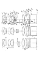
本発明の拡大内視鏡光学系の実施例1は、図1に示す通りの構成で、下記データを有する光学系である。
(物体面) d0 =D0
r1 =∞ d1 =0.36 n1 =1.88300 ν1 =40.78
r2 =1.297 d2 =0.73
r3 =∞ d3 =0.62 n2 =1.51400 ν2 =75.00
r4 =∞ d4 =1.13
r5 =-8.3111 d5 =0.88 n3 =1.48749 ν3 =70.23
r6 =-1.980 d6 =0.01
r7 =3.240 d7 =1.20 n4 =1.51633 ν4 =64.14
r8 =-2.332 d8 =0.24 n5 =2.00330 ν5 =28.27
r9 =-4.319 d9 =D1
r10 =∞(絞り) d10 =0.02
r11 =∞ d11 =0.28 n6 =1.48749 ν6 =70.23
r12=1.257 d12=0.52 n7 =1.59270 ν7 =35.31
r13=1.927 d13=D2
r14=4.593 d14=1.08 n8 =1.48749 ν8 =70.23
r15=-5.372 d15=0.02
r16=3.767 d16=1.19 n9 =1.51633 ν9 =64.14
r17=-4.774 d17=0.42 n10=1.92286 ν10=18.90
r18=52.579 d18=0.29
r19=∞ d19=0.40 n11=1.52287 ν11=59.89
r20=∞ d20=0.56
r21=∞ d21=2.75 n12=1.51633 ν12=64.14
r22=∞
通常観察状態 中間状態 近接拡大観察状態
(広角端) (望遠端)
D0 16.00 3.38 2.00
D1 0.16 1.06 1.72
D2 2.56 1.66 1.00
flw 1.758 1.959 2.024
Fno 7.0 7.2 7.3
fW/fT=0.96
|f3/f2|=0.87
|f2/f1|=2.18
fT=7.3
βT=−0.71
ω=66.5°
f3/f1=1.9
hT/hW=0.66
Enp/flw=0.73
IH/(p×1000)=0.6
ただし、r1, ・・・はレンズ各面の曲率半径、 d1,・・・は各レンズの肉厚および面間隔、n1 ,n2,・・・は各レンズのe線に対する屈折率、ν1 ,ν2,・・・は各レンズのd線に対するアッベ数である。尚、d0は物体面から光学系の第1面(r1)までの距離である。又r,d等の長さの単位はmmである。
Example 1 of the magnifying endoscope optical system according to the present invention is an optical system having the following data with the configuration shown in FIG.
(Object surface) d 0 = D0
r 1 = ∞ d 1 = 0.36 n 1 = 1.88300 ν 1 = 40.78
r 2 = 1.297 d 2 = 0.73
r 3 = ∞ d 3 = 0.62 n 2 = 1.51400 ν 2 = 75.00
r 4 = ∞ d 4 = 1.13
r 5 = -8.3111 d 5 = 0.88 n 3 = 1.48749 ν 3 = 70.23
r 6 = -1.980 d 6 = 0.01
r 7 = 3.240 d 7 = 1.20 n 4 = 1.51633 ν 4 = 64.14
r 8 = -2.332 d 8 = 0.24 n 5 = 2.00330 ν 5 = 28.27
r 9 = -4.319 d 9 = D1
r 10 = ∞ (aperture) d 10 = 0.02
r 11 = ∞ d 11 = 0.28 n 6 = 1.48749 ν 6 = 70.23
r 12 = 1.257 d 12 = 0.52 n 7 = 1.59270 ν 7 = 35.31
r 13 = 1.927 d 13 = D2
r 14 = 4.593 d 14 = 1.08 n 8 = 1.48749 ν 8 = 70.23
r 15 = -5.372 d 15 = 0.02
r 16 = 3.767 d 16 = 1.19 n 9 = 1.51633 ν 9 = 64.14
r 17 = -4.774 d 17 = 0.42 n 10 = 1.92286 ν 10 = 18.90
r 18 = 52.579 d 18 = 0.29
r 19 = ∞ d 19 = 0.40 n 11 = 1.52287 ν 11 = 59.89
r 20 = ∞ d 20 = 0.56
r 21 = ∞ d 21 = 2.75 n 12 = 1.51633 ν 12 = 64.14
r 22 = ∞
Normal observation state Intermediate state Close-up observation state
(Wide-angle end) (Telephoto end)
D0 16.00 3.38 2.00
D1 0.16 1.06 1.72
D2 2.56 1.66 1.00
flw 1.758 1.959 2.024
Fno 7.0 7.2 7.3
fW / fT = 0.96
| F3 / f2 | = 0.87
| F2 / f1 | = 2.18
fT = 7.3
βT = −0.71
ω = 66.5 °
f3 / f1 = 1.9
hT / hW = 0.66
Enp / flw = 0.73
IH / (p × 1000) = 0.6
Where r 1 ,... Are the radii of curvature of each lens surface, d 1 ,... Are the thickness and surface spacing of each lens, and n 1 , n 2 ,. , Ν 1 , ν 2 ,... Are Abbe numbers for the d-line of each lens. D 0 is the distance from the object surface to the first surface (r 1 ) of the optical system. The unit of length of r, d, etc. is mm.
この実施例1の光学系は、図1および上記データに示すように、物体側より順に、正の屈折力の第1群G1(r1〜r9)と負の屈折力の第2群G2(r11〜r13)と正の屈折力の第3群G3(r14〜r18)とにて構成されている。又明るさ絞りS(r10)は第2群G2の物体側に配置されている。 As shown in FIG. 1 and the above data, the optical system of Example 1 has a first refractive index first group G1 (r 1 to r 9 ) and a negative refractive power second group G2 in order from the object side. (R 11 to r 13 ) and a third group G3 (r 14 to r 18 ) having a positive refractive power. The aperture stop S (r 10 ) is disposed on the object side of the second group G2.
この実施例1は、第2群G2が明るさ絞りSと一体に光軸上を像側に移動して通常観察状態(広角端)から近接拡大観察状態(望遠端)への変倍と合焦を行なう。 In the first embodiment, the second group G2 moves together with the aperture stop S to the image side on the optical axis, and the magnification changes from the normal observation state (wide-angle end) to the close-up magnification observation state (telephoto end). Do chariot.
つまり、図1における上段(通常観察状態)、中段(中間状態)、下段(近接拡大観察状態)に記載するように第2群G2を光軸に沿って移動させて変倍と合焦を行なう。 That is, zooming and focusing are performed by moving the second group G2 along the optical axis as described in the upper stage (normal observation state), middle stage (intermediate state), and lower stage (close-up close-up observation state) in FIG. .
この実施例1は、図示するように、第1群G1が平凹レンズ(r1〜r2)と
平行平面板F1(r3〜r4)と像側に凸面を向けた正のメニスカスレンズ(r5〜r6)と両凸レンズ(r7〜r8)と負のメニスカスレンズ(r8〜r9)を接合した正の接合レンズ(r7〜r9)とよりなり、第2群G2が平凹レンズ(r11〜r12)と正のメニスカスレンズ(r12〜r13)を接合した接合レンズ(r11〜r13)よりなり、第3群が両凸レンズ(r14〜r15)と両凸レンズ(r16〜r17)と両凹レンズ(r17〜r18)を接合した接合レンズ(r16〜r18)とよりなる。又撮像素子の撮像面Iには撮像面を保護するためのカバーガラスC(r21〜r22)が貼り付けられている。又、第3群G3とカバーガラスCとの間には、平行平面板F2(r19〜r20)が配置されている。
In the first embodiment, as shown in the figure, the first group G1 is composed of plano-concave lenses (r 1 to r 2 ).
A plane-parallel plate F1 (r 3 to r 4 ), a positive meniscus lens (r 5 to r 6 ) having a convex surface facing the image side, a biconvex lens (r 7 to r 8 ), and a negative meniscus lens (r 8 to r 9) it becomes more and joining the positive cemented lens (r 7 ~r 9), joining the second group G2 are joined concave lens (r 11 ~r 12) and a positive meniscus lens (r 12 ~r 13) A lens (r 11 to r 13 ), and a third lens unit comprising a biconvex lens (r 14 to r 15 ), a biconvex lens (r 16 to r 17 ), and a biconcave lens (r 17 to r 18 ). r 16 to r 18 ). A cover glass C (r 21 to r 22 ) for protecting the imaging surface is attached to the imaging surface I of the imaging device. Further, a plane parallel plate F2 (r 19 to r 20 ) is disposed between the third group G3 and the cover glass C.
ここで、平行平面板F1、F2は夫々特定波長例えばYAGレーザの1060nm、半導体レーザの810nmあるいは近赤外領域の光をカットするためのフィルタである。 Here, the plane parallel plates F1 and F2 are filters for cutting light of a specific wavelength, for example, 1060 nm of a YAG laser, 810 nm of a semiconductor laser, or near-infrared region.
この実施例1は、データ中に示すように、条件(1)乃至条件(9)、条件(11)のすべての条件を満足する。また、条件(2−1)、(8−1)、(9−1)も満足する。これによって、光学系を通常観察状態(広角端)から近接拡大観察状態(望遠端)まで倍率を変化させても、Fナンバーの変動が少なく、各倍率の状態にて十分な観察深度が確保されている。 In Example 1, as shown in the data, all the conditions (1) to (9) and (11) are satisfied. Further, the conditions (2-1), (8-1), and (9-1) are also satisfied. As a result, even when the magnification of the optical system is changed from the normal observation state (wide-angle end) to the close-up magnification observation state (telephoto end), the F-number does not fluctuate and a sufficient observation depth is secured in each magnification state. ing.
又、条件(2)、(3)、(7)を満足するように各群の焦点距離を適切な値にしたことによって、画像劣化が少なくコンパクトな光学系になっている。 Further, by setting the focal length of each group to an appropriate value so as to satisfy the conditions (2), (3), and (7), a compact optical system with little image degradation is obtained.
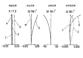
図5、図6、図7は、夫々実施例1の光学系の通常観察状態(広角端)、中間の状態、近接拡大観察状態(望遠端)における収差状況を示す。これら図より明らかなように、実施例1の光学系はFナンバーの変化が少なく、又いずれの状態にても収差が良好に補正されている。 FIGS. 5, 6, and 7 show aberration states of the optical system of Example 1 in the normal observation state (wide-angle end), the intermediate state, and the close-up magnification observation state (telephoto end), respectively. As is clear from these figures, the optical system of Example 1 has little change in the F number, and aberrations are corrected well in any state.
又、実施例1は、条件(11)を満足する高画素化された撮像素子を用いており、それにより高精細な画像が得られる。 In addition, the first embodiment uses an image sensor with a high pixel that satisfies the condition (11), and thereby a high-definition image can be obtained.
本発明の拡大内視鏡光学系の実施例2は、図2に示す通りの構成で、下記データを有する光学系である。
(物体面) d0 =D0
r1 =∞ d1 =0.36 n1 =1.88300 ν1 =40.78
r2 =1.246 d2 =0.73
r3 =∞ d3 =0.62 n2 =1.51400 ν2 =75.00
r4 =∞ d4 =0.50 n3 =1.52287 ν3 =59.89
r5 =∞ d5 =0.57
r6 =31.448 d6 =0.88 n4 =1.48749 ν4 =70.23
r7 =-2.017 d7 =0.05
r8 =3.576 d8 =1.20 n5 =1.48749 ν5 =70.23
r9 =-1.879 d9 =0.24 n6 =1.84666 ν6 =23.78
r10=-3.339 d10=D1
r11=∞(絞り) d11=0.02
r12=∞ d12=0.28 n7 =1.48749 ν7 =70.23
r13=1.678 d13=0.52 n8 =1.84666 ν8 =23.78
r14=1.703 d14=D2
r15=19.018 d15=1.29 n9 =1.48749 ν9 =70.23
r16=-2.749 d16=0.02
r17=2.793 d17=1.22 n10=1.60311 ν10=60.64
r18=-9.649 d18=0.42 n11=1.92286 ν11=18.90
r19=4.696 d19=0.87
r20=∞ d20=1.60 n12=1.51633 ν12=64.14
r21=∞
通常観察状態 中間状態 近接拡大観察状態
(広角端) (望遠端)
D0 18.00 3.38 1.80
D1 0.16 0.79 1.34
D2 2.25 1.61 1.07
flw 1.733 1.834 1.842
Fno 7.16 7.10 7.04
fW/fT=1.02
|f3/f2|=0.92
|f2/f1|=2.22
fT=7
βT=−0.71
ω=65.5°
f3/f1=2.05
hT/hW=0.79
Enp/flw=0.73
IH/(p×1000)=0.56
この実施例2の光学系は、図2および上記データに示すように、物体側より順に、正の屈折力の第1群G1(r1〜r10)と負の屈折力の第2群G2(r12〜r14)と正の屈折力の第3群G3(r15〜r19)とにて構成されている。又明るさ絞りS(r11)は第2群G2の物体側に配置されている。
Example 2 of the magnifying endoscope optical system of the present invention is an optical system having the following data with the configuration shown in FIG.
(Object surface) d 0 = D0
r 1 = ∞ d 1 = 0.36 n 1 = 1.88300 ν 1 = 40.78
r 2 = 1.246 d 2 = 0.73
r 3 = ∞ d 3 = 0.62 n 2 = 1.51400 ν 2 = 75.00
r 4 = ∞ d 4 = 0.50 n 3 = 1.52287 ν 3 = 59.89
r 5 = ∞ d 5 = 0.57
r 6 = 31.448 d 6 = 0.88 n 4 = 1.48749 ν 4 = 70.23
r 7 = −2.017 d 7 = 0.05
r 8 = 3.576 d 8 = 1.20 n 5 = 1.48749 ν 5 = 70.23
r 9 = -1.879 d 9 = 0.24 n 6 = 1.84666 ν 6 = 23.78
r 10 = -3.339 d 10 = D1
r 11 = ∞ (aperture) d 11 = 0.02
r 12 = ∞ d 12 = 0.28 n 7 = 1.48749 ν 7 = 70.23
r 13 = 1.678 d 13 = 0.52 n 8 = 1.84666 ν 8 = 23.78
r 14 = 1.703 d 14 = D2
r 15 = 19.018 d 15 = 1.29 n 9 = 1.48749 ν 9 = 70.23
r 16 = -2.749 d 16 = 0.02
r 17 = 2.793 d 17 = 1.22 n 10 = 1.60311 ν 10 = 60.64
r 18 = -9.649 d 18 = 0.42 n 11 = 1.92286 ν 11 = 18.90
r 19 = 4.696 d 19 = 0.87
r 20 = ∞ d 20 = 1.60 n 12 = 1.51633 ν 12 = 64.14
r 21 = ∞
Normal observation state Intermediate state Close-up observation state
(Wide-angle end) (Telephoto end)
D0 18.00 3.38 1.80
D1 0.16 0.79 1.34
D2 2.25 1.61 1.07
flw 1.733 1.834 1.842
Fno 7.16 7.10 7.04
fW / fT = 1.02
| F3 / f2 | = 0.92
| F2 / f1 | = 2.22
fT = 7
βT = −0.71
ω = 65.5 °
f3 / f1 = 2.05
hT / hW = 0.79
Enp / flw = 0.73
IH / (p × 1000) = 0.56
As shown in FIG. 2 and the above data, the optical system of Example 2 has, in order from the object side, a first group G1 (r 1 to r 10 ) having a positive refractive power and a second group G2 having a negative refractive power. (R 12 to r 14 ) and a third group G3 (r 15 to r 19 ) having a positive refractive power. The aperture stop S (r 11 ) is disposed on the object side of the second group G2.
この実施例2は、第2群G2が明るさ絞りSと一体に光軸に沿って像側に移動して、通常観察状態(広角端)から近接拡大観察状態(望遠端)にわたっての変倍と合焦を行なう。 In Example 2, the second lens group G2 moves to the image side along the optical axis together with the aperture stop S, and zooming from the normal observation state (wide-angle end) to the close-up magnification observation state (telephoto end). And focus.
つまり、図2における上段の通常観察状態(広角端)、中段の中間状態、下段の近接拡大観察状態(望遠端)に示すように明るさ絞りSと第2群G2を移動させて変倍と合焦を行なう。 That is, as shown in the upper normal observation state (wide-angle end), the middle intermediate state, and the lower close-up magnification observation state (telephoto end) in FIG. 2, the aperture stop S and the second group G2 are moved to change the magnification. Focus.
この実施例2は、図2に示すように、第1群G1が平凹レンズ(r1〜r2)と平行平面板F1、F2(r3〜r5)と両凸レンズ(r6〜r7)と両凸レンズ(r8〜r9)と負のメニスカスレンズ(r9〜r10)とを接合した接合レンズ(r8〜r10)とよりなり、第2群G2が平凹レンズ(r12〜r13)と正のメニスカスレンズ(r13〜r14)を接合した接合レンズ(r12〜r14)よりなり、第3群が両凸レンズ(r15〜r16)と両凸レンズ(r17〜r18)と両凹レンズ(r18〜r19)を接合した接合レンズ(r17〜r19)とよりなる。又、撮像素子の撮像面にはカバーガラス(r20〜r21)が貼り付けられている。 In Example 2, as shown in FIG. 2, the first group G1 includes plano-concave lenses (r 1 to r 2 ), parallel plane plates F1 and F2 (r 3 to r 5 ), and biconvex lenses (r 6 to r 7). ), A biconvex lens (r 8 to r 9 ) and a negative meniscus lens (r 9 to r 10 ) and a cemented lens (r 8 to r 10 ), and the second group G2 is a plano-concave lens (r 12). ˜r 13 ) and a positive meniscus lens (r 13 ˜r 14 ) and a cemented lens (r 12 ˜r 14 ). The third group consists of a biconvex lens (r 15 ˜r 16 ) and a biconvex lens (r 17). ˜r 18 ) and a cemented lens (r 17 ˜r 19 ) obtained by cementing biconcave lenses (r 18 ˜r 19 ). A cover glass (r 20 to r 21 ) is attached to the image pickup surface of the image pickup element.
尚 、平行平面板F1、F2は夫々特定波長例えばYAGレーザの1060nm、半導体レーザの810nmあるいは近赤外領域の光をカットするためのフィルタである。 The plane parallel plates F1 and F2 are filters for cutting light of a specific wavelength, for example, 1060 nm of a YAG laser, 810 nm of a semiconductor laser, or near infrared region.
この実施例2も、データに示すように条件(1)乃至条件(9)、条件(11)のすべての条件を満足する光学系であり、それにより、通常観察状態(広角端)から近接拡大観察状態(望遠端)までのすべての変倍状態において、Fナンバーの変動が少なく、各倍率の状態にて十分な観察深度が得られる。また、条件(2−1)、(8−1)、(9−1)も満足する。 This Example 2 is also an optical system that satisfies all of the conditions (1) to (9) and (11) as shown in the data, and thereby close-up from the normal observation state (wide-angle end). In all zooming states up to the observation state (telephoto end), there is little fluctuation of the F number, and a sufficient observation depth can be obtained in each magnification state. Further, the conditions (2-1), (8-1), and (9-1) are also satisfied.
又、この実施例2も、第1群、第2群、第3群の夫々の焦点距離が条件(2)、(3)、(7)を満足するように適切な値に設定してあり、それにより各状態において画質の劣化がなく、コンパクトな撮像光学系になっている。 In the second embodiment, the focal lengths of the first group, the second group, and the third group are set to appropriate values so as to satisfy the conditions (2), (3), and (7). Thereby, there is no deterioration in image quality in each state, and the imaging optical system is compact.
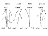
図8、図9、図10の収差図に示すように、実施例2の通常観察状態(広角端)、中間状態、近接拡大観察状態(望遠端)における諸収差はいずれも良好に補正されている。 As shown in the aberration diagrams of FIGS. 8, 9, and 10, various aberrations in the normal observation state (wide-angle end), the intermediate state, and the close-up magnification observation state (telephoto end) of Example 2 are all well corrected. Yes.
又、この実施例2も、条件(11)を満足する高画素化された撮像素子を用いることにより高精細な画像を得ることができる。 Also in the second embodiment, a high-definition image can be obtained by using an image pickup device with a high pixel that satisfies the condition (11).
本発明の光学系の実施例3は、図3に示す通りの構成で、下記データを有する。
(物体面) d0 =D0
r1 =∞ d1 =0.45 n1 =1.88300 ν1 =40.78
r2 =1.886 d2 =1.00
r3 =∞ d3 =0.57 n2 =1.52287 ν2 =59.89
r4 =∞ d4 =0.47
r5 =-6.999 d5 =2.75 n3 =1.69895 ν3 =30.13
r6 =-3.383 d6 =D1
r7 =3.920 d7 =0.61 n4 =1.88300 ν4 =40.76
r8 =9.496 d8 =D2
r9 =∞(絞り) d9 =0.09
r10=33.957 d10=0.27 n5 =1.84666 ν5 =23.78
r11=1.805 d11=2.03 n6 =1.51633 ν6 =64.14
r12=-6.057 d12=0.08
r13=5.501 d13=1.09 n7 =1.88300 ν7 =40.76
r14=3.662 d14=0.77 n8 =1.80100 ν8 =34.97
r15=-15.338 d15=1.82
r16=∞ d16=2.00 n9 =1.51400 ν9 =75.00
r17=∞
通常観察状態 中間状態 近接拡大観察状態
(広角端) (望遠端)
D0 23.50 10.50 3.00
D1 3.26 2.92 1.53
D2 0.39 0.72 2.12
flw 1.480 1.537 1.825
Fno 9.10 9.10 9.10
fW/fT=1
|f3/f2|=0.81
|f2/f1|=0.36
fT=9.1
βT=−0.4
ω=60.7°
f3/f1=−0.29
hT/hW=1.00
Enp/flw=1.33
IH/(p×1000)=0.43
この実施例3は、図3に示すように、物体側より順に、負の屈折力の第1群G1(r1〜r6)と正の屈折力の第2群G2(r7〜r8)と正の屈折力の第3群G3(r10〜r15)とよりなる。
Example 3 of the optical system of the present invention has the following data with the configuration shown in FIG.
(Object surface) d 0 = D0
r 1 = ∞ d 1 = 0.45 n 1 = 1.88300 ν 1 = 40.78
r 2 = 1.886 d 2 = 1.00
r 3 = ∞ d 3 = 0.57 n 2 = 1.52287 ν 2 = 59.89
r 4 = ∞ d 4 = 0.47
r 5 = -6.999 d 5 = 2.75 n 3 = 1.69895 ν 3 = 30.13
r 6 = -3.383 d 6 = D1
r 7 = 3.920 d 7 = 0.61 n 4 = 1.88300 ν 4 = 40.76
r 8 = 9.496 d 8 = D2
r 9 = ∞ (aperture) d 9 = 0.09
r 10 = 33.957 d 10 = 0.27 n 5 = 1.84666 ν 5 = 23.78
r 11 = 1.805 d 11 = 2.03 n 6 = 1.51633 ν 6 = 64.14
r 12 = −6.057 d 12 = 0.08
r 13 = 5.501 d 13 = 1.09 n 7 = 1.88300 ν 7 = 40.76
r 14 = 3.662 d 14 = 0.77 n 8 = 1.80100 ν 8 = 34.97
r 15 = -15.338 d 15 = 1.82
r 16 = ∞ d 16 = 2.00 n 9 = 1.51400 ν 9 = 75.00
r 17 = ∞
Normal observation state Intermediate state Close-up observation state
(Wide-angle end) (Telephoto end)
D0 23.50 10.50 3.00
D1 3.26 2.92 1.53
D2 0.39 0.72 2.12
flw 1.480 1.537 1.825
Fno 9.10 9.10 9.10
fW / fT = 1
| F3 / f2 | = 0.81
| F2 / f1 | = 0.36
fT = 9.1
βT = −0.4
ω = 60.7 °
f3 / f1 = −0.29
hT / hW = 1.00
Enp / flw = 1.33
IH / (p × 1000) = 0.43
In the third embodiment, as shown in FIG. 3, in order from the object side, the first group G1 (r 1 to r 6 ) having a negative refractive power and the second group G2 (r 7 to r 8 ) having a positive refractive power are arranged. ) and a more positive refractive power third group G3 (r 10 ~r 15).
この実施例3は、正の屈折力の第2群G2を光軸に沿って像側から物体側へ移動させることにより、通常観察状態(広角端)から近接拡大観察状態(望遠端)までの変倍と合焦を行なうもので、明るさ絞りSは第3群G3の物体側に配置されており、変倍中移動せずに固定されている。 In Example 3, the second group G2 having a positive refractive power is moved from the image side to the object side along the optical axis, so that the normal observation state (wide-angle end) to the close-up magnification observation state (telephoto end) For performing zooming and focusing, the aperture stop S is disposed on the object side of the third lens group G3, and is fixed without moving during zooming.
つまり、この実施例3は、負、正、正の三つのレンズ群よりなり正の第2群G2を移動させて変倍を行なうことと、明るさ絞りが第3群の物体側に変倍中移動せずに固定配置されている点で、実施例1、2と異なる構成である。 That is, in the third embodiment, zooming is performed by moving the positive second group G2 including three lens groups of negative, positive, and positive, and the aperture stop is zoomed toward the object side of the third group. This is a configuration different from the first and second embodiments in that it is fixedly arranged without moving in the middle.
実施例3は、負の第1群G1が、平凹レンズ(r1〜r2)と平行平面板F1(r3〜r4)と正のメニスカスレンズ(r5〜r6)とよりなり、第2群G2が正のメニスカスレンズ(r7〜r8)1枚よりなり、第3群G3が負のメニスカスレンズ(r10〜r11)と両凸レンズ(r11〜r12)を接合した接合レンズ(r10〜r12)と負のメニスカスレンズ(r13〜r14)と両凸レンズ(r14〜r15)を接合した接合レンズ(r13〜r15)とよりなり、撮像素子の撮像面IにはカバーガラスCが貼り付けられている。 In Example 3, the negative first group G1 includes a plano-concave lens (r 1 to r 2 ), a plane parallel plate F1 (r 3 to r 4 ), and a positive meniscus lens (r 5 to r 6 ). the second group G2 consists of a positive meniscus lens (r 7 ~r 8) 1 sheet was the third group G3 has joined a negative meniscus lens (r 10 ~r 11) and a biconvex lens (r 11 ~r 12) cemented lens (r 10 ~r 12) and more becomes a negative meniscus lens (r 13 ~r 14) and a biconvex lens (r 14 ~r 15) the bonded cemented lens (r 13 ~r 15), the imaging device A cover glass C is attached to the imaging surface I.
明るさ絞りS(r9)は第3群G3の物体側に固定配置されている。又平行平面板F1は特定波長例えばYAGレーザの1060nm、半導体レーザの810nmあるいは近赤外領域の光をカットするためのフィルタである。 The aperture stop S (r 9 ) is fixedly disposed on the object side of the third group G3. The plane parallel plate F1 is a filter for cutting light of a specific wavelength, for example, 1060 nm of a YAG laser, 810 nm of a semiconductor laser, or near infrared region.
この実施例3は、条件(1)、(2)、(4)、(6)、(8)、(9)、(11)、(2−1)を満足する。 In Example 3, the conditions (1), (2), (4), (6), (8), (9), (11), and (2-1) are satisfied.
この実施例3は、前述のように負、正、正の構成で、明るさ絞りSを第2群G2と第3群G3の間でその像面側に近づけて固定配置したことによって、明るさ絞りSを変倍時固定配置したままでもFナンバーの変動がなく、通常観察状態(広角端)から近接拡大観察状態(望遠端)までの各状態で十分な観察深度が得られる。 In this third embodiment, as described above, the aperture stop S is fixed between the second group G2 and the third group G3 so as to be close to the image plane side in a negative, positive, and positive configuration. Even when the aperture stop S is fixedly arranged at the time of zooming, the F number does not fluctuate, and a sufficient observation depth can be obtained in each state from the normal observation state (wide-angle end) to the close-up magnification observation state (telephoto end).
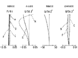
この実施例3の収差状況は、図11、12、13に示す通りである。これら図のうち図11は通常観察状態(広角端)、図12は中間状態、図13は近接拡大観察状態(望遠端)の収差図で、Fナンバーの変化は少なく、いずれの状態も諸収差が良好に補正されており、収差の変動も少ない。 The aberration status of Example 3 is as shown in FIGS. Among these drawings, FIG. 11 is an aberration diagram in a normal observation state (wide-angle end), FIG. 12 is an intermediate state, and FIG. 13 is an aberration diagram in a close-up magnification observation state (telephoto end). Is corrected well, and there is little variation in aberrations.
この実施例3も、条件(11)を満足する高画素化された撮像素子を用いることにより、各状態において高精細な画像を得ることができる。 Also in the third embodiment, a high-definition image can be obtained in each state by using an image pickup device with a high pixel that satisfies the condition (11).
本発明の光学系の実施例4は、図4に示す通りの構成で、下記データを有する。
(物体面) d0 =D0
r1 =∞ d1 =0.36 n1 =1.88300 ν1 =40.78
r2 =1.318 d2 =0.73
r3 =∞ d3 =0.62 n2 =1.51400 ν2 =75.00
r4 =∞ d4 =0.47
r5 =7.097 d5 =1.69 n3 =1.48749 ν3 =70.23
r6 =-1.911 d6 =0.24 n4 =1.84666 ν4 =23.78
r7 =-2.140 d7 =0.02
r8 =4.116 d8 =0.82 n5 =1.64000 ν5 =60.08
r9 =-2.181 d9 =0.12 n6 =2.00330 ν6 =28.27
r10=-5.343 d10=D1
r11=∞(絞り) d11=0.02
r12=-5.181 d12=0.19 n7 =1.60300 ν7 =65.44
r13=1.143 d13=0.24 n8 =1.68893 ν8 =31.07
r14=2.182 d14=D2
r15=6.990 d15=1.00 n9 =1.48749 ν9 =70.23
r16=-3.748 d16=0.12
r17=3.540 d17=1.16 n10=1.49700 ν10=81.54
r18=-5.952 d18=0.22
r19=-4.732 d19=0.42 n11=1.92286 ν11=18.90
r20=-90.467 d20=1.55
r21=∞ d21=0.40 n12=1.52287 ν12=59.89
r22=∞ d22=1.35
r23=∞ d23=1.20 n13=1.51633 ν13=64.14
r24=∞
通常観察状態 中間状態 近接拡大観察状態
(広角端) (望遠端)
D0 20.00 2.00 0.88
D1 0.15 1.47 2.53
D2 2.57 1.26 0.20
flw 1.787 2.336 2.157
Fno 5.87 6.87 7.66
fW/fT=0.77
|f3/f2|=1.34
|f2/f1|=1.59
fT=7.7
βT=−1.73
ω=66.5°
f3/f1=2.13
hT/hW=0.48
Enp/flw=0.72
IH/(p×1000)=0.49
この実施例4は、図4に示すように物体側より順に、正の屈折力の第1群G1と、負の屈折力の第2群G2と、正の屈折力の第3群G3とよりなる。そして、第2群G2を光軸に沿って物体側より像側へ移動させることにより、通常観察状態(広角端)から近接拡大観察状態(望遠端)への変倍と合焦とを行なっている。又、明るさ絞りSは第2群G2の物体側に配置され、変倍時第2群G2と一体に移動する。
Example 4 of the optical system of the present invention has the following data with the configuration shown in FIG.
(Object surface) d 0 = D0
r 1 = ∞ d 1 = 0.36 n 1 = 1.88300 ν 1 = 40.78
r 2 = 1.318 d 2 = 0.73
r 3 = ∞ d 3 = 0.62 n 2 = 1.51400 ν 2 = 75.00
r 4 = ∞ d 4 = 0.47
r 5 = 7.097 d 5 = 1.69 n 3 = 1.48749 ν 3 = 70.23
r 6 = -1.911 d 6 = 0.24 n 4 = 1.84666 ν 4 = 23.78
r 7 = -2.140 d 7 = 0.02
r 8 = 4.116 d 8 = 0.82 n 5 = 1.64000 ν 5 = 60.08
r 9 = -2.181 d 9 = 0.12 n 6 = 2.00330 ν 6 = 28.27
r 10 = -5.343 d 10 = D1
r 11 = ∞ (aperture) d 11 = 0.02
r 12 = -5.181 d 12 = 0.19 n 7 = 1.60300 ν 7 = 65.44
r 13 = 1.143 d 13 = 0.24 n 8 = 1.68893 ν 8 = 31.07
r 14 = 2.182 d 14 = D2
r 15 = 6.990 d 15 = 1.00 n 9 = 1.48749 ν 9 = 70.23
r 16 = -3.748 d 16 = 0.12
r 17 = 3.540 d 17 = 1.16 n 10 = 1.49700 ν 10 = 81.54
r 18 = -5.952 d 18 = 0.22
r 19 = -4.732 d 19 = 0.42 n 11 = 1.92286 ν 11 = 18.90
r 20 = -90.467 d 20 = 1.55
r 21 = ∞ d 21 = 0.40 n 12 = 1.52287 ν 12 = 59.89
r 22 = ∞ d 22 = 1.35
r 23 = ∞ d 23 = 1.20 n 13 = 1.51633 ν 13 = 64.14
r 24 = ∞
Normal observation state Intermediate state Close-up observation state
(Wide-angle end) (Telephoto end)
D0 20.00 2.00 0.88
D1 0.15 1.47 2.53
D2 2.57 1.26 0.20
flw 1.787 2.336 2.157
Fno 5.87 6.87 7.66
fW / fT = 0.77
| F3 / f2 | = 1.34
| F2 / f1 | = 1.59
fT = 7.7
βT = −1.73
ω = 66.5 °
f3 / f1 = 2.13
hT / hW = 0.48
Enp / flw = 0.72
IH / (p × 1000) = 0.49
In the fourth embodiment, as shown in FIG. 4, in order from the object side, a first group G1 having a positive refractive power, a second group G2 having a negative refractive power, and a third group G3 having a positive refractive power. Become. Then, by moving the second group G2 from the object side to the image side along the optical axis, zooming and focusing from the normal observation state (wide-angle end) to the close-up magnification observation state (telephoto end) are performed. Yes. The aperture stop S is disposed on the object side of the second group G2, and moves together with the second group G2 during zooming.
つまり、図4における上段(通常観察状態)、中段(中間状態)、下段(近接拡大観察状態)に示すように第2群G2が明るさ絞りSと一体に移動する。 That is, the second group G2 moves integrally with the aperture stop S as shown in the upper stage (normal observation state), middle stage (intermediate state), and lower stage (close-up close-up observation state) in FIG.
この実施例4は、図4に示すように、第1群G1が平凹レンズ(r1〜r2)と平行平面板F1(r3〜r4)と両凸レンズ(r5〜r6)とメニスカスレンズ(r6〜r7)を接合した接合レンズ(r5〜r7)と両凸レンズ(r8〜r9)と負のメニスカスレンズ(r9〜r10)を接合した接合レンズ(r8〜r10)とよりなり、第2群G2は両凹レンズ(r12〜r13)と正のメニスカスレンズ(r13〜r14)を接合した接合レンズ(r12〜r14)よりなり、第3群G3は両凸レンズ2枚(r15〜r16)および(r17〜r18)と負のメニスカスレンズ(r19〜r20)よりなる。 In Example 4, as shown in FIG. 4, the first group G1 includes plano-concave lenses (r 1 to r 2 ), parallel plane plates F1 (r 3 to r 4 ), and biconvex lenses (r 5 to r 6 ). meniscus lens (r 6 ~r 7) the bonded cemented lens (r 5 ~r 7) and a biconvex lens (r 8 ~r 9) and a negative meniscus lens (r 9 ~r 10) the bonded cemented lens (r 8 ~r 10) and becomes more, the second group G2 consists of a biconcave lens (r 12 ~r 13) and a positive meniscus lens (r 13 ~r 14) the bonded cemented lens (r 12 ~r 14), The third group G3 includes two biconvex lenses (r 15 to r 16 ) and (r 17 to r 18 ) and a negative meniscus lens (r 19 to r 20 ).
又、撮像素子の撮像面IにはカバーガラスC(r23〜r24)が貼り付けられている。第3群G3とカバーガラスCとの間には平行平面板F2(r21〜r22)が配置されている。 A cover glass C (r 23 to r 24 ) is attached to the image pickup surface I of the image pickup element. A plane parallel plate F2 (r 21 to r 22 ) is disposed between the third group G3 and the cover glass C.
ここで、平行平面板F1、F2は夫々特定波長例えばYAGレーザの1060nm、半導体レーザの810nmあるいは近赤外領域の光をカットするためのフィルタである。 Here, the plane parallel plates F1 and F2 are filters for cutting light of a specific wavelength, for example, 1060 nm of a YAG laser, 810 nm of a semiconductor laser, or near-infrared region.
明るさ絞りS(r11)は第2群G2の物体側に配置され、変倍の際に第2群G2と一体に光軸上を移動するように構成されている。 The aperture stop S (r 11 ) is disposed on the object side of the second group G2, and is configured to move on the optical axis integrally with the second group G2 during zooming.
この実施例4の光学系は、条件(2)乃至条件(7)、条件(9)、条件(11)を満足する。 The optical system of Example 4 satisfies the conditions (2) to (7), the condition (9), and the condition (11).
この実施例4は条件(5−1)を満足するように構成されている。そのために、この実施例は、近接拡大観察状態(望遠端)において生体組織を細胞レベルで観察することが可能であり、又通常観察状態(広角端)では、高視野が確保され、病変部を発見するために生体内をスクリーニングしたり、病変部に処置を施す等の作業を行なうことができる。 The fourth embodiment is configured to satisfy the condition (5-1). Therefore, in this embodiment, it is possible to observe the living tissue at the cellular level in the close-up magnification observation state (telephoto end), and in the normal observation state (wide-angle end), a high field of view is ensured, and the lesioned part is observed. In order to find out, it is possible to perform operations such as screening the inside of a living body or performing treatment on a lesioned part.
この実施例4のように、近接拡大観察状態(望遠端)での観察倍率が条件(5−1)を満足するようにした場合、条件(1)を満足するように構成することが困難になる。そのため、実施例4は条件(1)を満足しない。 When the observation magnification in the close-up magnification observation state (telephoto end) satisfies the condition (5-1) as in the fourth embodiment, it is difficult to configure to satisfy the condition (1). Become. Therefore, Example 4 does not satisfy the condition (1).
しかし、物体側から順に、正、負、正のレンズ群にて構成し、通常観察状態(広角端)から近接拡大観察状態(望遠端)まで変倍状態を変化させる時に第2群G2と共に明るさ絞りSを一体に移動させるようにし、各群のパワー配分を適切なものとすることにより、高画素化された撮像素子と組み合わせた場合でも、Fナンバーがさほど大きく変動しないため、各変倍状態において支障のない観察深度を確保することができる。 However, in order from the object side, a positive lens unit, a negative lens unit, and a positive lens unit are used. When the zooming state is changed from the normal observation state (wide-angle end) to the close-up magnification observation state (telephoto end), the second group G2 is bright. Since the aperture stop S is moved integrally and the power distribution of each group is appropriate, even when combined with an image pickup device with a high pixel count, the F number does not vary so much. An observation depth that does not hinder the state can be ensured.
具体的には、近接拡大観察状態(望遠端)でのFナンバーを回折限界近傍まで大にし、観察深度の極近点側で所望の解像力を確保すると共に、通常観察状態(広角端)ではFナンバーがより小さくなってしまうにもかかわらず、観察深度の遠点側で所望の解像力が得られる程度に明るさ絞りの開口径を設定してある。 又、この実施例4は、Fナンバーが小さいために明るい光学系を実現し得るという大きなメリットを有する。 Specifically, the F number in the close-up magnification observation state (telephoto end) is increased to the vicinity of the diffraction limit, and a desired resolving power is secured on the very near point side of the observation depth, while F in the normal observation state (wide-angle end). The aperture diameter of the aperture stop is set to such an extent that a desired resolving power can be obtained on the far point side of the observation depth in spite of the fact that the number becomes smaller. Further, the fourth embodiment has a great merit that a bright optical system can be realized because the F-number is small.
この実施例4の光学系も、第1群G1、第2群G2、第3群G3の各レンズ群の焦点距離が条件(2)、(3)、(7)を満足し、適切な値に設定してあるため、画像の劣化がなく、しかもコンパクトな構成の光学系である。 Also in the optical system of Example 4, the focal lengths of the lens units of the first group G1, the second group G2, and the third group G3 satisfy the conditions (2), (3), and (7), and are appropriate values. Therefore, the optical system has a compact configuration with no image deterioration.
図14、図15、図16は、夫々この実施例4の通常観察状態(広角端)、中間状態、近接拡大観察状態(望遠端)における収差図である。 FIGS. 14, 15, and 16 are aberration diagrams of Example 4 in the normal observation state (wide-angle end), the intermediate state, and the close-up magnification observation state (telephoto end), respectively.
これら図から明らかなように、実施例4の光学系は、通常観察状態(広角端)から近接拡大観察状態(望遠端)までの各状態においてFナンバーの変化が少なく、又諸収差が良好に補正され収差の変動の少ない光学系である。 As is clear from these figures, the optical system of Example 4 has little change in F-number in each state from the normal observation state (wide-angle end) to the close-up magnification observation state (telephoto end), and various aberrations are good. It is an optical system that is corrected and has little fluctuation in aberration.
又、この実施例4の光学系も、条件(11)を満足する高画素化された撮像素子と組み合わせて使用することにより、各変倍状態おいて高精細な画像を得ることが可能である。 The optical system of Example 4 can also obtain a high-definition image in each zooming state by using it in combination with an image sensor with a high pixel that satisfies the condition (11). .
特許請求の範囲に記載する光学系のほか次の各項に記載する光学系も、本発明の目的を達成し得る。 In addition to the optical system described in the claims, the optical system described in each of the following items can also achieve the object of the present invention.
(1) 請求項1に記載された光学系で、前記対物レンズが、物体側から順に、正の第1群と負の第2群と正の第3群とにて構成され、負の第2群と明るさ絞りが一体に光軸上を移動することによって合焦と変倍とを行なうことを特徴とする拡大内視鏡光学系。 (1) In the optical system according to claim 1, the objective lens includes, in order from the object side, a positive first group, a negative second group, and a positive third group. An enlarging endoscope optical system characterized in that focusing and zooming are performed by moving the second group and the aperture stop together on the optical axis.
(2) 特許請求の範囲の請求項1又は4あるいは前記の(1)に記載された光学系で、下記条件(4)を満足することを特徴とする拡大内視鏡光学系。
(2) An enlarging endoscope optical system that satisfies the following condition (4) in the optical system described in
(4) F(T)<9.5
(3) 特許請求の範囲の請求項2又は3に記載された光学系で、下記条件(5−1)を満足することを特徴とする拡大内視鏡光学系。
(4) F (T) <9.5
(3) An magnifying endoscope optical system that satisfies the following condition (5-1) in the optical system according to claim 2 or 3.
(5−1) β(T)<−1.5
(4) 前記(3)の項に記載された光学系で、下記条件(6)を満足することを特徴とする拡大内視鏡光学系。
(5-1) β (T) <− 1.5
(4) An magnifying endoscope optical system that satisfies the following condition (6) in the optical system described in the item (3).
(6) ω>60°
(5) 複数のレンズ群より構成され、一つのレンズ群のみが光軸上を移動することにより合焦と変倍を行なう光学系で、下記条件(5−1)、(6)を満足することを特徴とする拡大内視鏡光学系。
(6) ω> 60 °
(5) An optical system composed of a plurality of lens groups, in which only one lens group moves on the optical axis for focusing and zooming, and satisfies the following conditions (5-1) and (6): Magnifying endoscope optical system characterized by that.
(5−1) β(T)<−1.5
(6) ω>60°
(6) 前記の(5)の項に記載された光学系で、物体側から順に、正の第1群と負の第2群と正の第3群とにて構成され、負の第2群が光軸上を移動することにより合焦と変倍とを行なうことを特徴とする拡大内視鏡光学系。
(5-1) β (T) <− 1.5
(6) ω> 60 °
(6) In the optical system described in the item (5), the optical system includes, in order from the object side, a positive first group, a negative second group, and a positive third group. An enlarging endoscope optical system characterized in that focusing and zooming are performed by moving a group on an optical axis.
(7) 特許請求の範囲の請求項1、2、3又は4あるいは前記の(1)、(2)、(3)、(4)、(5)又は(6)に記載された光学系で、合焦および変倍中、光学系中に設けられた明るさ絞りの径が変化しないことを特徴とする拡大内視鏡光学系。
(7) In the optical system described in
(8) レンズ系を構成するレンズ群中の一部のレンズ群が光軸上を移動することによって、少なくとも通常観察状態(広角端)と近接拡大観察状態(望遠端)とを取り得る対物レンズと、対物レンズの結像面近傍に撮像面が位置するように撮像素子を配置した光学系で、下記条件(1)、(11)を満足することを特徴とする拡大内視鏡光学系。 (8) An objective lens capable of taking at least a normal observation state (wide-angle end) and a close-up magnification observation state (telephoto end) by moving a part of the lens groups constituting the lens system on the optical axis. And an enlarging endoscope optical system that satisfies the following conditions (1) and (11), wherein the imaging element is disposed so that the imaging surface is positioned in the vicinity of the imaging surface of the objective lens.
(1) F(W)/F(T)>0.93
(11) 0.4<IH/(p×1000)<0.7
(9) 物体側から順に、正の第1群と負の第2群と正の第3群とより構成される対物レンズと、前記対物レンズの結像面近傍に撮像面が位置するように配置された撮像素子とよりなる光学系で、前記明るさ絞りと一体に負の第2群が光軸上を移動して合焦と変倍を行なう光学系で、下記条件(2)、(11)を満足することを特徴とする拡大内視鏡光学系。
(1) F (W) / F (T)> 0.93
(11) 0.4 <IH / (p × 1000) <0.7
(9) In order from the object side, an objective lens composed of a positive first group, a negative second group, and a positive third group, and an imaging surface positioned in the vicinity of the imaging surface of the objective lens An optical system composed of an image pickup device arranged, and an optical system in which a negative second group moves on the optical axis integrally with the aperture stop and performs focusing and zooming. The following conditions (2), ( The magnifying endoscope optical system characterized by satisfying 11).
(2) 0.4<|f3/f2|<1.38
(11) 0.4<IH/(p×1000)<0.7
(10) 前記(9)の項に記載された光学系で、下記条件(3)を満足することを特徴とする拡大内視鏡光学系。
(2) 0.4 <| f3 / f2 | <1.38
(11) 0.4 <IH / (p × 1000) <0.7
(10) An magnifying endoscope optical system that satisfies the following condition (3) in the optical system described in the item (9).
(3) 1.5<|f2/f1|<3.5
(11) 前記(9)又は(10)の項に記載された光学系で、下記条件(1)を満足することを特徴とする拡大内視鏡光学系。
(3) 1.5 <| f2 / f1 | <3.5
(11) An magnifying endoscope optical system that satisfies the following condition (1) in the optical system described in the item (9) or (10).
(1) F(W)/F(T)>0.93
(12) 前記(8)の項に記載された光学系で、前記対物レンズが、物体側から順に、正の第1群と負の第2群と正の第3群とより構成され、負の第2群と前記明るさ絞りとが一体に光軸上を移動することによって合焦と変倍を行なうことを特徴とする拡大内視鏡光学系。
(1) F (W) / F (T)> 0.93
(12) In the optical system described in (8), the objective lens includes, in order from the object side, a positive first group, a negative second group, and a positive third group. A magnifying endoscope optical system characterized in that focusing and zooming are performed by moving the second lens group and the aperture stop together on the optical axis.
(13) 前記(8)、(11)又は(12)の項に記載された光学系で、下記条件(4)を満足することを特徴とする拡大内視鏡光学系。 (13) An magnifying endoscope optical system that satisfies the following condition (4) in the optical system described in the item (8), (11), or (12).
(4) F(T)<9.5
(14) 前記(9)又は(10)の項に記載された光学系で、下記条件(5−1)を満足することを特徴とする拡大内視鏡光学系。
(4) F (T) <9.5
(14) An enlarging endoscope optical system that satisfies the following condition (5-1) in the optical system described in the item (9) or (10).
(5−1) β(T)<−1.5
(15) 前記(14)の項に記載された光学系で、下記条件(6)を満足することを特徴とする拡大内視鏡光学系。
(5-1) β (T) <− 1.5
(15) An magnifying endoscope optical system that satisfies the following condition (6) in the optical system described in the item (14).
(6) ω>60°
(16) 複数のレンズ群よりなり、レンズ群中の一つのレンズ群のみを移動させることにより合焦および変倍を行なう対物レンズと、対物レンズの結像面近傍に撮像面が位置する撮像素子とを備えた光学系で、下記条件(5−1)、(6)、(11)を満足することを特徴とする拡大内視鏡光学系。
(6) ω> 60 °
(16) An objective lens that includes a plurality of lens groups and performs focusing and zooming by moving only one lens group in the lens group, and an imaging element in which an imaging surface is positioned in the vicinity of the imaging surface of the objective lens An magnifying endoscope optical system characterized by satisfying the following conditions (5-1), (6), and (11).
(5−1) β(T)<−1.5
(6) ω>60°
(11) 0.4<IH/(p×1000)<0.7
(17) 前記(16)の項に記載された光学系で、前記対物レンズが、物体側から順に、正の第1群と負の第2群と正の第3群とより構成され、負の第2群が光軸上を移動して合焦と変倍を行なうことを特徴とする拡大内視鏡光学系。
(5-1) β (T) <− 1.5
(6) ω> 60 °
(11) 0.4 <IH / (p × 1000) <0.7
(17) In the optical system described in (16), the objective lens includes, in order from the object side, a positive first group, a negative second group, and a positive third group. A magnifying endoscope optical system, wherein the second group of the lens unit moves on the optical axis to perform focusing and zooming.
Claims (4)
(1) F(W)/F(T)>0.93
ただし、F(W)、F(T)は夫々通常観察状態(広角端)および近接拡大観察状態(望遠端)での光学系のFナンバーである。 An magnifying endoscope optical system that satisfies the following condition (1) with an objective lens that can be in at least a normal observation state and a close-up magnification observation state by moving some lens groups.
(1) F (W) / F (T)> 0.93
However, F (W) and F (T) are the F numbers of the optical system in the normal observation state (wide-angle end) and the close-up magnification observation state (telephoto end), respectively.
(2) 0.4<|f3/f2|<1.38
ただし、f2、f3は夫々第2群、第3群の焦点距離である。 In order from the object side, the objective lens is composed of a positive first group, a negative second group, and a positive third group, and the negative second group moves on the optical axis integrally with the aperture stop. A magnifying endoscope optical system that performs focusing and variable magnification by satisfying the following condition (2).
(2) 0.4 <| f3 / f2 | <1.38
However, f2 and f3 are the focal lengths of the second group and the third group, respectively.
(3) 1.5<|f2/f1|<3.5
ただし、f1、f2は夫々第1群、第2群の焦点距離である。 The magnifying endoscope optical system according to claim 2, which satisfies the following condition (3).
(3) 1.5 <| f2 / f1 | <3.5
Here, f1 and f2 are the focal lengths of the first group and the second group, respectively.
(1) F(W)/F(T)>0.93
ただし、F(W)、F(T)は夫々通常観察状態(広角端)および近接拡大観察状態(望遠端)での光学系のFナンバーである。
The magnifying endoscope optical system according to claim 2 or 3, which satisfies the following condition (1).
(1) F (W) / F (T)> 0.93
However, F (W) and F (T) are the F numbers of the optical system in the normal observation state (wide-angle end) and the close-up magnification observation state (telephoto end), respectively.
Priority Applications (2)
| Application Number | Priority Date | Filing Date | Title |
|---|---|---|---|
| JP2006054498A JP4659645B2 (en) | 2006-03-01 | 2006-03-01 | Magnifying endoscope optical system |
| US11/710,662 US7499226B2 (en) | 2006-03-01 | 2007-02-23 | Magnifying optical system for endoscope |
Applications Claiming Priority (1)
| Application Number | Priority Date | Filing Date | Title |
|---|---|---|---|
| JP2006054498A JP4659645B2 (en) | 2006-03-01 | 2006-03-01 | Magnifying endoscope optical system |
Publications (2)
| Publication Number | Publication Date |
|---|---|
| JP2007233036A true JP2007233036A (en) | 2007-09-13 |
| JP4659645B2 JP4659645B2 (en) | 2011-03-30 |
Family
ID=38471222
Family Applications (1)
| Application Number | Title | Priority Date | Filing Date |
|---|---|---|---|
| JP2006054498A Active JP4659645B2 (en) | 2006-03-01 | 2006-03-01 | Magnifying endoscope optical system |
Country Status (2)
| Country | Link |
|---|---|
| US (1) | US7499226B2 (en) |
| JP (1) | JP4659645B2 (en) |
Cited By (20)
| Publication number | Priority date | Publication date | Assignee | Title |
|---|---|---|---|---|
| JP2009251432A (en) * | 2008-04-09 | 2009-10-29 | Olympus Medical Systems Corp | Objective optical system for endoscope |
| EP2131225A2 (en) | 2008-06-06 | 2009-12-09 | Olympus Medical Systems Corporation | Objective optical system |
| JP2011193983A (en) * | 2010-03-18 | 2011-10-06 | Olympus Corp | Endoscope system, imaging apparatus, and control method |
| JP2012032576A (en) * | 2010-07-30 | 2012-02-16 | Hoya Corp | Variable power optical system for endoscope and endoscope |
| US8284494B2 (en) | 2011-02-22 | 2012-10-09 | Olympus Corporation | Optical system |
| US8310769B2 (en) | 2009-09-30 | 2012-11-13 | Olympus Corporation | Optical system |
| US8331039B2 (en) | 2009-09-30 | 2012-12-11 | Olympus Corporation | Optical system |
| WO2013069263A1 (en) * | 2011-11-08 | 2013-05-16 | 富士フイルム株式会社 | Objective lens for endoscope, and endoscope |
| WO2014045800A1 (en) * | 2012-09-18 | 2014-03-27 | オリンパスメディカルシステムズ株式会社 | Endoscope objective lens |
| WO2014088104A1 (en) * | 2012-12-07 | 2014-06-12 | オリンパス株式会社 | Objective lens and observation device equipped with same |
| JP5580956B1 (en) * | 2013-03-26 | 2014-08-27 | オリンパスメディカルシステムズ株式会社 | Endoscope optical system |
| WO2014132494A1 (en) * | 2013-02-28 | 2014-09-04 | オリンパスメディカルシステムズ株式会社 | Objective optical system |
| WO2014155821A1 (en) | 2013-03-26 | 2014-10-02 | オリンパスメディカルシステムズ株式会社 | Optical system for endoscope |
| WO2015025802A1 (en) | 2013-08-22 | 2015-02-26 | オリンパスメディカルシステムズ株式会社 | Enlarging endoscope optical system |
| US9019621B2 (en) | 2011-11-11 | 2015-04-28 | Olympus Corporation | Objective optical system and observation apparatus provided with the same |
| WO2015194311A1 (en) * | 2014-06-20 | 2015-12-23 | オリンパス株式会社 | Objective optical system for endoscope |
| US10095013B2 (en) | 2014-11-26 | 2018-10-09 | Olympus Corporation | Objective optical system |
| JP2021100574A (en) * | 2013-03-14 | 2021-07-08 | ルミセル, インコーポレーテッドLumicell, Inc. | Medical imaging device and use method |
| US11771324B1 (en) | 2017-08-23 | 2023-10-03 | Lumicell, Inc. | System and method for residual cancer cell detection |
| US11793594B2 (en) | 2018-12-31 | 2023-10-24 | Lumicell, Inc. | System and method for thresholding for residual cancer cell detection |
Families Citing this family (7)
| Publication number | Priority date | Publication date | Assignee | Title |
|---|---|---|---|---|
| JP5148403B2 (en) * | 2008-07-28 | 2013-02-20 | オリンパスメディカルシステムズ株式会社 | Endoscope objective optical system |
| WO2010137238A1 (en) * | 2009-05-26 | 2010-12-02 | オリンパスメディカルシステムズ株式会社 | Objective lens of endoscope |
| JP4934233B2 (en) * | 2009-12-11 | 2012-05-16 | オリンパスメディカルシステムズ株式会社 | Objective optical system |
| JP5567224B2 (en) * | 2011-11-09 | 2014-08-06 | 富士フイルム株式会社 | Endoscope objective lens and endoscope |
| CN106716214A (en) * | 2015-09-07 | 2017-05-24 | Hoya株式会社 | Variable power optical system for endoscope, and endoscope |
| CN108135461B (en) * | 2015-10-20 | 2020-05-19 | 奥林巴斯株式会社 | Endoscope with a detachable handle |
| FR3060773A1 (en) * | 2016-12-20 | 2018-06-22 | Thales | OPTICAL ZOOM WITH MOBILE PUPIL |
Citations (1)
| Publication number | Priority date | Publication date | Assignee | Title |
|---|---|---|---|---|
| JPS5590928A (en) * | 1978-12-29 | 1980-07-10 | Olympus Optical Co Ltd | Endoscope objective lens which performs changing of magnification and focusing simultaneously |
Family Cites Families (7)
| Publication number | Priority date | Publication date | Assignee | Title |
|---|---|---|---|---|
| JPS6144283A (en) | 1984-08-06 | 1986-03-03 | 井関農機株式会社 | Detector for temperature of hot air for cereal grain drier |
| JP3349766B2 (en) | 1993-04-30 | 2002-11-25 | オリンパス光学工業株式会社 | Endoscope objective optical system |
| JPH11316339A (en) | 1998-03-03 | 1999-11-16 | Olympus Optical Co Ltd | Objective optical system |
| JP2000267002A (en) | 1999-03-15 | 2000-09-29 | Olympus Optical Co Ltd | Optical system |
| JP4472130B2 (en) * | 2000-07-14 | 2010-06-02 | オリンパス株式会社 | Endoscope device |
| JP4383107B2 (en) * | 2003-07-04 | 2009-12-16 | オリンパス株式会社 | Objective optical system |
| JP5371178B2 (en) * | 2006-03-29 | 2013-12-18 | オリンパスメディカルシステムズ株式会社 | Imaging optical system |
-
2006
- 2006-03-01 JP JP2006054498A patent/JP4659645B2/en active Active
-
2007
- 2007-02-23 US US11/710,662 patent/US7499226B2/en active Active
Patent Citations (1)
| Publication number | Priority date | Publication date | Assignee | Title |
|---|---|---|---|---|
| JPS5590928A (en) * | 1978-12-29 | 1980-07-10 | Olympus Optical Co Ltd | Endoscope objective lens which performs changing of magnification and focusing simultaneously |
Cited By (34)
| Publication number | Priority date | Publication date | Assignee | Title |
|---|---|---|---|---|
| JP2009251432A (en) * | 2008-04-09 | 2009-10-29 | Olympus Medical Systems Corp | Objective optical system for endoscope |
| EP2131225A2 (en) | 2008-06-06 | 2009-12-09 | Olympus Medical Systems Corporation | Objective optical system |
| JP2009294496A (en) * | 2008-06-06 | 2009-12-17 | Olympus Medical Systems Corp | Objective optical system |
| JP4653823B2 (en) * | 2008-06-06 | 2011-03-16 | オリンパスメディカルシステムズ株式会社 | Objective optical system |
| US7982975B2 (en) | 2008-06-06 | 2011-07-19 | Olympus Medical Systems Corp. | Objective optical system |
| US8310769B2 (en) | 2009-09-30 | 2012-11-13 | Olympus Corporation | Optical system |
| US8331039B2 (en) | 2009-09-30 | 2012-12-11 | Olympus Corporation | Optical system |
| JP2011193983A (en) * | 2010-03-18 | 2011-10-06 | Olympus Corp | Endoscope system, imaging apparatus, and control method |
| JP2012032576A (en) * | 2010-07-30 | 2012-02-16 | Hoya Corp | Variable power optical system for endoscope and endoscope |
| US8284494B2 (en) | 2011-02-22 | 2012-10-09 | Olympus Corporation | Optical system |
| WO2013069263A1 (en) * | 2011-11-08 | 2013-05-16 | 富士フイルム株式会社 | Objective lens for endoscope, and endoscope |
| US9019621B2 (en) | 2011-11-11 | 2015-04-28 | Olympus Corporation | Objective optical system and observation apparatus provided with the same |
| WO2014045800A1 (en) * | 2012-09-18 | 2014-03-27 | オリンパスメディカルシステムズ株式会社 | Endoscope objective lens |
| JP5580953B1 (en) * | 2012-09-18 | 2014-08-27 | オリンパスメディカルシステムズ株式会社 | Endoscope objective lens |
| US9097850B2 (en) | 2012-09-18 | 2015-08-04 | Olympus Medical System Corp. | Endoscope objective lens |
| WO2014088104A1 (en) * | 2012-12-07 | 2014-06-12 | オリンパス株式会社 | Objective lens and observation device equipped with same |
| JPWO2014088104A1 (en) * | 2012-12-07 | 2017-01-05 | オリンパス株式会社 | Objective lens and observation apparatus having the same |
| WO2014132494A1 (en) * | 2013-02-28 | 2014-09-04 | オリンパスメディカルシステムズ株式会社 | Objective optical system |
| US9341838B2 (en) | 2013-02-28 | 2016-05-17 | Olympus Corporation | Objective optical system |
| JPWO2014132494A1 (en) * | 2013-02-28 | 2017-02-02 | オリンパス株式会社 | Objective optical system |
| JP5802847B2 (en) * | 2013-02-28 | 2015-11-04 | オリンパス株式会社 | Objective optical system |
| JP7273873B2 (en) | 2013-03-14 | 2023-05-15 | ルミセル,インコーポレーテッド | Medical imaging device and method of use |
| JP2021100574A (en) * | 2013-03-14 | 2021-07-08 | ルミセル, インコーポレーテッドLumicell, Inc. | Medical imaging device and use method |
| WO2014155821A1 (en) | 2013-03-26 | 2014-10-02 | オリンパスメディカルシステムズ株式会社 | Optical system for endoscope |
| US9110302B2 (en) | 2013-03-26 | 2015-08-18 | Olympus Medical Systems Corp. | Endoscope optical system |
| JP5580956B1 (en) * | 2013-03-26 | 2014-08-27 | オリンパスメディカルシステムズ株式会社 | Endoscope optical system |
| US10251537B2 (en) | 2013-08-22 | 2019-04-09 | Olympus Corporation | Magnifying endoscope optical system |
| WO2015025802A1 (en) | 2013-08-22 | 2015-02-26 | オリンパスメディカルシステムズ株式会社 | Enlarging endoscope optical system |
| JP5930257B1 (en) * | 2014-06-20 | 2016-06-08 | オリンパス株式会社 | Endoscope objective optical system |
| WO2015194311A1 (en) * | 2014-06-20 | 2015-12-23 | オリンパス株式会社 | Objective optical system for endoscope |
| US9568726B2 (en) | 2014-06-20 | 2017-02-14 | Olympus Corporation | Objective optical system for endoscope |
| US10095013B2 (en) | 2014-11-26 | 2018-10-09 | Olympus Corporation | Objective optical system |
| US11771324B1 (en) | 2017-08-23 | 2023-10-03 | Lumicell, Inc. | System and method for residual cancer cell detection |
| US11793594B2 (en) | 2018-12-31 | 2023-10-24 | Lumicell, Inc. | System and method for thresholding for residual cancer cell detection |
Also Published As
| Publication number | Publication date |
|---|---|
| JP4659645B2 (en) | 2011-03-30 |
| US7499226B2 (en) | 2009-03-03 |
| US20070206293A1 (en) | 2007-09-06 |
Similar Documents
| Publication | Publication Date | Title |
|---|---|---|
| JP4659645B2 (en) | Magnifying endoscope optical system | |
| JP5802847B2 (en) | Objective optical system | |
| JP4653823B2 (en) | Objective optical system | |
| JP5371178B2 (en) | Imaging optical system | |
| EP2477053B1 (en) | Endoscope objective optical system | |
| JP4373819B2 (en) | Imaging optical system | |
| JP2876252B2 (en) | Endoscope objective lens | |
| JP6266189B1 (en) | Objective optical system | |
| JP4909089B2 (en) | Zoom lens and imaging apparatus having the same | |
| JP2008107391A (en) | Object optical system for endoscope | |
| JP5767423B1 (en) | Magnifying endoscope optical system | |
| WO2016084494A1 (en) | Objective optical system | |
| JP2000267002A (en) | Optical system | |
| US9651768B2 (en) | Eyepiece lens and imaging apparatus | |
| JP5567225B2 (en) | Endoscope objective lens and endoscope | |
| JP4379780B2 (en) | Zoom lens barrel for microscope and microscope using the same | |
| JP2009163256A (en) | Optical system | |
| JP6503383B2 (en) | Zoom imaging device | |
| JP2008083316A (en) | Objective optical system for endoscope | |
| JP6857572B2 (en) | Objective optical system for endoscopes | |
| JP4648670B2 (en) | Endoscope objective optical system and endoscope | |
| JP6754916B2 (en) | Variable magnification optics for endoscopes and endoscopes | |
| WO2020174561A1 (en) | Endoscope objective optical system | |
| JPH11337819A (en) | Photographing optical system of front diaphragm | |
| JP2018180042A (en) | Zoom lens and image capturing device |
Legal Events
| Date | Code | Title | Description |
|---|---|---|---|
| A621 | Written request for application examination |
Free format text: JAPANESE INTERMEDIATE CODE: A621 Effective date: 20071102 |
|
| A131 | Notification of reasons for refusal |
Free format text: JAPANESE INTERMEDIATE CODE: A131 Effective date: 20100810 |
|
| A521 | Request for written amendment filed |
Free format text: JAPANESE INTERMEDIATE CODE: A523 Effective date: 20101001 |
|
| TRDD | Decision of grant or rejection written | ||
| A01 | Written decision to grant a patent or to grant a registration (utility model) |
Free format text: JAPANESE INTERMEDIATE CODE: A01 Effective date: 20101207 |
|
| A01 | Written decision to grant a patent or to grant a registration (utility model) |
Free format text: JAPANESE INTERMEDIATE CODE: A01 |
|
| A61 | First payment of annual fees (during grant procedure) |
Free format text: JAPANESE INTERMEDIATE CODE: A61 Effective date: 20101227 |
|
| FPAY | Renewal fee payment (event date is renewal date of database) |
Free format text: PAYMENT UNTIL: 20140107 Year of fee payment: 3 |
|
| R151 | Written notification of patent or utility model registration |
Ref document number: 4659645 Country of ref document: JP Free format text: JAPANESE INTERMEDIATE CODE: R151 |
|
| FPAY | Renewal fee payment (event date is renewal date of database) |
Free format text: PAYMENT UNTIL: 20140107 Year of fee payment: 3 |
|
| S111 | Request for change of ownership or part of ownership |
Free format text: JAPANESE INTERMEDIATE CODE: R313111 |
|
| R350 | Written notification of registration of transfer |
Free format text: JAPANESE INTERMEDIATE CODE: R350 |
|
| S531 | Written request for registration of change of domicile |
Free format text: JAPANESE INTERMEDIATE CODE: R313531 |
|
| R350 | Written notification of registration of transfer |
Free format text: JAPANESE INTERMEDIATE CODE: R350 |
|
| R250 | Receipt of annual fees |
Free format text: JAPANESE INTERMEDIATE CODE: R250 |
|
| R250 | Receipt of annual fees |
Free format text: JAPANESE INTERMEDIATE CODE: R250 |
|
| R250 | Receipt of annual fees |
Free format text: JAPANESE INTERMEDIATE CODE: R250 |
|
| R250 | Receipt of annual fees |
Free format text: JAPANESE INTERMEDIATE CODE: R250 |
|
| R250 | Receipt of annual fees |
Free format text: JAPANESE INTERMEDIATE CODE: R250 |
|
| R250 | Receipt of annual fees |
Free format text: JAPANESE INTERMEDIATE CODE: R250 |