EP3260880A1 - Signal-processing device and processing method, recording medium, and target detection device and detection method - Google Patents
Signal-processing device and processing method, recording medium, and target detection device and detection method Download PDFInfo
- Publication number
- EP3260880A1 EP3260880A1 EP16752131.9A EP16752131A EP3260880A1 EP 3260880 A1 EP3260880 A1 EP 3260880A1 EP 16752131 A EP16752131 A EP 16752131A EP 3260880 A1 EP3260880 A1 EP 3260880A1
- Authority
- EP
- European Patent Office
- Prior art keywords
- wave
- medium
- signal
- reflected
- lower limit
- Prior art date
- Legal status (The legal status is an assumption and is not a legal conclusion. Google has not performed a legal analysis and makes no representation as to the accuracy of the status listed.)
- Granted
Links
Images



Classifications
-
- G—PHYSICS
- G01—MEASURING; TESTING
- G01S—RADIO DIRECTION-FINDING; RADIO NAVIGATION; DETERMINING DISTANCE OR VELOCITY BY USE OF RADIO WAVES; LOCATING OR PRESENCE-DETECTING BY USE OF THE REFLECTION OR RERADIATION OF RADIO WAVES; ANALOGOUS ARRANGEMENTS USING OTHER WAVES
- G01S7/00—Details of systems according to groups G01S13/00, G01S15/00, G01S17/00
- G01S7/02—Details of systems according to groups G01S13/00, G01S15/00, G01S17/00 of systems according to group G01S13/00
- G01S7/28—Details of pulse systems
- G01S7/285—Receivers
- G01S7/292—Extracting wanted echo-signals
-
- G—PHYSICS
- G01—MEASURING; TESTING
- G01S—RADIO DIRECTION-FINDING; RADIO NAVIGATION; DETERMINING DISTANCE OR VELOCITY BY USE OF RADIO WAVES; LOCATING OR PRESENCE-DETECTING BY USE OF THE REFLECTION OR RERADIATION OF RADIO WAVES; ANALOGOUS ARRANGEMENTS USING OTHER WAVES
- G01S15/00—Systems using the reflection or reradiation of acoustic waves, e.g. sonar systems
- G01S15/02—Systems using the reflection or reradiation of acoustic waves, e.g. sonar systems using reflection of acoustic waves
- G01S15/06—Systems determining the position data of a target
- G01S15/08—Systems for measuring distance only
- G01S15/32—Systems for measuring distance only using transmission of continuous waves, whether amplitude-, frequency-, or phase-modulated, or unmodulated
- G01S15/34—Systems for measuring distance only using transmission of continuous waves, whether amplitude-, frequency-, or phase-modulated, or unmodulated using transmission of continuous, frequency-modulated waves while heterodyning the received signal, or a signal derived therefrom, with a locally-generated signal related to the contemporaneously transmitted signal
-
- G—PHYSICS
- G01—MEASURING; TESTING
- G01S—RADIO DIRECTION-FINDING; RADIO NAVIGATION; DETERMINING DISTANCE OR VELOCITY BY USE OF RADIO WAVES; LOCATING OR PRESENCE-DETECTING BY USE OF THE REFLECTION OR RERADIATION OF RADIO WAVES; ANALOGOUS ARRANGEMENTS USING OTHER WAVES
- G01S7/00—Details of systems according to groups G01S13/00, G01S15/00, G01S17/00
- G01S7/48—Details of systems according to groups G01S13/00, G01S15/00, G01S17/00 of systems according to group G01S17/00
- G01S7/483—Details of pulse systems
- G01S7/486—Receivers
- G01S7/487—Extracting wanted echo signals, e.g. pulse detection
-
- G—PHYSICS
- G01—MEASURING; TESTING
- G01S—RADIO DIRECTION-FINDING; RADIO NAVIGATION; DETERMINING DISTANCE OR VELOCITY BY USE OF RADIO WAVES; LOCATING OR PRESENCE-DETECTING BY USE OF THE REFLECTION OR RERADIATION OF RADIO WAVES; ANALOGOUS ARRANGEMENTS USING OTHER WAVES
- G01S7/00—Details of systems according to groups G01S13/00, G01S15/00, G01S17/00
- G01S7/52—Details of systems according to groups G01S13/00, G01S15/00, G01S17/00 of systems according to group G01S15/00
- G01S7/52004—Means for monitoring or calibrating
-
- G—PHYSICS
- G01—MEASURING; TESTING
- G01S—RADIO DIRECTION-FINDING; RADIO NAVIGATION; DETERMINING DISTANCE OR VELOCITY BY USE OF RADIO WAVES; LOCATING OR PRESENCE-DETECTING BY USE OF THE REFLECTION OR RERADIATION OF RADIO WAVES; ANALOGOUS ARRANGEMENTS USING OTHER WAVES
- G01S7/00—Details of systems according to groups G01S13/00, G01S15/00, G01S17/00
- G01S7/52—Details of systems according to groups G01S13/00, G01S15/00, G01S17/00 of systems according to group G01S15/00
- G01S7/523—Details of pulse systems
- G01S7/526—Receivers
-
- G—PHYSICS
- G01—MEASURING; TESTING
- G01S—RADIO DIRECTION-FINDING; RADIO NAVIGATION; DETERMINING DISTANCE OR VELOCITY BY USE OF RADIO WAVES; LOCATING OR PRESENCE-DETECTING BY USE OF THE REFLECTION OR RERADIATION OF RADIO WAVES; ANALOGOUS ARRANGEMENTS USING OTHER WAVES
- G01S7/00—Details of systems according to groups G01S13/00, G01S15/00, G01S17/00
- G01S7/52—Details of systems according to groups G01S13/00, G01S15/00, G01S17/00 of systems according to group G01S15/00
- G01S7/534—Details of non-pulse systems
- G01S7/536—Extracting wanted echo signals
-
- G—PHYSICS
- G01—MEASURING; TESTING
- G01S—RADIO DIRECTION-FINDING; RADIO NAVIGATION; DETERMINING DISTANCE OR VELOCITY BY USE OF RADIO WAVES; LOCATING OR PRESENCE-DETECTING BY USE OF THE REFLECTION OR RERADIATION OF RADIO WAVES; ANALOGOUS ARRANGEMENTS USING OTHER WAVES
- G01S13/00—Systems using the reflection or reradiation of radio waves, e.g. radar systems; Analogous systems using reflection or reradiation of waves whose nature or wavelength is irrelevant or unspecified
- G01S13/02—Systems using reflection of radio waves, e.g. primary radar systems; Analogous systems
- G01S13/06—Systems determining position data of a target
- G01S13/08—Systems for measuring distance only
- G01S13/32—Systems for measuring distance only using transmission of continuous waves, whether amplitude-, frequency-, or phase-modulated, or unmodulated
- G01S13/34—Systems for measuring distance only using transmission of continuous waves, whether amplitude-, frequency-, or phase-modulated, or unmodulated using transmission of continuous, frequency-modulated waves while heterodyning the received signal, or a signal derived therefrom, with a locally-generated signal related to the contemporaneously transmitted signal
-
- G—PHYSICS
- G01—MEASURING; TESTING
- G01S—RADIO DIRECTION-FINDING; RADIO NAVIGATION; DETERMINING DISTANCE OR VELOCITY BY USE OF RADIO WAVES; LOCATING OR PRESENCE-DETECTING BY USE OF THE REFLECTION OR RERADIATION OF RADIO WAVES; ANALOGOUS ARRANGEMENTS USING OTHER WAVES
- G01S17/00—Systems using the reflection or reradiation of electromagnetic waves other than radio waves, e.g. lidar systems
- G01S17/02—Systems using the reflection of electromagnetic waves other than radio waves
- G01S17/06—Systems determining position data of a target
- G01S17/08—Systems determining position data of a target for measuring distance only
- G01S17/32—Systems determining position data of a target for measuring distance only using transmission of continuous waves, whether amplitude-, frequency-, or phase-modulated, or unmodulated
- G01S17/34—Systems determining position data of a target for measuring distance only using transmission of continuous waves, whether amplitude-, frequency-, or phase-modulated, or unmodulated using transmission of continuous, frequency-modulated waves while heterodyning the received signal, or a signal derived therefrom, with a locally-generated signal related to the contemporaneously transmitted signal
-
- G—PHYSICS
- G01—MEASURING; TESTING
- G01S—RADIO DIRECTION-FINDING; RADIO NAVIGATION; DETERMINING DISTANCE OR VELOCITY BY USE OF RADIO WAVES; LOCATING OR PRESENCE-DETECTING BY USE OF THE REFLECTION OR RERADIATION OF RADIO WAVES; ANALOGOUS ARRANGEMENTS USING OTHER WAVES
- G01S7/00—Details of systems according to groups G01S13/00, G01S15/00, G01S17/00
- G01S7/02—Details of systems according to groups G01S13/00, G01S15/00, G01S17/00 of systems according to group G01S13/00
- G01S7/35—Details of non-pulse systems
- G01S7/352—Receivers
- G01S7/354—Extracting wanted echo-signals
-
- G—PHYSICS
- G01—MEASURING; TESTING
- G01S—RADIO DIRECTION-FINDING; RADIO NAVIGATION; DETERMINING DISTANCE OR VELOCITY BY USE OF RADIO WAVES; LOCATING OR PRESENCE-DETECTING BY USE OF THE REFLECTION OR RERADIATION OF RADIO WAVES; ANALOGOUS ARRANGEMENTS USING OTHER WAVES
- G01S7/00—Details of systems according to groups G01S13/00, G01S15/00, G01S17/00
- G01S7/02—Details of systems according to groups G01S13/00, G01S15/00, G01S17/00 of systems according to group G01S13/00
- G01S7/40—Means for monitoring or calibrating
- G01S7/4004—Means for monitoring or calibrating of parts of a radar system
- G01S7/4021—Means for monitoring or calibrating of parts of a radar system of receivers
-
- G—PHYSICS
- G01—MEASURING; TESTING
- G01S—RADIO DIRECTION-FINDING; RADIO NAVIGATION; DETERMINING DISTANCE OR VELOCITY BY USE OF RADIO WAVES; LOCATING OR PRESENCE-DETECTING BY USE OF THE REFLECTION OR RERADIATION OF RADIO WAVES; ANALOGOUS ARRANGEMENTS USING OTHER WAVES
- G01S7/00—Details of systems according to groups G01S13/00, G01S15/00, G01S17/00
- G01S7/48—Details of systems according to groups G01S13/00, G01S15/00, G01S17/00 of systems according to group G01S17/00
- G01S7/491—Details of non-pulse systems
- G01S7/493—Extracting wanted echo signals
-
- G—PHYSICS
- G01—MEASURING; TESTING
- G01S—RADIO DIRECTION-FINDING; RADIO NAVIGATION; DETERMINING DISTANCE OR VELOCITY BY USE OF RADIO WAVES; LOCATING OR PRESENCE-DETECTING BY USE OF THE REFLECTION OR RERADIATION OF RADIO WAVES; ANALOGOUS ARRANGEMENTS USING OTHER WAVES
- G01S7/00—Details of systems according to groups G01S13/00, G01S15/00, G01S17/00
- G01S7/48—Details of systems according to groups G01S13/00, G01S15/00, G01S17/00 of systems according to group G01S17/00
- G01S7/497—Means for monitoring or calibrating
Definitions
- the disclosed subject matter relates to a technology of detecting a target by using a wave such as a sound wave, a radio wave, or a light wave.
- a target detection device is known example of detecting a target by using a wave such as a sound wave, a radio wave, or a light wave, as in a sonar system, a radar system, or a lidar system.
- the system uses pulse transmission in which a transmitter transmits a wave, and after a lapse of predetermined time, transmits a wave again. Pulse transmission clarifies at which time point the wave corresponding to a reflected wave from the target is transmitted, and further, can remove influence due to scattering from a medium near the transmitter.
- the transmitter In a case of continuously detecting a target, the transmitter continuously transmits a wave. In this case, in order to determine at which time point the wave corresponding to a reflected wave from the target is transmitted, the transmitter modulates and transmits a wave. In order to reduce influence of scattering from a medium near the transmitter, it is necessary to install a receiver and the transmitter at a predetermined distance apart, as described in PTL 1, or to change a beam shape or a direction of a beam of the transmitter or the receiver by using adaptive beamforming.
- PTL 2 describes, as a method of avoiding influence of scattering from a medium, a method of separating from the scattering from the medium a reflected wave from a target by using Doppler shifting of a frequency of the reflected wave from the target in a case where the target is moving.
- PTL 3 describes that a covering state of a ground is recognized based on a difference between two scattered waves produced by reflection of two radio waves having different polarization properties.
- the PTL 4 describes, as a technology of avoiding influence of a scattered wave, a technology of irradiating a ground with a microwave to find correlation between a backward scattering coefficient of a radar image and a vegetation ground.
- PTL 5 describes a technology of changing transmission electric power of a modulated pulse signal, depending on a distance to a target, in order to avoid a reception signal failure due to a modulated pulse signal.
- PTL 6 describes a technology of separating a scattered wave from a mixed wave of a progressive wave advancing toward a target in a medium and a forward scattered wave scattered forward from the target, to search for the target.
- PTL 7 describes a technology of changing reception sensitivity, depending on delay time of reception, to detect a target by using an underground radar.
- Reduction in scattering from a medium described in each of PTLs 2 and 3 is however a method taking into account only pulse transmission.
- the disclosure of the PTLs 4 to 7 does not concern reduction in influence of scattering from a medium in a case of continuously transmitting a wave to detect a target.
- An object of the disclosed subject matter is to provide a technology of reducing influence of scattering from a medium in a case of continuously transmitting a wave to detect a target.
- One aspect of a target detection device includes:
- One aspect of a target detection method according to the disclosed subject matter includes:
- the recording medium storing a detection program that causes a computer to execute:
- One aspect of a signal processing device processes a signal of a reflected wave which is a wave reflected in a medium and is received by a reception means, when a wave propagating through the medium is continuously transmitted from a transmission means.
- the signal processing device includes:
- the signal processing method for processing a signal of a reflected wave which is a wave reflected in a medium and is received by a reception means, when a wave propagating through the medium is continuously transmitted from a transmission means.
- the signal processing method includes:
- the recording medium storing a signal processing program of processing a signal of a reflected wave which is a wave reflected in a medium and is received by a reception means, when a wave propagating through the medium is continuously transmitted from a transmission means.
- the signal processing program causing a computer to execute:
- the first example embodiment is an example of the target detection device that detects a target presenting in the water, by using a sound wave, and the signal processing device that is used in the target detection device.
- Fig. 1 is a block diagram illustrating a configuration of a signal processing device 3 and a target detection device 10 according to the first example embodiment.
- the target detection device 10 includes a transmitter 1, a receiver 2, the signal processing device 3, and a detector 4.
- the transmitter 1 includes a function of continuously transmitting a sound wave toward a target in the water.
- the water can be called as a medium in other words.
- the sound wave can be also called as a wave.
- the receiver 2 includes a function of receiving a reflected wave that is a wave reflected in the medium when a sound wave propagates through the water.
- the reflected wave reflected in the medium includes not only the reflected wave from the target in the medium, but also a scattered wave from the medium.
- the signal processing device 3 includes a function of reducing influence of scattering from the medium in a masking region, on an output from the receiver 2 that receives the reflected wave reflected in the medium (including the reflected wave from the target and the scattered wave from the medium).
- the masking region is included in an area from which the receiver 2 receives a scattered wave from the medium, and is a distance range up to a short distance from the receiver 2 where a scattered wave gives large influence.
- An example of the distance range from the receiver 2, defining the masking region, is described later along with description of the configuration of the signal processing device 3.
- the detector 4 includes a function of detecting the target in the water, based on an output from the signal processing device 3.
- a configuration of the above described transmitter 1, receiver 2, and detector 4 is well known as a basic configuration of an active sonar device detecting a target in the water by using a sound wave.
- the signal processing device 3 includes an estimation unit 5 and a scattering reduction unit 6.
- the estimation unit 5 of the signal processing device 3 includes a function of estimating the lower limit distance.
- the scattering reduction unit 6 includes a function of removing, from a signal of a reflected wave received by the receiver 2, a signal of a scattered wave from the medium in a masking region from the receiver 2 to the lower limit distance.
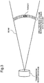
- Fig. 3 is a diagram illustrating an area for which volume reverberation is taken into account for detecting a target with pulse transmission.
- Fig. 4 is a diagram illustrating an area for which volume reverberation is taken into account for detecting a target with continuous transmission.
- the transmitter and the receiver are illustrated as one transmission reception device.
- the area for which volume reverberation is taken into account for detecting the target is a distance range approximately equal to a distance up to a position where the target in the medium exists (e.g., the surrounding area of an arc whose radius is this distance).
- reverberation scattering
- a scattered wave from the medium has larger influence when a distance from the medium is short than when a distance from the medium is long. For this reason, when an intensity level of a reflected wave from the target is buried in an intensity level of a scattered wave from the medium, the detector 4 of the target detection device 10 cannot detect a target.
- Fig. 5 is a diagram illustrating a detection distance range in the target detection device according to the first example embodiment.
- the transmitter and the receiver are illustrated as a transmission reception device.
- a short distance from the receiver, where a scattered wave gives large influence is assumed to be a lower limit distance r min
- a distance range from the receiver to the lower limit distance r min is assumed to be a masking region, and a region positioned farther than this distance range is assumed to be the detection distance range.
- the estimation unit 5 of the signal processing device 3 illustrated in Fig. 1 estimates the lower limit distance r min for a case where an intensity level of a scattered wave from the medium in the detection distance range illustrated in Fig. 5 is equal to or smaller than an allowable level at the detector 4 of the target detection device 10.
- the detection distance range is a distance range where a distance from the receiver of the transmission reception device is equal to or longer than the lower limit distance r min illustrated in Fig. 5 .
- Fig. 6 is a diagram illustrating directions of a transmission beam and a reception beam in a xyz coordinate system. It is assumed that in Fig. 6 , the transmitter and the receiver are arranged at the origin (0, 0, 0) of the xyz coordinates, and centers of the transmission beam and the reception beam are positioned on the x axis. It is assumed that the transmission beam and the reception beam are Gaussian beams, and the transmission beam and the reception beam have the same beam diameter.
- Fig. 7 is a diagram illustrating relation between the orthogonal coordinate system and the polar coordinate system.
- intensity of sound on the axis at a unit distance from the transmitter 1 is I 0 .
- Intensity I of sound incident on this minute volume is expressed as the expression (3).
- I I 0 B 2 r , ⁇ , ⁇ r 2
- Backward scattering intensity is a ratio of intensity of a scattered sound wave in an incident direction per a scattering layer unit volume, to an incident sound wave intensity.
- the receiver 2 receives this by the coordinate B 1 (r, ⁇ , ⁇ ) of the reception beam, and for this reason, output electric power at the receiver 2 is expressed as the expression (5) (response is assumed to be 1).
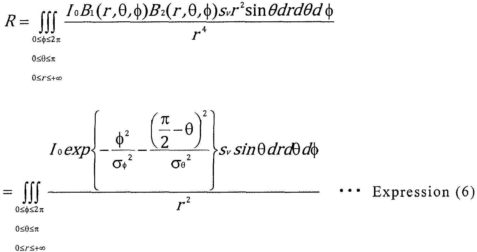
- a scattering intensity level R in an entire region (0 ⁇ r ⁇ + ⁇ ) can be acquired by integrating the expression (5).
- a scattering intensity level R' in the detection distance range where a distance r from the transmission-reception device is a distance (r min ⁇ r) equal to or longer than the lower limit distance r min is expressed as the expression (7).
- R ' ⁇ 0 ⁇ ⁇ ⁇ 2 ⁇ 0 ⁇ ⁇ ⁇ ⁇ r min ⁇ r ⁇ + ⁇ I 0 exp ⁇ ⁇ 2 ⁇ ⁇ 2 ⁇ ⁇ 2 ⁇ ⁇ 2 ⁇ ⁇ 2 s v sin ⁇ drd ⁇ d ⁇ r 2
- the integral as to ⁇ in the expression (7) is calculated as the expression (10) by the Taylor expansion of ⁇ in sin ⁇ , by taking into account the terms up to the third order of ⁇ , for example.
- ⁇ ⁇ ⁇ ⁇ exp ⁇ ⁇ 2 ⁇ ⁇ 2 ⁇ ⁇ 2 sin ⁇ d ⁇ ⁇ ⁇ ⁇ ⁇ ⁇ exp ⁇ ⁇ 2 ⁇ ⁇ 2 ⁇ ⁇ 2 ⁇ ⁇ 3 6 d ⁇ ⁇ 24 ⁇ ⁇ ⁇ 3 ⁇ ⁇ 2 ⁇ 6 ⁇ 3 / 2 ⁇ ⁇ 3 48
- a scattering intensity level R' in the detection distance range in the expression (7) can be expressed as the expression (11).
- the allowable scattering intensity level R a can be expressed as the expression (12), by using the lower limit distance r min .
- r min that is the lower limit distance of the detection distance range can be calculated by using ⁇ ⁇ , ⁇ ⁇ , I 0 , s v , and R a represented in the expression (13). r min ⁇ ⁇ 24 ⁇ ⁇ ⁇ 3 ⁇ ⁇ ⁇ ⁇ ⁇ 6 ⁇ 2 ⁇ ⁇ ⁇ ⁇ 3 I 0 S v 48 R a
- the estimation unit 5 can estimate an accurate lower limit distance r min by taking into account an absorption loss in the medium at the time of acquiring the lower limit distance r min .
- the scattering reduction unit 6 removes, from scattering from the medium from which the receiver 2 receives a wave, scattering from the medium in the masking region where a distance r from the receiver 2 satisfies 0 ⁇ r ⁇ r min . Thereby, when the detector 4 at a subsequent stage detects a target, an intensity level R' of scattering from the medium where a wave propagates in the detection distance range becomes equal to or smaller than the allowable scattering intensity level Ra.
- Scattering from the medium in the masking region (0 ⁇ r ⁇ r min ) is distinguished by varying a modulation condition between for the detection distance range having the lower limit distance r min and for the masking region.
- LFM linear frequency modulation
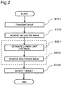
- Fig. 2 is a flowchart illustrating operation of the target detection device according to the first example embodiment.
- the transmitter 1 of the target detection device 10 continuously transmits a sound wave (a wave) toward a target in the water (S101).
- the receiver 2 of the target detection device 10 receives a reflected wave that a sound wave propagating through the water reflects in the medium (SI02).
- the reflected wave reflected in the medium also includes a scattered wave from the medium, besides a reflected wave from the target in the medium.
- the signal processing device 3 of the target detection device 10 removes an output of a scattered wave from the medium in the masking region to thereby reduce influence of scattering from the medium.
- the estimation unit 5 of the signal processing device 3 estimates a lower limit distance of a detection distance range for which an intensity level of a scattered wave from the medium in the detection distance range is equal to or smaller than an allowable level (S201). Further, the scattering reduction unit 6 of the signal processing device 3 removes, from a signal of the reflected wave received by the receiver 2, a signal of the scattered wave from the medium in the masking region from the receiver 2 to the lower limit distance (S202), and performs output.
- the detector 4 of the target detection device 10 Based on the output from the signal processing device 3, the detector 4 of the target detection device 10 then detects the target in the water.
- the target detection device in the first example embodiment is described above by citing an example of using a sound wave as a wave, but without limitation to this, a wave such as a radio wave or a light wave can be used.
- influence of scattering from the medium when a wave is continuously transmitted to detect a target, influence of scattering from the medium can be reduced.
- reduction in influence of scattering from the medium facilitates detection of a target in the medium.
- Fig. 8 is a diagram illustrating a hardware configuration for implementing, with a computer device, a signal processing device according to the first example embodiment.
- the signal processing device 3 is configured by hardware including a central processing unit (CPU) 91, a communication interface (communication I/F) 92 for network connection, a memory 93, and a storage device 94 such as a hard disk storing a program.
- the CPU 91 is coupled to an input device 95 and an output device 96 via a system bus 97.
- the CPU 91 causes an operating system to operate to execute predetermined processes in the estimation unit 5 and the scattering reduction unit 6 of the signal processing device 3 according to the first example embodiment.
- the CPU 91 reads out a program and data to the memory 93 from a recording medium attached to a drive device, for example.
- the CPU 91 includes a function of processing an information signal input from the receiver 2 and the like, and executes processes of various functions, based on the program, for example.
- the storage device 94 is an optical disk, a flexible disk, a magneto-optical disk, an external hard disk, a semiconductor memory, or the like, for example.
- a storage medium that is a part of the storage device 94 is a nonvolatile storage device, and a program is stored therein. The program may be downloaded from an external computer not illustrated, coupled to a communication network.
- the input device 95 is implemented by a mouse, a keyboard, built in key buttons, a touch panel, or the like, and is used for input operation.
- the output device 96 is implemented by, for example, a display, and is used for outputting and confirming information processed by the CPU 91, or the like.
- the signal processing device 3 is implemented by the hardware configuration illustrated in Fig. 8 .
- the signal processing device 3 may be implemented by one physically integrated device, or may be implemented by a plurality of devices with these two or more physically separated devices being coupled wirelessly or through a wired line.
Landscapes
- Engineering & Computer Science (AREA)
- Physics & Mathematics (AREA)
- Radar, Positioning & Navigation (AREA)
- Remote Sensing (AREA)
- Computer Networks & Wireless Communication (AREA)
- General Physics & Mathematics (AREA)
- Acoustics & Sound (AREA)
- Measurement Of Velocity Or Position Using Acoustic Or Ultrasonic Waves (AREA)
- Radar Systems Or Details Thereof (AREA)
- Optical Radar Systems And Details Thereof (AREA)
Abstract
Description
- The disclosed subject matter relates to a technology of detecting a target by using a wave such as a sound wave, a radio wave, or a light wave.
- A target detection device is known example of detecting a target by using a wave such as a sound wave, a radio wave, or a light wave, as in a sonar system, a radar system, or a lidar system. The system uses pulse transmission in which a transmitter transmits a wave, and after a lapse of predetermined time, transmits a wave again. Pulse transmission clarifies at which time point the wave corresponding to a reflected wave from the target is transmitted, and further, can remove influence due to scattering from a medium near the transmitter.
- In a case of continuously detecting a target, the transmitter continuously transmits a wave. In this case, in order to determine at which time point the wave corresponding to a reflected wave from the target is transmitted, the transmitter modulates and transmits a wave. In order to reduce influence of scattering from a medium near the transmitter, it is necessary to install a receiver and the transmitter at a predetermined distance apart, as described in
PTL 1, or to change a beam shape or a direction of a beam of the transmitter or the receiver by using adaptive beamforming. - However, when the transmitter and the receiver cannot be installed at a predetermined distance apart, influence of the scattering cannot be reduced sufficiently. In some cases, changing a beam shape does not cause to sufficiently reduce influence of the scattering. Further, in a case of changing a direction of a beam, a reflected wave from a target becomes small, and a target cannot be detected.
-
PTL 2 describes, as a method of avoiding influence of scattering from a medium, a method of separating from the scattering from the medium a reflected wave from a target by using Doppler shifting of a frequency of the reflected wave from the target in a case where the target is moving.PTL 3 describes that a covering state of a ground is recognized based on a difference between two scattered waves produced by reflection of two radio waves having different polarization properties. - Besides, the
PTL 4 describes, as a technology of avoiding influence of a scattered wave, a technology of irradiating a ground with a microwave to find correlation between a backward scattering coefficient of a radar image and a vegetation ground.PTL 5 describes a technology of changing transmission electric power of a modulated pulse signal, depending on a distance to a target, in order to avoid a reception signal failure due to a modulated pulse signal.PTL 6 describes a technology of separating a scattered wave from a mixed wave of a progressive wave advancing toward a target in a medium and a forward scattered wave scattered forward from the target, to search for the target. PTL 7 describes a technology of changing reception sensitivity, depending on delay time of reception, to detect a target by using an underground radar. -
- [PTL 1]:
U.S. Patent No. 7852709 - [PTL 2]: Japanese Patent No.
3367462 - [PTL 3]: Japanese Laid-open Patent Publication No.
2001-174545 - [PTL 4]: International Publication No.
WO 2010/055915 - [PTL 5]: Japanese Laid-open Patent Publication No.
2014-089212 - [PTL 6]: Japanese Laid-open Patent Publication No.
2010-008295 - [PTL 7]: Japanese Laid-open Patent Publication No.
2006-098112 - Reduction in scattering from a medium described in each of
PTLs PTLs 4 to 7 does not concern reduction in influence of scattering from a medium in a case of continuously transmitting a wave to detect a target. - An object of the disclosed subject matter is to provide a technology of reducing influence of scattering from a medium in a case of continuously transmitting a wave to detect a target.
- One aspect of a target detection device according to the disclosed subject matter includes:
- a transmission means for continuously transmitting a wave propagating through a medium;
- a reception means for receiving a reflected wave that the wave is reflected in the medium;
- a signal processing device configured to estimate a lower limit distance of a detection distance range for which an intensity level of a scattered wave from the medium in the detection distance range is equal to or smaller than an allowable level, and remove, from a signal of the reflected wave received by the reception means, a signal of a scattered wave from the medium in a masking region from the reception means to the lower limit distance to perform output; and
- a detection means for detecting a target in the medium, based on an output from the signal processing device.
- One aspect of a target detection method according to the disclosed subject matter includes:
- continuously transmitting a wave propagating through a medium;
- receiving a reflected wave that the wave is reflected in the medium;
- estimating a lower limit distance of a detection distance range for which an intensity level of a scattered wave from the medium in the detection distance range is equal to or smaller than an allowable level;
- removing, from a signal of the reflected wave received, a signal of a scattered wave from the medium in a masking region from a reception means to the lower limit distance to perform output; and
- detecting a target in the medium, based on the output.
- One aspect of a recording medium according to the disclosed subject matter, the recording medium storing a detection program that causes a computer to execute:
- continuously transmitting a wave propagating through a medium;
- receiving a reflected wave that the wave is reflected in the medium;
- estimating a lower limit distance of a detection distance range for which an intensity level of a scattered wave from the medium in the detection distance range is equal to or smaller than an allowable level;
- removing, from a signal of the reflected wave received, a signal of a scattered wave from the medium in a masking region from a reception means to the lower limit distance to perform output; and
- detecting a target in the medium, based on the output.
- One aspect of a signal processing device according to the disclosed subject matter, processes a signal of a reflected wave which is a wave reflected in a medium and is received by a reception means, when a wave propagating through the medium is continuously transmitted from a transmission means.
- The signal processing device includes:
- an estimation means for estimating a lower limit distance of a detection distance range for which an intensity level of a scattered wave from the medium in the detection distance range is equal to or smaller than an allowable level; and
- a scattering reduction means for removing, from a signal of the reflected wave received by the reception means, a signal of the scattered wave from the medium in a masking region from the reception means to the lower limit distance to perform output.
- One aspect of a signal processing method according to the disclosed subject matter, the signal processing method for processing a signal of a reflected wave which is a wave reflected in a medium and is received by a reception means, when a wave propagating through the medium is continuously transmitted from a transmission means.
- The signal processing method includes:
- estimating a lower limit distance of a detection distance range for which an intensity level of a scattered wave from the medium in the detection distance range is equal to or smaller than an allowable level; and
- removing, from a signal of the reflected wave received by the reception means, a signal of a scattered wave from the medium in a masking region from the reception means to the lower limit distance.
- One aspect of a recording medium according to the subject matter, the recording medium storing a signal processing program of processing a signal of a reflected wave which is a wave reflected in a medium and is received by a reception means, when a wave propagating through the medium is continuously transmitted from a transmission means.
- The signal processing program causing a computer to execute:
- estimating a lower limit distance of a detection distance range for which an intensity level of a scattered wave from the medium in the detection distance range is equal to or smaller than an allowable level; and
- removing, from a signal of the reflected wave received by the reception means, a signal of a scattered wave from the medium in a masking region from the reception means to the lower limit distance.
- According to the disclosed subject matter, in a case of continuously transmitting a wave to detect a target, influence of scattering from a medium can be reduced.
-
-
Fig. 1 is a block diagram illustrating a configuration of a signal processing device and a target detection device according to a first example embodiment. -
Fig. 2 is a flowchart illustrating operation of the target detection device according to the first example embodiment. -
Fig. 3 is a diagram illustrating an area for which volume reverberation is taken into account for detecting a target by pulse transmission. -
Fig. 4 is a diagram illustrating an area for which volume reverberation is taken into account for detecting a target by continuous transmission. -
Fig. 5 is a diagram illustrating a detection distance range in the target detection device according to the first example embodiment. -
Fig. 6 is a diagram illustrating directions of a transmission beam and a reception beam in an orthogonal coordinate system. -
Fig. 7 is a diagram illustrating relation between an orthogonal coordinate system and a polar coordinate system. -
Fig. 8 is a block diagram illustrating a hardware configuration of the signal processing device. - A signal processing device and a target detection device according to a first example embodiment will be described with reference to
Fig. 1 . The first example embodiment is an example of the target detection device that detects a target presenting in the water, by using a sound wave, and the signal processing device that is used in the target detection device. -
Fig. 1 is a block diagram illustrating a configuration of asignal processing device 3 and atarget detection device 10 according to the first example embodiment. Thetarget detection device 10 includes atransmitter 1, areceiver 2, thesignal processing device 3, and adetector 4. - The
transmitter 1 includes a function of continuously transmitting a sound wave toward a target in the water. The water can be called as a medium in other words. The sound wave can be also called as a wave. - The
receiver 2 includes a function of receiving a reflected wave that is a wave reflected in the medium when a sound wave propagates through the water. The reflected wave reflected in the medium includes not only the reflected wave from the target in the medium, but also a scattered wave from the medium. - The
signal processing device 3 includes a function of reducing influence of scattering from the medium in a masking region, on an output from thereceiver 2 that receives the reflected wave reflected in the medium (including the reflected wave from the target and the scattered wave from the medium). Here, the masking region is included in an area from which thereceiver 2 receives a scattered wave from the medium, and is a distance range up to a short distance from thereceiver 2 where a scattered wave gives large influence. An example of the distance range from thereceiver 2, defining the masking region, is described later along with description of the configuration of thesignal processing device 3. - The
detector 4 includes a function of detecting the target in the water, based on an output from thesignal processing device 3. - A configuration of the above described
transmitter 1,receiver 2, anddetector 4 is well known as a basic configuration of an active sonar device detecting a target in the water by using a sound wave. - Next, the
signal processing device 3 according to the first example embodiment is described in detail. As illustrated inFig. 1 , thesignal processing device 3 includes anestimation unit 5 and ascattering reduction unit 6. - In a case where an intensity level of a scattered wave from the medium in a detection distance range is equal to or smaller than an allowable level, a distance up to this medium is assumed to be a lower limit distance of the detection distance range. The
estimation unit 5 of thesignal processing device 3 includes a function of estimating the lower limit distance. Thescattering reduction unit 6 includes a function of removing, from a signal of a reflected wave received by thereceiver 2, a signal of a scattered wave from the medium in a masking region from thereceiver 2 to the lower limit distance. - Here, the detection distance range and the lower limit distance in the first example embodiment will be described.
Fig. 3 is a diagram illustrating an area for which volume reverberation is taken into account for detecting a target with pulse transmission.Fig. 4 is a diagram illustrating an area for which volume reverberation is taken into account for detecting a target with continuous transmission. InFig. 3 andFig. 4 , the transmitter and the receiver are illustrated as one transmission reception device. As illustrated inFig. 3 ,using pulse transmission, the area for which volume reverberation is taken into account for detecting the target is a distance range approximately equal to a distance up to a position where the target in the medium exists (e.g., the surrounding area of an arc whose radius is this distance). In contrast to this, when continuously transmitting a sound wave (Fig. 4 ) as in thetarget detection device 10 according to the first example embodiment, concerning the area for which volume reverberation is taken into account for detecting the target, reverberation (scattering) from an area other than a distance range near the target is also taken into account. A scattered wave from the medium has larger influence when a distance from the medium is short than when a distance from the medium is long. For this reason, when an intensity level of a reflected wave from the target is buried in an intensity level of a scattered wave from the medium, thedetector 4 of thetarget detection device 10 cannot detect a target. -
Fig. 5 is a diagram illustrating a detection distance range in the target detection device according to the first example embodiment. InFig. 5 , the transmitter and the receiver are illustrated as a transmission reception device. In thetarget detection device 10 according to the first example embodiment, a short distance from the receiver, where a scattered wave gives large influence, is assumed to be a lower limit distance rmin, a distance range from the receiver to the lower limit distance rmin is assumed to be a masking region, and a region positioned farther than this distance range is assumed to be the detection distance range. Theestimation unit 5 of thesignal processing device 3 illustrated inFig. 1 estimates the lower limit distance rmin for a case where an intensity level of a scattered wave from the medium in the detection distance range illustrated inFig. 5 is equal to or smaller than an allowable level at thedetector 4 of thetarget detection device 10. The detection distance range is a distance range where a distance from the receiver of the transmission reception device is equal to or longer than the lower limit distance rmin illustrated inFig. 5 . - A method of estimating a lower limit distance rmin is described in the following.
Fig. 6 is a diagram illustrating directions of a transmission beam and a reception beam in a xyz coordinate system. It is assumed that inFig. 6 , the transmitter and the receiver are arranged at the origin (0, 0, 0) of the xyz coordinates, and centers of the transmission beam and the reception beam are positioned on the x axis. It is assumed that the transmission beam and the reception beam are Gaussian beams, and the transmission beam and the reception beam have the same beam diameter. - Description is made by replacing the directions of the transmission beam and the reception beam illustrated by the orthogonal coordinate system in
Fig. 6 , with those in a polar coordinate system.Fig. 7 is a diagram illustrating relation between the orthogonal coordinate system and the polar coordinate system. Intensity B1(r,θ,ϕ) and B2(r,θ,ϕ) in the Gaussian distribution of the reception beam and the transmission beam expressed by the expression (1) and the expression (2), respectively, in the polar coordinate system.

(r: a distance from the origin, θ: an azimuth, ϕ: an angle of elevation, σθ: a standard deviation of a beam diameter at a certain azimuth, σϕ: a standard deviation of a beam diameter at a certain angle of elevation) - Meanwhile, it is assumed that intensity of sound on the axis at a unit distance from the
transmitter 1 is I0. - A minute volume at a polar coordinate (r,θ,ϕ) can be expressed as dr·rdθ·rsinθdϕ=r2sinθdrdθdϕ. Intensity I of sound incident on this minute volume is expressed as the expression (3).

- Expression of backward scattering intensity sv using decibel unit is Sv=10logsv (sv is also backward scattering intensity). Backward scattering intensity is a ratio of intensity of a scattered sound wave in an incident direction per a scattering layer unit volume, to an incident sound wave intensity. An intensity level of scattering at the reception point by a minute volume (=r2sinθdrdθdϕ) is expressed as the expression (4).

- The
receiver 2 receives this by the coordinate B1 (r,θ,ϕ) of the reception beam, and for this reason, output electric power at thereceiver 2 is expressed as the expression (5) (response is assumed to be 1).
- A scattering intensity level R in an entire region (0≤r≤+∞) can be acquired by integrating the expression (5).
- Here, a scattering intensity level R' in the detection distance range where a distance r from the transmission-reception device is a distance (rmin≤r) equal to or longer than the lower limit distance rmin is expressed as the expression (7).

- The integral as to r in the expression (7) is the expression (8).

- Here, the integral as to ϕ in the expression (7) is intended to be the integral over an entire circumference concerning the beam, and is replaced with the integral from -π to +π since the beam having the center at ϕ=0 is physically symmetrical with respect to ϕ=0. Further, the integral over -π≤ϕ<π which becomes separated from the center of an integral range is approximated as the integral over -∞<ϕ<∞ to result in the expression (9).

- The integral as to θ in the expression (7) is calculated as the expression (10) by the Taylor expansion of θ in sinθ, by taking into account the terms up to the third order of θ, for example.

- A scattering intensity level R' in the detection distance range in the expression (7) can be expressed as the expression (11).

- Since the scattering intensity level R' in the detection distance range is made equal to or smaller than a scattering intensity level Ra allowable for the detector in the target detection device, the allowable scattering intensity level Ra can be expressed as the expression (12), by using the lower limit distance rmin.

- Accordingly, rmin that is the lower limit distance of the detection distance range can be calculated by using σϕ, σθ, I0, sv, and Ra represented in the expression (13).

- The
estimation unit 5 can estimate an accurate lower limit distance rmin by taking into account an absorption loss in the medium at the time of acquiring the lower limit distance rmin. - The
scattering reduction unit 6 removes, from scattering from the medium from which thereceiver 2 receives a wave, scattering from the medium in the masking region where a distance r from thereceiver 2 satisfies 0≤r≤rmin. Thereby, when thedetector 4 at a subsequent stage detects a target, an intensity level R' of scattering from the medium where a wave propagates in the detection distance range becomes equal to or smaller than the allowable scattering intensity level Ra. - Scattering from the medium in the masking region (0≤r≤rmin) is distinguished by varying a modulation condition between for the detection distance range having the lower limit distance rmin and for the masking region. For example, the
scattering reduction unit 6 can perform the distinguishing from the intensity level R' of scattering from the detection distance range by using linear frequency modulation (LFM). Since a frequency of a transmission wave by the LFM is modulated to be in proportion to time, it is assumed that a frequency at the time t=0 is f=f0, and a transmission wave transmitted at the preceding time t=t1 by a frequency of f=f1 arrives at rmin. In this case, thescattering reduction unit 6 can remove scattering in a range of 0≤r≤rmin by removing a reflected wave having a frequency in a range of f1≤f≤f0. - Although the description is made above by using the LFM as an example of varying a modulation condition in order to remove scattering from the medium in the masking region, a different frequency modulation may be used. Scattering from the medium in the masking region can be removed also by using different modulation information such as phase modulation or amplitude modulation other than frequency modulation.
- Next, operation of the target detection device according to the first example embodiment is described by using the drawing.
Fig. 2 is a flowchart illustrating operation of the target detection device according to the first example embodiment. As illustrated inFig. 1 andFig. 2 , thetransmitter 1 of thetarget detection device 10 continuously transmits a sound wave (a wave) toward a target in the water (S101). Next, thereceiver 2 of thetarget detection device 10 receives a reflected wave that a sound wave propagating through the water reflects in the medium (SI02). The reflected wave reflected in the medium also includes a scattered wave from the medium, besides a reflected wave from the target in the medium. - Next, based on an output from the
receiver 2 that has received the reflected wave reflected in the medium, thesignal processing device 3 of thetarget detection device 10 removes an output of a scattered wave from the medium in the masking region to thereby reduce influence of scattering from the medium. - Specifically, the
estimation unit 5 of thesignal processing device 3 estimates a lower limit distance of a detection distance range for which an intensity level of a scattered wave from the medium in the detection distance range is equal to or smaller than an allowable level (S201). Further, thescattering reduction unit 6 of thesignal processing device 3 removes, from a signal of the reflected wave received by thereceiver 2, a signal of the scattered wave from the medium in the masking region from thereceiver 2 to the lower limit distance (S202), and performs output. - Based on the output from the
signal processing device 3, thedetector 4 of thetarget detection device 10 then detects the target in the water. - The target detection device in the first example embodiment is described above by citing an example of using a sound wave as a wave, but without limitation to this, a wave such as a radio wave or a light wave can be used.
- According to the signal processing device of the first example embodiment, when a wave is continuously transmitted to detect a target, influence of scattering from the medium can be reduced. According to the target detection device of the first example embodiment, reduction in influence of scattering from the medium facilitates detection of a target in the medium.
-
Fig. 8 is a diagram illustrating a hardware configuration for implementing, with a computer device, a signal processing device according to the first example embodiment. Thesignal processing device 3 is configured by hardware including a central processing unit (CPU) 91, a communication interface (communication I/F) 92 for network connection, amemory 93, and astorage device 94 such as a hard disk storing a program. TheCPU 91 is coupled to aninput device 95 and anoutput device 96 via asystem bus 97. - The
CPU 91 causes an operating system to operate to execute predetermined processes in theestimation unit 5 and thescattering reduction unit 6 of thesignal processing device 3 according to the first example embodiment. TheCPU 91 reads out a program and data to thememory 93 from a recording medium attached to a drive device, for example. TheCPU 91 includes a function of processing an information signal input from thereceiver 2 and the like, and executes processes of various functions, based on the program, for example. - The
storage device 94 is an optical disk, a flexible disk, a magneto-optical disk, an external hard disk, a semiconductor memory, or the like, for example. A storage medium that is a part of thestorage device 94 is a nonvolatile storage device, and a program is stored therein. The program may be downloaded from an external computer not illustrated, coupled to a communication network. - The
input device 95 is implemented by a mouse, a keyboard, built in key buttons, a touch panel, or the like, and is used for input operation. Theoutput device 96 is implemented by, for example, a display, and is used for outputting and confirming information processed by theCPU 91, or the like. - As described above, the
signal processing device 3 according to the first example embodiment is implemented by the hardware configuration illustrated inFig. 8 . Thesignal processing device 3 may be implemented by one physically integrated device, or may be implemented by a plurality of devices with these two or more physically separated devices being coupled wirelessly or through a wired line. - Although the disclosed subject matter is described above with reference to the example embodiments (and the examples), the disclosed subject matter is not limited to the above described example embodiments (and the examples). Various modifications that can be understood by those skilled in the art can be made on a configuration and details of the disclosed subject matter, within the scope of the disclosed subject matter.
- The present application claims priority based on Japanese Patent Application No.
2015-029224 filed on February 18, 2015 -
- 1
- Transmitter
- 2
- Receiver
- 3
- Signal processing device
- 4
- Detector
- 5
- Estimation unit
- 6
- Scattering reduction unit
- 10
- Target detection device
- 91
- CPU
- 92
- Communication I/F (communication interface)
- 93
- Memory
- 94
- Storage device
- 95
- Input device
- 96
- Output device
- 97
- System bus
Claims (9)
- A target detection device comprising:a transmission means for continuously transmitting a wave propagating through a medium;a reception means for receiving a reflected wave that the wave is reflected in the medium;a signal processing device configured to estimate a lower limit distance of a detection distance range for which an intensity level of a scattered wave from the medium in the detection distance range is equal to or smaller than an allowable level, and remove, from a signal of the reflected wave received by the reception means, a signal of a scattered wave from the medium in a masking region from the reception means to the lower limit distance to perform output; anda detection means for detecting a target in the medium, based on an output from the signal processing device.
- The target detection device according to claim 1,
wherein the transmission means performs frequency modulation, phase modulation, or amplitude modulation to transmit the wave, and
based on modulation information of the reflected wave received by the reception means, wherein the signal processing device removes, from a signal of the reflected wave received by the reception means, a signal of a scattered wave from the medium in the masking region. - The target detection device according to claim 1 or 2, wherein the transmission means transmits a wave by linear frequency modulation.
- The target detection device according to claim 1 or 2, wherein a wave transmitted by the transmission means is one of a sound wave, a radio wave, and a light wave.
- A target detection method comprising:continuously transmitting a wave propagating through a medium;receiving a reflected wave that the wave is reflected in the medium;estimating a lower limit distance of a detection distance range for which an intensity level of a scattered wave from the medium in the detection distance range is equal to or smaller than an allowable level;removing, from a signal of the reflected wave received, a signal of a scattered wave from the medium in a masking region from a reception means to the lower limit distance to perform output; anddetecting a target in the medium, based on the output.
- A recording medium storing a detection program that causes a computer to execute:continuously transmitting a wave propagating through a medium;receiving a reflected wave that the wave is reflected in the medium;estimating a lower limit distance of a detection distance range for which an intensity level of a scattered wave from the medium in the detection distance range is equal to or smaller than an allowable level;removing, from a signal of the reflected wave received, a signal of a scattered wave from the medium in a masking region from a reception means to the lower limit distance to perform output; anddetecting a target in the medium, based on the output.
- A signal processing device for processing a signal of a reflected wave which is a wave reflected in a medium and is received by a reception means, when a wave propagating through the medium and is continuously transmitted from a transmission means, the signal processing device comprising:an estimation means for estimating a lower limit distance of a detection distance range for which an intensity level of a scattered wave from the medium in the detection distance range is equal to or smaller than an allowable level; anda scattering reduction means for removing, from a signal of the reflected wave received by the reception means, a signal of the scattered wave from the medium in a masking region from the reception means to the lower limit distance to perform output.
- A signal processing method for processing a signal of a reflected wave which is a wave reflected in a medium and is received by a reception means, when a wave propagating through the medium is continuously transmitted from a transmission means, the signal processing method comprising:estimating a lower limit distance of a detection distance range for which an intensity level of a scattered wave from the medium in the detection distance range is equal to or smaller than an allowable level; andremoving, from a signal of the reflected wave received by the reception means, a signal of a scattered wave from the medium in a masking region from the reception means to the lower limit distance.
- A recording medium storing a signal processing program of processing a signal of a reflected wave which and a reflected wave is a wave reflected in a medium and is received by a reception means, when a wave propagating through the medium is continuously transmitted from a transmission means, the signal processing program causing a computer to execute:estimating a lower limit distance of a detection distance range for which an intensity level of a scattered wave from the medium in the detection distance range is equal to or smaller than an allowable level; andremoving, from a signal of the reflected wave received by the reception means, a signal of a scattered wave from the medium in a masking region from the reception means to the lower limit distance.
Applications Claiming Priority (2)
| Application Number | Priority Date | Filing Date | Title |
|---|---|---|---|
| JP2015029224 | 2015-02-18 | ||
| PCT/JP2016/000878 WO2016132742A1 (en) | 2015-02-18 | 2016-02-18 | Signal-processing device and processing method, recording medium, and target detection device and detection method |
Publications (3)
| Publication Number | Publication Date |
|---|---|
| EP3260880A1 true EP3260880A1 (en) | 2017-12-27 |
| EP3260880A4 EP3260880A4 (en) | 2018-10-17 |
| EP3260880B1 EP3260880B1 (en) | 2023-08-23 |
Family
ID=56692180
Family Applications (1)
| Application Number | Title | Priority Date | Filing Date |
|---|---|---|---|
| EP16752131.9A Active EP3260880B1 (en) | 2015-02-18 | 2016-02-18 | Signal-processing device and processing method, recording medium, and target detection device and detection method |
Country Status (5)
| Country | Link |
|---|---|
| US (1) | US10761185B2 (en) |
| EP (1) | EP3260880B1 (en) |
| JP (1) | JP6485538B2 (en) |
| CA (1) | CA2977200C (en) |
| WO (1) | WO2016132742A1 (en) |
Families Citing this family (3)
| Publication number | Priority date | Publication date | Assignee | Title |
|---|---|---|---|---|
| JP6610977B2 (en) * | 2016-03-24 | 2019-11-27 | 日本電気株式会社 | Target detection system, method and program |
| CN114624682B (en) * | 2022-05-17 | 2022-09-30 | 中国科学技术大学 | Method and system for suppressing near field strength echo signal |
| EP4591418A1 (en) * | 2022-09-21 | 2025-07-30 | Reach Power, Inc. | System and method for wireless power transmission and/or field detection |
Family Cites Families (20)
| Publication number | Priority date | Publication date | Assignee | Title |
|---|---|---|---|---|
| DE3425098C2 (en) * | 1984-07-07 | 1986-11-06 | Messerschmitt-Bölkow-Blohm GmbH, 8012 Ottobrunn | Device for capturing, distance measuring and imaging objects in enveloping cloudy media by means of laser |
| JPH0432628Y2 (en) * | 1986-06-20 | 1992-08-05 | ||
| JPH083530B2 (en) * | 1989-03-13 | 1996-01-17 | 日本電気株式会社 | Water depth measuring device |
| JPH1010233A (en) * | 1996-06-24 | 1998-01-16 | Mitsui Eng & Shipbuild Co Ltd | Laser type obstacle detection method and sensor |
| DE19704220A1 (en) * | 1997-02-05 | 1998-08-06 | Ingbuero Spies | Method and device for determining a distance between vehicle and obstacle |
| JP3367462B2 (en) | 1999-04-20 | 2003-01-14 | 日本電気株式会社 | Active sonar and target detection method thereof |
| JP2001174545A (en) | 1999-12-15 | 2001-06-29 | Nec Network Sensa Kk | Underwater stationary object detecting method and device |
| JP2002181954A (en) * | 2000-07-05 | 2002-06-26 | Osaka Gas Co Ltd | Concealed object probing method and device |
| EP1692542A4 (en) | 2003-09-29 | 2011-03-30 | Ac Capital Man Inc | Sonar system and process |
| WO2006009469A2 (en) | 2004-07-23 | 2006-01-26 | Angelsen Bjoern A J | Ultrasound imaging using non-linear manipulation of forward propagation |
| JP2006098112A (en) | 2004-09-28 | 2006-04-13 | Kddi Corp | Ground penetrating radar image processing method |
| US20110002191A1 (en) * | 2006-12-07 | 2011-01-06 | Alion Science & Technology | Active sonar apparatuses and methods |
| JP5110529B2 (en) | 2008-06-27 | 2012-12-26 | 日本電気株式会社 | Target search device, target search program, and target search method |
| JP5369282B2 (en) | 2008-11-14 | 2013-12-18 | 株式会社パスコ | Vegetation growth situation analysis method, program, and vegetation growth situation analysis apparatus |
| US8184276B2 (en) * | 2008-12-08 | 2012-05-22 | Carl Embry | Continuous index of refraction compensation method for measurements in a medium |
| JP5682965B2 (en) * | 2011-10-18 | 2015-03-11 | オムロンオートモーティブエレクトロニクス株式会社 | Vehicle detection device, communication device, and vehicle detection system |
| JP6021324B2 (en) * | 2011-12-13 | 2016-11-09 | 三菱電機株式会社 | Laser radar equipment |
| JP2013178170A (en) * | 2012-02-28 | 2013-09-09 | Mitsubishi Heavy Ind Ltd | Underwater sailing body and acquisition method of water bottom depth of underwater sailing body |
| JP6264194B2 (en) * | 2013-06-11 | 2018-01-24 | 三菱電機株式会社 | Radar equipment |
| JP5746776B2 (en) | 2014-01-14 | 2015-07-08 | 日本無線株式会社 | Target detection device |
-
2016
- 2016-02-18 EP EP16752131.9A patent/EP3260880B1/en active Active
- 2016-02-18 WO PCT/JP2016/000878 patent/WO2016132742A1/en not_active Ceased
- 2016-02-18 JP JP2017500526A patent/JP6485538B2/en active Active
- 2016-02-18 US US15/549,422 patent/US10761185B2/en active Active
- 2016-02-18 CA CA2977200A patent/CA2977200C/en active Active
Also Published As
| Publication number | Publication date |
|---|---|
| CA2977200C (en) | 2021-04-13 |
| EP3260880B1 (en) | 2023-08-23 |
| WO2016132742A1 (en) | 2016-08-25 |
| EP3260880A4 (en) | 2018-10-17 |
| US10761185B2 (en) | 2020-09-01 |
| JPWO2016132742A1 (en) | 2017-12-21 |
| CA2977200A1 (en) | 2016-08-25 |
| JP6485538B2 (en) | 2019-03-20 |
| US20180024227A1 (en) | 2018-01-25 |
Similar Documents
| Publication | Publication Date | Title |
|---|---|---|
| US11099269B2 (en) | Radar device for vehicle and target determination method therefor | |
| US10401487B2 (en) | Radar device for vehicle and target measurement method therefor | |
| US9952312B2 (en) | Radar interference mitigation | |
| US20180341012A1 (en) | Ghost removal method and radar device | |
| US10795017B2 (en) | Dual polarization radar apparatus and radar signal processing method | |
| US11300657B2 (en) | Apparatus of generating jamming signal for deceiving transmission/reception device and method thereof | |
| EP2902799A1 (en) | Doppler radar test system | |
| JP2008275460A (en) | Radar equipment | |
| EP3451015B1 (en) | Method and apparatus for detecting object using radar of vehicle | |
| US10234548B2 (en) | Ultrasonic detection device to determine interference source by an additional reception mode | |
| EP3260880B1 (en) | Signal-processing device and processing method, recording medium, and target detection device and detection method | |
| US9841497B2 (en) | Method, device and system for processing radar signals | |
| KR101184622B1 (en) | Apparatus and method for avoiding interference among car radars based on fmcw waveform | |
| CN107076831B (en) | Radar sensor | |
| JPWO2007094064A1 (en) | Radar equipment | |
| JP6264194B2 (en) | Radar equipment | |
| EP3153880B1 (en) | Target detection device | |
| EP3623841A1 (en) | Object detection device | |
| JP5574907B2 (en) | Radar equipment | |
| KR20140064489A (en) | Target recognition based on track information | |
| KR20170036384A (en) | RADAR apparatus, apparatus and method for controlling RADAR | |
| JP2015034725A (en) | Rader apparatus | |
| WO2020170690A1 (en) | Radar control device, radar control method, and program | |
| JP6311230B2 (en) | Target detection apparatus, target detection method, program, and recording medium | |
| JP2015184148A (en) | Dme ground device and method for preventing stoppage of operation |
Legal Events
| Date | Code | Title | Description |
|---|---|---|---|
| STAA | Information on the status of an ep patent application or granted ep patent |
Free format text: STATUS: THE INTERNATIONAL PUBLICATION HAS BEEN MADE |
|
| PUAI | Public reference made under article 153(3) epc to a published international application that has entered the european phase |
Free format text: ORIGINAL CODE: 0009012 |
|
| STAA | Information on the status of an ep patent application or granted ep patent |
Free format text: STATUS: REQUEST FOR EXAMINATION WAS MADE |
|
| 17P | Request for examination filed |
Effective date: 20170918 |
|
| AK | Designated contracting states |
Kind code of ref document: A1 Designated state(s): AL AT BE BG CH CY CZ DE DK EE ES FI FR GB GR HR HU IE IS IT LI LT LU LV MC MK MT NL NO PL PT RO RS SE SI SK SM TR |
|
| AX | Request for extension of the european patent |
Extension state: BA ME |
|
| DAV | Request for validation of the european patent (deleted) | ||
| DAX | Request for extension of the european patent (deleted) | ||
| A4 | Supplementary search report drawn up and despatched |
Effective date: 20180919 |
|
| RIC1 | Information provided on ipc code assigned before grant |
Ipc: G01S 7/497 20060101ALN20180911BHEP Ipc: G01S 15/34 20060101AFI20180911BHEP Ipc: G01S 7/493 20060101ALN20180911BHEP Ipc: G01S 7/40 20060101ALN20180911BHEP Ipc: G01S 7/35 20060101ALN20180911BHEP Ipc: G01S 7/52 20060101ALI20180911BHEP Ipc: G01S 13/34 20060101ALN20180911BHEP Ipc: G01S 17/32 20060101ALN20180911BHEP Ipc: G01S 7/536 20060101ALI20180911BHEP |
|
| STAA | Information on the status of an ep patent application or granted ep patent |
Free format text: STATUS: EXAMINATION IS IN PROGRESS |
|
| 17Q | First examination report despatched |
Effective date: 20210422 |
|
| REG | Reference to a national code |
Ref country code: DE Ref legal event code: R079 Free format text: PREVIOUS MAIN CLASS: G01S0007526000 Ipc: G01S0015340000 Ref document number: 602016082134 Country of ref document: DE |
|
| GRAP | Despatch of communication of intention to grant a patent |
Free format text: ORIGINAL CODE: EPIDOSNIGR1 |
|
| STAA | Information on the status of an ep patent application or granted ep patent |
Free format text: STATUS: GRANT OF PATENT IS INTENDED |
|
| RIC1 | Information provided on ipc code assigned before grant |
Ipc: G01S 13/34 20060101ALN20230213BHEP Ipc: G01S 7/497 20060101ALN20230213BHEP Ipc: G01S 7/493 20060101ALN20230213BHEP Ipc: G01S 7/40 20060101ALN20230213BHEP Ipc: G01S 7/35 20060101ALN20230213BHEP Ipc: G01S 17/32 20060101ALN20230213BHEP Ipc: G01S 7/536 20060101ALI20230213BHEP Ipc: G01S 7/52 20060101ALI20230213BHEP Ipc: G01S 15/34 20060101AFI20230213BHEP |
|
| INTG | Intention to grant announced |
Effective date: 20230310 |
|
| GRAS | Grant fee paid |
Free format text: ORIGINAL CODE: EPIDOSNIGR3 |
|
| GRAA | (expected) grant |
Free format text: ORIGINAL CODE: 0009210 |
|
| STAA | Information on the status of an ep patent application or granted ep patent |
Free format text: STATUS: THE PATENT HAS BEEN GRANTED |
|
| AK | Designated contracting states |
Kind code of ref document: B1 Designated state(s): AL AT BE BG CH CY CZ DE DK EE ES FI FR GB GR HR HU IE IS IT LI LT LU LV MC MK MT NL NO PL PT RO RS SE SI SK SM TR |
|
| REG | Reference to a national code |
Ref country code: GB Ref legal event code: FG4D |
|
| REG | Reference to a national code |
Ref country code: CH Ref legal event code: EP |
|
| REG | Reference to a national code |
Ref country code: IE Ref legal event code: FG4D |
|
| REG | Reference to a national code |
Ref country code: DE Ref legal event code: R096 Ref document number: 602016082134 Country of ref document: DE |
|
| REG | Reference to a national code |
Ref country code: LT Ref legal event code: MG9D |
|
| REG | Reference to a national code |
Ref country code: NL Ref legal event code: MP Effective date: 20230823 |
|
| REG | Reference to a national code |
Ref country code: AT Ref legal event code: MK05 Ref document number: 1603234 Country of ref document: AT Kind code of ref document: T Effective date: 20230823 |
|
| PG25 | Lapsed in a contracting state [announced via postgrant information from national office to epo] |
Ref country code: GR Free format text: LAPSE BECAUSE OF FAILURE TO SUBMIT A TRANSLATION OF THE DESCRIPTION OR TO PAY THE FEE WITHIN THE PRESCRIBED TIME-LIMIT Effective date: 20231124 |
|
| PG25 | Lapsed in a contracting state [announced via postgrant information from national office to epo] |
Ref country code: IS Free format text: LAPSE BECAUSE OF FAILURE TO SUBMIT A TRANSLATION OF THE DESCRIPTION OR TO PAY THE FEE WITHIN THE PRESCRIBED TIME-LIMIT Effective date: 20231223 |
|
| PG25 | Lapsed in a contracting state [announced via postgrant information from national office to epo] |
Ref country code: SE Free format text: LAPSE BECAUSE OF FAILURE TO SUBMIT A TRANSLATION OF THE DESCRIPTION OR TO PAY THE FEE WITHIN THE PRESCRIBED TIME-LIMIT Effective date: 20230823 Ref country code: RS Free format text: LAPSE BECAUSE OF FAILURE TO SUBMIT A TRANSLATION OF THE DESCRIPTION OR TO PAY THE FEE WITHIN THE PRESCRIBED TIME-LIMIT Effective date: 20230823 Ref country code: PT Free format text: LAPSE BECAUSE OF FAILURE TO SUBMIT A TRANSLATION OF THE DESCRIPTION OR TO PAY THE FEE WITHIN THE PRESCRIBED TIME-LIMIT Effective date: 20231226 Ref country code: NO Free format text: LAPSE BECAUSE OF FAILURE TO SUBMIT A TRANSLATION OF THE DESCRIPTION OR TO PAY THE FEE WITHIN THE PRESCRIBED TIME-LIMIT Effective date: 20231123 Ref country code: NL Free format text: LAPSE BECAUSE OF FAILURE TO SUBMIT A TRANSLATION OF THE DESCRIPTION OR TO PAY THE FEE WITHIN THE PRESCRIBED TIME-LIMIT Effective date: 20230823 Ref country code: LV Free format text: LAPSE BECAUSE OF FAILURE TO SUBMIT A TRANSLATION OF THE DESCRIPTION OR TO PAY THE FEE WITHIN THE PRESCRIBED TIME-LIMIT Effective date: 20230823 Ref country code: LT Free format text: LAPSE BECAUSE OF FAILURE TO SUBMIT A TRANSLATION OF THE DESCRIPTION OR TO PAY THE FEE WITHIN THE PRESCRIBED TIME-LIMIT Effective date: 20230823 Ref country code: IS Free format text: LAPSE BECAUSE OF FAILURE TO SUBMIT A TRANSLATION OF THE DESCRIPTION OR TO PAY THE FEE WITHIN THE PRESCRIBED TIME-LIMIT Effective date: 20231223 Ref country code: HR Free format text: LAPSE BECAUSE OF FAILURE TO SUBMIT A TRANSLATION OF THE DESCRIPTION OR TO PAY THE FEE WITHIN THE PRESCRIBED TIME-LIMIT Effective date: 20230823 Ref country code: GR Free format text: LAPSE BECAUSE OF FAILURE TO SUBMIT A TRANSLATION OF THE DESCRIPTION OR TO PAY THE FEE WITHIN THE PRESCRIBED TIME-LIMIT Effective date: 20231124 Ref country code: FI Free format text: LAPSE BECAUSE OF FAILURE TO SUBMIT A TRANSLATION OF THE DESCRIPTION OR TO PAY THE FEE WITHIN THE PRESCRIBED TIME-LIMIT Effective date: 20230823 Ref country code: AT Free format text: LAPSE BECAUSE OF FAILURE TO SUBMIT A TRANSLATION OF THE DESCRIPTION OR TO PAY THE FEE WITHIN THE PRESCRIBED TIME-LIMIT Effective date: 20230823 |
|
| PG25 | Lapsed in a contracting state [announced via postgrant information from national office to epo] |
Ref country code: PL Free format text: LAPSE BECAUSE OF FAILURE TO SUBMIT A TRANSLATION OF THE DESCRIPTION OR TO PAY THE FEE WITHIN THE PRESCRIBED TIME-LIMIT Effective date: 20230823 |
|
| PG25 | Lapsed in a contracting state [announced via postgrant information from national office to epo] |
Ref country code: ES Free format text: LAPSE BECAUSE OF FAILURE TO SUBMIT A TRANSLATION OF THE DESCRIPTION OR TO PAY THE FEE WITHIN THE PRESCRIBED TIME-LIMIT Effective date: 20230823 |
|
| PG25 | Lapsed in a contracting state [announced via postgrant information from national office to epo] |
Ref country code: SM Free format text: LAPSE BECAUSE OF FAILURE TO SUBMIT A TRANSLATION OF THE DESCRIPTION OR TO PAY THE FEE WITHIN THE PRESCRIBED TIME-LIMIT Effective date: 20230823 Ref country code: RO Free format text: LAPSE BECAUSE OF FAILURE TO SUBMIT A TRANSLATION OF THE DESCRIPTION OR TO PAY THE FEE WITHIN THE PRESCRIBED TIME-LIMIT Effective date: 20230823 Ref country code: ES Free format text: LAPSE BECAUSE OF FAILURE TO SUBMIT A TRANSLATION OF THE DESCRIPTION OR TO PAY THE FEE WITHIN THE PRESCRIBED TIME-LIMIT Effective date: 20230823 Ref country code: EE Free format text: LAPSE BECAUSE OF FAILURE TO SUBMIT A TRANSLATION OF THE DESCRIPTION OR TO PAY THE FEE WITHIN THE PRESCRIBED TIME-LIMIT Effective date: 20230823 Ref country code: DK Free format text: LAPSE BECAUSE OF FAILURE TO SUBMIT A TRANSLATION OF THE DESCRIPTION OR TO PAY THE FEE WITHIN THE PRESCRIBED TIME-LIMIT Effective date: 20230823 Ref country code: CZ Free format text: LAPSE BECAUSE OF FAILURE TO SUBMIT A TRANSLATION OF THE DESCRIPTION OR TO PAY THE FEE WITHIN THE PRESCRIBED TIME-LIMIT Effective date: 20230823 Ref country code: SK Free format text: LAPSE BECAUSE OF FAILURE TO SUBMIT A TRANSLATION OF THE DESCRIPTION OR TO PAY THE FEE WITHIN THE PRESCRIBED TIME-LIMIT Effective date: 20230823 |
|
| REG | Reference to a national code |
Ref country code: DE Ref legal event code: R097 Ref document number: 602016082134 Country of ref document: DE |
|
| PG25 | Lapsed in a contracting state [announced via postgrant information from national office to epo] |
Ref country code: IT Free format text: LAPSE BECAUSE OF FAILURE TO SUBMIT A TRANSLATION OF THE DESCRIPTION OR TO PAY THE FEE WITHIN THE PRESCRIBED TIME-LIMIT Effective date: 20230823 |
|
| PLBE | No opposition filed within time limit |
Free format text: ORIGINAL CODE: 0009261 |
|
| STAA | Information on the status of an ep patent application or granted ep patent |
Free format text: STATUS: NO OPPOSITION FILED WITHIN TIME LIMIT |
|
| 26N | No opposition filed |
Effective date: 20240524 |
|
| PG25 | Lapsed in a contracting state [announced via postgrant information from national office to epo] |
Ref country code: SI Free format text: LAPSE BECAUSE OF FAILURE TO SUBMIT A TRANSLATION OF THE DESCRIPTION OR TO PAY THE FEE WITHIN THE PRESCRIBED TIME-LIMIT Effective date: 20230823 |
|
| PG25 | Lapsed in a contracting state [announced via postgrant information from national office to epo] |
Ref country code: MC Free format text: LAPSE BECAUSE OF FAILURE TO SUBMIT A TRANSLATION OF THE DESCRIPTION OR TO PAY THE FEE WITHIN THE PRESCRIBED TIME-LIMIT Effective date: 20230823 |
|
| REG | Reference to a national code |
Ref country code: CH Ref legal event code: PL |
|
| PG25 | Lapsed in a contracting state [announced via postgrant information from national office to epo] |
Ref country code: LU Free format text: LAPSE BECAUSE OF NON-PAYMENT OF DUE FEES Effective date: 20240218 |
|
| PG25 | Lapsed in a contracting state [announced via postgrant information from national office to epo] |
Ref country code: CH Free format text: LAPSE BECAUSE OF NON-PAYMENT OF DUE FEES Effective date: 20240229 |
|
| PG25 | Lapsed in a contracting state [announced via postgrant information from national office to epo] |
Ref country code: LU Free format text: LAPSE BECAUSE OF NON-PAYMENT OF DUE FEES Effective date: 20240218 Ref country code: CH Free format text: LAPSE BECAUSE OF NON-PAYMENT OF DUE FEES Effective date: 20240229 |
|
| PG25 | Lapsed in a contracting state [announced via postgrant information from national office to epo] |
Ref country code: BG Free format text: LAPSE BECAUSE OF FAILURE TO SUBMIT A TRANSLATION OF THE DESCRIPTION OR TO PAY THE FEE WITHIN THE PRESCRIBED TIME-LIMIT Effective date: 20230823 |
|
| PG25 | Lapsed in a contracting state [announced via postgrant information from national office to epo] |
Ref country code: BG Free format text: LAPSE BECAUSE OF FAILURE TO SUBMIT A TRANSLATION OF THE DESCRIPTION OR TO PAY THE FEE WITHIN THE PRESCRIBED TIME-LIMIT Effective date: 20230823 |
|
| REG | Reference to a national code |
Ref country code: BE Ref legal event code: MM Effective date: 20240229 |
|
| PG25 | Lapsed in a contracting state [announced via postgrant information from national office to epo] |
Ref country code: BE Free format text: LAPSE BECAUSE OF NON-PAYMENT OF DUE FEES Effective date: 20240229 |
|
| PG25 | Lapsed in a contracting state [announced via postgrant information from national office to epo] |
Ref country code: IE Free format text: LAPSE BECAUSE OF NON-PAYMENT OF DUE FEES Effective date: 20240218 |
|
| PG25 | Lapsed in a contracting state [announced via postgrant information from national office to epo] |
Ref country code: IE Free format text: LAPSE BECAUSE OF NON-PAYMENT OF DUE FEES Effective date: 20240218 Ref country code: BE Free format text: LAPSE BECAUSE OF NON-PAYMENT OF DUE FEES Effective date: 20240229 |
|
| PG25 | Lapsed in a contracting state [announced via postgrant information from national office to epo] |
Ref country code: CY Free format text: LAPSE BECAUSE OF FAILURE TO SUBMIT A TRANSLATION OF THE DESCRIPTION OR TO PAY THE FEE WITHIN THE PRESCRIBED TIME-LIMIT; INVALID AB INITIO Effective date: 20160218 |
|
| PG25 | Lapsed in a contracting state [announced via postgrant information from national office to epo] |
Ref country code: HU Free format text: LAPSE BECAUSE OF FAILURE TO SUBMIT A TRANSLATION OF THE DESCRIPTION OR TO PAY THE FEE WITHIN THE PRESCRIBED TIME-LIMIT; INVALID AB INITIO Effective date: 20160218 |
|
| PG25 | Lapsed in a contracting state [announced via postgrant information from national office to epo] |
Ref country code: TR Free format text: LAPSE BECAUSE OF FAILURE TO SUBMIT A TRANSLATION OF THE DESCRIPTION OR TO PAY THE FEE WITHIN THE PRESCRIBED TIME-LIMIT Effective date: 20230823 |
|
| PGFP | Annual fee paid to national office [announced via postgrant information from national office to epo] |
Ref country code: GB Payment date: 20260219 Year of fee payment: 11 |
|
| PGFP | Annual fee paid to national office [announced via postgrant information from national office to epo] |
Ref country code: DE Payment date: 20260218 Year of fee payment: 11 |
|
| PGFP | Annual fee paid to national office [announced via postgrant information from national office to epo] |
Ref country code: FR Payment date: 20260218 Year of fee payment: 11 |