EP3260879A1 - Method and system for trailer detection - Google Patents
Method and system for trailer detection Download PDFInfo
- Publication number
- EP3260879A1 EP3260879A1 EP17174842.9A EP17174842A EP3260879A1 EP 3260879 A1 EP3260879 A1 EP 3260879A1 EP 17174842 A EP17174842 A EP 17174842A EP 3260879 A1 EP3260879 A1 EP 3260879A1
- Authority
- EP
- European Patent Office
- Prior art keywords
- trailer
- vehicle
- host
- angle
- radar
- Prior art date
- Legal status (The legal status is an assumption and is not a legal conclusion. Google has not performed a legal analysis and makes no representation as to the accuracy of the status listed.)
- Withdrawn
Links
- 238000001514 detection method Methods 0.000 title claims abstract description 15
- 238000000034 method Methods 0.000 title claims description 27
- 238000004891 communication Methods 0.000 claims abstract description 5
- 230000003213 activating effect Effects 0.000 claims description 3
- 230000006872 improvement Effects 0.000 description 6
- 230000008901 benefit Effects 0.000 description 3
- 230000008859 change Effects 0.000 description 3
- 238000001914 filtration Methods 0.000 description 2
- 230000008569 process Effects 0.000 description 2
- 230000009286 beneficial effect Effects 0.000 description 1
- 230000005540 biological transmission Effects 0.000 description 1
- 238000012512 characterization method Methods 0.000 description 1
- 230000003247 decreasing effect Effects 0.000 description 1
- 230000006870 function Effects 0.000 description 1
- 230000000737 periodic effect Effects 0.000 description 1
- 230000035945 sensitivity Effects 0.000 description 1
- 230000000007 visual effect Effects 0.000 description 1
Images


Classifications
-
- G—PHYSICS
- G01—MEASURING; TESTING
- G01S—RADIO DIRECTION-FINDING; RADIO NAVIGATION; DETERMINING DISTANCE OR VELOCITY BY USE OF RADIO WAVES; LOCATING OR PRESENCE-DETECTING BY USE OF THE REFLECTION OR RERADIATION OF RADIO WAVES; ANALOGOUS ARRANGEMENTS USING OTHER WAVES
- G01S13/00—Systems using the reflection or reradiation of radio waves, e.g. radar systems; Analogous systems using reflection or reradiation of waves whose nature or wavelength is irrelevant or unspecified
- G01S13/02—Systems using reflection of radio waves, e.g. primary radar systems; Analogous systems
- G01S13/50—Systems of measurement based on relative movement of target
- G01S13/52—Discriminating between fixed and moving objects or between objects moving at different speeds
-
- B—PERFORMING OPERATIONS; TRANSPORTING
- B60—VEHICLES IN GENERAL
- B60W—CONJOINT CONTROL OF VEHICLE SUB-UNITS OF DIFFERENT TYPE OR DIFFERENT FUNCTION; CONTROL SYSTEMS SPECIALLY ADAPTED FOR HYBRID VEHICLES; ROAD VEHICLE DRIVE CONTROL SYSTEMS FOR PURPOSES NOT RELATED TO THE CONTROL OF A PARTICULAR SUB-UNIT
- B60W40/00—Estimation or calculation of non-directly measurable driving parameters for road vehicle drive control systems not related to the control of a particular sub unit, e.g. by using mathematical models
- B60W40/12—Estimation or calculation of non-directly measurable driving parameters for road vehicle drive control systems not related to the control of a particular sub unit, e.g. by using mathematical models related to parameters of the vehicle itself, e.g. tyre models
-
- G—PHYSICS
- G01—MEASURING; TESTING
- G01S—RADIO DIRECTION-FINDING; RADIO NAVIGATION; DETERMINING DISTANCE OR VELOCITY BY USE OF RADIO WAVES; LOCATING OR PRESENCE-DETECTING BY USE OF THE REFLECTION OR RERADIATION OF RADIO WAVES; ANALOGOUS ARRANGEMENTS USING OTHER WAVES
- G01S13/00—Systems using the reflection or reradiation of radio waves, e.g. radar systems; Analogous systems using reflection or reradiation of waves whose nature or wavelength is irrelevant or unspecified
- G01S13/87—Combinations of radar systems, e.g. primary radar and secondary radar
- G01S13/878—Combination of several spaced transmitters or receivers of known location for determining the position of a transponder or a reflector
-
- G—PHYSICS
- G01—MEASURING; TESTING
- G01S—RADIO DIRECTION-FINDING; RADIO NAVIGATION; DETERMINING DISTANCE OR VELOCITY BY USE OF RADIO WAVES; LOCATING OR PRESENCE-DETECTING BY USE OF THE REFLECTION OR RERADIATION OF RADIO WAVES; ANALOGOUS ARRANGEMENTS USING OTHER WAVES
- G01S13/00—Systems using the reflection or reradiation of radio waves, e.g. radar systems; Analogous systems using reflection or reradiation of waves whose nature or wavelength is irrelevant or unspecified
- G01S13/88—Radar or analogous systems specially adapted for specific applications
-
- G—PHYSICS
- G01—MEASURING; TESTING
- G01S—RADIO DIRECTION-FINDING; RADIO NAVIGATION; DETERMINING DISTANCE OR VELOCITY BY USE OF RADIO WAVES; LOCATING OR PRESENCE-DETECTING BY USE OF THE REFLECTION OR RERADIATION OF RADIO WAVES; ANALOGOUS ARRANGEMENTS USING OTHER WAVES
- G01S7/00—Details of systems according to groups G01S13/00, G01S15/00, G01S17/00
- G01S7/02—Details of systems according to groups G01S13/00, G01S15/00, G01S17/00 of systems according to group G01S13/00
- G01S7/41—Details of systems according to groups G01S13/00, G01S15/00, G01S17/00 of systems according to group G01S13/00 using analysis of echo signal for target characterisation; Target signature; Target cross-section
- G01S7/411—Identification of targets based on measurements of radar reflectivity
-
- G—PHYSICS
- G08—SIGNALLING
- G08G—TRAFFIC CONTROL SYSTEMS
- G08G1/00—Traffic control systems for road vehicles
- G08G1/16—Anti-collision systems
- G08G1/167—Driving aids for lane monitoring, lane changing, e.g. blind spot detection
-
- B—PERFORMING OPERATIONS; TRANSPORTING
- B60—VEHICLES IN GENERAL
- B60W—CONJOINT CONTROL OF VEHICLE SUB-UNITS OF DIFFERENT TYPE OR DIFFERENT FUNCTION; CONTROL SYSTEMS SPECIALLY ADAPTED FOR HYBRID VEHICLES; ROAD VEHICLE DRIVE CONTROL SYSTEMS FOR PURPOSES NOT RELATED TO THE CONTROL OF A PARTICULAR SUB-UNIT
- B60W2300/00—Indexing codes relating to the type of vehicle
- B60W2300/14—Tractor-trailers, i.e. combinations of a towing vehicle and one or more towed vehicles, e.g. caravans; Road trains
-
- G—PHYSICS
- G01—MEASURING; TESTING
- G01S—RADIO DIRECTION-FINDING; RADIO NAVIGATION; DETERMINING DISTANCE OR VELOCITY BY USE OF RADIO WAVES; LOCATING OR PRESENCE-DETECTING BY USE OF THE REFLECTION OR RERADIATION OF RADIO WAVES; ANALOGOUS ARRANGEMENTS USING OTHER WAVES
- G01S13/00—Systems using the reflection or reradiation of radio waves, e.g. radar systems; Analogous systems using reflection or reradiation of waves whose nature or wavelength is irrelevant or unspecified
- G01S13/86—Combinations of radar systems with non-radar systems, e.g. sonar, direction finder
- G01S13/865—Combination of radar systems with lidar systems
-
- G—PHYSICS
- G01—MEASURING; TESTING
- G01S—RADIO DIRECTION-FINDING; RADIO NAVIGATION; DETERMINING DISTANCE OR VELOCITY BY USE OF RADIO WAVES; LOCATING OR PRESENCE-DETECTING BY USE OF THE REFLECTION OR RERADIATION OF RADIO WAVES; ANALOGOUS ARRANGEMENTS USING OTHER WAVES
- G01S13/00—Systems using the reflection or reradiation of radio waves, e.g. radar systems; Analogous systems using reflection or reradiation of waves whose nature or wavelength is irrelevant or unspecified
- G01S13/86—Combinations of radar systems with non-radar systems, e.g. sonar, direction finder
- G01S13/867—Combination of radar systems with cameras
-
- G—PHYSICS
- G01—MEASURING; TESTING
- G01S—RADIO DIRECTION-FINDING; RADIO NAVIGATION; DETERMINING DISTANCE OR VELOCITY BY USE OF RADIO WAVES; LOCATING OR PRESENCE-DETECTING BY USE OF THE REFLECTION OR RERADIATION OF RADIO WAVES; ANALOGOUS ARRANGEMENTS USING OTHER WAVES
- G01S13/00—Systems using the reflection or reradiation of radio waves, e.g. radar systems; Analogous systems using reflection or reradiation of waves whose nature or wavelength is irrelevant or unspecified
- G01S13/88—Radar or analogous systems specially adapted for specific applications
- G01S13/93—Radar or analogous systems specially adapted for specific applications for anti-collision purposes
- G01S13/931—Radar or analogous systems specially adapted for specific applications for anti-collision purposes of land vehicles
- G01S2013/9315—Monitoring blind spots
-
- G—PHYSICS
- G01—MEASURING; TESTING
- G01S—RADIO DIRECTION-FINDING; RADIO NAVIGATION; DETERMINING DISTANCE OR VELOCITY BY USE OF RADIO WAVES; LOCATING OR PRESENCE-DETECTING BY USE OF THE REFLECTION OR RERADIATION OF RADIO WAVES; ANALOGOUS ARRANGEMENTS USING OTHER WAVES
- G01S13/00—Systems using the reflection or reradiation of radio waves, e.g. radar systems; Analogous systems using reflection or reradiation of waves whose nature or wavelength is irrelevant or unspecified
- G01S13/88—Radar or analogous systems specially adapted for specific applications
- G01S13/93—Radar or analogous systems specially adapted for specific applications for anti-collision purposes
- G01S13/931—Radar or analogous systems specially adapted for specific applications for anti-collision purposes of land vehicles
- G01S2013/932—Radar or analogous systems specially adapted for specific applications for anti-collision purposes of land vehicles using own vehicle data, e.g. ground speed, steering wheel direction
-
- G—PHYSICS
- G01—MEASURING; TESTING
- G01S—RADIO DIRECTION-FINDING; RADIO NAVIGATION; DETERMINING DISTANCE OR VELOCITY BY USE OF RADIO WAVES; LOCATING OR PRESENCE-DETECTING BY USE OF THE REFLECTION OR RERADIATION OF RADIO WAVES; ANALOGOUS ARRANGEMENTS USING OTHER WAVES
- G01S13/00—Systems using the reflection or reradiation of radio waves, e.g. radar systems; Analogous systems using reflection or reradiation of waves whose nature or wavelength is irrelevant or unspecified
- G01S13/88—Radar or analogous systems specially adapted for specific applications
- G01S13/93—Radar or analogous systems specially adapted for specific applications for anti-collision purposes
- G01S13/931—Radar or analogous systems specially adapted for specific applications for anti-collision purposes of land vehicles
- G01S2013/9327—Sensor installation details
- G01S2013/93272—Sensor installation details in the back of the vehicles
-
- G—PHYSICS
- G01—MEASURING; TESTING
- G01S—RADIO DIRECTION-FINDING; RADIO NAVIGATION; DETERMINING DISTANCE OR VELOCITY BY USE OF RADIO WAVES; LOCATING OR PRESENCE-DETECTING BY USE OF THE REFLECTION OR RERADIATION OF RADIO WAVES; ANALOGOUS ARRANGEMENTS USING OTHER WAVES
- G01S13/00—Systems using the reflection or reradiation of radio waves, e.g. radar systems; Analogous systems using reflection or reradiation of waves whose nature or wavelength is irrelevant or unspecified
- G01S13/88—Radar or analogous systems specially adapted for specific applications
- G01S13/93—Radar or analogous systems specially adapted for specific applications for anti-collision purposes
- G01S13/931—Radar or analogous systems specially adapted for specific applications for anti-collision purposes of land vehicles
- G01S2013/9327—Sensor installation details
- G01S2013/93274—Sensor installation details on the side of the vehicles
Definitions
- This disclosure generally relates to a vehicle radar-system, and more particularly relates to a system that determines if a detected target corresponds to a trailer towed by the vehicle, and defines a trailer zone that is occupied by the trailer and thereby excluded from a defined area where objects can be detected.
- a host-vehicle It is known to equip a host-vehicle with a radar-system for detecting objects such as other-vehicles proximate to the host-vehicle.
- object detection is desirable for detecting, for example, other-vehicles in the so called blind-spot which is not readily observable by an operator of a host-vehicle using typical side-view and rear-view mirrors, and for detecting a trailer towed by the host-vehicle.
- object detection may also be useful to warn the operator of a rapidly approaching vehicle in an adjacent lane if the operator indicates that a lane-change is about to be executed by, for example, activating a turn-signal indicator, or for detecting objects behind the host-vehicle when backing-up.
- the host-vehicle If the host-vehicle is towing a trailer, reflections of radar-signals by the trailer may interfere with the detection of a target that does not correspond to or is not associated with the trailer.
- the trailer when the host-vehicle is turning, the trailer may cause the warning-system to activate and give a false indication of another object or vehicle proximate to the host-vehicle, as the trailer detection zone only applies to the area directly behind the host-vehicle.
- a trailer-detection system configured to detect objects proximate to a vehicle.
- the system includes an angle-detector, a radar-sensor, and a controller.
- the angle-detector is used to determine a trailer-angle relative to a host-vehicle of a trailer being towed by the host-vehicle.
- the radar-sensor is used to detect an other-vehicle present in a blind-zone proximate to the host-vehicle.
- the controller is in communication with the angle-detector and the radar-sensor.
- the controller is configured to determine a trailer-presence of the trailer based on the radar-signal and the trailer-angle.
- the controller may be further configured to determine a trailer-presence when the trailer is not directly behind the host-vehicle.
- the trailer-angle of zero degrees may be defined as a trailer-longitudinal-axis being parallel to a host-vehicle-longitudinal-axis, and the trailer-presence is determined when the trailer-angle is greater than five degrees.
- the system may include an alert-device detectable by an operator of the host-vehicle, and the controller may be further configured to activate the alert-device when the object detected is not the trailer.
- the angle-detector may include a yaw-sensor used to determine a yaw-rate of the host-vehicle, and the trailer-angle may be determined based on the yaw-rate.
- the controller may be further configured to use the radar-sensor to determine a relative-velocity of a tracked-target associated with the trailer, wherein an expected-location of the tracked-target is determined based on the trailer-angle.
- the controller may determine a trailer-boundary based on the radar-signal.
- the controller may determine a length of the trailer based on the radar-signal.
- the controller may determine a width of the trailer based on the radar-signal.
- the controller may determine an axle-distance from a trailer-hitch to a trailer-axle based on the radar-signal.
- a method to detect a trailer towed by a host-vehicle comprises the steps of:
- the step of determining the trailer-presence may be performed when the trailer is not directly behind the host-vehicle.
- the trailer-angle of zero degrees may be defined as a trailer-longitudinal-axis being parallel to a host-vehicle-longitudinal-axis , and the trailer-presence may be determined when the trailer-angle is greater than five degrees.
- the method may further comprise the step of determining a yaw-rate of the host-vehicle using a yaw-sensor, and the trailer-angle may be determined based on the yaw-rate.
- the method may further comprise the step of determining a relative-velocity of a tracked-target associated with the trailer using the radar-sensor, and the trailer-angle based on the relative-velocity.
- the method may further comprise the step of determining a trailer-boundary based on the radar-signal. Determining the trailer-boundary may include determining a length of the trailer based on the radar-signal. Determining the trailer-boundary may include determining a width of the trailer based on the radar-signal.
- the method may further comprise the step of determining a distance from a trailer-hitch to a trailer-axle based on the radar-signal.
- Described herein is an improvement to vehicle radar-systems that are used to detect objects such as other-vehicles that are close to or approaching a host-vehicle on which the radar-system is installed.
- the improvement is related to detecting that the host-vehicle is towing a trailer while the host-vehicle is turning, and determining the size of the trailer so that the radar system can more readily discriminate detected targets that correspond to (i.e. are associated with) the trailer from detected targets that do not correspond to the trailer.
- This improvement is beneficial because the blind spot detection system will not alert the operator of the host-vehicle when the trailer towed by the host-vehicle is present in a blind-zone of the operator.
- the trailer size information may also be used to, for example, adjust expected vehicle dynamic characteristics, and thereby compensate for the extra load presented by the trailer.
- Other benefits include improvements to active safety features of a vehicle when towing the trailer, and to improve the controls of an autonomous vehicle that is towing the trailer.
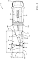
- Fig. 1 illustrates a non-limiting example of a trailer-detection system 10, hereafter referred to as the system 10.
- the system 10 is generally configured to detect objects proximate to a host-vehicle 12 equipped with the system 10.
- the system 10 is an improvement over prior radar-systems because the system 10 is configured to determine a presence (i.e. a trailer-presence) and size of a trailer 14 while the host-vehicle 12 is turning, and to adjust a sensing-boundary 16 that defines a blind-zone 18 of an operator 20 of the host-vehicle 12 based on a trailer-angle 22.
- This improvement enables the system 10 to continue to determine the presence and size of the trailer 14 when the trailer 14 is not directly behind the host-vehicle 12 and eliminate false warnings from an alert-device 24.
- the system 10 includes an angle-detector 26 used to determine the trailer-angle 22 relative to the host-vehicle 12 of the trailer 14 being towed by the host-vehicle 12.
- the trailer-angle 22 is defined as the angle between a host-vehicle-longitudinal-axis 28 and a trailer-longitudinal-axis 30, and is shown to be zero degrees (0°) in Fig. 1 (i.e. the trailer 14 is directly behind the host-vehicle 12).
- the angle-detector 26 is in electrical communication with a controller 32, and may be a device (not shown) mounted on a trailer-hitch 34 of the host-vehicle 12 or on the trailer 14, that is configured to provide a measure of the angle that exists between the host-vehicle-longitudinal-axis 28 and the trailer-longitudinal-axis 30.
- the angle-detector 26 may be a rear-facing camera (not shown), Lidar-sensor (not shown), or any other suitable method to detect the trailer-angle 22.
- the function of the angle-detector 26 may be provided by a yaw-sensor 36 that may already exist on most vehicles, such as the 6DF-1N6-C2-HWL from Honeywell Sensing and Control, Golden Valley, Minnesota, USA, and is used to determine a yaw-rate 37 of the host-vehicle 12, from which the trailer-angle 22 may be determined by the controller 32. It is advantageous to use the yaw-sensor 36 of the host-vehicle 12, in conjunction with a radar-sensor 38, to determine the trailer-angle 22 to eliminate a separate component of the system 10, reducing cost and complexity.
- the system 10 also includes the radar-sensor 38 used to detect an other-vehicle 40 present in the blind-zone 18 proximate to the host-vehicle 12.
- the radar-sensor 38 is configured to emit a radar-signal 41 toward a defined-area 42 proximate to the host-vehicle 12, and detect a reflected-signal 44 arising from the radar-signal 41 being reflected by detected-targets 46.
- Reflected-signals 44 from the weak-targets 46B may be, for example, a multi-path reflection from under the trailer 14 as the signal bounces between the trailer 14 and the ground, or by multi-path reflections traveling through a grated open-trailer or cross-frame members of the frame of the trailer 14.
- the radar-sensor 38 includes a left-sensor 38A and a right-sensor 38B.
- a radar sensor-system with a similarly configured radar-sensor 38 is available from Delphi Inc. of Troy, Michigan, USA and marketed as an Electronically Scanning Radar (ESR) or a Rear-Side-Detection-System (RSDS). It is contemplated that the teachings presented herein are applicable to radar-systems with one or more sensor devices.
- the radar-sensor 38 is generally configured to output a reflection-signal 48 that may include data indicative of a detected-target 46 present in the defined-area 42.
- Data that corresponds to the strong-targets 46A will generally be from consistent, non-intermittent signals. However, data that corresponds to the weak-targets 46B may be intermittent or have some substantial variability due to a low signal-to-noise ratio.
- the radar-sensor 38 may be configured to output a continuous or periodic data stream that includes a variety of signal characteristics associated with each target detected.
- the signal characteristics may include, but are not limited to a range 50 ( Fig. 2 ) to the detected-target 46 from the host-vehicle 12, a target-angle 52 to the detected-target 46 relative to the host-vehicle-longitudinal-axis 28, an amplitude (not shown) of the reflected-signal 44, and a relative-velocity 54 of closure relative to the detected-target 46.
- a target is generally detected because the reflected-signal 44 from the detected-target 46 has sufficient signal strength to meet some predetermined threshold. That is, there may be targets that reflect the radar-signal 41, but the strength of the reflected-signal 44 is insufficient to be characterized as one of the detected-targets 46.
- the system 10 may include the controller 32 configured to receive the reflection-signal 48 from the radar-sensor 38 and receive the trailer-angle 22 from the angle-detector 26.
- the controller 32 may include a processor (not shown) such as a microprocessor or other control circuitry such as analog and/or digital control circuitry including an application specific integrated circuit (ASIC) for processing data as should be evident to those in the art.
- the controller 32 may include memory, including non-volatile memory, such as electrically erasable programmable read-only memory (EEPROM) for storing one or more routines, thresholds and captured data. The one or more routines may be executed by the processor to perform steps for determining if signals received by the controller 32 indicate the presence of objects as described herein.
- the controller 32 may also be configured to receive vehicle related data such as yaw-rate 37, vehicle speed (not shown), and transmission gear (not shown).
- the controller 32 is generally configured to determine if the reflection-signal 48 arising from the detected-target 46 corresponds to (i.e. is associated with) the trailer 14 being towed by the host-vehicle 12. That is, the controller 32 determines if the trailer 14 is present, so is actually being towed by the host-vehicle 12.
- the controller 32 is also generally configured to define a trailer-boundary 56 characterized as occupied by the trailer 14 and thereby excluded from the defined-area 42 where objects can be detected in the blind-zone 18.
- the controller 32 can more readily determine if what seems to be a new target indicated by the reflected-signal 44 is likely from the trailer 14, or is likely from something other than the trailer 14, such as the other-vehicle 40.
- the controller 32 may also be configured to activate the alert-device 24 if the other-vehicle 40 is detected in the blind-zone 18.
- the blind-zone 18 preferably extends for a distance of four meters (4-meters) beyond the rear of the trailer 14 and may be calibrated to any distance desired.
- the blind-zone 18 preferably extends for a distance of 4-meters perpendicular to the left-side and right side of the host-vehicle 12 to sense objects in an adjoining roadway lane and may be calibrated to any distance desired.
- the boundaries of the defined-area 42 extend to the limits of the radar-signal 41 and are considered to be infinite for the purposes of this example.
- the trailer-boundary 56 and the blind-zone 18 are both subsets of the sensing-boundary 16.
- the reflection-signal 48 may be analyzed to categorize the data from each detected-target 46 with respect to a list of previously detected-targets 46 having established tracks.
- a track refers to one or more data sets that have been associated with a particular one of the detected-targets 46.
- the controller 32 determines if the data corresponds to a previously detected-target 46 or if a new-target has been detected. If the data corresponds to a previously detected-target 46, the data is added to or combined with prior data to update the track of the previously detected-target 46.
- the data may be characterized as a new-target and assigned a unique track identification number.
- the identification number may be assigned according to the order that data for a new detected-target 46 is received, or may be assigned an identification number according to a grid location in the defined-area 42.
- a detected-target 46 or a track that corresponds to (i.e. is associated with) the trailer 14 would have a relative-velocity 54 near zero, and that this condition would persist for an extended period of time. That is, the detected-target 46 corresponds to the trailer 14 if a range 50 to the detected-target 46 varies less than a variation threshold (e.g. less than 0.25 meters) for greater than a time threshold (e.g. greater than 5 seconds).
- a variation threshold e.g. less than 0.25 meters
- a time threshold e.g. greater than 5 seconds
- Fig. 3 illustrates the same system 10 from Fig. 1 when the host-vehicle 12 is turning while towing the trailer 14.
- the controller 32 is further configured to adjust the sensing-boundary 16 based on the trailer-angle 22.
- the controller 32 is further configured to adjust the trailer-boundary 56 based on the adjusted sensing-boundary 16 such that the detected-target 46, or a track that corresponds to the trailer 14, may continue to be tracked by the system 10 as described previously.
- the controller 32 is further configured to adjust the blind-zone 18 based on the adjusted trailer-boundary 56 to maintain the blind-zone 18 proximate to the trailer-boundary 56.
- the controller 32 is further configured to use the radar-sensor 38 to determine the relative-velocity 54 of the tracked-target associated with the trailer 14, and determine a trailer-angle 22 based on a longitudinal-velocity 58 and a lateral-velocity 60 ( Fig. 2 ) of the detected-target 46.
- the controller 32 is further configured to determine an axle-distance 72 that is defined as a distance between the trailer-hitch 34 and a trailer-axle 74 ( Fig. 2 ).
- the axle-distance 72 may be determined from the zero range-rate (ZRR) tracks of the detected-targets 46 that are associated with the trailer-axle 74 which may be detected as weak-targets 46B from multi-path reflections of the reflected-signal 44 from under the trailer 14 as the signal bounces between the trailer 14 and the ground.
- ZRR zero range-rate
- An additional benefit to adjusting the trailer-boundary 56 based on the trailer-angle 22 may be realized in other autonomous-vehicle or semi-autonomous-vehicle applications where the controller 32 may be configured to determine whether a current path of the host-vehicle 12 and trailer 14 may collide with an object or other-vehicle 40, based on the turning path of the combination of the host-vehicle 12 and the trailer 14. In such a situation, the controller 32 may also be configured to activate the alert-device 24 to warn the operator 20 of the impending collision.
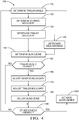
- Fig. 4 illustrates a non-limiting method 100 that is an overview of a process carried out by the controller 32 to determine the trailer-angle 22 and adjust the sensing-boundary 16 based on the trailer-angle 22.
- Step 110 DETERMINE TRAILER-ANGLE, may include the controller 32 receiving an indication of the trailer-angle 22 from an angle-detector 26 used to determine the trailer-angle 22 relative to the host-vehicle 12 of the trailer 14 being towed by the host-vehicle 12.
- the trailer-angle 22 is defined as the angle between a host-vehicle-longitudinal-axis 28 and a trailer-longitudinal-axis 30, and is shown to be zero degrees (0°) in Fig. 1 (i.e. the trailer 14 is directly behind the host-vehicle 12).
- the angle-detector 26 is in electrical communication with a controller 32, and may be a device (not shown) mounted on the trailer-hitch 34 of the host-vehicle 12 or on the trailer 14, that is configured to provide a measure of the angle that exists between the host-vehicle-longitudinal-axis 28 and the trailer-longitudinal-axis 30.
- the angle-detector 26 is a yaw-sensor 36 that may exist on most vehicles, such as the 6DF-1N6-C2-HWL from Honeywell Sensing and Control, Golden Valley, Minnesota, USA, and is used to determine the yaw-rate 37 of the host-vehicle 12, from which the trailer-angle 22 may be determined by the controller 32.
- the controller 32 may determine the trailer-angle 22 by using the radar-sensor 38 to determine the relative-velocity 54 of the tracked-target associated with the trailer 14, and determine the trailer-angle 22 based on a longitudinal-velocity 58 and a lateral-velocity 60 ( Fig. 2 ) of the detected-target 46.
- Step 120 DETERMINE SENSING-BOUNDARY, may include the controller 32 receiving a signal from the radar-sensor 38 configured to emit a radar-signal 41 toward a defined-area 42 proximate to the host-vehicle 12, and detect a reflected-signal 44 arising from the radar-signal 41 being reflected by detected-targets 46.
- the controller 32 receiving a signal from the radar-sensor 38 configured to emit a radar-signal 41 toward a defined-area 42 proximate to the host-vehicle 12, and detect a reflected-signal 44 arising from the radar-signal 41 being reflected by detected-targets 46.
- strong-targets 46A such as the front of the trailer 14 or other highly reflective objects such as wheel wells or fenders of the trailer 14
- weak-targets 46B such as the back bumper of the trailer 14 or smaller examples of the other-vehicle 40 such as a motorcycle for example.
- Reflected signals from the weak-targets 46B may be, for example, a multi-path reflection from under the trailer 14 as the signal bounces between the trailer 14 and the ground, or by multi-path reflections traveling through a grated open-trailer or cross-frame members of the frame of the trailer 14.
- the sensing-boundary 16 extends for a distance of 4-meters beyond the rear of the trailer 14, and extends for a distance of 4-meters perpendicular to the left-side and right side of the host-vehicle 12.
- Step 130 DETERMINE TRAILER-BOUNDARY, may include using the zero range-rate (ZRR) tracks to determine a length 62 of the trailer 14 and a width 64 of the trailer 14 ( Fig. 2 ). Given the track data, each track is compared to a defined bounded area behind the host-vehicle 12 and only tracks that are within those bounds are used. The boundary is set by calibrations and the current boundary is 2.4 meters wide and 16.2 meters long. Additional constraints such as minimum amplitudes or detections sources may be applied to qualify a track prior to using it to determine the length 62 and width 64.
- ZRR zero range-rate
- the length 62 and width 64 is determined in two steps: Determine the unfiltered (raw) value, and Filter the raw value to the final value.
- the unfiltered length 62 is determined by taking the maximum longitudinal-distance back from the host-vehicle's 12 rear bumper and the raw width 64 is determined by taking the maximum lateral-distance between any two points within the bounded area.
- the unfiltered measures are then filtered.
- One way of filtering is to use a low pass filter with a long time constant such as five seconds.
- the second way of filtering is to create a histogram of the unfiltered measures where one count is added to the bin that corresponds to the current unfiltered measure and then the bin with the highest counts is selected as the filtered measure.
- the length 62 of the trailer-boundary 56 can be determined based on a longitudinal distance to a most-distant-target 66 that corresponds to the trailer 14 and is closer to the host-vehicle 12 than a maximum trailer-length (16.2 meters).
- the width 64 of the trailer-boundary 56 can be determined based on a lateral distance between a left-most-target 68 that corresponds to the trailer 14, and a right-most-target 70 that corresponds to the trailer 14.
- Step 132, DETERMINE AXLE-DISTANCE may include determining an axle-distance 72 that is defined as a distance between the trailer-hitch 34 and a trailer-axle 74 ( Fig. 2 ).
- the axle-distance 72 may be determined from the ZRR tracks of the detected-targets 46 that are associated with the trailer-axle 74 which may be detected as weak-targets 46B from multi-path reflections of the reflected-signal 44 from under the trailer 14 as the signal bounces between the trailer 14 and the ground.
- Step 140 DETERMINE BLIND-ZONE, may include determining a blind-zone 18 proximate to the host-vehicle 12 that may extend a distance of 4-meters beyond the rear of the trailer 14 towed by the host-vehicle 12 and may extend a distance of 4-meters perpendicular to the left-side and right-side of the host-vehicle 12.
- Step 150 directs a logic path of the method 100 based on the outcome of the determination of whether or not the trailer-angle 22 has changed more than a predetermined threshold.
- the threshold may be set to 5° for normal driving conditions, above which the trailer-angle 22 is considered by the controller 32 to have changed.
- the threshold may be varied based on the speed and direction of the host-vehicle 12. For example, the threshold may be increased at higher speeds to accommodate for trailer-sway, or decreased at lower speeds to improve the sensitivity of the system 10 when performing a backing maneuver of the trailer 14.
- Step 160 ADJUST SENSING-BOUNDARY, may include the step of adjusting the sensing-boundary 16 such that it remains generally centered along the trailer-longitudinal-axis 30. This adjustment generally matches the change in the trailer-angle 22 as determined by the angle-detector 26.
- Step 170 may include the step of adjusting the trailer-boundary 56 and may include using the ZRR tracks to determine a length 62 of the trailer 14 and a width 64 of the trailer 14 as described previously.
- Step 180 may include adjusting the blind-zone 18 to remain proximate to the sides of the trailer 14. This adjustment generally matches the change in the trailer-angle 22 as determined by the angle-detector 26.
- Step 190, OTHER-VEHICLE PRESENT? directs a logic path of the method 100 based on the outcome of the determination of whether or not the other-vehicle 40 is present in the blind-zone 18.
- the controller 32 is generally configured to determine if the reflection-signal 48 arising from the detected-target 46 corresponds to (i.e. is associated with) the trailer 14 being towed by the host-vehicle 12.
- the controller 32 is also generally configured to define the trailer-boundary 56 characterized as occupied by the trailer 14 and thereby excluded from the defined-area 42 where objects can be detected in the blind-zone 18.
- the controller 32 can more readily determine if what seems to be a new target indicated by the reflected-signal 44 is likely from the trailer 14, or is likely from something other than the trailer 14, such as the other-vehicle 40.
- Step 200 may include activating the alert-device 24 to warn the operator 20 that the other-vehicle 40 has entered the blind-zone 18.
- the alert-device 24 may be an audible warning, a visual warning, and a vibrational warning.
- a trailer-detection system 10 (the system 10), a controller 32 for the system 10 and a method 100 of operating the system 10 is provided.
- the teachings presented herein advantageously improve the performance of the system 10 by detecting that the host-vehicle 12 is towing a trailer 14 while the host-vehicle 12 is turning, and determining the size of the trailer 14 so that the radar-system can more readily discriminate detected-targets 46 that correspond to (i.e. are associated with) the trailer 14 from detected-targets 46 that do not correspond to the trailer 14.
Landscapes
- Engineering & Computer Science (AREA)
- Radar, Positioning & Navigation (AREA)
- Remote Sensing (AREA)
- Physics & Mathematics (AREA)
- General Physics & Mathematics (AREA)
- Computer Networks & Wireless Communication (AREA)
- Electromagnetism (AREA)
- Automation & Control Theory (AREA)
- Mathematical Physics (AREA)
- Transportation (AREA)
- Mechanical Engineering (AREA)
- Radar Systems Or Details Thereof (AREA)
- Traffic Control Systems (AREA)
Abstract
A trailer-detection system (10) includes a radar-sensor (38), an angle-detector (26), and a controller (32). The radar-sensor (38) is used to detect an other-vehicle (40) present in a blind-zone (18) proximate to the host-vehicle (12). The angle-detector (26) is used to determine a trailer-angle (22) relative to a host-vehicle (12) of a trailer (14) being towed by the host-vehicle (12). The controller (32) is in communication with the angle-detector (26) and the radar-sensor (38). The controller (32) is configured to determine a trailer-presence of the trailer (14) based on the radar-signal (41) and the trailer-angle (22).
Description
- This disclosure generally relates to a vehicle radar-system, and more particularly relates to a system that determines if a detected target corresponds to a trailer towed by the vehicle, and defines a trailer zone that is occupied by the trailer and thereby excluded from a defined area where objects can be detected.
- It is known to equip a host-vehicle with a radar-system for detecting objects such as other-vehicles proximate to the host-vehicle. Such object detection is desirable for detecting, for example, other-vehicles in the so called blind-spot which is not readily observable by an operator of a host-vehicle using typical side-view and rear-view mirrors, and for detecting a trailer towed by the host-vehicle. Such object detection may also be useful to warn the operator of a rapidly approaching vehicle in an adjacent lane if the operator indicates that a lane-change is about to be executed by, for example, activating a turn-signal indicator, or for detecting objects behind the host-vehicle when backing-up. If the host-vehicle is towing a trailer, reflections of radar-signals by the trailer may interfere with the detection of a target that does not correspond to or is not associated with the trailer. In addition, when the host-vehicle is turning, the trailer may cause the warning-system to activate and give a false indication of another object or vehicle proximate to the host-vehicle, as the trailer detection zone only applies to the area directly behind the host-vehicle.
- In accordance with one embodiment, a trailer-detection system configured to detect objects proximate to a vehicle is provided. The system includes an angle-detector, a radar-sensor, and a controller. The angle-detector is used to determine a trailer-angle relative to a host-vehicle of a trailer being towed by the host-vehicle. The radar-sensor is used to detect an other-vehicle present in a blind-zone proximate to the host-vehicle. The controller is in communication with the angle-detector and the radar-sensor. The controller is configured to determine a trailer-presence of the trailer based on the radar-signal and the trailer-angle.
- Further features and advantages will appear more clearly on a reading of the following detailed description of the preferred embodiment, which is given by way of non-limiting example only and with reference to the accompanying drawings.
- The controller may be further configured to determine a trailer-presence when the trailer is not directly behind the host-vehicle. The trailer-angle of zero degrees may be defined as a trailer-longitudinal-axis being parallel to a host-vehicle-longitudinal-axis, and the trailer-presence is determined when the trailer-angle is greater than five degrees. The system may include an alert-device detectable by an operator of the host-vehicle, and the controller may be further configured to activate the alert-device when the object detected is not the trailer. The angle-detector may include a yaw-sensor used to determine a yaw-rate of the host-vehicle, and the trailer-angle may be determined based on the yaw-rate. The controller may be further configured to use the radar-sensor to determine a relative-velocity of a tracked-target associated with the trailer, wherein an expected-location of the tracked-target is determined based on the trailer-angle. The controller may determine a trailer-boundary based on the radar-signal. The controller may determine a length of the trailer based on the radar-signal. The controller may determine a width of the trailer based on the radar-signal. The controller may determine an axle-distance from a trailer-hitch to a trailer-axle based on the radar-signal.
- In accordance with the invention, a method to detect a trailer towed by a host-vehicle comprises the steps of:
- receiving a radar-signal from a radar-sensor, said radar-signal indicative of an object proximate to the host-vehicle;
- receiving an indication of a trailer-angle of a trailer towed by the host-vehicle from an angle-detector; and
- determining a trailer-presence of the trailer based on the radar-signal and the trailer-angle
- The step of determining the trailer-presence may be performed when the trailer is not directly behind the host-vehicle. The trailer-angle of zero degrees may be defined as a trailer-longitudinal-axis being parallel to a host-vehicle-longitudinal-axis , and the trailer-presence may be determined when the trailer-angle is greater than five degrees. The method may further comprise the step of determining a yaw-rate of the host-vehicle using a yaw-sensor, and the trailer-angle may be determined based on the yaw-rate. The method may further comprise the step of determining a relative-velocity of a tracked-target associated with the trailer using the radar-sensor, and the trailer-angle based on the relative-velocity. The method may further comprise the step of determining a trailer-boundary based on the radar-signal. Determining the trailer-boundary may include determining a length of the trailer based on the radar-signal. Determining the trailer-boundary may include determining a width of the trailer based on the radar-signal. The method may further comprise the step of determining a distance from a trailer-hitch to a trailer-axle based on the radar-signal.
- The present invention will now be described, by way of example with reference to the accompanying drawings, in which:
-
Fig. 1 is a top view of a host-vehicle equipped with a trailer-detection system and towing a trailer in accordance with one embodiment; -
Fig. 2 is a close-up ofFig. 1 in accordance with one embodiment; -
Fig. 3 is a top view of a host-vehicle equipped with a trailer-detection system and towing a trailer in accordance with one embodiment; and -
Fig. 4 is a flowchart of a method executed by the system ofFig. 3 in accordance with one embodiment. - Described herein is an improvement to vehicle radar-systems that are used to detect objects such as other-vehicles that are close to or approaching a host-vehicle on which the radar-system is installed. The improvement is related to detecting that the host-vehicle is towing a trailer while the host-vehicle is turning, and determining the size of the trailer so that the radar system can more readily discriminate detected targets that correspond to (i.e. are associated with) the trailer from detected targets that do not correspond to the trailer. This improvement is beneficial because the blind spot detection system will not alert the operator of the host-vehicle when the trailer towed by the host-vehicle is present in a blind-zone of the operator. The trailer size information may also be used to, for example, adjust expected vehicle dynamic characteristics, and thereby compensate for the extra load presented by the trailer. Other benefits include improvements to active safety features of a vehicle when towing the trailer, and to improve the controls of an autonomous vehicle that is towing the trailer.
-
Fig. 1 illustrates a non-limiting example of a trailer-detection system 10, hereafter referred to as thesystem 10. Thesystem 10 is generally configured to detect objects proximate to a host-vehicle 12 equipped with thesystem 10. As will be described in more detail below, thesystem 10 is an improvement over prior radar-systems because thesystem 10 is configured to determine a presence (i.e. a trailer-presence) and size of atrailer 14 while the host-vehicle 12 is turning, and to adjust a sensing-boundary 16 that defines a blind-zone 18 of anoperator 20 of the host-vehicle 12 based on a trailer-angle 22. This improvement enables thesystem 10 to continue to determine the presence and size of thetrailer 14 when thetrailer 14 is not directly behind the host-vehicle 12 and eliminate false warnings from an alert-device 24. - The
system 10 includes an angle-detector 26 used to determine the trailer-angle 22 relative to the host-vehicle 12 of thetrailer 14 being towed by the host-vehicle 12. The trailer-angle 22 is defined as the angle between a host-vehicle-longitudinal-axis 28 and a trailer-longitudinal-axis 30, and is shown to be zero degrees (0°) inFig. 1 (i.e. thetrailer 14 is directly behind the host-vehicle 12). The angle-detector 26 is in electrical communication with acontroller 32, and may be a device (not shown) mounted on a trailer-hitch 34 of the host-vehicle 12 or on thetrailer 14, that is configured to provide a measure of the angle that exists between the host-vehicle-longitudinal-axis 28 and the trailer-longitudinal-axis 30. The angle-detector 26 may be a rear-facing camera (not shown), Lidar-sensor (not shown), or any other suitable method to detect the trailer-angle 22. Preferably, the function of the angle-detector 26 may be provided by a yaw-sensor 36 that may already exist on most vehicles, such as the 6DF-1N6-C2-HWL from Honeywell Sensing and Control, Golden Valley, Minnesota, USA, and is used to determine a yaw-rate 37 of the host-vehicle 12, from which the trailer-angle 22 may be determined by thecontroller 32. It is advantageous to use the yaw-sensor 36 of the host-vehicle 12, in conjunction with a radar-sensor 38, to determine the trailer-angle 22 to eliminate a separate component of thesystem 10, reducing cost and complexity. - The
system 10 also includes the radar-sensor 38 used to detect an other-vehicle 40 present in the blind-zone 18 proximate to the host-vehicle 12. The radar-sensor 38 is configured to emit a radar-signal 41 toward a defined-area 42 proximate to the host-vehicle 12, and detect a reflected-signal 44 arising from the radar-signal 41 being reflected by detected-targets 46. When thetrailer 14 is being towed, there will generally be some consistent reflected signals created from strong-targets 46A such as the front of thetrailer 14 or other highly reflective objects such as wheel wells or fenders of thetrailer 14; and some intermittent reflected signals from weak-targets 46B such as the back bumper of thetrailer 14 or smaller examples of the other-vehicle 40 such as a motorcycle for example. Reflected-signals 44 from the weak-targets 46B may be, for example, a multi-path reflection from under thetrailer 14 as the signal bounces between thetrailer 14 and the ground, or by multi-path reflections traveling through a grated open-trailer or cross-frame members of the frame of thetrailer 14. - In the non-limiting example illustrated in
Fig. 1 , the radar-sensor 38 includes a left-sensor 38A and a right-sensor 38B. A radar sensor-system with a similarly configured radar-sensor 38 is available from Delphi Inc. of Troy, Michigan, USA and marketed as an Electronically Scanning Radar (ESR) or a Rear-Side-Detection-System (RSDS). It is contemplated that the teachings presented herein are applicable to radar-systems with one or more sensor devices. - The radar-
sensor 38 is generally configured to output a reflection-signal 48 that may include data indicative of a detected-target 46 present in the defined-area 42. Data that corresponds to the strong-targets 46A will generally be from consistent, non-intermittent signals. However, data that corresponds to the weak-targets 46B may be intermittent or have some substantial variability due to a low signal-to-noise ratio. - By way of example and not limitation, the radar-
sensor 38 may be configured to output a continuous or periodic data stream that includes a variety of signal characteristics associated with each target detected. The signal characteristics may include, but are not limited to a range 50 (Fig. 2 ) to the detected-target 46 from the host-vehicle 12, a target-angle 52 to the detected-target 46 relative to the host-vehicle-longitudinal-axis 28, an amplitude (not shown) of the reflected-signal 44, and a relative-velocity 54 of closure relative to the detected-target 46. A target is generally detected because the reflected-signal 44 from the detected-target 46 has sufficient signal strength to meet some predetermined threshold. That is, there may be targets that reflect the radar-signal 41, but the strength of the reflected-signal 44 is insufficient to be characterized as one of the detected-targets 46. - The
system 10 may include thecontroller 32 configured to receive the reflection-signal 48 from the radar-sensor 38 and receive the trailer-angle 22 from the angle-detector 26. Thecontroller 32 may include a processor (not shown) such as a microprocessor or other control circuitry such as analog and/or digital control circuitry including an application specific integrated circuit (ASIC) for processing data as should be evident to those in the art. Thecontroller 32 may include memory, including non-volatile memory, such as electrically erasable programmable read-only memory (EEPROM) for storing one or more routines, thresholds and captured data. The one or more routines may be executed by the processor to perform steps for determining if signals received by thecontroller 32 indicate the presence of objects as described herein. Thecontroller 32 may also be configured to receive vehicle related data such as yaw-rate 37, vehicle speed (not shown), and transmission gear (not shown). - The
controller 32 is generally configured to determine if the reflection-signal 48 arising from the detected-target 46 corresponds to (i.e. is associated with) thetrailer 14 being towed by the host-vehicle 12. That is, thecontroller 32 determines if thetrailer 14 is present, so is actually being towed by the host-vehicle 12. Thecontroller 32 is also generally configured to define a trailer-boundary 56 characterized as occupied by thetrailer 14 and thereby excluded from the defined-area 42 where objects can be detected in the blind-zone 18. By defining the portion of the defined-area 42 that is the trailer-boundary 56, thecontroller 32 can more readily determine if what seems to be a new target indicated by the reflected-signal 44 is likely from thetrailer 14, or is likely from something other than thetrailer 14, such as the other-vehicle 40. Thecontroller 32 may also be configured to activate the alert-device 24 if the other-vehicle 40 is detected in the blind-zone 18. The blind-zone 18 preferably extends for a distance of four meters (4-meters) beyond the rear of thetrailer 14 and may be calibrated to any distance desired. The blind-zone 18 preferably extends for a distance of 4-meters perpendicular to the left-side and right side of the host-vehicle 12 to sense objects in an adjoining roadway lane and may be calibrated to any distance desired. The boundaries of the defined-area 42 extend to the limits of the radar-signal 41 and are considered to be infinite for the purposes of this example. As used herein, the trailer-boundary 56 and the blind-zone 18 are both subsets of the sensing-boundary 16. - The reflection-
signal 48 may be analyzed to categorize the data from each detected-target 46 with respect to a list of previously detected-targets 46 having established tracks. As used herein, a track refers to one or more data sets that have been associated with a particular one of the detected-targets 46. By way of example and not limitation, if the amplitude of the reflected-signal 44 indicated in the reflection-signal 48 is above a predetermined amplitude threshold, then thecontroller 32 determines if the data corresponds to a previously detected-target 46 or if a new-target has been detected. If the data corresponds to a previously detected-target 46, the data is added to or combined with prior data to update the track of the previously detected-target 46. If the data does not correspond to any previously detected-target 46 because, for example, it is located too far away from any previously detected-target 46, then it may be characterized as a new-target and assigned a unique track identification number. The identification number may be assigned according to the order that data for a new detected-target 46 is received, or may be assigned an identification number according to a grid location in the defined-area 42. - The expectation is that a detected-
target 46 or a track that corresponds to (i.e. is associated with) thetrailer 14 would have a relative-velocity 54 near zero, and that this condition would persist for an extended period of time. That is, the detected-target 46 corresponds to thetrailer 14 if arange 50 to the detected-target 46 varies less than a variation threshold (e.g. less than 0.25 meters) for greater than a time threshold (e.g. greater than 5 seconds). It is noted that characterizing a target as having a relative-velocity 54 near zero and having a variation inrange 50 less than a variation threshold are effectively the same characterization. As such, references to the term 'range-rate' in the discussion that follows are directly comparable to the terms 'relative-velocity', 'relative-rate' and 'variation-in-range'. -
Fig. 3 illustrates thesame system 10 fromFig. 1 when the host-vehicle 12 is turning while towing thetrailer 14. In this non-limiting example thecontroller 32 is further configured to adjust the sensing-boundary 16 based on the trailer-angle 22. Thecontroller 32 is further configured to adjust the trailer-boundary 56 based on the adjusted sensing-boundary 16 such that the detected-target 46, or a track that corresponds to thetrailer 14, may continue to be tracked by thesystem 10 as described previously. Thecontroller 32 is further configured to adjust the blind-zone 18 based on the adjusted trailer-boundary 56 to maintain the blind-zone 18 proximate to the trailer-boundary 56. If these adjustments are not made, the previously detected-targets 46 in the trailer-boundary 56 would be considered by thesystem 10 as being in the blind-zone 18 (due to the yaw of the host-vehicle 12), likely resulting in a false detection of new-targets and cause the alert-device 24 to be activated. Thecontroller 32 is further configured to use the radar-sensor 38 to determine the relative-velocity 54 of the tracked-target associated with thetrailer 14, and determine a trailer-angle 22 based on a longitudinal-velocity 58 and a lateral-velocity 60 (Fig. 2 ) of the detected-target 46. - The
controller 32 is further configured to determine an axle-distance 72 that is defined as a distance between the trailer-hitch 34 and a trailer-axle 74 (Fig. 2 ). The axle-distance 72 may be determined from the zero range-rate (ZRR) tracks of the detected-targets 46 that are associated with the trailer-axle 74 which may be detected as weak-targets 46B from multi-path reflections of the reflected-signal 44 from under thetrailer 14 as the signal bounces between thetrailer 14 and the ground. - An additional benefit to adjusting the trailer-
boundary 56 based on the trailer-angle 22 may be realized in other autonomous-vehicle or semi-autonomous-vehicle applications where thecontroller 32 may be configured to determine whether a current path of the host-vehicle 12 andtrailer 14 may collide with an object or other-vehicle 40, based on the turning path of the combination of the host-vehicle 12 and thetrailer 14. In such a situation, thecontroller 32 may also be configured to activate the alert-device 24 to warn theoperator 20 of the impending collision. -
Fig. 4 illustrates anon-limiting method 100 that is an overview of a process carried out by thecontroller 32 to determine the trailer-angle 22 and adjust the sensing-boundary 16 based on the trailer-angle 22. -
Step 110, DETERMINE TRAILER-ANGLE, may include thecontroller 32 receiving an indication of the trailer-angle 22 from an angle-detector 26 used to determine the trailer-angle 22 relative to the host-vehicle 12 of thetrailer 14 being towed by the host-vehicle 12. The trailer-angle 22 is defined as the angle between a host-vehicle-longitudinal-axis 28 and a trailer-longitudinal-axis 30, and is shown to be zero degrees (0°) inFig. 1 (i.e. thetrailer 14 is directly behind the host-vehicle 12). The angle-detector 26 is in electrical communication with acontroller 32, and may be a device (not shown) mounted on the trailer-hitch 34 of the host-vehicle 12 or on thetrailer 14, that is configured to provide a measure of the angle that exists between the host-vehicle-longitudinal-axis 28 and the trailer-longitudinal-axis 30. Preferably the angle-detector 26 is a yaw-sensor 36 that may exist on most vehicles, such as the 6DF-1N6-C2-HWL from Honeywell Sensing and Control, Golden Valley, Minnesota, USA, and is used to determine the yaw-rate 37 of the host-vehicle 12, from which the trailer-angle 22 may be determined by thecontroller 32. It is advantageous to use the yaw-sensor 36 of the host-vehicle 12, in conjunction with a radar-sensor 38, to determine the trailer-angle 22 to eliminate a separate component of thesystem 10, reducing cost and complexity. Preferably thecontroller 32 may determine the trailer-angle 22 by using the radar-sensor 38 to determine the relative-velocity 54 of the tracked-target associated with thetrailer 14, and determine the trailer-angle 22 based on a longitudinal-velocity 58 and a lateral-velocity 60 (Fig. 2 ) of the detected-target 46. -
Step 120, DETERMINE SENSING-BOUNDARY, may include thecontroller 32 receiving a signal from the radar-sensor 38 configured to emit a radar-signal 41 toward a defined-area 42 proximate to the host-vehicle 12, and detect a reflected-signal 44 arising from the radar-signal 41 being reflected by detected-targets 46. When thetrailer 14 is being towed, there will generally be some consistent reflected signals created from strong-targets 46A such as the front of thetrailer 14 or other highly reflective objects such as wheel wells or fenders of thetrailer 14; and some intermittent reflected signals from weak-targets 46B such as the back bumper of thetrailer 14 or smaller examples of the other-vehicle 40 such as a motorcycle for example. Reflected signals from the weak-targets 46B may be, for example, a multi-path reflection from under thetrailer 14 as the signal bounces between thetrailer 14 and the ground, or by multi-path reflections traveling through a grated open-trailer or cross-frame members of the frame of thetrailer 14. Preferably, the sensing-boundary 16 extends for a distance of 4-meters beyond the rear of thetrailer 14, and extends for a distance of 4-meters perpendicular to the left-side and right side of the host-vehicle 12. -
Step 130, DETERMINE TRAILER-BOUNDARY, may include using the zero range-rate (ZRR) tracks to determine alength 62 of thetrailer 14 and awidth 64 of the trailer 14 (Fig. 2 ). Given the track data, each track is compared to a defined bounded area behind the host-vehicle 12 and only tracks that are within those bounds are used. The boundary is set by calibrations and the current boundary is 2.4 meters wide and 16.2 meters long. Additional constraints such as minimum amplitudes or detections sources may be applied to qualify a track prior to using it to determine thelength 62 andwidth 64. After the final track set is determined, thelength 62 andwidth 64 is determined in two steps: Determine the unfiltered (raw) value, and Filter the raw value to the final value. Theunfiltered length 62 is determined by taking the maximum longitudinal-distance back from the host-vehicle's 12 rear bumper and theraw width 64 is determined by taking the maximum lateral-distance between any two points within the bounded area. The unfiltered measures are then filtered. One way of filtering is to use a low pass filter with a long time constant such as five seconds. The second way of filtering is to create a histogram of the unfiltered measures where one count is added to the bin that corresponds to the current unfiltered measure and then the bin with the highest counts is selected as the filtered measure. The histogram filter approach appears to create a more stable estimation than the low pass filtered measure. By executing the processes described above, thelength 62 of the trailer-boundary 56 can be determined based on a longitudinal distance to a most-distant-target 66 that corresponds to thetrailer 14 and is closer to the host-vehicle 12 than a maximum trailer-length (16.2 meters). Similarly, thewidth 64 of the trailer-boundary 56 can be determined based on a lateral distance between a left-most-target 68 that corresponds to thetrailer 14, and a right-most-target 70 that corresponds to thetrailer 14. -
Step 132, DETERMINE AXLE-DISTANCE, may include determining an axle-distance 72 that is defined as a distance between the trailer-hitch 34 and a trailer-axle 74 (Fig. 2 ). The axle-distance 72 may be determined from the ZRR tracks of the detected-targets 46 that are associated with the trailer-axle 74 which may be detected as weak-targets 46B from multi-path reflections of the reflected-signal 44 from under thetrailer 14 as the signal bounces between thetrailer 14 and the ground. -
Step 140, DETERMINE BLIND-ZONE, may include determining a blind-zone 18 proximate to the host-vehicle 12 that may extend a distance of 4-meters beyond the rear of thetrailer 14 towed by the host-vehicle 12 and may extend a distance of 4-meters perpendicular to the left-side and right-side of the host-vehicle 12. -
Step 150, TRAILER ANGLE CHANGE?, directs a logic path of themethod 100 based on the outcome of the determination of whether or not the trailer-angle 22 has changed more than a predetermined threshold. The threshold may be set to 5° for normal driving conditions, above which the trailer-angle 22 is considered by thecontroller 32 to have changed. The threshold may be varied based on the speed and direction of the host-vehicle 12. For example, the threshold may be increased at higher speeds to accommodate for trailer-sway, or decreased at lower speeds to improve the sensitivity of thesystem 10 when performing a backing maneuver of thetrailer 14. -
Step 160, ADJUST SENSING-BOUNDARY, may include the step of adjusting the sensing-boundary 16 such that it remains generally centered along the trailer-longitudinal-axis 30. This adjustment generally matches the change in the trailer-angle 22 as determined by the angle-detector 26. -
Step 170, ADJUST TRAILER-BOUNDARY, may include the step of adjusting the trailer-boundary 56 and may include using the ZRR tracks to determine alength 62 of thetrailer 14 and awidth 64 of thetrailer 14 as described previously. -
Step 180, ADJUST BLIND-ZONE, may include adjusting the blind-zone 18 to remain proximate to the sides of thetrailer 14. This adjustment generally matches the change in the trailer-angle 22 as determined by the angle-detector 26. -
Step 190, OTHER-VEHICLE PRESENT?, directs a logic path of themethod 100 based on the outcome of the determination of whether or not the other-vehicle 40 is present in the blind-zone 18. Thecontroller 32 is generally configured to determine if the reflection-signal 48 arising from the detected-target 46 corresponds to (i.e. is associated with) thetrailer 14 being towed by the host-vehicle 12. Thecontroller 32 is also generally configured to define the trailer-boundary 56 characterized as occupied by thetrailer 14 and thereby excluded from the defined-area 42 where objects can be detected in the blind-zone 18. By defining the portion of the defined-area 42 that is the trailer-boundary 56, thecontroller 32 can more readily determine if what seems to be a new target indicated by the reflected-signal 44 is likely from thetrailer 14, or is likely from something other than thetrailer 14, such as the other-vehicle 40. -
Step 200, ACTIVATE ALERT-DEVICE, may include activating the alert-device 24 to warn theoperator 20 that the other-vehicle 40 has entered the blind-zone 18. The alert-device 24 may be an audible warning, a visual warning, and a vibrational warning. - Accordingly, a trailer-detection system 10 (the system 10), a
controller 32 for thesystem 10 and amethod 100 of operating thesystem 10 is provided. The teachings presented herein advantageously improve the performance of thesystem 10 by detecting that the host-vehicle 12 is towing atrailer 14 while the host-vehicle 12 is turning, and determining the size of thetrailer 14 so that the radar-system can more readily discriminate detected-targets 46 that correspond to (i.e. are associated with) thetrailer 14 from detected-targets 46 that do not correspond to thetrailer 14. - While this invention has been described in terms of the preferred embodiments thereof, it is not intended to be so limited, but rather only to the extent set forth in the claims that follow.
Claims (15)
- A trailer-detection system (10) configured to detect a trailer (14) towed by a host-vehicle (12), said system (10) comprising:a radar-sensor (38) used to detect a radar-signal (41) indicative of an object proximate to the host-vehicle (12);an angle-detector (26) used to determine a trailer-angle (22) relative to the host-vehicle (12) of a trailer (14) towed by the host-vehicle (12); anda controller (32) in communication with the angle-detector (26) and the radar-sensor (38), said controller (32) configured to determine a trailer-presence of the trailer (14) based on the radar-signal (41) and the trailer-angle (22).
- The system (10) in accordance with claim 1, wherein the trailer-angle (22) of zero degrees is defined as a trailer-longitudinal-axis (30) being parallel to a host-vehicle-longitudinal-axis (28), and the trailer-presence is determined when the trailer-angle (22) is greater than five degrees.
- The system (10) according to any one of the preceding claims, wherein the system (10) includes an alert-device (24) detectable by an operator (20) of the host-vehicle (12), and the controller (32) is further configured to activate the alert-device (24) when the object detected is not the trailer (14).
- The system (10) according to any one of the preceding claims, wherein the angle-detector (26) includes a yaw-sensor (36) used to determine a yaw-rate (37) of the host-vehicle (12), and the trailer-angle (22) is determined based on the yaw-rate (37).
- The system (10) according to any one of the preceding claims, wherein the controller (32) is further configured to use the radar-sensor (38) to determine a relative-velocity (54) of a tracked-target associated with the trailer (14), wherein an expected-location of the tracked-target is determined based on the trailer-angle (22).
- The system (10) according to any one of the preceding claims, wherein the controller (32) determines a trailer-boundary (56) based on the radar-signal (41).
- The system (10) according to any one of the preceding claims, wherein the controller (32) determines an axle-distance (72) from a trailer-hitch (34) to a trailer-axle (74) based on the radar-signal (41).
- A method (100) to detect a trailer (14) towed by a host-vehicle (12), said method (100) comprising:receiving (120) a radar-signal (41) from a radar-sensor (38), said radar-signal (41) indicative of an object proximate to the host-vehicle (12);receiving (110) an indication of a trailer-angle (22) of a trailer (14) towed by the host-vehicle (12) from an angle-detector (26); anddetermining (110) a trailer-presence of the trailer (14) based on the radar-signal (41) and the trailer-angle (22).
- The method (100) in accordance with claim 8, wherein the step of determining (150) the trailer-presence is performed when the trailer (14) is not directly behind the host-vehicle (12).
- The method (100) according to any one of the claims 8 to 9, wherein the trailer-angle (22) of zero degrees is defined as a trailer-longitudinal-axis (30) being parallel to a host-vehicle-longitudinal-axis (28), and the trailer-presence is determined (150) when the trailer-angle (22) is greater than five degrees.
- The method (100) according to any one the claims 8 to 10, wherein the method (100) includes activating (200) an alert-device (24) detectable by an operator (20) of the host-vehicle (12) when the object detected is not the trailer (14).
- The method (100) according to any one of the claims 8 to 11, wherein the method (100) includes determining (110) a yaw-rate (37) of the host-vehicle (12) using a yaw-sensor (36), and the trailer-angle (22) is determined (110) based on the yaw-rate (37).
- The method (100) according to any one of the claims 8 to 12, wherein the method (100) includes determining (110) a relative-velocity (54) of a tracked-target associated with the trailer (14) using the radar-sensor (38), and the trailer-angle (22) based on the relative-velocity (54).
- The method (100) according to any one of the claims 8 to 13, wherein the method (100) includes determining (130) a trailer-boundary (56) based on the radar-signal (41).
- The method (100) according to claim 14, wherein determining (130) the trailer-boundary (56) includes determining (130) a length (62) of the trailer (14) based on the radar-signal (41).
Applications Claiming Priority (1)
| Application Number | Priority Date | Filing Date | Title |
|---|---|---|---|
| US15/186,602 US10351146B2 (en) | 2016-06-20 | 2016-06-20 | Trailer estimation improvement |
Publications (1)
| Publication Number | Publication Date |
|---|---|
| EP3260879A1 true EP3260879A1 (en) | 2017-12-27 |
Family
ID=59030836
Family Applications (1)
| Application Number | Title | Priority Date | Filing Date |
|---|---|---|---|
| EP17174842.9A Withdrawn EP3260879A1 (en) | 2016-06-20 | 2017-06-07 | Method and system for trailer detection |
Country Status (3)
| Country | Link |
|---|---|
| US (1) | US10351146B2 (en) |
| EP (1) | EP3260879A1 (en) |
| CN (2) | CN107526075B (en) |
Cited By (1)
| Publication number | Priority date | Publication date | Assignee | Title |
|---|---|---|---|---|
| WO2023278997A1 (en) * | 2021-06-28 | 2023-01-05 | Continental Autonomous Mobility US, LLC | Trailer merge warning method and system for a motor vehicle |
Families Citing this family (28)
| Publication number | Priority date | Publication date | Assignee | Title |
|---|---|---|---|---|
| GB2554439A (en) * | 2016-09-28 | 2018-04-04 | Jaguar Land Rover Ltd | A method for determining the presence of a trailer |
| DE102017002221A1 (en) * | 2017-03-08 | 2018-09-13 | Man Truck & Bus Ag | Technology for monitoring a blind spot area |
| EP3415945B1 (en) | 2017-06-12 | 2024-01-10 | Aptiv Technologies Limited | Method of determining the yaw rate of a target vehicle |
| US10663581B2 (en) * | 2017-07-13 | 2020-05-26 | GM Global Technology Operations LLC | Detection systems and methods using ultra-short range radar |
| US10955540B2 (en) | 2017-12-01 | 2021-03-23 | Aptiv Technologies Limited | Detection system |
| US10928511B2 (en) * | 2017-12-07 | 2021-02-23 | Ford Global Technologies, Llc | Synchronous short range radars for automatic trailer detection |
| CN108909616B (en) * | 2018-04-27 | 2021-03-02 | 武汉科技大学 | Early warning device and method for vehicle turning view blind area |
| EP3572839A1 (en) | 2018-05-23 | 2019-11-27 | Aptiv Technologies Limited | Method of estimating a velocity magnitude of a moving target in a horizontal plane and radar detection system |
| BR112020024612A2 (en) * | 2018-06-01 | 2021-05-11 | Paccar Inc | systems and methods for autonomously recovering a vehicle to a dock |
| EP3575827B1 (en) | 2018-06-01 | 2024-07-31 | Aptiv Technologies AG | Method for robust estimation of the velocity of a target using a host vehicle |
| EP3802279A4 (en) * | 2018-06-01 | 2022-01-19 | Paccar Inc | Systems and methods for autonomously backing a vehicle to a trailer |
| US10748295B2 (en) | 2018-06-08 | 2020-08-18 | Ford Global Technologies, Llc | Object tracking in blind-spot |
| US10884119B2 (en) * | 2018-06-08 | 2021-01-05 | Ford Global Technologies, Llc | Object tracking in blind-spot |
| KR102106347B1 (en) * | 2018-07-25 | 2020-05-04 | 주식회사 만도 | Rear side alarm device and rear side alarm method thereof |
| EP3611541B1 (en) | 2018-08-16 | 2024-07-03 | Aptiv Technologies AG | Method of determining an uncertainty estimate of an estimated velocity |
| EP3627183B1 (en) * | 2018-09-18 | 2022-05-11 | KNORR-BREMSE Systeme für Nutzfahrzeuge GmbH | Control system for autonomous driving of a vehicle |
| US10838054B2 (en) | 2018-10-08 | 2020-11-17 | Aptiv Technologies Limited | Detection system and method |
| US11092668B2 (en) | 2019-02-07 | 2021-08-17 | Aptiv Technologies Limited | Trailer detection system and method |
| KR102193970B1 (en) * | 2019-05-23 | 2020-12-22 | 주식회사 만도 | System and method for adjusting back-sideways alarming area of tractor vehicle-trailer combination |
| US11332191B2 (en) | 2019-09-09 | 2022-05-17 | Ford Global Technologies, Llc | Trailer sideswipe avoidance system |
| US11525911B2 (en) * | 2019-11-14 | 2022-12-13 | GM Global Technology Operations LLC | Radar system control to perform cross-traffic management in a vehicle with a trailer |
| US11231716B2 (en) * | 2020-01-28 | 2022-01-25 | GM Global Technology Operations LLC | Method and apparatus for determining trailer dimensions in a motor vehicle |
| US11408995B2 (en) | 2020-02-24 | 2022-08-09 | Aptiv Technologies Limited | Lateral-bin monitoring for radar target detection |
| KR20210126442A (en) * | 2020-04-10 | 2021-10-20 | 현대모비스 주식회사 | Rearward warning system for vehicle and its method |
| US11634071B2 (en) | 2021-01-12 | 2023-04-25 | Ford Global Technologies, Llc | Trailer sideswipe avoidance system |
| US11605295B2 (en) | 2021-01-19 | 2023-03-14 | Ford Global Technologies, Llc | Active HMI coaching to assist in the retreat from a pending trailer flank contact |
| US11851051B2 (en) * | 2021-07-28 | 2023-12-26 | Toyota Motor Engineering & Manufacturing North America, Inc. | System and method for detecting an object in a turning alert zone of a vehicle |
| CN114966673A (en) * | 2022-05-31 | 2022-08-30 | 上海海拉电子有限公司 | Radar-based trailer detection method and system and vehicle |
Citations (4)
| Publication number | Priority date | Publication date | Assignee | Title |
|---|---|---|---|---|
| DE10312548B3 (en) * | 2003-03-21 | 2004-05-19 | Audi Ag | Vehicle with two symmetrical parking and reversing sensors at rear, employs them when trailer is attached, to detect its relative angle |
| DE10325192A1 (en) * | 2003-06-04 | 2005-01-05 | Daimlerchrysler Ag | Detecting positional changes of trailer connected to vehicle relative to vehicle, involves determining rotation angle change parameter using distance change parameter detected by sensor unit |
| US20080186204A1 (en) * | 2007-02-02 | 2008-08-07 | Buckley Stephen J | Trailer detection system |
| US9211889B1 (en) * | 2014-07-29 | 2015-12-15 | Robert Bosch Gmbh | Enhanced blind spot detection for vehicle with trailer |
Family Cites Families (13)
| Publication number | Priority date | Publication date | Assignee | Title |
|---|---|---|---|---|
| GB2447672B (en) * | 2007-03-21 | 2011-12-14 | Ford Global Tech Llc | Vehicle manoeuvring aids |
| US7904222B2 (en) * | 2007-06-27 | 2011-03-08 | GM Global Technology Operations LLC | Trailer articulation angle estimation |
| SE535786C2 (en) * | 2010-01-19 | 2012-12-18 | Volvo Technology Corp | Dead Angle Warning System |
| US9937953B2 (en) * | 2011-04-19 | 2018-04-10 | Ford Global Technologies, Llc | Trailer backup offset determination |
| US9296423B2 (en) * | 2011-04-19 | 2016-03-29 | Ford Global Technologies | Maximum trailer angle determination and control for a trailer backup assist system |
| US9373044B2 (en) * | 2011-07-25 | 2016-06-21 | Ford Global Technologies, Llc | Trailer lane departure warning system |
| US8665078B2 (en) * | 2011-07-25 | 2014-03-04 | Ford Global Technologies | Width calibration of lane departure warning system |
| US9446713B2 (en) * | 2012-09-26 | 2016-09-20 | Magna Electronics Inc. | Trailer angle detection system |
| US9594155B2 (en) * | 2014-08-08 | 2017-03-14 | Delphi Technologies, Inc. | Vehicle radar system with trailer detection |
| GB2530995B (en) * | 2014-10-06 | 2018-10-03 | Jaguar Land Rover Ltd | System for detection of trailer attachment dependent on vehicle pitch |
| US9493117B2 (en) * | 2014-10-08 | 2016-11-15 | Ford Global Technologies, Llc | Vehicle blind spot system operation with trailer tow |
| US9804022B2 (en) * | 2015-03-24 | 2017-10-31 | Ford Global Technologies, Llc | System and method for hitch angle detection |
| US9796228B2 (en) * | 2015-12-17 | 2017-10-24 | Ford Global Technologies, Llc | Hitch angle detection for trailer backup assist system |
-
2016
- 2016-06-20 US US15/186,602 patent/US10351146B2/en active Active
-
2017
- 2017-06-07 EP EP17174842.9A patent/EP3260879A1/en not_active Withdrawn
- 2017-06-19 CN CN201710464962.6A patent/CN107526075B/en active Active
- 2017-06-19 CN CN202110600976.2A patent/CN113325411B/en active Active
Patent Citations (4)
| Publication number | Priority date | Publication date | Assignee | Title |
|---|---|---|---|---|
| DE10312548B3 (en) * | 2003-03-21 | 2004-05-19 | Audi Ag | Vehicle with two symmetrical parking and reversing sensors at rear, employs them when trailer is attached, to detect its relative angle |
| DE10325192A1 (en) * | 2003-06-04 | 2005-01-05 | Daimlerchrysler Ag | Detecting positional changes of trailer connected to vehicle relative to vehicle, involves determining rotation angle change parameter using distance change parameter detected by sensor unit |
| US20080186204A1 (en) * | 2007-02-02 | 2008-08-07 | Buckley Stephen J | Trailer detection system |
| US9211889B1 (en) * | 2014-07-29 | 2015-12-15 | Robert Bosch Gmbh | Enhanced blind spot detection for vehicle with trailer |
Cited By (1)
| Publication number | Priority date | Publication date | Assignee | Title |
|---|---|---|---|---|
| WO2023278997A1 (en) * | 2021-06-28 | 2023-01-05 | Continental Autonomous Mobility US, LLC | Trailer merge warning method and system for a motor vehicle |
Also Published As
| Publication number | Publication date |
|---|---|
| CN113325411B (en) | 2024-06-28 |
| CN113325411A (en) | 2021-08-31 |
| US20170363728A1 (en) | 2017-12-21 |
| CN107526075A (en) | 2017-12-29 |
| US10351146B2 (en) | 2019-07-16 |
| CN107526075B (en) | 2021-05-25 |
Similar Documents
| Publication | Publication Date | Title |
|---|---|---|
| US10286916B2 (en) | Trailer estimation and blind spot information system performance improvement | |
| US10351146B2 (en) | Trailer estimation improvement | |
| EP3293052A1 (en) | Trailer lane departure warning and sway alert | |
| EP3940417B1 (en) | Vehicle radar system with trailer detection | |
| EP3282284B1 (en) | Trailer dimension estimation with radar and camera | |
| EP3267222A1 (en) | Trailer estimation | |
| EP3291205A1 (en) | Camera based trailer identification and blind zone adjustment | |
| US9310484B2 (en) | Device for detecting a moving object | |
| US7777618B2 (en) | Collision detection system and method of estimating target crossing location | |
| US20160252610A1 (en) | Blind-spot radar system with improved semi-trailer tracking | |
| US20170176592A1 (en) | Vehicle water detection system | |
| US20180114446A1 (en) | Control system and method for assisting motor vehicles in safely pulling in after overtaking | |
| US20050060117A1 (en) | Method and device for determination of the distance of a sensor device to an object |
Legal Events
| Date | Code | Title | Description |
|---|---|---|---|
| PUAI | Public reference made under article 153(3) epc to a published international application that has entered the european phase |
Free format text: ORIGINAL CODE: 0009012 |
|
| AK | Designated contracting states |
Kind code of ref document: A1 Designated state(s): AL AT BE BG CH CY CZ DE DK EE ES FI FR GB GR HR HU IE IS IT LI LT LU LV MC MK MT NL NO PL PT RO RS SE SI SK SM TR |
|
| AX | Request for extension of the european patent |
Extension state: BA ME |
|
| STAA | Information on the status of an ep patent application or granted ep patent |
Free format text: STATUS: THE APPLICATION IS DEEMED TO BE WITHDRAWN |
|
| 18D | Application deemed to be withdrawn |
Effective date: 20180628 |