EP3260838A1 - Abnormality diagnosis system - Google Patents
Abnormality diagnosis system Download PDFInfo
- Publication number
- EP3260838A1 EP3260838A1 EP16752486.7A EP16752486A EP3260838A1 EP 3260838 A1 EP3260838 A1 EP 3260838A1 EP 16752486 A EP16752486 A EP 16752486A EP 3260838 A1 EP3260838 A1 EP 3260838A1
- Authority
- EP
- European Patent Office
- Prior art keywords
- abnormality diagnosis
- sensors
- disposed
- sensor
- bearing
- Prior art date
- Legal status (The legal status is an assumption and is not a legal conclusion. Google has not performed a legal analysis and makes no representation as to the accuracy of the status listed.)
- Granted
Links
Images



Classifications
-
- G—PHYSICS
- G01—MEASURING; TESTING
- G01M—TESTING STATIC OR DYNAMIC BALANCE OF MACHINES OR STRUCTURES; TESTING OF STRUCTURES OR APPARATUS, NOT OTHERWISE PROVIDED FOR
- G01M13/00—Testing of machine parts
- G01M13/04—Bearings
-
- G—PHYSICS
- G01—MEASURING; TESTING
- G01M—TESTING STATIC OR DYNAMIC BALANCE OF MACHINES OR STRUCTURES; TESTING OF STRUCTURES OR APPARATUS, NOT OTHERWISE PROVIDED FOR
- G01M13/00—Testing of machine parts
- G01M13/04—Bearings
- G01M13/045—Acoustic or vibration analysis
-
- G—PHYSICS
- G01—MEASURING; TESTING
- G01M—TESTING STATIC OR DYNAMIC BALANCE OF MACHINES OR STRUCTURES; TESTING OF STRUCTURES OR APPARATUS, NOT OTHERWISE PROVIDED FOR
- G01M99/00—Subject matter not provided for in other groups of this subclass
-
- F—MECHANICAL ENGINEERING; LIGHTING; HEATING; WEAPONS; BLASTING
- F16—ENGINEERING ELEMENTS AND UNITS; GENERAL MEASURES FOR PRODUCING AND MAINTAINING EFFECTIVE FUNCTIONING OF MACHINES OR INSTALLATIONS; THERMAL INSULATION IN GENERAL
- F16C—SHAFTS; FLEXIBLE SHAFTS; ELEMENTS OR CRANKSHAFT MECHANISMS; ROTARY BODIES OTHER THAN GEARING ELEMENTS; BEARINGS
- F16C19/00—Bearings with rolling contact, for exclusively rotary movement
- F16C19/52—Bearings with rolling contact, for exclusively rotary movement with devices affected by abnormal or undesired conditions
Definitions
- the present invention relates to an abnormality diagnosis system.
- a machine facility such as a vehicle, a machine tool, a wind mill and the like is equipped with a variety of many bearings such as rolling bearings and the like.
- bearings such as rolling bearings and the like.
- the inspection is performed by disassembling a part of the machine facility, to which the bearing is incorporated, or the entire machine facility, and the damage or wear having occurred at the bearing is found by an inspection with operator's eyes.
- the bearing is replaced with a new product so as to prevent a failure or trouble of the machine facility before happens.
- an operation of detaching the bearing from the machine facility and an operation of again incorporating the bearing, for which the inspection has been completed, to the machine facility require a great effort, which increases the maintenance cost of the machine facility.
- an abnormality diagnosis device configured to perform abnormality diagnosis of the bearing at an actually operating state of the machine facility.
- a monitoring diagnosis system of a rotary machine equipment disclosed in Patent Document 1 is configured to compare a vibration level, which is detected by each vibration detection sensor, and a set alarm generation level for alarm determination at each provision position of the vibration detection sensors and for each operation pattern and displays an alarm with an alarm display means when the vibration level reaches the alarm generation level. Thereby, a place at which the abnormal vibration occurs is specified and the abnormal vibration place is clearly displayed.
- an abnormality diagnosis device of a rolling bearing disclosed in Patent Document 2 is configured to perform abnormality diagnosis of the rolling bearing on the basis of an effective value of a vibration waveform measured using a vibration sensor and an effective value of an alternating-current component of an envelope waveform of the vibration waveform. Thereby, it is possible to implement the correct abnormality diagnosis.
- the present invention has been made in view of the above situations, and an object thereof is to provide an abnormality diagnosis system capable of performing abnormality diagnosis of a bearing and abnormality diagnosis of a device disposed around the bearing.
- the present invention it is possible to perform the abnormality diagnosis of the bearing and the abnormality diagnosis of the devices disposed around the bearing.
- an abnormality diagnosis system 1 of a first illustrative embodiment includes a rolling bearing 10, a plurality of sensors 21, 22, 23 provided for the rolling bearing 10, and an abnormality diagnosis device 30 configured to diagnose abnormalities of the rolling bearing 10 and a variety of devices (for example, a motor 41 and a pump 42) on the basis of signals output from the plurality of sensors 21, 22, 23.
- the rolling bearing 10 includes an outer ring 11(a fixed ring) having an outer ring raceway surface 11a formed on an inner peripheral surface thereof, an inner ring 13 (a rotary ring) having an inner ring raceway surface 13a formed on an outer peripheral surface thereof, a plurality of balls 15 disposed to be rollable between the outer ring raceway surface 11a and the inner ring raceway surface 13a, a retainer 17 configured to hold the plurality of balls 15 to be rollable and a pair of seal members 19 fixed at both axial sides of the inner peripheral surface of the outer ring 11. That is, the rolling bearing 10 includes a plurality of components such as the outer ring 11, the inner ring 13, the ball 15, the retainer 17, the seal member 19 and the like.
- the inner ring 13 is a rotary ring externally fitted and fixed to a shaft 3 and configured to rotate together with the shaft 3.
- a motor 41 (a device) is fixed to the shaft 3 and the shaft 3 is configured to be rotatively driven by a rotor (not shown) of the motor 41.
- a pump 42 is fixed to the shaft 3, and a driving force of the motor 41 is transmitted to the pump 42 via the shaft 3.
- the outer ring 11 is a fixed ring internally fitted and fixed to a housing (not shown) and configured not to rotate.
- the inner peripheral surface of the outer ring 11 is formed at both axial sides of the outer ring raceway surface 11a with a pair of seal grooves 11b for fixing the pair of seal members 19 thereto.
- Each of the pair of seal members 19 is a non-contact type extending radially and configured to face the outer peripheral surface of the inner ring 13 via a gap. Thereby, the pair of seal members 19 is configured to seal a space between the outer ring 11 and the inner ring 13 and to prevent foreign matters from being introduced into the bearing from an outside.
- the not-contact type seal members 19 are used, so that it is possible to suppress an influence on temperature detection of temperature sensors (which will be described later).
- the machine device includes the rotary shaft 3, the housing, the rolling bearing 10, the motor 41 as a first device disposed at one axial end-side of the rolling bearing 10 and the pump 42 as a second device disposed at the other axial end-side of the rolling bearing 10.
- the first to third sensors 21, 22, 23 configured to detect surrounding signals are embedded at different positions of the outer ring 11.
- the plurality of sensors 21, 22, 23 includes a first temperature sensor 21 disposed in the vicinity of one axial end portion of the outer ring 11, a second temperature sensor 22 disposed at an axially central portion in the vicinity of the outer ring raceway surface 11a, and a third temperature sensor 23 disposed in the vicinity of the other axial end portion.
- the plurality of sensors 21, 22, 23 is disposed at the same radial position. However, they may also be disposed at different radial positions.
- the temperatures to be detected by the first to third temperature sensors 21 to 23 are influenced by heat to be generated from the rolling bearing 10, the motor 41 and the pump 42. At this time, the influence levels are different depending on the disposition positions. That is, the first temperature sensor 21 disposed in the vicinity of the motor 41 is likely to be influenced by a change in temperature of the motor 41, the second temperature sensor 22 disposed in the vicinity of the ball 15, the inner ring 13 or the like is likely to be influenced by a change in temperature of the rolling bearing 10, and the third temperature sensor 23 disposed in the vicinity of the pump 42 is likely to be influenced by a change in temperature of the pump 42.
- the first to third temperature sensors 21 to 23 are configured to output the detected temperatures and to transmit the same to the abnormality diagnosis device 30.
- the abnormality diagnosis device 30 is a microcomputer, for example. A program recorded in the microcomputer is executed, so that respective units such as a data collection unit 31 execute following processing.
- a data collection unit 31 of the abnormality diagnosis device 30 is configured to collect the output data from the first to third temperature sensors 21 to 23.
- a data processing unit 33 of the abnormality diagnosis device 30 is configured to process the collected output data and to store the respective output data.
- a state determination unit 35 of the abnormality diagnosis device 30 is configured to specify a sensor of which an output value first increases from a rated temperature or first exceeds a predetermined threshold value from the first to third temperature sensor 21 to 23. Also, the state determination unit 35 is configured to determine which of the rolling bearing 10, the motor 41 and the pump 42 is abnormal, based on a position at which the specified sensor (hereinafter, referred to as 'specific sensor') is disposed.
- the first temperature sensor 21 is the specific sensor
- the motor 41 is abnormal because the first temperature sensor 21 is disposed in the vicinity of the motor 41, as compared to the second and third temperature sensors 22, 23.
- the second temperature sensor 22 is the specific sensor
- the rolling bearing 10 is abnormal because the second temperature sensor 22 is disposed in the vicinity of the ball 15, the inner ring 13 or the like, as compared to the third and first temperature sensors 23, 21.
- the third temperature sensor 23 is the specific sensor, it is determined that the pump 42 is abnormal because the third temperature sensor 23 is disposed in the vicinity of the pump 42, as compared to the first and second temperature sensors 21, 22.
- the abnormality diagnosis device 30 specifies the first temperature sensor 21, as the sensor of which the output value first increases or the sensor of which the output value first exceeds the threshold value Tb. Then, the abnormality diagnosis device determines that the motor 41 is abnormal, based on the position at which the first temperature sensor 21 is disposed, i.e., based on the configuration where the first temperature sensor 21 is disposed in the vicinity of the motor 41.
- the rolling bearing 10 abnormally generates heat due to causes such as seizing, wear and the like at time t after the rated temperature Ta is described with reference to FIG. 4 .
- the output value of the second temperature sensor 22 disposed in the vicinity of the rolling bearing 10, as compared to the third and first temperature sensors 23, 21, first increases and then the output values increase in order of the third temperature sensor 23 and the first temperature sensor 21.
- the output value of the second temperature sensor 22 first exceeds the threshold value Tb and the output values of the third temperature sensor 23 and the first temperature sensor 21 exceed the threshold value Tb.
- the abnormality diagnosis device 30 specifies the second temperature sensor 22, as the sensor of which the output value first increases or the sensor of which the output value first exceeds the threshold value Tb. Then, the abnormality diagnosis device determines that the rolling bearing 10 is abnormal, based on the position at which the second temperature sensor 22 is disposed, i.e., based on the configuration where the second temperature sensor 22 is disposed in the vicinity of the rolling bearing 10.
- the output value of the third temperature sensor 23 disposed in the vicinity of the pump, as compared to the first and second temperature sensors 21, 22, first increases and then the output values increase in order of the second temperature sensor 22 and the first temperature sensor 21. Then, the output values exceed the predetermined threshold value Tb in order of the third temperature sensor 23, the second temperature sensor 22 and the first temperature sensor 21.
- the abnormality diagnosis device 30 specifies the third temperature sensor 23, as the sensor of which the output value first increases or the sensor of which the output value first exceeds the threshold value Tb. Then, the abnormality diagnosis device determines that the pump 42 is abnormal, based on the position at which the third temperature sensor 23 is disposed, i.e., based on the configuration where the third temperature sensor 23 is disposed in the vicinity of the pump 42.
- the abnormality diagnosis system 1 of the first illustrative embodiment it is possible to effectively perform the abnormality diagnosis of the rolling bearing 10 and the abnormality diagnosis of the devices (the motor 41 and the pump 42) disposed around the rolling bearing 10.
- an abnormality diagnosis system 1 in accordance with a second illustrative embodiment of the present invention is described with reference to FIG. 6 .
- the parts, which are the same or equivalent to those of the first illustrative embodiment, are denoted with the same reference numerals and the descriptions thereof are omitted or simplified.
- the plurality of sensors 21 to 23 is disposed at the different positions of the outer ring 11, which is the fixed ring.
- the plurality of sensors 21, 22, 23 configured to detect the surrounding signals is embedded at different positions of the inner ring 13, which is the rotary ring. That is, in the second illustrative embodiment, the plurality of sensors 21, 22, 23 includes the first temperature sensor 21 disposed in the vicinity of one axial end portion of the inner ring 13, the second temperature sensor 22 disposed at the axially central portion in the vicinity of the inner ring raceway surface 13a and the third temperature sensor 23 disposed in the vicinity of the other axial end portion.
- the first temperature sensor 21 disposed in the vicinity of the motor 41 is likely to be influenced by a change in temperature of the motor 41
- the second temperature sensor 22 disposed in the vicinity of the ball 15, the outer ring 11 or the like is likely to be influenced by a change in temperature of the rolling bearing 10
- the third temperature sensor 23 disposed in the vicinity of the pump 42 is likely to be influenced by a change in temperature of the pump 42.
- the temperature rising curves obtained from the output values of the first to third temperature sensors 21 to 23 are different immediately after the machine facility starts. Also, at a steady state after predetermined time, since the temperature of the inner ring 13 becomes the same as the environment temperature around the rolling bearing 10, there is no difference in temperatures to be detected by the first to third temperature sensors 21 to 23, so that the temperatures become the rated temperature Ta.
- the abnormality diagnosis system I of the second illustrative embodiment it is possible to effectively perform the abnormality diagnosis of the rolling bearing 10 and the abnormality diagnosis of the devices (the motor 41 and the pump 42) disposed around the rolling bearing 10.
- the present invention is not limited to the illustrative embodiments and can be appropriately changed and improved.
- the abnormality diagnosis device 30 may be configured not only to specify a sensor of which an output value first increases or a sensor of which an output value first exceeds the predetermined threshold value Tb but also to specify a sensor of which an output value secondarily increases or a sensor of which an output value second exceeds the threshold value Tb. Then, the abnormality diagnosis device 30 is configured to determine which of the rolling bearing 10 and the devices is abnormal, based on a position of the sensor first specified and a position of the sensor second specified. Thereby, it is possible to more correctly determine the part at which the heat is generated and to improve the precision of the abnormality determination. Likewise, the abnormality diagnosis device 30 may be configured to determine which of the rolling bearing 10 and the devices is abnormal, based on a position of the sensor first specified, a position of the sensor second specified and a position of the sensor third specified.
- the number of sensors to be provided is not particularly limited inasmuch as a plurality of sensors is provided, and may increase or decrease in connection with a machine device to which the abnormality diagnosis system is to be incorporated.
- the third temperature sensor 23 may not be provided,
- the senor to be provided is not particularly limited inasmuch as it can monitor the state of the rolling bearing 10 or the device (for example, the motor 41 or the pump 42) disposed around the rolling bearing.
- a vibration sensor or a load sensor may be adopted.
- the sensor when the sensor is disposed at the inner ring 13, which is the rotary ring, heat, vibration, load and the like are to be transmitted from the shaft 3. Therefore, it is possible to rapidly detect the behavior, as compared to the configuration where the sensor is provided at the other component of the rolling bearing 10.
- the load sensor When the load sensor is adopted as the sensor to be provided, if the load sensor is disposed at the outer ring 11, which is the fixed ring, the load sensor should be disposed in a load zone, which limits a disposition phase on a circumference.
- the disposition phase is not limited, so that it is possible to dispose a plurality of load sensors with being spaced on the circumference. For this reason, when the load sensors are disposed one by one at any phase on the circumference, it is possible to detect the behaviors at the respective phases.
- one load sensor may be disposed at a phase on one circumference, without disposing the plurality of load sensors at phases on the same circumference. Therefore, the plurality of load sensors is disposed at different positions, as seen from an axial direction.
- the disposition position of the sensor is not limited to the outer ring 11 or the inner ring 13 inasmuch as it is disposed at a component of the rolling bearing 10.
- the retainer 17 or the seal member 19 is also possible.
- the signal transmission method from the sensor to the data collection unit 31 of the abnormality diagnosis device 30 may be any method, irrespective of whether it is a wired or wireless method.
- the abnormality diagnosis device 30 may notify the abnormalities to an upper system so as to automatically stop the machine facility or issue a warning to an operator and a manager with an alarm, a screen display and the like.
- the devices to be disposed around the rolling bearing 10 are not limited to the motor 41 and the pump 42, and any device can be adopted.
Landscapes
- Physics & Mathematics (AREA)
- General Physics & Mathematics (AREA)
- Acoustics & Sound (AREA)
- Rolling Contact Bearings (AREA)
- Testing Of Devices, Machine Parts, Or Other Structures Thereof (AREA)
Abstract
Description
- The present invention relates to an abnormality diagnosis system.
- A machine facility such as a vehicle, a machine tool, a wind mill and the like is equipped with a variety of many bearings such as rolling bearings and the like. When wear or damage occurs at the machine facility as it is used for a long time, smooth rotation and sliding of the bearing are inhibited, so that an abnormal sound may be generated and the lifetime may be reduced. For this reason, in the related art, it is inspected whether an abnormality such as wear, damage and the like has occurred at the bearing, after the machine facility has been used for a predetermined time period.
- The inspection is performed by disassembling a part of the machine facility, to which the bearing is incorporated, or the entire machine facility, and the damage or wear having occurred at the bearing is found by an inspection with operator's eyes. As a result of the inspection, when the abnormality such as wear, damage and the like is found at the bearing, the bearing is replaced with a new product so as to prevent a failure or trouble of the machine facility before happens. However, according to the inspection method of disassembling the part or whole of the machine facility and finding the damage or wear with operator's eyes, an operation of detaching the bearing from the machine facility and an operation of again incorporating the bearing, for which the inspection has been completed, to the machine facility require a great effort, which increases the maintenance cost of the machine facility.
- In order to solve the above problem, an abnormality diagnosis device configured to perform abnormality diagnosis of the bearing at an actually operating state of the machine facility has been suggested. For example, a monitoring diagnosis system of a rotary machine equipment disclosed in Patent Document 1 is configured to compare a vibration level, which is detected by each vibration detection sensor, and a set alarm generation level for alarm determination at each provision position of the vibration detection sensors and for each operation pattern and displays an alarm with an alarm display means when the vibration level reaches the alarm generation level. Thereby, a place at which the abnormal vibration occurs is specified and the abnormal vibration place is clearly displayed. Also, an abnormality diagnosis device of a rolling bearing disclosed in Patent Document 2 is configured to perform abnormality diagnosis of the rolling bearing on the basis of an effective value of a vibration waveform measured using a vibration sensor and an effective value of an alternating-current component of an envelope waveform of the vibration waveform. Thereby, it is possible to implement the correct abnormality diagnosis.
-
- Patent Document 1: Japanese Patent Application Publication No.
2009-109350A - Patent Document 2: Japanese Patent Application Publication No.
2011-154020A - In the meantime, a variety of devices such as a motor incorporated into the machine facility are also inspected by disassembling parts of the machine facility, to which the devices are incorporated, or the entire machine facility. Therefore, it is preferably to perform the abnormality diagnosis of the diverse devices upon the abnormality diagnosis of the bearing, from standpoints of the maintenance cost of the machine facility, and the like. However, according to the inventions disclosed in Patent Documents 1 and 2, the abnormality diagnosis is simply performed for the members at which the sensors are provided and cannot be performed for a device except for the members to which the sensors are provided.
- The present invention has been made in view of the above situations, and an object thereof is to provide an abnormality diagnosis system capable of performing abnormality diagnosis of a bearing and abnormality diagnosis of a device disposed around the bearing.
- The above object of the present invention is achieved by following configurations.
- (1) An abnormality diagnosis system including:
- a bearing that has a plurality of components;
- a plurality of sensors that are disposed at different positions of the component and that are configured to detect surrounding signals, and
- an abnormality diagnosis device that is configured to diagnose abnormality of the bearing and abnormality of a device disposed around the bearing, based on signals output from the plurality of sensors.
- (2) The abnormality diagnosis system of the above (1), wherein the components include an inner ring or an outer ring, and
wherein the plurality of sensors includes: a first sensor which is disposed in the vicinity of one axial end portion of the inner ring or outer ring of the bearing; a second sensor which is disposed in the vicinity of a raceway surface of the inner ring or outer ring of the bearing; and a third sensor which is disposed in the vicinity of the other axial end portion of the inner ring or outer ring of the bearing. - (3) The abnormality diagnosis system of the above (2), wherein the outer ring is a fixed ring.
- (4) The abnormality diagnosis system of the above (2), wherein the inner ring is a rotary ring.
- (5) The abnormality diagnosis system of one of the above (1) to (4), wherein the abnormality diagnosis device is configured to specify a sensor which output value firstly increases or which output value firstly exceeds a predetermined threshold value, from the plurality of sensors and to determine which of the bearing and the devices is abnormal, based on a position at which the specified sensor is disposed.
- (6) The abnormality diagnosis system of any one of the above (1) to (5), wherein the plurality of sensors is respectively temperature sensors.
- (7) The abnormality diagnosis system of any one of the above (1) to (5), wherein the plurality of sensors is respectively vibration sensors.
- (8) The abnormality diagnosis system of any one of the above (1) to (5), wherein the plurality of sensors is respectively load sensors.
- (9) The abnormality diagnosis system of the above (8), wherein the plurality of sensors is not disposed on a same circumference.
- According to the present invention, it is possible to perform the abnormality diagnosis of the bearing and the abnormality diagnosis of the devices disposed around the bearing.
-
-
FIG. 1 is a schematic view of an abnormality diagnosis system in accordance with a first illustrative embodiment. -
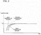
FIG. 2 is a graph depicting a relation between a detected temperature of each sensor and time. -
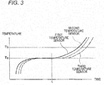
FIG. 3 is a graph depicting a relation between the detected temperature of each sensor and time when an abnormality has occurred in a motor. -
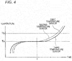
FIG. 4 is a graph depicting a relation between the detected temperature of each sensor and time when an abnormality has occurred in a bearing. -
FIG. 5 is a graph depicting a relation between the detected temperature of each sensor and time when an abnormality has occurred in a pump. -
FIG. 6 is a schematic view of an abnormality diagnosis system in accordance with a second illustrative embodiment. - Hereinafter, an abnormality diagnosis system in accordance with each illustrative embodiment of the present invention will be described with reference to the drawings.
- As shown in
FIG. 1 , an abnormality diagnosis system 1 of a first illustrative embodiment includes a rolling bearing 10, a plurality ofsensors abnormality diagnosis device 30 configured to diagnose abnormalities of the rolling bearing 10 and a variety of devices (for example, amotor 41 and a pump 42) on the basis of signals output from the plurality ofsensors - The rolling
bearing 10 includes an outer ring 11(a fixed ring) having an outerring raceway surface 11a formed on an inner peripheral surface thereof, an inner ring 13 (a rotary ring) having an innerring raceway surface 13a formed on an outer peripheral surface thereof, a plurality ofballs 15 disposed to be rollable between the outerring raceway surface 11a and the innerring raceway surface 13a, aretainer 17 configured to hold the plurality ofballs 15 to be rollable and a pair ofseal members 19 fixed at both axial sides of the inner peripheral surface of theouter ring 11. That is, the rollingbearing 10 includes a plurality of components such as theouter ring 11, theinner ring 13, theball 15, theretainer 17, theseal member 19 and the like. - The
inner ring 13 is a rotary ring externally fitted and fixed to a shaft 3 and configured to rotate together with the shaft 3. At one axial end-side (a left side inFIG. 1 ) of the rolling bearing 10, a motor 41 (a device) is fixed to the shaft 3 and the shaft 3 is configured to be rotatively driven by a rotor (not shown) of themotor 41. Also, at the other axial end-side (a right side inFIG. 1 ) of the rollingbearing 10, apump 42 is fixed to the shaft 3, and a driving force of themotor 41 is transmitted to thepump 42 via the shaft 3. - The
outer ring 11 is a fixed ring internally fitted and fixed to a housing (not shown) and configured not to rotate. The inner peripheral surface of theouter ring 11 is formed at both axial sides of the outerring raceway surface 11a with a pair ofseal grooves 11b for fixing the pair ofseal members 19 thereto. Each of the pair ofseal members 19 is a non-contact type extending radially and configured to face the outer peripheral surface of theinner ring 13 via a gap. Thereby, the pair ofseal members 19 is configured to seal a space between theouter ring 11 and theinner ring 13 and to prevent foreign matters from being introduced into the bearing from an outside. Also, the not-contacttype seal members 19 are used, so that it is possible to suppress an influence on temperature detection of temperature sensors (which will be described later). - In the first illustrative embodiment, the machine device includes the rotary shaft 3, the housing, the rolling
bearing 10, themotor 41 as a first device disposed at one axial end-side of the rollingbearing 10 and thepump 42 as a second device disposed at the other axial end-side of the rollingbearing 10. - Also, the first to
third sensors outer ring 11. In the first illustrative embodiment, the plurality ofsensors first temperature sensor 21 disposed in the vicinity of one axial end portion of theouter ring 11, asecond temperature sensor 22 disposed at an axially central portion in the vicinity of the outerring raceway surface 11a, and athird temperature sensor 23 disposed in the vicinity of the other axial end portion. - Meanwhile, in the first illustrative embodiment, the plurality of
sensors - The temperatures to be detected by the first to
third temperature sensors 21 to 23 are influenced by heat to be generated from the rollingbearing 10, themotor 41 and thepump 42. At this time, the influence levels are different depending on the disposition positions. That is, thefirst temperature sensor 21 disposed in the vicinity of themotor 41 is likely to be influenced by a change in temperature of themotor 41, thesecond temperature sensor 22 disposed in the vicinity of theball 15, theinner ring 13 or the like is likely to be influenced by a change in temperature of the rollingbearing 10, and thethird temperature sensor 23 disposed in the vicinity of thepump 42 is likely to be influenced by a change in temperature of thepump 42. - The first to
third temperature sensors 21 to 23 are configured to output the detected temperatures and to transmit the same to theabnormality diagnosis device 30. Theabnormality diagnosis device 30 is a microcomputer, for example. A program recorded in the microcomputer is executed, so that respective units such as adata collection unit 31 execute following processing. - A
data collection unit 31 of theabnormality diagnosis device 30 is configured to collect the output data from the first tothird temperature sensors 21 to 23. Adata processing unit 33 of theabnormality diagnosis device 30 is configured to process the collected output data and to store the respective output data. Astate determination unit 35 of theabnormality diagnosis device 30 is configured to specify a sensor of which an output value first increases from a rated temperature or first exceeds a predetermined threshold value from the first tothird temperature sensor 21 to 23. Also, thestate determination unit 35 is configured to determine which of the rollingbearing 10, themotor 41 and thepump 42 is abnormal, based on a position at which the specified sensor (hereinafter, referred to as 'specific sensor') is disposed. - For example, when the
first temperature sensor 21 is the specific sensor, it is determined that themotor 41 is abnormal because thefirst temperature sensor 21 is disposed in the vicinity of themotor 41, as compared to the second andthird temperature sensors second temperature sensor 22 is the specific sensor, it is determined that the rollingbearing 10 is abnormal because thesecond temperature sensor 22 is disposed in the vicinity of theball 15, theinner ring 13 or the like, as compared to the third andfirst temperature sensors third temperature sensor 23 is the specific sensor, it is determined that thepump 42 is abnormal because thethird temperature sensor 23 is disposed in the vicinity of thepump 42, as compared to the first andsecond temperature sensors - In a machine facility in which the abnormality diagnosis system 1 is incorporated, the
bearing 10, themotor 41 and thepump 42 generate the heat, and times of temperature rising thereof are different. For this reason, as shown inFIG. 2 , temperature rising curves obtained from the output values of the first tothird temperature sensors 21 to 23 are different immediately after the machine facility starts. However, at a steady state after predetermined time, since the temperature of theouter ring 11 becomes the same as the environment temperature around the rollingbearing 10, there is no difference in temperatures to be detected by the first tothird temperature sensors 21 to 23, so that the temperatures become a rated temperature Ta. - Herein, a case where the
motor 41 abnormally generates heat due to any cause at time t after the rated temperature Ta is described with reference toFIG. 3 . In this case, the output value of thefirst temperature sensor 21 disposed in the vicinity of themotor 41, as compared to the second andthird temperature sensors second temperature sensor 22 and thethird temperature sensor 23. Then, the output values exceed a predetermined threshold value Tb in order of thefirst temperature sensor 21, thesecond temperature sensor 22 and thethird temperature sensor 23. - Therefore, the
abnormality diagnosis device 30 specifies thefirst temperature sensor 21, as the sensor of which the output value first increases or the sensor of which the output value first exceeds the threshold value Tb. Then, the abnormality diagnosis device determines that themotor 41 is abnormal, based on the position at which thefirst temperature sensor 21 is disposed, i.e., based on the configuration where thefirst temperature sensor 21 is disposed in the vicinity of themotor 41. - Subsequently, a case where the rolling
bearing 10 abnormally generates heat due to causes such as seizing, wear and the like at time t after the rated temperature Ta is described with reference toFIG. 4 . In this case, the output value of thesecond temperature sensor 22 disposed in the vicinity of the rollingbearing 10, as compared to the third andfirst temperature sensors third temperature sensor 23 and thefirst temperature sensor 21. Then, the output value of thesecond temperature sensor 22 first exceeds the threshold value Tb and the output values of thethird temperature sensor 23 and thefirst temperature sensor 21 exceed the threshold value Tb. - Therefore, the
abnormality diagnosis device 30 specifies thesecond temperature sensor 22, as the sensor of which the output value first increases or the sensor of which the output value first exceeds the threshold value Tb. Then, the abnormality diagnosis device determines that the rollingbearing 10 is abnormal, based on the position at which thesecond temperature sensor 22 is disposed, i.e., based on the configuration where thesecond temperature sensor 22 is disposed in the vicinity of the rollingbearing 10. - Subsequently, a case where the
pump 42 abnormally generates heat due to any cause at time t after the rated temperature Ta is described with reference toFIG. 5 . In this case, the output value of thethird temperature sensor 23 disposed in the vicinity of the pump, as compared to the first andsecond temperature sensors second temperature sensor 22 and thefirst temperature sensor 21. Then, the output values exceed the predetermined threshold value Tb in order of thethird temperature sensor 23, thesecond temperature sensor 22 and thefirst temperature sensor 21. - Therefore, the
abnormality diagnosis device 30 specifies thethird temperature sensor 23, as the sensor of which the output value first increases or the sensor of which the output value first exceeds the threshold value Tb. Then, the abnormality diagnosis device determines that thepump 42 is abnormal, based on the position at which thethird temperature sensor 23 is disposed, i.e., based on the configuration where thethird temperature sensor 23 is disposed in the vicinity of thepump 42. - Like this, according to the abnormality diagnosis system 1 of the first illustrative embodiment, it is possible to effectively perform the abnormality diagnosis of the rolling
bearing 10 and the abnormality diagnosis of the devices (themotor 41 and the pump 42) disposed around the rollingbearing 10. - In the below, an abnormality diagnosis system 1 in accordance with a second illustrative embodiment of the present invention is described with reference to
FIG. 6 . In the meantime, the parts, which are the same or equivalent to those of the first illustrative embodiment, are denoted with the same reference numerals and the descriptions thereof are omitted or simplified. - In the first illustrative embodiment, the plurality of
sensors 21 to 23 is disposed at the different positions of theouter ring 11, which is the fixed ring. However, in the second illustrative embodiment, the plurality ofsensors inner ring 13, which is the rotary ring. That is, in the second illustrative embodiment, the plurality ofsensors first temperature sensor 21 disposed in the vicinity of one axial end portion of theinner ring 13, thesecond temperature sensor 22 disposed at the axially central portion in the vicinity of the innerring raceway surface 13a and thethird temperature sensor 23 disposed in the vicinity of the other axial end portion. - Therefore, also in the second illustrative embodiment, the
first temperature sensor 21 disposed in the vicinity of themotor 41 is likely to be influenced by a change in temperature of themotor 41, thesecond temperature sensor 22 disposed in the vicinity of theball 15, theouter ring 11 or the like is likely to be influenced by a change in temperature of the rollingbearing 10, and thethird temperature sensor 23 disposed in the vicinity of thepump 42 is likely to be influenced by a change in temperature of thepump 42. - Also in the second illustrative embodiment, like
FIG. 2 of the first illustrative embodiment, the temperature rising curves obtained from the output values of the first tothird temperature sensors 21 to 23 are different immediately after the machine facility starts. Also, at a steady state after predetermined time, since the temperature of theinner ring 13 becomes the same as the environment temperature around the rollingbearing 10, there is no difference in temperatures to be detected by the first tothird temperature sensors 21 to 23, so that the temperatures become the rated temperature Ta. - Therefore, also in the second illustrative embodiment, it is possible to determine whether any one of the
motor 41, the rollingbearing 10 and thepump 42 is abnormal, based on the graphs depicting the output values of the first tothird temperature sensor 21 to 23, which are shown inFIGS. 3 to 5 . - Like this, according to the abnormality diagnosis system I of the second illustrative embodiment, it is possible to effectively perform the abnormality diagnosis of the rolling
bearing 10 and the abnormality diagnosis of the devices (themotor 41 and the pump 42) disposed around the rollingbearing 10. - The other configurations and effects are the same as the first illustrative embodiment.
- In the meantime, the present invention is not limited to the illustrative embodiments and can be appropriately changed and improved.
- For example, the
abnormality diagnosis device 30 may be configured not only to specify a sensor of which an output value first increases or a sensor of which an output value first exceeds the predetermined threshold value Tb but also to specify a sensor of which an output value secondarily increases or a sensor of which an output value second exceeds the threshold value Tb. Then, theabnormality diagnosis device 30 is configured to determine which of the rollingbearing 10 and the devices is abnormal, based on a position of the sensor first specified and a position of the sensor second specified. Thereby, it is possible to more correctly determine the part at which the heat is generated and to improve the precision of the abnormality determination. Likewise, theabnormality diagnosis device 30 may be configured to determine which of the rollingbearing 10 and the devices is abnormal, based on a position of the sensor first specified, a position of the sensor second specified and a position of the sensor third specified. - Also, the number of sensors to be provided is not particularly limited inasmuch as a plurality of sensors is provided, and may increase or decrease in connection with a machine device to which the abnormality diagnosis system is to be incorporated. For example, in the illustrative embodiments, when the
pump 42 is not provided, thethird temperature sensor 23 may not be provided, - Also, the sensor to be provided is not particularly limited inasmuch as it can monitor the state of the rolling
bearing 10 or the device (for example, themotor 41 or the pump 42) disposed around the rolling bearing. For example, a vibration sensor or a load sensor may be adopted. Herein, like the illustrative embodiment, when the sensor is disposed at theinner ring 13, which is the rotary ring, heat, vibration, load and the like are to be transmitted from the shaft 3. Therefore, it is possible to rapidly detect the behavior, as compared to the configuration where the sensor is provided at the other component of the rollingbearing 10. - When the load sensor is adopted as the sensor to be provided, if the load sensor is disposed at the
outer ring 11, which is the fixed ring, the load sensor should be disposed in a load zone, which limits a disposition phase on a circumference. However, when the load sensor is disposed at theinner ring 13, which is the rotary ring, like the second illustrative embodiment, the disposition phase is not limited, so that it is possible to dispose a plurality of load sensors with being spaced on the circumference. For this reason, when the load sensors are disposed one by one at any phase on the circumference, it is possible to detect the behaviors at the respective phases. That is, when the load sensors are disposed at the rotary ring, one load sensor may be disposed at a phase on one circumference, without disposing the plurality of load sensors at phases on the same circumference. Therefore, the plurality of load sensors is disposed at different positions, as seen from an axial direction. - Also, the disposition position of the sensor is not limited to the
outer ring 11 or theinner ring 13 inasmuch as it is disposed at a component of the rollingbearing 10. For example, theretainer 17 or theseal member 19 is also possible. - Also, the signal transmission method from the sensor to the
data collection unit 31 of theabnormality diagnosis device 30 may be any method, irrespective of whether it is a wired or wireless method. - When the
abnormality diagnosis device 30 determines the abnormalities of the rollingbearing 10, themotor 41 and thepump 42, the abnormality diagnosis device may notify the abnormalities to an upper system so as to automatically stop the machine facility or issue a warning to an operator and a manager with an alarm, a screen display and the like. - The devices to be disposed around the rolling
bearing 10 are not limited to themotor 41 and thepump 42, and any device can be adopted. - The subject application is based on a Japanese Patent Application No.
2015-030986 filed on February 19, 2015 2015-030987 filed on February 19, 2015 -
- 1: abnormality diagnosis system
- 10: bearing
- 11: outer ring (component, fixed ring)
- 13: inner ring (component, rotary ring)
- 15: ball (component)
- 17: retainer (component)
- 19: seal member (component)
- 21: first temperature sensor
- 22: second temperature sensor
- 23: third temperature sensor
- 30: abnormality diagnosis device
- 31: data collection unit
- 33: data processing unit
- 35: state determination unit
- 41: motor (device)
- 42: pump (device)
Claims (9)
- An abnormality diagnosis system comprising:a bearing that has a plurality of components;a plurality of sensors that are disposed at different positions of the component and that are configured to detect surrounding signals; andan abnormality diagnosis device that is configured to diagnose abnormality of the bearing and abnormality of a device disposed around the bearing, based on signals output from the plurality of sensors.
- The abnormality diagnosis system according to claim 1, wherein the components include an inner ring or an outer ring, and
wherein the plurality of sensors comprises:a first sensor which is disposed in the vicinity of one axial end portion of the inner ring or outer ring of the bearing;a second sensor which is disposed in the vicinity of a raceway surface of the inner ring or outer ring of the bearing; anda third sensor which is disposed in the vicinity of the other axial end portion of the inner ring or outer ring of the bearing. - The abnormality diagnosis system according to claim 2, wherein the outer ring is a fixed ring.
- The abnormality diagnosis system according to claim 2, wherein the inner ring is a rotary ring.
- The abnormality diagnosis system according to any one of claims 1 to 4, wherein the abnormality diagnosis device is configured to specify a sensor which output value firstly increases or which output value firstly exceeds a predetermined threshold value, from the plurality of sensors and to determine which of the bearing and the devices is abnormal, based on a position at which the specified sensor is disposed.
- The abnormality diagnosis system according to any one of claims 1 to 5, wherein the plurality of sensors is respectively temperature sensors.
- The abnormality diagnosis system according to any one of claims 1 to 5, wherein the plurality of sensors is respectively vibration sensors.
- The abnormality diagnosis system according to any one of claims 1 to 5, wherein the plurality of sensors is respectively load sensors.
- The abnormality diagnosis system according to claim 8, wherein the plurality of sensors is not disposed on a same circumference.
Applications Claiming Priority (3)
| Application Number | Priority Date | Filing Date | Title |
|---|---|---|---|
| JP2015030987 | 2015-02-19 | ||
| JP2015030986 | 2015-02-19 | ||
| PCT/JP2016/054498 WO2016133100A1 (en) | 2015-02-19 | 2016-02-17 | Abnormality diagnosis system |
Publications (3)
| Publication Number | Publication Date |
|---|---|
| EP3260838A1 true EP3260838A1 (en) | 2017-12-27 |
| EP3260838A4 EP3260838A4 (en) | 2018-02-28 |
| EP3260838B1 EP3260838B1 (en) | 2021-03-24 |
Family
ID=56688995
Family Applications (1)
| Application Number | Title | Priority Date | Filing Date |
|---|---|---|---|
| EP16752486.7A Not-in-force EP3260838B1 (en) | 2015-02-19 | 2016-02-17 | Abnormality diagnosis system |
Country Status (5)
| Country | Link |
|---|---|
| US (1) | US10260991B2 (en) |
| EP (1) | EP3260838B1 (en) |
| JP (1) | JPWO2016133100A1 (en) |
| CN (1) | CN107250754A (en) |
| WO (1) | WO2016133100A1 (en) |
Families Citing this family (5)
| Publication number | Priority date | Publication date | Assignee | Title |
|---|---|---|---|---|
| DK3208571T3 (en) * | 2016-02-18 | 2019-03-04 | Siemens Ag | Device for measuring bearing |
| JP6408063B1 (en) | 2017-04-28 | 2018-10-17 | ファナック株式会社 | Machine head spindle failure detection device having a plurality of sensors |
| JP6499718B2 (en) * | 2017-06-19 | 2019-04-10 | ファナック株式会社 | Abnormal wear detection device for seal member and rotating body device |
| JP7169084B2 (en) * | 2017-09-28 | 2022-11-10 | Ntn株式会社 | Condition monitoring device and condition monitoring system |
| WO2019065952A1 (en) * | 2017-09-28 | 2019-04-04 | Ntn株式会社 | State monitoring device and state monitoring system |
Family Cites Families (13)
| Publication number | Priority date | Publication date | Assignee | Title |
|---|---|---|---|---|
| JPS62169034A (en) * | 1986-01-22 | 1987-07-25 | Hitachi Ltd | Bearing diagnosis device for rotating machinery |
| JPH0447964U (en) * | 1990-08-31 | 1992-04-23 | ||
| GB2295207B (en) * | 1994-11-08 | 1998-04-08 | Torrington Co | Bearing with a sensor arrangement for obtaining an indication of various parameters within the housing of the bearing |
| IT1309554B1 (en) | 1999-03-04 | 2002-01-23 | Skf Ind Spa | BEARING GROUP FOR A RAILWAY AXLE. |
| JP3874110B2 (en) * | 2002-08-30 | 2007-01-31 | 日本精工株式会社 | Abnormality diagnosis system |
| AU2003264360A1 (en) | 2002-08-30 | 2004-04-08 | Nsk Ltd. | Method and device for monitoring status of mechanical equipment and abnormality diagnosing device |
| JP2007088380A (en) * | 2005-09-26 | 2007-04-05 | Fanuc Ltd | Laser oscillator blower and laser oscillator |
| JP5607285B2 (en) * | 2006-06-23 | 2014-10-15 | 日本精工株式会社 | Bearing device |
| JP2009109350A (en) | 2007-10-30 | 2009-05-21 | Jfe Advantech Co Ltd | Monitoring and diagnosing system for rotary machine apparatus |
| JP2009191898A (en) * | 2008-02-13 | 2009-08-27 | Nsk Ltd | Bearing with sensor and manufacturing method thereof |
| JP2010162634A (en) * | 2009-01-14 | 2010-07-29 | Jtekt Corp | Spindle device |
| JP5725833B2 (en) | 2010-01-04 | 2015-05-27 | Ntn株式会社 | Rolling bearing abnormality diagnosis device, wind power generation device and abnormality diagnosis system |
| JPWO2016175322A1 (en) * | 2015-04-30 | 2018-02-22 | 日本精工株式会社 | Abnormality diagnosis system |
-
2016
- 2016-02-17 US US15/549,544 patent/US10260991B2/en active Active
- 2016-02-17 WO PCT/JP2016/054498 patent/WO2016133100A1/en not_active Ceased
- 2016-02-17 CN CN201680010961.8A patent/CN107250754A/en active Pending
- 2016-02-17 JP JP2017500697A patent/JPWO2016133100A1/en active Pending
- 2016-02-17 EP EP16752486.7A patent/EP3260838B1/en not_active Not-in-force
Also Published As
| Publication number | Publication date |
|---|---|
| EP3260838A4 (en) | 2018-02-28 |
| WO2016133100A1 (en) | 2016-08-25 |
| CN107250754A (en) | 2017-10-13 |
| US20180038772A1 (en) | 2018-02-08 |
| JPWO2016133100A1 (en) | 2017-11-30 |
| EP3260838B1 (en) | 2021-03-24 |
| US10260991B2 (en) | 2019-04-16 |
Similar Documents
| Publication | Publication Date | Title |
|---|---|---|
| EP3290895A1 (en) | Abnormality diagnosis system | |
| US10260991B2 (en) | Abnormality diagnosis system | |
| JP6308922B2 (en) | Rolling bearing abnormality diagnosis apparatus, wind power generation apparatus, and rolling bearing abnormality diagnosis method | |
| US10024758B2 (en) | Abnormality detecting device having function for detecting abnormality of machine tool, and abnormality detecting method | |
| US9689777B2 (en) | Fault detection for bearings | |
| JP6657256B2 (en) | Fault diagnosis method and fault diagnosis device for feed axis | |
| JP2006077938A (en) | Abnormality diagnosis device | |
| KR102697028B1 (en) | Abnormal diagnosis method and abnormal diagnosis device of cloud bearing | |
| CN106493607A (en) | The bearing diagnosis device of lathe | |
| EP3266709A1 (en) | Bearing monitoring system for an air cycle machine and method of monitoring | |
| JP6637844B2 (en) | Method for determining warm-up operation time before bearing diagnosis in machine tool, machine tool | |
| CN107843429A (en) | Bearing state monitoring control method and control device, monitoring equipment and monitoring method | |
| JP7351142B2 (en) | Rolling bearing condition monitoring method and condition monitoring device | |
| JP2017003555A (en) | Sensor unit, bearing with sensor, and abnormality diagnosis system | |
| JP7552507B2 (en) | Method and device for diagnosing abnormalities in rolling bearings | |
| EP4105501B1 (en) | State determination device for hub unit bearing, state determination method for hub unit bearing, program, and hub unit bearing | |
| JP2018040456A (en) | Rotary shaft device and abnormality diagnostic method of bearing on rotary shaft device | |
| CN111649944A (en) | Bearing diagnosis device, bearing diagnosis method, and escalator | |
| JP7057760B2 (en) | Abnormality diagnosis system for rotary electric machines | |
| EP3433595B1 (en) | Method to monitor a thrust load on a rolling bearing and machinery equipped with a system to monitor said thrust load | |
| CN113056620A (en) | Bearing device | |
| WO2016199846A1 (en) | Sensor unit, sensor-equipped bearing and abnormality diagnosis system | |
| JP2021018102A (en) | Bearing abnormality prediction device and bearing abnormality prediction method | |
| JP2021018106A (en) | Bearing abnormality prediction device and bearing abnormality prediction method | |
| US20180299341A1 (en) | Method And Device For Imbalance Detection |
Legal Events
| Date | Code | Title | Description |
|---|---|---|---|
| STAA | Information on the status of an ep patent application or granted ep patent |
Free format text: STATUS: THE INTERNATIONAL PUBLICATION HAS BEEN MADE |
|
| PUAI | Public reference made under article 153(3) epc to a published international application that has entered the european phase |
Free format text: ORIGINAL CODE: 0009012 |
|
| STAA | Information on the status of an ep patent application or granted ep patent |
Free format text: STATUS: REQUEST FOR EXAMINATION WAS MADE |
|
| 17P | Request for examination filed |
Effective date: 20170802 |
|
| AK | Designated contracting states |
Kind code of ref document: A1 Designated state(s): AL AT BE BG CH CY CZ DE DK EE ES FI FR GB GR HR HU IE IS IT LI LT LU LV MC MK MT NL NO PL PT RO RS SE SI SK SM TR |
|
| AX | Request for extension of the european patent |
Extension state: BA ME |
|
| A4 | Supplementary search report drawn up and despatched |
Effective date: 20180129 |
|
| RIC1 | Information provided on ipc code assigned before grant |
Ipc: G01M 99/00 20110101ALI20180123BHEP Ipc: G01M 13/04 20060101AFI20180123BHEP |
|
| DAV | Request for validation of the european patent (deleted) | ||
| DAX | Request for extension of the european patent (deleted) | ||
| STAA | Information on the status of an ep patent application or granted ep patent |
Free format text: STATUS: EXAMINATION IS IN PROGRESS |
|
| 17Q | First examination report despatched |
Effective date: 20190116 |
|
| GRAP | Despatch of communication of intention to grant a patent |
Free format text: ORIGINAL CODE: EPIDOSNIGR1 |
|
| STAA | Information on the status of an ep patent application or granted ep patent |
Free format text: STATUS: GRANT OF PATENT IS INTENDED |
|
| INTG | Intention to grant announced |
Effective date: 20201112 |
|
| GRAS | Grant fee paid |
Free format text: ORIGINAL CODE: EPIDOSNIGR3 |
|
| GRAA | (expected) grant |
Free format text: ORIGINAL CODE: 0009210 |
|
| STAA | Information on the status of an ep patent application or granted ep patent |
Free format text: STATUS: THE PATENT HAS BEEN GRANTED |
|
| AK | Designated contracting states |
Kind code of ref document: B1 Designated state(s): AL AT BE BG CH CY CZ DE DK EE ES FI FR GB GR HR HU IE IS IT LI LT LU LV MC MK MT NL NO PL PT RO RS SE SI SK SM TR |
|
| REG | Reference to a national code |
Ref country code: GB Ref legal event code: FG4D |
|
| REG | Reference to a national code |
Ref country code: CH Ref legal event code: EP |
|
| REG | Reference to a national code |
Ref country code: IE Ref legal event code: FG4D |
|
| REG | Reference to a national code |
Ref country code: AT Ref legal event code: REF Ref document number: 1374981 Country of ref document: AT Kind code of ref document: T Effective date: 20210415 Ref country code: DE Ref legal event code: R096 Ref document number: 602016054840 Country of ref document: DE |
|
| REG | Reference to a national code |
Ref country code: LT Ref legal event code: MG9D |
|
| PG25 | Lapsed in a contracting state [announced via postgrant information from national office to epo] |
Ref country code: NO Free format text: LAPSE BECAUSE OF FAILURE TO SUBMIT A TRANSLATION OF THE DESCRIPTION OR TO PAY THE FEE WITHIN THE PRESCRIBED TIME-LIMIT Effective date: 20210624 Ref country code: FI Free format text: LAPSE BECAUSE OF FAILURE TO SUBMIT A TRANSLATION OF THE DESCRIPTION OR TO PAY THE FEE WITHIN THE PRESCRIBED TIME-LIMIT Effective date: 20210324 Ref country code: HR Free format text: LAPSE BECAUSE OF FAILURE TO SUBMIT A TRANSLATION OF THE DESCRIPTION OR TO PAY THE FEE WITHIN THE PRESCRIBED TIME-LIMIT Effective date: 20210324 Ref country code: GR Free format text: LAPSE BECAUSE OF FAILURE TO SUBMIT A TRANSLATION OF THE DESCRIPTION OR TO PAY THE FEE WITHIN THE PRESCRIBED TIME-LIMIT Effective date: 20210625 Ref country code: BG Free format text: LAPSE BECAUSE OF FAILURE TO SUBMIT A TRANSLATION OF THE DESCRIPTION OR TO PAY THE FEE WITHIN THE PRESCRIBED TIME-LIMIT Effective date: 20210624 |
|
| PG25 | Lapsed in a contracting state [announced via postgrant information from national office to epo] |
Ref country code: RS Free format text: LAPSE BECAUSE OF FAILURE TO SUBMIT A TRANSLATION OF THE DESCRIPTION OR TO PAY THE FEE WITHIN THE PRESCRIBED TIME-LIMIT Effective date: 20210324 Ref country code: LV Free format text: LAPSE BECAUSE OF FAILURE TO SUBMIT A TRANSLATION OF THE DESCRIPTION OR TO PAY THE FEE WITHIN THE PRESCRIBED TIME-LIMIT Effective date: 20210324 Ref country code: SE Free format text: LAPSE BECAUSE OF FAILURE TO SUBMIT A TRANSLATION OF THE DESCRIPTION OR TO PAY THE FEE WITHIN THE PRESCRIBED TIME-LIMIT Effective date: 20210324 |
|
| REG | Reference to a national code |
Ref country code: NL Ref legal event code: MP Effective date: 20210324 |
|
| REG | Reference to a national code |
Ref country code: AT Ref legal event code: MK05 Ref document number: 1374981 Country of ref document: AT Kind code of ref document: T Effective date: 20210324 |
|
| PG25 | Lapsed in a contracting state [announced via postgrant information from national office to epo] |
Ref country code: NL Free format text: LAPSE BECAUSE OF FAILURE TO SUBMIT A TRANSLATION OF THE DESCRIPTION OR TO PAY THE FEE WITHIN THE PRESCRIBED TIME-LIMIT Effective date: 20210324 |
|
| PG25 | Lapsed in a contracting state [announced via postgrant information from national office to epo] |
Ref country code: LT Free format text: LAPSE BECAUSE OF FAILURE TO SUBMIT A TRANSLATION OF THE DESCRIPTION OR TO PAY THE FEE WITHIN THE PRESCRIBED TIME-LIMIT Effective date: 20210324 Ref country code: EE Free format text: LAPSE BECAUSE OF FAILURE TO SUBMIT A TRANSLATION OF THE DESCRIPTION OR TO PAY THE FEE WITHIN THE PRESCRIBED TIME-LIMIT Effective date: 20210324 Ref country code: CZ Free format text: LAPSE BECAUSE OF FAILURE TO SUBMIT A TRANSLATION OF THE DESCRIPTION OR TO PAY THE FEE WITHIN THE PRESCRIBED TIME-LIMIT Effective date: 20210324 Ref country code: SM Free format text: LAPSE BECAUSE OF FAILURE TO SUBMIT A TRANSLATION OF THE DESCRIPTION OR TO PAY THE FEE WITHIN THE PRESCRIBED TIME-LIMIT Effective date: 20210324 Ref country code: AT Free format text: LAPSE BECAUSE OF FAILURE TO SUBMIT A TRANSLATION OF THE DESCRIPTION OR TO PAY THE FEE WITHIN THE PRESCRIBED TIME-LIMIT Effective date: 20210324 |
|
| PG25 | Lapsed in a contracting state [announced via postgrant information from national office to epo] |
Ref country code: IS Free format text: LAPSE BECAUSE OF FAILURE TO SUBMIT A TRANSLATION OF THE DESCRIPTION OR TO PAY THE FEE WITHIN THE PRESCRIBED TIME-LIMIT Effective date: 20210724 Ref country code: SK Free format text: LAPSE BECAUSE OF FAILURE TO SUBMIT A TRANSLATION OF THE DESCRIPTION OR TO PAY THE FEE WITHIN THE PRESCRIBED TIME-LIMIT Effective date: 20210324 Ref country code: RO Free format text: LAPSE BECAUSE OF FAILURE TO SUBMIT A TRANSLATION OF THE DESCRIPTION OR TO PAY THE FEE WITHIN THE PRESCRIBED TIME-LIMIT Effective date: 20210324 Ref country code: PT Free format text: LAPSE BECAUSE OF FAILURE TO SUBMIT A TRANSLATION OF THE DESCRIPTION OR TO PAY THE FEE WITHIN THE PRESCRIBED TIME-LIMIT Effective date: 20210726 Ref country code: PL Free format text: LAPSE BECAUSE OF FAILURE TO SUBMIT A TRANSLATION OF THE DESCRIPTION OR TO PAY THE FEE WITHIN THE PRESCRIBED TIME-LIMIT Effective date: 20210324 |
|
| REG | Reference to a national code |
Ref country code: DE Ref legal event code: R097 Ref document number: 602016054840 Country of ref document: DE |
|
| PG25 | Lapsed in a contracting state [announced via postgrant information from national office to epo] |
Ref country code: DK Free format text: LAPSE BECAUSE OF FAILURE TO SUBMIT A TRANSLATION OF THE DESCRIPTION OR TO PAY THE FEE WITHIN THE PRESCRIBED TIME-LIMIT Effective date: 20210324 Ref country code: AL Free format text: LAPSE BECAUSE OF FAILURE TO SUBMIT A TRANSLATION OF THE DESCRIPTION OR TO PAY THE FEE WITHIN THE PRESCRIBED TIME-LIMIT Effective date: 20210324 Ref country code: ES Free format text: LAPSE BECAUSE OF FAILURE TO SUBMIT A TRANSLATION OF THE DESCRIPTION OR TO PAY THE FEE WITHIN THE PRESCRIBED TIME-LIMIT Effective date: 20210324 |
|
| PLBE | No opposition filed within time limit |
Free format text: ORIGINAL CODE: 0009261 |
|
| STAA | Information on the status of an ep patent application or granted ep patent |
Free format text: STATUS: NO OPPOSITION FILED WITHIN TIME LIMIT |
|
| PG25 | Lapsed in a contracting state [announced via postgrant information from national office to epo] |
Ref country code: SI Free format text: LAPSE BECAUSE OF FAILURE TO SUBMIT A TRANSLATION OF THE DESCRIPTION OR TO PAY THE FEE WITHIN THE PRESCRIBED TIME-LIMIT Effective date: 20210324 |
|
| 26N | No opposition filed |
Effective date: 20220104 |
|
| PG25 | Lapsed in a contracting state [announced via postgrant information from national office to epo] |
Ref country code: IS Free format text: LAPSE BECAUSE OF FAILURE TO SUBMIT A TRANSLATION OF THE DESCRIPTION OR TO PAY THE FEE WITHIN THE PRESCRIBED TIME-LIMIT Effective date: 20210724 |
|
| PG25 | Lapsed in a contracting state [announced via postgrant information from national office to epo] |
Ref country code: MC Free format text: LAPSE BECAUSE OF FAILURE TO SUBMIT A TRANSLATION OF THE DESCRIPTION OR TO PAY THE FEE WITHIN THE PRESCRIBED TIME-LIMIT Effective date: 20210324 |
|
| REG | Reference to a national code |
Ref country code: CH Ref legal event code: PL |
|
| REG | Reference to a national code |
Ref country code: BE Ref legal event code: MM Effective date: 20220228 |
|
| GBPC | Gb: european patent ceased through non-payment of renewal fee |
Effective date: 20220217 |
|
| PG25 | Lapsed in a contracting state [announced via postgrant information from national office to epo] |
Ref country code: LU Free format text: LAPSE BECAUSE OF NON-PAYMENT OF DUE FEES Effective date: 20220217 |
|
| PG25 | Lapsed in a contracting state [announced via postgrant information from national office to epo] |
Ref country code: FR Free format text: LAPSE BECAUSE OF NON-PAYMENT OF DUE FEES Effective date: 20220228 |
|
| PG25 | Lapsed in a contracting state [announced via postgrant information from national office to epo] |
Ref country code: LI Free format text: LAPSE BECAUSE OF NON-PAYMENT OF DUE FEES Effective date: 20220228 Ref country code: IT Free format text: LAPSE BECAUSE OF FAILURE TO SUBMIT A TRANSLATION OF THE DESCRIPTION OR TO PAY THE FEE WITHIN THE PRESCRIBED TIME-LIMIT Effective date: 20210324 Ref country code: IE Free format text: LAPSE BECAUSE OF NON-PAYMENT OF DUE FEES Effective date: 20220217 Ref country code: GB Free format text: LAPSE BECAUSE OF NON-PAYMENT OF DUE FEES Effective date: 20220217 Ref country code: CH Free format text: LAPSE BECAUSE OF NON-PAYMENT OF DUE FEES Effective date: 20220228 |
|
| PG25 | Lapsed in a contracting state [announced via postgrant information from national office to epo] |
Ref country code: BE Free format text: LAPSE BECAUSE OF NON-PAYMENT OF DUE FEES Effective date: 20220228 |
|
| PG25 | Lapsed in a contracting state [announced via postgrant information from national office to epo] |
Ref country code: HU Free format text: LAPSE BECAUSE OF FAILURE TO SUBMIT A TRANSLATION OF THE DESCRIPTION OR TO PAY THE FEE WITHIN THE PRESCRIBED TIME-LIMIT; INVALID AB INITIO Effective date: 20160217 |
|
| PG25 | Lapsed in a contracting state [announced via postgrant information from national office to epo] |
Ref country code: MK Free format text: LAPSE BECAUSE OF FAILURE TO SUBMIT A TRANSLATION OF THE DESCRIPTION OR TO PAY THE FEE WITHIN THE PRESCRIBED TIME-LIMIT Effective date: 20210324 Ref country code: CY Free format text: LAPSE BECAUSE OF FAILURE TO SUBMIT A TRANSLATION OF THE DESCRIPTION OR TO PAY THE FEE WITHIN THE PRESCRIBED TIME-LIMIT Effective date: 20210324 |
|
| PGFP | Annual fee paid to national office [announced via postgrant information from national office to epo] |
Ref country code: DE Payment date: 20231228 Year of fee payment: 9 |
|
| PG25 | Lapsed in a contracting state [announced via postgrant information from national office to epo] |
Ref country code: MT Free format text: LAPSE BECAUSE OF FAILURE TO SUBMIT A TRANSLATION OF THE DESCRIPTION OR TO PAY THE FEE WITHIN THE PRESCRIBED TIME-LIMIT Effective date: 20210324 |
|
| REG | Reference to a national code |
Ref country code: DE Ref legal event code: R119 Ref document number: 602016054840 Country of ref document: DE |
|
| PG25 | Lapsed in a contracting state [announced via postgrant information from national office to epo] |
Ref country code: TR Free format text: LAPSE BECAUSE OF FAILURE TO SUBMIT A TRANSLATION OF THE DESCRIPTION OR TO PAY THE FEE WITHIN THE PRESCRIBED TIME-LIMIT Effective date: 20210324 |
|
| PG25 | Lapsed in a contracting state [announced via postgrant information from national office to epo] |
Ref country code: DE Free format text: LAPSE BECAUSE OF NON-PAYMENT OF DUE FEES Effective date: 20250902 |