EP3260753A1 - Nozzle for grease application - Google Patents
Nozzle for grease application Download PDFInfo
- Publication number
- EP3260753A1 EP3260753A1 EP16752258.0A EP16752258A EP3260753A1 EP 3260753 A1 EP3260753 A1 EP 3260753A1 EP 16752258 A EP16752258 A EP 16752258A EP 3260753 A1 EP3260753 A1 EP 3260753A1
- Authority
- EP
- European Patent Office
- Prior art keywords
- grease
- worm wheel
- discharge port
- concave
- nozzle
- Prior art date
- Legal status (The legal status is an assumption and is not a legal conclusion. Google has not performed a legal analysis and makes no representation as to the accuracy of the status listed.)
- Granted
Links
Images




Classifications
-
- B—PERFORMING OPERATIONS; TRANSPORTING
- B05—SPRAYING OR ATOMISING IN GENERAL; APPLYING FLUENT MATERIALS TO SURFACES, IN GENERAL
- B05C—APPARATUS FOR APPLYING FLUENT MATERIALS TO SURFACES, IN GENERAL
- B05C5/00—Apparatus in which liquid or other fluent material is projected, poured or allowed to flow on to the surface of the work
- B05C5/02—Apparatus in which liquid or other fluent material is projected, poured or allowed to flow on to the surface of the work the liquid or other fluent material being discharged through an outlet orifice by pressure, e.g. from an outlet device in contact or almost in contact, with the work
- B05C5/0254—Coating heads with slot-shaped outlet
-
- B—PERFORMING OPERATIONS; TRANSPORTING
- B05—SPRAYING OR ATOMISING IN GENERAL; APPLYING FLUENT MATERIALS TO SURFACES, IN GENERAL
- B05B—SPRAYING APPARATUS; ATOMISING APPARATUS; NOZZLES
- B05B1/00—Nozzles, spray heads or other outlets, with or without auxiliary devices such as valves, heating means
- B05B1/26—Nozzles, spray heads or other outlets, with or without auxiliary devices such as valves, heating means with means for mechanically breaking-up or deflecting the jet after discharge, e.g. with fixed deflectors; Breaking-up the discharged liquid or other fluent material by impinging jets
-
- B—PERFORMING OPERATIONS; TRANSPORTING
- B05—SPRAYING OR ATOMISING IN GENERAL; APPLYING FLUENT MATERIALS TO SURFACES, IN GENERAL
- B05C—APPARATUS FOR APPLYING FLUENT MATERIALS TO SURFACES, IN GENERAL
- B05C11/00—Component parts, details or accessories not specifically provided for in groups B05C1/00 - B05C9/00
- B05C11/02—Apparatus for spreading or distributing liquids or other fluent materials already applied to a surface ; Controlling means therefor; Control of the thickness of a coating by spreading or distributing liquids or other fluent materials already applied to the coated surface
- B05C11/023—Apparatus for spreading or distributing liquids or other fluent materials already applied to a surface
- B05C11/028—Apparatus for spreading or distributing liquids or other fluent materials already applied to a surface with a body having a large flat spreading or distributing surface
-
- B—PERFORMING OPERATIONS; TRANSPORTING
- B05—SPRAYING OR ATOMISING IN GENERAL; APPLYING FLUENT MATERIALS TO SURFACES, IN GENERAL
- B05C—APPARATUS FOR APPLYING FLUENT MATERIALS TO SURFACES, IN GENERAL
- B05C11/00—Component parts, details or accessories not specifically provided for in groups B05C1/00 - B05C9/00
- B05C11/02—Apparatus for spreading or distributing liquids or other fluent materials already applied to a surface ; Controlling means therefor; Control of the thickness of a coating by spreading or distributing liquids or other fluent materials already applied to the coated surface
- B05C11/04—Apparatus for spreading or distributing liquids or other fluent materials already applied to a surface ; Controlling means therefor; Control of the thickness of a coating by spreading or distributing liquids or other fluent materials already applied to the coated surface with blades
-
- B—PERFORMING OPERATIONS; TRANSPORTING
- B05—SPRAYING OR ATOMISING IN GENERAL; APPLYING FLUENT MATERIALS TO SURFACES, IN GENERAL
- B05D—PROCESSES FOR APPLYING FLUENT MATERIALS TO SURFACES, IN GENERAL
- B05D3/00—Pretreatment of surfaces to which liquids or other fluent materials are to be applied; After-treatment of applied coatings, e.g. intermediate treating of an applied coating preparatory to subsequent applications of liquids or other fluent materials
- B05D3/12—Pretreatment of surfaces to which liquids or other fluent materials are to be applied; After-treatment of applied coatings, e.g. intermediate treating of an applied coating preparatory to subsequent applications of liquids or other fluent materials by mechanical means
-
- F—MECHANICAL ENGINEERING; LIGHTING; HEATING; WEAPONS; BLASTING
- F16—ENGINEERING ELEMENTS AND UNITS; GENERAL MEASURES FOR PRODUCING AND MAINTAINING EFFECTIVE FUNCTIONING OF MACHINES OR INSTALLATIONS; THERMAL INSULATION IN GENERAL
- F16H—GEARING
- F16H57/00—General details of gearing
- F16H57/04—Features relating to lubrication or cooling or heating
- F16H57/0463—Grease lubrication; Drop-feed lubrication
- F16H57/0464—Grease lubrication
-
- F—MECHANICAL ENGINEERING; LIGHTING; HEATING; WEAPONS; BLASTING
- F16—ENGINEERING ELEMENTS AND UNITS; GENERAL MEASURES FOR PRODUCING AND MAINTAINING EFFECTIVE FUNCTIONING OF MACHINES OR INSTALLATIONS; THERMAL INSULATION IN GENERAL
- F16N—LUBRICATING
- F16N11/00—Arrangements for supplying grease from a stationary reservoir or the equivalent in or on the machine or member to be lubricated; Grease cups
- F16N11/08—Arrangements for supplying grease from a stationary reservoir or the equivalent in or on the machine or member to be lubricated; Grease cups with mechanical drive, other than directly by springs or weights
-
- F—MECHANICAL ENGINEERING; LIGHTING; HEATING; WEAPONS; BLASTING
- F16—ENGINEERING ELEMENTS AND UNITS; GENERAL MEASURES FOR PRODUCING AND MAINTAINING EFFECTIVE FUNCTIONING OF MACHINES OR INSTALLATIONS; THERMAL INSULATION IN GENERAL
- F16N—LUBRICATING
- F16N3/00—Devices for supplying lubricant by manual action
- F16N3/10—Devices for supplying lubricant by manual action delivering grease
-
- F—MECHANICAL ENGINEERING; LIGHTING; HEATING; WEAPONS; BLASTING
- F16—ENGINEERING ELEMENTS AND UNITS; GENERAL MEASURES FOR PRODUCING AND MAINTAINING EFFECTIVE FUNCTIONING OF MACHINES OR INSTALLATIONS; THERMAL INSULATION IN GENERAL
- F16N—LUBRICATING
- F16N5/00—Apparatus with hand-positioned nozzle supplied with lubricant under pressure
- F16N5/02—Nozzles or nozzle-valve arrangements therefor, e.g. high-pressure grease guns
-
- B—PERFORMING OPERATIONS; TRANSPORTING
- B05—SPRAYING OR ATOMISING IN GENERAL; APPLYING FLUENT MATERIALS TO SURFACES, IN GENERAL
- B05C—APPARATUS FOR APPLYING FLUENT MATERIALS TO SURFACES, IN GENERAL
- B05C5/00—Apparatus in which liquid or other fluent material is projected, poured or allowed to flow on to the surface of the work
- B05C5/02—Apparatus in which liquid or other fluent material is projected, poured or allowed to flow on to the surface of the work the liquid or other fluent material being discharged through an outlet orifice by pressure, e.g. from an outlet device in contact or almost in contact, with the work
- B05C5/0225—Apparatus in which liquid or other fluent material is projected, poured or allowed to flow on to the surface of the work the liquid or other fluent material being discharged through an outlet orifice by pressure, e.g. from an outlet device in contact or almost in contact, with the work characterised by flow controlling means, e.g. valves, located proximate the outlet
-
- B—PERFORMING OPERATIONS; TRANSPORTING
- B05—SPRAYING OR ATOMISING IN GENERAL; APPLYING FLUENT MATERIALS TO SURFACES, IN GENERAL
- B05C—APPARATUS FOR APPLYING FLUENT MATERIALS TO SURFACES, IN GENERAL
- B05C5/00—Apparatus in which liquid or other fluent material is projected, poured or allowed to flow on to the surface of the work
- B05C5/02—Apparatus in which liquid or other fluent material is projected, poured or allowed to flow on to the surface of the work the liquid or other fluent material being discharged through an outlet orifice by pressure, e.g. from an outlet device in contact or almost in contact, with the work
- B05C5/0241—Apparatus in which liquid or other fluent material is projected, poured or allowed to flow on to the surface of the work the liquid or other fluent material being discharged through an outlet orifice by pressure, e.g. from an outlet device in contact or almost in contact, with the work for applying liquid or other fluent material to elongated work, e.g. wires, cables, tubes
Definitions
- the present invention relates to improvements on a nozzle for grease application configured to apply grease to a member to be applied such as a worm wheel having a concave-convex part (a tooth part) formed on an outer peripheral surface or an inner peripheral surface thereof.
- gears are incorporated in a power transmission part of an automobile and a variety of industrial machines, and meshing portions between the gears are lubricated by grease.
- high-viscosity grease Japanese Industrial Standard consistency number is 3 or greater
- meshing portions between worm teeth of a worm shaft and worm wheel teeth of a worm wheel configuring a worm-type reducer to be incorporated in an electric power steering device are lubricated by the high-viscosity grease.
- the worm shaft and the worm wheel are mounted to each other at a state where the grease is applied to at least one of the worm teeth and the worm wheel teeth.
- a following method is considered, for example.
- Discharge ports configured to discharge the grease are intermittently provided in a circumferential direction with being brought close to the concave-convex part. Then, the grease is discharged from each discharge port towards the concave-convex part.
- Patent Document 1 discloses a technology of applying a fluid (paint 12) having a certain degree of viscosity to (a part of) a cylindrical surface of a member to be applied (a base material 5) by using a so-called plane nozzle (a nozzle 6).
- a nozzle 6 plane nozzle
- the nozzle disclosed in Patent Document 1 does not consider applying the high-viscosity grease to the circumferential concave-convex part.
- the grease may not be sufficiently sent into the concave portions of the concave-convex part.
- Patent Document 1 Japanese Patent Application Publication No. Hei 10-156254A
- the present invention has been made in view of the above situations, and an object thereof is to implement a structure of a nozzle for grease application capable of securely pushing grease into concave portions of a concave-convex part of a member to be applied and preventing the member to be applied, an application device and the like from being dirtied due to extra grease.
- a nozzle for grease application of the present invention has a discharge port provided to open towards a tip end face of a body part.
- a discharge port provided to open towards a tip end face of a body part.
- a member to be applied such as a gear, for example, while the member to be applied is rotated about a central axis thereof
- high-viscosity grease is discharged from the discharge port, so that the grease is continuously applied to the concave-convex part from a front side towards a rear side of the member to be applied with respect to a rotational direction thereof.
- the tip end face of the body part is provided at a part in front of the discharge port with respect to the rotational direction of the member to be applied with a grease-pushing surface part configured to push (fill) the grease into concave portions of the concave-convex part while raking and leveling the grease discharged from the discharge port and attached to the concave-convex part so that the grease is substantially uniform in a width direction and in a circumferential direction of the concave-convex part.
- the tip end face of the body part is provided at a rear part of the discharge port with respect to the rotational direction of the member to be applied with a protruding wall part protruding from the tip end face of the body part and configured to prevent a surplus of the grease raked and leveled by the grease-pushing surface part from moving rearwards with respect to the rotational direction of the member to be applied.
- the grease-pushing surface part is provided on a tip end face of a protruding part protruding from the tip end face of the body part and provided at a part of the tip end face of the body part in front of the discharge port with respect to the rotational direction of the member to be applied.
- the protruding part is configured by a plurality of projections intermittently provided in a width direction of the body part.
- a width dimension of the discharge port is made smaller than a width dimension of the concave-convex part, and both a width dimension of the protruding wall part and a width dimension of the grease-pushing surface part are made equal to or greater than the width dimension of the concave-convex part.
- the nozzle for grease application of the present invention configured as described above, it is possible to securely push the grease into concave portions of the concave-convex part of the member to be applied (to securely fill the grease into the concave portions) and preventing the member to be applied, an application device and the like from being dirtied due to the extra grease.
- the tip end face of the body part is provided at the part in front of the discharge port with respect to the rotational direction of the member to be applied with the grease-pushing surface part, and the grease discharged from the discharge port and attached to the concave-convex part is raked, leveled and pushed into the concave portions of the concave-convex part by the grease-pushing surface part. Therefore, it is possible to securely supply the grease into the concave portions of the concave-convex part (to evenly spread the grease in the entire concave portions).
- the tip end face of the body part is provided at the rear part of the discharge port with respect to the rotational direction of the member to be applied with the protruding wall part.
- FIGS. 1 to 6 depict a first example of an embodiment of the present invention.
- a feature of the present invention including the first example, is a structure of a nozzle for grease application 5 for securely sending high-viscosity (gel phase) grease 1 into concave portions (portions between respective teeth configuring worm wheel teeth 3) of the worm wheel teeth (a concave-convex part) 3 of a worm wheel 2, which is a member to be applied, and preventing the worm wheel 2, a grease application device 4 and the like from being dirtied due to the extra grease 1.
- high-viscosity (gel phase) grease 1 into concave portions (portions between respective teeth configuring worm wheel teeth 3) of the worm wheel teeth (a concave-convex part) 3 of a worm wheel 2, which is a member to be applied, and preventing the worm wheel 2, a grease application device 4 and the like from being dirtied due to the extra grease 1.
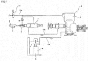
- a basic structure of the grease application device 4 for applying the grease 1 introduced from a grease pump 6 to the worm wheel teeth 3 of the worm wheel 2 by a grease application gun 7 is similar to that of the grease application device that has been known in the related art. First, the structure of the grease application device 4 is described with reference to FIG. 1 .
- the grease application device 4 includes a grease pump 6, a continuous flow valve 8 and a grease application gun 7.
- the grease pump 6 is to supply (to pneumatically transport) the grease 1 stored in a grease receptacle 9 to the continuous flow valve 8 through a hose 10a.
- the continuous flow valve 8 is to send the grease 1 to the grease application gun 7 through a hose 10b after adjusting a flow rate and a flow velocity of the grease 1 pneumatically transported from the grease pump 6.
- the grease application gun 7 is to discharge (push out) the grease 1, which is sent from the continuous flow valve 8, from a nozzle for grease application 5 mounted to a tip portion of the gun by a compressed air sent from a compressed air source 11 through a hose 10c and to apply the grease to the worm wheel teeth 3 of the worm wheel 2.
- the nozzle for grease application 5 is made by assembling a plurality of components formed by injection molding of a synthetic resin, and has a mounting part 12 and a body part 13.
- the mounting part 12 has a hollow cylindrical shape, and is mounted to the tip portion of the grease application gun 7 by internally fitting and fixing an outer peripheral surface or externally fitting and fixing an inner peripheral surface to the tip portion of the grease application gun 7.
- the body part 13 is provided to be continuous to the mounting part 12 at a downstream side (a lower side in FIGS. 2 to 4B ) of the mounting part 12 with respect to a flowing direction (an upper and lower direction in FIGS. 2 to 4B ) ⁇ of the grease 1 flowing in the nozzle for grease application 5.
- a tip end face (a lower end face in FIGS.
- a width dimension (an axial dimension of the worm wheel 2) W 14 of the discharge port 14 is made smaller than a width dimension W 3 of the worm wheel teeth 3 (W 14 ⁇ W 3 ).
- the width dimension W 14 of the discharge port 14 is set to about 12mm.
- a degree by which the width dimension W 14 of the discharge port 14 is made smaller than the width dimensionW 13 of the worm wheel teeth 3 is determined in design, in accordance with an amount (an applying thickness) and a viscosity of the grease 1 to be applied, a tooth depth (depths of the concave portions) of the worm wheel teeth 3, and the like. Also, a plurality of (three, in the shown example) column parts 15, 15 is provided to bridge over inner surfaces of the body part 13 so as to rectify the flow of the grease 1 flowing in the body part 13.
- the column parts 15, 15 are arranged at an upstream side of the discharge port 14 with respect to the flowing direction ⁇ of the grease. If the column parts 15, 15 are not provided, a discharge rate of the grease is not uniform in the width direction of the discharge port 14. Since the grease is supplied from a supply passage provided in the mounting part 12, the discharge rate is high in an area of the discharge port 14 in front of (on an extension line of) the mounting part 12 and is lower at both ends of the discharge port 14, The column parts 15, 15 are provided so as to suppress the non-uniformity of the discharge rate.
- the tip end face of the body part 13 is inclined in a direction facing towards a downstream side (a lower side in FIGS. 2 and 3 ) of the flowing direction ⁇ as it goes towards one side (a front side with respect to a rotational direction ⁇ of the worm wheel 2, which will be described later; a left side in FIGS. 2 and 3 ) of a direction ⁇ perpendicular to the width direction of the nozzle for grease application 5 and the flowing direction ⁇ of the grease 1 flowing in the nozzle for grease application 5.
- the tip end face of the body part 13 is provided at a part (i.e., one side part of the discharge port 14 perpendicular to the width direction of the discharge port 14) adjacent to one side of the discharge port 14 with respect to the direction ⁇ with a protruding part 16 protruding towards a downstream side with respect to the flowing direction ⁇ .
- a tip end face of the protruding part 16 is configured as a grease-pushing surface part 17 for raking and leveling the grease 1 discharged from the discharge port 14 above the worm wheel teeth 3 and sending the grease into the concave portions of the worm wheel teeth 3.
- the tip end face of the body part 13 is provided at a part (i.e., the other side part of the discharge port 14 perpendicular to the width direction of the discharge port 14) adjacent to the other side (a rear side with respect to the rotational direction ⁇ of the worm wheel 2) of the discharge port 14 with respect to the direction ⁇ with a protruding wall part 18 protruding towards a downstream side with respect to the flowing direction ⁇ .
- both a width dimension W 17 of the grease-pushing surface part 17 and a width dimension W 18 of the protruding wall part 18 are made equal to or greater than the width dimension W 3 of the worm wheel teeth 3 (W 17 ⁇ W 3 , W 18 ⁇ W 3 ).
- the interval d 16 between the worm wheel teeth 3 and the protruding part 16 is determined depending on the amount (an applying thickness) of the grease 1 to be applied to the worm wheel teeth 3, and is about 1.5mm, for example.
- the interval d 18 between the worm wheel teeth 3 and the protruding wall part 18 is preferably set as small as possible inasmuch as it is possible to prevent interference (contact) between the worm wheel teeth 3 and the protruding wall part 18 when applying the grease I, and can be set to about 0.5mm, for example.
- a position to which the discharge port 14 is brought close is a position offset to one side of the direction ⁇ from a virtual plane ⁇ passing to a central axis of the worm wheel 2 and parallel with the flowing direction ⁇ .
- an arrangement direction of the nozzle for grease application 5 (the flowing direction ⁇ of the grease 1 flowing in the nozzle for grease application 5) may be a vertical or horizontal direction.
- the worm wheel 2 is rotated at a constant speed in a counterclockwise direction ⁇ of FIGS. 2 and 3 by a driving source such as an electric motor or the like (not shown).
- a driving source such as an electric motor or the like (not shown).
- the grease 1 stored in the grease receptacle 9 is sent into the grease application gun 7 via the grease pump 6 and the continuous flow valve 8.
- the grease 1 sent into the grease application gun 7 is discharged at a constant flow rate towards the worm wheel teeth 3 from the discharge port 14 of the nozzle for grease application 5 mounted to the tip portion of the grease application gun 7.
- the grease 1 discharged from the discharge port 14 and attached to the worm wheel teeth 3 is pressed and crushed by the grease-pushing surface part 17 provided on the tip end face of the protruding part 16 as the worm wheel 2 is rotated. Thereby, the grease 1 is raked and leveled and is sent into the concave portions of the worm wheel teeth 3 (filled in the concave portions of the worm wheel teeth 3). That is, as shown with a range A in FIG.
- a width dimension w A of the grease 1 attached to the worm wheel teeth 3 immediately after it is discharged from the discharge port 14 is substantially the same as the width dimension W 14 of the discharge port 14 and is smaller than the width dimension W 3 of the worm wheel teeth 3 (w A ⁇ W 14 ⁇ W 3 ). From this state, the grease 1 attached to the worm wheel teeth 3 is pressed and crushed by the grease-pushing surface part 17, as the worm wheel 2 is rotated. As a result, as shown with a range B in FIG.
- the thickness of the grease 1 is raked and leveled so as to be substantially uniform in the width direction and in the circumferential direction of the worm wheel teeth 3 so that a width dimension w B of the grease 1 attached to the worm wheel teeth 3 is to be the same as the width dimension W 3 of the worm wheel teeth 3, and a part of the grease is sent into the concave portions of the worm wheel teeth 3. Therefore, it is possible to securely send the grease 1 into the concave portions of the worm wheel teeth 3 (to evenly spread the grease in the entire concave portions).
- the tip end face of the body part 13 is provided with the protruding wall part 18, so that the grease I discharged from the discharge port 14 is prevented from moving rearwards (an opposite direction to an arrow ⁇ in FIG. 3 ) with respect to the rotational direction of the worm wheel 2 between the tip end face of the body part 13 and the worm wheel teeth 3. That is, as shown in FIGS.
- a surplus of grease 1a discharged from a discharge port 14a, attached to the worm wheel teeth 3 and pressed and crushed by a grease-pushing surface part 17a moves in an arrow ⁇ direction (the rear of the rotational direction of the worm wheel 2) between a tip end face of the body part 13a and the worm wheel teeth 3.
- the surplus of the grease 1a is attached/deposited to a side surface of the body part 13a (a rear surface (a right surface in FIG. 7 ) with respect to the rotational direction of the worm wheel 2).
- a side surface of the body part 13a a rear surface (a right surface in FIG. 7 ) with respect to the rotational direction of the worm wheel 2.
- the width dimension W 14 of the discharge port 14 is made smaller than the width dimension W 3 of the worm wheel teeth 3 (W 14 ⁇ W 3 ), even when the grease is pressed and crushed by the grease-pushing surface part 17a, the grease 1 attached to the worm wheel teeth 3 is difficult to be redundant.
- the tip end face of the body part 13 is provided at a part close to the rear side of the discharge port 14 with respect to the rotational direction of the worm wheel 2 with the protruding wall part 18.
- the nozzle for grease application 5 of the first example it is possible to prevent the surplus of the grease 1 from being attached/deposited to the side surface of the body part 13 (the rear surface with respect to the rotational direction of the worm wheel 2), so that it is possible to prevent the worm wheel 2 and the grease application device 4 from being dirtied.
- the worm wheel 2 is rotated at a constant angular velocity, and the flow rate of the grease 1 to be discharged from the nozzle for grease application 5 is constant.
- a rotational phase of the worm wheel 2 is detected, and the rotating speed of the worm wheel 2 is slowed down at a state where the discharge port 14 faces the concave portions of the worm wheel teeth 3.
- the rotating speed of the worm wheel 2 is slowed down at a state where the discharge port 14 faces the concave portions of the worm wheel teeth 3.
- FIGS. 9A to 10C depict a second example of the embodiment of the present invention.
- a protruding part 16a provided on a tip end face of a body part 13b is configured by a plurality of (five, in the shown example) projections 19, 19.
- the respective projections 19, 19 have a substantially triangular shape, as seen from the rotational direction of the worm wheel 2, and are intermittently provided on the tip end face of the body part 13b in the width direction. That is, in the second example, a grease-pushing surface part 17b configured by tip end faces of the respective projections 19, 19 has a waveform.
- a width dimension (a dimension between tip portions of the projections 19, 19, which are located at both ends in the width direction, of the respective projections 19, 19) W 17b of the grease-pushing surface part 17b is made smaller than the width dimension W 3 of the worm wheel teeth 3 (W 17b ⁇ W 3 ).
- the nozzle for grease application 5b of the second example it is possible to adjust an amount of the grease 1 attached to the worm wheel teeth 3, which is to be pressed and crushed by the grease-pushing surface part 17b. Therefore, it is possible to reduce an amount of the grease 1 moving rearwards with respect to the rotational direction of the worm wheel 2 between the tip end face of the body part 13b and the worm wheel teeth 3. Also, since the grease-pushing surface part 17b is formed to have a waveform, it is possible to further increase the favorable adhesion of the grease I to the worm wheel teeth 3. That is, at a state where the worm wheel is taken out from a processing device, the cutting oil used to form the worm wheel teeth is attached to the worm wheel teeth.
- the grease-pushing surface part 17b is formed to have a waveform, so that as the worm wheel 2 is rotated, the grease 1 attached to the worm wheel teeth 3 is stirred by the grease-pushing surface part 17b (the grease 1 is pushed in the width direction by the respective projections 19, 19) and is pressed and crushed (pressed towards the worm wheel teeth 3).
- the grease 1 is likely to flow outwards in the width direction at both end portions of the grease-pushing surface part 17b in the width direction. Therefore, even when the pressed and crushed amount of the grease 1 is adjusted, it is possible to rake and level the grease 1 so that the thickness of the grease 1 is substantially to be uniform over the worm wheel teeth 3 in the width direction (so that a sectional shape is to be a waveform conforming to the grease-pushing surface part 17b).
- the number and shapes of the respective projections can be appropriately changed. That is, for example, like a nozzle for grease application 5c shown in FIGS. 11A and 11B , the tip portions of the projections 19a, 19a may have a semispherical shape, or like a nozzle for grease application 5d shown in FIGS. 12A and 12B , the three projections 19b, 19b may be provided.
- the number and shapes of the projections are determined in design, in accordance with an amount and a viscosity of the grease to be applied to the concave-convex part of the member to be applied, depths of the concave portions configuring the concave-convex part, and the like.
- the nozzle for grease application of the present invention can be used to apply the grease not only to the worm wheel described in the respective examples of the embodiment but also to a variety of gear members having a concave-convex part formed on an inner or outer peripheral surface thereof.
- the present invention is based on a Japanese Patent Application No. 2015-027199 filed on February 16, 2015 , which is herein incorporated by reference.
Landscapes
- Engineering & Computer Science (AREA)
- General Engineering & Computer Science (AREA)
- Mechanical Engineering (AREA)
- Coating Apparatus (AREA)
- General Details Of Gearings (AREA)
- Application Of Or Painting With Fluid Materials (AREA)
Abstract
Description
- The present invention relates to improvements on a nozzle for grease application configured to apply grease to a member to be applied such as a worm wheel having a concave-convex part (a tooth part) formed on an outer peripheral surface or an inner peripheral surface thereof.
- Many gears are incorporated in a power transmission part of an automobile and a variety of industrial machines, and meshing portions between the gears are lubricated by grease. Particularly, in order to improve durability of each gear, high-viscosity grease (Japanese Industrial Standard consistency number is 3 or greater) is used in some cases. Specifically, for example, meshing portions between worm teeth of a worm shaft and worm wheel teeth of a worm wheel configuring a worm-type reducer to be incorporated in an electric power steering device are lubricated by the high-viscosity grease.
- The worm shaft and the worm wheel are mounted to each other at a state where the grease is applied to at least one of the worm teeth and the worm wheel teeth. As a method of applying the high-viscosity grease to a circumferential concave-convex part (a tooth part) formed on an outer peripheral surface or an inner peripheral surface of a worm wheel and the like, a following method is considered, for example. Discharge ports configured to discharge the grease are intermittently provided in a circumferential direction with being brought close to the concave-convex part. Then, the grease is discharged from each discharge port towards the concave-convex part. However, according to this method, it is difficult to uniformly apply the grease. In particular, there is a possibility that the grease will not be able to be pushed into concave portions of the concave-convex part (the grease will not be able to be uniformly spread in the concave portions).
-
Patent Document 1 discloses a technology of applying a fluid (paint 12) having a certain degree of viscosity to (a part of) a cylindrical surface of a member to be applied (a base material 5) by using a so-called plane nozzle (a nozzle 6). However, the nozzle disclosed inPatent Document 1 does not consider applying the high-viscosity grease to the circumferential concave-convex part. Thus, even when the grease is applied to the concave-convex part by using the nozzle disclosed inPatent Document 1, the grease may not be sufficiently sent into the concave portions of the concave-convex part. - In the meantime, the numbers in parentheses indicate reference numerals denoted in
Patent Document 1. - Patent Document 1: Japanese Patent Application Publication No.
Hei 10-156254A - The present invention has been made in view of the above situations, and an object thereof is to implement a structure of a nozzle for grease application capable of securely pushing grease into concave portions of a concave-convex part of a member to be applied and preventing the member to be applied, an application device and the like from being dirtied due to extra grease.
- A nozzle for grease application of the present invention has a discharge port provided to open towards a tip end face of a body part. At a state where the discharge port is brought close to a circumferential concave-convex part (a tooth part) formed on a circumferential surface (an outer peripheral surface or an inner peripheral surface) of a member to be applied such as a gear, for example, while the member to be applied is rotated about a central axis thereof, high-viscosity grease is discharged from the discharge port, so that the grease is continuously applied to the concave-convex part from a front side towards a rear side of the member to be applied with respect to a rotational direction thereof.
- Particularly, in the nozzle for grease application of the present invention, the tip end face of the body part is provided at a part in front of the discharge port with respect to the rotational direction of the member to be applied with a grease-pushing surface part configured to push (fill) the grease into concave portions of the concave-convex part while raking and leveling the grease discharged from the discharge port and attached to the concave-convex part so that the grease is substantially uniform in a width direction and in a circumferential direction of the concave-convex part.
- Also, the tip end face of the body part is provided at a rear part of the discharge port with respect to the rotational direction of the member to be applied with a protruding wall part protruding from the tip end face of the body part and configured to prevent a surplus of the grease raked and leveled by the grease-pushing surface part from moving rearwards with respect to the rotational direction of the member to be applied.
- When implementing the nozzle for grease application of the present invention, preferably, the grease-pushing surface part is provided on a tip end face of a protruding part protruding from the tip end face of the body part and provided at a part of the tip end face of the body part in front of the discharge port with respect to the rotational direction of the member to be applied.
- When implementing the present invention, preferably, the protruding part is configured by a plurality of projections intermittently provided in a width direction of the body part.
- When implementing the nozzle for grease application of the present invention, preferably, a width dimension of the discharge port is made smaller than a width dimension of the concave-convex part, and both a width dimension of the protruding wall part and a width dimension of the grease-pushing surface part are made equal to or greater than the width dimension of the concave-convex part.
- According to the nozzle for grease application of the present invention configured as described above, it is possible to securely push the grease into concave portions of the concave-convex part of the member to be applied (to securely fill the grease into the concave portions) and preventing the member to be applied, an application device and the like from being dirtied due to the extra grease.
- That is, the tip end face of the body part is provided at the part in front of the discharge port with respect to the rotational direction of the member to be applied with the grease-pushing surface part, and the grease discharged from the discharge port and attached to the concave-convex part is raked, leveled and pushed into the concave portions of the concave-convex part by the grease-pushing surface part. Therefore, it is possible to securely supply the grease into the concave portions of the concave-convex part (to evenly spread the grease in the entire concave portions).
- Also, the tip end face of the body part is provided at the rear part of the discharge port with respect to the rotational direction of the member to be applied with the protruding wall part. Thereby, it is possible to prevent the grease from moving rearwards with respect to the rotational direction of the member to be applied between the tip end face of the body part and the concave-convex part. As a result, it is possible to prevent a situation where the grease is attached/deposited to a rear surface of the body part with respect to the rotational direction of the member to be applied, is peeled off from the rear surface and dirties the member to be applied, an application device to which the nozzle for grease application is incorporated, and the like.
-
-
FIG. 1 is a pictorial view for illustrating a structure of a grease application device in which a nozzle for grease application in accordance with a first example of an embodiment of the present invention is incorporated. -
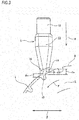
FIG. 2 depicts the nozzle for grease application of the first example and a worm wheel. -
FIG. 3 is an enlarged sectional view of an X part ofFIG. 2 . -
FIG. 4A is a perspective view of the nozzle for grease application, andFIG. 4B is an enlarged view of a Y part ofFIG. 4A . -
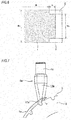
FIG. 5A depicts the nozzle for grease application, as seen from below ofFIG. 4A, and FIG. 5B depicts a part of an outer peripheral surface of the worm wheel, as seen from a radial direction. -
FIG. 6 illustrates a state of grease applied to worm wheel teeth. -
FIG. 7 is a similar view toFIG. 3 , illustrating a problem that is to occur when a protruding wall part is not provided. -
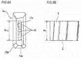
FIGS. 8A and 8B are similar views toFIG. 5 , illustrating a problem that is to occur when the protruding wall part is not provided. -
FIGS. 9A to 9C depict a second example of the embodiment of the present invention, in whichFIG. 9A is a perspective view,FIG. 9B is a side view andFIG. 9C is a bottom view, as seen from below ofFIG. 9B . -
FIG. 10A is an end view, as seen from the left ofFIG. 9C , andFIG. 10B is a similar view toFIG. 5B . -
FIGS. 11A and 11B depict a first example of another shape of the protruding part, in whichFIG. 11A is a perspective view andFIG. 11B is an end view. -
FIGS. 12A and 12B depict a second example of another shape of the protruding part and is similar toFIGS. 11A and 11B . -
FIGS. 1 to 6 depict a first example of an embodiment of the present invention. In the meantime, a feature of the present invention, including the first example, is a structure of a nozzle forgrease application 5 for securely sending high-viscosity (gel phase)grease 1 into concave portions (portions between respective teeth configuring worm wheel teeth 3) of the worm wheel teeth (a concave-convex part) 3 of aworm wheel 2, which is a member to be applied, and preventing theworm wheel 2, a grease application device 4 and the like from being dirtied due to theextra grease 1. A basic structure of the grease application device 4 for applying thegrease 1 introduced from agrease pump 6 to theworm wheel teeth 3 of theworm wheel 2 by a grease application gun 7 is similar to that of the grease application device that has been known in the related art. First, the structure of the grease application device 4 is described with reference toFIG. 1 . - The grease application device 4 includes a
grease pump 6, a continuous flow valve 8 and a grease application gun 7. Thegrease pump 6 is to supply (to pneumatically transport) thegrease 1 stored in a grease receptacle 9 to the continuous flow valve 8 through ahose 10a. The continuous flow valve 8 is to send thegrease 1 to the grease application gun 7 through ahose 10b after adjusting a flow rate and a flow velocity of thegrease 1 pneumatically transported from thegrease pump 6. The grease application gun 7 is to discharge (push out) thegrease 1, which is sent from the continuous flow valve 8, from a nozzle forgrease application 5 mounted to a tip portion of the gun by a compressed air sent from acompressed air source 11 through ahose 10c and to apply the grease to theworm wheel teeth 3 of theworm wheel 2. - In the first example, the nozzle for
grease application 5 is made by assembling a plurality of components formed by injection molding of a synthetic resin, and has a mountingpart 12 and abody part 13. The mountingpart 12 has a hollow cylindrical shape, and is mounted to the tip portion of the grease application gun 7 by internally fitting and fixing an outer peripheral surface or externally fitting and fixing an inner peripheral surface to the tip portion of the grease application gun 7. Thebody part 13 is provided to be continuous to the mountingpart 12 at a downstream side (a lower side inFIGS. 2 to 4B ) of the mountingpart 12 with respect to a flowing direction (an upper and lower direction inFIGS. 2 to 4B ) α of thegrease 1 flowing in the nozzle forgrease application 5. A tip end face (a lower end face inFIGS. 2 to 4B ) of thebody part 13 is provided with adischarge port 14 for discharging thegrease 1. In the first example, a width dimension (an axial dimension of the worm wheel 2) W14 of thedischarge port 14 is made smaller than a width dimension W3 of the worm wheel teeth 3 (W14<W3). Specifically, for example, when applying thegrease 1 to theworm wheel teeth 3, which is to be incorporated in an electric power steering device for automobile and has the width dimension W3 of about 16mm, the width dimension W14 of thedischarge port 14 is set to about 12mm. At this time, a degree by which the width dimension W14 of thedischarge port 14 is made smaller than the width dimensionW13 of theworm wheel teeth 3 is determined in design, in accordance with an amount (an applying thickness) and a viscosity of thegrease 1 to be applied, a tooth depth (depths of the concave portions) of theworm wheel teeth 3, and the like. Also, a plurality of (three, in the shown example)column parts body part 13 so as to rectify the flow of thegrease 1 flowing in thebody part 13. - The
column parts discharge port 14 with respect to the flowing direction α of the grease. If thecolumn parts discharge port 14. Since the grease is supplied from a supply passage provided in the mountingpart 12, the discharge rate is high in an area of thedischarge port 14 in front of (on an extension line of) the mountingpart 12 and is lower at both ends of thedischarge port 14, Thecolumn parts - The tip end face of the
body part 13 is inclined in a direction facing towards a downstream side (a lower side inFIGS. 2 and3 ) of the flowing direction α as it goes towards one side (a front side with respect to a rotational direction γ of theworm wheel 2, which will be described later; a left side inFIGS. 2 and3 ) of a direction β perpendicular to the width direction of the nozzle forgrease application 5 and the flowing direction α of thegrease 1 flowing in the nozzle forgrease application 5. Also, the tip end face of thebody part 13 is provided at a part (i.e., one side part of thedischarge port 14 perpendicular to the width direction of the discharge port 14) adjacent to one side of thedischarge port 14 with respect to the direction β with a protrudingpart 16 protruding towards a downstream side with respect to the flowing direction α. A tip end face of the protrudingpart 16 is configured as a grease-pushingsurface part 17 for raking and leveling thegrease 1 discharged from thedischarge port 14 above theworm wheel teeth 3 and sending the grease into the concave portions of theworm wheel teeth 3. In the meantime, the tip end face of thebody part 13 is provided at a part (i.e., the other side part of thedischarge port 14 perpendicular to the width direction of the discharge port 14) adjacent to the other side (a rear side with respect to the rotational direction γ of the worm wheel 2) of thedischarge port 14 with respect to the direction β with a protrudingwall part 18 protruding towards a downstream side with respect to the flowing direction α. In the first example, both a width dimension W17 of the grease-pushingsurface part 17 and a width dimension W18 of the protrudingwall part 18 are made equal to or greater than the width dimension W3 of the worm wheel teeth 3 (W17≥W3, W18≥W3). - When applying the high-
viscosity grease 1 to theworm wheel teeth 3 of theworm wheel 2 by the grease application device 4, as shown inFIGS. 2 and3 , thedischarge port 14 of the nozzle forgrease application 5 is brought close to theworm wheel teeth 3. At this state, an interval d16 between theworm wheel teeth 3 and the protrudingpart 16 with respect to the flowing direction α is made smaller than an interval d14 between thedischarge port 14 and the worm wheel teeth and greater than an interval d18 between the protrudingwall part 18 and the worm wheel teeth (d18<d16<d14). The interval d16 between theworm wheel teeth 3 and the protrudingpart 16 is determined depending on the amount (an applying thickness) of thegrease 1 to be applied to theworm wheel teeth 3, and is about 1.5mm, for example. In the meantime, the interval d18 between theworm wheel teeth 3 and the protrudingwall part 18 is preferably set as small as possible inasmuch as it is possible to prevent interference (contact) between theworm wheel teeth 3 and the protrudingwall part 18 when applying the grease I, and can be set to about 0.5mm, for example. Also, in the first example, a position to which thedischarge port 14 is brought close is a position offset to one side of the direction β from a virtual plane δ passing to a central axis of theworm wheel 2 and parallel with the flowing direction α. In the meantime, an arrangement direction of the nozzle for grease application 5 (the flowing direction α of thegrease 1 flowing in the nozzle for grease application 5) may be a vertical or horizontal direction. - In any case, at this state, the
worm wheel 2 is rotated at a constant speed in a counterclockwise direction γ ofFIGS. 2 and3 by a driving source such as an electric motor or the like (not shown). At the same time, thegrease 1 stored in the grease receptacle 9 is sent into the grease application gun 7 via thegrease pump 6 and the continuous flow valve 8. Then, thegrease 1 sent into the grease application gun 7 is discharged at a constant flow rate towards theworm wheel teeth 3 from thedischarge port 14 of the nozzle forgrease application 5 mounted to the tip portion of the grease application gun 7. - The
grease 1 discharged from thedischarge port 14 and attached to theworm wheel teeth 3 is pressed and crushed by the grease-pushingsurface part 17 provided on the tip end face of the protrudingpart 16 as theworm wheel 2 is rotated. Thereby, thegrease 1 is raked and leveled and is sent into the concave portions of the worm wheel teeth 3 (filled in the concave portions of the worm wheel teeth 3). That is, as shown with a range A inFIG. 6 , a width dimension wA of thegrease 1 attached to theworm wheel teeth 3 immediately after it is discharged from thedischarge port 14 is substantially the same as the width dimension W14 of thedischarge port 14 and is smaller than the width dimension W3 of the worm wheel teeth 3 (wA≒W14<W3). From this state, thegrease 1 attached to theworm wheel teeth 3 is pressed and crushed by the grease-pushingsurface part 17, as theworm wheel 2 is rotated. As a result, as shown with a range B inFIG. 6 , the thickness of thegrease 1 is raked and leveled so as to be substantially uniform in the width direction and in the circumferential direction of theworm wheel teeth 3 so that a width dimension wB of thegrease 1 attached to theworm wheel teeth 3 is to be the same as the width dimension W3 of theworm wheel teeth 3, and a part of the grease is sent into the concave portions of theworm wheel teeth 3. Therefore, it is possible to securely send thegrease 1 into the concave portions of the worm wheel teeth 3 (to evenly spread the grease in the entire concave portions). - Also, in the first example, the tip end face of the
body part 13 is provided with the protrudingwall part 18, so that the grease I discharged from thedischarge port 14 is prevented from moving rearwards (an opposite direction to an arrow γ inFIG. 3 ) with respect to the rotational direction of theworm wheel 2 between the tip end face of thebody part 13 and theworm wheel teeth 3. That is, as shown inFIGS. 7 to 8B , according to a nozzle forgrease application 5a having no protrudingwall part 18, a surplus ofgrease 1a discharged from adischarge port 14a, attached to theworm wheel teeth 3 and pressed and crushed by a grease-pushingsurface part 17a moves in an arrow ε direction (the rear of the rotational direction of the worm wheel 2) between a tip end face of thebody part 13a and theworm wheel teeth 3. Particularly, in the example shown inFIGS. 7 to 8B , a width dimension W14a of thedischarge port 14a and the width dimension W3 of theworm wheel teeth 3 are made to be the same (W14a=W3), so that thegrease 1a is likely to be extra grease. The surplus of thegrease 1a is attached/deposited to a side surface of thebody part 13a (a rear surface (a right surface inFIG. 7 ) with respect to the rotational direction of the worm wheel 2). When the grease is peeled off from the side surface of thebody part 13a, theworm wheel 2 and the grease application device 4 may be dirtied. - In contrast, according to the nozzle for
grease application 5 of the first example, since the width dimension W14 of thedischarge port 14 is made smaller than the width dimension W3 of the worm wheel teeth 3 (W14<W3), even when the grease is pressed and crushed by the grease-pushingsurface part 17a, thegrease 1 attached to theworm wheel teeth 3 is difficult to be redundant. Also, in the first example, the tip end face of thebody part 13 is provided at a part close to the rear side of thedischarge port 14 with respect to the rotational direction of theworm wheel 2 with the protrudingwall part 18. For this reason, when the surplus of thegrease 1 intends to move rearwards with respect to the rotational direction of theworm wheel 2 between the tip end face of thebody part 13 and theworm wheel teeth 3, the grease is blocked by the protrudingwall part 18. Meanwhile, in the first example, in order to prevent the interference between theworm wheel teeth 3 and the protrudingwall part 18, a slight gap (a gap of about 0.5mm) is formed between theworm wheel teeth 3 and the protrudingwall part 18. However, since the high-viscosity grease is used as thegrease 1, it is possible to prevent thegrease 1 from moving rearwards with respect to the rotational direction of theworm wheel 2 through the slight gap. Therefore, according to the nozzle forgrease application 5 of the first example, it is possible to prevent the surplus of thegrease 1 from being attached/deposited to the side surface of the body part 13 (the rear surface with respect to the rotational direction of the worm wheel 2), so that it is possible to prevent theworm wheel 2 and the grease application device 4 from being dirtied. - Meanwhile, in the first example, the
worm wheel 2 is rotated at a constant angular velocity, and the flow rate of thegrease 1 to be discharged from the nozzle forgrease application 5 is constant. However, it is possible to change the rotating speed of theworm wheel 2 at the state where the flow rate of thegrease 1 to be discharged from the nozzle forgrease application 5 is constant. Specifically, a rotational phase of theworm wheel 2 is detected, and the rotating speed of theworm wheel 2 is slowed down at a state where thedischarge port 14 faces the concave portions of theworm wheel teeth 3. Thereby, it is possible to securely send thegrease 1 into the concave portions of theworm wheel teeth 3. -
FIGS. 9A to 10C depict a second example of the embodiment of the present invention. In a nozzle forgrease application 5b of the second example, a protrudingpart 16a provided on a tip end face of abody part 13b is configured by a plurality of (five, in the shown example)projections respective projections worm wheel 2, and are intermittently provided on the tip end face of thebody part 13b in the width direction. That is, in the second example, a grease-pushingsurface part 17b configured by tip end faces of therespective projections projections respective projections 19, 19) W17b of the grease-pushingsurface part 17b is made smaller than the width dimension W3 of the worm wheel teeth 3 (W17b<W3). - According to the nozzle for
grease application 5b of the second example, it is possible to adjust an amount of thegrease 1 attached to theworm wheel teeth 3, which is to be pressed and crushed by the grease-pushingsurface part 17b. Therefore, it is possible to reduce an amount of thegrease 1 moving rearwards with respect to the rotational direction of theworm wheel 2 between the tip end face of thebody part 13b and theworm wheel teeth 3. Also, since the grease-pushingsurface part 17b is formed to have a waveform, it is possible to further increase the favorable adhesion of the grease I to theworm wheel teeth 3. That is, at a state where the worm wheel is taken out from a processing device, the cutting oil used to form the worm wheel teeth is attached to the worm wheel teeth. At this state, even when the grease is discharged towards the worm wheel teeth, an oil film of the cutting oil is interposed between the grease and the worm wheel teeth, so that it is not possible to obtain the sufficient adhesion. Therefore, when using the worm wheel, the grease may be peeled off due to a centrifugal force associated with the rotation of the worm wheel. In contrast, according to the second example, the grease-pushingsurface part 17b is formed to have a waveform, so that as theworm wheel 2 is rotated, thegrease 1 attached to theworm wheel teeth 3 is stirred by the grease-pushingsurface part 17b (thegrease 1 is pushed in the width direction by therespective projections 19, 19) and is pressed and crushed (pressed towards the worm wheel teeth 3). As a result, it is possible to destroy the oil film interposed between theworm wheel teeth 3 and thegrease 1, thereby further improving the adhesion of thegrease 1 to theworm wheel teeth 3. Meanwhile, in the second example, since therespective projections grease 1 is likely to flow outwards in the width direction at both end portions of the grease-pushingsurface part 17b in the width direction. Therefore, even when the pressed and crushed amount of thegrease 1 is adjusted, it is possible to rake and level thegrease 1 so that the thickness of thegrease 1 is substantially to be uniform over theworm wheel teeth 3 in the width direction (so that a sectional shape is to be a waveform conforming to the grease-pushingsurface part 17b). - When the protruding part is configured by the plurality of projections, like the second example, the number and shapes of the respective projections can be appropriately changed. That is, for example, like a nozzle for
grease application 5c shown inFIGS. 11A and 11B , the tip portions of theprojections grease application 5d shown inFIGS. 12A and 12B , the threeprojections - The configurations and operations of the other parts are the same as the first example of the embodiment.
- The nozzle for grease application of the present invention can be used to apply the grease not only to the worm wheel described in the respective examples of the embodiment but also to a variety of gear members having a concave-convex part formed on an inner or outer peripheral surface thereof.
- The present invention is based on a Japanese Patent Application No.
2015-027199 filed on February 16, 2015 -
- 1, 1a: grease
- 2: worm wheel
- 3: worm wheel teeth
- 4: grease application device
- 5, 5a to 5d: nozzle for grease application
- 6: grease pump
- 7: grease application gun
- 8: continuous flow valve
- 9: grease receptacle
- 10a to 10c: hose
- 11: compressed air source
- 12: mounting part
- 13, 13a: body part
- 14, 14a: discharge port
- 15: column part
- 16, 16a: protruding part
- 17, 17a, 17b: grease-pushing surface part
- 18: protruding wall part
- 19, 19a, 19b: projection
Claims (4)
- A nozzle for grease application comprising a discharge port provided to open towards a tip end face of a body part, wherein
at a state where the discharge port is close to a circumferential concave-convex part formed on a circumferential surface of a member to be applied, while the member to be applied is rotated about a central axis thereof, grease is discharged from the discharge port so that the grease is applied to the concave-convex part,
the tip end face of the body part is provided at a part in front of the discharge port with respect to a rotational direction of the member to be applied with a grease-pushing surface part configured to push the grease into concave portions of the concave-convex part while raking and leveling the grease discharged from the discharge port and attached to the concave-convex part, and
the tip end face of the body part is provided at a rear part of the discharge port with respect to the rotational direction of the member to be applied with a protruding wall part protruding from the tip end face of the body part and configured to prevent a surplus of the grease raked and leveled by the grease-pushing surface part from moving rearwards with respect to the rotational direction of the member to be applied. - The nozzle for grease application according to claim 1, wherein
the grease-pushing surface part is provided on a tip end face of a protruding part protruding from the tip end face of the body part and provided at a part of the tip end face of the body part in front of the discharge port with respect to the rotational direction of the member to be applied. - The nozzle for grease application according to claim 2, wherein
the protruding part is configured by a plurality of projections intermittently provided in a width direction of the body part. - The nozzle for grease application according to claim 1 or 2, wherein
a width dimension of the discharge port is smaller than a width dimension of the concave-convex part, and
both a width dimension of the protruding wall part and a width dimension of the grease-pushing surface part are equal to or greater than the width dimension of the concave-convex part.
Applications Claiming Priority (2)
| Application Number | Priority Date | Filing Date | Title |
|---|---|---|---|
| JP2015027199A JP6187496B2 (en) | 2015-02-16 | 2015-02-16 | Grease application nozzle |
| PCT/JP2016/052790 WO2016132869A1 (en) | 2015-02-16 | 2016-01-29 | Nozzle for grease application |
Publications (3)
| Publication Number | Publication Date |
|---|---|
| EP3260753A1 true EP3260753A1 (en) | 2017-12-27 |
| EP3260753A4 EP3260753A4 (en) | 2018-07-04 |
| EP3260753B1 EP3260753B1 (en) | 2020-03-04 |
Family
ID=56688837
Family Applications (1)
| Application Number | Title | Priority Date | Filing Date |
|---|---|---|---|
| EP16752258.0A Active EP3260753B1 (en) | 2015-02-16 | 2016-01-29 | Nozzle for grease application |
Country Status (5)
| Country | Link |
|---|---|
| US (1) | US10543505B2 (en) |
| EP (1) | EP3260753B1 (en) |
| JP (1) | JP6187496B2 (en) |
| CN (1) | CN107250655B (en) |
| WO (1) | WO2016132869A1 (en) |
Families Citing this family (7)
| Publication number | Priority date | Publication date | Assignee | Title |
|---|---|---|---|---|
| JP6634984B2 (en) * | 2016-09-02 | 2020-01-22 | 京セラドキュメントソリューションズ株式会社 | Liquid coating device |
| CN106334661B (en) * | 2016-11-30 | 2019-07-02 | 芜湖全程智能科技有限公司 | A kind of method of screw component coating lubricating oil rouge |
| JP6848758B2 (en) * | 2017-08-02 | 2021-03-24 | トヨタ自動車株式会社 | Film deposition equipment |
| CN107457151A (en) * | 2017-09-09 | 2017-12-12 | 芜湖润林包装材料有限公司 | Corrugated board corner protector glue flush coater |
| CN111577875B (en) * | 2020-04-02 | 2021-10-19 | 武汉船用机械有限责任公司 | Grease injection device |
| US12246522B2 (en) * | 2021-10-05 | 2025-03-11 | The Boeing Company | Nozzles and systems for adhesively attaching a first part to a second part |
| CN116753446A (en) * | 2023-06-06 | 2023-09-15 | 山东飞越电子科技有限公司 | A grease adding device for pan/tilt worm gear |
Family Cites Families (18)
| Publication number | Priority date | Publication date | Assignee | Title |
|---|---|---|---|---|
| US3854553A (en) * | 1973-11-01 | 1974-12-17 | Caterpillar Tractor Co | Lubrication system for swing gear drive |
| CA1138784A (en) * | 1979-01-03 | 1983-01-04 | Northwest Engineering Company | Mobile power crane-excavator with open gear greasing |
| US4244447A (en) * | 1979-01-08 | 1981-01-13 | Northwest Engineering Company | Mobile power crane-excavator with open gear greasing |
| JPH08233197A (en) * | 1995-03-01 | 1996-09-10 | Hitachi Constr Mach Co Ltd | Gear grease greasing device |
| US6117490A (en) | 1996-10-02 | 2000-09-12 | Matsushita Electric Industrial Co, Ltd. | Coating material application method and an apparatus for use in such a method |
| JP3482112B2 (en) * | 1996-10-02 | 2003-12-22 | 松下電器産業株式会社 | Coating method and device |
| US5925414A (en) * | 1996-11-20 | 1999-07-20 | International Business Corpration | Nozzle and method for extruding conductive paste into high aspect ratio openings |
| EP0919288A3 (en) * | 1997-11-25 | 2003-10-08 | Nordson Corporation | Electrostatic dispensing apparatus and method |
| US6902209B2 (en) * | 2002-08-15 | 2005-06-07 | Mcinerney Edward A. | Grease gun adaptor device |
| US7967768B2 (en) | 2003-04-14 | 2011-06-28 | Watts Robert J | Ankle-foot orthosis |
| US20070107773A1 (en) * | 2005-11-17 | 2007-05-17 | Palo Alto Research Center Incorporated | Bifacial cell with extruded gridline metallization |
| JP5276420B2 (en) * | 2008-01-31 | 2013-08-28 | 大日本スクリーン製造株式会社 | Substrate processing apparatus and substrate processing method |
| JP5290852B2 (en) * | 2009-04-23 | 2013-09-18 | 日置電機株式会社 | Flux coating apparatus and flux coating method |
| US9033109B2 (en) * | 2012-01-31 | 2015-05-19 | General Electric Company | System and method for lubricating gears in a wind turbine |
| JP6142268B2 (en) * | 2013-05-28 | 2017-06-07 | 兵神装備株式会社 | Discharge width variable device and discharge device |
| JP2015013272A (en) | 2013-07-08 | 2015-01-22 | トヨタ自動車株式会社 | Coating device and method |
| DE102014209101A1 (en) * | 2014-05-14 | 2015-11-19 | Skf Lubrication Systems Germany Gmbh | Dosing device for metered application of a grease to a surface, method for metered application of a grease to a surface |
| JP6265152B2 (en) * | 2015-03-02 | 2018-01-24 | 日本精工株式会社 | Grease application method and application device, worm speed reducer manufacturing method, electric power steering device manufacturing method, automobile manufacturing method and industrial machine manufacturing method |
-
2015
- 2015-02-16 JP JP2015027199A patent/JP6187496B2/en not_active Expired - Fee Related
-
2016
- 2016-01-29 US US15/548,139 patent/US10543505B2/en active Active
- 2016-01-29 CN CN201680010020.4A patent/CN107250655B/en active Active
- 2016-01-29 EP EP16752258.0A patent/EP3260753B1/en active Active
- 2016-01-29 WO PCT/JP2016/052790 patent/WO2016132869A1/en not_active Ceased
Also Published As
| Publication number | Publication date |
|---|---|
| EP3260753A4 (en) | 2018-07-04 |
| JP6187496B2 (en) | 2017-08-30 |
| CN107250655B (en) | 2019-09-27 |
| US20180036759A1 (en) | 2018-02-08 |
| WO2016132869A1 (en) | 2016-08-25 |
| JP2016151280A (en) | 2016-08-22 |
| US10543505B2 (en) | 2020-01-28 |
| EP3260753B1 (en) | 2020-03-04 |
| CN107250655A (en) | 2017-10-13 |
Similar Documents
| Publication | Publication Date | Title |
|---|---|---|
| EP3260753B1 (en) | Nozzle for grease application | |
| TWI428190B (en) | Method and apparatus for discharging viscous liquid material | |
| JP4153307B2 (en) | Dynamic mixer | |
| EP2328689B1 (en) | Rotary spray device and method of spraying coating product using such a rotary spray device | |
| CN107407459B (en) | Grease coating method and coating device | |
| FR2945461A1 (en) | PROJECTOR AND SPRAYING DEVICE OF COATING PRODUCT AND PROJECTION METHOD COMPRISING SUCH A PROJECTOR | |
| TWI595932B (en) | Fluid coating system and fluid coating method | |
| JP2016161033A5 (en) | ||
| JP2009509877A (en) | Dispenser device for supplying the required amount of powder or paste material | |
| CN103237605A (en) | Device having variable discharge width and coating device | |
| US11331681B2 (en) | Fluid tip for spray applicator | |
| CN107405643A (en) | Lubricating grease apparatus for coating and lubricating grease coating method | |
| EP2142307A1 (en) | Spraying member, spraying device comprising such a member and spraying installation comprising such a device | |
| EP2492550B1 (en) | Device for coating a protruding object with a fluid product, associated dispensing unit and method | |
| JP2901336B2 (en) | Horizontal twin-screw kneader | |
| US6913464B2 (en) | Composition applicator tip | |
| US2102738A (en) | Pipe coating apparatus | |
| WO2018056227A1 (en) | Application device | |
| WO2014005696A2 (en) | Caulking tool | |
| US11612908B2 (en) | Nozzle having quadrilateral outlet for viscous material distribution | |
| EP1080867A2 (en) | Method for dosed distribution of a strand formed from a viscous material and metering pump for carrying out said method | |
| EP2777825B1 (en) | Coating application | |
| EP1011855B1 (en) | Improved alginate mixer | |
| CN105518297A (en) | Batching/delivering system comprising at least one remotely actuated volumetric batching pump | |
| JP4786806B2 (en) | Sealer application nozzle |
Legal Events
| Date | Code | Title | Description |
|---|---|---|---|
| STAA | Information on the status of an ep patent application or granted ep patent |
Free format text: STATUS: THE INTERNATIONAL PUBLICATION HAS BEEN MADE |
|
| PUAI | Public reference made under article 153(3) epc to a published international application that has entered the european phase |
Free format text: ORIGINAL CODE: 0009012 |
|
| STAA | Information on the status of an ep patent application or granted ep patent |
Free format text: STATUS: REQUEST FOR EXAMINATION WAS MADE |
|
| 17P | Request for examination filed |
Effective date: 20170816 |
|
| AK | Designated contracting states |
Kind code of ref document: A1 Designated state(s): AL AT BE BG CH CY CZ DE DK EE ES FI FR GB GR HR HU IE IS IT LI LT LU LV MC MK MT NL NO PL PT RO RS SE SI SK SM TR |
|
| AX | Request for extension of the european patent |
Extension state: BA ME |
|
| DAV | Request for validation of the european patent (deleted) | ||
| DAX | Request for extension of the european patent (deleted) | ||
| A4 | Supplementary search report drawn up and despatched |
Effective date: 20180604 |
|
| RIC1 | Information provided on ipc code assigned before grant |
Ipc: F16N 5/02 20060101ALI20180528BHEP Ipc: B05C 11/02 20060101ALI20180528BHEP Ipc: B05C 11/04 20060101ALI20180528BHEP Ipc: F16N 11/08 20060101ALI20180528BHEP Ipc: F16N 3/10 20060101AFI20180528BHEP Ipc: B05C 5/02 20060101ALI20180528BHEP |
|
| GRAP | Despatch of communication of intention to grant a patent |
Free format text: ORIGINAL CODE: EPIDOSNIGR1 |
|
| STAA | Information on the status of an ep patent application or granted ep patent |
Free format text: STATUS: GRANT OF PATENT IS INTENDED |
|
| INTG | Intention to grant announced |
Effective date: 20191011 |
|
| GRAS | Grant fee paid |
Free format text: ORIGINAL CODE: EPIDOSNIGR3 |
|
| GRAA | (expected) grant |
Free format text: ORIGINAL CODE: 0009210 |
|
| STAA | Information on the status of an ep patent application or granted ep patent |
Free format text: STATUS: THE PATENT HAS BEEN GRANTED |
|
| AK | Designated contracting states |
Kind code of ref document: B1 Designated state(s): AL AT BE BG CH CY CZ DE DK EE ES FI FR GB GR HR HU IE IS IT LI LT LU LV MC MK MT NL NO PL PT RO RS SE SI SK SM TR |
|
| REG | Reference to a national code |
Ref country code: GB Ref legal event code: FG4D |
|
| REG | Reference to a national code |
Ref country code: CH Ref legal event code: EP |
|
| REG | Reference to a national code |
Ref country code: AT Ref legal event code: REF Ref document number: 1240785 Country of ref document: AT Kind code of ref document: T Effective date: 20200315 |
|
| REG | Reference to a national code |
Ref country code: DE Ref legal event code: R096 Ref document number: 602016031098 Country of ref document: DE |
|
| REG | Reference to a national code |
Ref country code: IE Ref legal event code: FG4D |
|
| PG25 | Lapsed in a contracting state [announced via postgrant information from national office to epo] |
Ref country code: NO Free format text: LAPSE BECAUSE OF FAILURE TO SUBMIT A TRANSLATION OF THE DESCRIPTION OR TO PAY THE FEE WITHIN THE PRESCRIBED TIME-LIMIT Effective date: 20200604 Ref country code: RS Free format text: LAPSE BECAUSE OF FAILURE TO SUBMIT A TRANSLATION OF THE DESCRIPTION OR TO PAY THE FEE WITHIN THE PRESCRIBED TIME-LIMIT Effective date: 20200304 Ref country code: FI Free format text: LAPSE BECAUSE OF FAILURE TO SUBMIT A TRANSLATION OF THE DESCRIPTION OR TO PAY THE FEE WITHIN THE PRESCRIBED TIME-LIMIT Effective date: 20200304 |
|
| REG | Reference to a national code |
Ref country code: NL Ref legal event code: MP Effective date: 20200304 |
|
| PG25 | Lapsed in a contracting state [announced via postgrant information from national office to epo] |
Ref country code: LV Free format text: LAPSE BECAUSE OF FAILURE TO SUBMIT A TRANSLATION OF THE DESCRIPTION OR TO PAY THE FEE WITHIN THE PRESCRIBED TIME-LIMIT Effective date: 20200304 Ref country code: SE Free format text: LAPSE BECAUSE OF FAILURE TO SUBMIT A TRANSLATION OF THE DESCRIPTION OR TO PAY THE FEE WITHIN THE PRESCRIBED TIME-LIMIT Effective date: 20200304 Ref country code: GR Free format text: LAPSE BECAUSE OF FAILURE TO SUBMIT A TRANSLATION OF THE DESCRIPTION OR TO PAY THE FEE WITHIN THE PRESCRIBED TIME-LIMIT Effective date: 20200605 Ref country code: BG Free format text: LAPSE BECAUSE OF FAILURE TO SUBMIT A TRANSLATION OF THE DESCRIPTION OR TO PAY THE FEE WITHIN THE PRESCRIBED TIME-LIMIT Effective date: 20200604 Ref country code: HR Free format text: LAPSE BECAUSE OF FAILURE TO SUBMIT A TRANSLATION OF THE DESCRIPTION OR TO PAY THE FEE WITHIN THE PRESCRIBED TIME-LIMIT Effective date: 20200304 |
|
| REG | Reference to a national code |
Ref country code: LT Ref legal event code: MG4D |
|
| PG25 | Lapsed in a contracting state [announced via postgrant information from national office to epo] |
Ref country code: NL Free format text: LAPSE BECAUSE OF FAILURE TO SUBMIT A TRANSLATION OF THE DESCRIPTION OR TO PAY THE FEE WITHIN THE PRESCRIBED TIME-LIMIT Effective date: 20200304 |
|
| PG25 | Lapsed in a contracting state [announced via postgrant information from national office to epo] |
Ref country code: EE Free format text: LAPSE BECAUSE OF FAILURE TO SUBMIT A TRANSLATION OF THE DESCRIPTION OR TO PAY THE FEE WITHIN THE PRESCRIBED TIME-LIMIT Effective date: 20200304 Ref country code: SM Free format text: LAPSE BECAUSE OF FAILURE TO SUBMIT A TRANSLATION OF THE DESCRIPTION OR TO PAY THE FEE WITHIN THE PRESCRIBED TIME-LIMIT Effective date: 20200304 Ref country code: PT Free format text: LAPSE BECAUSE OF FAILURE TO SUBMIT A TRANSLATION OF THE DESCRIPTION OR TO PAY THE FEE WITHIN THE PRESCRIBED TIME-LIMIT Effective date: 20200729 Ref country code: LT Free format text: LAPSE BECAUSE OF FAILURE TO SUBMIT A TRANSLATION OF THE DESCRIPTION OR TO PAY THE FEE WITHIN THE PRESCRIBED TIME-LIMIT Effective date: 20200304 Ref country code: ES Free format text: LAPSE BECAUSE OF FAILURE TO SUBMIT A TRANSLATION OF THE DESCRIPTION OR TO PAY THE FEE WITHIN THE PRESCRIBED TIME-LIMIT Effective date: 20200304 Ref country code: IS Free format text: LAPSE BECAUSE OF FAILURE TO SUBMIT A TRANSLATION OF THE DESCRIPTION OR TO PAY THE FEE WITHIN THE PRESCRIBED TIME-LIMIT Effective date: 20200704 Ref country code: SK Free format text: LAPSE BECAUSE OF FAILURE TO SUBMIT A TRANSLATION OF THE DESCRIPTION OR TO PAY THE FEE WITHIN THE PRESCRIBED TIME-LIMIT Effective date: 20200304 Ref country code: RO Free format text: LAPSE BECAUSE OF FAILURE TO SUBMIT A TRANSLATION OF THE DESCRIPTION OR TO PAY THE FEE WITHIN THE PRESCRIBED TIME-LIMIT Effective date: 20200304 Ref country code: CZ Free format text: LAPSE BECAUSE OF FAILURE TO SUBMIT A TRANSLATION OF THE DESCRIPTION OR TO PAY THE FEE WITHIN THE PRESCRIBED TIME-LIMIT Effective date: 20200304 |
|
| REG | Reference to a national code |
Ref country code: AT Ref legal event code: MK05 Ref document number: 1240785 Country of ref document: AT Kind code of ref document: T Effective date: 20200304 |
|
| REG | Reference to a national code |
Ref country code: DE Ref legal event code: R097 Ref document number: 602016031098 Country of ref document: DE |
|
| PLBE | No opposition filed within time limit |
Free format text: ORIGINAL CODE: 0009261 |
|
| STAA | Information on the status of an ep patent application or granted ep patent |
Free format text: STATUS: NO OPPOSITION FILED WITHIN TIME LIMIT |
|
| PG25 | Lapsed in a contracting state [announced via postgrant information from national office to epo] |
Ref country code: AT Free format text: LAPSE BECAUSE OF FAILURE TO SUBMIT A TRANSLATION OF THE DESCRIPTION OR TO PAY THE FEE WITHIN THE PRESCRIBED TIME-LIMIT Effective date: 20200304 Ref country code: IT Free format text: LAPSE BECAUSE OF FAILURE TO SUBMIT A TRANSLATION OF THE DESCRIPTION OR TO PAY THE FEE WITHIN THE PRESCRIBED TIME-LIMIT Effective date: 20200304 Ref country code: DK Free format text: LAPSE BECAUSE OF FAILURE TO SUBMIT A TRANSLATION OF THE DESCRIPTION OR TO PAY THE FEE WITHIN THE PRESCRIBED TIME-LIMIT Effective date: 20200304 |
|
| 26N | No opposition filed |
Effective date: 20201207 |
|
| PG25 | Lapsed in a contracting state [announced via postgrant information from national office to epo] |
Ref country code: SI Free format text: LAPSE BECAUSE OF FAILURE TO SUBMIT A TRANSLATION OF THE DESCRIPTION OR TO PAY THE FEE WITHIN THE PRESCRIBED TIME-LIMIT Effective date: 20200304 Ref country code: PL Free format text: LAPSE BECAUSE OF FAILURE TO SUBMIT A TRANSLATION OF THE DESCRIPTION OR TO PAY THE FEE WITHIN THE PRESCRIBED TIME-LIMIT Effective date: 20200304 |
|
| REG | Reference to a national code |
Ref country code: DE Ref legal event code: R119 Ref document number: 602016031098 Country of ref document: DE |
|
| PG25 | Lapsed in a contracting state [announced via postgrant information from national office to epo] |
Ref country code: MC Free format text: LAPSE BECAUSE OF FAILURE TO SUBMIT A TRANSLATION OF THE DESCRIPTION OR TO PAY THE FEE WITHIN THE PRESCRIBED TIME-LIMIT Effective date: 20200304 |
|
| REG | Reference to a national code |
Ref country code: CH Ref legal event code: PL |
|
| GBPC | Gb: european patent ceased through non-payment of renewal fee |
Effective date: 20210129 |
|
| PG25 | Lapsed in a contracting state [announced via postgrant information from national office to epo] |
Ref country code: LU Free format text: LAPSE BECAUSE OF NON-PAYMENT OF DUE FEES Effective date: 20210129 |
|
| REG | Reference to a national code |
Ref country code: BE Ref legal event code: MM Effective date: 20210131 |
|
| PG25 | Lapsed in a contracting state [announced via postgrant information from national office to epo] |
Ref country code: FR Free format text: LAPSE BECAUSE OF NON-PAYMENT OF DUE FEES Effective date: 20210131 |
|
| PG25 | Lapsed in a contracting state [announced via postgrant information from national office to epo] |
Ref country code: LI Free format text: LAPSE BECAUSE OF NON-PAYMENT OF DUE FEES Effective date: 20210131 Ref country code: GB Free format text: LAPSE BECAUSE OF NON-PAYMENT OF DUE FEES Effective date: 20210129 Ref country code: CH Free format text: LAPSE BECAUSE OF NON-PAYMENT OF DUE FEES Effective date: 20210131 Ref country code: DE Free format text: LAPSE BECAUSE OF NON-PAYMENT OF DUE FEES Effective date: 20210803 |
|
| PG25 | Lapsed in a contracting state [announced via postgrant information from national office to epo] |
Ref country code: IE Free format text: LAPSE BECAUSE OF NON-PAYMENT OF DUE FEES Effective date: 20210129 |
|
| PG25 | Lapsed in a contracting state [announced via postgrant information from national office to epo] |
Ref country code: BE Free format text: LAPSE BECAUSE OF NON-PAYMENT OF DUE FEES Effective date: 20210131 |
|
| PG25 | Lapsed in a contracting state [announced via postgrant information from national office to epo] |
Ref country code: CY Free format text: LAPSE BECAUSE OF FAILURE TO SUBMIT A TRANSLATION OF THE DESCRIPTION OR TO PAY THE FEE WITHIN THE PRESCRIBED TIME-LIMIT Effective date: 20200304 |
|
| PG25 | Lapsed in a contracting state [announced via postgrant information from national office to epo] |
Ref country code: HU Free format text: LAPSE BECAUSE OF FAILURE TO SUBMIT A TRANSLATION OF THE DESCRIPTION OR TO PAY THE FEE WITHIN THE PRESCRIBED TIME-LIMIT; INVALID AB INITIO Effective date: 20160129 |
|
| PG25 | Lapsed in a contracting state [announced via postgrant information from national office to epo] |
Ref country code: MK Free format text: LAPSE BECAUSE OF FAILURE TO SUBMIT A TRANSLATION OF THE DESCRIPTION OR TO PAY THE FEE WITHIN THE PRESCRIBED TIME-LIMIT Effective date: 20200304 |
|
| PG25 | Lapsed in a contracting state [announced via postgrant information from national office to epo] |
Ref country code: MT Free format text: LAPSE BECAUSE OF FAILURE TO SUBMIT A TRANSLATION OF THE DESCRIPTION OR TO PAY THE FEE WITHIN THE PRESCRIBED TIME-LIMIT Effective date: 20200304 |
|
| PG25 | Lapsed in a contracting state [announced via postgrant information from national office to epo] |
Ref country code: TR Free format text: LAPSE BECAUSE OF FAILURE TO SUBMIT A TRANSLATION OF THE DESCRIPTION OR TO PAY THE FEE WITHIN THE PRESCRIBED TIME-LIMIT Effective date: 20200304 |