EP3260697A1 - Trailing-edge girder with rectangular cross section - Google Patents
Trailing-edge girder with rectangular cross section Download PDFInfo
- Publication number
- EP3260697A1 EP3260697A1 EP17176048.1A EP17176048A EP3260697A1 EP 3260697 A1 EP3260697 A1 EP 3260697A1 EP 17176048 A EP17176048 A EP 17176048A EP 3260697 A1 EP3260697 A1 EP 3260697A1
- Authority
- EP
- European Patent Office
- Prior art keywords
- trailing edge
- rotor blade
- belts
- belt
- along
- Prior art date
- Legal status (The legal status is an assumption and is not a legal conclusion. Google has not performed a legal analysis and makes no representation as to the accuracy of the status listed.)
- Granted
Links
- 238000004519 manufacturing process Methods 0.000 claims description 34
- 238000000034 method Methods 0.000 claims description 16
- 239000011347 resin Substances 0.000 claims description 16
- 229920005989 resin Polymers 0.000 claims description 16
- 238000010276 construction Methods 0.000 claims description 4
- 239000010410 layer Substances 0.000 description 33
- 239000000835 fiber Substances 0.000 description 24
- 239000000463 material Substances 0.000 description 9
- 239000011265 semifinished product Substances 0.000 description 9
- 239000000853 adhesive Substances 0.000 description 7
- 230000001070 adhesive effect Effects 0.000 description 7
- 238000001802 infusion Methods 0.000 description 6
- 229920000049 Carbon (fiber) Polymers 0.000 description 3
- 239000004917 carbon fiber Substances 0.000 description 3
- 239000003365 glass fiber Substances 0.000 description 3
- 239000004033 plastic Substances 0.000 description 3
- 229920003023 plastic Polymers 0.000 description 3
- 239000000047 product Substances 0.000 description 3
- 240000007182 Ochroma pyramidale Species 0.000 description 2
- 238000004026 adhesive bonding Methods 0.000 description 2
- 239000002131 composite material Substances 0.000 description 2
- 239000006260 foam Substances 0.000 description 2
- 238000001746 injection moulding Methods 0.000 description 2
- 238000009745 resin transfer moulding Methods 0.000 description 2
- 238000001721 transfer moulding Methods 0.000 description 2
- QNRATNLHPGXHMA-XZHTYLCXSA-N (r)-(6-ethoxyquinolin-4-yl)-[(2s,4s,5r)-5-ethyl-1-azabicyclo[2.2.2]octan-2-yl]methanol;hydrochloride Chemical compound Cl.C([C@H]([C@H](C1)CC)C2)CN1[C@@H]2[C@H](O)C1=CC=NC2=CC=C(OCC)C=C21 QNRATNLHPGXHMA-XZHTYLCXSA-N 0.000 description 1
- 239000012790 adhesive layer Substances 0.000 description 1
- 230000015572 biosynthetic process Effects 0.000 description 1
- 239000004744 fabric Substances 0.000 description 1
- 239000003292 glue Substances 0.000 description 1
- 238000010030 laminating Methods 0.000 description 1
- 238000003475 lamination Methods 0.000 description 1
- 239000007788 liquid Substances 0.000 description 1
- VNWKTOKETHGBQD-UHFFFAOYSA-N methane Chemical compound C VNWKTOKETHGBQD-UHFFFAOYSA-N 0.000 description 1
- 238000005457 optimization Methods 0.000 description 1
- 230000007704 transition Effects 0.000 description 1
- 238000009755 vacuum infusion Methods 0.000 description 1
Images

Classifications
-
- F—MECHANICAL ENGINEERING; LIGHTING; HEATING; WEAPONS; BLASTING
- F03—MACHINES OR ENGINES FOR LIQUIDS; WIND, SPRING, OR WEIGHT MOTORS; PRODUCING MECHANICAL POWER OR A REACTIVE PROPULSIVE THRUST, NOT OTHERWISE PROVIDED FOR
- F03D—WIND MOTORS
- F03D1/00—Wind motors with rotation axis substantially parallel to the air flow entering the rotor
- F03D1/06—Rotors
- F03D1/065—Rotors characterised by their construction elements
- F03D1/0675—Rotors characterised by their construction elements of the blades
-
- B—PERFORMING OPERATIONS; TRANSPORTING
- B29—WORKING OF PLASTICS; WORKING OF SUBSTANCES IN A PLASTIC STATE IN GENERAL
- B29C—SHAPING OR JOINING OF PLASTICS; SHAPING OF MATERIAL IN A PLASTIC STATE, NOT OTHERWISE PROVIDED FOR; AFTER-TREATMENT OF THE SHAPED PRODUCTS, e.g. REPAIRING
- B29C65/00—Joining or sealing of preformed parts, e.g. welding of plastics materials; Apparatus therefor
- B29C65/48—Joining or sealing of preformed parts, e.g. welding of plastics materials; Apparatus therefor using adhesives, i.e. using supplementary joining material; solvent bonding
- B29C65/52—Joining or sealing of preformed parts, e.g. welding of plastics materials; Apparatus therefor using adhesives, i.e. using supplementary joining material; solvent bonding characterised by the way of applying the adhesive
-
- B—PERFORMING OPERATIONS; TRANSPORTING
- B29—WORKING OF PLASTICS; WORKING OF SUBSTANCES IN A PLASTIC STATE IN GENERAL
- B29C—SHAPING OR JOINING OF PLASTICS; SHAPING OF MATERIAL IN A PLASTIC STATE, NOT OTHERWISE PROVIDED FOR; AFTER-TREATMENT OF THE SHAPED PRODUCTS, e.g. REPAIRING
- B29C66/00—General aspects of processes or apparatus for joining preformed parts
- B29C66/50—General aspects of joining tubular articles; General aspects of joining long products, i.e. bars or profiled elements; General aspects of joining single elements to tubular articles, hollow articles or bars; General aspects of joining several hollow-preforms to form hollow or tubular articles
- B29C66/51—Joining tubular articles, profiled elements or bars; Joining single elements to tubular articles, hollow articles or bars; Joining several hollow-preforms to form hollow or tubular articles
- B29C66/54—Joining several hollow-preforms, e.g. half-shells, to form hollow articles, e.g. for making balls, containers; Joining several hollow-preforms, e.g. half-cylinders, to form tubular articles
-
- B—PERFORMING OPERATIONS; TRANSPORTING
- B29—WORKING OF PLASTICS; WORKING OF SUBSTANCES IN A PLASTIC STATE IN GENERAL
- B29L—INDEXING SCHEME ASSOCIATED WITH SUBCLASS B29C, RELATING TO PARTICULAR ARTICLES
- B29L2031/00—Other particular articles
- B29L2031/08—Blades for rotors, stators, fans, turbines or the like, e.g. screw propellers
- B29L2031/082—Blades, e.g. for helicopters
- B29L2031/085—Wind turbine blades
-
- F—MECHANICAL ENGINEERING; LIGHTING; HEATING; WEAPONS; BLASTING
- F01—MACHINES OR ENGINES IN GENERAL; ENGINE PLANTS IN GENERAL; STEAM ENGINES
- F01D—NON-POSITIVE DISPLACEMENT MACHINES OR ENGINES, e.g. STEAM TURBINES
- F01D5/00—Blades; Blade-carrying members; Heating, heat-insulating, cooling or antivibration means on the blades or the members
- F01D5/12—Blades
- F01D5/14—Form or construction
- F01D5/147—Construction, i.e. structural features, e.g. of weight-saving hollow blades
-
- F—MECHANICAL ENGINEERING; LIGHTING; HEATING; WEAPONS; BLASTING
- F05—INDEXING SCHEMES RELATING TO ENGINES OR PUMPS IN VARIOUS SUBCLASSES OF CLASSES F01-F04
- F05B—INDEXING SCHEME RELATING TO WIND, SPRING, WEIGHT, INERTIA OR LIKE MOTORS, TO MACHINES OR ENGINES FOR LIQUIDS COVERED BY SUBCLASSES F03B, F03D AND F03G
- F05B2230/00—Manufacture
- F05B2230/20—Manufacture essentially without removing material
- F05B2230/23—Manufacture essentially without removing material by permanently joining parts together
-
- F—MECHANICAL ENGINEERING; LIGHTING; HEATING; WEAPONS; BLASTING
- F05—INDEXING SCHEMES RELATING TO ENGINES OR PUMPS IN VARIOUS SUBCLASSES OF CLASSES F01-F04
- F05B—INDEXING SCHEME RELATING TO WIND, SPRING, WEIGHT, INERTIA OR LIKE MOTORS, TO MACHINES OR ENGINES FOR LIQUIDS COVERED BY SUBCLASSES F03B, F03D AND F03G
- F05B2230/00—Manufacture
- F05B2230/50—Building or constructing in particular ways
-
- F—MECHANICAL ENGINEERING; LIGHTING; HEATING; WEAPONS; BLASTING
- F05—INDEXING SCHEMES RELATING TO ENGINES OR PUMPS IN VARIOUS SUBCLASSES OF CLASSES F01-F04
- F05B—INDEXING SCHEME RELATING TO WIND, SPRING, WEIGHT, INERTIA OR LIKE MOTORS, TO MACHINES OR ENGINES FOR LIQUIDS COVERED BY SUBCLASSES F03B, F03D AND F03G
- F05B2230/00—Manufacture
- F05B2230/60—Assembly methods
-
- F—MECHANICAL ENGINEERING; LIGHTING; HEATING; WEAPONS; BLASTING
- F05—INDEXING SCHEMES RELATING TO ENGINES OR PUMPS IN VARIOUS SUBCLASSES OF CLASSES F01-F04
- F05B—INDEXING SCHEME RELATING TO WIND, SPRING, WEIGHT, INERTIA OR LIKE MOTORS, TO MACHINES OR ENGINES FOR LIQUIDS COVERED BY SUBCLASSES F03B, F03D AND F03G
- F05B2240/00—Components
- F05B2240/20—Rotors
- F05B2240/30—Characteristics of rotor blades, i.e. of any element transforming dynamic fluid energy to or from rotational energy and being attached to a rotor
- F05B2240/301—Cross-section characteristics
-
- F—MECHANICAL ENGINEERING; LIGHTING; HEATING; WEAPONS; BLASTING
- F05—INDEXING SCHEMES RELATING TO ENGINES OR PUMPS IN VARIOUS SUBCLASSES OF CLASSES F01-F04
- F05B—INDEXING SCHEME RELATING TO WIND, SPRING, WEIGHT, INERTIA OR LIKE MOTORS, TO MACHINES OR ENGINES FOR LIQUIDS COVERED BY SUBCLASSES F03B, F03D AND F03G
- F05B2250/00—Geometry
- F05B2250/10—Geometry two-dimensional
- F05B2250/12—Geometry two-dimensional rectangular
-
- F—MECHANICAL ENGINEERING; LIGHTING; HEATING; WEAPONS; BLASTING
- F05—INDEXING SCHEMES RELATING TO ENGINES OR PUMPS IN VARIOUS SUBCLASSES OF CLASSES F01-F04
- F05D—INDEXING SCHEME FOR ASPECTS RELATING TO NON-POSITIVE-DISPLACEMENT MACHINES OR ENGINES, GAS-TURBINES OR JET-PROPULSION PLANTS
- F05D2230/00—Manufacture
- F05D2230/20—Manufacture essentially without removing material
- F05D2230/23—Manufacture essentially without removing material by permanently joining parts together
-
- F—MECHANICAL ENGINEERING; LIGHTING; HEATING; WEAPONS; BLASTING
- F05—INDEXING SCHEMES RELATING TO ENGINES OR PUMPS IN VARIOUS SUBCLASSES OF CLASSES F01-F04
- F05D—INDEXING SCHEME FOR ASPECTS RELATING TO NON-POSITIVE-DISPLACEMENT MACHINES OR ENGINES, GAS-TURBINES OR JET-PROPULSION PLANTS
- F05D2240/00—Components
- F05D2240/20—Rotors
- F05D2240/30—Characteristics of rotor blades, i.e. of any element transforming dynamic fluid energy to or from rotational energy and being attached to a rotor
- F05D2240/301—Cross-sectional characteristics
-
- F—MECHANICAL ENGINEERING; LIGHTING; HEATING; WEAPONS; BLASTING
- F05—INDEXING SCHEMES RELATING TO ENGINES OR PUMPS IN VARIOUS SUBCLASSES OF CLASSES F01-F04
- F05D—INDEXING SCHEME FOR ASPECTS RELATING TO NON-POSITIVE-DISPLACEMENT MACHINES OR ENGINES, GAS-TURBINES OR JET-PROPULSION PLANTS
- F05D2240/00—Components
- F05D2240/20—Rotors
- F05D2240/30—Characteristics of rotor blades, i.e. of any element transforming dynamic fluid energy to or from rotational energy and being attached to a rotor
- F05D2240/304—Characteristics of rotor blades, i.e. of any element transforming dynamic fluid energy to or from rotational energy and being attached to a rotor related to the trailing edge of a rotor blade
-
- Y—GENERAL TAGGING OF NEW TECHNOLOGICAL DEVELOPMENTS; GENERAL TAGGING OF CROSS-SECTIONAL TECHNOLOGIES SPANNING OVER SEVERAL SECTIONS OF THE IPC; TECHNICAL SUBJECTS COVERED BY FORMER USPC CROSS-REFERENCE ART COLLECTIONS [XRACs] AND DIGESTS
- Y02—TECHNOLOGIES OR APPLICATIONS FOR MITIGATION OR ADAPTATION AGAINST CLIMATE CHANGE
- Y02E—REDUCTION OF GREENHOUSE GAS [GHG] EMISSIONS, RELATED TO ENERGY GENERATION, TRANSMISSION OR DISTRIBUTION
- Y02E10/00—Energy generation through renewable energy sources
- Y02E10/70—Wind energy
- Y02E10/72—Wind turbines with rotation axis in wind direction
-
- Y—GENERAL TAGGING OF NEW TECHNOLOGICAL DEVELOPMENTS; GENERAL TAGGING OF CROSS-SECTIONAL TECHNOLOGIES SPANNING OVER SEVERAL SECTIONS OF THE IPC; TECHNICAL SUBJECTS COVERED BY FORMER USPC CROSS-REFERENCE ART COLLECTIONS [XRACs] AND DIGESTS
- Y02—TECHNOLOGIES OR APPLICATIONS FOR MITIGATION OR ADAPTATION AGAINST CLIMATE CHANGE
- Y02P—CLIMATE CHANGE MITIGATION TECHNOLOGIES IN THE PRODUCTION OR PROCESSING OF GOODS
- Y02P70/00—Climate change mitigation technologies in the production process for final industrial or consumer products
- Y02P70/50—Manufacturing or production processes characterised by the final manufactured product
Definitions
- the invention relates to a rotor blade according to the preamble of claim 1 and a method for manufacturing a rotor blade according to the preamble of claim 9.
- Rotor blades for wind turbines are of course well known in the art.
- a rotor blade which consists of a fiber composite system.
- Rotor blade half shells are first manufactured and glued to each other.
- webs are provided between the rotor blade half shells, which are glued to the rotor blade half shells via straps. Straps and webs form a double T-beam in cross-section.
- a main belt is provided on the rotor blade half shells, which runs essentially along the line of the largest profile heights. The opposite main straps are connected by a bridge.
- both half-shells which are part of the rotor blade, each have a trailing edge belt, which are then bonded together according to the prior art along the trailing edge directly.
- a disadvantage of the known rotor blades is the fact that more material must be used for the formation of the trailing edge belt, as would be necessary for the fulfillment of the stiffness requirements, since this configuration corresponds to the prior art very much tends to buckling instability when the trailing edge of the rotor blade is loaded on pressure. Therefore, additional layers of semi-finished fiber must be introduced to achieve the required security against dents. But since the distance between the surface of the aerodynamic pressure side of the rotor blade and its aerodynamic suction side is low, and the Steiner share, which causes any additional layer of semi-finished fiber, is low.
- the rotor blade according to the invention has two rotor blade half shells, each produced in a laminating process, which each have an edge that almost completely surrounds the rotor blade half shells, along which the two rotor blade half shells are glued together. Only at one root of the rotor blade remains an opening through which the rotor blade can be fastened with a connection to a rotor hub.
- at least one trailing edge belt is arranged, preferably in each case exactly one trailing edge belt.
- the trailing edge belts run along the respective trailing edge edge of the rotor blade half shell in a longitudinal direction, and they are rectangular in cross section, preferably perpendicular to their longitudinal direction, at least along a section in the longitudinal direction.
- rectangular is understood here also a substantially rectangular cross-sectional shape.
- the corners may be slightly rounded or the cross section may be trapezoidal or rhombic.
- the cross section is rectangular in sections, preferably exactly rectangular. It may also be provided a square cross-section.
- the rectangular cross-section is formed such that the trailing edge belt has a straight inside surface facing the rotor blade interior along its width along at least the major extent thereof and a height of the rotor blade trailing edge belt is equal along this width.
- the rotor blade trailing edge belt may be chamfered at the longitudinal edges, rounded or flattened running on the rotor blade inner wall, so that no sharp or sensitive edges are exposed.
- the aforementioned smooth cross sections are still referred to here as rectangular, at least as long as the straight inner surface is at least half the width.
- each of the two opposite trailing edge straps face each other and each of the two opposite trailing edge straps has a cross section which is transversely, preferably perpendicular to the longitudinal direction, along each section extending in the longitudinal direction.
- the longitudinal direction here means a longitudinal direction of the trailing edge belt along the respective section, which may be variable along the trailing edge belt and may also deviate slightly from the longitudinal direction of the rotor blade.
- the two trailing edge straps face each other when facing each other with their broad insides.
- the trailing edge belt is further away from its associated trailing edge edge than in other portions.
- a trailing edge of the rotor blade has at most a first thickness in the portion, and the trailing edge belt is spaced along the portion anywhere farther from the trailing edge edge than in another portion where the rotor blade is greater than the first thickness.
- the thickness is understood here the distance between two points of the rotor blade outer skin perpendicular to the rotor blade chord or to the skeleton line.
- the section is here to understand the area in which the trailing edge belt is provided.
- the trailing edge belt is thus further spaced from its associated rear edge edge where the rotor blade has a first thickness, but which is low, at least less than in other sections where the trailing edge belt runs closer to the trailing edge.
- each of the trailing edge straps is spaced from its associated trailing edge margins so that a minimum distance between the two rotor half shells in the region where the trailing edge straps are located is at least 3 mm. Under the distance here the clear distance between two points of the rotor blade inner skin perpendicular to the rotor blade chord or to the skeleton line understood.
- the trailing edge belt runs along the trailing edge. It can thus have different distances from the trailing edge along the longitudinal direction.
- the trailing edge belt is rectangular in cross section where the trailing edge has a small thickness. It may be further spaced from the trailing edge in these sections than in other sections.
- connection between the opposite trailing edge straps is provided by a web or stringer according to the invention. This results in an arrangement which has a significantly improved ratio of inserted mass to achieved Beulburn.
- the trailing edge belt has a significantly smaller cross section than the main belt at the same distance from the blade root.
- the trailing edge straps are rectangular in cross-section along their longitudinal extent, preferably along their entire longitudinal extent, although the cross-sectional area, in particular the height of the rectangle, may vary.
- the trailing edge belts which are rectangular in cross section, are no longer laid everywhere along the rotor blade trailing edge, as is known in the prior art, but instead have a varying distance, preferably in sections, from the rotor blade trailing edge. Particularly in regions of the trailing edge which are narrow in cross-section, the rotor blade trailing edge belts are spaced further from the rotor blade trailing edge edge than, for example, in the larger-area root region of the rotor blade.
- the determination of the distance between Hinterkantengurt and trailing edge of the rotor blade is an optimization task, in which the cross-sectional area of the trailing edge belt and its distance from the trailing edge of the rotor blade, which Defines the distance of the trailing edge belts to each other on the profile shape, must be chosen so that there is a minimum of the ratio of mass used to achieved Beulburn.
- this greater distance should be provided by the trailing edge of the rotor blade, so that the trailing edge straps do not touch during the folding of the rotor blade half shells during manufacture and still possible an adhesive bond between the two Rotorblattraumbschalenr selectedn is.
- the two trailing edge belts must not collide in front of the rotor blade half shell edges and prevent complete collapse of the rotor blade half shells.
- the two trailing edge belts are spaced so far from their trailing edge edges that a minimum distance of about 3.0 mm and a maximum distance of about 20 mm - 50 mm between the facing inner sides of the two trailing edge belts in the profile thickness direction of the rotor blade, the two Schukantengurte so during the manufacturing process when folding the rotor blades do not touch and even have a clearance from each other, which is bridged over a web, preferably via a stringer.
- the two trailing edge belts Due to the maximum distance of the two trailing edge belts of preferably between 2 cm to 5 cm, it makes sense to connect the trailing edge belt of the suction side with the trailing edge belt of the pressure side rotor blade half shell by a stringer instead of a web.
- a stringer is preferably likewise a fiber composite component which, however, is not rectangular in cross-section like a web with a height greater by a multiple than a width, but in which the height of the component is less than the width of the component.
- the height of the stringer is 2 cm to 5 cm, while the width of the stringer is about 20 cm to 30 cm. Overall height and width vary along the longitudinal extent of the rotor blade.
- the stringer has a trapezoidal cross section, whereby it is well in the production of the corresponding leaf shell, z. B. during infusion, can be integrated.
- the two trailing edge belts of the two rotor half shells preferably have a width of 20 cm to 30 cm.
- the width of the trailing edge belts is substantially the same over the entire longitudinal extent of the trailing edge belt, preferably exactly the same. As a result, a simple production of the trailing edge belt is possible.
- the trailing edge belt is formed from a plurality of superimposed and / or juxtaposed layers of a semi-finished fiber product.
- the semi-finished fiber may be a structure of natural, plastic, glass or carbon fibers or the like, which is impregnated with a resin and then cured.
- the inventive design of the rotor blade but should also include other forms of semi-finished fiber products such as prepregs and Pultrudate
- the number of layered layers of the trailing edge belt is adapted to the requirement for strength and buckling safety in the respective rotor blade section.
- the trailing edge belts have a height of less than 1 cm at the root ends and up to 7 - 10 cm at their thickest point.
- the object is achieved by a method having the features of claim 11.
- the method is particularly suitable for the production of one of the above-mentioned rotor blades.
- Rotor blades are preferably composed of separately manufactured components, such as rotor blade half shells, webs, stringers and straps.
- the separate components are manufactured in this case in individually determined for their production forms.
- first several layers such as fiber-containing layers of glass and / or carbon fiber and / or plastics and / or natural materials and foams and balsa, etc. superimposed and juxtaposed.
- the layers thus arranged form a preferably dry semifinished product.
- the semifinished product is impregnated with a resin system in processes such as resin injection molding (RIM process) or resin transfer molding (RTM process). After the curing of the resin system, the components are glued together and the rotor blade finished.
- RIM process resin injection molding
- RTM process resin transfer molding
- the straps are already an integral part of the rotor blade half shells, that are integrally mitgefertigt during the manufacturing process of the rotor blade half shells. But they can also be subsequently glued to the inner sides of the rotor blade half shells or introduced as prefabricated components in the manufacture of the rotor blade half shells.
- the trailing edge belts suitably run as close as possible to the rotor blade trailing edge in order to increase the rigidity in the pivoting direction particularly strong.
- the problem that only in the aerodynamic region of the rotor blade along the rotor blade trailing edge very little free, especially not very high interior space is available in the rotor blade.
- this leads to the fact that the rotor blade trailing edge belts according to the prior art are flattened or rounded at least along their longitudinal side facing the rotor blade trailing edge to the trailing edge, so that they do not collide when folding and gluing the two rotor half shells and prevent complete sticking of the rotor blade half shells.
- This results in the prior art a very low, often too low security against dents, so that additional material must be provided in the trailing edge belts, which makes the rotor blade more expensive.
- the rotor blade half-shells are manufactured in separate half-shells which are arranged next to one another and can be pivoted towards one another via an articulated connection.
- This pivoting mechanism makes it possible to position the almost completely circumferential edges of the two rotor half-shells exactly one above the other and to glue them together after application of an adhesive layer along the two or at least one of the two edges.
- the webs, stringer and straps are expediently glued into the rotor blade half-shells.
- the inventive method makes use of the idea to produce the trailing edge belts by preferably exactly superposing layers, ie fiber layers made of different materials, wherein the semifinished product formed from the superimposed layers z. B. is infused with a resin system, which then hardens.
- a resin system which then hardens.
- prepregs or Pultru schemes conceivable.
- the result is a rectangular cross-section of the trailing edge belt, the trailing edge belt of course must be adapted to the aerodynamic shape of the rotor blade inner wall along the longitudinal extent, ie not exactly straight in the longitudinal direction, but arcuately the trailing edge and the surface of the rotor blade follows, so that he everywhere in the leaf shell structure can be integrated.
- a distance is understood to be a distance of a longitudinal edge of the trailing edge belt adjacent to the trailing edge edge from the trailing edge edge which is not zero but preferably a few centimeters.
- the trailing edge belt has a thickness of 1 cm to 10 cm, preferably up to 7 - 8 cm after the resin infusion.
- the rotor blade trailing edge belt can be formed in one piece or in several pieces, with the individual pieces then being glued to one another in the rotor blade half shells and connected to one another.
- the individual fiber layers of the rotor blade trailing edge belt preferably have a same width, so that the longitudinal edges of the fabric layers are positioned exactly one above the other, wherein Entformungsschrägen can be provided.
- this rectangular shape has a higher buckling rigidity even at a greater distance from the rotor blade trailing edge than conventional straps running exactly along the rotor blade trailing edge with bevelled or rounded longitudinal edges.
- the inner sides of the rear edge girths located opposite the rotor blade interior are connected to stringers. Stringers are due to their opposite webs larger width and preferably trapezoidal cross section easier to realize the construction of the leaf shell than webs.
- FIG. 1 a suction-side rotor blade half-shell 1 of a conventional rotor blade is shown.
- Fig. 1 shows an interior view of the rotor blade half shell 1. The figures are not to scale.
- Rotor blades are preferably composed of separately manufactured components such as rotor blade half shells 1, straps, webs or stringers.
- the separate components are manufactured in individually tailored production forms.
- first several layers, such as fibrous layers, foams, balsa, etc. überchron- and / or juxtaposed.
- the layers thus arranged form a preferably dry semifinished product.
- the semifinished product lies on an inner side of a production mold and is masked on the side remote from the production form with a vacuum film.
- the production mold or the vacuum film have a plurality of inlet openings and outlet openings.
- the semifinished product is impregnated with a resin system in processes such as the RIM process (resin injection molding) or the RTM process (resin transfer molding).
- the semi-finished product under the vacuum film that is set between the inner wall of the manufacturing mold and the vacuum film under negative pressure by air is sucked through the outlet openings. Also by the Under pressure, the liquid or viscous resin system is sucked into the semifinished product and soaks the semifinished product completely. The process is carried out until the resin system escapes from the outlet openings. But it can also be used prepregs and / or Pultrudate.
- the rotor blade half shells 1 are manufactured individually and in one piece.
- Modern rotor blades have lengths between 40 m and 60 m and up to 75 m and even more. For their production can be provided with corresponding lengths of up to 70 m, 75 m or even longer forms of production molds.
- a main belt 2 and a trailing edge belt 3 are respectively glued to the inside of the two rotor blade half shells.
- Fig. 1 an inner side of one of the two rotor half shells of a rotor blade is shown.
- the suction-side rotor blade half shell 1 is shown.
- the trailing edge belt 3 it is also possible to place the trailing edge belt 3 as a prefabricated component in the manufacture of the rotor blade half shells in the corresponding production form and possibly to connect it with the infusion with the other layers and materials.
- Each of the rotor blade half shells 1 has a tip-side end 4 and a root-side end 5, as well as a front 6 and a rear edge 7.
- the corresponding nomenclature also applies to the rotor blade composed of two rotor blade shells.
- the rotor blade half shell 1 almost completely encircling a rotor blade half shell edge 8 is provided which has a width of preferably 3 to 25 cm.
- the edge 8 runs along the rotor blade leading edge 6 around the tip-side end 4 of the rotor blade half shell 1 and along the entire rotor blade trailing edge 7.
- the two rotor blade half shells 1 each have the edge 8, and the rotor blade shells 1 are glued together along their two edges 8.
- the width of the edge 8 may vary in regions, wherein the transitions are then preferably carried out continuously.
- the production forms are juxtaposed, and a hinged mold half shell is pivotable about a position-fixed mold half shell, so that folded after production of the two Rotorblattchalen in the two half-molds and their curing and optionally the gluing of other components such as straps and webs foldable mold half shell on the positionally fixed shape can be.
- both half-molds are simultaneously or successively hinged and collapsed towards each other.
- An adhesive is applied along the entire rotor blade half shell edge 8 to the rotor blade half shell 8 made in the positionally fixed shaped half shell.
- the two rotor half shells 1 are glued along their two edges 8 with the aid of the adhesive.
- clamping closures may be provided on the mold half shells, which produce a sufficient pressure between the two rotor blade half shells 1 and thus on the adhesive.
- the main belt 2 may be manufactured separately or integrally formed on the inside of the rotor blade half shell 1 during the manufacturing process of the rotor blade half shell 1.
- the main belt 2 and the trailing edge belt 3 also have fiber layers extending in a longitudinal direction L, wherein the fiber layers of the straps 2, 3, but also of the rotor blade half shells 1 or the webs glass fibers, carbon fibers, plastic-containing fibers, natural fibers, but also other types of fibers may have.
- the individual fiber layers can each be formed in one piece. It may also be appropriate for long straps 2, 3, the straps 2, 3 along the longitudinal direction L to produce piece by piece and only in the rotor blade half shell 1 put together. The same applies to the other components.
- the straps 2, 3 are also soaked in a vacuum infusion process soaked with resin and then glued to the inside of the rotor blade half shell 1 or integrally molded during the manufacturing process of the rotor blade half shell 1. It is according to the invention but also possible to prefabricate the straps 2, 3 and then integrate during the construction of the half-shell, in which they z. B. be connected during infusion with the other materials of the rotor blade half shell.
- the main belt 2 serves to increase the flexural rigidity of the rotor blade in the direction of impact.
- the trailing edge belt 3 is laid along a rotor blade half shell trailing edge edge 8a.
- the trailing edge belt 3 runs directly along the trailing edge 7 at a distance of a few centimeters from the edge 8, preferably at a distance of at most three to four centimeters.
- the distance of the trailing edge belt 3 from the rotor blade half shell trailing edge edge 8a is substantially equal over the entire longitudinal extent of the trailing edge belt 3 according to the prior art, but in any case very small and is only a few centimeters.
- the rear edge belt 3 according to the invention runs along another line in the rotor blade half-shell 1 than the known rear edge belt 3.
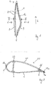
- Fig. 2 shows a cross section of a rotor blade 20 according to the prior art along a line which is approximately the height of in Fig. 1 cross-section line II - II.
- Fig. 1 only one rotor blade half shell 1 drawn during Fig. 2 a cross section of the complete rotor blade 20 shows.
- the two rotor blade half shells 1, 21 each have an associated rotor blade half shell edge 8a, 22a, and they are glued together along their rotor blade half shell edges 8a, 22a.
- the two main straps 2, 23 within the rotor blade 20 are approximately parallel to each other.
- the two main straps 2, 23 are glued together by means of a web 24, which is also manufactured separately in a lamination process, by two adhesive bonds between web sides and inner sides of the belt.
- the web 24 has on its longitudinal sides adhesive lips, which produce a larger contact surface between the main belt 2, 23 and web 24.
- the trailing edge belts 3, 25 are arranged very close to the respective trailing edge edge 8a, 22a and are also arranged in the longitudinal aerodynamic region of the rotor blade 20 closely to the respective rotor blade trailing edge edge 8a, 22a, the two trailing edge belts 3, 25 have to the trailing edge edge 8a, 22a be beveled so that when the two Rotorblattgurschalen 1, 21, the two trailing edge belts 3, 25 do not touch, in particular not touch rather than the two Rotorblattgurschalenhearkantenr selected 8a, 22a and so make a bond impossible or at least hinder.
- the two trailing edge straps 3, 25 in cross-section approximately half-lenticular or slightly curved inward.
- Fig. 3 a known construction of the trailing edge belt 3 is shown.
- approximately equal width, preferably exactly equal width fiber layers 31 are not exactly one above the other, but offset along a width B of the rotor blade 20 and the rotor blade half shell 1, 21 superimposed so that overlap in a middle width along the width B more fiber layers than at longitudinal edges of the trailing edge belts 3, 25, so the further one along the width in the direction of the leading edge 6 and the trailing edge 7, the less fiber layers 31 overlap each other, and thus creates a semi-lenticular shape in cross section.
- the semi-lenticular shape is created after infusion with the resin system by infusing the fiber layers with a resin system.
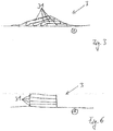
- Fig. 4 shows a rotor blade half shell according to the invention 1.
- the to the Fig.1, 2 . 3 Said can also be transferred to the rotor blade 20 according to the invention except for the arrangement of the trailing edge belt 3. Therefore, the same reference numerals are chosen.
- the rotor blade half shells 1, 21 themselves can in a conventional manufacturing process, for. B. in the infusion process, are manufactured. Likewise, the main straps 2, 23 can be manufactured in a known manner. The position of the two trailing edge belts 3, 25 in the two rotor half shells 1, 21 differs from the prior art Fig.1 and Fig. 2 ,
- the trailing edge belt 3 is according to Fig. 4 no longer guided along the entire longitudinal direction L of the rotor blade half shell 1 closely along the trailing edge edge 8a, but it preferably has a different distance from the trailing edge edge 8a. In the aerodynamic region of the rotor blade, the distance from the rear edge edge 7 is greater than in the area of the root-side end 5.
- Fig. 5 shows a cross section according to the invention of a rotor blade 20 according to the invention along a line which is approximately at the level V - V in FIG. 4 is arranged, in Fig. 4 just one rotor blade half shell 1 is shown while in Fig. 5 a cross section of a complete rotor blade 20 is shown.
- the two trailing edge belts 3, 25 are compared to Fig. 2 further spaced from the trailing edge edges 8a, 22a, in particular, the two trailing edge belts 3, 25 spaced so far from the rotor blade trailing edge 7 that they are rectangular in cross-section, preferably formed exactly rectangular.
- the distance from the rotor blade half shell trailing edge edge 8a, 22a is in each case dimensioned such that when the two rotor blade half shells 1, 21 are folded onto each other, in spite of the cross section rectangular shape of both trailing edge belts 3, 25, the two trailing edge belts 3, 25 do not touch, while, however, the two trailing edge edges 8a, 22a are so close to each other that they can be glued together.
- the two trailing edge belts 3, 25 are connected to a stringer 50 with each other via adhesive bonds.
- Fig. 6 shows the cross section of one of the trailing edge belts 3, 25 according to the invention.
- the layer structure can be selected in a known manner, ie the type of material of the layers and the number of layers can according to the prior art as the structure in Fig. 3 be elected. However, other layer sequences and a different number of layers can also be selected compared with the prior art. However, it is essential to the invention that the individual layers are no longer offset, but are preferably positioned exactly one above the other so that their lateral edges are arranged parallel to one another and perpendicular to the inside of the rotor blade half shell 1. As a result, a rectangular shape of the trailing edge belts 3, 25, which is substantially rectangular in cross section, is formed in contrast to the prior art.
- cross-section rectangular trailing edge belts 3, 25 have compared to the cross-sectionally elliptical belts in a higher buckling stiffness with the same cross-sectional area.
- the trailing edge belts 3, 25 are then critical when the tip end 4 is bent by external forces against the direction of rotation of the rotor in the direction of the trailing edge 7 and the trailing edge 7 is thereby under a compressive load. It has been found that with the same cross-sectional area rectangular trailing edge belts 3, 25 have a higher Beulsteifmaschine than in cross-section semi-elliptical trailing edge belts 3, 25.
- the invention can save material, without security against dents of the trailing edge and the trailing edge of the Reduce rotor blade.
Abstract
Die Erfindung betrifft ein Rotorblatt einer Windenergieanlage mit zwei Rotorblatthalbschalen (1, 21) mit jeweils einem Vorder- und einem Hinterkantenrand (8a, 22a), die entlang der Vorder- und Hinterkantenränder (8a, 22a) miteinander verklebt sind und die jeweils einen Hinterkantengurt (3, 25 aufweisen und jeder der Hinterkantengurte (3, 25) zumindest abschnittsweise in einem Querschnitt entlang seiner Längsausdehnung rechteckig ausgebildet ist.The invention relates to a rotor blade of a wind energy plant with two rotor half shells (1, 21) each having a front and a trailing edge edge (8a, 22a) which are glued together along the front and rear edge edges (8a, 22a) and each having a trailing edge belt ( 3, 25 and each of the trailing edge belts (3, 25) is formed at least in sections in a cross section along its longitudinal extent rectangular.
Description
Die Erfindung betrifft ein Rotorblatt nach dem Oberbegriff des Anspruchs 1 und ein Verfahren zur Fertigung eines Rotorblattes nach dem Oberbegriff des Anspruchs 9.The invention relates to a rotor blade according to the preamble of
Rotorblätter für Windenergieanlagen sind im Stand der Technik natürlich hinlänglich bekannt.Rotor blades for wind turbines are of course well known in the art.
In der
Des Weiteren entspricht es dem Stand der Technik, in Rotorblättern für Windkraftanlagen Gurte aus im Wesentlichen in Richtung der Längsrichtung des Rotorblattes verlaufenden Fasern vorzusehen, die unmittelbar entlang der Hinterkante des Rotorblattes platziert werden. Dabei weisen beide Halbschalen, die Bestandteil des Rotorblattes sind, je einen Hinterkantengurt auf, die dann entsprechend dem Stand der Technik entlang der Hinterkante direkt miteinander verklebt werden.Furthermore, it corresponds to the prior art to provide in rotor blades for wind turbines straps extending substantially in the direction of the longitudinal direction of the rotor blade fibers, which are placed directly along the trailing edge of the rotor blade. In this case, both half-shells, which are part of the rotor blade, each have a trailing edge belt, which are then bonded together according to the prior art along the trailing edge directly.
Nachteilig an den bekannten Rotorblättern ist die Tatsache, dass mehr Material für die Ausbildung des Hinterkantengurtes verwendet werden muss, als für die Erfüllung der Steifigkeitsanforderungen notwendig wäre, da diese dem Stand der Technik entsprechende Konfiguration sehr stark zu einer Beulinstabilität neigt, wenn die Hinterkante des Rotorblattes auf Druck belastet wird. Daher müssen zusätzliche Lagen von Faserhalbzeugen eingebracht werden, um die geforderte Sicherheit gegen Beulen zu erreichen. Da aber der Abstand zwischen der Oberfläche der aerodynamischen Druckseite des Rotorblattes und seiner aerodynamischen Saugseite gering ist, ist auch der Steineranteil, den jede zusätzliche Lage von Faserhalbzeug verursacht, gering. Daher ist die Effektivität zusätzlicher Lagen von Faserhalbzeugen in der Hinterkante zur Erhöhung der Sicherheit gegen Beulinstabilitäten sehr gering, und es wird eine sehr große zusätzliche Anzahl von Lagen von Faserhalbzeugen benötigt, was das Rotorblatt unnötig teuer macht.A disadvantage of the known rotor blades is the fact that more material must be used for the formation of the trailing edge belt, as would be necessary for the fulfillment of the stiffness requirements, since this configuration corresponds to the prior art very much tends to buckling instability when the trailing edge of the rotor blade is loaded on pressure. Therefore, additional layers of semi-finished fiber must be introduced to achieve the required security against dents. But since the distance between the surface of the aerodynamic pressure side of the rotor blade and its aerodynamic suction side is low, and the Steiner share, which causes any additional layer of semi-finished fiber, is low. Therefore, the effectiveness of additional layers of semi-finished fiber products in the trailing edge to increase the security against buckling instabilities very low, and it requires a very large additional number of layers of semi-finished fiber, which makes the rotor blade unnecessarily expensive.
Es ist daher Aufgabe der vorliegenden Erfindung, ein Rotorblatt der eingangs genannten Art dahingehend zu verbessern, dass bei gleicher Sicherheit gegen Beulinstabilität und bei gleichen äußeren Abmessungen des Rotorblattes weniger Material verbraucht wird.It is therefore an object of the present invention to improve a rotor blade of the type mentioned in that with the same security against buckling instability and at the same outer dimensions of the rotor blade less material is consumed.
Es ist des Weiteren Aufgabe der vorliegenden Erfindung, ein Verfahren zur Verfügung zu stellen, mit dessen Hilfe ein erfindungsgemäßes Rotorblatt gefertigt werden kann.It is a further object of the present invention to provide a method by means of which a rotor blade according to the invention can be manufactured.
Hinsichtlich des Rotorblattes wird die Aufgabe durch ein eingangs genanntes Rotorblatt mit den Merkmalen des Anspruchs 1 gelöst.With regard to the rotor blade, the object is achieved by an initially mentioned rotor blade having the features of
Das erfindungsgemäße Rotorblatt weist zwei jeweils in einem Laminierverfahren hergestellte Rotorblatthalbschalen auf, die jeweils einen die Rotorblatthalbschalen fast ganz umlaufenden Rand aufweisen, entlang dem die beiden Rotorblatthalbschalen miteinander verklebt werden. Lediglich an einer Wurzel des Rotorblattes verbleibt eine Öffnung, über die das Rotorblatt mit einem Anschluss an einer Rotornabe befestigt werden kann. In jeder der beiden Halbschalen ist jeweils wenigstens ein Hinterkantengurt, vorzugsweise jeweils genau ein Hinterkantengurt angeordnet. Erfindungsgemäß verlaufen die Hinterkantengurte entlang des jeweiligen Hinterkantenrandes der Rotorblatthalbschale in einer Längsrichtung, und sie sind in einem Querschnitt quer, vorzugsweise senkrecht zu ihrer Längsrichtung zumindest entlang eines Abschnitts in Längsrichtung rechteckig ausgebildet. Unter rechteckig wird hier auch eine im Wesentlichen rechteckige Querschnittsform verstanden. Die Ecken können leicht abgerundet oder der Querschnitt trapezförmig oder rhombisch ausgebildet sein. Vorzugsweise ist der Querschnitt abschnittsweise rechteckig, vorzugsweise exakt rechteckig. Es kann auch ein quadratischer Querschnitt vorgesehen sein. Vorzugsweise ist der rechteckige Querschnitt so ausgebildet, dass der Hinterkantengurt zumindest entlang der überwiegenden Ausdehnung entlang seiner Breite eine in den Rotorblattinnenraum weisende gerade Innenfläche aufweist und eine Höhe des Rotorblatthinterkantengurtes entlang dieser Breite gleich ist. Der Rotorblatthinterkantengurt kann an den Längskanten jedoch abgeschrägt, abgerundet oder abgeflacht auf die Rotorblattinnenwandung verlaufend ausgebildet sein, sodass keine scharfen oder empfindlichen Kanten freiliegen. Auch die vorbezeichneten glatten Querschnitte werden hier noch als rechteckig bezeichnet, zumindest solange die gerade Innenfläche wenigstens die halbe Breite ausmacht.The rotor blade according to the invention has two rotor blade half shells, each produced in a laminating process, which each have an edge that almost completely surrounds the rotor blade half shells, along which the two rotor blade half shells are glued together. Only at one root of the rotor blade remains an opening through which the rotor blade can be fastened with a connection to a rotor hub. In each of the two half-shells, at least one trailing edge belt is arranged, preferably in each case exactly one trailing edge belt. According to the invention, the trailing edge belts run along the respective trailing edge edge of the rotor blade half shell in a longitudinal direction, and they are rectangular in cross section, preferably perpendicular to their longitudinal direction, at least along a section in the longitudinal direction. Under rectangular is understood here also a substantially rectangular cross-sectional shape. The corners may be slightly rounded or the cross section may be trapezoidal or rhombic. Preferably, the cross section is rectangular in sections, preferably exactly rectangular. It may also be provided a square cross-section. Preferably, the rectangular cross-section is formed such that the trailing edge belt has a straight inside surface facing the rotor blade interior along its width along at least the major extent thereof and a height of the rotor blade trailing edge belt is equal along this width. However, the rotor blade trailing edge belt may be chamfered at the longitudinal edges, rounded or flattened running on the rotor blade inner wall, so that no sharp or sensitive edges are exposed. The aforementioned smooth cross sections are still referred to here as rectangular, at least as long as the straight inner surface is at least half the width.
Vorzugsweise liegen sich zwei Hinterkantengurte gegenüber, und jeder der beiden sich gegenüberliegenden Hinterkantengurte weist jeweils entlang eines Abschnitts, der sich in der Längsrichtung erstreckt, einen quer, vorzugsweise senkrecht zur Längsrichtung rechteckigen Querschnitt auf. Unter der Längsrichtung ist hier eine Längsrichtung des Hinterkantengurtes entlang des jeweiligen Abschnitts zu verstehen, die entlang des Hinterkantengurtes veränderlich sein kann und auch etwas von der Längsrichtung des Rotorblattes abweichen kann.Preferably, two trailing edge straps face each other and each of the two opposite trailing edge straps has a cross section which is transversely, preferably perpendicular to the longitudinal direction, along each section extending in the longitudinal direction. The longitudinal direction here means a longitudinal direction of the trailing edge belt along the respective section, which may be variable along the trailing edge belt and may also deviate slightly from the longitudinal direction of the rotor blade.
Die beiden Hinterkantengurte liegen sich gegenüber, wenn sie mit ihren breiten Innenseiten einander gegenüberliegen.The two trailing edge straps face each other when facing each other with their broad insides.
Vorzugsweise ist der Hinterkantengurt in dem Abschnitt, in dem der wenigstens eine Hinterkantengurt im Querschnitt rechteckig ausgeformt ist, weiter von dem ihm zugeordneten Hinterkantenrand entfernt als in anderen Abschnitten.Preferably, in the portion where the at least one trailing edge belt is rectangular in cross-section, the trailing edge belt is further away from its associated trailing edge edge than in other portions.
Günstigerweise weist eine Hinterkante des Rotorblattes in dem Abschnitt höchstens eine erste Dicke auf, und der Hinterkantengurt ist entlang des Abschnittes überall weiter von dem Hinterkantenrand beabstandet als in einem anderen Abschnitt, in dem das Rotorblatt eine größere als die erste Dicke aufweist. Unter der Dicke wird hier der Abstand zweier Punkte der Rotorblattaußenhaut senkrecht zur Rotorblattsehne oder zur Skelettlinie verstanden. Unter dem Abschnitt ist hier der Bereich zu verstehen, in dem der Hinterkantengurt vorgesehen ist. Der Hinterkantengurt ist somit dort weiter von dem ihm zugeordneten Hinterkantenrand beabstandet wo das Rotorblatt eine erste Dicke aufweist, die aber gering ist, zumindest geringer als in anderen Abschnitten, in denen der Hinterkantengurt dichter an der Hinterkante verläuft.Conveniently, a trailing edge of the rotor blade has at most a first thickness in the portion, and the trailing edge belt is spaced along the portion anywhere farther from the trailing edge edge than in another portion where the rotor blade is greater than the first thickness. Under the thickness is understood here the distance between two points of the rotor blade outer skin perpendicular to the rotor blade chord or to the skeleton line. Under the section is here to understand the area in which the trailing edge belt is provided. The trailing edge belt is thus further spaced from its associated rear edge edge where the rotor blade has a first thickness, but which is low, at least less than in other sections where the trailing edge belt runs closer to the trailing edge.
Vorzugsweise ist jeder der Hinterkantengurte von den ihnen zugeordneten Hinterkantenrändern so weit beabstandet ist, dass ein Mindestabstand zwischen den beiden Rotorblatthalbschalen in dem Bereich, in dem sich die Hinterkantengurte befinden, wenigstens 3 mm beträgt. Unter dem Abstand wird hier der lichte Abstand zweier Punkte der Rotorblattinnenhaut senkrecht zur Rotorblattsehne oder zur Skelettlinie verstanden.Preferably, each of the trailing edge straps is spaced from its associated trailing edge margins so that a minimum distance between the two rotor half shells in the region where the trailing edge straps are located is at least 3 mm. Under the distance here the clear distance between two points of the rotor blade inner skin perpendicular to the rotor blade chord or to the skeleton line understood.
Erfindungsgemäß wird der Hinterkantengurt also mindestens abschnittsweise von der Hinterkante in Richtung Profilnase verschoben, um so ein höheres Flächenträgheitsmoment der Hinterkantengurte bezüglich der Profilsehne zu realisieren, wenn die Querschnittfläche des Hinterkantengurtes unverändert bleibt zu einer Ausführung entsprechend dem Stand der Technik. Gleichzeitig erweist es sich bei einer erfindungsgemäßen Anordnung der Hinterkantengurte im Rotorblatt als vorteilhaft für den Fertigungsablauf, den Querschnitt des Gurtes im Wesentlichen rechteckig zu gestalten.According to the Hinterkantengurt is thus at least partially shifted from the trailing edge in the direction of profile nose, so a higher area moment of inertia the trailing edge straps with respect to the chord, when the cross-sectional area of the trailing edge belt remains unchanged from a prior art embodiment. At the same time it proves to be advantageous in an inventive arrangement of the trailing edge belts in the rotor blade as advantageous for the manufacturing process, to make the cross section of the belt substantially rectangular.
Günstigerweise verläuft der Hinterkantengurt entlang der Hinterkante. Er kann also verschiedene Abstände von der Hinterkante entlang der Längsrichtung aufweisen. Günstigerweise ist der Hinterkantengurt dort im Querschnitt rechteckig ausgebildet, wo die die Hinterkante eine geringe Dicke aufweist. Er kann in diesen Abschnitten weiter von der Hinterkante beabstandet sein als in anderen Abschnitten.Conveniently, the trailing edge belt runs along the trailing edge. It can thus have different distances from the trailing edge along the longitudinal direction. Conveniently, the trailing edge belt is rectangular in cross section where the trailing edge has a small thickness. It may be further spaced from the trailing edge in these sections than in other sections.
Zusätzlich wird erfindungsgemäß eine Verbindung zwischen den gegenüberliegenden Hinterkantengurte durch einen Steg oder Stringer vorgesehen. So ergibt sich eine Anordnung, die ein deutlich verbessertes Verhältnis von eingesetzter Masse zu erzielter Beulsicherheit aufweist.In addition, a connection between the opposite trailing edge straps is provided by a web or stringer according to the invention. This results in an arrangement which has a significantly improved ratio of inserted mass to achieved Beulsicherheit.
Erfindungsgemäß weist der Hinterkantengurt einen signifikant kleineren Querschnitt auf als der Hauptgurt in der gleichen Entfernung zur Blattwurzel.According to the invention, the trailing edge belt has a significantly smaller cross section than the main belt at the same distance from the blade root.
Es hat sich gezeigt, dass Gurte mit einem rechteckigen Querschnitt leichter zu fertigen sind als andere Querschnittsformen. Deshalb sind die Hinterkantengurte in einer bevorzugten Ausführungsform entlang ihrer Längsausdehnung, vorzugsweise entlang ihrer gesamten Längsausdehnung, im Querschnitt rechteckig ausgebildet, wobei allerdings die Querschnittsfläche, insbesondere die Höhe des Rechteckes variieren kann.It has been found that straps with a rectangular cross-section are easier to manufacture than other cross-sectional shapes. Therefore, in a preferred embodiment, the trailing edge straps are rectangular in cross-section along their longitudinal extent, preferably along their entire longitudinal extent, although the cross-sectional area, in particular the height of the rectangle, may vary.
Erfindungsgemäß sind die im Querschnitt rechteckigen Hinterkantengurte jedoch nicht mehr, wie im Stand der Technik bekannt, überall unmittelbar entlang der Rotorblatthinterkante verlegt, sondern sie weisen einen variierenden und vorzugsweise abschnittsweise größeren Abstand von der Rotorblatthinterkante auf. Insbesondere in im Querschnitt engen Bereichen der Hinterkante sind die Rotorblatthinterkantengurte weiter von dem Rotorblatthinterkantenrand beabstandet als beispielsweise im großräumigeren Wurzelbereich des Rotorblattes. Die Festlegung des Abstandes zwischen Hinterkantengurt und Hinterkante des Rotorblattes ist eine Optimierungsaufgabe, bei der die Querschnittfläche des Hinterkantengurtes und sein Abstand zur Hinterkante des Rotorblattes, welcher den Abstand der Hinterkantengurte zueinander über die Profilform festlegt, so gewählt werden müssen, dass sich ein Minimum des Verhältnisses aus eingesetzter Masse zu erzielter Beulsicherheit ergibt.However, according to the invention, the trailing edge belts, which are rectangular in cross section, are no longer laid everywhere along the rotor blade trailing edge, as is known in the prior art, but instead have a varying distance, preferably in sections, from the rotor blade trailing edge. Particularly in regions of the trailing edge which are narrow in cross-section, the rotor blade trailing edge belts are spaced further from the rotor blade trailing edge edge than, for example, in the larger-area root region of the rotor blade. The determination of the distance between Hinterkantengurt and trailing edge of the rotor blade is an optimization task, in which the cross-sectional area of the trailing edge belt and its distance from the trailing edge of the rotor blade, which Defines the distance of the trailing edge belts to each other on the profile shape, must be chosen so that there is a minimum of the ratio of mass used to achieved Beulsicherheit.
In dem mit einer geringeren Höhe des Rotorblattinnenraumes versehenen aerodynamischen Abschnitt des Rotorblattes sollte dieser größere Abstand von der Hinterkante des Rotorblattes zur Verfügung gestellt werden, damit sich die Hinterkantengurte beim Zusammenklappen der Rotorblatthalbschalen während der Fertigung nicht berühren und immer noch eine Klebverbindung zwischen den beiden Rotorblatthalbschalenrändern möglich ist. Die beiden Hinterkantengurte dürfen nicht vor den Rotorblatthalbschalenrändern aufeinanderstoßen und ein vollständiges Zusammenklappen der Rotorblatthalbschalen verhindern. Günstigerweise sind die beiden Hinterkantengurte von ihren Hinterkantenrändern so weit beabstandet, dass ein Mindestabstand von ca. 3,0 mm und ein Maximalabstand von ca. 20 mm - 50 mm zwischen den einander zugewandten Innenseiten der beiden Hinterkantengurten in Profildickenrichtung des Rotorblattes beträgt, sich die beiden Hinterkantengurte also während des Fertigungsverfahrens beim Zusammenklappen der Rotorblätter nicht berühren und sogar einen lichten Abstand voneinander aufweisen, der über einen Steg, vorzugsweise über einen Stringer überbrückt wird.In the provided with a lower height of the rotor blade interior aerodynamic portion of the rotor blade, this greater distance should be provided by the trailing edge of the rotor blade, so that the trailing edge straps do not touch during the folding of the rotor blade half shells during manufacture and still possible an adhesive bond between the two Rotorblatthalbbschalenrändern is. The two trailing edge belts must not collide in front of the rotor blade half shell edges and prevent complete collapse of the rotor blade half shells. Conveniently, the two trailing edge belts are spaced so far from their trailing edge edges that a minimum distance of about 3.0 mm and a maximum distance of about 20 mm - 50 mm between the facing inner sides of the two trailing edge belts in the profile thickness direction of the rotor blade, the two Hinterkantengurte so during the manufacturing process when folding the rotor blades do not touch and even have a clearance from each other, which is bridged over a web, preferably via a stringer.
Aufgrund des Höchstabstandes der beiden Hinterkantengurte von zwischen vorzugsweise 2 cm bis 5 cm ist es sinnvoll, den Hinterkantengurt der saugseitigen mit dem Hinterkantengurt der druckseitigen Rotorblatthalbschale durch einen Stringer anstatt eines Steges zu verbinden.Due to the maximum distance of the two trailing edge belts of preferably between 2 cm to 5 cm, it makes sense to connect the trailing edge belt of the suction side with the trailing edge belt of the pressure side rotor blade half shell by a stringer instead of a web.
Bei einem Stringer handelt es sich vorzugsweise ebenfalls um ein Faserverbundstoffbauteil, das im Querschnitt jedoch nicht wie ein Steg rechteckförmig mit einer um das Vielfache größeren Höhe als einer Breite ausgebildet ist, sondern bei dem die Höhe des Bauteils geringer ist als die Breite des Bauteils ist. So ist die Höhe des Stringers beispielsweise 2 cm bis 5 cm, während die Breite des Stringers etwa 20 cm bis 30 cm beträgt. Bauhöhe und - breite variieren aber entlang der Längsausdehnung des Rotorblattes.A stringer is preferably likewise a fiber composite component which, however, is not rectangular in cross-section like a web with a height greater by a multiple than a width, but in which the height of the component is less than the width of the component. For example, the height of the stringer is 2 cm to 5 cm, while the width of the stringer is about 20 cm to 30 cm. Overall height and width vary along the longitudinal extent of the rotor blade.
In einer besonders vorteilhaften Ausführungsform der Erfindung weist der Stringer einen trapezförmigen Querschnitt auf, wodurch er gut bei der Herstellung der entsprechenden Blattschale, z. B. bei der Infusion, integriert werden kann.In a particularly advantageous embodiment of the invention, the stringer has a trapezoidal cross section, whereby it is well in the production of the corresponding leaf shell, z. B. during infusion, can be integrated.
Die beiden Hinterkantengurte der beiden Rotorblatthalbschalen weisen vorzugsweise eine Breite von 20 cm bis 30 cm auf. Die Breite der Hinterkantengurte ist über die gesamte Längsausdehnung des Hinterkantengurtes im Wesentlichen gleich, vorzugsweise exakt gleich. Dadurch ist eine einfache Herstellung des Hinterkantengurtes möglich.The two trailing edge belts of the two rotor half shells preferably have a width of 20 cm to 30 cm. The width of the trailing edge belts is substantially the same over the entire longitudinal extent of the trailing edge belt, preferably exactly the same. As a result, a simple production of the trailing edge belt is possible.
Zweckmäßigerweise ist der Hinterkantengurt aus mehreren über- und/oder nebeneinander gelegten Schichten eines Faserhalbzeugs gebildet. Bei dem Faserhalbzeug kann es sich um ein Gebilde aus Natur-, Kunststoff-, Glas- oder Kohlefasern oder Ähnliches handeln, das mit einem Harz getränkt wird und dann aushärtet. Die erfindungsgemäße Ausbildung des Rotorblattes soll aber auch andere Formen von Faserhalbzeugen wie Prepregs und Pultrudate umfassenAdvantageously, the trailing edge belt is formed from a plurality of superimposed and / or juxtaposed layers of a semi-finished fiber product. The semi-finished fiber may be a structure of natural, plastic, glass or carbon fibers or the like, which is impregnated with a resin and then cured. The inventive design of the rotor blade but should also include other forms of semi-finished fiber products such as prepregs and Pultrudate
Die Anzahl der übereinandergeschichteten Schichten des Hinterkantengurtes wird der Anforderung an Festigkeit und Beulsicherheit im jeweiligen Rotorblattabschnitt angepasst.The number of layered layers of the trailing edge belt is adapted to the requirement for strength and buckling safety in the respective rotor blade section.
Vorzugsweise weisen die Hinterkantengurte eine Höhe von weniger als 1 cm an den wurzel- bzw. tipseitigen Enden und bis zu bis 7 - 10 cm an ihrer dicksten Stelle auf.Preferably, the trailing edge belts have a height of less than 1 cm at the root ends and up to 7 - 10 cm at their thickest point.
Hinsichtlich des Verfahrens wird die Aufgabe durch ein Verfahren mit den Merkmalen des Anspruchs 11 gelöst. Das Verfahren eignet sich insbesondere zur Fertigung eines der oben genannten Rotorblätter.With regard to the method, the object is achieved by a method having the features of claim 11. The method is particularly suitable for the production of one of the above-mentioned rotor blades.
Rotorblätter werden vorzugsweise aus separat gefertigten Bauteilen, wie Rotorblatthalbschalen, Stegen, Stringer und Gurten, zusammengesetzt. Die separaten Bauteile werden in diesem Falle in für sie individuell bestimmten Herstellungsformen gefertigt. In die Herstellungsformen werden zunächst mehrere Schichten, beispielsweise faserhaltige Schichten aus Glas- und/oder Kohlenstofffaser und/oder Kunststoffen und/oder auch Naturstoffen sowie Schäume und Balsa usw. übereinander- und nebeneinandergelegt. Die so angeordneten Schichten bilden ein vorzugsweise trockenes Halbzeug aus. Das Halbzeug wird in Verfahren wie beispielsweise dem resin injection moulding (RIM-Verfahren) oder dem resin transfer moulding (RTM-Verfahren) mit einem Harzsystem getränkt. Nach dem Aushärten des Harzsystems werden die Bauteile zusammengeklebt und das Rotorblatt endgefertigt. Es sind aber auch Fertigungsverfahren wie der Einsatz von Prepregs und Pultrudaten in der erfindungsgemäßen Herstellung des Rotorblattes eingeschlossen. Insbesondere hinsichtlich der Herstellung der Gurte ist es bevorzugt vorgesehen, dass die Gurte bereits integraler Bestandteil der Rotorblatthalbschalen sind, also während des Herstellungsverfahrens der Rotorblatthalbschalen integral mitgefertigt werden. Sie können aber auch nachträglich auf die Innenseiten der Rotorblatthalbschalen aufgeklebt werden oder als vorgefertigte Bauteile bei der Herstellung der Rotorblatthalbschalen eingebracht werden.Rotor blades are preferably composed of separately manufactured components, such as rotor blade half shells, webs, stringers and straps. The separate components are manufactured in this case in individually determined for their production forms. In the production forms, first several layers, such as fiber-containing layers of glass and / or carbon fiber and / or plastics and / or natural materials and foams and balsa, etc. superimposed and juxtaposed. The layers thus arranged form a preferably dry semifinished product. The semifinished product is impregnated with a resin system in processes such as resin injection molding (RIM process) or resin transfer molding (RTM process). After the curing of the resin system, the components are glued together and the rotor blade finished. However, manufacturing processes such as the use of prepregs and pultrusions in the production of the rotor blade according to the invention are also included. In particular, with regard to the production of the straps, it is preferably provided that the straps are already an integral part of the rotor blade half shells, that are integrally mitgefertigt during the manufacturing process of the rotor blade half shells. But they can also be subsequently glued to the inner sides of the rotor blade half shells or introduced as prefabricated components in the manufacture of the rotor blade half shells.
Insbesondere die Hinterkantengurte verlaufen zweckmäßigerweise möglichst dicht an der Rotorblatthinterkante, um die Steifigkeit in Schwenkrichtung besonders stark zu erhöhen. Dabei entsteht jedoch das Problem, dass insbesondere im aerodynamischen Bereich des Rotorblattes entlang der Rotorblatthinterkante nur sehr wenig freier, insbesondere nicht sehr hoher Innenraum im Rotorblatt zur Verfügung steht. Insbesondere führt dieses dazu, dass die Rotorblatthinterkantengurte gemäß dem Stand der Technik zumindest entlang ihrer zur Rotorblatthinterkante weisenden Längsseite zur Hinterkante hin abgeflacht oder abgerundet sind, damit sie beim Zusammenklappen und Zusammenkleben der beiden Rotorblatthalbschalen nicht aufeinanderstoßen und ein vollständiges Verkleben der Rotorblatthalbschalen verhindern. Dadurch ergibt sich beim Stand der Technik eine sehr geringe, oft zu geringe Sicherheit gegen Beulen, sodass zusätzliches Material in den Hinterkantengurten vorgesehen werden muss, was das Rotorblatt verteuert.In particular, the trailing edge belts suitably run as close as possible to the rotor blade trailing edge in order to increase the rigidity in the pivoting direction particularly strong. However, there arises the problem that only in the aerodynamic region of the rotor blade along the rotor blade trailing edge very little free, especially not very high interior space is available in the rotor blade. In particular, this leads to the fact that the rotor blade trailing edge belts according to the prior art are flattened or rounded at least along their longitudinal side facing the rotor blade trailing edge to the trailing edge, so that they do not collide when folding and gluing the two rotor half shells and prevent complete sticking of the rotor blade half shells. This results in the prior art, a very low, often too low security against dents, so that additional material must be provided in the trailing edge belts, which makes the rotor blade more expensive.
Üblicherweise und auch erfindungsgemäß werden die Rotorblatthalbschalen in separaten Formhalbschalen gefertigt, die nebeneinander angeordnet sind und über eine gelenkige Verbindung aufeinandergeschwenkt werden können. Dieser Schwenkmechanismus ermöglicht es, die fast vollständig umlaufenden Ränder der beiden Rotorblatthalbschalen positionsgenau übereinander zu positionieren und nach Auftrag einer Klebmittelschicht entlang der beiden oder zumindest einer der beiden Ränder miteinander zu verkleben.Usually and also according to the invention, the rotor blade half-shells are manufactured in separate half-shells which are arranged next to one another and can be pivoted towards one another via an articulated connection. This pivoting mechanism makes it possible to position the almost completely circumferential edges of the two rotor half-shells exactly one above the other and to glue them together after application of an adhesive layer along the two or at least one of the two edges.
Vor dem Zusammenklappen der beiden Formhalbschalen werden zweckmäßigerweise auch die Stege, Stringer und Gurte in die Rotorblatthalbschalen eingeklebt.Before folding the two half-shells, the webs, stringer and straps are expediently glued into the rotor blade half-shells.
Das erfindungsgemäße Verfahren macht von der Idee Gebrauch, die Hinterkantengurte durch vorzugsweise exaktes Übereinanderanordnen von Schichten, d. h. Faserlagen aus unterschiedlichsten Materialien zu fertigen, wobei das aus den übereinander angeordneten Schichten gebildete Halbzeug z. B. mit einem Harzsystem infundiert wird, das anschließend aushärtet. Es sind auch andere Herstellungsverfahren, wie z. B. der Einsatz von Prepregs oder Pultrudaten denkbar. Es entsteht ein rechteckförmiger Querschnitt des Hinterkantengurtes, wobei der Hinterkantengurt natürlich der aerodynamischen Form der Rotorblattinnenwandung entlang der Längsausdehnung angepasst sein muss, also insbesondere in Längsrichtung nicht exakt gerade verläuft, sondern bogenförmig der Hinterkante und der Oberfläche des Rotorblattes folgt, damit er überall in die Blattschalenstruktur integriert werden kann.The inventive method makes use of the idea to produce the trailing edge belts by preferably exactly superposing layers, ie fiber layers made of different materials, wherein the semifinished product formed from the superimposed layers z. B. is infused with a resin system, which then hardens. There are also other manufacturing methods, such as. As the use of prepregs or Pultrudaten conceivable. The result is a rectangular cross-section of the trailing edge belt, the trailing edge belt of course must be adapted to the aerodynamic shape of the rotor blade inner wall along the longitudinal extent, ie not exactly straight in the longitudinal direction, but arcuately the trailing edge and the surface of the rotor blade follows, so that he everywhere in the leaf shell structure can be integrated.
Die Hinterkantengurte weisen aber wenigstens im aerodynamischen Abschnitt einen Abstand vom Hinterkantenrand auf. Unter einem Abstand wir hier ein Abstand eines dem Hinterkantenrand benachbarten Längsrandes des Hinterkantengurtes von dem Hinterkantenrand verstanden der nicht Null sondern vorzugsweise einige Zentimeter beträgt. Es werden so viele Schichten übereinandergelegt, dass der Hinterkantengurt eine Dicke von 1 cm bis 10 cm vorzugsweise bis zu 7 - 8 cm nach der Harzinfusion aufweist.The trailing edge belts, however, at least in the aerodynamic section at a distance from the trailing edge edge. Here, a distance is understood to be a distance of a longitudinal edge of the trailing edge belt adjacent to the trailing edge edge from the trailing edge edge which is not zero but preferably a few centimeters. There are so many layers superimposed that the trailing edge belt has a thickness of 1 cm to 10 cm, preferably up to 7 - 8 cm after the resin infusion.
Der Rotorblatthinterkantengurt kann einstückig oder mehrstückig ausgebildet sein, wobei die einzelnen Stücke dann aneinander in die Rotorblatthalbschalen eingeklebt und miteinander verbunden werden.The rotor blade trailing edge belt can be formed in one piece or in several pieces, with the individual pieces then being glued to one another in the rotor blade half shells and connected to one another.
Die einzelnen Faserlagen des Rotorblatthinterkantengurtes weisen vorzugsweise eine gleiche Breite auf, sodass die Längskanten der Gewebelagen exakt übereinander positioniert werden, wobei Entformungsschrägen vorgesehen werden können.The individual fiber layers of the rotor blade trailing edge belt preferably have a same width, so that the longitudinal edges of the fabric layers are positioned exactly one above the other, wherein Entformungsschrägen can be provided.
Es hat sich gezeigt, dass bei einer gleichen Querschnittsfläche des Rotorblatthinterkantengurtes diese rechteckförmige Form eine höhere Beulsteifigkeit auch bei einem größeren Abstand von der Rotorblatthinterkante aufweist als herkömmliche, exakt entlang der Rotorblatthinterkante verlaufende Gurte mit abgeschrägten oder abgerundeten Längskanten.It has been found that with a same cross-sectional area of the rotor blade trailing edge belt, this rectangular shape has a higher buckling rigidity even at a greater distance from the rotor blade trailing edge than conventional straps running exactly along the rotor blade trailing edge with bevelled or rounded longitudinal edges.
Besonders bevorzugt werden die Innenseiten der sich im Rotorblattinnenraum gegenüberliegenden Hinterkantengurte mit Stringern verbunden. Stringer sind aufgrund ihrer gegenüber Stegen größeren Breite und dem vorzugsweise trapezförmigen Querschnitt einfacher beim Bau der Blattschale zu realisieren als Stege.Particularly preferably, the inner sides of the rear edge girths located opposite the rotor blade interior are connected to stringers. Stringers are due to their opposite webs larger width and preferably trapezoidal cross section easier to realize the construction of the leaf shell than webs.
Die Erfindung wird anhand eines Ausführungsbeispiels in sechs Figuren beschrieben, dabei zeigen:
- Fig. 1
- eine Innenansicht eines herkömmlichen Rotorblattes mit einem Hauptgurt und einem Hinterkantengurt,
- Fig. 2
- eine Schnittansicht eines herkömmlichen Rotorblattes entlang einer Linie II - II der
Fig. 1 , - Fig. 3
- eine Schnittansicht eines Aufbaus eines Hinterkantengurtes gemäß dem Stand der Technik,
- Fig. 4
- eine Innenansicht einer erfindungsgemäßen Rotorblatthalbschale mit einem Hauptgurt und einem erfindungsgemäßen Hinterkantengurt,
- Fig. 5
- eine Schnittansicht eines erfindungsgemäßen Rotorblattes entlang einer Linie V - V in
Fig. 4 , - Fig. 6
- eine Schnittansicht des Aufbaus eines erfindungsgemäßen Hinterkantengurtes.
- Fig. 1
- an interior view of a conventional rotor blade with a main belt and a trailing edge belt,
- Fig. 2
- a sectional view of a conventional rotor blade along a line II - II of
Fig. 1 . - Fig. 3
- FIG. 4 is a sectional view of a structure of a trailing edge belt according to the prior art; FIG.
- Fig. 4
- an interior view of a rotor blade half shell according to the invention with a main belt and a rear edge belt according to the invention,
- Fig. 5
- a sectional view of a rotor blade according to the invention along a line V - V in
Fig. 4 . - Fig. 6
- a sectional view of the structure of a Hinterkantengurtes invention.
In
Rotorblätter werden vorzugsweise aus separat gefertigten Bauteilen wie Rotorblatthalbschalen 1, Gurten, Stegen oder Stringern zusammengesetzt. Die separaten Bauteile werden in für sie individuell bestimmten Herstellungsformen gefertigt. In die Herstellungsformen werden zunächst mehrere Schichten, beispielsweise faserhaltige Lagen, Schäume, Balsa usw. übereinander- und/oder nebeneinandergelegt. Die so angeordneten Schichten bilden ein vorzugsweise trockenes Halbzeug aus. Das Halbzeug liegt auf einer Innenseite einer Herstellungsform und wird an der der Herstellungsform abgewandten Seite mit einer Vakuumfolie abgeklebt. Die Herstellungsform bzw. die Vakuumfolie weisen eine Mehrzahl an Eintrittsöffnungen und Austrittsöffnungen auf. Das Halbzeug wird in Verfahren, wie beispielsweise dem RIM-Verfahren (resin injection moulding) oder dem RTM-Verfahren (resin transfer moulding), mit einem Harzsystem getränkt. Dazu wird das Halbzeug unter der Vakuumfolie, d. h. zwischen Innenwandung der Herstellungsform und der Vakuumfolie unter Unterdruck gesetzt, indem durch die Austrittsöffnungen Luft abgesaugt wird. Auch durch den Unterdruck wird das flüssige bzw. zähflüssige Harzsystem in das Halbzeug eingesaugt und tränkt das Halbzeug vollständig. Das Verfahren wird so lange durchgeführt, bis auch aus den Austrittsöffnungen das Harzsystem entweicht. Es können aber auch Prepregs und/oder Pultrudate eingesetzt werden.Rotor blades are preferably composed of separately manufactured components such as rotor
Gemäß dem Stand der Technik werden die Rotorblatthalbschalen 1 einzeln und jeweils in einem Stück gefertigt. Moderne Rotorblätter weisen Längen zwischen 40 m und 60 m und bis zu 75 m und sogar mehr auf. Zu ihrer Fertigung können Fertigungsformen mit entsprechenden Längen bis zu 70 m, 75 m oder sogar noch längere Fertigungsformen vorgesehen sein.According to the prior art, the rotor
Nach dem Aushärten der Rotorblatthalbschalen 1 werden auf die Innenseite der beiden Rotorblatthalbschalen jeweils ein Hauptgurt 2 und ein Hinterkantengurt 3 geklebt. In
Jede der Rotorblatthalbschalen 1 weist ein tipseitiges Ende 4 und ein wurzelseitiges Ende 5 auf sowie eine Vorder- 6 und eine Hinterkante 7. Die entsprechende Nomenklatur gilt auch für das aus zwei Rotorblattschalen zusammengesetzte Rotorblatt.After hardening of the rotor
Each of the rotor
Die Rotorblatthalbschale 1 fast ganz umlaufend ist ein Rotorblatthalbschalenrand 8 vorgesehen, der eine Breite von vorzugsweise 3 bis 25 cm aufweist. Der Rand 8 verläuft entlang der Rotorblattvorderkante 6 um das tipseitige Ende 4 der Rotorblatthalbschale 1 herum und entlang der gesamten Rotorblatthinterkante 7 Die beiden Rotorblatthalbschalen 1 weisen jeweils den Rand 8 auf, und die Rotorblattschalen 1 werden entlang ihrer beiden Ränder 8 miteinander verklebt. Die Breite des Randes 8 kann bereichsweise variieren, wobei die Übergänge dann vorzugsweise kontinuierlich ausgeführt sind. Dazu sind die Herstellungsformen nebeneinander angeordnet, und eine klappbare Formhalbschale ist über eine positionsfeste Formhalbschale schwenkbar, so dass nach Fertigung der beiden Rotorblatthalbschalen in den beiden Formhalbschalen und deren Aushärtung sowie gegebenenfalls dem Einkleben weiterer Bauteile wie Gurte und Stege die klappbare Formhalbschale über die positionsfeste Form geklappt werden kann.The rotor blade
Es ist auch denkbar, dass beide Formhalbschalen gleichzeitig oder nacheinander klappbar sind und aufeinander zugeklappt werden.It is also conceivable that both half-molds are simultaneously or successively hinged and collapsed towards each other.
Auf die in der positionsfesten Formhalbschale gefertigte Rotorblatthalbschale ist entlang des gesamten Rotorblatthalbschalenrandes 8 ein Klebmittel aufgebracht. Die beiden Rotorblatthalbschalen 1 werden entlang ihrer beiden Ränder 8 mit Hilfe des Klebmittels verklebt. Zum Zusammendrücken der beiden Formhalbschalen können Klemmverschlüsse an den Formhalbschalen vorgesehen sein, die einen hinreichenden Druck zwischen den beiden Rotorblatthalbschalen 1 und damit auf die Klebmasse erzeugen.An adhesive is applied along the entire rotor blade
Entlang der Linie der größten Profildicke ist der Hauptgurt 2 verlegt. Der Hauptgurt 2 kann separat gefertigt werden oder während des Herstellungsprozesses der Rotorblatthalbschale 1 auf der Innenseite der Rotorblatthalbschale 1 integral mitausgebildet werden.Along the line of the largest profile thickness of the
Der Hauptgurt 2 und der Hinterkantengurt 3 weisen ebenfalls in eine Längsrichtung L verlaufende Faserlagen auf, wobei die Faserlagen der Gurte 2, 3, aber auch der Rotorblatthalbschalen 1 oder der Stege Glasfasern, Kohlefasern, kunststoffhaltigen Fasern, Naturfasern, aber auch andere Faserarten aufweisen können. Die einzelnen Faserlagen können jeweils einteilig ausgebildet sein. Es kann bei langen Gurten 2, 3 aber auch zweckmäßig sein, die Gurte 2, 3 entlang der Längsrichtung L stückweise zu fertigen und erst in der Rotorblatthalbschale 1 zusammenzusetzen. Entsprechendes gilt auch für die anderen Bauteile.The
Die Gurte 2, 3 werden ebenfalls in einem Vakuuminfusionsverfahren mit Harz getränkt ausgehärtet und dann auf die Innenseite der Rotorblatthalbschale 1 aufgeklebt oder während des Fertigungsverfahrens der Rotorblatthalbschale 1 integral mitausgeformt. Es ist erfindungsgemäß aber auch möglich, die Gurte 2, 3 vorzufertigen und dann während des Baus der Halbschale zu integrieren, in dem sie z. B. während der Infusion mit den anderen Materialien der Rotorblatthalbschale verbunden werden. Der Hauptgurt 2 dient dazu, die Biegesteifigkeit des Rotorblattes in Schlagrichtung zu erhöhen.The
Die bisherigen Erörterungen betreffen nicht nur die Rohrblätter gemäß dem Stand der Technik, sondern auch die erfindungsgemäßen Rotorblätter.The discussions so far concern not only the tube sheets according to the prior art, but also the rotor blades according to the invention.
Zusätzlich ist gemäß dem Stand der Technik entlang eines Rotorblatthalbschalenhinterkantenrandes 8a der Hinterkantengurt 3 verlegt. Der Hinterkantengurt 3 verläuft direkt entlang der Hinterkante 7 in einem Abstand von wenigen Zentimetern von dem Rand 8, vorzugsweise in einem Abstand von höchstens drei bis vier Zentimetern. Der Abstand des Hinterkantengurtes 3 vom Rotorblatthalbschalenhinterkantenrand 8a ist über die gesamte Längsausdehnung des Hinterkantengurtes 3 gemäß dem Stand der Technik im Wesentlichen gleich, in jedem Fall jedoch sehr gering und liegt bei wenigen Zentimetern. Der erfindungsgemäße Hinterkantengurt 3 verläuft entlang einer anderen Linie in der Rotorblatthalbsachale 1 als der bekannte Hinterkantengurt 3.In addition, according to the prior art, the trailing
Dabei liegen sich die beiden Hauptgurte 2, 23 innerhalb des Rotorblattes 20 einander in etwa parallel gegenüber. Die beiden Hauptgurte 2, 23 sind über einen Steg 24, der ebenfalls in einem Laminierverfahren separat hergestellt ist, miteinander durch zwei Klebverbindungen zwischen Steglängsseiten und Gurtinnenseiten verklebt. Der Steg 24 weist an seinen Längsseiten Klebelippen auf, die eine größere Kontaktfläche zwischen Hauptgurt 2, 23 und Steg 24 herstellen.
Da die Hinterkantengurte 3, 25 sehr dicht an dem jeweiligen Hinterkantenrand 8a, 22a angeordnet sind und auch in dem in Längsrichtung L mittleren, aerodynamischen Bereich des Rotorblatts 20 eng am jeweiligen Rotorblatthalbschalenhinterkantenrand 8a, 22a angeordnet sind, müssen die beiden Hinterkantengurte 3, 25 zum Hinterkantenrand 8a, 22a hin abgeschrägt sein, damit sich beim Aufeinanderklappen der beiden Rotorblatthalbschalen 1, 21 die beiden Hinterkantengurte 3, 25 nicht berühren, insbesondere nicht eher berühren als die beiden Rotorblatthalbschalenhinterkantenränder 8a, 22a und so eine Verklebung unmöglich machen oder zumindest behindern. In den
Since the trailing
In
Die Rotorblatthalbschalen 1, 21 selbst können in einem herkömmlichen Fertigungsverfahren, z. B. im Infusionsverfahren, gefertigt werden. Ebenso können die Hauptgurte 2, 23 in bekannter Weise gefertigt werden. Die Position der beiden Hinterkantengurte 3, 25 in den beiden Rotorblatthalbschalen 1, 21 unterscheidet sich vom Stand der Technik gemäß
Zunächst ist der Hinterkantengurt 3 gemäß
- 11
- RotorblatthalbschaleRotor blade half shell
- 22
- Hauptgurtmain belt
- 33
- HinterkantengurtHinterkantengurt
- 44
- tipseitiges Endetip-sided end
- 55
- wurzelseitiges Enderoot-side end
- 66
- RotorblattvorderkanteRotor blade leading edge
- 77
- RotorblatthinterkanteRotor blade trailing edge
- 88th
- RotorblatthalbschalenrandRotor blade half shell edge
- 8a8a
- RotorblatthalbschalenhinterkantenrandRotor blade half shell rear edge margin
- 2020
- Rotorblattrotor blade
- 2121
- RotorblatthalbschaleRotor blade half shell
- 2222
- RotorblatthalbschalenrandRotor blade half shell edge
- 22a22a
- RotorblatthalbschalenhinterkantenrandRotor blade half shell rear edge margin
- 2323
- Hauptgurtmain belt
- 2424
- Stegweb
- 2525
- HinterkantenqurtHinterkantenqurt
- 3131
- Faserlagenfiber layers
- 5050
- StringerStringer
- LL
- Längsrichtunglongitudinal direction
- BB
- Breitewidth
Claims (13)
dadurch gekennzeichnet, dass wenigstens einer der Hinterkantengurte (3, 25) zumindest entlang eines Abschnitts in einer Längsrichtung (L) einen rechteckig Querschnitt quer zur Längsrichtung (L) aufweist.A rotor blade of a wind energy plant with two rotor half shells (1, 21) each having a front edge and a trailing edge edge (8a, 22a) glued together along the leading and trailing edge edges (8a, 22a) and each having at least one trailing edge belt (3, 25) ) exhibit,
characterized in that at least one of the trailing edge belts (3, 25) at least along a portion in a longitudinal direction (L) has a rectangular cross section transverse to the longitudinal direction (L).
dadurch gekennzeichnet, dass zwei Hinterkantengurte (3, 25) sich gegenüberliegen und jeder der Hinterkantengurte (3, 25) in einer Längsrichtung (L) einen rechteckigen Querschnitt quer zur Längsrichtung (L) aufweist.Rotor blade according to claim 1,
characterized in that two trailing edge belts (3, 25) are opposed and each of the trailing edge belts (3, 25) has a rectangular cross section transverse to the longitudinal direction (L) in a longitudinal direction (L).
dadurch gekennzeichnet, dass der Hinterkantengurt (3, 25) in dem Abschnitt, in dem der Hinterkantengurt (3, 25) im Querschnitt rechteckig ausgeformt ist, weiter von dem ihm zugeordneten Hinterkantenrand (8a, 22a) entfernt ist als in anderen Abschnitten.Rotor blade according to claim 1 or 2,
characterized in that the trailing edge belt (3, 25) is further away from its associated trailing edge edge (8a, 22a) in the portion where the trailing edge belt (3, 25) is rectangular in cross-section than in other portions.
dadurch gekennzeichnet, dass eine Hinterkante (7) des Rotorblattes (20) in dem Abschnitt höchstens eine erste Dicke aufweist und der Hinterkantengurt (3, 25) entlang des Abschnittes überall weiter von den Hinterkantenrändern (8a, 22a) beabstandet ist als in einem anderen Abschnitt, in dem das Rotorblatt (20) eine größere als die erste Dicke aufweist.Rotor blade according to claim 1, 2 or 3,
characterized in that a trailing edge (7) of the rotor blade (20) has at most a first thickness in the portion and the trailing edge belt (3, 25) is spaced further apart from the trailing edge edges (8a, 22a) along the portion than in any other portion in that the rotor blade (20) has a greater than the first thickness.
dadurch gekennzeichnet, dass jeder der Hinterkantengurte (3, 25) von den ihnen zugeordneten Hinterkantenrändern (8a, 22a) so weit beabstandet ist, dass ein Mindestabstand zwischen den beiden Rotorblatthalbschalen (1, 21) in dem Bereich, in dem sich die Hinterkantengurte (3, 25) befinden, wenigstens 3 mm beträgt.Rotor blade according to one of the preceding claims,
characterized in that each of the trailing edge belts (3, 25) is spaced from their associated trailing edge edges (8a, 22a) so that a minimum distance between the two rotor half shells (1, 21) in the region in which the trailing edge belts (3 , 25) is at least 3 mm.
dadurch gekennzeichnet, dass ein Höchstabstand zwischen den beiden Rotorblatthalbschalen (1, 21) in dem Bereich, in dem sich die Hinterkantengurte (3, 25) befinden, höchstens 5 - 6 cm beträgtRotor blade according to one of the preceding claims,
characterized in that a maximum distance between the two rotor blade half shells (1, 21) in the region in which the trailing edge belts (3, 25) are at most 5 - 6 cm
dadurch gekennzeichnet, dass zwischen sich gegenüberliegenden Hinterkantengurten (3, 25) mindestens abschnittsweise ein Stringer (50) entlang der Längsausdehnung der beiden Hinterkantengurte (3, 25) verlaufend angeordnet ist.Rotor blade according to one of the preceding claims,
characterized in that between opposite trailing edge belts (3, 25) at least in sections, a stringer (50) along the longitudinal extent of the two trailing edge belts (3, 25) is arranged to extend.
dadurch gekennzeichnet, dass jeder der beiden Hinterkantengurte (3, 25) eine Breite (B) von 20 cm bis 40 cm, vorzugsweise eine Breite (B) von 20 cm - 30 cm aufweist.Rotor blade according to one of the preceding claims,
characterized in that each of the two trailing edge belts (3, 25) has a width (B) of 20 cm to 40 cm, preferably a width (B) of 20 cm - 30 cm.
dadurch gekennzeichnet, dass jeder der beiden Hinterkantengurte (3, 25) eine Höhe von 1 mm bis 80 mm aufweist.Rotor blade according to one of the preceding claims,
characterized in that each of the two trailing edge belts (3, 25) has a height of 1 mm to 80 mm.
dadurch gekennzeichnet, dass ein größter Abstand jeder der beiden Hinterkantengurte (3, 25) von dem Hinterkantenrand (8a, 22a) höchstens 20 cm bis 60 cm, vorzugsweise höchstens 30 cm - 45 cm beträgt.Rotor blade according to one of the preceding claims,
characterized in that a maximum distance of each of the two trailing edge belts (3, 25) from the trailing edge edge (8a, 22a) is at most 20 cm to 60 cm, preferably at most 30 cm - 45 cm.
zwei Rotorblatthalbschalen (1, 21) gefertigt werden und entlang von Hinterkantenrändern (8a, 22a) beider Rotorblatthalbschalen (1, 21) jeweils ein Hinterkantengurt (3, 25) verlegt wird, indem Schichten (31) gleicher Breite mit ihren Längsrändern übereinanderpositioniert werden und dann ein Harzsystem in die Schichten (31) infundiert wird.Method of manufacturing a rotor blade by
two Rotorblatthalbschalen (1, 21) are manufactured and along Hinterkantenrändern (8a, 22a) both Rotorblatthalbbschalen (1, 21) each Hinterkantengurt (3, 25) is laid by layers (31) of equal width with their longitudinal edges are superimposed and then a resin system is infused into the layers (31).
dadurch gekennzeichnet, dass die Hinterkantengurte (3, 25) separat von den Rotorblatthalbschalen (1, 21) gefertigt werden und anschließend miteinander verklebt werden.Method for manufacturing a rotor blade close to claim 11,
characterized in that the trailing edge belts (3, 25) are manufactured separately from the rotor blade half shells (1, 21) and are subsequently glued together.
dadurch gekennzeichnet, dass die Hinterkantengurte (3, 25) separat von den Rotorblatthalbschalen (1, 21) gefertigt werden und anschließend beim Bau der Rotorblatthalbschalen (1, 21) integriert werden.A method of manufacturing a rotor blade according to claim 11,
characterized in that the trailing edge belts (3, 25) are manufactured separately from the rotor blade half shells (1, 21) and are subsequently integrated during the construction of the rotor blade half shells (1, 21).
Applications Claiming Priority (1)
| Application Number | Priority Date | Filing Date | Title |
|---|---|---|---|
| DE102016007675.5A DE102016007675A1 (en) | 2016-06-24 | 2016-06-24 | Trailing edge belt with rectangular cross section |
Publications (2)
| Publication Number | Publication Date |
|---|---|
| EP3260697A1 true EP3260697A1 (en) | 2017-12-27 |
| EP3260697B1 EP3260697B1 (en) | 2023-01-18 |
Family
ID=59061926
Family Applications (1)
| Application Number | Title | Priority Date | Filing Date |
|---|---|---|---|
| EP17176048.1A Active EP3260697B1 (en) | 2016-06-24 | 2017-06-14 | Trailing-edge girder with rectangular cross section |
Country Status (5)
| Country | Link |
|---|---|
| US (1) | US10662920B2 (en) |
| EP (1) | EP3260697B1 (en) |
| DE (1) | DE102016007675A1 (en) |
| DK (1) | DK3260697T3 (en) |
| ES (1) | ES2939168T3 (en) |
Families Citing this family (5)
| Publication number | Priority date | Publication date | Assignee | Title |
|---|---|---|---|---|
| GB2600099A (en) * | 2020-10-16 | 2022-04-27 | Airbus Operations Ltd | Method of manufacturing aircraft aerofoil |
| EP4074493A1 (en) * | 2021-04-12 | 2022-10-19 | LM Wind Power A/S | Method of forming a wind turbine rotor blade |
| WO2023074316A1 (en) * | 2021-10-29 | 2023-05-04 | 東レ株式会社 | Hollow structure and propeller blade |
| CN115355133B (en) * | 2022-09-23 | 2023-06-06 | 新创碳谷集团有限公司 | Modularized wide Liang Fengdian blade structure |
| CN115977866B (en) * | 2023-03-20 | 2023-05-23 | 新创碳谷集团有限公司 | Modularized wind power blade and connecting structure thereof |
Citations (5)
| Publication number | Priority date | Publication date | Assignee | Title |
|---|---|---|---|---|
| US20090169392A1 (en) * | 2006-03-24 | 2009-07-02 | Mitsubishi Heavy Industries Ltd. | Wind turbine blade with sufficiently high strength and light weight |
| CA2738123A1 (en) * | 2009-12-22 | 2011-06-22 | Mitsubishi Heavy Industries, Ltd. | Wind turbine blade and wind turbine generator using the same |
| US20120141282A1 (en) * | 2009-12-25 | 2012-06-07 | Mitsubishi Heavy Industries, Ltd. | Wind-turbine rotor blade |
| US20140301859A1 (en) * | 2011-12-16 | 2014-10-09 | Vestas Wind Systems A/S | Wind turbine blades |
| DE102014221966A1 (en) * | 2014-10-28 | 2016-04-28 | Senvion Gmbh | Method for producing a rotor blade of a wind energy plant |
Family Cites Families (14)
| Publication number | Priority date | Publication date | Assignee | Title |
|---|---|---|---|---|
| US4976587A (en) * | 1988-07-20 | 1990-12-11 | Dwr Wind Technologies Inc. | Composite wind turbine rotor blade and method for making same |
| NL1024463C2 (en) * | 2003-10-06 | 2005-04-07 | Polymarin Holding B V | Rotor for use in a wind turbine and method for making the rotor. |
| EP2217748B1 (en) * | 2007-11-09 | 2011-09-21 | Vestas Wind Systems A/S | Method for manufacturing a wind turbine blade and use of a structural mat for reinforcing a wind turbine blade structure |
| DE102009031947A1 (en) * | 2009-07-07 | 2011-01-13 | Nordex Energy Gmbh | Rotor blade for a wind energy plant and method for its production |
| JP2011032987A (en) * | 2009-08-05 | 2011-02-17 | Nitto Denko Corp | Reinforcing sheet for wind turbine generator blade, reinforcing structure of wind turbine generator blade, wind turbine generator, and method of reinforcing wind turbine generator blade |
| JP5308323B2 (en) * | 2009-12-22 | 2013-10-09 | 三菱重工業株式会社 | Wind turbine blade and wind power generator using the same |
| JP5427597B2 (en) * | 2009-12-25 | 2014-02-26 | 三菱重工業株式会社 | Wind turbine rotor |
| US8186964B2 (en) * | 2010-12-10 | 2012-05-29 | General Electric Company | Spar assembly for a wind turbine rotor blade |
| DE102010055874B3 (en) * | 2010-12-24 | 2012-04-05 | Aerodyn Engineering Gmbh | Method for producing a rotor blade of a wind energy plant |
| DE102011003560B4 (en) * | 2011-02-03 | 2013-08-29 | Repower Systems Se | A method for producing a semi-finished fiber product for the production of a fiber-reinforced component of a wind turbine, in particular rotor blade, and semi-finished fiber and use of a semi-finished fiber product |
| US20120027609A1 (en) * | 2011-05-17 | 2012-02-02 | Prasad Ogde | Wind turbine rotor blade with precured fiber rods and method for producing the same |
| DE102012107932C5 (en) | 2012-08-28 | 2024-01-11 | Siemens Gamesa Renewable Energy Service Gmbh | Method for producing a rotor blade and a rotor blade of a wind turbine |
| DE102012019351A1 (en) * | 2012-10-02 | 2014-04-03 | Nordex Energy Gmbh | Method for assembling blade root side segment and tip-side segment of wind turbine rotor blade of wind energy system, involves removing positioning unit provided with both segments, after curing adhesive placed in joint portion |
| US10066600B2 (en) * | 2014-05-01 | 2018-09-04 | Tpi Composites, Inc. | Wind turbine rotor blade and method of construction |
-
2016
- 2016-06-24 DE DE102016007675.5A patent/DE102016007675A1/en not_active Withdrawn
-
2017
- 2017-06-14 ES ES17176048T patent/ES2939168T3/en active Active
- 2017-06-14 DK DK17176048.1T patent/DK3260697T3/en active
- 2017-06-14 EP EP17176048.1A patent/EP3260697B1/en active Active
- 2017-06-23 US US15/631,146 patent/US10662920B2/en active Active
Patent Citations (5)
| Publication number | Priority date | Publication date | Assignee | Title |
|---|---|---|---|---|
| US20090169392A1 (en) * | 2006-03-24 | 2009-07-02 | Mitsubishi Heavy Industries Ltd. | Wind turbine blade with sufficiently high strength and light weight |
| CA2738123A1 (en) * | 2009-12-22 | 2011-06-22 | Mitsubishi Heavy Industries, Ltd. | Wind turbine blade and wind turbine generator using the same |
| US20120141282A1 (en) * | 2009-12-25 | 2012-06-07 | Mitsubishi Heavy Industries, Ltd. | Wind-turbine rotor blade |
| US20140301859A1 (en) * | 2011-12-16 | 2014-10-09 | Vestas Wind Systems A/S | Wind turbine blades |
| DE102014221966A1 (en) * | 2014-10-28 | 2016-04-28 | Senvion Gmbh | Method for producing a rotor blade of a wind energy plant |
Also Published As
| Publication number | Publication date |
|---|---|
| DK3260697T3 (en) | 2023-02-20 |
| DE102016007675A1 (en) | 2017-12-28 |
| US20180080432A1 (en) | 2018-03-22 |
| ES2939168T3 (en) | 2023-04-19 |
| US10662920B2 (en) | 2020-05-26 |
| EP3260697B1 (en) | 2023-01-18 |
Similar Documents
| Publication | Publication Date | Title |
|---|---|---|
| EP3260697B1 (en) | Trailing-edge girder with rectangular cross section | |
| EP2904262B1 (en) | Composite component for a rotor blade | |
| EP2363599B2 (en) | Rotor blade for a wind turbine, wind turbine and method for manufacturing a rotor blade | |
| DE102011078951B4 (en) | Method for producing a rotor blade for a wind energy plant, sandwich preform and rotor blade for a wind energy plant | |
| EP3018342B1 (en) | Method for producing a rotor blade of a wind turbine | |
| EP3114348B1 (en) | Method for producing a rotor blade of a wind turbine, a rotor blade and a wind turbine | |
| EP3496936B1 (en) | Spar cap made of prefabricated elements with laid fabric and method for producing same | |
| EP2666615B1 (en) | Method for producing a half shell of rotor blade for a wind energy assembly or for producing a rotor blade for a wind energy assembly and production mould for this purpose | |
| EP2181834B1 (en) | Method for manufacturing a rotor blade spar cap | |
| EP2670581B1 (en) | Method, semi-finished product for the production of a fibre-reinforced component of a wind energy plant and use of the semi-finished product | |
| EP2815861B1 (en) | Method and forming tool for producing a chord segment for a wind energy plant rotor blade | |
| EP3286078B1 (en) | Control surface element | |
| EP3299613B1 (en) | Rotor blade with termination flange | |
| EP3551438B1 (en) | Trailing edge spar cap of a rotor blade of a wind turbine, rotor blade and method for producing a trailing edge spar cap | |
| WO2014095856A2 (en) | Variable moulding device for manufacturing a rotor blade half shell for a wind turbine | |
| EP3418040A1 (en) | Pultruded profile with peel-ply | |
| DE102011077609B4 (en) | Production of a rotor blade shell | |
| EP3015702A1 (en) | Rotor blade for a wind turbine and method for producing a rotor blade |
Legal Events
| Date | Code | Title | Description |
|---|---|---|---|
| PUAI | Public reference made under article 153(3) epc to a published international application that has entered the european phase |
Free format text: ORIGINAL CODE: 0009012 |
|
| STAA | Information on the status of an ep patent application or granted ep patent |
Free format text: STATUS: THE APPLICATION HAS BEEN PUBLISHED |
|
| AK | Designated contracting states |
Kind code of ref document: A1 Designated state(s): AL AT BE BG CH CY CZ DE DK EE ES FI FR GB GR HR HU IE IS IT LI LT LU LV MC MK MT NL NO PL PT RO RS SE SI SK SM TR |
|
| AX | Request for extension of the european patent |
Extension state: BA ME |
|
| STAA | Information on the status of an ep patent application or granted ep patent |
Free format text: STATUS: REQUEST FOR EXAMINATION WAS MADE |
|
| 17P | Request for examination filed |
Effective date: 20180627 |
|
| RBV | Designated contracting states (corrected) |
Designated state(s): AL AT BE BG CH CY CZ DE DK EE ES FI FR GB GR HR HU IE IS IT LI LT LU LV MC MK MT NL NO PL PT RO RS SE SI SK SM TR |
|
| STAA | Information on the status of an ep patent application or granted ep patent |
Free format text: STATUS: EXAMINATION IS IN PROGRESS |
|
| 17Q | First examination report despatched |
Effective date: 20200422 |
|
| STAA | Information on the status of an ep patent application or granted ep patent |
Free format text: STATUS: EXAMINATION IS IN PROGRESS |
|
| RAP1 | Party data changed (applicant data changed or rights of an application transferred) |
Owner name: SIEMENS GAMESA RENEWABLE ENERGY SERVICE GMBH |
|
| GRAP | Despatch of communication of intention to grant a patent |
Free format text: ORIGINAL CODE: EPIDOSNIGR1 |
|
| STAA | Information on the status of an ep patent application or granted ep patent |
Free format text: STATUS: GRANT OF PATENT IS INTENDED |
|
| INTG | Intention to grant announced |
Effective date: 20220919 |
|
| GRAS | Grant fee paid |
Free format text: ORIGINAL CODE: EPIDOSNIGR3 |
|
| GRAA | (expected) grant |
Free format text: ORIGINAL CODE: 0009210 |
|
| STAA | Information on the status of an ep patent application or granted ep patent |
Free format text: STATUS: THE PATENT HAS BEEN GRANTED |
|
| AK | Designated contracting states |
Kind code of ref document: B1 Designated state(s): AL AT BE BG CH CY CZ DE DK EE ES FI FR GB GR HR HU IE IS IT LI LT LU LV MC MK MT NL NO PL PT RO RS SE SI SK SM TR |
|
| REG | Reference to a national code |
Ref country code: GB Ref legal event code: FG4D Free format text: NOT ENGLISH |
|
| REG | Reference to a national code |
Ref country code: DE Ref legal event code: R096 Ref document number: 502017014335 Country of ref document: DE |
|
| REG | Reference to a national code |
Ref country code: CH Ref legal event code: EP |
|
| REG | Reference to a national code |
Ref country code: AT Ref legal event code: REF Ref document number: 1544847 Country of ref document: AT Kind code of ref document: T Effective date: 20230215 Ref country code: IE Ref legal event code: FG4D Free format text: LANGUAGE OF EP DOCUMENT: GERMAN |
|
| REG | Reference to a national code |
Ref country code: DK Ref legal event code: T3 Effective date: 20230217 |
|
| REG | Reference to a national code |
Ref country code: ES Ref legal event code: FG2A Ref document number: 2939168 Country of ref document: ES Kind code of ref document: T3 Effective date: 20230419 |
|
| REG | Reference to a national code |
Ref country code: LT Ref legal event code: MG9D |
|
| REG | Reference to a national code |
Ref country code: NL Ref legal event code: MP Effective date: 20230118 |
|
| PG25 | Lapsed in a contracting state [announced via postgrant information from national office to epo] |
Ref country code: NL Free format text: LAPSE BECAUSE OF FAILURE TO SUBMIT A TRANSLATION OF THE DESCRIPTION OR TO PAY THE FEE WITHIN THE PRESCRIBED TIME-LIMIT Effective date: 20230118 |
|
| PG25 | Lapsed in a contracting state [announced via postgrant information from national office to epo] |
Ref country code: RS Free format text: LAPSE BECAUSE OF FAILURE TO SUBMIT A TRANSLATION OF THE DESCRIPTION OR TO PAY THE FEE WITHIN THE PRESCRIBED TIME-LIMIT Effective date: 20230118 Ref country code: PT Free format text: LAPSE BECAUSE OF FAILURE TO SUBMIT A TRANSLATION OF THE DESCRIPTION OR TO PAY THE FEE WITHIN THE PRESCRIBED TIME-LIMIT Effective date: 20230518 Ref country code: NO Free format text: LAPSE BECAUSE OF FAILURE TO SUBMIT A TRANSLATION OF THE DESCRIPTION OR TO PAY THE FEE WITHIN THE PRESCRIBED TIME-LIMIT Effective date: 20230418 Ref country code: LV Free format text: LAPSE BECAUSE OF FAILURE TO SUBMIT A TRANSLATION OF THE DESCRIPTION OR TO PAY THE FEE WITHIN THE PRESCRIBED TIME-LIMIT Effective date: 20230118 Ref country code: LT Free format text: LAPSE BECAUSE OF FAILURE TO SUBMIT A TRANSLATION OF THE DESCRIPTION OR TO PAY THE FEE WITHIN THE PRESCRIBED TIME-LIMIT Effective date: 20230118 Ref country code: HR Free format text: LAPSE BECAUSE OF FAILURE TO SUBMIT A TRANSLATION OF THE DESCRIPTION OR TO PAY THE FEE WITHIN THE PRESCRIBED TIME-LIMIT Effective date: 20230118 |
|
| PGFP | Annual fee paid to national office [announced via postgrant information from national office to epo] |
Ref country code: FR Payment date: 20230622 Year of fee payment: 7 Ref country code: DK Payment date: 20230621 Year of fee payment: 7 Ref country code: DE Payment date: 20230620 Year of fee payment: 7 |
|
| PG25 | Lapsed in a contracting state [announced via postgrant information from national office to epo] |
Ref country code: SE Free format text: LAPSE BECAUSE OF FAILURE TO SUBMIT A TRANSLATION OF THE DESCRIPTION OR TO PAY THE FEE WITHIN THE PRESCRIBED TIME-LIMIT Effective date: 20230118 Ref country code: PL Free format text: LAPSE BECAUSE OF FAILURE TO SUBMIT A TRANSLATION OF THE DESCRIPTION OR TO PAY THE FEE WITHIN THE PRESCRIBED TIME-LIMIT Effective date: 20230118 Ref country code: IS Free format text: LAPSE BECAUSE OF FAILURE TO SUBMIT A TRANSLATION OF THE DESCRIPTION OR TO PAY THE FEE WITHIN THE PRESCRIBED TIME-LIMIT Effective date: 20230518 Ref country code: GR Free format text: LAPSE BECAUSE OF FAILURE TO SUBMIT A TRANSLATION OF THE DESCRIPTION OR TO PAY THE FEE WITHIN THE PRESCRIBED TIME-LIMIT Effective date: 20230419 Ref country code: FI Free format text: LAPSE BECAUSE OF FAILURE TO SUBMIT A TRANSLATION OF THE DESCRIPTION OR TO PAY THE FEE WITHIN THE PRESCRIBED TIME-LIMIT Effective date: 20230118 |
|
| REG | Reference to a national code |
Ref country code: DE Ref legal event code: R097 Ref document number: 502017014335 Country of ref document: DE |
|
| PG25 | Lapsed in a contracting state [announced via postgrant information from national office to epo] |
Ref country code: SM Free format text: LAPSE BECAUSE OF FAILURE TO SUBMIT A TRANSLATION OF THE DESCRIPTION OR TO PAY THE FEE WITHIN THE PRESCRIBED TIME-LIMIT Effective date: 20230118 Ref country code: RO Free format text: LAPSE BECAUSE OF FAILURE TO SUBMIT A TRANSLATION OF THE DESCRIPTION OR TO PAY THE FEE WITHIN THE PRESCRIBED TIME-LIMIT Effective date: 20230118 Ref country code: EE Free format text: LAPSE BECAUSE OF FAILURE TO SUBMIT A TRANSLATION OF THE DESCRIPTION OR TO PAY THE FEE WITHIN THE PRESCRIBED TIME-LIMIT Effective date: 20230118 Ref country code: CZ Free format text: LAPSE BECAUSE OF FAILURE TO SUBMIT A TRANSLATION OF THE DESCRIPTION OR TO PAY THE FEE WITHIN THE PRESCRIBED TIME-LIMIT Effective date: 20230118 |
|
| PGFP | Annual fee paid to national office [announced via postgrant information from national office to epo] |
Ref country code: GB Payment date: 20230622 Year of fee payment: 7 Ref country code: ES Payment date: 20230719 Year of fee payment: 7 |
|
| PLBE | No opposition filed within time limit |
Free format text: ORIGINAL CODE: 0009261 |
|
| STAA | Information on the status of an ep patent application or granted ep patent |
Free format text: STATUS: NO OPPOSITION FILED WITHIN TIME LIMIT |
|
| PG25 | Lapsed in a contracting state [announced via postgrant information from national office to epo] |
Ref country code: SK Free format text: LAPSE BECAUSE OF FAILURE TO SUBMIT A TRANSLATION OF THE DESCRIPTION OR TO PAY THE FEE WITHIN THE PRESCRIBED TIME-LIMIT Effective date: 20230118 |
|
| 26N | No opposition filed |
Effective date: 20231019 |
|
| PG25 | Lapsed in a contracting state [announced via postgrant information from national office to epo] |
Ref country code: MC Free format text: LAPSE BECAUSE OF FAILURE TO SUBMIT A TRANSLATION OF THE DESCRIPTION OR TO PAY THE FEE WITHIN THE PRESCRIBED TIME-LIMIT Effective date: 20230118 |
|
| PG25 | Lapsed in a contracting state [announced via postgrant information from national office to epo] |
Ref country code: SI Free format text: LAPSE BECAUSE OF FAILURE TO SUBMIT A TRANSLATION OF THE DESCRIPTION OR TO PAY THE FEE WITHIN THE PRESCRIBED TIME-LIMIT Effective date: 20230118 Ref country code: MC Free format text: LAPSE BECAUSE OF FAILURE TO SUBMIT A TRANSLATION OF THE DESCRIPTION OR TO PAY THE FEE WITHIN THE PRESCRIBED TIME-LIMIT Effective date: 20230118 |
|
| REG | Reference to a national code |
Ref country code: CH Ref legal event code: PL |
|
| REG | Reference to a national code |
Ref country code: BE Ref legal event code: MM Effective date: 20230630 |
|
| PG25 | Lapsed in a contracting state [announced via postgrant information from national office to epo] |
Ref country code: LU Free format text: LAPSE BECAUSE OF NON-PAYMENT OF DUE FEES Effective date: 20230614 |
|
| REG | Reference to a national code |
Ref country code: IE Ref legal event code: MM4A |
|
| PG25 | Lapsed in a contracting state [announced via postgrant information from national office to epo] |
Ref country code: LU Free format text: LAPSE BECAUSE OF NON-PAYMENT OF DUE FEES Effective date: 20230614 |
|
| PG25 | Lapsed in a contracting state [announced via postgrant information from national office to epo] |
Ref country code: IE Free format text: LAPSE BECAUSE OF NON-PAYMENT OF DUE FEES Effective date: 20230614 |