EP3260695A1 - Valve assembly for an injection valve and injection valve - Google Patents
Valve assembly for an injection valve and injection valve Download PDFInfo
- Publication number
- EP3260695A1 EP3260695A1 EP16176098.8A EP16176098A EP3260695A1 EP 3260695 A1 EP3260695 A1 EP 3260695A1 EP 16176098 A EP16176098 A EP 16176098A EP 3260695 A1 EP3260695 A1 EP 3260695A1
- Authority
- EP
- European Patent Office
- Prior art keywords
- armature
- valve
- retaining element
- needle
- conical spring
- Prior art date
- Legal status (The legal status is an assumption and is not a legal conclusion. Google has not performed a legal analysis and makes no representation as to the accuracy of the status listed.)
- Granted
Links
Images

Classifications
-
- F—MECHANICAL ENGINEERING; LIGHTING; HEATING; WEAPONS; BLASTING
- F02—COMBUSTION ENGINES; HOT-GAS OR COMBUSTION-PRODUCT ENGINE PLANTS
- F02M—SUPPLYING COMBUSTION ENGINES IN GENERAL WITH COMBUSTIBLE MIXTURES OR CONSTITUENTS THEREOF
- F02M61/00—Fuel-injectors not provided for in groups F02M39/00 - F02M57/00 or F02M67/00
- F02M61/16—Details not provided for in, or of interest apart from, the apparatus of groups F02M61/02 - F02M61/14
- F02M61/20—Closing valves mechanically, e.g. arrangements of springs or weights or permanent magnets; Damping of valve lift
-
- F—MECHANICAL ENGINEERING; LIGHTING; HEATING; WEAPONS; BLASTING
- F02—COMBUSTION ENGINES; HOT-GAS OR COMBUSTION-PRODUCT ENGINE PLANTS
- F02M—SUPPLYING COMBUSTION ENGINES IN GENERAL WITH COMBUSTIBLE MIXTURES OR CONSTITUENTS THEREOF
- F02M51/00—Fuel-injection apparatus characterised by being operated electrically
- F02M51/06—Injectors peculiar thereto with means directly operating the valve needle
- F02M51/061—Injectors peculiar thereto with means directly operating the valve needle using electromagnetic operating means
-
- F—MECHANICAL ENGINEERING; LIGHTING; HEATING; WEAPONS; BLASTING
- F02—COMBUSTION ENGINES; HOT-GAS OR COMBUSTION-PRODUCT ENGINE PLANTS
- F02M—SUPPLYING COMBUSTION ENGINES IN GENERAL WITH COMBUSTIBLE MIXTURES OR CONSTITUENTS THEREOF
- F02M51/00—Fuel-injection apparatus characterised by being operated electrically
- F02M51/06—Injectors peculiar thereto with means directly operating the valve needle
- F02M51/061—Injectors peculiar thereto with means directly operating the valve needle using electromagnetic operating means
- F02M51/0625—Injectors peculiar thereto with means directly operating the valve needle using electromagnetic operating means characterised by arrangement of mobile armatures
-
- F—MECHANICAL ENGINEERING; LIGHTING; HEATING; WEAPONS; BLASTING
- F02—COMBUSTION ENGINES; HOT-GAS OR COMBUSTION-PRODUCT ENGINE PLANTS
- F02M—SUPPLYING COMBUSTION ENGINES IN GENERAL WITH COMBUSTIBLE MIXTURES OR CONSTITUENTS THEREOF
- F02M51/00—Fuel-injection apparatus characterised by being operated electrically
- F02M51/06—Injectors peculiar thereto with means directly operating the valve needle
- F02M51/061—Injectors peculiar thereto with means directly operating the valve needle using electromagnetic operating means
- F02M51/0625—Injectors peculiar thereto with means directly operating the valve needle using electromagnetic operating means characterised by arrangement of mobile armatures
- F02M51/0635—Injectors peculiar thereto with means directly operating the valve needle using electromagnetic operating means characterised by arrangement of mobile armatures having a plate-shaped or undulated armature not entering the winding
- F02M51/066—Injectors peculiar thereto with means directly operating the valve needle using electromagnetic operating means characterised by arrangement of mobile armatures having a plate-shaped or undulated armature not entering the winding the armature and the valve being allowed to move relatively to each other or not being attached to each other
-
- F—MECHANICAL ENGINEERING; LIGHTING; HEATING; WEAPONS; BLASTING
- F02—COMBUSTION ENGINES; HOT-GAS OR COMBUSTION-PRODUCT ENGINE PLANTS
- F02M—SUPPLYING COMBUSTION ENGINES IN GENERAL WITH COMBUSTIBLE MIXTURES OR CONSTITUENTS THEREOF
- F02M61/00—Fuel-injectors not provided for in groups F02M39/00 - F02M57/00 or F02M67/00
- F02M61/04—Fuel-injectors not provided for in groups F02M39/00 - F02M57/00 or F02M67/00 having valves, e.g. having a plurality of valves in series
- F02M61/10—Other injectors with elongated valve bodies, i.e. of needle-valve type
-
- F—MECHANICAL ENGINEERING; LIGHTING; HEATING; WEAPONS; BLASTING
- F02—COMBUSTION ENGINES; HOT-GAS OR COMBUSTION-PRODUCT ENGINE PLANTS
- F02M—SUPPLYING COMBUSTION ENGINES IN GENERAL WITH COMBUSTIBLE MIXTURES OR CONSTITUENTS THEREOF
- F02M2200/00—Details of fuel-injection apparatus, not otherwise provided for
- F02M2200/50—Arrangements of springs for valves used in fuel injectors or fuel injection pumps
Definitions
- the present disclosure relates to a valve assembly for an injection valve and to an injection valve, e.g. a fuel injection valve of a vehicle. It particularly relates to solenoid injection valves.
- the "free-lift"-concept uses a so called free-lift spring that biases the armature away from an upper retaining element, which is fixed to the valve needle.
- the actuator unit When the actuator unit is energized, the armature travels against the load of this spring before engaging the upper retaining element for moving the valve needle.
- the armature travels against the load of this spring before engaging the upper retaining element for moving the valve needle.
- the armature travels before engaging the valve needle the more kinetic energy it will have accumulated. Therefore, in order to manage high fuel pressures, a large spring travel is advantageous.
- a compact injector is advantageous as space is tight in automotive applications. Therefore, one solution is to arrange a free-lift spring in a recess in the armature. This, however, reduces the guidance length of the valve needle and can cause functional problems and wear.
- a valve assembly for an injection valve comprising a valve body with a central longitudinal axis comprising a cavity with a fluid inlet portion and a fluid outlet portion.
- the valve assembly further comprises a valve needle axially moveable in the cavity.
- the valve needle is displaceable in reciprocating fashion relative to the valve body.
- the valve needle is operable to prevent a fluid flow through the fluid outlet portion in a closing position and to release the fluid flow through the fluid outlet portion in further positions.
- valve needle is fixedly connected to a retaining element, which extends in radial direction from the needle and is arranged in an axial region of the valve needle facing away from the fluid outlet portion.
- a retaining element which extends in radial direction from the needle and is arranged in an axial region of the valve needle facing away from the fluid outlet portion.
- this includes embodiments in which the retaining element is in one piece with the valve needle and projects in radial outward direction from a shaft of the valve needle.
- the valve assembly further comprises an armature for an electromagnetic actuator unit.
- the armature is axially movable in the cavity; specifically it is axially displaceable relative to the valve body in reciprocating fashion.
- the armature comprises a central axial opening through which the valve needle extends.
- the armature may be joined to the valve needle by form-fit
- the form-fit joint between the armature and the valve needle limits the movement of the armature only in radial direction.
- the armature is able to slide on the valve needle, i.e. it is axially displaceable in reciprocating fashion also relative to the valve needle.
- the armature acts on the needle by way of the upper retaining element.
- the is operable to engage in form-fit connection with the retaining element for axially displacing the valve needle away from the closing position.
- a conical spring is arranged around the central longitudinal axis between the retaining element and a top side of the armature facing the upper retaining element, biasing the armature away from the upper retaining element.
- This valve assembly has the advantage that almost the whole length of the conical spring can be used to full capacity, because windings of a conical spring can coil into each other when the spring is compressed, with the result, that in the case of maximum compression, the height of the conical spring may only be about e.g. two times the diameter of the spring wire.
- a large spring travel can be achieved with a conical spring in spite of limited available space.
- a particularly compact free-lift injector suitable for dosing high pressure fuel is created.
- the valve assembly comprises a lower retaining element, which is fixed to the valve needle on a side of the armature remote from the retaining element. Therefore, the retaining element is also denoted as an upper retaining element in the following.
- the conical spring biases the armature in contact with the lower retaining element.
- the armature has a flat surface which is operable to engage in form fit connection with the upper retaining element, in particular for axially displacing the valve needle away from the closing position.
- the flat surface also represents a seat for the conical spring.
- the flat surface preferably extends perpendicular to the longitudinal axis. In this way, a simple geometry of the armature and/or easy assembly of the conical spring with the armature is/are achievable.
- the upper retaining element comprises a sleeve portion which axially overlaps the conical spring and a collar portion projecting in radially outward direction beyond the sleeve portion and representing a seat for the conical spring.
- the armature engages in form-fit connection with the sleeve portion for acting on the valve needle to move the valve needle axially.
- the diameter of the windings of the conical spring increases at least by 2d per turn, wherein d is the diameter of spring wire.
- d is the diameter of spring wire.
- the diameter of the windings of the conical spring is minimal at a first end of the spring facing the upper retaining element and maximal at a second end facing the armature and increases in the direction towards the armature.
- the diameter of the windings may increase uniformly in between.
- the spring is oriented so that the small-diameter windings are facing upwards towards the upper retaining element.
- individual windings are prevented from being pushed into the gap between the upper retaining element and the armature, which could result in blocking the movement of the armature.
- the armature comprises a plurality of through holes forming fluid passages between the fluid inlet portion and the fluid outlet portion, wherein first ends of the through holes are exposed on the top side of the armature outside the area covered by the conical spring.
- the area covered by the conical spring is understood to be that part of the top side of the armature, onto which the windings of the spring coil when the spring is compressed, i.e. the inner annular part of the armature close to the needle up to the radius of the conical spring.
- the through holes are offset in radial outward direction with respect to the conical spring, in one embodiment at least in a plane comprising the above-mentioned flat surface of the armature.
- the through holes end outside this area, so that fluid flow through the through holes is not prevented by the conical spring.
- an injection valve with the described valve assembly further comprising an electromagnetic actuator unit.
- the electromagnetic actuator unit may expediently comprise the armature.
- the electromagnetic actuator unit particularly comprises a coil which may be energized to induce a magnetic field which acts on the armature of the valve assembly for moving the armature in axial direction towards the upper retaining element.
- the injection valve may in particular be a fuel injection valve of a vehicle.
- valve assembly for an injection valve the fluid injection valve and the method for manufacturing a fluid injection valve will become apparent from the exemplary embodiments which are described below in association with the schematic figures.
- Figure 1 shows an injection valve 1 that is in particular suitable for dosing fuel to an internal combustion engine.
- the injection valve 1 comprises in particular a valve assembly 3.
- the valve assembly 3 comprises a valve body 4 with a central longitudinal axis L.
- a housing 6 is partially arranged around the valve body 4.
- the valve body 4 comprises a cavity 9.
- the cavity 9 has a fluid outlet portion 7.
- the fluid outlet portion 7 communicates with a fluid inlet portion 5 which is provided in the valve body 4.
- the fluid inlet portion 5 and the fluid outlet portion 7 are in particular positioned at opposite axial ends of the valve body 4.
- the cavity 9 takes in a valve needle 11.
- the valve needle 11 comprises a needle shaft 15 and a sealing ball 13 welded to the tip of the needle shaft 15.
- valve needle 11 In a closing position of the valve needle 11, it sealingly rests on a seat plate 17 having at least one injection nozzle.
- a preloaded calibration spring 18 exerts a force on the needle 11 in axial direction towards the closing position.
- the fluid outlet portion 7 is arranged near the seat plate 17.
- the injection nozzle may be, for example, an injection hole. However, it may also be of some other type suitable for dosing fluid.
- the valve assembly 3 is provided with an electro-magnetic actuator unit 19.
- the electro-magnetic actuator unit 19 comprises a coil 21, which is preferably arranged inside the housing 6. Furthermore, the electro-magnetic actuator unit 19 comprises an armature 23.
- the housing 6, parts of the valve body 4 and the armature 23 form an electromagnetic circuit.
- the actuator unit 19 further comprises a pole piece 25.
- the armature 23 is axially movable in the cavity 9 and fixed to the valve needle 11 by form fit, this joint preventing movement of the armature 23 relative to the valve needle 11 in radial direction.
- the needle 11 extends through a central axial opening in the armature 23.
- the armature 23 is axially movable relative to the valve needle 11, i.e. it may slide on the needle 11.
- the valve needle 11 comprises an upper retaining element 24.
- the upper retaining element 24 has a sleeve portion - in the following denoted as base portion 27 - extending circumferentially around the axial end of the valve needle 11 and further comprises a collar portion 26 extending in radial direction away from the valve needle 11 so that it projects in radial outward direction beyond the base potion 27.
- the upper retaining element 24 is an integrally formed, one-pieced part.
- the upper retaining element 24 is a separate piece but fixedly connected to the axial end of the valve needle 11.
- the upper retaining element 24 may be formed in one piece with the valve needle 11.
- a conical spring 30 is arranged around the central longitudinal axis L and around the base portion 27 of the upper retaining element 24, biasing the armature 23 away from the upper retaining element 24.
- the conical spring 30 rests on a flat surface of the armature 23 on the top side 28 of the armature 23 with its first end, which has a large diameter. It rests against the collar 26 of the upper retaining element 24 with its second end, which has a smaller diameter.
- the conical spring 30 comprises a number of windings, the diameter of which increases by at least 2d per turn, where d is the diameter of the spring wire.
- d is the diameter of the spring wire.
- the conical spring 30 enables a transmission of forces between the armature 23 and the upper retaining element 24.
- the dampening effect of the spring 30 enables that the wearing effects on the armature 23 and/or on the valve needle 11 may be kept small during the opening or closing process of the valve needle 11.
- the calibration spring 18 When the coil 21 is de-energized, the calibration spring 18 is able to force the valve needle 11 to move in axial direction into its closing position. At the end of the closing transient, when the valve needle 11 hits the seat plate 17, the armature 23 detaches from the upper retaining element 24 and travels downwards towards the disc-shaped element 43, closing the gap between armature 23 and disc-shaped element 43.
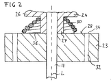
- FIG. 2 shows a detail of the injection valve 1.
- the armature 23 comprises a number of through holes 32, which form fluid passages between the fluid inlet portion 5 and the fluid outlet portion 7. First ends 34 of the through holes 32 are exposed on the top side 28 of the armature 23 outside the area 36 covered by the conical spring 30.
- the area 36 covered by the conical spring 30 is the inner area of the top side 28, where windings of the conical spring 30 are arranged.
- the area 36 is annular, extends around the base portion 27 of the upper retaining element 24 and has the outer diameter of the largest windings of the conical spring 30.
Landscapes
- Engineering & Computer Science (AREA)
- Chemical & Material Sciences (AREA)
- Combustion & Propulsion (AREA)
- Mechanical Engineering (AREA)
- General Engineering & Computer Science (AREA)
- Physics & Mathematics (AREA)
- Electromagnetism (AREA)
- Fuel-Injection Apparatus (AREA)
- Magnetically Actuated Valves (AREA)
Abstract
Description
- The present disclosure relates to a valve assembly for an injection valve and to an injection valve, e.g. a fuel injection valve of a vehicle. It particularly relates to solenoid injection valves.
- Such injection valves must be able to dose fluids even in the case of high fuel pressure. One design to ensure this is the "free-lift" design. According to this design, the armature of the electro-magnetic actuator unit travels about a "pre-stroke gap" before it engages the needle to open the injector. Thus, kinetic energy is accumulated before the actual opening.
- The "free-lift"-concept uses a so called free-lift spring that biases the armature away from an upper retaining element, which is fixed to the valve needle. When the actuator unit is energized, the armature travels against the load of this spring before engaging the upper retaining element for moving the valve needle. Generally, the further the armature travels before engaging the valve needle, the more kinetic energy it will have accumulated. Therefore, in order to manage high fuel pressures, a large spring travel is advantageous.
- On the other hand, a compact injector is advantageous as space is tight in automotive applications. Therefore, one solution is to arrange a free-lift spring in a recess in the armature. This, however, reduces the guidance length of the valve needle and can cause functional problems and wear.
- It is an object of the present disclosure to provide a valve assembly for an injection valve that overcomes the above mentioned difficulties and which provides a stable performance with a high maximum pressure.
- This object is achieved by means of a valve assembly according to the independent claim.
- Advantageous embodiments and developments are specified in the dependent claims, the following description and the drawings.
- According to one aspect, a valve assembly for an injection valve is provided, comprising a valve body with a central longitudinal axis comprising a cavity with a fluid inlet portion and a fluid outlet portion. The valve assembly further comprises a valve needle axially moveable in the cavity. In particular, the valve needle is displaceable in reciprocating fashion relative to the valve body. The valve needle is operable to prevent a fluid flow through the fluid outlet portion in a closing position and to release the fluid flow through the fluid outlet portion in further positions.
- The valve needle is fixedly connected to a retaining element, which extends in radial direction from the needle and is arranged in an axial region of the valve needle facing away from the fluid outlet portion. In the present context, this includes embodiments in which the retaining element is in one piece with the valve needle and projects in radial outward direction from a shaft of the valve needle.
- The valve assembly further comprises an armature for an electromagnetic actuator unit. The armature is axially movable in the cavity; specifically it is axially displaceable relative to the valve body in reciprocating fashion.
- The armature comprises a central axial opening through which the valve needle extends. In this way, the armature may be joined to the valve needle by form-fit The form-fit joint between the armature and the valve needle limits the movement of the armature only in radial direction. The armature is able to slide on the valve needle, i.e. it is axially displaceable in reciprocating fashion also relative to the valve needle.
- The armature acts on the needle by way of the upper retaining element. In particular, the is operable to engage in form-fit connection with the retaining element for axially displacing the valve needle away from the closing position.
- A conical spring is arranged around the central longitudinal axis between the retaining element and a top side of the armature facing the upper retaining element, biasing the armature away from the upper retaining element.
- This valve assembly has the advantage that almost the whole length of the conical spring can be used to full capacity, because windings of a conical spring can coil into each other when the spring is compressed, with the result, that in the case of maximum compression, the height of the conical spring may only be about e.g. two times the diameter of the spring wire. Thus, a large spring travel can be achieved with a conical spring in spite of limited available space. Hence, a particularly compact free-lift injector suitable for dosing high pressure fuel is created.
- In one embodiment, the valve assembly comprises a lower retaining element, which is fixed to the valve needle on a side of the armature remote from the retaining element. Therefore, the retaining element is also denoted as an upper retaining element in the following. In an expedient development, the conical spring biases the armature in contact with the lower retaining element.
- In one embodiment, the armature has a flat surface which is operable to engage in form fit connection with the upper retaining element, in particular for axially displacing the valve needle away from the closing position. In one development, the flat surface also represents a seat for the conical spring. The flat surface preferably extends perpendicular to the longitudinal axis. In this way, a simple geometry of the armature and/or easy assembly of the conical spring with the armature is/are achievable.
- In one embodiment, the upper retaining element comprises a sleeve portion which axially overlaps the conical spring and a collar portion projecting in radially outward direction beyond the sleeve portion and representing a seat for the conical spring. Preferably, the armature engages in form-fit connection with the sleeve portion for acting on the valve needle to move the valve needle axially. With advantage, the retaining element has a simple shape and at the same time reliably provides all necessary functions.
- According to one embodiment, the diameter of the windings of the conical spring increases at least by 2d per turn, wherein d is the diameter of spring wire. This embodiment has the advantage that each winding can coil into the previous one, so that the fully compressed spring is only slightly higher than the diameter d of one spring wire, i.e. about two times the diameter d.
- According to one embodiment, the diameter of the windings of the conical spring is minimal at a first end of the spring facing the upper retaining element and maximal at a second end facing the armature and increases in the direction towards the armature. The diameter of the windings may increase uniformly in between.
- According to this embodiment, the spring is oriented so that the small-diameter windings are facing upwards towards the upper retaining element. Thus, individual windings are prevented from being pushed into the gap between the upper retaining element and the armature, which could result in blocking the movement of the armature.
- According to one embodiment, the armature comprises a plurality of through holes forming fluid passages between the fluid inlet portion and the fluid outlet portion, wherein first ends of the through holes are exposed on the top side of the armature outside the area covered by the conical spring.
- The area covered by the conical spring is understood to be that part of the top side of the armature, onto which the windings of the spring coil when the spring is compressed, i.e. the inner annular part of the armature close to the needle up to the radius of the conical spring. In other words, the through holes are offset in radial outward direction with respect to the conical spring, in one embodiment at least in a plane comprising the above-mentioned flat surface of the armature.
- According to this embodiment, the through holes end outside this area, so that fluid flow through the through holes is not prevented by the conical spring.
- According to one aspect of the invention, an injection valve with the described valve assembly is provided, further comprising an electromagnetic actuator unit. The electromagnetic actuator unit may expediently comprise the armature. The electromagnetic actuator unit particularly comprises a coil which may be energized to induce a magnetic field which acts on the armature of the valve assembly for moving the armature in axial direction towards the upper retaining element. The injection valve may in particular be a fuel injection valve of a vehicle.
- Further advantages, advantageous embodiments and developments of the valve assembly for an injection valve, the fluid injection valve and the method for manufacturing a fluid injection valve will become apparent from the exemplary embodiments which are described below in association with the schematic figures.
- Figure 1
- shows a sectional view of an injection valve with a valve assembly according to one embodiment of the invention and
- Figure 2
- shows a detail of
figure 1 . -
Figure 1 shows an injection valve 1 that is in particular suitable for dosing fuel to an internal combustion engine. - The injection valve 1 comprises in particular a
valve assembly 3. Thevalve assembly 3 comprises avalve body 4 with a central longitudinal axis L. Ahousing 6 is partially arranged around thevalve body 4. - The
valve body 4 comprises acavity 9. Thecavity 9 has afluid outlet portion 7. Thefluid outlet portion 7 communicates with a fluid inlet portion 5 which is provided in thevalve body 4. The fluid inlet portion 5 and thefluid outlet portion 7 are in particular positioned at opposite axial ends of thevalve body 4. Thecavity 9 takes in a valve needle 11. The valve needle 11 comprises aneedle shaft 15 and a sealingball 13 welded to the tip of theneedle shaft 15. - In a closing position of the valve needle 11, it sealingly rests on a seat plate 17 having at least one injection nozzle. A preloaded calibration spring 18 exerts a force on the needle 11 in axial direction towards the closing position. The
fluid outlet portion 7 is arranged near the seat plate 17. - In the closing position of the valve needle 11, a fluid flow through the at least one injection nozzle is prevented. The injection nozzle may be, for example, an injection hole. However, it may also be of some other type suitable for dosing fluid.
- The
valve assembly 3 is provided with an electro-magnetic actuator unit 19. The electro-magnetic actuator unit 19 comprises acoil 21, which is preferably arranged inside thehousing 6. Furthermore, the electro-magnetic actuator unit 19 comprises anarmature 23. Thehousing 6, parts of thevalve body 4 and thearmature 23 form an electromagnetic circuit. - The
actuator unit 19 further comprises apole piece 25. - The
armature 23 is axially movable in thecavity 9 and fixed to the valve needle 11 by form fit, this joint preventing movement of thearmature 23 relative to the valve needle 11 in radial direction. The needle 11 extends through a central axial opening in thearmature 23. Thearmature 23 is axially movable relative to the valve needle 11, i.e. it may slide on the needle 11. - At an axial end of the valve needle 11 the valve needle 11 comprises an
upper retaining element 24. Theupper retaining element 24 has a sleeve portion - in the following denoted as base portion 27 - extending circumferentially around the axial end of the valve needle 11 and further comprises a collar portion 26 extending in radial direction away from the valve needle 11 so that it projects in radial outward direction beyond thebase potion 27. Theupper retaining element 24 is an integrally formed, one-pieced part. In this embodiment, the upper retainingelement 24 is a separate piece but fixedly connected to the axial end of the valve needle 11. In further embodiments, the upper retainingelement 24 may be formed in one piece with the valve needle 11. - Between the upper retaining
element 24 and atop side 28 of thearmature 23 facing the upper retainingelement 24, aconical spring 30 is arranged around the central longitudinal axis L and around thebase portion 27 of the upper retainingelement 24, biasing thearmature 23 away from the upper retainingelement 24. - The
conical spring 30 rests on a flat surface of thearmature 23 on thetop side 28 of thearmature 23 with its first end, which has a large diameter. It rests against the collar 26 of the upper retainingelement 24 with its second end, which has a smaller diameter. - The
conical spring 30 comprises a number of windings, the diameter of which increases by at least 2d per turn, where d is the diameter of the spring wire. Thus, thespring 30 may be compressed tightly, taking up comparatively little space. Consequently, the spring travel of theconical spring 30 is comparatively large. - The
conical spring 30 enables a transmission of forces between thearmature 23 and the upper retainingelement 24. The dampening effect of thespring 30 enables that the wearing effects on thearmature 23 and/or on the valve needle 11 may be kept small during the opening or closing process of the valve needle 11. - In the closing position of the valve 1, there is a gap between the upper retaining
element 24 and thearmature 23, also called free-lift gap. When thecoil 21 is energized, thearmature 23 experiences a magnetic force and slides upwards towards thepole piece 25, moving in axial direction away from thefluid outlet portion 7, thereby compressing theconical spring 30. - Only after having travelled the gap and after having taken up kinetic energy, the flat surface of the
armature 23 on which theconical spring 30 is seated hits thebase portion 27 of the upper retainingelement 24 and takes the valve needle 11 with it via the form-fit connection with the upper retainingelement 24 that is established in this way. Consequently, the valve needle 11 moves in axial direction out of the closing position of the valve 1. When thearmature 23 starts to travel upwards, a gap is formed between thearmature 23 and a disc-shapedelement 43 fixedly connected to the needle 11 on the side of thearmature 23 remote from the upper retainingelement 24. The disc-shapedelement 43 represents a lower retaining element which limits axial displacability of thearmature 23 relative to the valve needle 11 in direction away from the upper retainingelement 24. - When the
coil 21 is de-energized, the calibration spring 18 is able to force the valve needle 11 to move in axial direction into its closing position. At the end of the closing transient, when the valve needle 11 hits the seat plate 17, thearmature 23 detaches from the upper retainingelement 24 and travels downwards towards the disc-shapedelement 43, closing the gap betweenarmature 23 and disc-shapedelement 43. -
Figure 2 shows a detail of the injection valve 1. Thearmature 23 comprises a number of throughholes 32, which form fluid passages between the fluid inlet portion 5 and thefluid outlet portion 7. First ends 34 of the throughholes 32 are exposed on thetop side 28 of thearmature 23 outside thearea 36 covered by theconical spring 30. Thearea 36 covered by theconical spring 30 is the inner area of thetop side 28, where windings of theconical spring 30 are arranged. Hence, thearea 36 is annular, extends around thebase portion 27 of the upper retainingelement 24 and has the outer diameter of the largest windings of theconical spring 30.
Claims (7)
- Valve assembly (3) for an injection valve (1), comprising- a valve body (4) with a central longitudinal axis comprising a cavity (9) with a fluid inlet portion (5) and a fluid outlet portion (7),- a valve needle (11) axially moveable in the cavity (9), the valve needle (11) preventing a fluid flow through the fluid outlet portion (7) in a closing position and releasing the fluid flow through the fluid outlet portion (7) in further positions, the valve needle (11) being fixedly connected to a retaining element (24) which extends in radial direction and is arranged in an axial region of the valve needle (11) facing away from the fluid outlet portion (7),- an armature (23) for an electromagnetic actuator unit (19) axially movable in the cavity (9), the armature (23) comprising a central axial opening through which the valve needle (11) extends, the armature (23) being able to slide on the valve needle (11) and acting on the needle (11) by way of the retaining element (24), wherein a conical spring (30) is arranged around the central longitudinal axis between the retaining element (24) and a top side (28) of the armature (23) facing the retaining element (24), biasing the armature (23) away from the retaining element (24).
- Valve assembly (3) according to the preceding claim,
wherein the armature (23) has a flat surface which is operable to engage in form fit connection with the retaining element (24) and which represents a seat for the conical spring (30). - Valve assembly (3) according to one of the preceding claims, wherein the retaining element (24) comprises a sleeve portion which axially overlaps the conical spring (30) and a collar portion projecting in radially outward direction beyond the sleeve portion and representing a seat for the conical spring (30).
- Valve assembly (3) according to one of the preceding claims,
wherein a diameter of the windings of the conical spring (30) increases at least by 2d per turn, wherein d is the diameter of spring wire. - Valve assembly (3) according to one of the preceding claims,
wherein the diameter of the windings of the conical spring (30) is minimal at a first end of the spring (30) facing the retaining element (24) and maximal at a second end facing the armature (23) and increases in the direction towards the armature (23). - Valve assembly (3) according to one of the preceding claims,
wherein the armature (23) comprises a number of through holes (32) forming fluid passages between the fluid inlet portion (5) and the fluid outlet portion (7), wherein first ends (34) of the through holes (32) are exposed on the top side (28) of the armature (23) outside the area (36) covered by the conical spring (30). - Injection valve (1) with a valve assembly (3) according to one of the preceding claims, further comprising an electromagnetic actuator unit.
Priority Applications (4)
| Application Number | Priority Date | Filing Date | Title |
|---|---|---|---|
| EP16176098.8A EP3260695B8 (en) | 2016-06-24 | 2016-06-24 | Valve assembly for an injection valve and injection valve |
| KR1020170076836A KR101979087B1 (en) | 2016-06-24 | 2017-06-16 | Valve assembly for an injection valve and injection valve |
| US15/630,403 US10309360B2 (en) | 2016-06-24 | 2017-06-22 | Valve assembly for an injection valve and injection valve |
| CN201710484086.3A CN107542612B (en) | 2016-06-24 | 2017-06-23 | Valve assembly for injection valve and injection valve |
Applications Claiming Priority (1)
| Application Number | Priority Date | Filing Date | Title |
|---|---|---|---|
| EP16176098.8A EP3260695B8 (en) | 2016-06-24 | 2016-06-24 | Valve assembly for an injection valve and injection valve |
Publications (3)
| Publication Number | Publication Date |
|---|---|
| EP3260695A1 true EP3260695A1 (en) | 2017-12-27 |
| EP3260695B1 EP3260695B1 (en) | 2019-05-01 |
| EP3260695B8 EP3260695B8 (en) | 2019-07-17 |
Family
ID=56203265
Family Applications (1)
| Application Number | Title | Priority Date | Filing Date |
|---|---|---|---|
| EP16176098.8A Active EP3260695B8 (en) | 2016-06-24 | 2016-06-24 | Valve assembly for an injection valve and injection valve |
Country Status (4)
| Country | Link |
|---|---|
| US (1) | US10309360B2 (en) |
| EP (1) | EP3260695B8 (en) |
| KR (1) | KR101979087B1 (en) |
| CN (1) | CN107542612B (en) |
Cited By (1)
| Publication number | Priority date | Publication date | Assignee | Title |
|---|---|---|---|---|
| WO2019137680A1 (en) * | 2018-01-11 | 2019-07-18 | Robert Bosch Gmbh | Valve for metering a fluid |
Families Citing this family (1)
| Publication number | Priority date | Publication date | Assignee | Title |
|---|---|---|---|---|
| CN111344483B (en) * | 2017-11-22 | 2022-03-08 | 日立安斯泰莫株式会社 | fuel injection device |
Citations (4)
| Publication number | Priority date | Publication date | Assignee | Title |
|---|---|---|---|---|
| US5044561A (en) * | 1986-12-19 | 1991-09-03 | Robert Bosch Gmbh | Injection valve for fuel injection systems |
| EP2535552A1 (en) * | 2011-06-15 | 2012-12-19 | Continental Automotive GmbH | Valve assembly for an injection valve and injection valve |
| EP2789844A1 (en) * | 2011-12-09 | 2014-10-15 | Kefico Corporation | Direct injection fuel injector |
| EP2985445A1 (en) * | 2014-08-14 | 2016-02-17 | Continental Automotive GmbH | Solenoid actuated fluid injection valve |
Family Cites Families (13)
| Publication number | Priority date | Publication date | Assignee | Title |
|---|---|---|---|---|
| KR19980054461U (en) * | 1996-12-31 | 1998-10-07 | 박병재 | Conical coil spring |
| DE19948238A1 (en) * | 1999-10-07 | 2001-04-19 | Bosch Gmbh Robert | Fuel injector |
| DE10036811A1 (en) * | 2000-07-28 | 2002-02-07 | Bosch Gmbh Robert | Fuel injector |
| JP4483940B2 (en) * | 2007-12-21 | 2010-06-16 | 株式会社デンソー | Fuel injection valve |
| JP4935882B2 (en) * | 2009-03-05 | 2012-05-23 | 株式会社デンソー | Fuel injection valve |
| EP2333297B1 (en) | 2009-12-11 | 2013-03-20 | Continental Automotive GmbH | Valve assembly for an injection valve and injection valve |
| US8453951B2 (en) * | 2010-09-22 | 2013-06-04 | Delphi Technologies, Inc. | Fuel injector |
| JP5822269B2 (en) * | 2011-11-11 | 2015-11-24 | 株式会社ケーヒン | Electromagnetic fuel injection valve |
| JP5965253B2 (en) * | 2012-02-20 | 2016-08-03 | 株式会社デンソー | Fuel injection valve |
| DE102012210415A1 (en) | 2012-06-20 | 2013-12-24 | Robert Bosch Gmbh | Injector |
| JP5814870B2 (en) * | 2012-07-06 | 2015-11-17 | 日立オートモティブシステムズ株式会社 | Electromagnetic fuel injection valve |
| JP6187422B2 (en) * | 2014-09-17 | 2017-08-30 | 株式会社デンソー | Fuel injection valve |
| JP6175475B2 (en) * | 2015-11-20 | 2017-08-02 | 株式会社ケーヒン | Electromagnetic fuel injection valve |
-
2016
- 2016-06-24 EP EP16176098.8A patent/EP3260695B8/en active Active
-
2017
- 2017-06-16 KR KR1020170076836A patent/KR101979087B1/en active Active
- 2017-06-22 US US15/630,403 patent/US10309360B2/en active Active
- 2017-06-23 CN CN201710484086.3A patent/CN107542612B/en active Active
Patent Citations (4)
| Publication number | Priority date | Publication date | Assignee | Title |
|---|---|---|---|---|
| US5044561A (en) * | 1986-12-19 | 1991-09-03 | Robert Bosch Gmbh | Injection valve for fuel injection systems |
| EP2535552A1 (en) * | 2011-06-15 | 2012-12-19 | Continental Automotive GmbH | Valve assembly for an injection valve and injection valve |
| EP2789844A1 (en) * | 2011-12-09 | 2014-10-15 | Kefico Corporation | Direct injection fuel injector |
| EP2985445A1 (en) * | 2014-08-14 | 2016-02-17 | Continental Automotive GmbH | Solenoid actuated fluid injection valve |
Cited By (3)
| Publication number | Priority date | Publication date | Assignee | Title |
|---|---|---|---|---|
| WO2019137680A1 (en) * | 2018-01-11 | 2019-07-18 | Robert Bosch Gmbh | Valve for metering a fluid |
| KR20200103716A (en) * | 2018-01-11 | 2020-09-02 | 로베르트 보쉬 게엠베하 | Fluid metering valve |
| US11698049B2 (en) | 2018-01-11 | 2023-07-11 | Robert Bosch Gmbh | Valve for metering a fluid |
Also Published As
| Publication number | Publication date |
|---|---|
| KR20180001461A (en) | 2018-01-04 |
| EP3260695B1 (en) | 2019-05-01 |
| CN107542612B (en) | 2020-01-21 |
| US10309360B2 (en) | 2019-06-04 |
| US20170370340A1 (en) | 2017-12-28 |
| CN107542612A (en) | 2018-01-05 |
| KR101979087B1 (en) | 2019-05-15 |
| EP3260695B8 (en) | 2019-07-17 |
Similar Documents
| Publication | Publication Date | Title |
|---|---|---|
| US9651011B2 (en) | Valve assembly for an injection valve and injection valve | |
| EP2535552B1 (en) | Valve assembly for an injection valve and injection valve | |
| CN108368805B (en) | Valve assemblies and injection valves for injection valves | |
| US10731614B2 (en) | Fuel injection valve with an anti bounce device | |
| US9528610B2 (en) | Valve assembly for an injection valve and injection valve | |
| EP2597296B1 (en) | Valve assembly for an injection valve and injection valve | |
| US10550809B2 (en) | Valve assembly for an injection valve and injection valve | |
| US20150260138A1 (en) | Valve Assembly for an Injection Valve and Injection Valve | |
| US9995262B2 (en) | Fluid injection valve | |
| US10309360B2 (en) | Valve assembly for an injection valve and injection valve | |
| EP2837813A1 (en) | Valve assembly for an injection valve and injection valve | |
| EP3263884A1 (en) | Injection valve with a magnetic ring element | |
| CN109154261B (en) | Valve assembly for injection valve and injection valve | |
| EP2378106A1 (en) | Valve assembly for an injection valve and injection valve | |
| EP2933472A1 (en) | Fuel injection valve for an internal combustion engine | |
| US20190211786A1 (en) | Valve Assembly for an Injection Valve and Injection Valve | |
| EP3611368A1 (en) | Valve assembly and fuel injection valve | |
| EP2241743A1 (en) | Valve assembly for an injection valve and injection valve | |
| EP2703633A1 (en) | Valve assembly for an injection valve and injection valve |
Legal Events
| Date | Code | Title | Description |
|---|---|---|---|
| PUAI | Public reference made under article 153(3) epc to a published international application that has entered the european phase |
Free format text: ORIGINAL CODE: 0009012 |
|
| STAA | Information on the status of an ep patent application or granted ep patent |
Free format text: STATUS: THE APPLICATION HAS BEEN PUBLISHED |
|
| AK | Designated contracting states |
Kind code of ref document: A1 Designated state(s): AL AT BE BG CH CY CZ DE DK EE ES FI FR GB GR HR HU IE IS IT LI LT LU LV MC MK MT NL NO PL PT RO RS SE SI SK SM TR |
|
| AX | Request for extension of the european patent |
Extension state: BA ME |
|
| STAA | Information on the status of an ep patent application or granted ep patent |
Free format text: STATUS: REQUEST FOR EXAMINATION WAS MADE |
|
| 17P | Request for examination filed |
Effective date: 20180627 |
|
| RBV | Designated contracting states (corrected) |
Designated state(s): AL AT BE BG CH CY CZ DE DK EE ES FI FR GB GR HR HU IE IS IT LI LT LU LV MC MK MT NL NO PL PT RO RS SE SI SK SM TR |
|
| RIC1 | Information provided on ipc code assigned before grant |
Ipc: F02M 51/06 20060101AFI20180829BHEP Ipc: F02M 61/20 20060101ALI20180829BHEP |
|
| GRAP | Despatch of communication of intention to grant a patent |
Free format text: ORIGINAL CODE: EPIDOSNIGR1 |
|
| STAA | Information on the status of an ep patent application or granted ep patent |
Free format text: STATUS: GRANT OF PATENT IS INTENDED |
|
| INTG | Intention to grant announced |
Effective date: 20181119 |
|
| GRAS | Grant fee paid |
Free format text: ORIGINAL CODE: EPIDOSNIGR3 |
|
| GRAA | (expected) grant |
Free format text: ORIGINAL CODE: 0009210 |
|
| STAA | Information on the status of an ep patent application or granted ep patent |
Free format text: STATUS: THE PATENT HAS BEEN GRANTED |
|
| AK | Designated contracting states |
Kind code of ref document: B1 Designated state(s): AL AT BE BG CH CY CZ DE DK EE ES FI FR GB GR HR HU IE IS IT LI LT LU LV MC MK MT NL NO PL PT RO RS SE SI SK SM TR |
|
| REG | Reference to a national code |
Ref country code: GB Ref legal event code: FG4D |
|
| REG | Reference to a national code |
Ref country code: CH Ref legal event code: EP Ref country code: AT Ref legal event code: REF Ref document number: 1127254 Country of ref document: AT Kind code of ref document: T Effective date: 20190515 |
|
| REG | Reference to a national code |
Ref country code: DE Ref legal event code: R096 Ref document number: 602016013062 Country of ref document: DE |
|
| REG | Reference to a national code |
Ref country code: IE Ref legal event code: FG4D |
|
| REG | Reference to a national code |
Ref country code: CH Ref legal event code: PK Free format text: BERICHTIGUNG B8 |
|
| RAP2 | Party data changed (patent owner data changed or rights of a patent transferred) |
Owner name: CPT GROUP GMBH |
|
| REG | Reference to a national code |
Ref country code: NL Ref legal event code: MP Effective date: 20190501 |
|
| REG | Reference to a national code |
Ref country code: LT Ref legal event code: MG4D |
|
| PG25 | Lapsed in a contracting state [announced via postgrant information from national office to epo] |
Ref country code: SE Free format text: LAPSE BECAUSE OF FAILURE TO SUBMIT A TRANSLATION OF THE DESCRIPTION OR TO PAY THE FEE WITHIN THE PRESCRIBED TIME-LIMIT Effective date: 20190501 Ref country code: NO Free format text: LAPSE BECAUSE OF FAILURE TO SUBMIT A TRANSLATION OF THE DESCRIPTION OR TO PAY THE FEE WITHIN THE PRESCRIBED TIME-LIMIT Effective date: 20190801 Ref country code: FI Free format text: LAPSE BECAUSE OF FAILURE TO SUBMIT A TRANSLATION OF THE DESCRIPTION OR TO PAY THE FEE WITHIN THE PRESCRIBED TIME-LIMIT Effective date: 20190501 Ref country code: PT Free format text: LAPSE BECAUSE OF FAILURE TO SUBMIT A TRANSLATION OF THE DESCRIPTION OR TO PAY THE FEE WITHIN THE PRESCRIBED TIME-LIMIT Effective date: 20190901 Ref country code: AL Free format text: LAPSE BECAUSE OF FAILURE TO SUBMIT A TRANSLATION OF THE DESCRIPTION OR TO PAY THE FEE WITHIN THE PRESCRIBED TIME-LIMIT Effective date: 20190501 Ref country code: LT Free format text: LAPSE BECAUSE OF FAILURE TO SUBMIT A TRANSLATION OF THE DESCRIPTION OR TO PAY THE FEE WITHIN THE PRESCRIBED TIME-LIMIT Effective date: 20190501 Ref country code: HR Free format text: LAPSE BECAUSE OF FAILURE TO SUBMIT A TRANSLATION OF THE DESCRIPTION OR TO PAY THE FEE WITHIN THE PRESCRIBED TIME-LIMIT Effective date: 20190501 Ref country code: ES Free format text: LAPSE BECAUSE OF FAILURE TO SUBMIT A TRANSLATION OF THE DESCRIPTION OR TO PAY THE FEE WITHIN THE PRESCRIBED TIME-LIMIT Effective date: 20190501 Ref country code: NL Free format text: LAPSE BECAUSE OF FAILURE TO SUBMIT A TRANSLATION OF THE DESCRIPTION OR TO PAY THE FEE WITHIN THE PRESCRIBED TIME-LIMIT Effective date: 20190501 |
|
| PG25 | Lapsed in a contracting state [announced via postgrant information from national office to epo] |
Ref country code: LV Free format text: LAPSE BECAUSE OF FAILURE TO SUBMIT A TRANSLATION OF THE DESCRIPTION OR TO PAY THE FEE WITHIN THE PRESCRIBED TIME-LIMIT Effective date: 20190501 Ref country code: RS Free format text: LAPSE BECAUSE OF FAILURE TO SUBMIT A TRANSLATION OF THE DESCRIPTION OR TO PAY THE FEE WITHIN THE PRESCRIBED TIME-LIMIT Effective date: 20190501 Ref country code: BG Free format text: LAPSE BECAUSE OF FAILURE TO SUBMIT A TRANSLATION OF THE DESCRIPTION OR TO PAY THE FEE WITHIN THE PRESCRIBED TIME-LIMIT Effective date: 20190801 Ref country code: GR Free format text: LAPSE BECAUSE OF FAILURE TO SUBMIT A TRANSLATION OF THE DESCRIPTION OR TO PAY THE FEE WITHIN THE PRESCRIBED TIME-LIMIT Effective date: 20190802 |
|
| REG | Reference to a national code |
Ref country code: AT Ref legal event code: MK05 Ref document number: 1127254 Country of ref document: AT Kind code of ref document: T Effective date: 20190501 |
|
| RAP2 | Party data changed (patent owner data changed or rights of a patent transferred) |
Owner name: VITESCO TECHNOLOGIES GMBH |
|
| PG25 | Lapsed in a contracting state [announced via postgrant information from national office to epo] |
Ref country code: IS Free format text: LAPSE BECAUSE OF FAILURE TO SUBMIT A TRANSLATION OF THE DESCRIPTION OR TO PAY THE FEE WITHIN THE PRESCRIBED TIME-LIMIT Effective date: 20190901 |
|
| PG25 | Lapsed in a contracting state [announced via postgrant information from national office to epo] |
Ref country code: MC Free format text: LAPSE BECAUSE OF FAILURE TO SUBMIT A TRANSLATION OF THE DESCRIPTION OR TO PAY THE FEE WITHIN THE PRESCRIBED TIME-LIMIT Effective date: 20190501 Ref country code: AT Free format text: LAPSE BECAUSE OF FAILURE TO SUBMIT A TRANSLATION OF THE DESCRIPTION OR TO PAY THE FEE WITHIN THE PRESCRIBED TIME-LIMIT Effective date: 20190501 Ref country code: DK Free format text: LAPSE BECAUSE OF FAILURE TO SUBMIT A TRANSLATION OF THE DESCRIPTION OR TO PAY THE FEE WITHIN THE PRESCRIBED TIME-LIMIT Effective date: 20190501 Ref country code: EE Free format text: LAPSE BECAUSE OF FAILURE TO SUBMIT A TRANSLATION OF THE DESCRIPTION OR TO PAY THE FEE WITHIN THE PRESCRIBED TIME-LIMIT Effective date: 20190501 Ref country code: SK Free format text: LAPSE BECAUSE OF FAILURE TO SUBMIT A TRANSLATION OF THE DESCRIPTION OR TO PAY THE FEE WITHIN THE PRESCRIBED TIME-LIMIT Effective date: 20190501 Ref country code: RO Free format text: LAPSE BECAUSE OF FAILURE TO SUBMIT A TRANSLATION OF THE DESCRIPTION OR TO PAY THE FEE WITHIN THE PRESCRIBED TIME-LIMIT Effective date: 20190501 Ref country code: CZ Free format text: LAPSE BECAUSE OF FAILURE TO SUBMIT A TRANSLATION OF THE DESCRIPTION OR TO PAY THE FEE WITHIN THE PRESCRIBED TIME-LIMIT Effective date: 20190501 |
|
| REG | Reference to a national code |
Ref country code: CH Ref legal event code: PL |
|
| REG | Reference to a national code |
Ref country code: DE Ref legal event code: R097 Ref document number: 602016013062 Country of ref document: DE |
|
| PG25 | Lapsed in a contracting state [announced via postgrant information from national office to epo] |
Ref country code: SM Free format text: LAPSE BECAUSE OF FAILURE TO SUBMIT A TRANSLATION OF THE DESCRIPTION OR TO PAY THE FEE WITHIN THE PRESCRIBED TIME-LIMIT Effective date: 20190501 |
|
| PLBE | No opposition filed within time limit |
Free format text: ORIGINAL CODE: 0009261 |
|
| STAA | Information on the status of an ep patent application or granted ep patent |
Free format text: STATUS: NO OPPOSITION FILED WITHIN TIME LIMIT |
|
| REG | Reference to a national code |
Ref country code: BE Ref legal event code: MM Effective date: 20190630 |
|
| PG25 | Lapsed in a contracting state [announced via postgrant information from national office to epo] |
Ref country code: TR Free format text: LAPSE BECAUSE OF FAILURE TO SUBMIT A TRANSLATION OF THE DESCRIPTION OR TO PAY THE FEE WITHIN THE PRESCRIBED TIME-LIMIT Effective date: 20190501 |
|
| 26N | No opposition filed |
Effective date: 20200204 |
|
| PG25 | Lapsed in a contracting state [announced via postgrant information from national office to epo] |
Ref country code: PL Free format text: LAPSE BECAUSE OF FAILURE TO SUBMIT A TRANSLATION OF THE DESCRIPTION OR TO PAY THE FEE WITHIN THE PRESCRIBED TIME-LIMIT Effective date: 20190501 Ref country code: IE Free format text: LAPSE BECAUSE OF NON-PAYMENT OF DUE FEES Effective date: 20190624 |
|
| PG25 | Lapsed in a contracting state [announced via postgrant information from national office to epo] |
Ref country code: SI Free format text: LAPSE BECAUSE OF FAILURE TO SUBMIT A TRANSLATION OF THE DESCRIPTION OR TO PAY THE FEE WITHIN THE PRESCRIBED TIME-LIMIT Effective date: 20190501 Ref country code: LU Free format text: LAPSE BECAUSE OF NON-PAYMENT OF DUE FEES Effective date: 20190624 Ref country code: LI Free format text: LAPSE BECAUSE OF NON-PAYMENT OF DUE FEES Effective date: 20190630 Ref country code: CH Free format text: LAPSE BECAUSE OF NON-PAYMENT OF DUE FEES Effective date: 20190630 Ref country code: BE Free format text: LAPSE BECAUSE OF NON-PAYMENT OF DUE FEES Effective date: 20190630 |
|
| REG | Reference to a national code |
Ref country code: DE Ref legal event code: R081 Ref document number: 602016013062 Country of ref document: DE Owner name: VITESCO TECHNOLOGIES GMBH, DE Free format text: FORMER OWNER: CONTINENTAL AUTOMOTIVE GMBH, 30165 HANNOVER, DE |
|
| PG25 | Lapsed in a contracting state [announced via postgrant information from national office to epo] |
Ref country code: CY Free format text: LAPSE BECAUSE OF FAILURE TO SUBMIT A TRANSLATION OF THE DESCRIPTION OR TO PAY THE FEE WITHIN THE PRESCRIBED TIME-LIMIT Effective date: 20190501 |
|
| PG25 | Lapsed in a contracting state [announced via postgrant information from national office to epo] |
Ref country code: HU Free format text: LAPSE BECAUSE OF FAILURE TO SUBMIT A TRANSLATION OF THE DESCRIPTION OR TO PAY THE FEE WITHIN THE PRESCRIBED TIME-LIMIT; INVALID AB INITIO Effective date: 20160624 Ref country code: MT Free format text: LAPSE BECAUSE OF FAILURE TO SUBMIT A TRANSLATION OF THE DESCRIPTION OR TO PAY THE FEE WITHIN THE PRESCRIBED TIME-LIMIT Effective date: 20190501 |
|
| REG | Reference to a national code |
Ref country code: DE Ref legal event code: R081 Ref document number: 602016013062 Country of ref document: DE Owner name: SCHAEFFLER TECHNOLOGIES AG & CO. KG, DE Free format text: FORMER OWNER: VITESCO TECHNOLOGIES GMBH, 30165 HANNOVER, DE Ref country code: DE Ref legal event code: R081 Ref document number: 602016013062 Country of ref document: DE Owner name: VITESCO TECHNOLOGIES GMBH, DE Free format text: FORMER OWNER: VITESCO TECHNOLOGIES GMBH, 30165 HANNOVER, DE |
|
| PG25 | Lapsed in a contracting state [announced via postgrant information from national office to epo] |
Ref country code: MK Free format text: LAPSE BECAUSE OF FAILURE TO SUBMIT A TRANSLATION OF THE DESCRIPTION OR TO PAY THE FEE WITHIN THE PRESCRIBED TIME-LIMIT Effective date: 20190501 |
|
| P01 | Opt-out of the competence of the unified patent court (upc) registered |
Effective date: 20230530 |
|
| REG | Reference to a national code |
Ref country code: DE Ref legal event code: R081 Ref document number: 602016013062 Country of ref document: DE Owner name: SCHAEFFLER TECHNOLOGIES AG & CO. KG, DE Free format text: FORMER OWNER: VITESCO TECHNOLOGIES GMBH, 93055 REGENSBURG, DE |
|
| PGFP | Annual fee paid to national office [announced via postgrant information from national office to epo] |
Ref country code: GB Payment date: 20260625 Year of fee payment: 11 |
|
| PGFP | Annual fee paid to national office [announced via postgrant information from national office to epo] |
Ref country code: IT Payment date: 20260623 Year of fee payment: 11 |
|
| PGFP | Annual fee paid to national office [announced via postgrant information from national office to epo] |
Ref country code: DE Payment date: 20260630 Year of fee payment: 11 |
|
| PGFP | Annual fee paid to national office [announced via postgrant information from national office to epo] |
Ref country code: FR Payment date: 20260626 Year of fee payment: 11 |