EP2535552A1 - Valve assembly for an injection valve and injection valve - Google Patents
Valve assembly for an injection valve and injection valve Download PDFInfo
- Publication number
- EP2535552A1 EP2535552A1 EP11169988A EP11169988A EP2535552A1 EP 2535552 A1 EP2535552 A1 EP 2535552A1 EP 11169988 A EP11169988 A EP 11169988A EP 11169988 A EP11169988 A EP 11169988A EP 2535552 A1 EP2535552 A1 EP 2535552A1
- Authority
- EP
- European Patent Office
- Prior art keywords
- armature
- valve
- valve needle
- cavity
- stop surface
- Prior art date
- Legal status (The legal status is an assumption and is not a legal conclusion. Google has not performed a legal analysis and makes no representation as to the accuracy of the status listed.)
- Granted
Links
Images

Classifications
-
- F—MECHANICAL ENGINEERING; LIGHTING; HEATING; WEAPONS; BLASTING
- F02—COMBUSTION ENGINES; HOT-GAS OR COMBUSTION-PRODUCT ENGINE PLANTS
- F02M—SUPPLYING COMBUSTION ENGINES IN GENERAL WITH COMBUSTIBLE MIXTURES OR CONSTITUENTS THEREOF
- F02M51/00—Fuel-injection apparatus characterised by being operated electrically
- F02M51/06—Injectors peculiar thereto with means directly operating the valve needle
- F02M51/061—Injectors peculiar thereto with means directly operating the valve needle using electromagnetic operating means
- F02M51/0625—Injectors peculiar thereto with means directly operating the valve needle using electromagnetic operating means characterised by arrangement of mobile armatures
- F02M51/0635—Injectors peculiar thereto with means directly operating the valve needle using electromagnetic operating means characterised by arrangement of mobile armatures having a plate-shaped or undulated armature not entering the winding
- F02M51/066—Injectors peculiar thereto with means directly operating the valve needle using electromagnetic operating means characterised by arrangement of mobile armatures having a plate-shaped or undulated armature not entering the winding the armature and the valve being allowed to move relatively to each other or not being attached to each other
-
- F—MECHANICAL ENGINEERING; LIGHTING; HEATING; WEAPONS; BLASTING
- F02—COMBUSTION ENGINES; HOT-GAS OR COMBUSTION-PRODUCT ENGINE PLANTS
- F02M—SUPPLYING COMBUSTION ENGINES IN GENERAL WITH COMBUSTIBLE MIXTURES OR CONSTITUENTS THEREOF
- F02M51/00—Fuel-injection apparatus characterised by being operated electrically
- F02M51/06—Injectors peculiar thereto with means directly operating the valve needle
- F02M51/061—Injectors peculiar thereto with means directly operating the valve needle using electromagnetic operating means
- F02M51/0625—Injectors peculiar thereto with means directly operating the valve needle using electromagnetic operating means characterised by arrangement of mobile armatures
- F02M51/0664—Injectors peculiar thereto with means directly operating the valve needle using electromagnetic operating means characterised by arrangement of mobile armatures having a cylindrically or partly cylindrically shaped armature, e.g. entering the winding; having a plate-shaped or undulated armature entering the winding
-
- F—MECHANICAL ENGINEERING; LIGHTING; HEATING; WEAPONS; BLASTING
- F02—COMBUSTION ENGINES; HOT-GAS OR COMBUSTION-PRODUCT ENGINE PLANTS
- F02M—SUPPLYING COMBUSTION ENGINES IN GENERAL WITH COMBUSTIBLE MIXTURES OR CONSTITUENTS THEREOF
- F02M2200/00—Details of fuel-injection apparatus, not otherwise provided for
- F02M2200/30—Fuel-injection apparatus having mechanical parts, the movement of which is damped
- F02M2200/306—Fuel-injection apparatus having mechanical parts, the movement of which is damped using mechanical means
Definitions
- the invention relates to a valve assembly for an injection valve and an injection valve.
- Injection valves are in wide spread use, in particular for internal combustion engines where they may be arranged in order to dose the fluid into an intake manifold of the internal combustion engine or directly into the combustion chamber of a cylinder of the internal combustion engine.
- injection valves are manufactured in various forms in order to satisfy the various needs for the various combustion engines. Therefore, for example, their length, their diameter and also various elements of the injection valve being responsible for the way the fluid is dosed may vary in a wide range.
- injection valves may accommodate an actuator for actuating a needle of the injection valve, which may, for example, be an electromagnetic actuator or piezo electric actuator.
- the respective injection valve may be suited to dose fluids under very high pressures.
- the injection valve may be suited to dose very small quantities of fluid under very high pressures. These pressures may be in case of a gasoline engine, for example, in the range of up to 200 bar and in the case of diesel engines in the range of more than 2000 bar.
- the object of the invention is to create a valve assembly which facilitates a reliable and precise function.
- the invention is distinguished by a valve assembly for an injection valve, comprising a valve body including a central longitudinal axis, the valve body comprising a cavity with a fluid inlet portion and a fluid outlet portion, a valve needle axially movable in the cavity, the valve needle preventing a fluid flow through the fluid outlet portion in a closing position and releasing the fluid flow through the fluid outlet portion in further positions, the valve needle comprising a protrusion extending in radial direction, and an electro-magnetic actuator unit being designed to actuate the valve needle.
- the electro-magnetic actuator unit comprises an armature axially movable in the cavity.
- the armature comprises an armature cavity.
- the armature cavity has a first stop surface and a second stop surface.
- the normals of the stop surfaces are essentially orientated in axial direction.
- the second stop surface essentially faces the first stop surface.
- the protrusion of the valve needle is arranged in the armature cavity axially between the first stop surface and the second stop surface in such a manner that a relative movement between the valve needle and the armature in axial direction is limited.
- the armature comprises an armature main body and an armature retainer.
- the armature retainer is fixedly coupled to the armature main body and is shaped in a manner that the armature retainer and the armature main body form the armature cavity. This has the advantage that the armature with the armature cavity may be easily manufactured.
- the armature retainer is shaped as an annular collar. This has the advantage that the armature retainer may be easily manufactured. Furthermore, the armature cavity with the stop surfaces may have a well-defined shape.
- the longitudinal cross section of the armature retainer has an L-shape. This has the advantage that the armature retainer may be easily manufactured.
- a spring element is arranged in the armature cavity axially between the protrusion of the valve needle and the armature retainer.
- the spring element is a coil spring or a wave spring. This has the advantage that a simple shape of the spring element and a low cost solution is possible. Furthermore, a secure arrangement of the spring element in the armature cavity may be obtained.
- An injection valve 10 that is in particular suitable for dosing fuel to an internal combustion engine comprises in particular a valve assembly 12 and an inlet tube 14.
- the valve assembly 12 comprises a valve body 16 with a central longitudinal axis L.
- the valve assembly 12 has a housing 18 which is partially arranged around the valve body 16.
- a cavity 20 is arranged in the valve body 16.
- the cavity 20 comprises a fluid outlet portion 21 and a fluid inlet portion 22.
- the fluid outlet portion 21 is in hydraulic communication with the fluid inlet portion 22.
- the cavity 20 takes in a valve needle 24 and an armature 26.
- the valve needle 24 is axially movable in the cavity 20.
- the valve needle 24 comprises a protrusion 28.
- the protrusion 28 is formed as a collar around the valve needle 24.
- the protrusion 28 is fixedly coupled to the valve needle 24.
- the armature 26 is axially movable in the cavity 20.
- a main spring 30 is arranged in a recess 32 which is provided in the inlet tube 14.
- the main spring 30 is mechanically coupled to a guide element 33.
- the guide element 33 is fixedly coupled to the valve needle 24.
- the main spring 30 exerts a force on the guide element 33 and, consequently, on the valve needle 24 towards an injection nozzle 34 of the injection valve 10.
- the injection nozzle 34 may be, for example, an injection hole.
- the armature 26 has an armature cavity 36.
- the armature 26 has an armature main body 38 and an armature retainer 40.
- the armature retainer 40 is fixedly coupled to the armature main body 38.
- the armature main body 38 and the armature retainer 40 form the armature cavity 36.
- the armature retainer 40 is shaped as a collar with an L-shaped longitudinal cross section.
- the armature cavity 36 has a first stop surface 42a and a second stop surface 42b.
- the normal of the first stop surface 42a and the normal of the second stop surface 42b are orientated in axial direction.
- the second stop surface 42b faces the first stop surface 42a.
- the protrusion 28 of the valve needle 24 is arranged in the armature cavity 36 axially between the first stop surface 42a and the second stop surface 42b. By this a relative movement between the valve needle 24 and the armature 26 in axial direction is limited.
- valve needle 24 In a closing position of the valve needle 24 it sealingly rests on a seat plate 44 by this preventing a fluid flow through the at least one injection nozzle 34.
- the valve assembly 12 is provided with an actuator unit 46 that is preferably an electro-magnetic actuator.
- the electro-magnetic actuator unit 46 comprises a coil 48, which is preferably arranged inside the housing 18. Furthermore, the electro-magnetic actuator unit 46 comprises the armature main body 38.
- the valve body 16, the housing 18, the inlet tube 14 and the armature main body 38 are forming an electromagnetic circuit.
- a spring element 50 is arranged in the armature cavity 36 axially between the protrusion 28 of the valve needle 24 and the armature retainer 40 of the armature 26.
- the spring element 50 causes an axial basic distance (blind lift B, Figure 2 ) between the protrusion 28 and the armature retainer 40 during a static condition of the valve assembly 12.
- the spring element 50 enables a dampened transmission of movements between the armature retainer 40 of the armature 26 and the protrusion 28 of the valve needle 24.
- the actuator unit 46 may affect an electro-magnetic force on the armature 26.
- the armature 26 is attracted by the electro-magnetic actuator unit 46 with the coil 48 and moves in axial direction away from the fluid outlet portion 21.
- the armature 26 takes the valve needle 24 with it. Consequently, the valve needle 24 moves in axial direction out of the closing position.
- the gap between the valve body 16 and the valve needle 24 at the axial end of the injection valve 10 facing away from of the actuator unit 46 forms a fluid path and fluid can pass through the injection nozzle 34.
- the main spring 30 can force the valve needle 24 to move in axial direction in its closing position. It is depending on the force balance between the force on the valve needle 24 caused by the actuator unit 46 with the coil 48 and the force on the valve needle 24 caused by the main spring 30 whether the valve needle 24 is in its closing position or not.
- the arrangement of the protrusion 28 of the valve needle 24 in the armature cavity 36 between the two stop surfaces 42a, 42b enables a limited range of relative positions between the armature 26 and the protrusion 28 of the valve needle 24.
- the valve needle 24 may float between the two stop surfaces 42a, 42b of the armature 26 in the range of the blind lift B to perform the opening and closing movement.
- the wearing between the protrusion 28 of the valve needle 24 and the armature 26 can be kept small. Consequently, a stable performance of the operation of the injection valve 10 can be obtained over a long term operating period of the injection valve 10. Furthermore, as the contact surface between the protrusion 28 of the valve needle 24 and the armature 26 may be so large that the contact pressure between the protrusion 28 of the valve needle 24 and the armature 26 can be kept small, a protective coating in the contact area between the armature retainer 40 and the protrusion 28 of the valve needle 24 may be avoided.
- the protrusion 28 may be separate from the valve needle 24 and the armature retainer 40 may be separate from the armature 26
- the protrusion 28 of the valve needle 24 and the armature retainer 40 need not be part of the magnetic circuit. Therefore, a simple hardening process can be carried out for the surfaces of the protrusion 28 of the valve needle 24 and the armature retainer 40 to keep the wearing of these two components small.
- an overshoot of the valve needle 24 and the armature 26 during the opening and the closing of the injection valve 10 can be kept small so that a very good dynamic control of the injection valve 10 can be obtained.
- the guide element 33 is performing a guide function only without any additional task to perform the movement of the valve needle 24 during the opening or closing process.
- the armature 26 is decoupled from the valve needle 24 in a manner that the protrusion 28 allows the relative movement of the armature 26 relative to the valve needle 24.
- the protrusion 28 may limit the overshoot of the armature 26 as well as the overshoot of the valve needle 24.
- the wearing effects on the armature 26 and/or the valve needle 24 in the contact area between the valve needle 24 and/or the armature 26 may be kept small during the opening or closing of the valve needle 24. Consequently, a good long term contact between the valve needle 24 and the armature 26 may be obtained.
Abstract
Description
- The invention relates to a valve assembly for an injection valve and an injection valve.
- Injection valves are in wide spread use, in particular for internal combustion engines where they may be arranged in order to dose the fluid into an intake manifold of the internal combustion engine or directly into the combustion chamber of a cylinder of the internal combustion engine.
- Injection valves are manufactured in various forms in order to satisfy the various needs for the various combustion engines. Therefore, for example, their length, their diameter and also various elements of the injection valve being responsible for the way the fluid is dosed may vary in a wide range. In addition to that, injection valves may accommodate an actuator for actuating a needle of the injection valve, which may, for example, be an electromagnetic actuator or piezo electric actuator.
- In order to enhance the combustion process in view of the creation of unwanted emissions, the respective injection valve may be suited to dose fluids under very high pressures. In particular, the injection valve may be suited to dose very small quantities of fluid under very high pressures. These pressures may be in case of a gasoline engine, for example, in the range of up to 200 bar and in the case of diesel engines in the range of more than 2000 bar.
- The object of the invention is to create a valve assembly which facilitates a reliable and precise function.
- This object is achieved by the features of the independent claim. Advantageous embodiments of the invention are given in the sub-claims.
- The invention is distinguished by a valve assembly for an injection valve, comprising a valve body including a central longitudinal axis, the valve body comprising a cavity with a fluid inlet portion and a fluid outlet portion, a valve needle axially movable in the cavity, the valve needle preventing a fluid flow through the fluid outlet portion in a closing position and releasing the fluid flow through the fluid outlet portion in further positions, the valve needle comprising a protrusion extending in radial direction, and an electro-magnetic actuator unit being designed to actuate the valve needle. The electro-magnetic actuator unit comprises an armature axially movable in the cavity. The armature comprises an armature cavity. The armature cavity has a first stop surface and a second stop surface. The normals of the stop surfaces are essentially orientated in axial direction. The second stop surface essentially faces the first stop surface. The protrusion of the valve needle is arranged in the armature cavity axially between the first stop surface and the second stop surface in such a manner that a relative movement between the valve needle and the armature in axial direction is limited.
- This has the advantage that the arrangement of the protrusion of the valve needle in the armature cavity between the two stop surfaces provides a clearly defined range of the relative position between the armature and the valve needle. Furthermore, a large contact surface between the armature retainer and the protrusion of the valve needle may be obtained. Consequently, the wearing between the protrusion of the valve needle and the armature can be kept small. Consequently, a stable performance of the operation of the injection valve can be obtained over a long time. Furthermore, a protective coating in a contact area between the armature retainer and the protrusion of the valve needle may be avoided.
- In an advantageous embodiment the armature comprises an armature main body and an armature retainer. The armature retainer is fixedly coupled to the armature main body and is shaped in a manner that the armature retainer and the armature main body form the armature cavity. This has the advantage that the armature with the armature cavity may be easily manufactured.
- In a further advantageous embodiment the armature retainer is shaped as an annular collar. This has the advantage that the armature retainer may be easily manufactured. Furthermore, the armature cavity with the stop surfaces may have a well-defined shape.
- In a further advantageous embodiment the longitudinal cross section of the armature retainer has an L-shape. This has the advantage that the armature retainer may be easily manufactured.
- In a further advantageous embodiment a spring element is arranged in the armature cavity axially between the protrusion of the valve needle and the armature retainer. This has the advantage that the armature acts on the valve needle via the spring element so that the movement of the valve needle may be delayed relative to the armature. By this the dynamic behavior of the valve needle may be dampened. Consequently, wearing effects on the valve needle and/or on the armature in the contact area between the valve needle and/or the armature may be kept small. Consequently, a good long term contact between the valve needle and the armature may be obtained and a static flow drift caused by the wearing effects may be kept small.
- In a further advantageous embodiment the spring element is a coil spring or a wave spring. This has the advantage that a simple shape of the spring element and a low cost solution is possible. Furthermore, a secure arrangement of the spring element in the armature cavity may be obtained.
- Exemplary embodiments of the invention are explained in the following with the aid of schematic drawings. These are as follows:
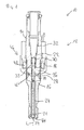
- Figure 1
- an injection valve with a valve assembly in a longitudinal section view, and
- Figure 2
- an enlarged view of a part of the valve assembly.
- Elements of the same design and function that appear in different illustrations are identified by the same reference character.
- An
injection valve 10 that is in particular suitable for dosing fuel to an internal combustion engine comprises in particular avalve assembly 12 and aninlet tube 14. - The
valve assembly 12 comprises avalve body 16 with a central longitudinal axis L. Thevalve assembly 12 has ahousing 18 which is partially arranged around thevalve body 16. - A
cavity 20 is arranged in thevalve body 16. Thecavity 20 comprises afluid outlet portion 21 and afluid inlet portion 22. Thefluid outlet portion 21 is in hydraulic communication with thefluid inlet portion 22. - The
cavity 20 takes in avalve needle 24 and anarmature 26. Thevalve needle 24 is axially movable in thecavity 20. Thevalve needle 24 comprises aprotrusion 28. Preferably, theprotrusion 28 is formed as a collar around thevalve needle 24. Theprotrusion 28 is fixedly coupled to thevalve needle 24. Thearmature 26 is axially movable in thecavity 20. - A
main spring 30 is arranged in arecess 32 which is provided in theinlet tube 14. Themain spring 30 is mechanically coupled to aguide element 33. Theguide element 33 is fixedly coupled to thevalve needle 24. Themain spring 30 exerts a force on theguide element 33 and, consequently, on thevalve needle 24 towards an injection nozzle 34 of theinjection valve 10. The injection nozzle 34 may be, for example, an injection hole. - The
armature 26 has anarmature cavity 36. Thearmature 26 has an armaturemain body 38 and anarmature retainer 40. Thearmature retainer 40 is fixedly coupled to the armaturemain body 38. The armaturemain body 38 and thearmature retainer 40 form thearmature cavity 36. Preferably, thearmature retainer 40 is shaped as a collar with an L-shaped longitudinal cross section. - The
armature cavity 36 has a first stop surface 42a and asecond stop surface 42b. The normal of the first stop surface 42a and the normal of thesecond stop surface 42b are orientated in axial direction. Thesecond stop surface 42b faces the first stop surface 42a. Theprotrusion 28 of thevalve needle 24 is arranged in thearmature cavity 36 axially between the first stop surface 42a and thesecond stop surface 42b. By this a relative movement between thevalve needle 24 and thearmature 26 in axial direction is limited. - In a closing position of the
valve needle 24 it sealingly rests on a seat plate 44 by this preventing a fluid flow through the at least one injection nozzle 34. - The
valve assembly 12 is provided with anactuator unit 46 that is preferably an electro-magnetic actuator. The electro-magnetic actuator unit 46 comprises acoil 48, which is preferably arranged inside thehousing 18. Furthermore, the electro-magnetic actuator unit 46 comprises the armaturemain body 38. Thevalve body 16, thehousing 18, theinlet tube 14 and the armaturemain body 38 are forming an electromagnetic circuit. - A
spring element 50 is arranged in thearmature cavity 36 axially between theprotrusion 28 of thevalve needle 24 and thearmature retainer 40 of thearmature 26. Thespring element 50 causes an axial basic distance (blind lift B,Figure 2 ) between theprotrusion 28 and thearmature retainer 40 during a static condition of thevalve assembly 12. Thespring element 50 enables a dampened transmission of movements between thearmature retainer 40 of thearmature 26 and theprotrusion 28 of thevalve needle 24. - In the following, the function of the
injection valve 10 is described in detail: - The fluid is led through the
recess 32 of thefluid inlet tube 14 to thefluid inlet portion 22 in thevalve body 16. Subsequently, the fluid is led towards thefluid outlet portion 21 in thevalve body 16. - The
valve needle 24 prevents a fluid flow through thefluid outlet portion 21 in thevalve body 16 in a closing position of thevalve needle 24. Outside of the closing position of thevalve needle 24, thevalve needle 24 enables the fluid flow through thefluid outlet portion 21. - In the case when the electro-
magnetic actuator unit 46 with thecoil 48 gets energized theactuator unit 46 may affect an electro-magnetic force on thearmature 26. Thearmature 26 is attracted by the electro-magnetic actuator unit 46 with thecoil 48 and moves in axial direction away from thefluid outlet portion 21. After thearmature 26 has overcome the blind lift B between thearmature 26 and theprotrusion 28 of thevalve needle 24 thearmature 26 takes thevalve needle 24 with it. Consequently, thevalve needle 24 moves in axial direction out of the closing position. Outside of the closing position of thevalve needle 24 the gap between thevalve body 16 and thevalve needle 24 at the axial end of theinjection valve 10 facing away from of theactuator unit 46 forms a fluid path and fluid can pass through the injection nozzle 34. - In the case when the
actuator unit 46 is de-energized themain spring 30 can force thevalve needle 24 to move in axial direction in its closing position. It is depending on the force balance between the force on thevalve needle 24 caused by theactuator unit 46 with thecoil 48 and the force on thevalve needle 24 caused by themain spring 30 whether thevalve needle 24 is in its closing position or not. - The arrangement of the
protrusion 28 of thevalve needle 24 in thearmature cavity 36 between the twostop surfaces 42a, 42b enables a limited range of relative positions between thearmature 26 and theprotrusion 28 of thevalve needle 24. Thevalve needle 24 may float between the twostop surfaces 42a, 42b of thearmature 26 in the range of the blind lift B to perform the opening and closing movement. - As a large contact surface between the
armature retainer 40 and theprotrusion 28 of thevalve needle 24 can be obtained, the wearing between theprotrusion 28 of thevalve needle 24 and thearmature 26 can be kept small. Consequently, a stable performance of the operation of theinjection valve 10 can be obtained over a long term operating period of theinjection valve 10. Furthermore, as the contact surface between theprotrusion 28 of thevalve needle 24 and thearmature 26 may be so large that the contact pressure between theprotrusion 28 of thevalve needle 24 and thearmature 26 can be kept small, a protective coating in the contact area between thearmature retainer 40 and theprotrusion 28 of thevalve needle 24 may be avoided. - Additionally, as the
protrusion 28 may be separate from thevalve needle 24 and thearmature retainer 40 may be separate from thearmature 26, theprotrusion 28 of thevalve needle 24 and thearmature retainer 40 need not be part of the magnetic circuit. Therefore, a simple hardening process can be carried out for the surfaces of theprotrusion 28 of thevalve needle 24 and thearmature retainer 40 to keep the wearing of these two components small. - Additionally, an overshoot of the
valve needle 24 and thearmature 26 during the opening and the closing of theinjection valve 10 can be kept small so that a very good dynamic control of theinjection valve 10 can be obtained. - Furthermore, the
guide element 33 is performing a guide function only without any additional task to perform the movement of thevalve needle 24 during the opening or closing process. - Additionally, the
armature 26 is decoupled from thevalve needle 24 in a manner that theprotrusion 28 allows the relative movement of thearmature 26 relative to thevalve needle 24. Theprotrusion 28 may limit the overshoot of thearmature 26 as well as the overshoot of thevalve needle 24. - Due to the spring element 50 a reliable transmission of the movement of the
armature 26 to thevalve needle 24 can be obtained. The dynamic behavior of thevalve needle 24 is dampened. - Therefore, the wearing effects on the
armature 26 and/or thevalve needle 24 in the contact area between thevalve needle 24 and/or thearmature 26 may be kept small during the opening or closing of thevalve needle 24. Consequently, a good long term contact between thevalve needle 24 and thearmature 26 may be obtained.
Claims (7)
- Valve assembly (12) for an injection valve (10), comprising- a valve body (16) including a central longitudinal axis (L), the valve body (16) comprising a cavity (20) with a fluid inlet portion (22) and a fluid outlet portion (21),- a valve needle (24) axially movable in the cavity (20), the valve needle (24) preventing a fluid flow through the fluid outlet portion (21) in a closing position and releasing the fluid flow through the fluid outlet portion (21) in further positions, the valve needle (24) comprising a protrusion (28) extending in radial direction, and- an electro-magnetic actuator unit (46) being designed to actuate the valve needle (24), the electro-magnetic actuator unit (46) comprising an armature (26) axially movable in the cavity (20),
wherein the armature (26) comprises an armature cavity (36), the armature cavity (36) having a first stop surface (42a) and a second stop surface (42b), the normals of the stop surfaces (42a, 42b) being essentially orientated in axial direction, the second stop surface (42b) essentially facing the first stop surface (42a), and the protrusion (28) of the valve needle (24) being arranged in the armature cavity (36) axially between the first stop surface (42a) and the second stop surface (42b) in such a manner that a relative movement between the valve needle (24) and the armature (26) in axial direction is limited. - Valve assembly (12) according to claim 1, wherein the armature (26) comprises an armature main body (38) and an armature retainer (40), the armature retainer (40) being fixedly coupled to the armature main body (38) and being shaped in a manner that the armature retainer (40) and the armature main body (38) form the armature cavity (36).
- Valve assembly (12) according to claim 2, wherein the armature retainer (40) is shaped as an annular collar.
- Valve assembly (12) according to claim 2 or 3, wherein the longitudinal cross section of the armature retainer (40) has a L-shape.
- Valve assembly (12) according to one of the claims 2 to 4, wherein a spring element (50) is arranged in the armature cavity (36) axially between the protrusion (28) of the valve needle (24) and the armature retainer (40).
- Valve assembly (12) according to claim 5, wherein the spring element (50) is a coil spring or a wave spring.
- Injection valve (10) with a valve assembly (12) according to one of the preceding claims.
Priority Applications (4)
| Application Number | Priority Date | Filing Date | Title |
|---|---|---|---|
| EP11169988.0A EP2535552B1 (en) | 2011-06-15 | 2011-06-15 | Valve assembly for an injection valve and injection valve |
| KR1020120064552A KR101964793B1 (en) | 2011-06-15 | 2012-06-15 | Valve assembly for an injection valve and injection valve |
| CN201210268966.4A CN102828873B (en) | 2011-06-15 | 2012-06-15 | The valve module of injection valve and injection valve |
| US13/524,151 US8931718B2 (en) | 2011-06-15 | 2012-06-15 | Valve assembly for an injection valve and injection valve |
Applications Claiming Priority (1)
| Application Number | Priority Date | Filing Date | Title |
|---|---|---|---|
| EP11169988.0A EP2535552B1 (en) | 2011-06-15 | 2011-06-15 | Valve assembly for an injection valve and injection valve |
Publications (2)
| Publication Number | Publication Date |
|---|---|
| EP2535552A1 true EP2535552A1 (en) | 2012-12-19 |
| EP2535552B1 EP2535552B1 (en) | 2015-02-25 |
Family
ID=44773458
Family Applications (1)
| Application Number | Title | Priority Date | Filing Date |
|---|---|---|---|
| EP11169988.0A Active EP2535552B1 (en) | 2011-06-15 | 2011-06-15 | Valve assembly for an injection valve and injection valve |
Country Status (4)
| Country | Link |
|---|---|
| US (1) | US8931718B2 (en) |
| EP (1) | EP2535552B1 (en) |
| KR (1) | KR101964793B1 (en) |
| CN (1) | CN102828873B (en) |
Cited By (2)
| Publication number | Priority date | Publication date | Assignee | Title |
|---|---|---|---|---|
| EP2985445A1 (en) * | 2014-08-14 | 2016-02-17 | Continental Automotive GmbH | Solenoid actuated fluid injection valve |
| EP3260695A1 (en) * | 2016-06-24 | 2017-12-27 | Continental Automotive GmbH | Valve assembly for an injection valve and injection valve |
Families Citing this family (12)
| Publication number | Priority date | Publication date | Assignee | Title |
|---|---|---|---|---|
| WO2013060717A1 (en) * | 2011-10-26 | 2013-05-02 | Continental Automotive Gmbh | Valve assembly for an injection valve and injection valve |
| KR20150006044A (en) * | 2012-05-08 | 2015-01-15 | 콘티넨탈 오토모티브 게엠베하 | Valve assembly for an injection valve and injection valve |
| JP6186126B2 (en) * | 2013-01-24 | 2017-08-23 | 日立オートモティブシステムズ株式会社 | Fuel injection device |
| EP2851551B1 (en) * | 2013-09-20 | 2016-05-25 | Continental Automotive GmbH | Fluid injection valve |
| EP2860386A1 (en) * | 2013-10-10 | 2015-04-15 | Continental Automotive GmbH | Injector for a combustion engine |
| EP2896813B1 (en) * | 2014-01-17 | 2018-01-10 | Continental Automotive GmbH | Fuel injection valve for an internal combustion engine |
| EP3009658B1 (en) * | 2014-10-15 | 2017-09-06 | Continental Automotive GmbH | Injector for injecting fluid |
| EP3009663B1 (en) * | 2014-10-15 | 2020-06-24 | Vitesco Technologies GmbH | Valve assembly and fluid injector |
| CN108138715B (en) * | 2015-10-15 | 2022-02-25 | 大陆汽车有限公司 | Fuel injection valve with anti-bouncing device, combustion engine and vehicle |
| EP3184794B1 (en) * | 2015-12-21 | 2018-08-22 | Continental Automotive GmbH | Valve assembly and fluid injection valve |
| US11326566B2 (en) * | 2017-03-02 | 2022-05-10 | Briggs & Stratton, Llc | Transport valve system for outdoor power equipment |
| EP3816431B1 (en) * | 2019-10-30 | 2023-10-18 | Vitesco Technologies GmbH | Fluid injector for an internal combustion engine comprising a pressure compensator element |
Citations (3)
| Publication number | Priority date | Publication date | Assignee | Title |
|---|---|---|---|---|
| EP1460263A1 (en) * | 2003-03-19 | 2004-09-22 | Siemens Aktiengesellschaft | Injection valve with a needle biased by a spring |
| EP1550804A1 (en) * | 2003-12-29 | 2005-07-06 | Robert Bosch Gmbh | Fuel injection valve |
| DE102004056424A1 (en) * | 2004-11-23 | 2006-05-24 | Robert Bosch Gmbh | Fuel injecting valve for internal combustion engine, has slots provided along axial extension of pole piece which serves as magnetic internal pole, and parallel to symmetric axis of pole piece |
Family Cites Families (11)
| Publication number | Priority date | Publication date | Assignee | Title |
|---|---|---|---|---|
| US4646974A (en) * | 1985-05-06 | 1987-03-03 | General Motors Corporation | Electromagnetic fuel injector with orifice director plate |
| US5544816A (en) * | 1994-08-18 | 1996-08-13 | Siemens Automotive L.P. | Housing for coil of solenoid-operated fuel injector |
| US5465910A (en) * | 1994-08-18 | 1995-11-14 | Siemens Automotive Corporation | Overmolded cover for fuel injector power group and method |
| US5494223A (en) * | 1994-08-18 | 1996-02-27 | Siemens Automotive L.P. | Fuel injector having improved parallelism of impacting armature surface to impacted stop surface |
| DE10142302A1 (en) * | 2001-08-29 | 2003-03-20 | Bosch Gmbh Robert | Fuel injection valve, for the direct fuel injection at an IC motor, has a guide sleeve for the armature return spring, within an axial recess at the valve needle to give a force fit bond with the armature and a firm seating for the spring |
| DE102004024533A1 (en) * | 2004-05-18 | 2005-12-15 | Robert Bosch Gmbh | Fuel injector |
| US7086615B2 (en) * | 2004-05-19 | 2006-08-08 | Siemens Vdo Automotive Corporation | Fuel injector including an orifice disc and a method of forming an oblique spiral fuel flow |
| JP4637931B2 (en) | 2008-05-22 | 2011-02-23 | 三菱電機株式会社 | Fuel injection valve |
| EP2322797B1 (en) * | 2009-11-12 | 2012-10-31 | Delphi Technologies Holding S.à.r.l. | Armature for a Solenoid Actuator |
| EP2527637B1 (en) * | 2011-05-23 | 2014-10-08 | Continental Automotive GmbH | Injector for injecting fluid |
| US8910882B2 (en) | 2011-06-23 | 2014-12-16 | Caterpillar Inc. | Fuel injector having reduced armature cavity pressure |
-
2011
- 2011-06-15 EP EP11169988.0A patent/EP2535552B1/en active Active
-
2012
- 2012-06-15 CN CN201210268966.4A patent/CN102828873B/en active Active
- 2012-06-15 KR KR1020120064552A patent/KR101964793B1/en active IP Right Grant
- 2012-06-15 US US13/524,151 patent/US8931718B2/en not_active Expired - Fee Related
Patent Citations (3)
| Publication number | Priority date | Publication date | Assignee | Title |
|---|---|---|---|---|
| EP1460263A1 (en) * | 2003-03-19 | 2004-09-22 | Siemens Aktiengesellschaft | Injection valve with a needle biased by a spring |
| EP1550804A1 (en) * | 2003-12-29 | 2005-07-06 | Robert Bosch Gmbh | Fuel injection valve |
| DE102004056424A1 (en) * | 2004-11-23 | 2006-05-24 | Robert Bosch Gmbh | Fuel injecting valve for internal combustion engine, has slots provided along axial extension of pole piece which serves as magnetic internal pole, and parallel to symmetric axis of pole piece |
Cited By (5)
| Publication number | Priority date | Publication date | Assignee | Title |
|---|---|---|---|---|
| EP2985445A1 (en) * | 2014-08-14 | 2016-02-17 | Continental Automotive GmbH | Solenoid actuated fluid injection valve |
| WO2016023757A1 (en) * | 2014-08-14 | 2016-02-18 | Continental Automotive Gmbh | Solenoid actuated fluid injection valve |
| EP3260695A1 (en) * | 2016-06-24 | 2017-12-27 | Continental Automotive GmbH | Valve assembly for an injection valve and injection valve |
| CN107542612A (en) * | 2016-06-24 | 2018-01-05 | 大陆汽车有限公司 | Valve module and injection valve for injection valve |
| CN107542612B (en) * | 2016-06-24 | 2020-01-21 | 大陆汽车有限公司 | Valve assembly for an injection valve and injection valve |
Also Published As
| Publication number | Publication date |
|---|---|
| KR20120138710A (en) | 2012-12-26 |
| US20120318885A1 (en) | 2012-12-20 |
| KR101964793B1 (en) | 2019-04-02 |
| CN102828873A (en) | 2012-12-19 |
| CN102828873B (en) | 2016-07-06 |
| US8931718B2 (en) | 2015-01-13 |
| EP2535552B1 (en) | 2015-02-25 |
Similar Documents
| Publication | Publication Date | Title |
|---|---|---|
| EP2535552A1 (en) | Valve assembly for an injection valve and injection valve | |
| EP2333297B1 (en) | Valve assembly for an injection valve and injection valve | |
| EP2436910B1 (en) | Valve assembly for an injection valve and injection valve | |
| US9664161B2 (en) | Valve assembly for an injection valve and injection valve | |
| EP2436908A1 (en) | Valve assembly for an injection valve and injection valve | |
| US9528610B2 (en) | Valve assembly for an injection valve and injection valve | |
| EP2589786A1 (en) | Valve assembly for a control valve and control valve | |
| EP2597296B1 (en) | Valve assembly for an injection valve and injection valve | |
| EP2700807A1 (en) | Valve assembly for an injection valve and injection valve | |
| EP2378106A1 (en) | Valve assembly for an injection valve and injection valve | |
| EP2568155B1 (en) | Valve assembly and injection valve | |
| EP2375051A1 (en) | Valve assembly for an injection valve and injection valve | |
| EP2436909A1 (en) | Valve assembly for an injection valve and injection valve | |
| EP2719886A1 (en) | Valve assembly for an injection valve | |
| EP2466109A1 (en) | Valve assembly for an injection valve and injection valve | |
| EP2426350A1 (en) | Valve assembly for an injection valve and injection valve | |
| EP2363595A1 (en) | Valve assembly for an injection valve and injection valve | |
| EP2067981B1 (en) | Valve assembly for an injection valve and injection valve | |
| EP2385239A1 (en) | Valve assembly for an injection valve and injection valve | |
| EP2439400A1 (en) | Valve assembly for an injection valve and injection valve | |
| EP2241743B1 (en) | Valve assembly for an injection valve and injection valve | |
| EP2703633A1 (en) | Valve assembly for an injection valve and injection valve |
Legal Events
| Date | Code | Title | Description |
|---|---|---|---|
| PUAI | Public reference made under article 153(3) epc to a published international application that has entered the european phase |
Free format text: ORIGINAL CODE: 0009012 |
|
| AK | Designated contracting states |
Kind code of ref document: A1 Designated state(s): AL AT BE BG CH CY CZ DE DK EE ES FI FR GB GR HR HU IE IS IT LI LT LU LV MC MK MT NL NO PL PT RO RS SE SI SK SM TR |
|
| AX | Request for extension of the european patent |
Extension state: BA ME |
|
| 17P | Request for examination filed |
Effective date: 20130619 |
|
| RBV | Designated contracting states (corrected) |
Designated state(s): AL AT BE BG CH CY CZ DE DK EE ES FI FR GB GR HR HU IE IS IT LI LT LU LV MC MK MT NL NO PL PT RO RS SE SI SK SM TR |
|
| 17Q | First examination report despatched |
Effective date: 20131125 |
|
| RIC1 | Information provided on ipc code assigned before grant |
Ipc: F02M 63/00 20060101ALN20140625BHEP Ipc: F02M 51/06 20060101AFI20140625BHEP |
|
| RIC1 | Information provided on ipc code assigned before grant |
Ipc: F02M 63/00 20060101ALN20140627BHEP Ipc: F02M 51/06 20060101AFI20140627BHEP |
|
| RIC1 | Information provided on ipc code assigned before grant |
Ipc: F02M 63/00 20060101ALN20140805BHEP Ipc: F02M 51/06 20060101AFI20140805BHEP |
|
| GRAP | Despatch of communication of intention to grant a patent |
Free format text: ORIGINAL CODE: EPIDOSNIGR1 |
|
| INTG | Intention to grant announced |
Effective date: 20140916 |
|
| GRAS | Grant fee paid |
Free format text: ORIGINAL CODE: EPIDOSNIGR3 |
|
| GRAA | (expected) grant |
Free format text: ORIGINAL CODE: 0009210 |
|
| AK | Designated contracting states |
Kind code of ref document: B1 Designated state(s): AL AT BE BG CH CY CZ DE DK EE ES FI FR GB GR HR HU IE IS IT LI LT LU LV MC MK MT NL NO PL PT RO RS SE SI SK SM TR |
|
| REG | Reference to a national code |
Ref country code: GB Ref legal event code: FG4D |
|
| REG | Reference to a national code |
Ref country code: CH Ref legal event code: EP |
|
| REG | Reference to a national code |
Ref country code: IE Ref legal event code: FG4D |
|
| REG | Reference to a national code |
Ref country code: DE Ref legal event code: R096 Ref document number: 602011013899 Country of ref document: DE Effective date: 20150409 |
|
| REG | Reference to a national code |
Ref country code: AT Ref legal event code: REF Ref document number: 712213 Country of ref document: AT Kind code of ref document: T Effective date: 20150415 |
|
| REG | Reference to a national code |
Ref country code: NL Ref legal event code: VDEP Effective date: 20150225 |
|
| REG | Reference to a national code |
Ref country code: AT Ref legal event code: MK05 Ref document number: 712213 Country of ref document: AT Kind code of ref document: T Effective date: 20150225 |
|
| REG | Reference to a national code |
Ref country code: LT Ref legal event code: MG4D |
|
| PG25 | Lapsed in a contracting state [announced via postgrant information from national office to epo] |
Ref country code: LT Free format text: LAPSE BECAUSE OF FAILURE TO SUBMIT A TRANSLATION OF THE DESCRIPTION OR TO PAY THE FEE WITHIN THE PRESCRIBED TIME-LIMIT Effective date: 20150225 Ref country code: FI Free format text: LAPSE BECAUSE OF FAILURE TO SUBMIT A TRANSLATION OF THE DESCRIPTION OR TO PAY THE FEE WITHIN THE PRESCRIBED TIME-LIMIT Effective date: 20150225 Ref country code: HR Free format text: LAPSE BECAUSE OF FAILURE TO SUBMIT A TRANSLATION OF THE DESCRIPTION OR TO PAY THE FEE WITHIN THE PRESCRIBED TIME-LIMIT Effective date: 20150225 Ref country code: SE Free format text: LAPSE BECAUSE OF FAILURE TO SUBMIT A TRANSLATION OF THE DESCRIPTION OR TO PAY THE FEE WITHIN THE PRESCRIBED TIME-LIMIT Effective date: 20150225 Ref country code: NO Free format text: LAPSE BECAUSE OF FAILURE TO SUBMIT A TRANSLATION OF THE DESCRIPTION OR TO PAY THE FEE WITHIN THE PRESCRIBED TIME-LIMIT Effective date: 20150525 Ref country code: ES Free format text: LAPSE BECAUSE OF FAILURE TO SUBMIT A TRANSLATION OF THE DESCRIPTION OR TO PAY THE FEE WITHIN THE PRESCRIBED TIME-LIMIT Effective date: 20150225 |
|
| PG25 | Lapsed in a contracting state [announced via postgrant information from national office to epo] |
Ref country code: IS Free format text: LAPSE BECAUSE OF FAILURE TO SUBMIT A TRANSLATION OF THE DESCRIPTION OR TO PAY THE FEE WITHIN THE PRESCRIBED TIME-LIMIT Effective date: 20150625 Ref country code: RS Free format text: LAPSE BECAUSE OF FAILURE TO SUBMIT A TRANSLATION OF THE DESCRIPTION OR TO PAY THE FEE WITHIN THE PRESCRIBED TIME-LIMIT Effective date: 20150225 Ref country code: AT Free format text: LAPSE BECAUSE OF FAILURE TO SUBMIT A TRANSLATION OF THE DESCRIPTION OR TO PAY THE FEE WITHIN THE PRESCRIBED TIME-LIMIT Effective date: 20150225 Ref country code: LV Free format text: LAPSE BECAUSE OF FAILURE TO SUBMIT A TRANSLATION OF THE DESCRIPTION OR TO PAY THE FEE WITHIN THE PRESCRIBED TIME-LIMIT Effective date: 20150225 |
|
| PG25 | Lapsed in a contracting state [announced via postgrant information from national office to epo] |
Ref country code: NL Free format text: LAPSE BECAUSE OF FAILURE TO SUBMIT A TRANSLATION OF THE DESCRIPTION OR TO PAY THE FEE WITHIN THE PRESCRIBED TIME-LIMIT Effective date: 20150225 |
|
| PG25 | Lapsed in a contracting state [announced via postgrant information from national office to epo] |
Ref country code: SK Free format text: LAPSE BECAUSE OF FAILURE TO SUBMIT A TRANSLATION OF THE DESCRIPTION OR TO PAY THE FEE WITHIN THE PRESCRIBED TIME-LIMIT Effective date: 20150225 Ref country code: EE Free format text: LAPSE BECAUSE OF FAILURE TO SUBMIT A TRANSLATION OF THE DESCRIPTION OR TO PAY THE FEE WITHIN THE PRESCRIBED TIME-LIMIT Effective date: 20150225 Ref country code: CZ Free format text: LAPSE BECAUSE OF FAILURE TO SUBMIT A TRANSLATION OF THE DESCRIPTION OR TO PAY THE FEE WITHIN THE PRESCRIBED TIME-LIMIT Effective date: 20150225 Ref country code: RO Free format text: LAPSE BECAUSE OF FAILURE TO SUBMIT A TRANSLATION OF THE DESCRIPTION OR TO PAY THE FEE WITHIN THE PRESCRIBED TIME-LIMIT Effective date: 20150225 Ref country code: DK Free format text: LAPSE BECAUSE OF FAILURE TO SUBMIT A TRANSLATION OF THE DESCRIPTION OR TO PAY THE FEE WITHIN THE PRESCRIBED TIME-LIMIT Effective date: 20150225 |
|
| REG | Reference to a national code |
Ref country code: DE Ref legal event code: R097 Ref document number: 602011013899 Country of ref document: DE |
|
| PG25 | Lapsed in a contracting state [announced via postgrant information from national office to epo] |
Ref country code: PL Free format text: LAPSE BECAUSE OF FAILURE TO SUBMIT A TRANSLATION OF THE DESCRIPTION OR TO PAY THE FEE WITHIN THE PRESCRIBED TIME-LIMIT Effective date: 20150225 |
|
| PLBE | No opposition filed within time limit |
Free format text: ORIGINAL CODE: 0009261 |
|
| STAA | Information on the status of an ep patent application or granted ep patent |
Free format text: STATUS: NO OPPOSITION FILED WITHIN TIME LIMIT |
|
| PG25 | Lapsed in a contracting state [announced via postgrant information from national office to epo] |
Ref country code: MC Free format text: LAPSE BECAUSE OF FAILURE TO SUBMIT A TRANSLATION OF THE DESCRIPTION OR TO PAY THE FEE WITHIN THE PRESCRIBED TIME-LIMIT Effective date: 20150225 |
|
| REG | Reference to a national code |
Ref country code: CH Ref legal event code: PL |
|
| 26N | No opposition filed |
Effective date: 20151126 |
|
| PG25 | Lapsed in a contracting state [announced via postgrant information from national office to epo] |
Ref country code: SI Free format text: LAPSE BECAUSE OF FAILURE TO SUBMIT A TRANSLATION OF THE DESCRIPTION OR TO PAY THE FEE WITHIN THE PRESCRIBED TIME-LIMIT Effective date: 20150225 Ref country code: LU Free format text: LAPSE BECAUSE OF FAILURE TO SUBMIT A TRANSLATION OF THE DESCRIPTION OR TO PAY THE FEE WITHIN THE PRESCRIBED TIME-LIMIT Effective date: 20150615 |
|
| REG | Reference to a national code |
Ref country code: IE Ref legal event code: MM4A |
|
| PG25 | Lapsed in a contracting state [announced via postgrant information from national office to epo] |
Ref country code: IE Free format text: LAPSE BECAUSE OF NON-PAYMENT OF DUE FEES Effective date: 20150615 Ref country code: LI Free format text: LAPSE BECAUSE OF NON-PAYMENT OF DUE FEES Effective date: 20150630 Ref country code: CH Free format text: LAPSE BECAUSE OF NON-PAYMENT OF DUE FEES Effective date: 20150630 |
|
| PG25 | Lapsed in a contracting state [announced via postgrant information from national office to epo] |
Ref country code: BE Free format text: LAPSE BECAUSE OF FAILURE TO SUBMIT A TRANSLATION OF THE DESCRIPTION OR TO PAY THE FEE WITHIN THE PRESCRIBED TIME-LIMIT Effective date: 20150225 |
|
| REG | Reference to a national code |
Ref country code: FR Ref legal event code: PLFP Year of fee payment: 6 |
|
| PG25 | Lapsed in a contracting state [announced via postgrant information from national office to epo] |
Ref country code: MT Free format text: LAPSE BECAUSE OF FAILURE TO SUBMIT A TRANSLATION OF THE DESCRIPTION OR TO PAY THE FEE WITHIN THE PRESCRIBED TIME-LIMIT Effective date: 20150225 |
|
| PG25 | Lapsed in a contracting state [announced via postgrant information from national office to epo] |
Ref country code: HU Free format text: LAPSE BECAUSE OF FAILURE TO SUBMIT A TRANSLATION OF THE DESCRIPTION OR TO PAY THE FEE WITHIN THE PRESCRIBED TIME-LIMIT; INVALID AB INITIO Effective date: 20110615 Ref country code: SM Free format text: LAPSE BECAUSE OF FAILURE TO SUBMIT A TRANSLATION OF THE DESCRIPTION OR TO PAY THE FEE WITHIN THE PRESCRIBED TIME-LIMIT Effective date: 20150225 Ref country code: BG Free format text: LAPSE BECAUSE OF FAILURE TO SUBMIT A TRANSLATION OF THE DESCRIPTION OR TO PAY THE FEE WITHIN THE PRESCRIBED TIME-LIMIT Effective date: 20150225 |
|
| REG | Reference to a national code |
Ref country code: FR Ref legal event code: PLFP Year of fee payment: 7 |
|
| PG25 | Lapsed in a contracting state [announced via postgrant information from national office to epo] |
Ref country code: CY Free format text: LAPSE BECAUSE OF FAILURE TO SUBMIT A TRANSLATION OF THE DESCRIPTION OR TO PAY THE FEE WITHIN THE PRESCRIBED TIME-LIMIT Effective date: 20150225 Ref country code: GR Free format text: LAPSE BECAUSE OF FAILURE TO SUBMIT A TRANSLATION OF THE DESCRIPTION OR TO PAY THE FEE WITHIN THE PRESCRIBED TIME-LIMIT Effective date: 20150225 |
|
| PG25 | Lapsed in a contracting state [announced via postgrant information from national office to epo] |
Ref country code: TR Free format text: LAPSE BECAUSE OF FAILURE TO SUBMIT A TRANSLATION OF THE DESCRIPTION OR TO PAY THE FEE WITHIN THE PRESCRIBED TIME-LIMIT Effective date: 20150225 |
|
| REG | Reference to a national code |
Ref country code: FR Ref legal event code: PLFP Year of fee payment: 8 |
|
| PG25 | Lapsed in a contracting state [announced via postgrant information from national office to epo] |
Ref country code: MK Free format text: LAPSE BECAUSE OF FAILURE TO SUBMIT A TRANSLATION OF THE DESCRIPTION OR TO PAY THE FEE WITHIN THE PRESCRIBED TIME-LIMIT Effective date: 20150225 Ref country code: PT Free format text: LAPSE BECAUSE OF FAILURE TO SUBMIT A TRANSLATION OF THE DESCRIPTION OR TO PAY THE FEE WITHIN THE PRESCRIBED TIME-LIMIT Effective date: 20150225 |
|
| PG25 | Lapsed in a contracting state [announced via postgrant information from national office to epo] |
Ref country code: AL Free format text: LAPSE BECAUSE OF FAILURE TO SUBMIT A TRANSLATION OF THE DESCRIPTION OR TO PAY THE FEE WITHIN THE PRESCRIBED TIME-LIMIT Effective date: 20150225 |
|
| REG | Reference to a national code |
Ref country code: DE Ref legal event code: R081 Ref document number: 602011013899 Country of ref document: DE Owner name: VITESCO TECHNOLOGIES GMBH, DE Free format text: FORMER OWNER: CONTINENTAL AUTOMOTIVE GMBH, 30165 HANNOVER, DE |
|
| REG | Reference to a national code |
Ref country code: DE Ref legal event code: R084 Ref document number: 602011013899 Country of ref document: DE |
|
| REG | Reference to a national code |
Ref country code: DE Ref legal event code: R081 Ref document number: 602011013899 Country of ref document: DE Owner name: VITESCO TECHNOLOGIES GMBH, DE Free format text: FORMER OWNER: VITESCO TECHNOLOGIES GMBH, 30165 HANNOVER, DE |
|
| REG | Reference to a national code |
Ref country code: GB Ref legal event code: 732E Free format text: REGISTERED BETWEEN 20230427 AND 20230503 |
|
| P01 | Opt-out of the competence of the unified patent court (upc) registered |
Effective date: 20230530 |
|
| PGFP | Annual fee paid to national office [announced via postgrant information from national office to epo] |
Ref country code: FR Payment date: 20230627 Year of fee payment: 13 Ref country code: DE Payment date: 20230630 Year of fee payment: 13 |
|
| PGFP | Annual fee paid to national office [announced via postgrant information from national office to epo] |
Ref country code: IT Payment date: 20230623 Year of fee payment: 13 Ref country code: GB Payment date: 20230622 Year of fee payment: 13 |