EP3260690A1 - Torque control system for dpf regeneration - Google Patents
Torque control system for dpf regeneration Download PDFInfo
- Publication number
- EP3260690A1 EP3260690A1 EP15882760.0A EP15882760A EP3260690A1 EP 3260690 A1 EP3260690 A1 EP 3260690A1 EP 15882760 A EP15882760 A EP 15882760A EP 3260690 A1 EP3260690 A1 EP 3260690A1
- Authority
- EP
- European Patent Office
- Prior art keywords
- dpf regeneration
- engine torque
- regeneration
- predetermined target
- dpf
- Prior art date
- Legal status (The legal status is an assumption and is not a legal conclusion. Google has not performed a legal analysis and makes no representation as to the accuracy of the status listed.)
- Withdrawn
Links
Images

Classifications
-
- F—MECHANICAL ENGINEERING; LIGHTING; HEATING; WEAPONS; BLASTING
- F01—MACHINES OR ENGINES IN GENERAL; ENGINE PLANTS IN GENERAL; STEAM ENGINES
- F01N—GAS-FLOW SILENCERS OR EXHAUST APPARATUS FOR MACHINES OR ENGINES IN GENERAL; GAS-FLOW SILENCERS OR EXHAUST APPARATUS FOR INTERNAL-COMBUSTION ENGINES
- F01N3/00—Exhaust or silencing apparatus having means for purifying, rendering innocuous, or otherwise treating exhaust
- F01N3/02—Exhaust or silencing apparatus having means for purifying, rendering innocuous, or otherwise treating exhaust for cooling, or for removing solid constituents of, exhaust
- F01N3/021—Exhaust or silencing apparatus having means for purifying, rendering innocuous, or otherwise treating exhaust for cooling, or for removing solid constituents of, exhaust by means of filters
- F01N3/023—Exhaust or silencing apparatus having means for purifying, rendering innocuous, or otherwise treating exhaust for cooling, or for removing solid constituents of, exhaust by means of filters using means for regenerating the filters, e.g. by burning trapped particles
- F01N3/0238—Exhaust or silencing apparatus having means for purifying, rendering innocuous, or otherwise treating exhaust for cooling, or for removing solid constituents of, exhaust by means of filters using means for regenerating the filters, e.g. by burning trapped particles for regenerating during engine standstill
-
- F—MECHANICAL ENGINEERING; LIGHTING; HEATING; WEAPONS; BLASTING
- F01—MACHINES OR ENGINES IN GENERAL; ENGINE PLANTS IN GENERAL; STEAM ENGINES
- F01N—GAS-FLOW SILENCERS OR EXHAUST APPARATUS FOR MACHINES OR ENGINES IN GENERAL; GAS-FLOW SILENCERS OR EXHAUST APPARATUS FOR INTERNAL-COMBUSTION ENGINES
- F01N3/00—Exhaust or silencing apparatus having means for purifying, rendering innocuous, or otherwise treating exhaust
- F01N3/02—Exhaust or silencing apparatus having means for purifying, rendering innocuous, or otherwise treating exhaust for cooling, or for removing solid constituents of, exhaust
- F01N3/021—Exhaust or silencing apparatus having means for purifying, rendering innocuous, or otherwise treating exhaust for cooling, or for removing solid constituents of, exhaust by means of filters
- F01N3/023—Exhaust or silencing apparatus having means for purifying, rendering innocuous, or otherwise treating exhaust for cooling, or for removing solid constituents of, exhaust by means of filters using means for regenerating the filters, e.g. by burning trapped particles
-
- F—MECHANICAL ENGINEERING; LIGHTING; HEATING; WEAPONS; BLASTING
- F01—MACHINES OR ENGINES IN GENERAL; ENGINE PLANTS IN GENERAL; STEAM ENGINES
- F01N—GAS-FLOW SILENCERS OR EXHAUST APPARATUS FOR MACHINES OR ENGINES IN GENERAL; GAS-FLOW SILENCERS OR EXHAUST APPARATUS FOR INTERNAL-COMBUSTION ENGINES
- F01N9/00—Electrical control of exhaust gas treating apparatus
- F01N9/002—Electrical control of exhaust gas treating apparatus of filter regeneration
-
- F—MECHANICAL ENGINEERING; LIGHTING; HEATING; WEAPONS; BLASTING
- F02—COMBUSTION ENGINES; HOT-GAS OR COMBUSTION-PRODUCT ENGINE PLANTS
- F02D—CONTROLLING COMBUSTION ENGINES
- F02D29/00—Controlling engines, such controlling being peculiar to the devices driven thereby, the devices being other than parts or accessories essential to engine operation, e.g. controlling of engines by signals external thereto
- F02D29/04—Controlling engines, such controlling being peculiar to the devices driven thereby, the devices being other than parts or accessories essential to engine operation, e.g. controlling of engines by signals external thereto peculiar to engines driving pumps
-
- F—MECHANICAL ENGINEERING; LIGHTING; HEATING; WEAPONS; BLASTING
- F02—COMBUSTION ENGINES; HOT-GAS OR COMBUSTION-PRODUCT ENGINE PLANTS
- F02D—CONTROLLING COMBUSTION ENGINES
- F02D41/00—Electrical control of supply of combustible mixture or its constituents
- F02D41/02—Circuit arrangements for generating control signals
- F02D41/021—Introducing corrections for particular conditions exterior to the engine
-
- F—MECHANICAL ENGINEERING; LIGHTING; HEATING; WEAPONS; BLASTING
- F02—COMBUSTION ENGINES; HOT-GAS OR COMBUSTION-PRODUCT ENGINE PLANTS
- F02D—CONTROLLING COMBUSTION ENGINES
- F02D41/00—Electrical control of supply of combustible mixture or its constituents
- F02D41/02—Circuit arrangements for generating control signals
- F02D41/021—Introducing corrections for particular conditions exterior to the engine
- F02D41/0235—Introducing corrections for particular conditions exterior to the engine in relation with the state of the exhaust gas treating apparatus
- F02D41/024—Introducing corrections for particular conditions exterior to the engine in relation with the state of the exhaust gas treating apparatus to increase temperature of the exhaust gas treating apparatus
- F02D41/0245—Introducing corrections for particular conditions exterior to the engine in relation with the state of the exhaust gas treating apparatus to increase temperature of the exhaust gas treating apparatus by increasing temperature of the exhaust gas leaving the engine
-
- F—MECHANICAL ENGINEERING; LIGHTING; HEATING; WEAPONS; BLASTING
- F02—COMBUSTION ENGINES; HOT-GAS OR COMBUSTION-PRODUCT ENGINE PLANTS
- F02D—CONTROLLING COMBUSTION ENGINES
- F02D41/00—Electrical control of supply of combustible mixture or its constituents
- F02D41/02—Circuit arrangements for generating control signals
- F02D41/021—Introducing corrections for particular conditions exterior to the engine
- F02D41/0235—Introducing corrections for particular conditions exterior to the engine in relation with the state of the exhaust gas treating apparatus
- F02D41/027—Introducing corrections for particular conditions exterior to the engine in relation with the state of the exhaust gas treating apparatus to purge or regenerate the exhaust gas treating apparatus
- F02D41/029—Introducing corrections for particular conditions exterior to the engine in relation with the state of the exhaust gas treating apparatus to purge or regenerate the exhaust gas treating apparatus the exhaust gas treating apparatus being a particulate filter
-
- F—MECHANICAL ENGINEERING; LIGHTING; HEATING; WEAPONS; BLASTING
- F02—COMBUSTION ENGINES; HOT-GAS OR COMBUSTION-PRODUCT ENGINE PLANTS
- F02D—CONTROLLING COMBUSTION ENGINES
- F02D41/00—Electrical control of supply of combustible mixture or its constituents
- F02D41/02—Circuit arrangements for generating control signals
- F02D41/04—Introducing corrections for particular operating conditions
-
- F—MECHANICAL ENGINEERING; LIGHTING; HEATING; WEAPONS; BLASTING
- F02—COMBUSTION ENGINES; HOT-GAS OR COMBUSTION-PRODUCT ENGINE PLANTS
- F02D—CONTROLLING COMBUSTION ENGINES
- F02D41/00—Electrical control of supply of combustible mixture or its constituents
- F02D41/02—Circuit arrangements for generating control signals
- F02D41/04—Introducing corrections for particular operating conditions
- F02D41/06—Introducing corrections for particular operating conditions for engine starting or warming up
- F02D41/061—Introducing corrections for particular operating conditions for engine starting or warming up the corrections being time dependent
-
- F—MECHANICAL ENGINEERING; LIGHTING; HEATING; WEAPONS; BLASTING
- F02—COMBUSTION ENGINES; HOT-GAS OR COMBUSTION-PRODUCT ENGINE PLANTS
- F02D—CONTROLLING COMBUSTION ENGINES
- F02D41/00—Electrical control of supply of combustible mixture or its constituents
- F02D41/30—Controlling fuel injection
-
- F—MECHANICAL ENGINEERING; LIGHTING; HEATING; WEAPONS; BLASTING
- F02—COMBUSTION ENGINES; HOT-GAS OR COMBUSTION-PRODUCT ENGINE PLANTS
- F02D—CONTROLLING COMBUSTION ENGINES
- F02D41/00—Electrical control of supply of combustible mixture or its constituents
- F02D41/30—Controlling fuel injection
- F02D41/38—Controlling fuel injection of the high pressure type
- F02D41/3809—Common rail control systems
- F02D41/3827—Common rail control systems for diesel engines
-
- F—MECHANICAL ENGINEERING; LIGHTING; HEATING; WEAPONS; BLASTING
- F01—MACHINES OR ENGINES IN GENERAL; ENGINE PLANTS IN GENERAL; STEAM ENGINES
- F01N—GAS-FLOW SILENCERS OR EXHAUST APPARATUS FOR MACHINES OR ENGINES IN GENERAL; GAS-FLOW SILENCERS OR EXHAUST APPARATUS FOR INTERNAL-COMBUSTION ENGINES
- F01N2250/00—Combinations of different methods of purification
- F01N2250/02—Combinations of different methods of purification filtering and catalytic conversion
-
- F—MECHANICAL ENGINEERING; LIGHTING; HEATING; WEAPONS; BLASTING
- F01—MACHINES OR ENGINES IN GENERAL; ENGINE PLANTS IN GENERAL; STEAM ENGINES
- F01N—GAS-FLOW SILENCERS OR EXHAUST APPARATUS FOR MACHINES OR ENGINES IN GENERAL; GAS-FLOW SILENCERS OR EXHAUST APPARATUS FOR INTERNAL-COMBUSTION ENGINES
- F01N2260/00—Exhaust treating devices having provisions not otherwise provided for
- F01N2260/04—Exhaust treating devices having provisions not otherwise provided for for regeneration or reactivation, e.g. of catalyst
-
- F—MECHANICAL ENGINEERING; LIGHTING; HEATING; WEAPONS; BLASTING
- F02—COMBUSTION ENGINES; HOT-GAS OR COMBUSTION-PRODUCT ENGINE PLANTS
- F02D—CONTROLLING COMBUSTION ENGINES
- F02D41/00—Electrical control of supply of combustible mixture or its constituents
- F02D41/02—Circuit arrangements for generating control signals
- F02D41/021—Introducing corrections for particular conditions exterior to the engine
- F02D41/0235—Introducing corrections for particular conditions exterior to the engine in relation with the state of the exhaust gas treating apparatus
- F02D41/024—Introducing corrections for particular conditions exterior to the engine in relation with the state of the exhaust gas treating apparatus to increase temperature of the exhaust gas treating apparatus
- F02D2041/026—Introducing corrections for particular conditions exterior to the engine in relation with the state of the exhaust gas treating apparatus to increase temperature of the exhaust gas treating apparatus using an external load, e.g. by increasing generator load or by changing the gear ratio
-
- F—MECHANICAL ENGINEERING; LIGHTING; HEATING; WEAPONS; BLASTING
- F02—COMBUSTION ENGINES; HOT-GAS OR COMBUSTION-PRODUCT ENGINE PLANTS
- F02D—CONTROLLING COMBUSTION ENGINES
- F02D2200/00—Input parameters for engine control
- F02D2200/02—Input parameters for engine control the parameters being related to the engine
- F02D2200/08—Exhaust gas treatment apparatus parameters
- F02D2200/0802—Temperature of the exhaust gas treatment apparatus
-
- F—MECHANICAL ENGINEERING; LIGHTING; HEATING; WEAPONS; BLASTING
- F02—COMBUSTION ENGINES; HOT-GAS OR COMBUSTION-PRODUCT ENGINE PLANTS
- F02D—CONTROLLING COMBUSTION ENGINES
- F02D2200/00—Input parameters for engine control
- F02D2200/02—Input parameters for engine control the parameters being related to the engine
- F02D2200/10—Parameters related to the engine output, e.g. engine torque or engine speed
- F02D2200/1002—Output torque
-
- F—MECHANICAL ENGINEERING; LIGHTING; HEATING; WEAPONS; BLASTING
- F02—COMBUSTION ENGINES; HOT-GAS OR COMBUSTION-PRODUCT ENGINE PLANTS
- F02D—CONTROLLING COMBUSTION ENGINES
- F02D2200/00—Input parameters for engine control
- F02D2200/02—Input parameters for engine control the parameters being related to the engine
- F02D2200/10—Parameters related to the engine output, e.g. engine torque or engine speed
- F02D2200/101—Engine speed
-
- F—MECHANICAL ENGINEERING; LIGHTING; HEATING; WEAPONS; BLASTING
- F02—COMBUSTION ENGINES; HOT-GAS OR COMBUSTION-PRODUCT ENGINE PLANTS
- F02D—CONTROLLING COMBUSTION ENGINES
- F02D41/00—Electrical control of supply of combustible mixture or its constituents
- F02D41/0025—Controlling engines characterised by use of non-liquid fuels, pluralities of fuels, or non-fuel substances added to the combustible mixtures
- F02D41/0047—Controlling exhaust gas recirculation [EGR]
- F02D41/005—Controlling exhaust gas recirculation [EGR] according to engine operating conditions
- F02D41/0055—Special engine operating conditions, e.g. for regeneration of exhaust gas treatment apparatus
-
- F—MECHANICAL ENGINEERING; LIGHTING; HEATING; WEAPONS; BLASTING
- F02—COMBUSTION ENGINES; HOT-GAS OR COMBUSTION-PRODUCT ENGINE PLANTS
- F02D—CONTROLLING COMBUSTION ENGINES
- F02D41/00—Electrical control of supply of combustible mixture or its constituents
- F02D41/30—Controlling fuel injection
- F02D41/38—Controlling fuel injection of the high pressure type
- F02D41/40—Controlling fuel injection of the high pressure type with means for controlling injection timing or duration
- F02D41/406—Electrically controlling a diesel injection pump
-
- Y—GENERAL TAGGING OF NEW TECHNOLOGICAL DEVELOPMENTS; GENERAL TAGGING OF CROSS-SECTIONAL TECHNOLOGIES SPANNING OVER SEVERAL SECTIONS OF THE IPC; TECHNICAL SUBJECTS COVERED BY FORMER USPC CROSS-REFERENCE ART COLLECTIONS [XRACs] AND DIGESTS
- Y02—TECHNOLOGIES OR APPLICATIONS FOR MITIGATION OR ADAPTATION AGAINST CLIMATE CHANGE
- Y02T—CLIMATE CHANGE MITIGATION TECHNOLOGIES RELATED TO TRANSPORTATION
- Y02T10/00—Road transport of goods or passengers
- Y02T10/10—Internal combustion engine [ICE] based vehicles
- Y02T10/12—Improving ICE efficiencies
-
- Y—GENERAL TAGGING OF NEW TECHNOLOGICAL DEVELOPMENTS; GENERAL TAGGING OF CROSS-SECTIONAL TECHNOLOGIES SPANNING OVER SEVERAL SECTIONS OF THE IPC; TECHNICAL SUBJECTS COVERED BY FORMER USPC CROSS-REFERENCE ART COLLECTIONS [XRACs] AND DIGESTS
- Y02—TECHNOLOGIES OR APPLICATIONS FOR MITIGATION OR ADAPTATION AGAINST CLIMATE CHANGE
- Y02T—CLIMATE CHANGE MITIGATION TECHNOLOGIES RELATED TO TRANSPORTATION
- Y02T10/00—Road transport of goods or passengers
- Y02T10/10—Internal combustion engine [ICE] based vehicles
- Y02T10/40—Engine management systems
Definitions
- the present invention relates to a technology for controlling an engine torque during DPF(Diesel Particulate Filter) regeneration for heavy construction equipments.
- a diesel engine converts the thermal energy into the mechanical energy using the mixed gas of an external air and a diesel fuel as the working fluid, in which the mixed gas is combusted explosively and exhausted out.
- the combusted mixed gas is exhausted through the exhaust pipe.
- the exhaust gas includes carbon dioxide, carbon monoxide, hydrocarbon, sulfur oxide, sulfur hydrogen, nitrogen oxide, ammonia, ozone, oxidant, etc. which cause environmental contamination if exhausted into the air as it is without treatment.
- Recently, the exhaustion of the noxious gases has been remarkably decreased due to the advanced technology of the exhausted gas reduction system.
- the environmental criterion on the exhaustion of noxious gas of the vehicles is getting more reinforced to resolve the environmental problems of global warming and air pollution.
- the exhaustion criterion on the noxious gas exhausted from the heavy construction equipment is getting tightened.
- DPF with DOC(Diesel Oxidation Catalyst) inside is connected to the exhaust pipe, oxidizes carbon monoxide, hydrocarbon, etc., and collects PM(Particulate Matter) to meet the exhaustion criterion.
- soot particles collected in the muffler of diesel engine are burnt out at regular intervals so that DPF can be regenerated by the reuse of filter. If the soot particles are excessively accumulated in the filter, it not only deteriorates the engine performance but damages the filter during the DPF operation. In the worst case, it may turn off the engine.
- the fuel is additionally injected to increase the exhausted gas temperature to the temperature required for DPF regeneration to burn out the soot particles collected into carbon dioxide.
- the engine rpm is increased to a certain level to raise the temperature high enough for the regeneration.
- the plastic load which is generated by the friction torque occurring when the equipment is not in use and is different depending on the equipment case by case may bring about the change in engine rpm, which leads to the different result of the regeneration of the equipment case by case. This takes place as opposed to the case of using the engine test rig in which a certain level of rpm is maintained by calibrating optimally for the regeneration.
- the DPF regeneration may be cancelled and there is possibility that the exhaust fumes or soot is not completely removed due to the temperature oscillation in the DOC (Diesel Oxidation Catalyst). As a result, the DPF regeneration may be frequently required and thus affect the operation time of the equipment.
- DOC Diesel Oxidation Catalyst
- the present invention has been made to solve the aforementioned problems occurring in the related art, and it is an object of the present invention to provide a solution to maintain an optimized torque value for the regeneration by matching with the torque indicated in an engine regeneration calibration that is obtained by increasing a plastic load of havy construction equipments.
- the flow rate of main pump or gear pump is increased if the plastic load of heavy construction equipments with an optimized calibration for DPF regeneration is low and the resulting engine torque is lower than an engine torque required for the DPF regeneration. Accordingly, the engine torque is adjusted to a target engine torque indicated for optimal DPF regeneration.
- the optimal DPF regeneration as in the test rig can be achieved in heavy construction equipments.
- an exhaust gas temperature can be increased to a temperature high enough for DPF regeneration by increasing an engine torque to a target value using main pump or gear pump. If the exhaust gas temperature is not high enough, the DPF regeneration is stopped and the equipment should repeatedly try to regenerate DPF. According to the present invention, the shortening of regeneration cycle due to the DPF regeneration failure can be avoided and the unnecessary fuel usage can be saved increasing the running time of the equipment. At the same time, the exhaust gas and soot can be completely removed by optimizing the DPF performance.
- Fig. 1 is a flow chart for DPF regeneration according to the conventional technology.
- the lock-out lever is a kind of safety lever, and if it is positioned in the falling edge, the equipment or vehicle is put under the state similar to parking, which can be understood to be the condition for the possible regeneration. Then it may proceed to C60.
- Fig. 2 is a flow chart for DPF regeneration according to an embodiment of the present disclosure.
- the initial steps of DPF regeneration according to an embodiment of the present disclosure proceed similarly to those of the DPF regeneration according to the conventional technology.
- the preconditions for the regeneration are checked sequentially, and if any of such conditions is met, DPF regeneration gets started.
- the regeneration is cancelled.
- the efficient DPF regeneration can be achieved because the regeneration is carried out under the preconditions of the regeneration are fully met.
- a key state of engine start (S12) is transmitted to E-ECU. If the regeneration is required, the equipmen or vehicle checks whether or not the regeneration can be carried out (S20). That is, if the regeneration is required due to the accumulated exhaust gas (S22), the possibility of regeneration is checked and the regeneration is cancelled if it turns out that the regeneration is not possible. (S120)
- the lock-out lever is a kind of safety lever, and if it is positioned in the falling edge, it is meant that the vehicle is kept under the parking state. In other words, if it is found out in S30 that the equipment or vehicle is not able to perform DPF regeneration at the standstill, it proceeds to the cancellation step.
- the equipment gets into DPF regeneration mode, and then proceeds to the step of determining hydraulic options for calibrating the engine state to the optimal condition of DPF regeneration.
- the equipment can make use of either gear pump or main pump.
- the optimal target value of the engine torque is predetermined by pre-test.
- the flow rate of gear pump or main pump is controlled.
- the equipment can increase the flow rate of the hydraulic gear pump or main pump based on the outputs of gear pump and main pump (hydraulic parameters) that are measured at S62. Just in case, both the flow rates of gear pump and main pump can be increased together.
- the flow rates can be controlled to increase to the predetermined flow rates of gear pump or main pump.
- DPF regeneration starts (S100). If not, the regeneration is cancelled (S120).
- the engine torque is gradually increased to the target engine torque during the regeneration from the step S100.
Landscapes
- Engineering & Computer Science (AREA)
- Chemical & Material Sciences (AREA)
- Combustion & Propulsion (AREA)
- Mechanical Engineering (AREA)
- General Engineering & Computer Science (AREA)
- Oil, Petroleum & Natural Gas (AREA)
- Processes For Solid Components From Exhaust (AREA)
Abstract
Description
- The present invention relates to a technology for controlling an engine torque during DPF(Diesel Particulate Filter) regeneration for heavy construction equipments.
- In general, a diesel engine converts the thermal energy into the mechanical energy using the mixed gas of an external air and a diesel fuel as the working fluid, in which the mixed gas is combusted explosively and exhausted out. The combusted mixed gas is exhausted through the exhaust pipe. The exhaust gas includes carbon dioxide, carbon monoxide, hydrocarbon, sulfur oxide, sulfur hydrogen, nitrogen oxide, ammonia, ozone, oxidant, etc. which cause environmental contamination if exhausted into the air as it is without treatment. Recently, the exhaustion of the noxious gases has been remarkably decreased due to the advanced technology of the exhausted gas reduction system.
- However, the environmental criterion on the exhaustion of noxious gas of the vehicles is getting more reinforced to resolve the environmental problems of global warming and air pollution. In particular, the exhaustion criterion on the noxious gas exhausted from the heavy construction equipment is getting tightened.
- In case of the heavy construction equipment such as excavator, DPF with DOC(Diesel Oxidation Catalyst) inside is connected to the exhaust pipe, oxidizes carbon monoxide, hydrocarbon, etc., and collects PM(Particulate Matter) to meet the exhaustion criterion.
- In order to prevent the soot particles collected in the muffler of diesel engine from being accumulated in the filter and clogging the filter, the soot particles are burnt out at regular intervals so that DPF can be regenerated by the reuse of filter. If the soot particles are excessively accumulated in the filter, it not only deteriorates the engine performance but damages the filter during the DPF operation. In the worst case, it may turn off the engine.
- In such DPF regeneration, the fuel is additionally injected to increase the exhausted gas temperature to the temperature required for DPF regeneration to burn out the soot particles collected into carbon dioxide.
- In the conventional method applied for excavator DPF regeneration, the engine rpm is increased to a certain level to raise the temperature high enough for the regeneration. However, the plastic load which is generated by the friction torque occurring when the equipment is not in use and is different depending on the equipment case by case may bring about the change in engine rpm, which leads to the different result of the regeneration of the equipment case by case. This takes place as opposed to the case of using the engine test rig in which a certain level of rpm is maintained by calibrating optimally for the regeneration.
- If an optimal engine rpm is not achieved in DPF regeneration, the DPF regeneration may be cancelled and there is possibility that the exhaust fumes or soot is not completely removed due to the temperature oscillation in the DOC (Diesel Oxidation Catalyst). As a result, the DPF regeneration may be frequently required and thus affect the operation time of the equipment.
- Accordingly, the present invention has been made to solve the aforementioned problems occurring in the related art, and it is an object of the present invention to provide a solution to maintain an optimized torque value for the regeneration by matching with the torque indicated in an engine regeneration calibration that is obtained by increasing a plastic load of havy construction equipments.
- To achieve the above and other objects, in accordance with an embodiment of the present invention, the flow rate of main pump or gear pump is increased if the plastic load of heavy construction equipments with an optimized calibration for DPF regeneration is low and the resulting engine torque is lower than an engine torque required for the DPF regeneration. Accordingly, the engine torque is adjusted to a target engine torque indicated for optimal DPF regeneration. Thus, the optimal DPF regeneration as in the test rig can be achieved in heavy construction equipments.
- According to the embodiment of the present invention having the above-described scheme, an exhaust gas temperature can be increased to a temperature high enough for DPF regeneration by increasing an engine torque to a target value using main pump or gear pump. If the exhaust gas temperature is not high enough, the DPF regeneration is stopped and the equipment should repeatedly try to regenerate DPF. According to the present invention, the shortening of regeneration cycle due to the DPF regeneration failure can be avoided and the unnecessary fuel usage can be saved increasing the running time of the equipment. At the same time, the exhaust gas and soot can be completely removed by optimizing the DPF performance.
-
-
Fig. 1 is a flow chart for DPF regeneration according to the conventional technology. -
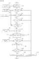
Fig. 2 is a flow chart for DPF regeneration according to an embodiment of the present invention. - Hereinafter, the present invention will be described in detail with reference to the accompanying drawings.
- Although the present invention has been described with reference to the preferred embodiment in the attached figures, it is to be understood that various equivalent modifications and variations of the embodiments can be made by a person having an ordinary skill in the art without departing from the spirit and scope of the present invention as recited in the claims.
- The description not relevant for the present invention has been abbreviated for clarity, and like reference numerals designate like elements throughout the specification. Unless expressed to the contrary, the word "compromise" will be understood to imply the inclusion of stated elements but not exclusion of any other elements.
-
Fig. 1 is a flow chart for DPF regeneration according to the conventional technology. - When an engine is turned on (C12), a condition of start key state is transmitted to E-ECU (Engine ECU). When an exhaust gas is accumulated in DPF and the regeneration of DPF is required (C22), whether or not the regeneration is possible is checked on. If the conditions for regeneration are satisfied, it proceeds right to regeneration step (C60). If not, it proceeds to the step of checking whether the conditions for regeneration are satisfied.
- First, it is checked if a lock-out lever is positioned in the falling edge. (C30). The lock-out lever is a kind of safety lever, and if it is positioned in the falling edge, the equipment or vehicle is put under the state similar to parking, which can be understood to be the condition for the possible regeneration. Then it may proceed to C60.
- If the lock-out lever is not in the position of falling edge, an idle mode is set and an engine rpm and an enine torque are controlled to be kept at the steady levels. (C50)
- When the start key or switch is activated afterwards, the regeneration starts (C50) and the engine rpm is automatically increased to the engine rpm necessary for DPF regeneration (C60).
- If the temperature of the exhaust gas reaches a target temperature, DPF regeneration is carried out successfully. (C80). If not, the regeneration is cancelled (C90).
-
Fig. 2 is a flow chart for DPF regeneration according to an embodiment of the present disclosure. - The initial steps of DPF regeneration according to an embodiment of the present disclosure proceed similarly to those of the DPF regeneration according to the conventional technology. In the conventional technology, the preconditions for the regeneration are checked sequentially, and if any of such conditions is met, DPF regeneration gets started. However, in the present disclosure, if all the individual conditions are not met, the regeneration is cancelled. Thus, since the conventional method is designed to start the DPF regeneration first, the probability of incomplete regeneration is relatively high. So, even if the engine torque does not reach the optimal value for the regeneration, the regeneration may proceed with the unsatisfactory result. In the method according to the present disclosure, the efficient DPF regeneration can be achieved because the regeneration is carried out under the preconditions of the regeneration are fully met.
- In the initial step according to the present disclosure, a key state of engine start (S12) is transmitted to E-ECU. If the regeneration is required, the equipmen or vehicle checks whether or not the regeneration can be carried out (S20). That is, if the regeneration is required due to the accumulated exhaust gas (S22), the possibility of regeneration is checked and the regeneration is cancelled if it turns out that the regeneration is not possible. (S120)
- If it is found out that the DPF regeneration is possible, it is checked if the preconditions of DPF regeneration are met. First, it is checked if the lock-out lever is positioned in the falling edge. (S30). If the lock-out lever is not positioned in the falling edge, it proceeds to the cancellation step. (S120) As described above, the lock-out lever is a kind of safety lever, and if it is positioned in the falling edge, it is meant that the vehicle is kept under the parking state. In other words, if it is found out in S30 that the equipment or vehicle is not able to perform DPF regeneration at the standstill, it proceeds to the cancellation step.
- If the lock-out lever is not in the position of falling edge, an idle mode is set and the engine rpm and torque are controlled to be kept at the steady levels. (S50)
- If the preconditions for DPF regeneration are met, the equipment gets into DPF regeneration mode, and then proceeds to the step of determining hydraulic options for calibrating the engine state to the optimal condition of DPF regeneration. Depending on the hydraulic options, the equipment can make use of either gear pump or main pump. The optimal target value of the engine torque is predetermined by pre-test. In order to match the present engine torque with a target engine torque, the flow rate of gear pump or main pump is controlled. The equipment can increase the flow rate of the hydraulic gear pump or main pump based on the outputs of gear pump and main pump (hydraulic parameters) that are measured at S62. Just in case, both the flow rates of gear pump and main pump can be increased together.
- In the step of increasing the flow rate of gear pump or main pump, the flow rates can be controlled to increase to the predetermined flow rates of gear pump or main pump.
- If the flow rates are increased, the engine torque is increased, and then it proceeds to the step of E-ECU checking if the target engine torque is reached.
- If the target engine torque is reached, DPF regeneration starts (S100). If not, the regeneration is cancelled (S120).
- The engine torque is gradually increased to the target engine torque during the regeneration from the step S100.
- In S110, it is checked if the temperature of exhaust gas reaches the temperature high enough for the regeneration. If the exhaust gas temperature does not reach the target temperature during the regeneration, the regeneration is cancelled (S120) as the condition for regeneration is not considered to be met. On the contrary, if the target temperature is reached, the regeneration is carried out successfully (S130).
- The description above is considered to be only one of exemplary embodiments. The scope of the present invention is not limited to the embodiment described above, but is intended to cover various modifications by those skilled in the art within the scope of the claims of the present invention.
Claims (8)
- An engine torque control method for calibrating an engine torque optimized for DPF regeneration, comprising;a step of entering DPF regeneration mode;a step of detecting outputs of gear pump and main pump as parameters for calibrating conditions of DPF regeneration condition;a step of increasing flow rate of gear pump or main hydraulic pump;a step of controlling an engine torque to reach a predetermined target engine torque value according to the increase of the flow rate of the gear pump or the main hydraulic pump;a step of starting the DPF regeneration if the engine torque reaches the predetermined target engine torque value;a step of increasing an engine rpm based on the predetermined target engine torque value during the DPF regeneration; anda step of carrying out the DPF regeneration until an exhaust gas temperature reaches a predetermined target temperature.
- The engine torque control method of claim 1, further comprising;a step of checking if a vehicle is under a state possible for the DPF regeneration when the DPF regeneration is required; anda step of a checking if a precondition for the DPF regeneration is satisfied, whereinthe DPF regeneration mode gets started if the precondition is satisfied.
- The engine torque control method of claim 2, wherein;the step of a checking if a precondition for the DPF regeneration is satisfied comprises;a step of checking whether or not a control lock-out lever is released; anda step of checking whether or not an idling mode exists.
- The engine torque control method of claim 1, wherein the flow rate of the gear pump or the main hydraulic pump are increased to the predetermined flow rates of the gear pump or the main hydraulic pump in the step of increasing the flow rates of the gear pump or the main hydraulic pump.
- The engine torque control method of claim 3, wherein the DPF regeneration is cancelled if the control lock-out lever is not released, or the idling mode does not exist.
- The engine torque control method of any one of claims 1 to 5, wherein the DPF regeneration is cancelled if the vehicle is not in the state possible for the DPF regeneration in the step of checking if a vehicle is under the state possible for the DPF regeneration when the DPF regeneration is required.
- The engine torque control method of any one of claims 1 to 5, further comprising;
a step of cancelling the regeneration if the engine torque value does not reach a predetermined target engine torque value in the step of controlling the engine torque to reach the predetermined target engine torque value according to the increase of the flow rates of the gear pump or the main hydraulic pump. - The engine torque control method of any one of claims 1 to 5, further comprising;
a step of cancelling the DPF regeneration if the exhaust gas temperature does not reach the predetermined target temperature for the DPF regeneration in the step of carrying out the DPF regeneration when the exhaust gas temperature reaches the predetermined target temperature for the DPF regeneration.
Applications Claiming Priority (1)
| Application Number | Priority Date | Filing Date | Title |
|---|---|---|---|
| PCT/KR2015/001534 WO2016133226A1 (en) | 2015-02-16 | 2015-02-16 | Torque control system for dpf regeneration |
Publications (2)
| Publication Number | Publication Date |
|---|---|
| EP3260690A1 true EP3260690A1 (en) | 2017-12-27 |
| EP3260690A4 EP3260690A4 (en) | 2018-10-17 |
Family
ID=56692538
Family Applications (1)
| Application Number | Title | Priority Date | Filing Date |
|---|---|---|---|
| EP15882760.0A Withdrawn EP3260690A4 (en) | 2015-02-16 | 2015-02-16 | Torque control system for dpf regeneration |
Country Status (4)
| Country | Link |
|---|---|
| US (1) | US10358960B2 (en) |
| EP (1) | EP3260690A4 (en) |
| CN (1) | CN107407218A (en) |
| WO (1) | WO2016133226A1 (en) |
Cited By (1)
| Publication number | Priority date | Publication date | Assignee | Title |
|---|---|---|---|---|
| CN114263544A (en) * | 2021-12-28 | 2022-04-01 | 柳州柳工挖掘机有限公司 | Parking regeneration control method for engineering vehicle |
Families Citing this family (5)
| Publication number | Priority date | Publication date | Assignee | Title |
|---|---|---|---|---|
| CN106593863B (en) * | 2016-10-14 | 2019-07-05 | 上海上汽马瑞利动力总成有限公司 | A kind of gear pump initial torque test method |
| CN109339917A (en) * | 2018-09-30 | 2019-02-15 | 潍柴动力股份有限公司 | Protection method of DPF regeneration |
| CN109882275A (en) * | 2019-03-20 | 2019-06-14 | 苏州国方汽车电子有限公司 | A kind of vehicle motor dpf regeneration control method and device |
| US11274617B1 (en) * | 2020-08-18 | 2022-03-15 | Caterpillar Inc. | System including engine and method of operating engine |
| CN119844225B (en) * | 2025-03-21 | 2025-07-18 | 潍柴动力股份有限公司 | Constant power pump operation regeneration flow control method, system, equipment and storage medium |
Family Cites Families (14)
| Publication number | Priority date | Publication date | Assignee | Title |
|---|---|---|---|---|
| JP4120381B2 (en) * | 2002-12-11 | 2008-07-16 | 日産自動車株式会社 | Filter regeneration control device for diesel engine |
| JP4140371B2 (en) * | 2002-12-16 | 2008-08-27 | 日産自動車株式会社 | Particulate filter regeneration device and engine exhaust gas purification device |
| JP2005256804A (en) * | 2004-03-15 | 2005-09-22 | Denso Corp | Exhaust gas purification device for internal combustion engine |
| JP2006105057A (en) * | 2004-10-07 | 2006-04-20 | Mitsubishi Motors Corp | Diesel engine exhaust purification system |
| JP5122896B2 (en) * | 2007-09-25 | 2013-01-16 | 日立建機株式会社 | Exhaust gas purification system for construction machinery |
| JP5284228B2 (en) * | 2009-09-07 | 2013-09-11 | 本田技研工業株式会社 | Exhaust purification device |
| CN102695929B (en) | 2009-11-18 | 2014-07-30 | 三菱电机株式会社 | Refrigeration cycle device and information transmission method applicable to the refrigeration cycle device |
| KR20120117975A (en) * | 2010-01-28 | 2012-10-25 | 히다찌 겐끼 가부시키가이샤 | Exhaust-gas purification system for hydraulic construction equipment |
| JP5417279B2 (en) * | 2010-07-30 | 2014-02-12 | 株式会社東芝 | Method for producing organic electroluminescence device and solution for organic electroluminescence device |
| JP5548882B2 (en) * | 2010-08-27 | 2014-07-16 | 日立建機株式会社 | Exhaust gas purification system for work vehicles |
| KR101737637B1 (en) * | 2010-12-24 | 2017-05-18 | 두산인프라코어 주식회사 | System and method of active DPF regeneration for construction machinery comprising electro-hydraulic pump |
| US8820057B2 (en) * | 2011-03-30 | 2014-09-02 | Deere & Company | Increased fan speed to assist DPF regeneration |
| KR101953414B1 (en) * | 2011-10-04 | 2019-02-28 | 가부시키가이샤 히다치 겡키 티에라 | Hydraulic drive system used in construction machine and provided with exhaust gas purification device |
| JP6013888B2 (en) * | 2012-11-20 | 2016-10-25 | 株式会社Kcm | Hydraulic drive system and construction machine including the same |
-
2015
- 2015-02-16 EP EP15882760.0A patent/EP3260690A4/en not_active Withdrawn
- 2015-02-16 US US15/550,427 patent/US10358960B2/en active Active
- 2015-02-16 CN CN201580075833.7A patent/CN107407218A/en active Pending
- 2015-02-16 WO PCT/KR2015/001534 patent/WO2016133226A1/en not_active Ceased
Cited By (2)
| Publication number | Priority date | Publication date | Assignee | Title |
|---|---|---|---|---|
| CN114263544A (en) * | 2021-12-28 | 2022-04-01 | 柳州柳工挖掘机有限公司 | Parking regeneration control method for engineering vehicle |
| CN114263544B (en) * | 2021-12-28 | 2023-03-21 | 柳州柳工挖掘机有限公司 | Parking regeneration control method for engineering vehicle |
Also Published As
| Publication number | Publication date |
|---|---|
| US10358960B2 (en) | 2019-07-23 |
| EP3260690A4 (en) | 2018-10-17 |
| WO2016133226A1 (en) | 2016-08-25 |
| US20180023432A1 (en) | 2018-01-25 |
| CN107407218A (en) | 2017-11-28 |
Similar Documents
| Publication | Publication Date | Title |
|---|---|---|
| US10358960B2 (en) | Torque control system for DPF regeneration | |
| US8429904B2 (en) | Working machine | |
| RU2550219C2 (en) | Method and system for regeneration of diesel particulate filter | |
| KR101816430B1 (en) | Control method of exhaust gas purification system | |
| US20120227379A1 (en) | Filter Cleaning With An Engine Idle Bump | |
| US10883409B2 (en) | Method for regenerating exhaust gas filter for vehicle | |
| US20120031080A1 (en) | Method and apparatus for predicting peak temperature in a vehicle particulate filter | |
| JP2011027111A (en) | Method for monitoring hydrocarbon level of diesel particulate filter | |
| CN113661312A (en) | System and method for desulfurization of a catalyst included in an aftertreatment system | |
| KR20180112228A (en) | Method for controlling the regeneration of scr on diesel particular filter | |
| KR101534714B1 (en) | Method of controlling ammonia amount absorbed in selective catalytic reduction catalyst and exhaust system using the same | |
| US8857152B2 (en) | System and method for unloading hydrocarbon emissions from an exhaust after-treatment device | |
| US20170074190A1 (en) | Control method for improving nitrogen oxide purification performance | |
| CN101479457B (en) | Exhaust gas purification system for internal combustion engine | |
| KR102019867B1 (en) | Method for judging the regeneration strategy of the diesel particulate filter with ISG and calculating the amount of soot combustion in a controlled diesel particulate filter | |
| JP2016006311A (en) | Diesel engine exhaust emission control system and diesel engine exhaust emission control method | |
| JP6650675B2 (en) | System for preventing accumulation of unburned hydrocarbons in the lines of exhaust gas aftertreatment systems of internal combustion engines | |
| KR101550621B1 (en) | Method amd system of determining suitability of correction to control logic of selective catalytic reduction catalyst | |
| JP4396760B2 (en) | Exhaust gas purification device for internal combustion engine | |
| CN107131039B (en) | Method for operating an exhaust gas aftertreatment system of a motor vehicle | |
| US12230076B2 (en) | Control device and notification method | |
| JP2008523321A (en) | Protection of oxidation catalyst located upstream of particle filter for diesel engine due to injection fuel limitation | |
| CN110578589B (en) | Method and device for operating an internal combustion engine having a particle filter | |
| CN118234928A (en) | System and method for controlling operation of an exhaust treatment device | |
| CN114207261A (en) | Method and device for controlling the operation of a particle filter of a motor vehicle |
Legal Events
| Date | Code | Title | Description |
|---|---|---|---|
| PUAI | Public reference made under article 153(3) epc to a published international application that has entered the european phase |
Free format text: ORIGINAL CODE: 0009012 |
|
| 17P | Request for examination filed |
Effective date: 20170901 |
|
| AK | Designated contracting states |
Kind code of ref document: A1 Designated state(s): AL AT BE BG CH CY CZ DE DK EE ES FI FR GB GR HR HU IE IS IT LI LT LU LV MC MK MT NL NO PL PT RO RS SE SI SK SM TR |
|
| AX | Request for extension of the european patent |
Extension state: BA ME |
|
| DAX | Request for extension of the european patent (deleted) | ||
| A4 | Supplementary search report drawn up and despatched |
Effective date: 20180917 |
|
| RIC1 | Information provided on ipc code assigned before grant |
Ipc: F02D 41/04 20060101AFI20180911BHEP Ipc: F01N 3/023 20060101ALI20180911BHEP Ipc: F01N 9/00 20060101ALI20180911BHEP Ipc: F02D 41/02 20060101ALI20180911BHEP Ipc: F02D 29/04 20060101ALI20180911BHEP |
|
| STAA | Information on the status of an ep patent application or granted ep patent |
Free format text: STATUS: THE APPLICATION IS DEEMED TO BE WITHDRAWN |
|
| 18D | Application deemed to be withdrawn |
Effective date: 20190416 |