EP3260681A1 - Electric supercharging system and method for controlling electric supercharger - Google Patents
Electric supercharging system and method for controlling electric supercharger Download PDFInfo
- Publication number
- EP3260681A1 EP3260681A1 EP15882559.6A EP15882559A EP3260681A1 EP 3260681 A1 EP3260681 A1 EP 3260681A1 EP 15882559 A EP15882559 A EP 15882559A EP 3260681 A1 EP3260681 A1 EP 3260681A1
- Authority
- EP
- European Patent Office
- Prior art keywords
- electric supercharger
- control unit
- accelerator opening
- electric
- engine
- Prior art date
- Legal status (The legal status is an assumption and is not a legal conclusion. Google has not performed a legal analysis and makes no representation as to the accuracy of the status listed.)
- Granted
Links
Images



Classifications
-
- F—MECHANICAL ENGINEERING; LIGHTING; HEATING; WEAPONS; BLASTING
- F02—COMBUSTION ENGINES; HOT-GAS OR COMBUSTION-PRODUCT ENGINE PLANTS
- F02D—CONTROLLING COMBUSTION ENGINES
- F02D23/00—Controlling engines characterised by their being supercharged
- F02D23/02—Controlling engines characterised by their being supercharged the engines being of fuel-injection type
-
- F—MECHANICAL ENGINEERING; LIGHTING; HEATING; WEAPONS; BLASTING
- F02—COMBUSTION ENGINES; HOT-GAS OR COMBUSTION-PRODUCT ENGINE PLANTS
- F02B—INTERNAL-COMBUSTION PISTON ENGINES; COMBUSTION ENGINES IN GENERAL
- F02B33/00—Engines characterised by provision of pumps for charging or scavenging
- F02B33/32—Engines with pumps other than of reciprocating-piston type
- F02B33/34—Engines with pumps other than of reciprocating-piston type with rotary pumps
- F02B33/40—Engines with pumps other than of reciprocating-piston type with rotary pumps of non-positive-displacement type
-
- F—MECHANICAL ENGINEERING; LIGHTING; HEATING; WEAPONS; BLASTING
- F02—COMBUSTION ENGINES; HOT-GAS OR COMBUSTION-PRODUCT ENGINE PLANTS
- F02B—INTERNAL-COMBUSTION PISTON ENGINES; COMBUSTION ENGINES IN GENERAL
- F02B37/00—Engines characterised by provision of pumps driven at least for part of the time by exhaust
- F02B37/04—Engines with exhaust drive and other drive of pumps, e.g. with exhaust-driven pump and mechanically-driven second pump
-
- F—MECHANICAL ENGINEERING; LIGHTING; HEATING; WEAPONS; BLASTING
- F02—COMBUSTION ENGINES; HOT-GAS OR COMBUSTION-PRODUCT ENGINE PLANTS
- F02B—INTERNAL-COMBUSTION PISTON ENGINES; COMBUSTION ENGINES IN GENERAL
- F02B37/00—Engines characterised by provision of pumps driven at least for part of the time by exhaust
- F02B37/12—Control of the pumps
- F02B37/14—Control of the alternation between or the operation of exhaust drive and other drive of a pump, e.g. dependent on speed
-
- F—MECHANICAL ENGINEERING; LIGHTING; HEATING; WEAPONS; BLASTING
- F02—COMBUSTION ENGINES; HOT-GAS OR COMBUSTION-PRODUCT ENGINE PLANTS
- F02B—INTERNAL-COMBUSTION PISTON ENGINES; COMBUSTION ENGINES IN GENERAL
- F02B39/00—Component parts, details, or accessories relating to, driven charging or scavenging pumps, not provided for in groups F02B33/00 - F02B37/00
- F02B39/02—Drives of pumps; Varying pump drive gear ratio
- F02B39/08—Non-mechanical drives, e.g. fluid drives having variable gear ratio
- F02B39/10—Non-mechanical drives, e.g. fluid drives having variable gear ratio electric
-
- F—MECHANICAL ENGINEERING; LIGHTING; HEATING; WEAPONS; BLASTING
- F02—COMBUSTION ENGINES; HOT-GAS OR COMBUSTION-PRODUCT ENGINE PLANTS
- F02D—CONTROLLING COMBUSTION ENGINES
- F02D23/00—Controlling engines characterised by their being supercharged
-
- F—MECHANICAL ENGINEERING; LIGHTING; HEATING; WEAPONS; BLASTING
- F02—COMBUSTION ENGINES; HOT-GAS OR COMBUSTION-PRODUCT ENGINE PLANTS
- F02D—CONTROLLING COMBUSTION ENGINES
- F02D41/00—Electrical control of supply of combustible mixture or its constituents
- F02D41/0002—Controlling intake air
- F02D41/0007—Controlling intake air for control of turbo-charged or super-charged engines
-
- F—MECHANICAL ENGINEERING; LIGHTING; HEATING; WEAPONS; BLASTING
- F02—COMBUSTION ENGINES; HOT-GAS OR COMBUSTION-PRODUCT ENGINE PLANTS
- F02D—CONTROLLING COMBUSTION ENGINES
- F02D41/00—Electrical control of supply of combustible mixture or its constituents
- F02D41/02—Circuit arrangements for generating control signals
- F02D41/04—Introducing corrections for particular operating conditions
- F02D41/045—Detection of accelerating or decelerating state
-
- F—MECHANICAL ENGINEERING; LIGHTING; HEATING; WEAPONS; BLASTING
- F02—COMBUSTION ENGINES; HOT-GAS OR COMBUSTION-PRODUCT ENGINE PLANTS
- F02D—CONTROLLING COMBUSTION ENGINES
- F02D41/00—Electrical control of supply of combustible mixture or its constituents
- F02D41/02—Circuit arrangements for generating control signals
- F02D41/04—Introducing corrections for particular operating conditions
- F02D41/10—Introducing corrections for particular operating conditions for acceleration
-
- F—MECHANICAL ENGINEERING; LIGHTING; HEATING; WEAPONS; BLASTING
- F02—COMBUSTION ENGINES; HOT-GAS OR COMBUSTION-PRODUCT ENGINE PLANTS
- F02D—CONTROLLING COMBUSTION ENGINES
- F02D2200/00—Input parameters for engine control
- F02D2200/02—Input parameters for engine control the parameters being related to the engine
- F02D2200/10—Parameters related to the engine output, e.g. engine torque or engine speed
- F02D2200/101—Engine speed
-
- F—MECHANICAL ENGINEERING; LIGHTING; HEATING; WEAPONS; BLASTING
- F02—COMBUSTION ENGINES; HOT-GAS OR COMBUSTION-PRODUCT ENGINE PLANTS
- F02D—CONTROLLING COMBUSTION ENGINES
- F02D2200/00—Input parameters for engine control
- F02D2200/02—Input parameters for engine control the parameters being related to the engine
- F02D2200/10—Parameters related to the engine output, e.g. engine torque or engine speed
- F02D2200/1012—Engine speed gradient
-
- F—MECHANICAL ENGINEERING; LIGHTING; HEATING; WEAPONS; BLASTING
- F02—COMBUSTION ENGINES; HOT-GAS OR COMBUSTION-PRODUCT ENGINE PLANTS
- F02D—CONTROLLING COMBUSTION ENGINES
- F02D2200/00—Input parameters for engine control
- F02D2200/60—Input parameters for engine control said parameters being related to the driver demands or status
- F02D2200/602—Pedal position
-
- F—MECHANICAL ENGINEERING; LIGHTING; HEATING; WEAPONS; BLASTING
- F02—COMBUSTION ENGINES; HOT-GAS OR COMBUSTION-PRODUCT ENGINE PLANTS
- F02D—CONTROLLING COMBUSTION ENGINES
- F02D2200/00—Input parameters for engine control
- F02D2200/60—Input parameters for engine control said parameters being related to the driver demands or status
- F02D2200/606—Driving style, e.g. sporty or economic driving
-
- Y—GENERAL TAGGING OF NEW TECHNOLOGICAL DEVELOPMENTS; GENERAL TAGGING OF CROSS-SECTIONAL TECHNOLOGIES SPANNING OVER SEVERAL SECTIONS OF THE IPC; TECHNICAL SUBJECTS COVERED BY FORMER USPC CROSS-REFERENCE ART COLLECTIONS [XRACs] AND DIGESTS
- Y02—TECHNOLOGIES OR APPLICATIONS FOR MITIGATION OR ADAPTATION AGAINST CLIMATE CHANGE
- Y02T—CLIMATE CHANGE MITIGATION TECHNOLOGIES RELATED TO TRANSPORTATION
- Y02T10/00—Road transport of goods or passengers
- Y02T10/10—Internal combustion engine [ICE] based vehicles
- Y02T10/12—Improving ICE efficiencies
Definitions
- the present invention relates to an electric supercharging system and a method for controlling electric supercharger.
- Patent Document 1 Japanese Patent Application Laid-open Publication No. 2007-71137
- Patent Document 1 Japanese Patent Application Laid-open Publication No. 2007-71137
- the present invention aims to provide an electric supercharging system and a method for controlling electric supercharger suppressing the actuation delay of the electric supercharger at an acceleration time.
- the electric supercharging system has an electric supercharger which is disposed on an intake air passage of an engine and a control unit. Then, the control unit changes an actuation timing of the electric supercharger on the basis of change amounts of the rotational speed and the accelerator opening of the engine.
- control unit which controls the electric supercharger which is disposed on the intake air passage of the engine changes the actuation timing of the electric supercharger on the basis of the change amounts of the rotational speed and the accelerator opening of the engine.
- the actuation delay of the electric supercharger at the acceleration time can be suppressed.
- FIG. 1 illustrates one example of an electric supercharging system mounted on a vehicle such as a truck and so forth.
- An air cleaner 130, an electric supercharger 140, a compressor 152 of a turbocharger 150, an intercooler 160 and an intake throttle 170 are disposed in this order in an intake pipe 120 which is connected to an intake manifold 110 of a diesel engine 100 along an intake air flowing direction.
- the engine may be a gasoline engine not limited to the diesel engine 100.
- the intake pipe 120 is given as one example of an intake air passage.
- the air cleaner 130 filters and removes dust and so forth in intake air by an air element.
- the electric supercharger 140 rotationally drives a compressor 144 by an electric motor 142 such as, for example, a blushless motor and so forth and supercharges the intake air from which the dust and so forth have been removed by the air cleaner 130.
- the turbocharger 150 supercharges the intake air by the compressor 152 which is rotationally driven with exhaust energy.
- the intercooler 160 cools the intake air which has passed through the compressor 152 by using, for example, a traveling wind, cooling water.
- the intake throttle 170 suppresses a vibration which would generate when stopping the diesel engine 100 by, for example, choking the intake air when stopping the diesel engine 100.
- the intake pipe 120 of the diesel engine 100 is additionally equipped with a bypass passage 180 which bypasses the compressor 144 of the electric supercharger 140.
- a remote-controllable channel switching valve 190 which at least fully opens and fully closes the intake air passage is disposed in the bypass passage 180.
- the channel switching valve 190 for example, a butterfly valve and so forth whose valve element is rotated by a servomotor and so forth may be used.
- the opening of the channel switching valve 190 when the opening of the channel switching valve 190 is fully opened, the total amount of the intake air which has passed through the air cleaner 130 is not introduced into the compressor 144 of the electric supercharger 140 but is directly introduced into the compressor 152 of the turbocharger 150.
- the opening of the channel switching valve 190 when the opening of the channel switching valve 190 is fully closed, the total amount of the intake air which has passed through the air cleaner 130 is introduced into the compressor 152 of the turbocharger 150 via the compressor 144 of the electric supercharger 140.
- the channel switching valve 190 when the channel switching valve 190 is brought to have an intermediate opening between full-open and full-close, the intake air which has passed through the air cleaner 130 is branched into the compressor 144 of the electric supercharger 140 and the compressor 152 of the turbocharger 150 in accordance with the opening of the channel switching valve 190.
- a turbine 154 of the turbocharger 150 and an exhaust purification device are disposed in an exhaust pipe 210 which is connected to an exhaust manifold 200 of the diesel engine 100 along an exhaust air flowing direction.
- the turbine 154 of the turbocharger 150 is rotationally driven with exhaust air which flows through the exhaust pipe 210 and rotationally drives the compressor 152 which is coupled thereto via a not illustrated shaft.
- the exhaust purification device selectively purifies a nitrogen oxide in the exhaust air by using, for example, an aqueous solution of urea as a reducing agent precursor.
- a constant-mesh transmission 230 is attached to an output shaft of the diesel engine 100 via a clutch or a torque converter (not illustrated) and a motor generator 220.
- An output shaft of the transmission 230 is coupled to one pair of left and right rear wheels 260 as drive wheels via a propeller shaft 240 and a differential carrier 250.
- the motor generator 220 may be attached also in parallel with, for example, the transmission 230.
- an energy storage system (ESS) 270 which supplies drive power to the electric motor 142 of the electric supercharger 140 and the motor generator 220 and stores electric power generated by the electric motor 142 and the motor generator 220 is mounted on a predetermined place of the vehicle.
- the energy storage system 270 is connected to be communicable with an electronic control unit 290 in which a microcomputer is built via an on-vehicle network 280 such as, for example, CAN (Controller Area Network) and so forth.
- the electronic control unit 290 is given as one example of the control unit.
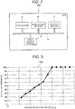
- the electronic control unit 290 has a processor A such as a CPU (Central Processing Unit) and so forth, a nonvolatile memory B such as a flash ROM (Read Only Memory) and so forth, a volatile memory C such as a RAM (Random Access Memory) and so forth, an input/output circuit D which serves as an interface with outer equipment, and a bus E which communicably connects them together as illustrated in FIG. 2 .
- a processor A such as a CPU (Central Processing Unit) and so forth
- a nonvolatile memory B such as a flash ROM (Read Only Memory) and so forth
- a volatile memory C such as a RAM (Random Access Memory) and so forth
- an input/output circuit D which serves as an interface with outer equipment
- a bus E which communicably connects them together as illustrated in FIG. 2 .
- Respective output signals from a rotational speed sensor 300 which detects a rotational speed Ne of the diesel engine 100 and from an accelerator opening sensor 310 which detects an opening (an accelerator opening) ACC of a not illustrated accelerator pedal are input into the electronic control unit 290.
- the rotational speed Ne and the accelerator opening ACC may be also read out of, for example, an electronic control unit (not illustrated) of the diesel engine 100 which is connected via the on-vehicle network 280.
- the electronic control unit 290 outputs control signals respectively to the channel switching valve 190 and the energy storage system 270 on the basis of the respective output signals from the rotational speed sensor 300 and the accelerator opening sensor 310 and electronically controls actuation and stop of the electric supercharger 140.
- An actuation opening map 292 illustrated in FIG. 3 , a stop opening map 294 illustrated in FIG. 4 and a correction coefficient map 296 illustrated in FIG. 5 are respectively stored in the nonvolatile memory B of the electronic control unit 290.
- the actuation opening map 292 is a map for defining a timing at which the electric supercharger 140 is actuated at a steady-state operation time and an actuation opening (an accelerator opening) according to the engine rotational speed is set therein as illustrated in FIG. 3 .
- the actuation opening is increased little by little (gradually increased) as the engine rotational speed is increased and the actuation opening becomes 100% (full-open) after reaching a certain engine rotational speed. Accordingly, it can be grasped from this actuation opening map 292 that when the engine rotational speed is low, the actuation timing is advanced and when the engine rotational speed is high, the actuation timing is delayed.
- the actuation opening map 292 is obtained from an engine characteristic map illustrated in FIG. 6 , that is, the map in which an actuation region and a stop region of the electric supercharger 140 is demarcated in a full-load region of the diesel engine 100 by taking the accelerator opening into consideration.
- the stop opening map 294 is a map for defining a timing at which the electric supercharger 140 is stopped. As illustrated in FIG. 4 , a stop opening (the accelerator opening) according to the engine rotational speed is set in the stop opening map 294.
- the stop opening map 294 is, for example, a map that predetermined hysteresis (-5%) is given to the actuation opening map 292 in order to suppress hunching and so forth. Accordingly, the stop opening map 294 has a characteristic which is similar to that of the actuation opening map.
- the correction coefficient map 296 is a map for defining a correction coefficient (a coefficient) used for correcting the actuation timing at the steady-state operation time, at a transient operation time such as at an acceleration time and so forth and the correction coefficient according to a change amount of the accelerator opening is set as illustrated in FIG. 5 .
- the correction coefficient has a value which is larger than 0.0 and is equal to or less than 1.0 so as to advance the actuation timing as needed in order to suppress an actuation delay of the electric supercharger 140 at the transient operation time and is decreased little by little (gradually decreased) as the change amount of the accelerator opening is increased.
- the correction coefficient map 296 is acquired by obtaining an optimum correction coefficient through, for example, experiments and so forth for each of a plurality of acceleration states according to a change rate of the accelerator opening and plotting (see a broken line) it on the map as illustrated in FIG. 7 .
- the electronic control unit 290 obtains an actuation opening START_ACC at the steady-state operation time according to the rotational speed Ne with reference to the actuation opening map 292 as illustrated in FIG. 8 .
- the electronic control unit 290 monitors the accelerator opening ACC and obtains, for example, an accelerator opening change amount TRN_ACC per unit time.
- the electronic control unit 290 obtains a correction coefficient K_TRN_ACC according to the accelerator opening change amount TRN_ACC with reference to the correction coefficient map 296.
- the electronic control unit 290 obtains an actuation timing START_ACC_eSC of the electric supercharger 140 that a transient state is taken into consideration by multiplying the actuation opening START_ACC at the steady-state operation time and the correction coefficient K_TRN_ACC. Then, when the accelerator opening ACC becomes larger than the actuation timing START_ACC_eSC, the electronic control unit 290 actuates the electric supercharger 140.
- the electronic control unit 290 outputs the control signal to the channel switching valve 190 and introduces the total amount of the intake air which has passed through the air cleaner 130 into the electric supercharger 140.
- the electronic control unit 290 After the electric supercharger 140 has been actuated, the electronic control unit 290 obtains a stop opening STOP_ACC according to the rotational speed Ne with reference to the stop opening map 294. Then, when the accelerator opening ACC becomes larger than the actuation opening START_ACC and thereafter the accelerator opening ACC becomes less than the stop opening STOP_ACC, the electronic control unit 290 stops the electric supercharger 140. In short, when the accelerator opening ACC exceeds the actuation opening START_ACC according to the rotational speed Ne and thereafter the accelerator opening ACC becomes less than the stop opening STOP_ACC according to the rotational speed Ne, the electronic control unit 290 stops the electric supercharger 140. Here, when the electric supercharger 140 is to be stopped, the electronic control unit 290 outputs the control signal to the channel switching valve 190 and introduces the total amount of the intake air which has passed through the air cleaner 130 directly into the turbocharger 150.
- the electronic control unit 290 is also able to assist the torque by the motor generator 220 by appropriately controlling the energy storage system 270.
- the electronic control unit 290 is able to store the electric power generated by the electric motor 142 and the motor generator 220 into the energy storage system 270 by appropriately controlling the channel switching valve 190 and the energy storage system 270.
- the electronic control unit 290 is able to control an electric power generation amount of the electric motor 142 by setting the channel switching valve 190 to the intermediate opening.
- FIG. 9 and FIG. 10 illustrate a control program for the electric supercharger 140 that the processor A of the electronic control unit 290 repetitively executes with starting-up of the electronic control unit 290 as a trigger.
- the control program for the electric supercharger 140 is stored in advance in, for example, the nonvolatile memory B of the electronic control unit 290.
- step 1 abbreviated as "S1" in the drawing. The same applies hereafter.
- the processor A of the electronic control unit 290 reads the rotational speed Ne out of the rotational speed sensor 300.
- step 2 the processor A of the electronic control unit 290 obtains the actuation opening START_ACC according to the rotational speed Ne with reference to the actuation opening map 292 ( FIG. 3 ) stored in the nonvolatile memory B.
- step 3 the processor A of the electronic control unit 290 reads the accelerator opening ACC out of the accelerator opening sensor 310.
- step 4 the processor A of the electronic control unit 290 obtains the accelerator opening change amount TRN_ACC per unit time from, for example, a change state of the accelerator opening ACC.
- step 5 the processor A of the electronic control unit 290 obtains the correction coefficient K_TRN_ACC according to the accelerator opening change amount TRN_ACC with reference to the correction coefficient map 296 ( FIG. 5 ) stored in the nonvolatile memory B.
- the processor A of the electronic control unit 290 corrects the actuation opening START_ACC according to the rotational speed Ne with the correction coefficient K_TRN_ACC according to the accelerator opening change amount TRN_ACC.
- step 7 the processor A of the electronic control unit 290 determines whether the accelerator opening ACC is larger than the actuation opening START_ACC_eSC. Then, when the processor A of the electronic control unit 290 determines that the accelerator opening ACC is larger than the actuation opening START_ACC_eSC (Yes), it advances the process to step 8. On the other hand, when the processor A of the electronic control unit 290 determines that the accelerator opening ACC is equal to or less than the actuation opening START_ACC_eSC (No), it returns the process to step 1.
- step 8 the processor A of the electronic control unit 290 actuates the electric supercharger 140. Specifically, the processor A of the electronic control unit 290 outputs an actuation signal to the channel switching valve 190 and introduces the total amount of the intake air which has passed through the air cleaner 130 into the electric supercharger 140. In addition, the processor A of the electronic control unit 290 outputs the actuation signal to the energy storage system 270 so as to actuate the electric motor 142 of the electric supercharger 140. When the electric motor 142 is actuated, the compressor 144 rotationally drives and supercharging of the intake air is started.
- step 9 the processor A of the electronic control unit 290 reads the rotational speed Ne out of the rotational speed sensor 300.
- step 10 the processor A of the electronic control unit 290 reads the accelerator opening ACC out of the accelerator opening sensor 310.
- step 11 the processor A of the electronic control unit 290 obtains the actuation opening START_ACC according to the rotational speed Ne with reference to the actuation opening map 292 ( FIG. 3 ) stored in the nonvolatile memory B.
- the actuation opening START_ACC is given as one example of a first predetermined value which defines the actuation timing according to the rotational speed of the engine.
- step 12 the processor A of the electronic control unit 290 determines whether the accelerator opening ACC is larger than the actuation opening START_ACC. Then, when the processor A of the electronic control unit 290 determines that the accelerator opening ACC is larger than the actuation opening START_ACC (Yes), it advances the process to step 13. On the other hand, when the processor A of the electronic control unit 290 determines that the accelerator opening ACC is equal to or less than the actuation opening START_ACC (No), it returns the process to step 9.
- step 13 the processor A of the electronic control unit 290 reads the rotational speed Ne out of the rotational speed sensor 300.
- step 14 the processor A of the electronic control unit 290 reads the accelerator opening ACC out of the accelerator opening sensor 310.
- step 15 the processor A of the electronic control unit 290 obtains the stop opening STOP_ACC for stopping the electric supercharger 140 according to the rotational speed Ne with reference to the stop opening map 294 ( FIG. 4 ) stored in the nonvolatile memory B.
- the stop opening STOP_ACC is given as one example of a second predetermined value for defining a stop timing according to the rotational speed of the engine.
- step 16 the processor A of the electronic control unit 290 determines whether the accelerator opening ACC is less than the stop opening STOP_ACC. Then, when the processor A of the electronic control unit 290 determines that the accelerator opening ACC is less than the stop opening STOP_ACC (Yes), it advances the process to step 17. On the other hand, when the processor A of the electronic control unit 290 determines that the accelerator opening ACC is equal to or larger than the stop opening STOP_ACC (No), it returns the process to step 13.
- step 17 the processor A of the electronic control unit 290 stops the electric supercharger 140. Specifically, the processor A of the electronic control unit 290 outputs the actuation signal to the channel switching valve 190 and introduces the total amount of the intake air which has passed through the air cleaner 130 into the turbocharger 150. In addition, the processor A of the electronic control unit 290 outputs the actuation signal to the energy storage system 270 so as to stop the electric motor 142 of the electric supercharger 140. At this time, the processor A of the electronic control unit 290 is able to store the electric power that the electric motor 142 has generated until it is stopped into the energy storage system 270 by appropriately controlling the energy storage system 270.
- the electric supercharger 140 when the electric supercharger 140 is not actuated, the total amount of the intake air which has passed through the air cleaner 130 is introduced into the compressor 152 of the turbocharger 150 and it is supercharged by utilizing exhaust air energy. Then, for example, when an accelerator pedal is stepped on for acceleration of the vehicle, required torque is increased with increasing the accelerator opening ACC and the turbocharger 150 becomes unable to cope with it alone and the electric supercharger 140 is actuated.
- the electric supercharger 140 When the electric supercharger 140 is actuated, the intake air which has been supercharged therein is introduced into the compressor 152 of the turbocharger 150 and therefore a response speed of the turbocharger 150 is improved and a so-called turbo lag can be reduced.
- the actuation timing of the electric supercharger 140 is changed by correcting the actuation opening START_ACC at the steady-state operation time according to the engine rotational speed Ne with the correction coefficient K_TRN_ACC according to the accelerator opening change amount TRA_ACC. Therefore, the actuation timing of the electric supercharger 140 can be advanced by appropriately setting the correction coefficient K_TRN_ACC and, in particular, the actuation delay of the electric supercharger 140 at the acceleration time can be suppressed. Then, when the actuation delay of the electric supercharger 140 is suppressed, the torque is increased in conjunction with a change in accelerator opening ACC and, for example, the drivability can be improved.
- the stop determination condition for the electric supercharger 140 is established and therefore hunching can be suppressed even when a difference between the actuation opening START_ACC_eSC and the stop opening STOP_ACC is small.
- the condition for stopping the electric supercharger 140 is able to use the stop opening STOP_ACC at the steady-state operation time, the electric supercharger 140 comes to a stop earlier than usual at a deceleration time and power consumption of the electric supercharger 140 can be suppressed.
- the motor generator 220 or the turbocharger 150 is not necessarily required.
Landscapes
- Engineering & Computer Science (AREA)
- Chemical & Material Sciences (AREA)
- Combustion & Propulsion (AREA)
- Mechanical Engineering (AREA)
- General Engineering & Computer Science (AREA)
- Output Control And Ontrol Of Special Type Engine (AREA)
- Supercharger (AREA)
Abstract
Description
- The present invention relates to an electric supercharging system and a method for controlling electric supercharger.
- In the electric supercharging system, whether it is in a supercharge region has been determined on the basis of an engine rotational speed and an accelerator opening and an electric supercharger has been controlled in accordance with a result of determination as described in Japanese Patent Application Laid-open Publication No.
2007-71137 - Patent Document 1: Japanese Patent Application Laid-open Publication No.
2007-71137 - However, in a case where whether it is in the supercharge region was determined on the basis of the engine rotational speed and the accelerator opening, an acceleration state in which the accelerator opening is rapidly increased is not taken into consideration and therefore there was a possibility that a delay would occur in actuation of the electric supercharger. When the delay occurs in actuation of the electric supercharger, torque is not increased in conjunction with a change in accelerator opening and, for example, drivability is lowered.
- Therefore, the present invention aims to provide an electric supercharging system and a method for controlling electric supercharger suppressing the actuation delay of the electric supercharger at an acceleration time.
- For this purpose, the electric supercharging system has an electric supercharger which is disposed on an intake air passage of an engine and a control unit. Then, the control unit changes an actuation timing of the electric supercharger on the basis of change amounts of the rotational speed and the accelerator opening of the engine.
- In addition, in the method for controlling electric supercharger, the control unit which controls the electric supercharger which is disposed on the intake air passage of the engine changes the actuation timing of the electric supercharger on the basis of the change amounts of the rotational speed and the accelerator opening of the engine.
- According to the present invention, the actuation delay of the electric supercharger at the acceleration time can be suppressed.
-
-
FIG. 1 is an outline diagram illustrating one example of an electric supercharging system. -
FIG. 2 is a functional block diagram illustrating one example of an electronic control unit. -
FIG. 3 is an explanatory diagram illustrating one example of an actuation opening map. -
FIG. 4 is an explanatory diagram illustrating one example of a stop opening map. -
FIG. 5 is an explanatory diagram illustrating one example of a correction coefficient map. -
FIG. 6 is an explanatory diagram illustrating one example of an engine characteristic map. -
FIG. 7 is an explanatory diagram of a state where an optimum correction coefficient is obtained in a plurality of acceleration states. -
FIG. 8 is a functional block diagram illustrating one example of a function of controlling an electric supercharger. -
FIG. 9 is a flowchart illustrating one example of a control program for the electric supercharger. -
FIG. 10 is a flowchart illustrating one example of the control program for the electric supercharger. -
FIG. 11 is an explanatory diagram of a process of stopping the electric supercharger. - In the following, an embodiment for carrying out the present invention will be described in detail with reference to the appended drawings.
-
FIG. 1 illustrates one example of an electric supercharging system mounted on a vehicle such as a truck and so forth. - An
air cleaner 130, anelectric supercharger 140, acompressor 152 of aturbocharger 150, anintercooler 160 and anintake throttle 170 are disposed in this order in anintake pipe 120 which is connected to anintake manifold 110 of adiesel engine 100 along an intake air flowing direction. Incidentally, the engine may be a gasoline engine not limited to thediesel engine 100. Here, theintake pipe 120 is given as one example of an intake air passage. - The air cleaner 130 filters and removes dust and so forth in intake air by an air element. The
electric supercharger 140 rotationally drives acompressor 144 by anelectric motor 142 such as, for example, a blushless motor and so forth and supercharges the intake air from which the dust and so forth have been removed by theair cleaner 130. Theturbocharger 150 supercharges the intake air by thecompressor 152 which is rotationally driven with exhaust energy. Theintercooler 160 cools the intake air which has passed through thecompressor 152 by using, for example, a traveling wind, cooling water. Theintake throttle 170 suppresses a vibration which would generate when stopping thediesel engine 100 by, for example, choking the intake air when stopping thediesel engine 100. - The
intake pipe 120 of thediesel engine 100 is additionally equipped with abypass passage 180 which bypasses thecompressor 144 of theelectric supercharger 140. A remote-controllablechannel switching valve 190 which at least fully opens and fully closes the intake air passage is disposed in thebypass passage 180. Here, as thechannel switching valve 190, for example, a butterfly valve and so forth whose valve element is rotated by a servomotor and so forth may be used. - Accordingly, when the opening of the
channel switching valve 190 is fully opened, the total amount of the intake air which has passed through theair cleaner 130 is not introduced into thecompressor 144 of theelectric supercharger 140 but is directly introduced into thecompressor 152 of theturbocharger 150. On the other hand, when the opening of thechannel switching valve 190 is fully closed, the total amount of the intake air which has passed through theair cleaner 130 is introduced into thecompressor 152 of theturbocharger 150 via thecompressor 144 of theelectric supercharger 140. Here, when thechannel switching valve 190 is brought to have an intermediate opening between full-open and full-close, the intake air which has passed through theair cleaner 130 is branched into thecompressor 144 of theelectric supercharger 140 and thecompressor 152 of theturbocharger 150 in accordance with the opening of thechannel switching valve 190. - A
turbine 154 of theturbocharger 150 and an exhaust purification device (not illustrated) are disposed in anexhaust pipe 210 which is connected to anexhaust manifold 200 of thediesel engine 100 along an exhaust air flowing direction. Theturbine 154 of theturbocharger 150 is rotationally driven with exhaust air which flows through theexhaust pipe 210 and rotationally drives thecompressor 152 which is coupled thereto via a not illustrated shaft. The exhaust purification device selectively purifies a nitrogen oxide in the exhaust air by using, for example, an aqueous solution of urea as a reducing agent precursor. - For example, a constant-
mesh transmission 230 is attached to an output shaft of thediesel engine 100 via a clutch or a torque converter (not illustrated) and amotor generator 220. An output shaft of thetransmission 230 is coupled to one pair of left and rightrear wheels 260 as drive wheels via apropeller shaft 240 and adifferential carrier 250. Incidentally, themotor generator 220 may be attached also in parallel with, for example, thetransmission 230. - In addition, an energy storage system (ESS) 270 which supplies drive power to the
electric motor 142 of theelectric supercharger 140 and themotor generator 220 and stores electric power generated by theelectric motor 142 and themotor generator 220 is mounted on a predetermined place of the vehicle. Theenergy storage system 270 is connected to be communicable with anelectronic control unit 290 in which a microcomputer is built via an on-vehicle network 280 such as, for example, CAN (Controller Area Network) and so forth. Here, theelectronic control unit 290 is given as one example of the control unit. - The
electronic control unit 290 has a processor A such as a CPU (Central Processing Unit) and so forth, a nonvolatile memory B such as a flash ROM (Read Only Memory) and so forth, a volatile memory C such as a RAM (Random Access Memory) and so forth, an input/output circuit D which serves as an interface with outer equipment, and a bus E which communicably connects them together as illustrated inFIG. 2 . - Respective output signals from a
rotational speed sensor 300 which detects a rotational speed Ne of thediesel engine 100 and from anaccelerator opening sensor 310 which detects an opening (an accelerator opening) ACC of a not illustrated accelerator pedal are input into theelectronic control unit 290. Incidentally, the rotational speed Ne and the accelerator opening ACC may be also read out of, for example, an electronic control unit (not illustrated) of thediesel engine 100 which is connected via the on-vehicle network 280. - The
electronic control unit 290 outputs control signals respectively to thechannel switching valve 190 and theenergy storage system 270 on the basis of the respective output signals from therotational speed sensor 300 and theaccelerator opening sensor 310 and electronically controls actuation and stop of theelectric supercharger 140. - An
actuation opening map 292 illustrated inFIG. 3 , astop opening map 294 illustrated inFIG. 4 and acorrection coefficient map 296 illustrated inFIG. 5 are respectively stored in the nonvolatile memory B of theelectronic control unit 290. - The actuation opening
map 292 is a map for defining a timing at which theelectric supercharger 140 is actuated at a steady-state operation time and an actuation opening (an accelerator opening) according to the engine rotational speed is set therein as illustrated inFIG. 3 . In the illustratedactuation opening map 292, the actuation opening is increased little by little (gradually increased) as the engine rotational speed is increased and the actuation opening becomes 100% (full-open) after reaching a certain engine rotational speed. Accordingly, it can be grasped from this actuation openingmap 292 that when the engine rotational speed is low, the actuation timing is advanced and when the engine rotational speed is high, the actuation timing is delayed. Incidentally, the actuation openingmap 292 is obtained from an engine characteristic map illustrated inFIG. 6 , that is, the map in which an actuation region and a stop region of theelectric supercharger 140 is demarcated in a full-load region of thediesel engine 100 by taking the accelerator opening into consideration. - The stop opening
map 294 is a map for defining a timing at which theelectric supercharger 140 is stopped. As illustrated inFIG. 4 , a stop opening (the accelerator opening) according to the engine rotational speed is set in thestop opening map 294. Thestop opening map 294 is, for example, a map that predetermined hysteresis (-5%) is given to theactuation opening map 292 in order to suppress hunching and so forth. Accordingly, thestop opening map 294 has a characteristic which is similar to that of the actuation opening map. - The
correction coefficient map 296 is a map for defining a correction coefficient (a coefficient) used for correcting the actuation timing at the steady-state operation time, at a transient operation time such as at an acceleration time and so forth and the correction coefficient according to a change amount of the accelerator opening is set as illustrated inFIG. 5 . The correction coefficient has a value which is larger than 0.0 and is equal to or less than 1.0 so as to advance the actuation timing as needed in order to suppress an actuation delay of theelectric supercharger 140 at the transient operation time and is decreased little by little (gradually decreased) as the change amount of the accelerator opening is increased. Incidentally, thecorrection coefficient map 296 is acquired by obtaining an optimum correction coefficient through, for example, experiments and so forth for each of a plurality of acceleration states according to a change rate of the accelerator opening and plotting (see a broken line) it on the map as illustrated inFIG. 7 . - The
electronic control unit 290 obtains an actuation opening START_ACC at the steady-state operation time according to the rotational speed Ne with reference to theactuation opening map 292 as illustrated inFIG. 8 . Theelectronic control unit 290 monitors the accelerator opening ACC and obtains, for example, an accelerator opening change amount TRN_ACC per unit time. In addition, theelectronic control unit 290 obtains a correction coefficient K_TRN_ACC according to the accelerator opening change amount TRN_ACC with reference to thecorrection coefficient map 296. Further, theelectronic control unit 290 obtains an actuation timing START_ACC_eSC of theelectric supercharger 140 that a transient state is taken into consideration by multiplying the actuation opening START_ACC at the steady-state operation time and the correction coefficient K_TRN_ACC. Then, when the accelerator opening ACC becomes larger than the actuation timing START_ACC_eSC, theelectronic control unit 290 actuates theelectric supercharger 140. Here, when theelectric supercharger 140 is to be actuated, theelectronic control unit 290 outputs the control signal to thechannel switching valve 190 and introduces the total amount of the intake air which has passed through theair cleaner 130 into theelectric supercharger 140. - After the
electric supercharger 140 has been actuated, theelectronic control unit 290 obtains a stop opening STOP_ACC according to the rotational speed Ne with reference to thestop opening map 294. Then, when the accelerator opening ACC becomes larger than the actuation opening START_ACC and thereafter the accelerator opening ACC becomes less than the stop opening STOP_ACC, theelectronic control unit 290 stops theelectric supercharger 140. In short, when the accelerator opening ACC exceeds the actuation opening START_ACC according to the rotational speed Ne and thereafter the accelerator opening ACC becomes less than the stop opening STOP_ACC according to the rotational speed Ne, theelectronic control unit 290 stops theelectric supercharger 140. Here, when theelectric supercharger 140 is to be stopped, theelectronic control unit 290 outputs the control signal to thechannel switching valve 190 and introduces the total amount of the intake air which has passed through theair cleaner 130 directly into theturbocharger 150. - Incidentally, when engine torque according to the rotational speed Ne and the accelerator opening ACC cannot be exhibited even though the
electric supercharger 140 is actuated, theelectronic control unit 290 is also able to assist the torque by themotor generator 220 by appropriately controlling theenergy storage system 270. In addition, for example, when there is a margin in the engine torque, theelectronic control unit 290 is able to store the electric power generated by theelectric motor 142 and themotor generator 220 into theenergy storage system 270 by appropriately controlling thechannel switching valve 190 and theenergy storage system 270. At this time, theelectronic control unit 290 is able to control an electric power generation amount of theelectric motor 142 by setting thechannel switching valve 190 to the intermediate opening. -
FIG. 9 andFIG. 10 illustrate a control program for theelectric supercharger 140 that the processor A of theelectronic control unit 290 repetitively executes with starting-up of theelectronic control unit 290 as a trigger. Here, the control program for theelectric supercharger 140 is stored in advance in, for example, the nonvolatile memory B of theelectronic control unit 290. - In step 1 (abbreviated as "S1" in the drawing. The same applies hereafter.), the processor A of the
electronic control unit 290 reads the rotational speed Ne out of therotational speed sensor 300. - In step 2, the processor A of the
electronic control unit 290 obtains the actuation opening START_ACC according to the rotational speed Ne with reference to the actuation opening map 292 (FIG. 3 ) stored in the nonvolatile memory B. - In
step 3, the processor A of theelectronic control unit 290 reads the accelerator opening ACC out of theaccelerator opening sensor 310. - In step 4, the processor A of the
electronic control unit 290 obtains the accelerator opening change amount TRN_ACC per unit time from, for example, a change state of the accelerator opening ACC. - In
step 5, the processor A of theelectronic control unit 290 obtains the correction coefficient K_TRN_ACC according to the accelerator opening change amount TRN_ACC with reference to the correction coefficient map 296 (FIG. 5 ) stored in the nonvolatile memory B. - In
step 6, the processor A of theelectronic control unit 290 obtains the actuation opening START_ACC_eSC of theelectric supercharger 140 that the transient state is taken into consideration by multiplying the actuation opening START_ACC and the correction coefficient K_TRN_ACC (START_ACC_eSC = START_ACC x K_TRN_ACC). In short, the processor A of theelectronic control unit 290 corrects the actuation opening START_ACC according to the rotational speed Ne with the correction coefficient K_TRN_ACC according to the accelerator opening change amount TRN_ACC. - In step 7, the processor A of the
electronic control unit 290 determines whether the accelerator opening ACC is larger than the actuation opening START_ACC_eSC. Then, when the processor A of theelectronic control unit 290 determines that the accelerator opening ACC is larger than the actuation opening START_ACC_eSC (Yes), it advances the process to step 8. On the other hand, when the processor A of theelectronic control unit 290 determines that the accelerator opening ACC is equal to or less than the actuation opening START_ACC_eSC (No), it returns the process to step 1. - In step 8, the processor A of the
electronic control unit 290 actuates theelectric supercharger 140. Specifically, the processor A of theelectronic control unit 290 outputs an actuation signal to thechannel switching valve 190 and introduces the total amount of the intake air which has passed through theair cleaner 130 into theelectric supercharger 140. In addition, the processor A of theelectronic control unit 290 outputs the actuation signal to theenergy storage system 270 so as to actuate theelectric motor 142 of theelectric supercharger 140. When theelectric motor 142 is actuated, thecompressor 144 rotationally drives and supercharging of the intake air is started. - In step 9, the processor A of the
electronic control unit 290 reads the rotational speed Ne out of therotational speed sensor 300. - In
step 10, the processor A of theelectronic control unit 290 reads the accelerator opening ACC out of theaccelerator opening sensor 310. - In
step 11, the processor A of theelectronic control unit 290 obtains the actuation opening START_ACC according to the rotational speed Ne with reference to the actuation opening map 292 (FIG. 3 ) stored in the nonvolatile memory B. Here, the actuation opening START_ACC is given as one example of a first predetermined value which defines the actuation timing according to the rotational speed of the engine. - In
step 12, the processor A of theelectronic control unit 290 determines whether the accelerator opening ACC is larger than the actuation opening START_ACC. Then, when the processor A of theelectronic control unit 290 determines that the accelerator opening ACC is larger than the actuation opening START_ACC (Yes), it advances the process to step 13. On the other hand, when the processor A of theelectronic control unit 290 determines that the accelerator opening ACC is equal to or less than the actuation opening START_ACC (No), it returns the process to step 9. - In
step 13, the processor A of theelectronic control unit 290 reads the rotational speed Ne out of therotational speed sensor 300. - In step 14, the processor A of the
electronic control unit 290 reads the accelerator opening ACC out of theaccelerator opening sensor 310. - In
step 15, the processor A of theelectronic control unit 290 obtains the stop opening STOP_ACC for stopping theelectric supercharger 140 according to the rotational speed Ne with reference to the stop opening map 294 (FIG. 4 ) stored in the nonvolatile memory B. Here, the stop opening STOP_ACC is given as one example of a second predetermined value for defining a stop timing according to the rotational speed of the engine. - In step 16, the processor A of the
electronic control unit 290 determines whether the accelerator opening ACC is less than the stop opening STOP_ACC. Then, when the processor A of theelectronic control unit 290 determines that the accelerator opening ACC is less than the stop opening STOP_ACC (Yes), it advances the process to step 17. On the other hand, when the processor A of theelectronic control unit 290 determines that the accelerator opening ACC is equal to or larger than the stop opening STOP_ACC (No), it returns the process to step 13. - In
step 17, the processor A of theelectronic control unit 290 stops theelectric supercharger 140. Specifically, the processor A of theelectronic control unit 290 outputs the actuation signal to thechannel switching valve 190 and introduces the total amount of the intake air which has passed through theair cleaner 130 into theturbocharger 150. In addition, the processor A of theelectronic control unit 290 outputs the actuation signal to theenergy storage system 270 so as to stop theelectric motor 142 of theelectric supercharger 140. At this time, the processor A of theelectronic control unit 290 is able to store the electric power that theelectric motor 142 has generated until it is stopped into theenergy storage system 270 by appropriately controlling theenergy storage system 270. - According to such an electric supercharging system, when the
electric supercharger 140 is not actuated, the total amount of the intake air which has passed through theair cleaner 130 is introduced into thecompressor 152 of theturbocharger 150 and it is supercharged by utilizing exhaust air energy. Then, for example, when an accelerator pedal is stepped on for acceleration of the vehicle, required torque is increased with increasing the accelerator opening ACC and theturbocharger 150 becomes unable to cope with it alone and theelectric supercharger 140 is actuated. When theelectric supercharger 140 is actuated, the intake air which has been supercharged therein is introduced into thecompressor 152 of theturbocharger 150 and therefore a response speed of theturbocharger 150 is improved and a so-called turbo lag can be reduced. - At this time, the actuation timing of the
electric supercharger 140 is changed by correcting the actuation opening START_ACC at the steady-state operation time according to the engine rotational speed Ne with the correction coefficient K_TRN_ACC according to the accelerator opening change amount TRA_ACC. Therefore, the actuation timing of theelectric supercharger 140 can be advanced by appropriately setting the correction coefficient K_TRN_ACC and, in particular, the actuation delay of theelectric supercharger 140 at the acceleration time can be suppressed. Then, when the actuation delay of theelectric supercharger 140 is suppressed, the torque is increased in conjunction with a change in accelerator opening ACC and, for example, the drivability can be improved. - On the other hand, when the accelerator opening ACC exceeds the actuation opening START_ACC as illustrated in
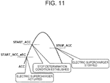
FIG. 11 after actuation of theelectric supercharger 140, a stop determination condition for starting determination of whether a condition for stopping theelectric supercharger 140 has been established is established. Then, when the accelerator opening ACC becomes less than the stop opening STOP_ACC according to the engine rotational speed Ne after establishment of the stop determination condition, theelectric supercharger 140 is stopped. When theelectric supercharger 140 is brought to a stop, the electric power generated in theelectric motor 142 of theelectric supercharger 140 and themotor generator 220 can be stored into theenergy storage system 270 by appropriately controlling thechannel switching valve 190 and theenergy storage system 270 and thereby fuel efficiency of thediesel engine 100 can be improved. - In addition, when the accelerator opening ACC exceeds the actuation opening START_ACC after actuation of the
electric supercharger 140, the stop determination condition for theelectric supercharger 140 is established and therefore hunching can be suppressed even when a difference between the actuation opening START_ACC_eSC and the stop opening STOP_ACC is small. In addition, since the condition for stopping theelectric supercharger 140 is able to use the stop opening STOP_ACC at the steady-state operation time, theelectric supercharger 140 comes to a stop earlier than usual at a deceleration time and power consumption of theelectric supercharger 140 can be suppressed. - Incidentally, as the electric supercharging system, the
motor generator 220 or theturbocharger 150 is not necessarily required. -
- 100
- diesel engine (engine)
- 120
- intake pipe (intake air passage)
- 140
- electric supercharger
- 150
- turbocharger
- 290
- electronic control unit (control unit)
- 296
- correction coefficient map (map)
- 300
- rotational speed sensor
- 310
- accelerator opening sensor
Claims (10)
- An electric supercharging system comprising:an electric supercharger which is disposed on an intake air passage of an engine; anda control unit which changes an actuation timing of the electric supercharger on the basis of change amounts of a rotational speed and an accelerator opening of the engine.
- The electric supercharging system according to claim 1, wherein
the control unit changes the actuation timing of the electric supercharger by correcting the actuation timing of the electric supercharger according to the rotational speed of the engine with a coefficient according to the change amount of the accelerator opening. - The electric supercharging system according to claim 2, wherein
the control unit obtains the coefficient according to the change amount of the accelerator opening with reference to a map that a coefficient which is gradually decreased as the change amount of the accelerator opening is increased is set. - The electric supercharging system according to any one of claims 1 to 3, wherein
in a case where the control unit actuates the electric supercharger, when the accelerator opening exceeds a first predetermined value for defining the actuation timing according to the rotational speed of the engine and thereafter the accelerator opening becomes less than a second predetermined value for defining a stop timing according to the rotational speed of the engine, it stops the electric supercharger. - The electric supercharging system according to claim 4, wherein
the first predetermined value is larger than the second predetermined value. - The electric supercharging system according to any one of claims 1 to 5, wherein
a turbocharger is disposed on the intake air passage which is located downstream of the electric supercharger. - A method for controlling electric supercharger, wherein
a control unit which controls an electric supercharger disposed on an intake air passage of an engine changes an actuation timing of the electric supercharger on the basis of change amounts of a rotational speed and an accelerator opening of the engine. - The method for controlling electric supercharger according to claim 7, wherein
the control unit changes the actuation timing of the electric supercharger by correcting the actuation timing of the electric supercharger according to the rotational speed of the engine with a coefficient according to the change amount of the accelerator opening. - The method for controlling electric supercharger according to claim 8, wherein
the control unit obtains the coefficient according to the change amount of the accelerator opening with reference to a map that a coefficient which is gradually decreased as the change amount of the accelerator opening is increased is set. - The method for controlling electric supercharger according to any one of claims 7 to 9, wherein
in a case where the control unit actuates the electric supercharger, when the accelerator opening exceeds a first predetermined value for defining the actuation timing according to the rotational speed of the engine and thereafter the accelerator opening becomes less than a second predetermined value for defining a stop timing according to the rotational speed of the engine, it stops the electric supercharger.
Applications Claiming Priority (1)
| Application Number | Priority Date | Filing Date | Title |
|---|---|---|---|
| PCT/JP2015/054320 WO2016132455A1 (en) | 2015-02-17 | 2015-02-17 | Electric supercharging system and method for controlling electric supercharger |
Publications (3)
| Publication Number | Publication Date |
|---|---|
| EP3260681A1 true EP3260681A1 (en) | 2017-12-27 |
| EP3260681A4 EP3260681A4 (en) | 2018-08-01 |
| EP3260681B1 EP3260681B1 (en) | 2020-07-15 |
Family
ID=56688828
Family Applications (1)
| Application Number | Title | Priority Date | Filing Date |
|---|---|---|---|
| EP15882559.6A Active EP3260681B1 (en) | 2015-02-17 | 2015-02-17 | Electric supercharging system and method for controlling electric supercharger |
Country Status (3)
| Country | Link |
|---|---|
| US (1) | US10655548B2 (en) |
| EP (1) | EP3260681B1 (en) |
| WO (1) | WO2016132455A1 (en) |
Families Citing this family (1)
| Publication number | Priority date | Publication date | Assignee | Title |
|---|---|---|---|---|
| CN109139236B (en) * | 2017-06-16 | 2020-04-24 | 云杉智慧新能源技术有限公司 | Electric supercharging system |
Family Cites Families (28)
| Publication number | Priority date | Publication date | Assignee | Title |
|---|---|---|---|---|
| US4556038A (en) | 1983-03-04 | 1985-12-03 | Aisin Seiki Kabushiki Kaisha | Supercharged internal combustion engine having control means responsive to engine speed and accelerator pedal velocity |
| JPH0610416B2 (en) * | 1987-12-28 | 1994-02-09 | いすゞ自動車株式会社 | Controller for turbocharger with rotating electric machine |
| JPH0715263B2 (en) * | 1988-10-31 | 1995-02-22 | いすゞ自動車株式会社 | Turbocharger controller |
| JP4230000B2 (en) | 1998-03-26 | 2009-02-25 | 株式会社日立製作所 | Turbocharger control device for internal combustion engine |
| DE10140120A1 (en) * | 2001-08-16 | 2003-03-06 | Bosch Gmbh Robert | Method and device for operating an internal combustion engine |
| US6938420B2 (en) * | 2002-08-20 | 2005-09-06 | Nissan Motor Co., Ltd. | Supercharger for internal combustion engine |
| DE602004001149T2 (en) * | 2003-03-27 | 2006-10-05 | Nissan Motor Co., Ltd., Yokohama | Charging device for an internal combustion engine |
| JP4389739B2 (en) * | 2004-09-29 | 2009-12-24 | 三菱自動車工業株式会社 | Internal combustion engine with a supercharger |
| EP1749990B1 (en) * | 2005-08-03 | 2013-07-03 | Honda Motor Co., Ltd. | An engine system with a supercharger |
| JP2007132288A (en) * | 2005-11-11 | 2007-05-31 | Toyota Motor Corp | Control device for internal combustion engine |
| WO2008018380A1 (en) * | 2006-08-10 | 2008-02-14 | Toyota Jidosha Kabushiki Kaisha | Control device for internal combustion engine with supercharger |
| US7765806B2 (en) * | 2006-08-21 | 2010-08-03 | Gm Global Technology Operations, Inc. | Atkinson cycle powertrain |
| EP2101050B1 (en) * | 2006-12-19 | 2017-07-12 | Toyota Jidosha Kabushiki Kaisha | Internal combustion supercharge control system |
| JP4877200B2 (en) * | 2007-11-06 | 2012-02-15 | トヨタ自動車株式会社 | Control device for internal combustion engine |
| JP5724844B2 (en) * | 2011-11-24 | 2015-05-27 | トヨタ自動車株式会社 | Operation control method for internal combustion engine |
| JP5243637B1 (en) * | 2012-03-29 | 2013-07-24 | 三菱電機株式会社 | Internal combustion engine system |
| JP2016011641A (en) * | 2014-06-30 | 2016-01-21 | トヨタ自動車株式会社 | Supercharging system |
| JP2016048061A (en) * | 2014-08-28 | 2016-04-07 | 株式会社豊田自動織機 | Electric turbocharger |
| JP6015724B2 (en) * | 2014-09-02 | 2016-10-26 | トヨタ自動車株式会社 | Internal combustion engine system |
| JP6128081B2 (en) * | 2014-09-02 | 2017-05-17 | トヨタ自動車株式会社 | Internal combustion engine system |
| EP2995798A1 (en) * | 2014-09-11 | 2016-03-16 | Toyota Jidosha Kabushiki Kaisha | Control apparatus for internal combustion engine |
| JP6228938B2 (en) * | 2015-01-05 | 2017-11-08 | 三菱重工業株式会社 | Starter and method for internal combustion engine |
| JP6245221B2 (en) * | 2015-06-01 | 2017-12-13 | トヨタ自動車株式会社 | Control device for internal combustion engine |
| JP6287979B2 (en) * | 2015-07-01 | 2018-03-07 | トヨタ自動車株式会社 | Control device for internal combustion engine |
| JP6741686B2 (en) * | 2015-12-16 | 2020-08-19 | ボルボトラックコーポレーション | Hybrid system control device and control method |
| JP6672785B2 (en) * | 2015-12-25 | 2020-03-25 | 三菱自動車工業株式会社 | Engine control device |
| US10941701B2 (en) * | 2016-07-15 | 2021-03-09 | Mitsubishi Heavy Industries Engine & Turbocharger, Ltd. | Supercharging system and internal combustion engine |
| JP6635011B2 (en) * | 2016-12-13 | 2020-01-22 | 株式会社豊田自動織機 | Internal combustion engine control system |
-
2015
- 2015-02-17 WO PCT/JP2015/054320 patent/WO2016132455A1/en not_active Ceased
- 2015-02-17 US US15/548,780 patent/US10655548B2/en active Active
- 2015-02-17 EP EP15882559.6A patent/EP3260681B1/en active Active
Also Published As
| Publication number | Publication date |
|---|---|
| US20180216544A1 (en) | 2018-08-02 |
| EP3260681A4 (en) | 2018-08-01 |
| WO2016132455A1 (en) | 2016-08-25 |
| US10655548B2 (en) | 2020-05-19 |
| EP3260681B1 (en) | 2020-07-15 |
Similar Documents
| Publication | Publication Date | Title |
|---|---|---|
| US10974584B2 (en) | Device and method for controlling hybrid system | |
| EP3078831B1 (en) | Control device for supercharging system | |
| US12013306B2 (en) | Apparatus and method for diagnosing failure of bypass valve | |
| EP2876286A1 (en) | Control device and control method for internal combustion engine | |
| KR101752568B1 (en) | Method and control device for operating an internal combustion engine | |
| CN103890353A (en) | Control device for diesel engine with turbosupercharger | |
| WO2014132544A1 (en) | Control device for internal combustion engine | |
| WO2012086002A1 (en) | Control device for internal combustion engine equipped with supercharger | |
| JP2008232069A (en) | Vehicle drive control device | |
| EP3015684A1 (en) | Diesel engine and method of controlling same | |
| JP2014015846A (en) | Control device of internal combustion engine with supercharger, and vehicle equipped with internal combustion engine with supercharger | |
| JP4844342B2 (en) | Vehicle control device | |
| JP2009243268A (en) | Motor driven supercharger control device | |
| JP4844569B2 (en) | Internal combustion engine supercharging system | |
| JP2010048225A (en) | Supercharging system for internal combustion engine | |
| GB2555504A (en) | A boosted engine system of a motor vehicle | |
| CN109458255A (en) | Gasoline engine combined pressurizing system control method and gasoline engine combined pressurizing system | |
| EP3260681B1 (en) | Electric supercharging system and method for controlling electric supercharger | |
| CN108626000B (en) | Control device for internal combustion engine | |
| US20140260189A1 (en) | Forced induction system with regenerative charge air control | |
| JP7026217B2 (en) | Control device and control method | |
| CN106438020A (en) | Electric auxiliary differential supercharger and control method thereof | |
| JP2008075574A (en) | Supercharging control device | |
| JP6344327B2 (en) | Supercharging system for internal combustion engines | |
| JP4582054B2 (en) | Control device for vehicle engine system |
Legal Events
| Date | Code | Title | Description |
|---|---|---|---|
| STAA | Information on the status of an ep patent application or granted ep patent |
Free format text: STATUS: THE INTERNATIONAL PUBLICATION HAS BEEN MADE |
|
| PUAI | Public reference made under article 153(3) epc to a published international application that has entered the european phase |
Free format text: ORIGINAL CODE: 0009012 |
|
| STAA | Information on the status of an ep patent application or granted ep patent |
Free format text: STATUS: REQUEST FOR EXAMINATION WAS MADE |
|
| 17P | Request for examination filed |
Effective date: 20170830 |
|
| AK | Designated contracting states |
Kind code of ref document: A1 Designated state(s): AL AT BE BG CH CY CZ DE DK EE ES FI FR GB GR HR HU IE IS IT LI LT LU LV MC MK MT NL NO PL PT RO RS SE SI SK SM TR |
|
| AX | Request for extension of the european patent |
Extension state: BA ME |
|
| DAX | Request for extension of the european patent (deleted) | ||
| A4 | Supplementary search report drawn up and despatched |
Effective date: 20180702 |
|
| RIC1 | Information provided on ipc code assigned before grant |
Ipc: F02D 41/10 20060101ALI20180622BHEP Ipc: F02B 37/14 20060101ALI20180622BHEP Ipc: F02B 37/04 20060101AFI20180622BHEP Ipc: F02D 41/04 20060101ALI20180622BHEP Ipc: F02D 41/00 20060101ALI20180622BHEP Ipc: F02B 39/10 20060101ALI20180622BHEP |
|
| STAA | Information on the status of an ep patent application or granted ep patent |
Free format text: STATUS: EXAMINATION IS IN PROGRESS |
|
| 17Q | First examination report despatched |
Effective date: 20190523 |
|
| REG | Reference to a national code |
Ref country code: DE Ref legal event code: R079 Ref document number: 602015055974 Country of ref document: DE Free format text: PREVIOUS MAIN CLASS: F02B0037040000 Ipc: F02D0023000000 |
|
| RIC1 | Information provided on ipc code assigned before grant |
Ipc: F02B 37/04 20060101ALI20191015BHEP Ipc: F02B 39/10 20060101ALI20191015BHEP Ipc: F02B 33/40 20060101ALI20191015BHEP Ipc: F02D 41/04 20060101ALI20191015BHEP Ipc: F02D 41/00 20060101ALI20191015BHEP Ipc: F02D 41/10 20060101ALI20191015BHEP Ipc: F02D 23/00 20060101AFI20191015BHEP Ipc: F02B 37/14 20060101ALI20191015BHEP |
|
| GRAP | Despatch of communication of intention to grant a patent |
Free format text: ORIGINAL CODE: EPIDOSNIGR1 |
|
| STAA | Information on the status of an ep patent application or granted ep patent |
Free format text: STATUS: GRANT OF PATENT IS INTENDED |
|
| INTG | Intention to grant announced |
Effective date: 20200306 |
|
| GRAS | Grant fee paid |
Free format text: ORIGINAL CODE: EPIDOSNIGR3 |
|
| GRAA | (expected) grant |
Free format text: ORIGINAL CODE: 0009210 |
|
| STAA | Information on the status of an ep patent application or granted ep patent |
Free format text: STATUS: THE PATENT HAS BEEN GRANTED |
|
| AK | Designated contracting states |
Kind code of ref document: B1 Designated state(s): AL AT BE BG CH CY CZ DE DK EE ES FI FR GB GR HR HU IE IS IT LI LT LU LV MC MK MT NL NO PL PT RO RS SE SI SK SM TR |
|
| REG | Reference to a national code |
Ref country code: GB Ref legal event code: FG4D Ref country code: CH Ref legal event code: EP |
|
| REG | Reference to a national code |
Ref country code: IE Ref legal event code: FG4D |
|
| REG | Reference to a national code |
Ref country code: DE Ref legal event code: R096 Ref document number: 602015055974 Country of ref document: DE |
|
| REG | Reference to a national code |
Ref country code: AT Ref legal event code: REF Ref document number: 1291281 Country of ref document: AT Kind code of ref document: T Effective date: 20200815 |
|
| REG | Reference to a national code |
Ref country code: LT Ref legal event code: MG4D |
|
| REG | Reference to a national code |
Ref country code: AT Ref legal event code: MK05 Ref document number: 1291281 Country of ref document: AT Kind code of ref document: T Effective date: 20200715 |
|
| REG | Reference to a national code |
Ref country code: NL Ref legal event code: MP Effective date: 20200715 |
|
| PG25 | Lapsed in a contracting state [announced via postgrant information from national office to epo] |
Ref country code: GR Free format text: LAPSE BECAUSE OF FAILURE TO SUBMIT A TRANSLATION OF THE DESCRIPTION OR TO PAY THE FEE WITHIN THE PRESCRIBED TIME-LIMIT Effective date: 20201016 Ref country code: NO Free format text: LAPSE BECAUSE OF FAILURE TO SUBMIT A TRANSLATION OF THE DESCRIPTION OR TO PAY THE FEE WITHIN THE PRESCRIBED TIME-LIMIT Effective date: 20201015 Ref country code: FI Free format text: LAPSE BECAUSE OF FAILURE TO SUBMIT A TRANSLATION OF THE DESCRIPTION OR TO PAY THE FEE WITHIN THE PRESCRIBED TIME-LIMIT Effective date: 20200715 Ref country code: SE Free format text: LAPSE BECAUSE OF FAILURE TO SUBMIT A TRANSLATION OF THE DESCRIPTION OR TO PAY THE FEE WITHIN THE PRESCRIBED TIME-LIMIT Effective date: 20200715 Ref country code: HR Free format text: LAPSE BECAUSE OF FAILURE TO SUBMIT A TRANSLATION OF THE DESCRIPTION OR TO PAY THE FEE WITHIN THE PRESCRIBED TIME-LIMIT Effective date: 20200715 Ref country code: PT Free format text: LAPSE BECAUSE OF FAILURE TO SUBMIT A TRANSLATION OF THE DESCRIPTION OR TO PAY THE FEE WITHIN THE PRESCRIBED TIME-LIMIT Effective date: 20201116 Ref country code: BG Free format text: LAPSE BECAUSE OF FAILURE TO SUBMIT A TRANSLATION OF THE DESCRIPTION OR TO PAY THE FEE WITHIN THE PRESCRIBED TIME-LIMIT Effective date: 20201015 Ref country code: AT Free format text: LAPSE BECAUSE OF FAILURE TO SUBMIT A TRANSLATION OF THE DESCRIPTION OR TO PAY THE FEE WITHIN THE PRESCRIBED TIME-LIMIT Effective date: 20200715 Ref country code: ES Free format text: LAPSE BECAUSE OF FAILURE TO SUBMIT A TRANSLATION OF THE DESCRIPTION OR TO PAY THE FEE WITHIN THE PRESCRIBED TIME-LIMIT Effective date: 20200715 Ref country code: LT Free format text: LAPSE BECAUSE OF FAILURE TO SUBMIT A TRANSLATION OF THE DESCRIPTION OR TO PAY THE FEE WITHIN THE PRESCRIBED TIME-LIMIT Effective date: 20200715 |
|
| PG25 | Lapsed in a contracting state [announced via postgrant information from national office to epo] |
Ref country code: IS Free format text: LAPSE BECAUSE OF FAILURE TO SUBMIT A TRANSLATION OF THE DESCRIPTION OR TO PAY THE FEE WITHIN THE PRESCRIBED TIME-LIMIT Effective date: 20201115 Ref country code: PL Free format text: LAPSE BECAUSE OF FAILURE TO SUBMIT A TRANSLATION OF THE DESCRIPTION OR TO PAY THE FEE WITHIN THE PRESCRIBED TIME-LIMIT Effective date: 20200715 Ref country code: LV Free format text: LAPSE BECAUSE OF FAILURE TO SUBMIT A TRANSLATION OF THE DESCRIPTION OR TO PAY THE FEE WITHIN THE PRESCRIBED TIME-LIMIT Effective date: 20200715 Ref country code: RS Free format text: LAPSE BECAUSE OF FAILURE TO SUBMIT A TRANSLATION OF THE DESCRIPTION OR TO PAY THE FEE WITHIN THE PRESCRIBED TIME-LIMIT Effective date: 20200715 |
|
| PG25 | Lapsed in a contracting state [announced via postgrant information from national office to epo] |
Ref country code: NL Free format text: LAPSE BECAUSE OF FAILURE TO SUBMIT A TRANSLATION OF THE DESCRIPTION OR TO PAY THE FEE WITHIN THE PRESCRIBED TIME-LIMIT Effective date: 20200715 |
|
| REG | Reference to a national code |
Ref country code: DE Ref legal event code: R097 Ref document number: 602015055974 Country of ref document: DE |
|
| PG25 | Lapsed in a contracting state [announced via postgrant information from national office to epo] |
Ref country code: EE Free format text: LAPSE BECAUSE OF FAILURE TO SUBMIT A TRANSLATION OF THE DESCRIPTION OR TO PAY THE FEE WITHIN THE PRESCRIBED TIME-LIMIT Effective date: 20200715 Ref country code: SM Free format text: LAPSE BECAUSE OF FAILURE TO SUBMIT A TRANSLATION OF THE DESCRIPTION OR TO PAY THE FEE WITHIN THE PRESCRIBED TIME-LIMIT Effective date: 20200715 Ref country code: RO Free format text: LAPSE BECAUSE OF FAILURE TO SUBMIT A TRANSLATION OF THE DESCRIPTION OR TO PAY THE FEE WITHIN THE PRESCRIBED TIME-LIMIT Effective date: 20200715 Ref country code: DK Free format text: LAPSE BECAUSE OF FAILURE TO SUBMIT A TRANSLATION OF THE DESCRIPTION OR TO PAY THE FEE WITHIN THE PRESCRIBED TIME-LIMIT Effective date: 20200715 Ref country code: CZ Free format text: LAPSE BECAUSE OF FAILURE TO SUBMIT A TRANSLATION OF THE DESCRIPTION OR TO PAY THE FEE WITHIN THE PRESCRIBED TIME-LIMIT Effective date: 20200715 Ref country code: IT Free format text: LAPSE BECAUSE OF FAILURE TO SUBMIT A TRANSLATION OF THE DESCRIPTION OR TO PAY THE FEE WITHIN THE PRESCRIBED TIME-LIMIT Effective date: 20200715 |
|
| PLBE | No opposition filed within time limit |
Free format text: ORIGINAL CODE: 0009261 |
|
| STAA | Information on the status of an ep patent application or granted ep patent |
Free format text: STATUS: NO OPPOSITION FILED WITHIN TIME LIMIT |
|
| PG25 | Lapsed in a contracting state [announced via postgrant information from national office to epo] |
Ref country code: AL Free format text: LAPSE BECAUSE OF FAILURE TO SUBMIT A TRANSLATION OF THE DESCRIPTION OR TO PAY THE FEE WITHIN THE PRESCRIBED TIME-LIMIT Effective date: 20200715 |
|
| 26N | No opposition filed |
Effective date: 20210416 |
|
| PG25 | Lapsed in a contracting state [announced via postgrant information from national office to epo] |
Ref country code: SK Free format text: LAPSE BECAUSE OF FAILURE TO SUBMIT A TRANSLATION OF THE DESCRIPTION OR TO PAY THE FEE WITHIN THE PRESCRIBED TIME-LIMIT Effective date: 20200715 |
|
| PG25 | Lapsed in a contracting state [announced via postgrant information from national office to epo] |
Ref country code: SI Free format text: LAPSE BECAUSE OF FAILURE TO SUBMIT A TRANSLATION OF THE DESCRIPTION OR TO PAY THE FEE WITHIN THE PRESCRIBED TIME-LIMIT Effective date: 20200715 |
|
| PG25 | Lapsed in a contracting state [announced via postgrant information from national office to epo] |
Ref country code: MC Free format text: LAPSE BECAUSE OF FAILURE TO SUBMIT A TRANSLATION OF THE DESCRIPTION OR TO PAY THE FEE WITHIN THE PRESCRIBED TIME-LIMIT Effective date: 20200715 |
|
| GBPC | Gb: european patent ceased through non-payment of renewal fee |
Effective date: 20210217 |
|
| REG | Reference to a national code |
Ref country code: BE Ref legal event code: MM Effective date: 20210228 |
|
| PG25 | Lapsed in a contracting state [announced via postgrant information from national office to epo] |
Ref country code: LU Free format text: LAPSE BECAUSE OF NON-PAYMENT OF DUE FEES Effective date: 20210217 Ref country code: LI Free format text: LAPSE BECAUSE OF NON-PAYMENT OF DUE FEES Effective date: 20210228 Ref country code: CH Free format text: LAPSE BECAUSE OF NON-PAYMENT OF DUE FEES Effective date: 20210228 |
|
| PG25 | Lapsed in a contracting state [announced via postgrant information from national office to epo] |
Ref country code: IE Free format text: LAPSE BECAUSE OF NON-PAYMENT OF DUE FEES Effective date: 20210217 Ref country code: GB Free format text: LAPSE BECAUSE OF NON-PAYMENT OF DUE FEES Effective date: 20210217 Ref country code: FR Free format text: LAPSE BECAUSE OF NON-PAYMENT OF DUE FEES Effective date: 20210228 |
|
| PG25 | Lapsed in a contracting state [announced via postgrant information from national office to epo] |
Ref country code: BE Free format text: LAPSE BECAUSE OF NON-PAYMENT OF DUE FEES Effective date: 20210228 |
|
| PG25 | Lapsed in a contracting state [announced via postgrant information from national office to epo] |
Ref country code: CY Free format text: LAPSE BECAUSE OF FAILURE TO SUBMIT A TRANSLATION OF THE DESCRIPTION OR TO PAY THE FEE WITHIN THE PRESCRIBED TIME-LIMIT Effective date: 20200715 |
|
| PG25 | Lapsed in a contracting state [announced via postgrant information from national office to epo] |
Ref country code: HU Free format text: LAPSE BECAUSE OF FAILURE TO SUBMIT A TRANSLATION OF THE DESCRIPTION OR TO PAY THE FEE WITHIN THE PRESCRIBED TIME-LIMIT; INVALID AB INITIO Effective date: 20150217 |
|
| PG25 | Lapsed in a contracting state [announced via postgrant information from national office to epo] |
Ref country code: MK Free format text: LAPSE BECAUSE OF FAILURE TO SUBMIT A TRANSLATION OF THE DESCRIPTION OR TO PAY THE FEE WITHIN THE PRESCRIBED TIME-LIMIT Effective date: 20200715 |
|
| PG25 | Lapsed in a contracting state [announced via postgrant information from national office to epo] |
Ref country code: TR Free format text: LAPSE BECAUSE OF FAILURE TO SUBMIT A TRANSLATION OF THE DESCRIPTION OR TO PAY THE FEE WITHIN THE PRESCRIBED TIME-LIMIT Effective date: 20200715 |
|
| PG25 | Lapsed in a contracting state [announced via postgrant information from national office to epo] |
Ref country code: MT Free format text: LAPSE BECAUSE OF FAILURE TO SUBMIT A TRANSLATION OF THE DESCRIPTION OR TO PAY THE FEE WITHIN THE PRESCRIBED TIME-LIMIT Effective date: 20200715 |
|
| PGFP | Annual fee paid to national office [announced via postgrant information from national office to epo] |
Ref country code: DE Payment date: 20260220 Year of fee payment: 12 |