EP3260663A1 - Static blade for a turbine diaphragm and associated turbine diaphragm - Google Patents
Static blade for a turbine diaphragm and associated turbine diaphragm Download PDFInfo
- Publication number
- EP3260663A1 EP3260663A1 EP16290110.2A EP16290110A EP3260663A1 EP 3260663 A1 EP3260663 A1 EP 3260663A1 EP 16290110 A EP16290110 A EP 16290110A EP 3260663 A1 EP3260663 A1 EP 3260663A1
- Authority
- EP
- European Patent Office
- Prior art keywords
- static blade
- aerofoil portion
- axial flow
- turbine diaphragm
- spacer
- Prior art date
- Legal status (The legal status is an assumption and is not a legal conclusion. Google has not performed a legal analysis and makes no representation as to the accuracy of the status listed.)
- Granted
Links
Images


Classifications
-
- F—MECHANICAL ENGINEERING; LIGHTING; HEATING; WEAPONS; BLASTING
- F01—MACHINES OR ENGINES IN GENERAL; ENGINE PLANTS IN GENERAL; STEAM ENGINES
- F01D—NON-POSITIVE DISPLACEMENT MACHINES OR ENGINES, e.g. STEAM TURBINES
- F01D9/00—Stators
- F01D9/02—Nozzles; Nozzle boxes; Stator blades; Guide conduits, e.g. individual nozzles
- F01D9/04—Nozzles; Nozzle boxes; Stator blades; Guide conduits, e.g. individual nozzles forming ring or sector
- F01D9/041—Nozzles; Nozzle boxes; Stator blades; Guide conduits, e.g. individual nozzles forming ring or sector using blades
-
- F—MECHANICAL ENGINEERING; LIGHTING; HEATING; WEAPONS; BLASTING
- F01—MACHINES OR ENGINES IN GENERAL; ENGINE PLANTS IN GENERAL; STEAM ENGINES
- F01D—NON-POSITIVE DISPLACEMENT MACHINES OR ENGINES, e.g. STEAM TURBINES
- F01D9/00—Stators
- F01D9/02—Nozzles; Nozzle boxes; Stator blades; Guide conduits, e.g. individual nozzles
- F01D9/04—Nozzles; Nozzle boxes; Stator blades; Guide conduits, e.g. individual nozzles forming ring or sector
- F01D9/042—Nozzles; Nozzle boxes; Stator blades; Guide conduits, e.g. individual nozzles forming ring or sector fixing blades to stators
- F01D9/044—Nozzles; Nozzle boxes; Stator blades; Guide conduits, e.g. individual nozzles forming ring or sector fixing blades to stators permanently, e.g. by welding, brazing, casting or the like
-
- F—MECHANICAL ENGINEERING; LIGHTING; HEATING; WEAPONS; BLASTING
- F01—MACHINES OR ENGINES IN GENERAL; ENGINE PLANTS IN GENERAL; STEAM ENGINES
- F01D—NON-POSITIVE DISPLACEMENT MACHINES OR ENGINES, e.g. STEAM TURBINES
- F01D25/00—Component parts, details, or accessories, not provided for in, or of interest apart from, other groups
- F01D25/24—Casings; Casing parts, e.g. diaphragms, casing fastenings
- F01D25/246—Fastening of diaphragms or stator-rings
-
- F—MECHANICAL ENGINEERING; LIGHTING; HEATING; WEAPONS; BLASTING
- F01—MACHINES OR ENGINES IN GENERAL; ENGINE PLANTS IN GENERAL; STEAM ENGINES
- F01D—NON-POSITIVE DISPLACEMENT MACHINES OR ENGINES, e.g. STEAM TURBINES
- F01D9/00—Stators
- F01D9/02—Nozzles; Nozzle boxes; Stator blades; Guide conduits, e.g. individual nozzles
- F01D9/04—Nozzles; Nozzle boxes; Stator blades; Guide conduits, e.g. individual nozzles forming ring or sector
-
- F—MECHANICAL ENGINEERING; LIGHTING; HEATING; WEAPONS; BLASTING
- F05—INDEXING SCHEMES RELATING TO ENGINES OR PUMPS IN VARIOUS SUBCLASSES OF CLASSES F01-F04
- F05D—INDEXING SCHEME FOR ASPECTS RELATING TO NON-POSITIVE-DISPLACEMENT MACHINES OR ENGINES, GAS-TURBINES OR JET-PROPULSION PLANTS
- F05D2220/00—Application
- F05D2220/30—Application in turbines
- F05D2220/31—Application in turbines in steam turbines
-
- F—MECHANICAL ENGINEERING; LIGHTING; HEATING; WEAPONS; BLASTING
- F05—INDEXING SCHEMES RELATING TO ENGINES OR PUMPS IN VARIOUS SUBCLASSES OF CLASSES F01-F04
- F05D—INDEXING SCHEME FOR ASPECTS RELATING TO NON-POSITIVE-DISPLACEMENT MACHINES OR ENGINES, GAS-TURBINES OR JET-PROPULSION PLANTS
- F05D2230/00—Manufacture
- F05D2230/20—Manufacture essentially without removing material
- F05D2230/23—Manufacture essentially without removing material by permanently joining parts together
- F05D2230/232—Manufacture essentially without removing material by permanently joining parts together by welding
-
- F—MECHANICAL ENGINEERING; LIGHTING; HEATING; WEAPONS; BLASTING
- F05—INDEXING SCHEMES RELATING TO ENGINES OR PUMPS IN VARIOUS SUBCLASSES OF CLASSES F01-F04
- F05D—INDEXING SCHEME FOR ASPECTS RELATING TO NON-POSITIVE-DISPLACEMENT MACHINES OR ENGINES, GAS-TURBINES OR JET-PROPULSION PLANTS
- F05D2240/00—Components
- F05D2240/10—Stators
- F05D2240/12—Fluid guiding means, e.g. vanes
- F05D2240/122—Fluid guiding means, e.g. vanes related to the trailing edge of a stator vane
-
- F—MECHANICAL ENGINEERING; LIGHTING; HEATING; WEAPONS; BLASTING
- F05—INDEXING SCHEMES RELATING TO ENGINES OR PUMPS IN VARIOUS SUBCLASSES OF CLASSES F01-F04
- F05D—INDEXING SCHEME FOR ASPECTS RELATING TO NON-POSITIVE-DISPLACEMENT MACHINES OR ENGINES, GAS-TURBINES OR JET-PROPULSION PLANTS
- F05D2240/00—Components
- F05D2240/10—Stators
- F05D2240/12—Fluid guiding means, e.g. vanes
- F05D2240/128—Nozzles
-
- F—MECHANICAL ENGINEERING; LIGHTING; HEATING; WEAPONS; BLASTING
- F05—INDEXING SCHEMES RELATING TO ENGINES OR PUMPS IN VARIOUS SUBCLASSES OF CLASSES F01-F04
- F05D—INDEXING SCHEME FOR ASPECTS RELATING TO NON-POSITIVE-DISPLACEMENT MACHINES OR ENGINES, GAS-TURBINES OR JET-PROPULSION PLANTS
- F05D2240/00—Components
- F05D2240/20—Rotors
- F05D2240/30—Characteristics of rotor blades, i.e. of any element transforming dynamic fluid energy to or from rotational energy and being attached to a rotor
- F05D2240/304—Characteristics of rotor blades, i.e. of any element transforming dynamic fluid energy to or from rotational energy and being attached to a rotor related to the trailing edge of a rotor blade
-
- F—MECHANICAL ENGINEERING; LIGHTING; HEATING; WEAPONS; BLASTING
- F05—INDEXING SCHEMES RELATING TO ENGINES OR PUMPS IN VARIOUS SUBCLASSES OF CLASSES F01-F04
- F05D—INDEXING SCHEME FOR ASPECTS RELATING TO NON-POSITIVE-DISPLACEMENT MACHINES OR ENGINES, GAS-TURBINES OR JET-PROPULSION PLANTS
- F05D2240/00—Components
- F05D2240/80—Platforms for stationary or moving blades
-
- F—MECHANICAL ENGINEERING; LIGHTING; HEATING; WEAPONS; BLASTING
- F05—INDEXING SCHEMES RELATING TO ENGINES OR PUMPS IN VARIOUS SUBCLASSES OF CLASSES F01-F04
- F05D—INDEXING SCHEME FOR ASPECTS RELATING TO NON-POSITIVE-DISPLACEMENT MACHINES OR ENGINES, GAS-TURBINES OR JET-PROPULSION PLANTS
- F05D2260/00—Function
- F05D2260/20—Heat transfer, e.g. cooling
- F05D2260/202—Heat transfer, e.g. cooling by film cooling
Definitions
- the present invention relates to the construction of rings of static blades for axial flow turbines, and in particular, steam turbines.
- the present invention relates to turbine diaphragms.
- a steam turbine is a rotating machine intended to convert the thermal of the steam into mechanical energy for driving an alternator, a pump or any other rotary mechanical receiver.
- steam turbines comprise a high-pressure module, a medium-pressure module and a low-pressure module.
- a steam turbine generally comprises symmetrical or non-symmetrical single or double flow inner body enclosing a rotor equipped with mobile blades and supporting fixed or stationary blades forming a diaphragm suspended in said inner body.
- the diaphragms are adapted to guide the flow of steam in a specific direction towards the mobile blades of the rotor, thereby accelerating the steam flow.
- the present invention is related to known types of construction diaphragms called “spacer band diaphragms” and “platform diaphragms”.
- the blade aerofoils 11 are fixed radially to an inner ring 12 and to an outer ring 13 by means of inner and outer annular bands 14, 15, which are folded from flat strip.
- Through-holes 16 are cut in said bands 14, 15, for example by means of laser, to match the cross-section of the aerofoil shape.
- the ends of the aerofoils 11 are then inserted in said through-holes 16 and fillet welded into place.
- the inner band 14 is in turn welded to the inner ring 12 and the outer band 15 is in turn welded to the outer ring 13.
- Such type of construction involves a relatively small amount of machining of the blades compared to other types of construction used in steam turbines.
- the blade aerofoils 21 has a section substantially in the shape of a vane having its two opposite ends integral with radially inner and outer platforms 22, 23.
- the blade aerofoils and the platforms are machined from solid bars or by forgings.
- a complete annulus of static blades is built up by assembling successive combined aerofoil-platforms components between an inner and an outer ring (not shown) and by welding the platforms to said rings. Thanks to the platforms, such diaphragm has better mechanical strength compared to the spacer band type, but has much higher manufacturing costs.
- the object of the present invention is to remedy the above drawbacks.
- a static blade for an axial flow turbine comprises an aerofoil portion having a leading edge, a trailing edge, a pressure side and a suction side, and radially inner and outer reinforcement portions integral with said aerofoil portion.
- Each reinforcement portion closely follows the shape of the section of the aerofoil portion.
- the reinforcement portion the mechanical strength of the spacer band diaphragm is increased without increasing the manufacturing costs.
- each reinforcement portion has a section substantially bigger than the section of the aerofoil portion.
- the section of the reinforcement portion has a rounded and enlarged shape corresponding to the leading edge surrounding the leading edge of the aerofoil portion and a thinner part corresponding to the trailing edge surrounding the trailing edge of the aerofoil portion.
- the static blade may be made of an alloy steel material, for example, comprising 12% of chrome.
- the invention relates to an axial flow turbine diaphragm construction comprising an annulus of a plurality of identical static blades as described previously, an inner and outer spacer bands having though-holes therein shaped to receive the inner and outer reinforcement portions of each static blade, and a radially inner and outer diaphragm rings surrounding the annular spacer bands.
- each reinforcement portions are welded to the corresponding spacer band by welds.
- the welds are, for example, located at each leading and trailing edges of each reinforcement portions.
- the inner spacer band is welded to the inner ring and the outer band is welded to the outer ring.
- a part of a steam turbine diaphragm 30 of a turbine comprises a nozzle unit having a plurality of identical static blade aerofoils 32 fixed radially to an inner ring 34 and to an outer ring 36 by means of inner and outer annular spacer bands 38, 40, which are folded from flat strip.
- the inner and outer rings 34, 36, as well as the inner and outer spacer bands 38, 40 are concentric.
- the inner and the outer spacer bands 38, 40 are each provided with through-holes 38a, 40a. As illustrated, the through-holes are open at both ends to receive the static blades.
- the through-holes 38a, 40a may be, for example, cut in said spacer bands 38, 40, for example by means of laser, to match the cross-section of the aerofoil shape.
- the ends of the aerofoils 32 are then inserted in said though-holes and fillet welded into place.
- the inner spacer band 38 is in turn welded to the inner ring 34 and the outer band 40 is in turn welded to the outer ring 36.
- each static blade 32 has an aerofoil portion 44 having an elongated body having an inner end 32a brought into contact with the inner spacer band 38 and an outer end 32b, opposite to said inner end 32a, brought into contact with the outer spacer band 40.
- the inner and outer ends 32a, 32b are connected respectively to the inner and outer spacer bands 38, 40 by welding by way of a weld bead arranged between said ends and said spacer bands. In this way each static blade is welded both to the inner spacer band and to the outer spacer band.
- Each static blade 32 has, for example, a section substantially in the shape of a vane, as shown on Figure 4 , having a rounded and enlarged shape corresponding to the leading edge 44a and a thinner part corresponding to the trailing edge 44b.
- each reinforcement portion 46, 48 has a section slightly bigger than the section of the aerofoil portion 44, as shown on Figure 4 , having a rounded and enlarged shape corresponding to the leading edge 46a, 48a and a thinner part corresponding to the trailing edge 46b, 48b.
- Each reinforcement portion 46, 48 surrounds the periphery of the whole section of the corresponding end so as to have a section substantially bigger than the section of the aerofoil portion 44.
- the shape of the reinforcement portions 46, 48 thus approximates the shape of the section of the aerofoil portion 44 in its whole, i.e at and near the leading and trailing edges 44a, 44b, as well as the suction side and the pressure side of the aerofoil portion 44.
- the first and second reinforcement portions 46, 48 are slid into their matching through-holes 38a, 40a of the spacer bands 38, 40 as shown on Figure 5 . Once all the static blades 32 have been assembled into the spacer bands 38, 40, they must be securely welded into position. Each leading and trailing edges of each reinforcement portions are welded to the corresponding spacer band by welds 50a, 50b and 52a, 52b. The welds 50a, 50b and 52a, 52b are shown in hatched lines on Figure 4 .
- the static blades 32 are made of an alloy steel material, having for example, 12% of chrome.
- the static blade is strengthen.
- the diaphragm construction has good mechanical strength, while being economical and easy to manufacture.
Landscapes
- Engineering & Computer Science (AREA)
- Mechanical Engineering (AREA)
- General Engineering & Computer Science (AREA)
- Turbine Rotor Nozzle Sealing (AREA)
Abstract
Description
- The present invention relates to the construction of rings of static blades for axial flow turbines, and in particular, steam turbines.
- In particular, the present invention relates to turbine diaphragms.
- A steam turbine is a rotating machine intended to convert the thermal of the steam into mechanical energy for driving an alternator, a pump or any other rotary mechanical receiver. Generally, steam turbines comprise a high-pressure module, a medium-pressure module and a low-pressure module.
- A steam turbine generally comprises symmetrical or non-symmetrical single or double flow inner body enclosing a rotor equipped with mobile blades and supporting fixed or stationary blades forming a diaphragm suspended in said inner body. The diaphragms are adapted to guide the flow of steam in a specific direction towards the mobile blades of the rotor, thereby accelerating the steam flow.
- The present invention is related to known types of construction diaphragms called "spacer band diaphragms" and "platform diaphragms".
- In the so called "spacer band diaphragm" type of
construction 10, shown inFigure 1a , theblade aerofoils 11 are fixed radially to aninner ring 12 and to anouter ring 13 by means of inner and outerannular bands holes 16 are cut in saidbands aerofoils 11 are then inserted in said through-holes 16 and fillet welded into place. Theinner band 14 is in turn welded to theinner ring 12 and theouter band 15 is in turn welded to theouter ring 13. Such type of construction involves a relatively small amount of machining of the blades compared to other types of construction used in steam turbines. - For example, in the so called "platform diaphragms" type of
construction 20, shown inFigure 1b , theblade aerofoils 21 has a section substantially in the shape of a vane having its two opposite ends integral with radially inner andouter platforms 22, 23. The blade aerofoils and the platforms are machined from solid bars or by forgings. A complete annulus of static blades is built up by assembling successive combined aerofoil-platforms components between an inner and an outer ring (not shown) and by welding the platforms to said rings. Thanks to the platforms, such diaphragm has better mechanical strength compared to the spacer band type, but has much higher manufacturing costs. - The object of the present invention is to remedy the above drawbacks.
- It is a particular object of the present invention to provide a type of diaphragm construction which has good performance characteristics as well as being economical to manufacture.
- In one embodiment, a static blade for an axial flow turbine comprises an aerofoil portion having a leading edge, a trailing edge, a pressure side and a suction side, and radially inner and outer reinforcement portions integral with said aerofoil portion.
- Each reinforcement portion closely follows the shape of the section of the aerofoil portion.
- Thanks to the reinforcement portion, the mechanical strength of the spacer band diaphragm is increased without increasing the manufacturing costs.
- Advantageously, each reinforcement portion has a section substantially bigger than the section of the aerofoil portion. The section of the reinforcement portion has a rounded and enlarged shape corresponding to the leading edge surrounding the leading edge of the aerofoil portion and a thinner part corresponding to the trailing edge surrounding the trailing edge of the aerofoil portion.
- The static blade may be made of an alloy steel material, for example, comprising 12% of chrome.
- According the a second aspect, the invention relates to an axial flow turbine diaphragm construction comprising an annulus of a plurality of identical static blades as described previously, an inner and outer spacer bands having though-holes therein shaped to receive the inner and outer reinforcement portions of each static blade, and a radially inner and outer diaphragm rings surrounding the annular spacer bands.
- In an embodiment, each reinforcement portions are welded to the corresponding spacer band by welds.
- The welds are, for example, located at each leading and trailing edges of each reinforcement portions.
- In an embodiment, the inner spacer band is welded to the inner ring and the outer band is welded to the outer ring.
- The present invention will be better understood from studying the detailed description of a number of embodiments considered by way of entirely non-limiting examples and illustrated by the attached drawings in which:
-
Figure 1a illustrates the known spacer band turbine diaphragm type of construction; -
Figure 1b illustrates a fixed blade with integral platforms for use in the known platform turbine diaphragm type of construction; -
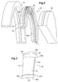
Figure 2 is a three-dimensional perspective view of a part of a steam turbine diaphragm according to an embodiment of the invention; -
Figure 3 is a three-dimensional perspective view of a static blade for use in the diaphragm construction ofFigure 2 ; -
Figure 4 is an upper view of the static blade ofFigure 3 ; and -
Figure 5 is a radial cross-section of a static blade ofFigure 3 , welded onto spacer bands of the steam turbine diaphragm ofFigure 2 . - The following detailed description of the exemplary embodiments refers to the accompanying drawings. The same reference numbers in different drawings identify the same or similar elements. Additionally, the drawings are not necessarily drawn to scale.
- As illustrated on
Figure 2 , a part of asteam turbine diaphragm 30 of a turbine comprises a nozzle unit having a plurality of identicalstatic blade aerofoils 32 fixed radially to aninner ring 34 and to anouter ring 36 by means of inner and outerannular spacer bands - The inner and
outer rings outer spacer bands - The inner and the
outer spacer bands holes holes spacer bands aerofoils 32 are then inserted in said though-holes and fillet welded into place. Theinner spacer band 38 is in turn welded to theinner ring 34 and theouter band 40 is in turn welded to theouter ring 36. - As illustrated on
Figures 3 and4 , eachstatic blade 32 has anaerofoil portion 44 having an elongated body having aninner end 32a brought into contact with theinner spacer band 38 and anouter end 32b, opposite to saidinner end 32a, brought into contact with theouter spacer band 40. - The inner and
outer ends outer spacer bands - Each
static blade 32 has, for example, a section substantially in the shape of a vane, as shown onFigure 4 , having a rounded and enlarged shape corresponding to the leadingedge 44a and a thinner part corresponding to thetrailing edge 44b. - As illustrated on
Figure 3 and4 , the inner andouter ends static blade 32 are provided respectively with an inner andouter reinforcement portion reinforcement portion aerofoil portion 44, as shown onFigure 4 , having a rounded and enlarged shape corresponding to the leadingedge trailing edge 46b, 48b. - Each
reinforcement portion aerofoil portion 44. The shape of thereinforcement portions aerofoil portion 44 in its whole, i.e at and near the leading andtrailing edges aerofoil portion 44. - The first and
second reinforcement portions holes spacer bands Figure 5 . Once all thestatic blades 32 have been assembled into thespacer bands welds welds Figure 4 . - The
static blades 32 are made of an alloy steel material, having for example, 12% of chrome. - Thanks to the reinforcement portions provided at each end of the aerofoil portions, the static blade is strengthen.
- Thanks to the invention, the diaphragm construction has good mechanical strength, while being economical and easy to manufacture.
Claims (8)
- Static blade (32) for an axial flow turbine comprising:an aerofoil portion (44) having a leading edge (44a), a trailing edge (44b), a pressure side and a suction side,radially inner and outer reinforcement portions (46, 48) integral with said aerofoil portion (44),wherein each reinforcement portion (46, 48) closely follows the shape of the section of the aerofoil portion (44).
- Static blade according to claim 1, wherein each reinforcement portion (46, 48) has a section substantially bigger than the section of the aerofoil portion (44), having a rounded and enlarged shape corresponding to the leading edge (46a, 48a) surrounding the leading edge (44a) of the aerofoil portion (44) and a thinner part corresponding to the trailing edge (46b, 48b) surrounding the trailing edge (44b) of the aerofoil portion (44).
- Static blade according to claim 1 or 2, made of an alloy steel material.
- Static blade according to claim 3, wherein the alloy steel material comprises 12% of chrome.
- An axial flow turbine diaphragm construction comprising:an annulus of a plurality of identical static blades according to any of the preceding claims,an inner and outer spacer bands (38, 40) having through-holes (38a, 40a) therein shaped to receive the inner and outer reinforcement portions (46, 48) of each static blade (32), anda radially inner and outer diaphragm rings (34, 36) surrounding the annular spacer bands (38, 40).
- Axial flow turbine diaphragm construction according to claim 5, wherein each reinforcement portions are welded to the corresponding spacer band (38, 40) by welds (50a, 50b; 52a, 52b).
- Axial flow turbine diaphragm construction according to claims 2 and 6, wherein of the welds 50a, 50b; 52a, 52b) are located at each leading and trailing edges (48a, 48b; 46a, 46b) of each reinforcement portions (46, 48).
- Axial flow turbine diaphragm construction according to any of claims 5 to 7, wherein the inner spacer band (38) is welded to the inner ring (34) and the outer band (40) is welded to the outer ring (36).
Priority Applications (5)
| Application Number | Priority Date | Filing Date | Title |
|---|---|---|---|
| EP16290110.2A EP3260663B1 (en) | 2016-06-21 | 2016-06-21 | Axial flow turbine diaphragm construction |
| CN201780038742.5A CN109312626B (en) | 2016-06-21 | 2017-06-21 | Stationary blade for a turbine diaphragm and associated turbine diaphragm |
| JP2018566573A JP6972035B2 (en) | 2016-06-21 | 2017-06-21 | Static blades for turbine diaphragms and related turbine diaphragms |
| US16/312,618 US20200182076A1 (en) | 2016-06-21 | 2017-06-21 | Static blade for a turbine diaphragm and associated turbine diaphragm |
| PCT/EP2017/065220 WO2017220646A1 (en) | 2016-06-21 | 2017-06-21 | Static blade for a turbine diaphragm and associated turbine diaphragm |
Applications Claiming Priority (1)
| Application Number | Priority Date | Filing Date | Title |
|---|---|---|---|
| EP16290110.2A EP3260663B1 (en) | 2016-06-21 | 2016-06-21 | Axial flow turbine diaphragm construction |
Publications (2)
| Publication Number | Publication Date |
|---|---|
| EP3260663A1 true EP3260663A1 (en) | 2017-12-27 |
| EP3260663B1 EP3260663B1 (en) | 2020-07-29 |
Family
ID=56787385
Family Applications (1)
| Application Number | Title | Priority Date | Filing Date |
|---|---|---|---|
| EP16290110.2A Active EP3260663B1 (en) | 2016-06-21 | 2016-06-21 | Axial flow turbine diaphragm construction |
Country Status (5)
| Country | Link |
|---|---|
| US (1) | US20200182076A1 (en) |
| EP (1) | EP3260663B1 (en) |
| JP (1) | JP6972035B2 (en) |
| CN (1) | CN109312626B (en) |
| WO (1) | WO2017220646A1 (en) |
Cited By (1)
| Publication number | Priority date | Publication date | Assignee | Title |
|---|---|---|---|---|
| CN115182789A (en) * | 2021-04-07 | 2022-10-14 | 中国航发商用航空发动机有限责任公司 | Stator assembly, method of manufacturing, and impeller machine including the stator assembly |
Families Citing this family (2)
| Publication number | Priority date | Publication date | Assignee | Title |
|---|---|---|---|---|
| CN112377278B (en) * | 2020-10-30 | 2023-04-28 | 北京国能龙威发电技术有限公司 | Complete circle assembly method of steam turbine self-crowned matched partition plate |
| US11879360B2 (en) * | 2020-10-30 | 2024-01-23 | General Electric Company | Fabricated CMC nozzle assemblies for gas turbine engines |
Citations (4)
| Publication number | Priority date | Publication date | Assignee | Title |
|---|---|---|---|---|
| EP0018806A1 (en) * | 1979-05-04 | 1980-11-12 | Trw Inc. | An assembly including an airfoil extending between shroud sections and method of making the same |
| US5474419A (en) * | 1992-12-30 | 1995-12-12 | Reluzco; George | Flowpath assembly for a turbine diaphragm and methods of manufacture |
| US20070224043A1 (en) * | 2006-03-27 | 2007-09-27 | Alstom Technology Ltd | Turbine blade and diaphragm construction |
| EP1847689A2 (en) * | 2006-04-21 | 2007-10-24 | General Electric Company | Apparatus and method of diaphragm assembly |
Family Cites Families (14)
| Publication number | Priority date | Publication date | Assignee | Title |
|---|---|---|---|---|
| US2681788A (en) * | 1951-05-23 | 1954-06-22 | Solar Aircraft Co | Gas turbine vane structure |
| JPS5152339A (en) * | 1974-10-16 | 1976-05-08 | Hitachi Ltd | Ishukinzokuno denshipiimuyosetsuhoho |
| JPS56116861A (en) * | 1980-02-21 | 1981-09-12 | Mitsubishi Heavy Ind Ltd | Martensite-textured stainless steel |
| JPS5958103A (en) * | 1982-09-28 | 1984-04-03 | Toshiba Corp | Steam turbine nozzle |
| US4728258A (en) * | 1985-04-25 | 1988-03-01 | Trw Inc. | Turbine engine component and method of making the same |
| JPH05231102A (en) * | 1992-02-18 | 1993-09-07 | Mitsubishi Heavy Ind Ltd | Manufacture of turbine partition wall |
| US5765993A (en) * | 1996-09-27 | 1998-06-16 | Chromalloy Gas Turbine Corporation | Replacement vane assembly for fan exit guide |
| US6579061B1 (en) * | 2001-07-27 | 2003-06-17 | General Electric Company | Selective step turbine nozzle |
| JP2007321644A (en) * | 2006-05-31 | 2007-12-13 | Toshiba Corp | Turbine nozzle |
| WO2008094221A1 (en) * | 2006-09-26 | 2008-08-07 | Pas Technologies Inc. | Method of repairing a stationary airfoil array directing three-dimensional flow |
| CN201071738Y (en) * | 2007-08-20 | 2008-06-11 | 如皋透平叶片制造有限公司 | Stationary blade of industrial steam turbine |
| CN101280693A (en) * | 2008-05-23 | 2008-10-08 | 无锡润和叶片制造有限公司 | 1000MW steam turbine distorting yataghan blade as well as method for manufacturing the same |
| JP5296046B2 (en) * | 2010-12-28 | 2013-09-25 | 株式会社日立製作所 | Ni-based alloy and turbine moving / stator blade of gas turbine using the same |
| US8684698B2 (en) * | 2011-03-25 | 2014-04-01 | General Electric Company | Compressor airfoil with tip dihedral |
-
2016
- 2016-06-21 EP EP16290110.2A patent/EP3260663B1/en active Active
-
2017
- 2017-06-21 JP JP2018566573A patent/JP6972035B2/en active Active
- 2017-06-21 CN CN201780038742.5A patent/CN109312626B/en active Active
- 2017-06-21 US US16/312,618 patent/US20200182076A1/en not_active Abandoned
- 2017-06-21 WO PCT/EP2017/065220 patent/WO2017220646A1/en not_active Ceased
Patent Citations (4)
| Publication number | Priority date | Publication date | Assignee | Title |
|---|---|---|---|---|
| EP0018806A1 (en) * | 1979-05-04 | 1980-11-12 | Trw Inc. | An assembly including an airfoil extending between shroud sections and method of making the same |
| US5474419A (en) * | 1992-12-30 | 1995-12-12 | Reluzco; George | Flowpath assembly for a turbine diaphragm and methods of manufacture |
| US20070224043A1 (en) * | 2006-03-27 | 2007-09-27 | Alstom Technology Ltd | Turbine blade and diaphragm construction |
| EP1847689A2 (en) * | 2006-04-21 | 2007-10-24 | General Electric Company | Apparatus and method of diaphragm assembly |
Cited By (1)
| Publication number | Priority date | Publication date | Assignee | Title |
|---|---|---|---|---|
| CN115182789A (en) * | 2021-04-07 | 2022-10-14 | 中国航发商用航空发动机有限责任公司 | Stator assembly, method of manufacturing, and impeller machine including the stator assembly |
Also Published As
| Publication number | Publication date |
|---|---|
| CN109312626A (en) | 2019-02-05 |
| US20200182076A1 (en) | 2020-06-11 |
| WO2017220646A1 (en) | 2017-12-28 |
| EP3260663B1 (en) | 2020-07-29 |
| JP2019518903A (en) | 2019-07-04 |
| CN109312626B (en) | 2022-06-24 |
| JP6972035B2 (en) | 2021-11-24 |
Similar Documents
| Publication | Publication Date | Title |
|---|---|---|
| EP2620591B1 (en) | Gas turbine engine stator vane assembly with inner shroud | |
| EP2896791B1 (en) | Mistuned airfoil assemblies | |
| EP1852575B1 (en) | Stationary blade ring of axial compressor | |
| EP3350452B1 (en) | High stiffness turbomachine impeller, turbomachine including said impeller and method of manufacturing | |
| JP5946543B2 (en) | Gas turbine engine support structure | |
| EP2204539A3 (en) | Stator assembly for a gas turbine engine | |
| WO2009157817A1 (en) | Vane assembly and method of fabricating, and a turbo-machine with such vane assembly | |
| EP3123002B1 (en) | Stator vane support system within a gas turbine engine | |
| EP1847689A2 (en) | Apparatus and method of diaphragm assembly | |
| EP3260663B1 (en) | Axial flow turbine diaphragm construction | |
| CN104011333A (en) | Turbomachine compressor guide vanes assembly | |
| US20150010395A1 (en) | Stator Blade Sector for an Axial Turbomachine with a Dual Means of Fixing | |
| MX2014012063A (en) | Stator blade diaphragm ring, turbo-machine and method. | |
| CN208380978U (en) | A kind of low-pressure compressor casing assembling unit structure | |
| EP3336318B1 (en) | Struts for exhaust frames of turbine systems | |
| US20130034445A1 (en) | Turbine bucket having axially extending groove | |
| US20200024998A1 (en) | Turbine engine vane arrangement having a plurality of interconnected vane arrangement segments | |
| US20070071605A1 (en) | Integrated nozzle and bucket wheels for reaction steam turbine stationary components and related method | |
| EP1582698A1 (en) | Integral covered nozzle with attached overcover | |
| US8333553B2 (en) | Compressor of a gas turbine | |
| US20040120813A1 (en) | Methods and apparatus for securing turbine nozzles | |
| EP1764482A2 (en) | Single piece nozzle wheel and manufacturing method | |
| US20190153882A1 (en) | Turbine Guide Apparatus | |
| GB996773A (en) | Improvements in interstage diaphragms for turbines and axial-flow compressors | |
| EP3441648A1 (en) | Seal segment and rotary machine |
Legal Events
| Date | Code | Title | Description |
|---|---|---|---|
| PUAI | Public reference made under article 153(3) epc to a published international application that has entered the european phase |
Free format text: ORIGINAL CODE: 0009012 |
|
| STAA | Information on the status of an ep patent application or granted ep patent |
Free format text: STATUS: THE APPLICATION HAS BEEN PUBLISHED |
|
| AK | Designated contracting states |
Kind code of ref document: A1 Designated state(s): AL AT BE BG CH CY CZ DE DK EE ES FI FR GB GR HR HU IE IS IT LI LT LU LV MC MK MT NL NO PL PT RO RS SE SI SK SM TR |
|
| AX | Request for extension of the european patent |
Extension state: BA ME |
|
| STAA | Information on the status of an ep patent application or granted ep patent |
Free format text: STATUS: REQUEST FOR EXAMINATION WAS MADE |
|
| 17P | Request for examination filed |
Effective date: 20180627 |
|
| RBV | Designated contracting states (corrected) |
Designated state(s): AL AT BE BG CH CY CZ DE DK EE ES FI FR GB GR HR HU IE IS IT LI LT LU LV MC MK MT NL NO PL PT RO RS SE SI SK SM TR |
|
| STAA | Information on the status of an ep patent application or granted ep patent |
Free format text: STATUS: EXAMINATION IS IN PROGRESS |
|
| 17Q | First examination report despatched |
Effective date: 20180905 |
|
| GRAP | Despatch of communication of intention to grant a patent |
Free format text: ORIGINAL CODE: EPIDOSNIGR1 |
|
| STAA | Information on the status of an ep patent application or granted ep patent |
Free format text: STATUS: GRANT OF PATENT IS INTENDED |
|
| INTG | Intention to grant announced |
Effective date: 20200218 |
|
| GRAS | Grant fee paid |
Free format text: ORIGINAL CODE: EPIDOSNIGR3 |
|
| GRAA | (expected) grant |
Free format text: ORIGINAL CODE: 0009210 |
|
| STAA | Information on the status of an ep patent application or granted ep patent |
Free format text: STATUS: THE PATENT HAS BEEN GRANTED |
|
| AK | Designated contracting states |
Kind code of ref document: B1 Designated state(s): AL AT BE BG CH CY CZ DE DK EE ES FI FR GB GR HR HU IE IS IT LI LT LU LV MC MK MT NL NO PL PT RO RS SE SI SK SM TR |
|
| REG | Reference to a national code |
Ref country code: CH Ref legal event code: EP |
|
| REG | Reference to a national code |
Ref country code: AT Ref legal event code: REF Ref document number: 1296035 Country of ref document: AT Kind code of ref document: T Effective date: 20200815 |
|
| REG | Reference to a national code |
Ref country code: IE Ref legal event code: FG4D |
|
| REG | Reference to a national code |
Ref country code: DE Ref legal event code: R096 Ref document number: 602016040747 Country of ref document: DE |
|
| REG | Reference to a national code |
Ref country code: LT Ref legal event code: MG4D |
|
| REG | Reference to a national code |
Ref country code: NL Ref legal event code: MP Effective date: 20200729 |
|
| REG | Reference to a national code |
Ref country code: AT Ref legal event code: MK05 Ref document number: 1296035 Country of ref document: AT Kind code of ref document: T Effective date: 20200729 |
|
| PG25 | Lapsed in a contracting state [announced via postgrant information from national office to epo] |
Ref country code: NO Free format text: LAPSE BECAUSE OF FAILURE TO SUBMIT A TRANSLATION OF THE DESCRIPTION OR TO PAY THE FEE WITHIN THE PRESCRIBED TIME-LIMIT Effective date: 20201029 Ref country code: ES Free format text: LAPSE BECAUSE OF FAILURE TO SUBMIT A TRANSLATION OF THE DESCRIPTION OR TO PAY THE FEE WITHIN THE PRESCRIBED TIME-LIMIT Effective date: 20200729 Ref country code: AT Free format text: LAPSE BECAUSE OF FAILURE TO SUBMIT A TRANSLATION OF THE DESCRIPTION OR TO PAY THE FEE WITHIN THE PRESCRIBED TIME-LIMIT Effective date: 20200729 Ref country code: BG Free format text: LAPSE BECAUSE OF FAILURE TO SUBMIT A TRANSLATION OF THE DESCRIPTION OR TO PAY THE FEE WITHIN THE PRESCRIBED TIME-LIMIT Effective date: 20201029 Ref country code: FI Free format text: LAPSE BECAUSE OF FAILURE TO SUBMIT A TRANSLATION OF THE DESCRIPTION OR TO PAY THE FEE WITHIN THE PRESCRIBED TIME-LIMIT Effective date: 20200729 Ref country code: GR Free format text: LAPSE BECAUSE OF FAILURE TO SUBMIT A TRANSLATION OF THE DESCRIPTION OR TO PAY THE FEE WITHIN THE PRESCRIBED TIME-LIMIT Effective date: 20201030 Ref country code: LT Free format text: LAPSE BECAUSE OF FAILURE TO SUBMIT A TRANSLATION OF THE DESCRIPTION OR TO PAY THE FEE WITHIN THE PRESCRIBED TIME-LIMIT Effective date: 20200729 Ref country code: PT Free format text: LAPSE BECAUSE OF FAILURE TO SUBMIT A TRANSLATION OF THE DESCRIPTION OR TO PAY THE FEE WITHIN THE PRESCRIBED TIME-LIMIT Effective date: 20201130 Ref country code: HR Free format text: LAPSE BECAUSE OF FAILURE TO SUBMIT A TRANSLATION OF THE DESCRIPTION OR TO PAY THE FEE WITHIN THE PRESCRIBED TIME-LIMIT Effective date: 20200729 Ref country code: SE Free format text: LAPSE BECAUSE OF FAILURE TO SUBMIT A TRANSLATION OF THE DESCRIPTION OR TO PAY THE FEE WITHIN THE PRESCRIBED TIME-LIMIT Effective date: 20200729 |
|
| PG25 | Lapsed in a contracting state [announced via postgrant information from national office to epo] |
Ref country code: LV Free format text: LAPSE BECAUSE OF FAILURE TO SUBMIT A TRANSLATION OF THE DESCRIPTION OR TO PAY THE FEE WITHIN THE PRESCRIBED TIME-LIMIT Effective date: 20200729 Ref country code: PL Free format text: LAPSE BECAUSE OF FAILURE TO SUBMIT A TRANSLATION OF THE DESCRIPTION OR TO PAY THE FEE WITHIN THE PRESCRIBED TIME-LIMIT Effective date: 20200729 Ref country code: RS Free format text: LAPSE BECAUSE OF FAILURE TO SUBMIT A TRANSLATION OF THE DESCRIPTION OR TO PAY THE FEE WITHIN THE PRESCRIBED TIME-LIMIT Effective date: 20200729 Ref country code: IS Free format text: LAPSE BECAUSE OF FAILURE TO SUBMIT A TRANSLATION OF THE DESCRIPTION OR TO PAY THE FEE WITHIN THE PRESCRIBED TIME-LIMIT Effective date: 20201129 |
|
| PG25 | Lapsed in a contracting state [announced via postgrant information from national office to epo] |
Ref country code: NL Free format text: LAPSE BECAUSE OF FAILURE TO SUBMIT A TRANSLATION OF THE DESCRIPTION OR TO PAY THE FEE WITHIN THE PRESCRIBED TIME-LIMIT Effective date: 20200729 |
|
| PG25 | Lapsed in a contracting state [announced via postgrant information from national office to epo] |
Ref country code: CZ Free format text: LAPSE BECAUSE OF FAILURE TO SUBMIT A TRANSLATION OF THE DESCRIPTION OR TO PAY THE FEE WITHIN THE PRESCRIBED TIME-LIMIT Effective date: 20200729 Ref country code: DK Free format text: LAPSE BECAUSE OF FAILURE TO SUBMIT A TRANSLATION OF THE DESCRIPTION OR TO PAY THE FEE WITHIN THE PRESCRIBED TIME-LIMIT Effective date: 20200729 Ref country code: SM Free format text: LAPSE BECAUSE OF FAILURE TO SUBMIT A TRANSLATION OF THE DESCRIPTION OR TO PAY THE FEE WITHIN THE PRESCRIBED TIME-LIMIT Effective date: 20200729 Ref country code: RO Free format text: LAPSE BECAUSE OF FAILURE TO SUBMIT A TRANSLATION OF THE DESCRIPTION OR TO PAY THE FEE WITHIN THE PRESCRIBED TIME-LIMIT Effective date: 20200729 Ref country code: IT Free format text: LAPSE BECAUSE OF FAILURE TO SUBMIT A TRANSLATION OF THE DESCRIPTION OR TO PAY THE FEE WITHIN THE PRESCRIBED TIME-LIMIT Effective date: 20200729 Ref country code: EE Free format text: LAPSE BECAUSE OF FAILURE TO SUBMIT A TRANSLATION OF THE DESCRIPTION OR TO PAY THE FEE WITHIN THE PRESCRIBED TIME-LIMIT Effective date: 20200729 |
|
| REG | Reference to a national code |
Ref country code: DE Ref legal event code: R097 Ref document number: 602016040747 Country of ref document: DE |
|
| RAP4 | Party data changed (patent owner data changed or rights of a patent transferred) |
Owner name: GENERAL ELECTRIC TECHNOLOGY GMBH |
|
| PG25 | Lapsed in a contracting state [announced via postgrant information from national office to epo] |
Ref country code: AL Free format text: LAPSE BECAUSE OF FAILURE TO SUBMIT A TRANSLATION OF THE DESCRIPTION OR TO PAY THE FEE WITHIN THE PRESCRIBED TIME-LIMIT Effective date: 20200729 |
|
| PLBE | No opposition filed within time limit |
Free format text: ORIGINAL CODE: 0009261 |
|
| STAA | Information on the status of an ep patent application or granted ep patent |
Free format text: STATUS: NO OPPOSITION FILED WITHIN TIME LIMIT |
|
| PG25 | Lapsed in a contracting state [announced via postgrant information from national office to epo] |
Ref country code: SK Free format text: LAPSE BECAUSE OF FAILURE TO SUBMIT A TRANSLATION OF THE DESCRIPTION OR TO PAY THE FEE WITHIN THE PRESCRIBED TIME-LIMIT Effective date: 20200729 |
|
| 26N | No opposition filed |
Effective date: 20210430 |
|
| PG25 | Lapsed in a contracting state [announced via postgrant information from national office to epo] |
Ref country code: SI Free format text: LAPSE BECAUSE OF FAILURE TO SUBMIT A TRANSLATION OF THE DESCRIPTION OR TO PAY THE FEE WITHIN THE PRESCRIBED TIME-LIMIT Effective date: 20200729 |
|
| PG25 | Lapsed in a contracting state [announced via postgrant information from national office to epo] |
Ref country code: MC Free format text: LAPSE BECAUSE OF FAILURE TO SUBMIT A TRANSLATION OF THE DESCRIPTION OR TO PAY THE FEE WITHIN THE PRESCRIBED TIME-LIMIT Effective date: 20200729 |
|
| REG | Reference to a national code |
Ref country code: CH Ref legal event code: PL |
|
| GBPC | Gb: european patent ceased through non-payment of renewal fee |
Effective date: 20210621 |
|
| REG | Reference to a national code |
Ref country code: BE Ref legal event code: MM Effective date: 20210630 |
|
| PG25 | Lapsed in a contracting state [announced via postgrant information from national office to epo] |
Ref country code: LU Free format text: LAPSE BECAUSE OF NON-PAYMENT OF DUE FEES Effective date: 20210621 |
|
| PG25 | Lapsed in a contracting state [announced via postgrant information from national office to epo] |
Ref country code: LI Free format text: LAPSE BECAUSE OF NON-PAYMENT OF DUE FEES Effective date: 20210630 Ref country code: IE Free format text: LAPSE BECAUSE OF NON-PAYMENT OF DUE FEES Effective date: 20210621 Ref country code: GB Free format text: LAPSE BECAUSE OF NON-PAYMENT OF DUE FEES Effective date: 20210621 Ref country code: CH Free format text: LAPSE BECAUSE OF NON-PAYMENT OF DUE FEES Effective date: 20210630 |
|
| PG25 | Lapsed in a contracting state [announced via postgrant information from national office to epo] |
Ref country code: FR Free format text: LAPSE BECAUSE OF NON-PAYMENT OF DUE FEES Effective date: 20210630 |
|
| PG25 | Lapsed in a contracting state [announced via postgrant information from national office to epo] |
Ref country code: BE Free format text: LAPSE BECAUSE OF NON-PAYMENT OF DUE FEES Effective date: 20210630 |
|
| PG25 | Lapsed in a contracting state [announced via postgrant information from national office to epo] |
Ref country code: HU Free format text: LAPSE BECAUSE OF FAILURE TO SUBMIT A TRANSLATION OF THE DESCRIPTION OR TO PAY THE FEE WITHIN THE PRESCRIBED TIME-LIMIT; INVALID AB INITIO Effective date: 20160621 |
|
| P01 | Opt-out of the competence of the unified patent court (upc) registered |
Effective date: 20230523 |
|
| PG25 | Lapsed in a contracting state [announced via postgrant information from national office to epo] |
Ref country code: CY Free format text: LAPSE BECAUSE OF FAILURE TO SUBMIT A TRANSLATION OF THE DESCRIPTION OR TO PAY THE FEE WITHIN THE PRESCRIBED TIME-LIMIT Effective date: 20200729 |
|
| PG25 | Lapsed in a contracting state [announced via postgrant information from national office to epo] |
Ref country code: MK Free format text: LAPSE BECAUSE OF FAILURE TO SUBMIT A TRANSLATION OF THE DESCRIPTION OR TO PAY THE FEE WITHIN THE PRESCRIBED TIME-LIMIT Effective date: 20200729 |
|
| PG25 | Lapsed in a contracting state [announced via postgrant information from national office to epo] |
Ref country code: MT Free format text: LAPSE BECAUSE OF FAILURE TO SUBMIT A TRANSLATION OF THE DESCRIPTION OR TO PAY THE FEE WITHIN THE PRESCRIBED TIME-LIMIT Effective date: 20200729 |
|
| REG | Reference to a national code |
Ref country code: DE Ref legal event code: R081 Ref document number: 602016040747 Country of ref document: DE Owner name: ARABELLE SOLUTIONS FRANCE, FR Free format text: FORMER OWNER: GENERAL ELECTRIC TECHNOLOGY GMBH, BADEN, CH Ref country code: DE Ref legal event code: R081 Ref document number: 602016040747 Country of ref document: DE Owner name: ARABELLE TECHNOLOGIES, FR Free format text: FORMER OWNER: GENERAL ELECTRIC TECHNOLOGY GMBH, BADEN, CH |
|
| REG | Reference to a national code |
Ref country code: DE Ref legal event code: R081 Ref document number: 602016040747 Country of ref document: DE Owner name: ARABELLE SOLUTIONS FRANCE, FR Free format text: FORMER OWNER: ARABELLE TECHNOLOGIES, BOULOGNE-BILLANCOURT, FR |
|
| PGFP | Annual fee paid to national office [announced via postgrant information from national office to epo] |
Ref country code: DE Payment date: 20250520 Year of fee payment: 10 |
|
| PG25 | Lapsed in a contracting state [announced via postgrant information from national office to epo] |
Ref country code: TR Free format text: LAPSE BECAUSE OF FAILURE TO SUBMIT A TRANSLATION OF THE DESCRIPTION OR TO PAY THE FEE WITHIN THE PRESCRIBED TIME-LIMIT Effective date: 20200729 |