EP3260659B1 - Bläserschaufelfüllstoff - Google Patents
Bläserschaufelfüllstoff Download PDFInfo
- Publication number
- EP3260659B1 EP3260659B1 EP17177470.6A EP17177470A EP3260659B1 EP 3260659 B1 EP3260659 B1 EP 3260659B1 EP 17177470 A EP17177470 A EP 17177470A EP 3260659 B1 EP3260659 B1 EP 3260659B1
- Authority
- EP
- European Patent Office
- Prior art keywords
- blade
- filler
- fan
- bumps
- fan blade
- Prior art date
- Legal status (The legal status is an assumption and is not a legal conclusion. Google has not performed a legal analysis and makes no representation as to the accuracy of the status listed.)
- Active
Links
- 239000000945 filler Substances 0.000 title claims description 117
- 239000000853 adhesive Substances 0.000 claims description 28
- 230000001070 adhesive effect Effects 0.000 claims description 28
- 239000000463 material Substances 0.000 claims description 24
- 238000000034 method Methods 0.000 claims description 16
- 229920005830 Polyurethane Foam Polymers 0.000 claims description 4
- 239000011496 polyurethane foam Substances 0.000 claims description 4
- 238000000748 compression moulding Methods 0.000 claims description 2
- 238000001746 injection moulding Methods 0.000 claims description 2
- 239000007789 gas Substances 0.000 description 23
- 230000008901 benefit Effects 0.000 description 6
- 238000004519 manufacturing process Methods 0.000 description 6
- 239000006260 foam Substances 0.000 description 5
- 238000003754 machining Methods 0.000 description 4
- XAGFODPZIPBFFR-UHFFFAOYSA-N aluminium Chemical compound [Al] XAGFODPZIPBFFR-UHFFFAOYSA-N 0.000 description 3
- 229910052782 aluminium Inorganic materials 0.000 description 3
- 239000000567 combustion gas Substances 0.000 description 3
- 230000006835 compression Effects 0.000 description 3
- 238000007906 compression Methods 0.000 description 3
- 230000008569 process Effects 0.000 description 3
- 229910000838 Al alloy Inorganic materials 0.000 description 2
- 239000004593 Epoxy Substances 0.000 description 2
- 229910001069 Ti alloy Inorganic materials 0.000 description 2
- RTAQQCXQSZGOHL-UHFFFAOYSA-N Titanium Chemical compound [Ti] RTAQQCXQSZGOHL-UHFFFAOYSA-N 0.000 description 2
- 230000000712 assembly Effects 0.000 description 2
- 238000000429 assembly Methods 0.000 description 2
- 239000002131 composite material Substances 0.000 description 2
- 239000002826 coolant Substances 0.000 description 2
- 239000004744 fabric Substances 0.000 description 2
- 239000000446 fuel Substances 0.000 description 2
- 238000002347 injection Methods 0.000 description 2
- 239000007924 injection Substances 0.000 description 2
- 238000003801 milling Methods 0.000 description 2
- 229920002635 polyurethane Polymers 0.000 description 2
- 239000004814 polyurethane Substances 0.000 description 2
- 230000003068 static effect Effects 0.000 description 2
- 229910052719 titanium Inorganic materials 0.000 description 2
- 239000010936 titanium Substances 0.000 description 2
- JOYRKODLDBILNP-UHFFFAOYSA-N Ethyl urethane Chemical compound CCOC(N)=O JOYRKODLDBILNP-UHFFFAOYSA-N 0.000 description 1
- 239000004698 Polyethylene Substances 0.000 description 1
- 239000000654 additive Substances 0.000 description 1
- 230000000996 additive effect Effects 0.000 description 1
- 238000005266 casting Methods 0.000 description 1
- 238000004891 communication Methods 0.000 description 1
- 230000000295 complement effect Effects 0.000 description 1
- 230000008878 coupling Effects 0.000 description 1
- 238000010168 coupling process Methods 0.000 description 1
- 238000005859 coupling reaction Methods 0.000 description 1
- 238000013036 cure process Methods 0.000 description 1
- 229920001971 elastomer Polymers 0.000 description 1
- 238000009760 electrical discharge machining Methods 0.000 description 1
- 239000000284 extract Substances 0.000 description 1
- 238000005242 forging Methods 0.000 description 1
- 238000000227 grinding Methods 0.000 description 1
- 230000012447 hatching Effects 0.000 description 1
- 239000003562 lightweight material Substances 0.000 description 1
- 239000006262 metallic foam Substances 0.000 description 1
- 238000000465 moulding Methods 0.000 description 1
- -1 polyethylene Polymers 0.000 description 1
- 229920000573 polyethylene Polymers 0.000 description 1
- 229920000642 polymer Polymers 0.000 description 1
- 230000009467 reduction Effects 0.000 description 1
- 230000004044 response Effects 0.000 description 1
- 239000000126 substance Substances 0.000 description 1
- 239000013585 weight reducing agent Substances 0.000 description 1
Images


Classifications
-
- F—MECHANICAL ENGINEERING; LIGHTING; HEATING; WEAPONS; BLASTING
- F04—POSITIVE - DISPLACEMENT MACHINES FOR LIQUIDS; PUMPS FOR LIQUIDS OR ELASTIC FLUIDS
- F04D—NON-POSITIVE-DISPLACEMENT PUMPS
- F04D29/00—Details, component parts, or accessories
- F04D29/26—Rotors specially for elastic fluids
- F04D29/32—Rotors specially for elastic fluids for axial flow pumps
- F04D29/38—Blades
- F04D29/388—Blades characterised by construction
-
- B—PERFORMING OPERATIONS; TRANSPORTING
- B29—WORKING OF PLASTICS; WORKING OF SUBSTANCES IN A PLASTIC STATE IN GENERAL
- B29C—SHAPING OR JOINING OF PLASTICS; SHAPING OF MATERIAL IN A PLASTIC STATE, NOT OTHERWISE PROVIDED FOR; AFTER-TREATMENT OF THE SHAPED PRODUCTS, e.g. REPAIRING
- B29C65/00—Joining or sealing of preformed parts, e.g. welding of plastics materials; Apparatus therefor
- B29C65/78—Means for handling the parts to be joined, e.g. for making containers or hollow articles, e.g. means for handling sheets, plates, web-like materials, tubular articles, hollow articles or elements to be joined therewith; Means for discharging the joined articles from the joining apparatus
- B29C65/7802—Positioning the parts to be joined, e.g. aligning, indexing or centring
- B29C65/782—Positioning the parts to be joined, e.g. aligning, indexing or centring by setting the gap between the parts to be joined
- B29C65/7823—Positioning the parts to be joined, e.g. aligning, indexing or centring by setting the gap between the parts to be joined by using distance pieces, i.e. by using spacers positioned between the parts to be joined and forming a part of the joint
- B29C65/7829—Positioning the parts to be joined, e.g. aligning, indexing or centring by setting the gap between the parts to be joined by using distance pieces, i.e. by using spacers positioned between the parts to be joined and forming a part of the joint said distance pieces being integral with at least one of the parts to be joined
-
- F—MECHANICAL ENGINEERING; LIGHTING; HEATING; WEAPONS; BLASTING
- F01—MACHINES OR ENGINES IN GENERAL; ENGINE PLANTS IN GENERAL; STEAM ENGINES
- F01D—NON-POSITIVE DISPLACEMENT MACHINES OR ENGINES, e.g. STEAM TURBINES
- F01D5/00—Blades; Blade-carrying members; Heating, heat-insulating, cooling or antivibration means on the blades or the members
- F01D5/12—Blades
- F01D5/14—Form or construction
- F01D5/147—Construction, i.e. structural features, e.g. of weight-saving hollow blades
-
- F—MECHANICAL ENGINEERING; LIGHTING; HEATING; WEAPONS; BLASTING
- F01—MACHINES OR ENGINES IN GENERAL; ENGINE PLANTS IN GENERAL; STEAM ENGINES
- F01D—NON-POSITIVE DISPLACEMENT MACHINES OR ENGINES, e.g. STEAM TURBINES
- F01D5/00—Blades; Blade-carrying members; Heating, heat-insulating, cooling or antivibration means on the blades or the members
- F01D5/12—Blades
- F01D5/14—Form or construction
- F01D5/18—Hollow blades, i.e. blades with cooling or heating channels or cavities; Heating, heat-insulating or cooling means on blades
-
- F—MECHANICAL ENGINEERING; LIGHTING; HEATING; WEAPONS; BLASTING
- F04—POSITIVE - DISPLACEMENT MACHINES FOR LIQUIDS; PUMPS FOR LIQUIDS OR ELASTIC FLUIDS
- F04D—NON-POSITIVE-DISPLACEMENT PUMPS
- F04D19/00—Axial-flow pumps
- F04D19/002—Axial flow fans
-
- F—MECHANICAL ENGINEERING; LIGHTING; HEATING; WEAPONS; BLASTING
- F05—INDEXING SCHEMES RELATING TO ENGINES OR PUMPS IN VARIOUS SUBCLASSES OF CLASSES F01-F04
- F05D—INDEXING SCHEME FOR ASPECTS RELATING TO NON-POSITIVE-DISPLACEMENT MACHINES OR ENGINES, GAS-TURBINES OR JET-PROPULSION PLANTS
- F05D2220/00—Application
- F05D2220/30—Application in turbines
- F05D2220/32—Application in turbines in gas turbines
-
- F—MECHANICAL ENGINEERING; LIGHTING; HEATING; WEAPONS; BLASTING
- F05—INDEXING SCHEMES RELATING TO ENGINES OR PUMPS IN VARIOUS SUBCLASSES OF CLASSES F01-F04
- F05D—INDEXING SCHEME FOR ASPECTS RELATING TO NON-POSITIVE-DISPLACEMENT MACHINES OR ENGINES, GAS-TURBINES OR JET-PROPULSION PLANTS
- F05D2240/00—Components
- F05D2240/20—Rotors
- F05D2240/30—Characteristics of rotor blades, i.e. of any element transforming dynamic fluid energy to or from rotational energy and being attached to a rotor
- F05D2240/301—Cross-sectional characteristics
-
- F—MECHANICAL ENGINEERING; LIGHTING; HEATING; WEAPONS; BLASTING
- F05—INDEXING SCHEMES RELATING TO ENGINES OR PUMPS IN VARIOUS SUBCLASSES OF CLASSES F01-F04
- F05D—INDEXING SCHEME FOR ASPECTS RELATING TO NON-POSITIVE-DISPLACEMENT MACHINES OR ENGINES, GAS-TURBINES OR JET-PROPULSION PLANTS
- F05D2300/00—Materials; Properties thereof
- F05D2300/40—Organic materials
- F05D2300/43—Synthetic polymers, e.g. plastics; Rubber
-
- F—MECHANICAL ENGINEERING; LIGHTING; HEATING; WEAPONS; BLASTING
- F05—INDEXING SCHEMES RELATING TO ENGINES OR PUMPS IN VARIOUS SUBCLASSES OF CLASSES F01-F04
- F05D—INDEXING SCHEME FOR ASPECTS RELATING TO NON-POSITIVE-DISPLACEMENT MACHINES OR ENGINES, GAS-TURBINES OR JET-PROPULSION PLANTS
- F05D2300/00—Materials; Properties thereof
- F05D2300/60—Properties or characteristics given to material by treatment or manufacturing
- F05D2300/612—Foam
-
- Y—GENERAL TAGGING OF NEW TECHNOLOGICAL DEVELOPMENTS; GENERAL TAGGING OF CROSS-SECTIONAL TECHNOLOGIES SPANNING OVER SEVERAL SECTIONS OF THE IPC; TECHNICAL SUBJECTS COVERED BY FORMER USPC CROSS-REFERENCE ART COLLECTIONS [XRACs] AND DIGESTS
- Y02—TECHNOLOGIES OR APPLICATIONS FOR MITIGATION OR ADAPTATION AGAINST CLIMATE CHANGE
- Y02T—CLIMATE CHANGE MITIGATION TECHNOLOGIES RELATED TO TRANSPORTATION
- Y02T50/00—Aeronautics or air transport
- Y02T50/60—Efficient propulsion technologies, e.g. for aircraft
Definitions
- the present disclosure relates to gas turbine engines, and, more specifically, to a rotor or fan blade assembly.
- a gas turbine engine typically includes a fan section, a compressor section, a combustor section, and a turbine section.
- a fan section may drive air along a bypass flowpath while a compressor section may drive air along a core flowpath.
- air is pressurized in the compressor section and is mixed with fuel and burned in the combustor section to generate hot combustion gases.
- the hot combustion gases flow through the turbine section, which extracts energy from the hot combustion gases to power the compressor section and other gas turbine engine loads.
- the compressor section typically includes low pressure and high pressure compressors, and the turbine section includes low pressure and high pressure turbines.
- the fan section, compressor section, and turbine section typically include a series of rotor systems.
- Rotor systems typically include a disk and a plurality of circumferentially spaced blades, such as fan blades.
- a fan blade may be formed with hollow portions in the blade body to reduce weight of the blade.
- the hollow portions of a fan blade may contain filler materials. Filler material and fan blade surfaces may be relatively smooth, and bonding the filler material to the fan blade may be difficult.
- Porous mesh fabric, or scrim which is used for bonding the filler material to the fan blade, may be difficult to manufacture and apply to non-planar surfaces. Scrim fabrics may tend to fray and may increase manufacturing costs, particularly as the complexity of filler material and fan blade surfaces increases.
- EP2518270A2 discloses a prior art fan blade as set forth in the preamble of claim 1.
- EP2243929A2 discloses a prior art fan blade.
- a fan blade of a gas turbine engine is provided according to claim 1.
- an adhesive may be formed on the first surface of the blade filler.
- the first surface of the blade filler may be bonded to the inner surface of the blade body.
- the first surface of the blade filler may comprise a non-planar surface.
- the bump may have a height between 0.20 mm (0.008 inches) to 0.30 mm (0.012 inches).
- a blade cover may be disposed over the blade filler and the cavity. The first surface of the blade filler may be bonded to the blade cover.
- a material of the blade filler may comprise a closed cell polyurethane foam.
- a method for forming a fan blade is also provided according to claim 10.
- the method may further include the step of applying an adhesive to at least one of the fan blade component or the first surface of the blade filler.
- the fan blade component may include at least one of the blade body or a blade cover.
- the method may further include the step of forming the blade filler further comprises at least one of compression molding or injection molding the blade filler and the integral bump.
- any reference to attached, fixed, connected, or the like may include permanent, removable, temporary, partial, full, and/or any other possible attachment option. Additionally, any reference to without contact (or similar phrases) may also include reduced contact or minimal contact.
- Cross hatching lines may be used throughout the figures to denote different parts but not necessarily to denote the same or different materials.
- tail refers to the direction associated with the tail (e.g., the back end) of an aircraft, or generally, to the direction of exhaust of the gas turbine engine.
- forward refers to the direction associated with the nose (e.g., the front end) of an aircraft, or generally, to the direction of flight or motion.
- Gas turbine engine 20 may be a two-spool turbofan that generally incorporates a fan section 22, a compressor section 24, a combustor section 26 and a turbine section 28.
- Alternative engines may include, for example, an augmentor section among other systems or features.
- fan section 22 can drive coolant (e.g., air) along a bypass flow-path B while compressor section 24 can drive coolant along a core flow-path C for compression and communication into combustor section 26 then expansion through turbine section 28.
- coolant e.g., air
- compressor section 24 can drive coolant along a core flow-path C for compression and communication into combustor section 26 then expansion through turbine section 28.
- Gas turbine engine 20 may generally comprise a low speed spool 30 and a high speed spool 32 mounted for rotation about an engine central longitudinal axis A-A' relative to an engine static structure 36 or engine case via several bearing systems 38, 38-1, and 38-2.
- Engine central longitudinal axis A-A' is oriented in the z direction on the provided xyz axis. It should be understood that various bearing systems 38 at various locations may alternatively or additionally be provided, including for example, bearing system 38, bearing system 38-1, and bearing system 38-2.
- Low speed spool 30 may generally comprise an inner shaft 40 that interconnects a fan 42, a low pressure compressor 44 and a low pressure turbine 46.
- Inner shaft 40 may be connected to fan 42 through a geared architecture 48 that can drive fan 42 at a lower speed than low speed spool 30.
- Geared architecture 48 may comprise a gear assembly 60 enclosed within a gear housing 62.
- Gear assembly 60 couples inner shaft 40 to a rotating fan structure.
- High speed spool 32 may comprise an outer shaft 50 that interconnects a high pressure compressor 52 and high pressure turbine 54.
- a combustor 56 may be located between high pressure compressor 52 and high pressure turbine 54.
- a mid-turbine frame 57 of engine static structure 36 may be located generally between high pressure turbine 54 and low pressure turbine 46.
- Mid-turbine frame 57 may support one or more bearing systems 38 in turbine section 28.
- Inner shaft 40 and outer shaft 50 may be concentric and rotate via bearing systems 38 about the engine central longitudinal axis A-A', which is collinear with their longitudinal axes.
- A-A' the engine central longitudinal axis A-A'
- the core airflow C may be compressed by low pressure compressor 44 then high pressure compressor 52, mixed and burned with fuel in combustor 56, then expanded over high pressure turbine 54 and low pressure turbine 46.
- Turbines 46, 54 rotationally drive the respective low speed spool 30 and high speed spool 32 in response to the expansion.
- Gas turbine engine 20 may be, for example, a high-bypass ratio geared aircraft engine. In various embodiments, the bypass ratio of gas turbine engine 20 may be greater than about six. In various embodiments, the bypass ratio of gas turbine engine 20 may be greater than ten.
- geared architecture 48 may be an epicyclic gear train, such as a star gear system (sun gear in meshing engagement with a plurality of star gears supported by a carrier and in meshing engagement with a ring gear) or other gear system. Geared architecture 48 may have a gear reduction ratio of greater than about 2.3 and low pressure turbine 46 may have a pressure ratio that is greater than about five. In various embodiments, the bypass ratio of gas turbine engine 20 is greater than about ten.
- the diameter of fan 42 may be significantly larger than that of the low pressure compressor 44, and the low pressure turbine 46 may have a pressure ratio that is greater than about five.
- Low pressure turbine 46 pressure ratio may be measured prior to inlet of low pressure turbine 46 as related to the pressure at the outlet of low pressure turbine 46 prior to an exhaust nozzle.
- a gas turbine engine may comprise an industrial gas turbine (IGT) or a geared aircraft engine, such as a geared turbofan, or non-geared aircraft engine, such as a turbofan, or may comprise any gas turbine engine as desired.
- IGT industrial gas turbine
- a geared aircraft engine such as a geared turbofan
- non-geared aircraft engine such as a turbofan
- the fan section 22, the compressor section 24 and the turbine section 28 may each comprise rotor systems including blade assemblies having one or more sets of rotating blades, which may rotate about engine central longitudinal axis A-A'.
- hollow blades including filler material advantageously reduce the weight associated with the larger blades.
- Blade assembly 100 may comprise a plurality of rotating blades or fan blades 102 (or airfoil, rotor blade, etc.) extending radially outward from disk 104, which may be configured to rotate about engine central longitudinal axis A-A'.
- Disk 104 may be centered on the rotational axis of gas turbine engine 20 with a plurality of fan blades 102 attached to the disk 104 and spaced apart in the circumferential or tangential direction.
- Fan blade 102 may include a hub end or root 124 attached to the disk 104 and a radially outer edge or tip 126 located radially outward from the root 124.
- Fan blade 102 may include a leading edge 106 opposite to trailing edge 108.
- Fan blade 102 may further include a blade body 110 between a leading edge 106 and a trailing edge 108 of fan blade 102.
- the leading edge 106 and trailing edge 108 may extend from root 124 to tip 126 of fan blade 102, with root 124 being located radially inward with respect to blade body 110 and tip 126 being located radially outward with respect to blade body 110.
- Fan blade 102 may further include a generally concave pressure side and a generally convex suction side joined together at the respective leading edge 106 and trailing edge 108.
- Fan blade 102 may be curved and twisted relative to, for example, a plane extending radially from the disk 104, in terms of the fan blade 102 overall geometry.
- fan blade 102 may curve into or out of the xy plane, the xz plane, and/or the zy plane, and for example, may twist relative to the x axis, y axis and/or z axis.
- fan blades for gas turbine engines may be provided in the variety of sizes, shapes and geometries.
- the fan blades designated by element number 102 in FIGS. 2-5 are examples and this disclosure is not limited to the specific fan blades disclosed herein. Further, the disclosed fan blade designs may be adapted for use in other types of jet engines, propellers, rotors, etc.
- fan blade 102 may include a blade body 110 fabricated from titanium, titanium alloy, aluminum, aluminum alloy, composite material or other suitable structural materials.
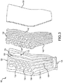
- one or more cavities 130 may be formed through blade body 110. Cavities 130 may be formed by removing material from a surface of blade body 110, such as by machining, milling, electrochemical machining (ECM), electrical discharge machining (EDM) or other suitable process. Cavities 130 are shown in FIG. 3 as being formed in a surface of blade body 110, which may be a suction surface or a pressure surface of fan blade 102.
- An inner surface 132 of blade body 110 may define a cavity 130.
- a plurality of cavities 130 may further be defined by stiffening walls or ribs 134.
- Cavities 130 may comprise a plurality of pockets or channels separated by ribs 134.
- ribs 134 may be formed on internal surface 132 of blade body 110 and may define cavities 130. Ribs 134 may reinforce fan blade 102 and may allow the outer surfaces of fan blade 102 to be made thinner, thus saving weight. The particular design of ribs 134 may depend on several factors but may typically be directed toward balancing weight reduction and manufacturing costs.
- cavities 130 may be filled wholly or partially with a blade filler 140.
- the blade filler 140 may be a structural filler material that may be bonded to blade body 110 to form a part of the fan blade 102.
- a plurality of pre-formed strips or pieces of a blade filler 140 may each be sized to fit within one of the plurality of cavities 130.
- Blade filler 140 may at least partially fill one or more cavities 130 between adjacent ribs 134.
- blade filler 140 may include a plurality of bumps 142 formed integrally on one or more surfaces of blade filler 140.
- a blade cover 150 may be placed over cavities 130 to form an aerodynamic flow surface over cavities 130.
- blade cover 150 may be fabricated from titanium, titanium alloy, aluminum, aluminum alloy, composite material or other suitable structural materials.
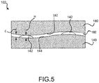
- blade filler 140 may be glued, bonded, or otherwise coupled to blade body 110 and/or blade cover 150. Referring momentarily to FIG. 5 and with continued reference to FIG. 3 , an adhesive 160 may be used to bond the blade filler 140 with bumps 142 to inner surface 132 of blade body 110, ribs 134, and/or blade cover 150.
- blade filler 140 may conform to the inner surface 132 of blade body 110 and to an inner surface of blade cover 150. Blade filler 140 may prevent inward distortion (i.e., inward toward cavity 130) of the surfaces of blade body 110 and blade cover 150 and may increase the ability of the fan blade 102 to carry shear load. Blade filler 140 may provide additional surface area to which the blade cover 150 can contact, mate, and/or bond. In various embodiments, blade filler 140 may comprise a geometry that is complementary to the geometry of cavities 130. Although the blade body 110, cavities 130, ribs 134, blade filler 140 and blade cover 150 of fan blade 102 are shown as having certain relative dimensions, such dimensions are only exemplary and other relative dimensions are possible.
- Blade filler 140 may include a low density filler or another lightweight material, such as a foam.
- Blade filler 140 may comprise a material having a lower density than, for example, the material of blade body 110.
- blade filler 140 may comprise a polymer foam, such as polyethylene or polyurethane foam, a metallic foam, such as aluminum foam, or other suitable materials.
- Blade filler 140 may comprise, for example, a closed cell foam, such as closed cell polyurethane foam.
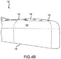
- blade filler 140 includes bumps 142 formed on a first surface 144 of blade filler 140. First surface 144 may comprise a bonding surface of blade filler 140.
- a bump 142 comprises raised feature such as a bump or a ridge formed on or integrated onto first surface 144 of blade filler 140.
- One or more surfaces of blade filler 140 may not include bumps 142, such as a second surface 146 of blade filler 140.
- Second surface 146 may comprise a non-bonding surface of blade filler 140.
- Blade filler 140 may comprise various non-planar surfaces, wherein a non-planar surface may be a surface that is not flat.
- a non-bonding surface, such as second surface 146 of blade filler 140 may be a portion or extension of a bonding surface, such as a first surface 144 with bumps 142. As illustrated in FIG.
- second surface 146 without bumps 142 may include edge surfaces of a piece of blade filler 140 adjacent to first surface 144 with bumps 142. It will be understood that various bonding surfaces and non-bonding surfaces of blade filler 140 may include bumps 142. According to the invention, bumps 142 are integrally formed with blade filler 140. As used herein, the term “integrated” or “integral” may include forming one, single continuous piece. Bumps 142 may, for example, be molded with blade filler 140, or machined into first surface 144, depending on the blade filler 140 fabrication method. Blade filler 140 and bumps 142 may be made from moldable materials.
- blade filler 140 with bumps 142 may be compression molded using an autoclave or injection molded by injecting material into a mold.
- Blade filler 140 and bumps 142 may be formed by a subtractive manufacturing process such as casting, forging, milling, grinding, machining, and the like. Blade filler 140 and bumps 142 may also be formed by additive manufacturing.
- a base of bumps 142 may have a width or radius R of about 2 millimeters (0.08 inches), wherein "about” in this context only means +/- 1 millimeter (mm) (0.04 inches). Radius R of bumps 142 may be between 1.52 mm (0.06 inches) to 2.54 mm (0.10 inches), and further between 1.78 mm (0.07 inches) to 2.29 mm (0.09 inches). Bumps 142 may include various shapes, such as semi-spherical, dome, pyramid, conical or other geometric shape. Bumps 142 are illustrated in FIG. 4A as having a round base shape, however it will be understood that a base of each bump may be round, oval, triangular, rectangular, or other shape.
- a density of bumps 142 across first surface 144 may vary, i.e., a distance between adjacent bumps 142 may be various distances, and may depend on a size and shape of the surface, material type, adhesive type and/or other design considerations.
- Bumps 142 may or may not be uniformly spaced apart, such that portions of first surface 144 may have a greater density of bumps 142 than other portions of first surface 144.
- bumps 142 may be spaced apart by less than 2.54 mm (0.10 inches) to 10 mm (0.39 inches), by less than 20 mm (0.79 inches), or may be spaced apart by less than or greater than 25.4 mm (1 inch).
- bumps 142 are formed on a bonding surface, such as first surface 144, of blade filler 140.
- Non-bonding surfaces of 9 blade filler 140 such as second surface 146, may or may not include bumps 142.
- a third surface 148 of blade filler 140 which may be opposite to first surface 144, may comprise a non-bonding surface of blade filler 140 and may or may not include bumps 142.
- Each of bumps 142 may generally have a uniform height and may generally follow a contour of first surface 144, such that blade filler 140 with bumps 142 fits the shape of its corresponding cavity 130 in blade body 110 (see FIG. 3 ).
- Bumps 142 may increase a surface area of first surface 144, thereby improving bonding first surface 144.
- bumps 142 may have a semi-spherical or dome-shaped geometry, or other shape. A shape of bumps 142 may allow blade filler 140 to be molded and subsequently removed from the mold more easily. By incorporating the bumps 142 or surface features of blade filler 140 into a mold, the cost of assembling fan blade 102 with blade filler 140 may be reduced.
- Blade filler 140 may be bonded to a fan blade component 180, which may be blade body 110 or blade cover 150.
- First surface 144 of blade filler 140 with bumps 142 may be bonded to a bonding surface 182 of the fan blade component 180.
- the bonding surface 182 of the fan blade component 180 may comprise an inner surface 132 of a cavity 130 of blade body 110.
- blade filler 140 may be bonded to fan blade component 180 by an adhesive 160.
- Adhesive 160 may include a urethane-based adhesive, polyurethane-based adhesive, epoxy-based adhesive, epoxy film, rubber adhesive or other suitable adhesive. Adhesive 160 may be applied to first surface 144 of blade filler 140 or to the bonding surface 182 of fan blade component 180. Heat and pressure may be applied to cure adhesive 160 to bond blade filler 140 to fan blade component 180.
- bumps 142 formed on first surface 144 may have a height H as measured from first surface 144 to a tip of bump 142 (see FIG. 5 ) which may further be a bonding surface.
- Bumps may include a height H of about of about 0.25 mm (0.01 inches), wherein "about” in this context only means +/- 0.1 mm (0.004 inches).
- Height H of bumps 142 may be between 0.025 mm (0.001 inches) and 0.76 mm (0.03 inches), and further between 0.13 mm (0.005 inches) and 0.51 mm (0.02 inches), and further between 0.20 mm (0.008 inches) to 0.30 mm (0.012 inches).
- a clearance C is defined between first surface 144 of blade filler 140 and bonding surface 182 of fan blade component 180 by the height H of bumps 142. Bonding surface 182 of fan blade component 180 contacts bumps 142, and does not directly contact first surface 144 of blade filler 140. Bumps 142 provide clearance C for adhesive 160 to fit between fan blade component 180 and blade filler 140, with adhesive 160 formed around bumps 142. Thus, adhesive 160 may remain between fan blade component 180 and blade filler 140 during the application of heat and pressure for bonding. The height of the bumps 142 sets the adhesive 160 layer thickness and reduces areas of direct contact between blade filler 140 and the bonding surface 182 of the fan blade component 180 and the pushing out of adhesive 160 during the adhesive cure process. Bumps 142 integrated onto the bonding surfaces of blade filler 140 may eliminate the need for a scrim separator between first surface 144 of blade filler 140 and bonding surface 182 of fan blade component 180.
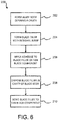
- Method 200 may include the step of forming a blade body defining a cavity (step 202), forming a blade filler with an integral bump (step 204), applying an adhesive to the blade filler or to the fan blade component (step 206), disposing the blade filler in the cavity of the blade body (step 208), and bonding the blade filler to the fan blade component (step 210).
- Step 204 may further include machining integral bumps on blade filler 140 or molding integral bumps, such as bumps 142, with blade filler 140.
- Blade filler 140 with bumps 142 may be compression molded using an autoclave or injection molded by injecting material into a mold.
- a mold may be formed to define outer surfaces of blade filler 140 including bumps 142.
- the mold may be a negative of a fan blade component, such as blade filler 140 with bumps 142.
- a material may be placed into the mold.
- Blade filler 140 formed of moldable materials such as polyurethane closed cell foam. The contents of the mold may undergo a curing process.
- a blade filler 140 with integral bumps may be formed using a low cost technique.
- Step 206 may further include applying adhesive 160 to a fan blade component 180, which may be the blade body 110 and/or the blade cover 150.
- Adhesive 160 may be applied to first surface 144 of fan blade filler 140 and around bumps 142 of blade filler 140.
- Adhesive 160 may be applied to a bonding surface 182 of the fan blade component 180.
- Adhesive 160 may be applied to inner surface 132 of cavity 130 of blade body 110, and/or to an inner surface of blade cover 150.
- Step 208 may further include placing a pre-formed blade filler 140, with integral bumps pre-formed on a bonding surface of blade filler 140, into cavity 130 of blade body 110.
- Step 210 may further include bonding one or more bonding surfaces of blade filler 140 to a bonding surface 182 of the fan blade component 180, which may include which may be the blade body 110 and/or the blade cover 150.
- a first surface 144 of blade filler 140, with integral bumps pre-formed on a bonding surface of blade filler 140, may be bonded to inner surface 132 of cavity 130 of blade body 110, and/or to an inner surface of blade cover 150.
Landscapes
- Engineering & Computer Science (AREA)
- Mechanical Engineering (AREA)
- General Engineering & Computer Science (AREA)
- Architecture (AREA)
- Structures Of Non-Positive Displacement Pumps (AREA)
Claims (13)
- Bläserschaufel (102) eines Gasturbinentriebwerks (20), umfassend:einen Schaufelkörper (110), beinhaltend eine Innenfläche (132), die einen Hohlraum (130) im Schaufelkörper (110) definiert;einen Schaufelfüllstoff (140), der in dem Hohlraum (130) angeordnet ist, wobei der Schaufelfüllstoff (140) Erhebungen (142) beinhaltet, die auf einer ersten Fläche (144) des Schaufelfüllstoffs (140) einstückig gebildet sind,dadurch gekennzeichnet, dass:
die Erhebungen (142) von der ersten Fläche (144) zu einer gegenüberliegenden Verbindungsfläche (182) einer Bläserschaufelkomponente (180) vorstehen, um einen Abstand (C) bereitzustellen, damit Klebstoff (160) zwischen die Bläserschaufelkomponente (180) und den Schaufelfüllstoff (140) um die Erhebungen (142) passt. - Bläserschaufel (102) nach Anspruch 1, ferner umfassend einen Klebstoff (160), der auf der ersten Fläche (144) des Schaufelfüllstoffs (140) gebildet ist.
- Bläserschaufel (102) nach Anspruch 1 oder 2, wobei die erste Fläche (144) des Schaufelfüllstoffs (140) an die Innenfläche (132) des Schaufelkörpers (110) gebunden ist.
- Bläserschaufel (102) nach Anspruch 1, 2 oder 3, wobei die erste Fläche (144) des Schaufelfüllstoffs (140) eine nicht ebene Oberfläche umfasst.
- Bläserschaufel (102) nach einem der vorhergehenden Ansprüche, wobei die Erhebung (142) eine Höhe (H) zwischen 0,20 mm (0,008 Zoll) und 0,30 mm (0,012 Zoll) aufweist.
- Bläserschaufel (102) nach einem der vorhergehenden Ansprüche, ferner umfassend eine Schaufelabdeckung (150), die über dem Schaufelfüllstoff (140) und dem Hohlraum (130) angeordnet ist.
- Bläserschaufel (102) nach Anspruch 6, wobei die erste Fläche (144) des Schaufelfüllstoffs (140) an die Schaufelabdeckung (150) gebunden ist.
- Bläserschaufel (102) nach einem der vorhergehenden Ansprüche, wobei ein Material des Schaufelfüllstoffs (140) einen Polyurethanschaumstoff mit geschlossenen Zellen umfasst.
- Bläserabschnitt (22) eines Gasturbinentriebwerks (20), umfassend die Bläserschaufel (102) nach einem der vorhergehenden Ansprüche, die dazu konfiguriert ist, um eine Achse (A-A') zu rotieren.
- Verfahren zum Bilden einer Bläserschaufel (102), umfassend:Bilden eines Schaufelkörpers (110), beinhaltend eine Innenfläche (132), die einen Hohlraum (130) definiert;Bilden eines Schaufelfüllstoffs (140), beinhaltend eine erste Fläche (144) mit einstückigen Erhebungen (142);Anordnen des Schaufelfüllstoffs (140) im Hohlraum (130); undBinden der ersten Fläche (144) des Schaufelfüllstoffs (140) an eine Bläserschaufelkomponente (180),dadurch gekennzeichnet, dass:
die Erhebungen (142) von der ersten Fläche (144) zu einer gegenüberliegenden Fläche (182) einer Bläserschaufelkomponente (180) vorstehen, um einen Abstand (C) bereitzustellen, damit Klebstoff (160) zwischen die Bläserschaufelkomponente (180) und den Schaufelfüllstoff (140) um die Erhebungen (142) passt. - Verfahren nach Anspruch 10, ferner umfassend Auftragen eines Klebstoffs (160) auf mindestens eines von der Bläserschaufelkomponente (180) oder der ersten Fläche (144) des Schaufelfüllstoffs (140).
- Verfahren nach Anspruch 10 oder 11, wobei die Bläserschaufelkomponente (180) mindestens eines von dem Schaufelkörper (110) oder einer Schaufelabdeckung (150) beinhaltet.
- Verfahren nach Anspruch 10, 11 oder 12, wobei das Bilden des Schaufelfüllstoffs (140) ferner mindestens eines von Formpressen oder Spritzgießen des Schaufelfüllstoffs (140) und der einstückigen Erhebung (142) umfasst.
Applications Claiming Priority (1)
| Application Number | Priority Date | Filing Date | Title |
|---|---|---|---|
| US15/189,685 US20170370375A1 (en) | 2016-06-22 | 2016-06-22 | Fan blade filler |
Publications (2)
| Publication Number | Publication Date |
|---|---|
| EP3260659A1 EP3260659A1 (de) | 2017-12-27 |
| EP3260659B1 true EP3260659B1 (de) | 2019-09-11 |
Family
ID=59152725
Family Applications (1)
| Application Number | Title | Priority Date | Filing Date |
|---|---|---|---|
| EP17177470.6A Active EP3260659B1 (de) | 2016-06-22 | 2017-06-22 | Bläserschaufelfüllstoff |
Country Status (2)
| Country | Link |
|---|---|
| US (1) | US20170370375A1 (de) |
| EP (1) | EP3260659B1 (de) |
Cited By (1)
| Publication number | Priority date | Publication date | Assignee | Title |
|---|---|---|---|---|
| EP4286651A1 (de) * | 2022-06-03 | 2023-12-06 | RTX Corporation | Bläserschaufel mit hohlen hohlräumen, die mit polymerschaumstoffe gefüllt sind |
Families Citing this family (4)
| Publication number | Priority date | Publication date | Assignee | Title |
|---|---|---|---|---|
| US20160177732A1 (en) * | 2014-07-22 | 2016-06-23 | United Technologies Corporation | Hollow fan blade for a gas turbine engine |
| US20180038386A1 (en) * | 2016-08-08 | 2018-02-08 | United Technologies Corporation | Fan blade with composite cover |
| US20200300093A1 (en) * | 2019-03-22 | 2020-09-24 | United Technologies Corporation | Method of manufacturing a multi-component article |
| US20240309764A1 (en) * | 2023-03-14 | 2024-09-19 | Raytheon Technologies Corporation | Altering structural response of two-piece hollow-vane assembly |
Family Cites Families (23)
| Publication number | Priority date | Publication date | Assignee | Title |
|---|---|---|---|---|
| US6884507B2 (en) * | 2001-10-05 | 2005-04-26 | General Electric Company | Use of high modulus, impact resistant foams for structural components |
| US7495862B2 (en) * | 2005-02-08 | 2009-02-24 | Seagate Technology Llc | Formed parts for adhesive height setting |
| US20070261224A1 (en) * | 2006-05-11 | 2007-11-15 | Dow Global Technologies Inc. | Methods and articles in having a fringed microprotrusion surface structure |
| GB0808840D0 (en) * | 2008-05-15 | 2008-06-18 | Rolls Royce Plc | A compound structure |
| US8083489B2 (en) * | 2009-04-16 | 2011-12-27 | United Technologies Corporation | Hybrid structure fan blade |
| GB0917229D0 (en) * | 2009-10-02 | 2009-11-18 | Rolls Royce Plc | Hollow turbine blade |
| US20110211965A1 (en) * | 2010-02-26 | 2011-09-01 | United Technologies Corporation | Hollow fan blade |
| US9587645B2 (en) * | 2010-09-30 | 2017-03-07 | Pratt & Whitney Canada Corp. | Airfoil blade |
| US8601691B2 (en) * | 2011-04-27 | 2013-12-10 | General Electric Company | Component and methods of fabricating a coated component using multiple types of fillers |
| DE102011112817A1 (de) * | 2011-09-12 | 2013-03-14 | Brose Fahrzeugteile GmbH & Co. Kommanditgesellschaft, Würzburg | Elektromotor, insbesondere Kühlerlüftermotor |
| US8807924B2 (en) * | 2011-09-23 | 2014-08-19 | United Technologies Corporation | Fan blade channel termination |
| US8763360B2 (en) * | 2011-11-03 | 2014-07-01 | United Technologies Corporation | Hollow fan blade tuning using distinct filler materials |
| US20130220536A1 (en) * | 2012-02-29 | 2013-08-29 | Michael Parkin | Method of applying liquid adhesive to a surface of a metallic fan blade |
| US9453418B2 (en) * | 2012-12-17 | 2016-09-27 | United Technologies Corporation | Hollow airfoil with composite cover and foam filler |
| CN105473870B (zh) * | 2013-08-19 | 2017-10-03 | 株式会社Ihi | 复合材料翼 |
| US10458428B2 (en) * | 2013-09-09 | 2019-10-29 | United Technologies Corporation | Fan blades and manufacture methods |
| EP3137281B1 (de) * | 2014-05-01 | 2021-08-04 | LM WP Patent Holding A/S | System und verfahren zur herstellung einer windturbinenschaufel |
| US9339701B2 (en) * | 2014-06-20 | 2016-05-17 | Nike, Inc. | Golf club with removable weight |
| US10960929B2 (en) * | 2014-07-02 | 2021-03-30 | Divergent Technologies, Inc. | Systems and methods for vehicle subassembly and fabrication |
| EP3164260B1 (de) * | 2014-07-02 | 2021-07-28 | Divergent Technologies, Inc. | Fahrgestell |
| US11274651B2 (en) * | 2014-08-05 | 2022-03-15 | Lm Wp Patent Holding A/S | Wind turbine blade provided with surface mounted device |
| US9759183B2 (en) * | 2015-01-05 | 2017-09-12 | General Electric Company | System and method for attaching components to a web in a wind turbine rotor blade |
| US20170101878A1 (en) * | 2015-10-08 | 2017-04-13 | General Electric Company | Low modulus insert for a component of a gas turbine engine |
-
2016
- 2016-06-22 US US15/189,685 patent/US20170370375A1/en not_active Abandoned
-
2017
- 2017-06-22 EP EP17177470.6A patent/EP3260659B1/de active Active
Non-Patent Citations (1)
| Title |
|---|
| None * |
Cited By (1)
| Publication number | Priority date | Publication date | Assignee | Title |
|---|---|---|---|---|
| EP4286651A1 (de) * | 2022-06-03 | 2023-12-06 | RTX Corporation | Bläserschaufel mit hohlen hohlräumen, die mit polymerschaumstoffe gefüllt sind |
Also Published As
| Publication number | Publication date |
|---|---|
| EP3260659A1 (de) | 2017-12-27 |
| US20170370375A1 (en) | 2017-12-28 |
Similar Documents
| Publication | Publication Date | Title |
|---|---|---|
| EP3260659B1 (de) | Bläserschaufelfüllstoff | |
| EP2589461B1 (de) | Laufschaufel mit geklebter Abdeckung | |
| EP3677749B1 (de) | Plattform in verbundbauweise mit gitterstruktur | |
| EP3044415B1 (de) | Schaufel mit einer integral versteiften verbundumhüllung | |
| US20080072569A1 (en) | Guide vane and method of fabricating the same | |
| EP2867503B1 (de) | Verkleidungsanordnung | |
| EP3279431B1 (de) | Bläserschaufel, zugehöriges herstellungsverfahren einer bläserschaufel und gasturbinentriebwerk | |
| EP3252271B1 (de) | Schaufelbausatz, zugehörige fanstufe und gasturbinentriebwerk | |
| US10823190B2 (en) | Fan blade with variable thickness composite cover | |
| EP3643885B1 (de) | Plattform für ein schaufelblatt eines gasturbinenmotors | |
| WO2014039974A1 (en) | Low radius ratio fan for a gas turbine engine | |
| EP3489463B1 (de) | Zusammengesetzte lüfterplattformlaschenverstärkung | |
| EP3736412B1 (de) | Lüfterzwischenschaufelplattform mit kern und deckschicht aus polymer-matrix-verbundwerkstoff | |
| EP3572214A1 (de) | Werkzeug und verfahren zum verbinden einer schaufel | |
| US20170023006A1 (en) | Fan blade with composite cover and structural filler | |
| EP3476721B1 (de) | Schaufel mit dämpfungsstrukturen | |
| US11879355B1 (en) | Airfoil assembly with an internal reinforcement structure |
Legal Events
| Date | Code | Title | Description |
|---|---|---|---|
| PUAI | Public reference made under article 153(3) epc to a published international application that has entered the european phase |
Free format text: ORIGINAL CODE: 0009012 |
|
| STAA | Information on the status of an ep patent application or granted ep patent |
Free format text: STATUS: THE APPLICATION HAS BEEN PUBLISHED |
|
| AK | Designated contracting states |
Kind code of ref document: A1 Designated state(s): AL AT BE BG CH CY CZ DE DK EE ES FI FR GB GR HR HU IE IS IT LI LT LU LV MC MK MT NL NO PL PT RO RS SE SI SK SM TR |
|
| AX | Request for extension of the european patent |
Extension state: BA ME |
|
| STAA | Information on the status of an ep patent application or granted ep patent |
Free format text: STATUS: REQUEST FOR EXAMINATION WAS MADE |
|
| 17P | Request for examination filed |
Effective date: 20180627 |
|
| RBV | Designated contracting states (corrected) |
Designated state(s): AL AT BE BG CH CY CZ DE DK EE ES FI FR GB GR HR HU IE IS IT LI LT LU LV MC MK MT NL NO PL PT RO RS SE SI SK SM TR |
|
| GRAP | Despatch of communication of intention to grant a patent |
Free format text: ORIGINAL CODE: EPIDOSNIGR1 |
|
| STAA | Information on the status of an ep patent application or granted ep patent |
Free format text: STATUS: GRANT OF PATENT IS INTENDED |
|
| RIC1 | Information provided on ipc code assigned before grant |
Ipc: F01D 5/14 20060101AFI20190215BHEP Ipc: F01D 5/18 20060101ALI20190215BHEP |
|
| INTG | Intention to grant announced |
Effective date: 20190322 |
|
| GRAS | Grant fee paid |
Free format text: ORIGINAL CODE: EPIDOSNIGR3 |
|
| GRAA | (expected) grant |
Free format text: ORIGINAL CODE: 0009210 |
|
| STAA | Information on the status of an ep patent application or granted ep patent |
Free format text: STATUS: THE PATENT HAS BEEN GRANTED |
|
| AK | Designated contracting states |
Kind code of ref document: B1 Designated state(s): AL AT BE BG CH CY CZ DE DK EE ES FI FR GB GR HR HU IE IS IT LI LT LU LV MC MK MT NL NO PL PT RO RS SE SI SK SM TR |
|
| REG | Reference to a national code |
Ref country code: GB Ref legal event code: FG4D |
|
| REG | Reference to a national code |
Ref country code: CH Ref legal event code: EP |
|
| REG | Reference to a national code |
Ref country code: AT Ref legal event code: REF Ref document number: 1178704 Country of ref document: AT Kind code of ref document: T Effective date: 20190915 |
|
| REG | Reference to a national code |
Ref country code: DE Ref legal event code: R096 Ref document number: 602017006881 Country of ref document: DE Ref country code: IE Ref legal event code: FG4D |
|
| REG | Reference to a national code |
Ref country code: NL Ref legal event code: MP Effective date: 20190911 |
|
| REG | Reference to a national code |
Ref country code: LT Ref legal event code: MG4D |
|
| PG25 | Lapsed in a contracting state [announced via postgrant information from national office to epo] |
Ref country code: SE Free format text: LAPSE BECAUSE OF FAILURE TO SUBMIT A TRANSLATION OF THE DESCRIPTION OR TO PAY THE FEE WITHIN THE PRESCRIBED TIME-LIMIT Effective date: 20190911 Ref country code: BG Free format text: LAPSE BECAUSE OF FAILURE TO SUBMIT A TRANSLATION OF THE DESCRIPTION OR TO PAY THE FEE WITHIN THE PRESCRIBED TIME-LIMIT Effective date: 20191211 Ref country code: HR Free format text: LAPSE BECAUSE OF FAILURE TO SUBMIT A TRANSLATION OF THE DESCRIPTION OR TO PAY THE FEE WITHIN THE PRESCRIBED TIME-LIMIT Effective date: 20190911 Ref country code: NO Free format text: LAPSE BECAUSE OF FAILURE TO SUBMIT A TRANSLATION OF THE DESCRIPTION OR TO PAY THE FEE WITHIN THE PRESCRIBED TIME-LIMIT Effective date: 20191211 Ref country code: LT Free format text: LAPSE BECAUSE OF FAILURE TO SUBMIT A TRANSLATION OF THE DESCRIPTION OR TO PAY THE FEE WITHIN THE PRESCRIBED TIME-LIMIT Effective date: 20190911 Ref country code: FI Free format text: LAPSE BECAUSE OF FAILURE TO SUBMIT A TRANSLATION OF THE DESCRIPTION OR TO PAY THE FEE WITHIN THE PRESCRIBED TIME-LIMIT Effective date: 20190911 |
|
| PG25 | Lapsed in a contracting state [announced via postgrant information from national office to epo] |
Ref country code: LV Free format text: LAPSE BECAUSE OF FAILURE TO SUBMIT A TRANSLATION OF THE DESCRIPTION OR TO PAY THE FEE WITHIN THE PRESCRIBED TIME-LIMIT Effective date: 20190911 Ref country code: RS Free format text: LAPSE BECAUSE OF FAILURE TO SUBMIT A TRANSLATION OF THE DESCRIPTION OR TO PAY THE FEE WITHIN THE PRESCRIBED TIME-LIMIT Effective date: 20190911 Ref country code: ES Free format text: LAPSE BECAUSE OF FAILURE TO SUBMIT A TRANSLATION OF THE DESCRIPTION OR TO PAY THE FEE WITHIN THE PRESCRIBED TIME-LIMIT Effective date: 20190911 Ref country code: GR Free format text: LAPSE BECAUSE OF FAILURE TO SUBMIT A TRANSLATION OF THE DESCRIPTION OR TO PAY THE FEE WITHIN THE PRESCRIBED TIME-LIMIT Effective date: 20191212 Ref country code: AL Free format text: LAPSE BECAUSE OF FAILURE TO SUBMIT A TRANSLATION OF THE DESCRIPTION OR TO PAY THE FEE WITHIN THE PRESCRIBED TIME-LIMIT Effective date: 20190911 |
|
| REG | Reference to a national code |
Ref country code: AT Ref legal event code: MK05 Ref document number: 1178704 Country of ref document: AT Kind code of ref document: T Effective date: 20190911 |
|
| PG25 | Lapsed in a contracting state [announced via postgrant information from national office to epo] |
Ref country code: NL Free format text: LAPSE BECAUSE OF FAILURE TO SUBMIT A TRANSLATION OF THE DESCRIPTION OR TO PAY THE FEE WITHIN THE PRESCRIBED TIME-LIMIT Effective date: 20190911 Ref country code: EE Free format text: LAPSE BECAUSE OF FAILURE TO SUBMIT A TRANSLATION OF THE DESCRIPTION OR TO PAY THE FEE WITHIN THE PRESCRIBED TIME-LIMIT Effective date: 20190911 Ref country code: IT Free format text: LAPSE BECAUSE OF FAILURE TO SUBMIT A TRANSLATION OF THE DESCRIPTION OR TO PAY THE FEE WITHIN THE PRESCRIBED TIME-LIMIT Effective date: 20190911 Ref country code: AT Free format text: LAPSE BECAUSE OF FAILURE TO SUBMIT A TRANSLATION OF THE DESCRIPTION OR TO PAY THE FEE WITHIN THE PRESCRIBED TIME-LIMIT Effective date: 20190911 Ref country code: RO Free format text: LAPSE BECAUSE OF FAILURE TO SUBMIT A TRANSLATION OF THE DESCRIPTION OR TO PAY THE FEE WITHIN THE PRESCRIBED TIME-LIMIT Effective date: 20190911 Ref country code: PT Free format text: LAPSE BECAUSE OF FAILURE TO SUBMIT A TRANSLATION OF THE DESCRIPTION OR TO PAY THE FEE WITHIN THE PRESCRIBED TIME-LIMIT Effective date: 20200113 Ref country code: PL Free format text: LAPSE BECAUSE OF FAILURE TO SUBMIT A TRANSLATION OF THE DESCRIPTION OR TO PAY THE FEE WITHIN THE PRESCRIBED TIME-LIMIT Effective date: 20190911 |
|
| PG25 | Lapsed in a contracting state [announced via postgrant information from national office to epo] |
Ref country code: IS Free format text: LAPSE BECAUSE OF FAILURE TO SUBMIT A TRANSLATION OF THE DESCRIPTION OR TO PAY THE FEE WITHIN THE PRESCRIBED TIME-LIMIT Effective date: 20200224 Ref country code: SK Free format text: LAPSE BECAUSE OF FAILURE TO SUBMIT A TRANSLATION OF THE DESCRIPTION OR TO PAY THE FEE WITHIN THE PRESCRIBED TIME-LIMIT Effective date: 20190911 Ref country code: CZ Free format text: LAPSE BECAUSE OF FAILURE TO SUBMIT A TRANSLATION OF THE DESCRIPTION OR TO PAY THE FEE WITHIN THE PRESCRIBED TIME-LIMIT Effective date: 20190911 Ref country code: SM Free format text: LAPSE BECAUSE OF FAILURE TO SUBMIT A TRANSLATION OF THE DESCRIPTION OR TO PAY THE FEE WITHIN THE PRESCRIBED TIME-LIMIT Effective date: 20190911 |
|
| REG | Reference to a national code |
Ref country code: DE Ref legal event code: R097 Ref document number: 602017006881 Country of ref document: DE |
|
| PLBE | No opposition filed within time limit |
Free format text: ORIGINAL CODE: 0009261 |
|
| STAA | Information on the status of an ep patent application or granted ep patent |
Free format text: STATUS: NO OPPOSITION FILED WITHIN TIME LIMIT |
|
| PG2D | Information on lapse in contracting state deleted |
Ref country code: IS |
|
| PG25 | Lapsed in a contracting state [announced via postgrant information from national office to epo] |
Ref country code: DK Free format text: LAPSE BECAUSE OF FAILURE TO SUBMIT A TRANSLATION OF THE DESCRIPTION OR TO PAY THE FEE WITHIN THE PRESCRIBED TIME-LIMIT Effective date: 20190911 Ref country code: IS Free format text: LAPSE BECAUSE OF FAILURE TO SUBMIT A TRANSLATION OF THE DESCRIPTION OR TO PAY THE FEE WITHIN THE PRESCRIBED TIME-LIMIT Effective date: 20200112 |
|
| 26N | No opposition filed |
Effective date: 20200615 |
|
| PG25 | Lapsed in a contracting state [announced via postgrant information from national office to epo] |
Ref country code: SI Free format text: LAPSE BECAUSE OF FAILURE TO SUBMIT A TRANSLATION OF THE DESCRIPTION OR TO PAY THE FEE WITHIN THE PRESCRIBED TIME-LIMIT Effective date: 20190911 |
|
| PG25 | Lapsed in a contracting state [announced via postgrant information from national office to epo] |
Ref country code: MC Free format text: LAPSE BECAUSE OF FAILURE TO SUBMIT A TRANSLATION OF THE DESCRIPTION OR TO PAY THE FEE WITHIN THE PRESCRIBED TIME-LIMIT Effective date: 20190911 |
|
| REG | Reference to a national code |
Ref country code: CH Ref legal event code: PL |
|
| PG25 | Lapsed in a contracting state [announced via postgrant information from national office to epo] |
Ref country code: LU Free format text: LAPSE BECAUSE OF NON-PAYMENT OF DUE FEES Effective date: 20200622 |
|
| REG | Reference to a national code |
Ref country code: BE Ref legal event code: MM Effective date: 20200630 |
|
| PG25 | Lapsed in a contracting state [announced via postgrant information from national office to epo] |
Ref country code: CH Free format text: LAPSE BECAUSE OF NON-PAYMENT OF DUE FEES Effective date: 20200630 Ref country code: LI Free format text: LAPSE BECAUSE OF NON-PAYMENT OF DUE FEES Effective date: 20200630 Ref country code: IE Free format text: LAPSE BECAUSE OF NON-PAYMENT OF DUE FEES Effective date: 20200622 |
|
| PG25 | Lapsed in a contracting state [announced via postgrant information from national office to epo] |
Ref country code: BE Free format text: LAPSE BECAUSE OF NON-PAYMENT OF DUE FEES Effective date: 20200630 |
|
| PG25 | Lapsed in a contracting state [announced via postgrant information from national office to epo] |
Ref country code: TR Free format text: LAPSE BECAUSE OF FAILURE TO SUBMIT A TRANSLATION OF THE DESCRIPTION OR TO PAY THE FEE WITHIN THE PRESCRIBED TIME-LIMIT Effective date: 20190911 Ref country code: MT Free format text: LAPSE BECAUSE OF FAILURE TO SUBMIT A TRANSLATION OF THE DESCRIPTION OR TO PAY THE FEE WITHIN THE PRESCRIBED TIME-LIMIT Effective date: 20190911 Ref country code: CY Free format text: LAPSE BECAUSE OF FAILURE TO SUBMIT A TRANSLATION OF THE DESCRIPTION OR TO PAY THE FEE WITHIN THE PRESCRIBED TIME-LIMIT Effective date: 20190911 |
|
| PG25 | Lapsed in a contracting state [announced via postgrant information from national office to epo] |
Ref country code: MK Free format text: LAPSE BECAUSE OF FAILURE TO SUBMIT A TRANSLATION OF THE DESCRIPTION OR TO PAY THE FEE WITHIN THE PRESCRIBED TIME-LIMIT Effective date: 20190911 |
|
| REG | Reference to a national code |
Ref country code: DE Ref legal event code: R081 Ref document number: 602017006881 Country of ref document: DE Owner name: RAYTHEON TECHNOLOGIES CORPORATION (N.D.GES.D.S, US Free format text: FORMER OWNER: UNITED TECHNOLOGIES CORPORATION, FARMINGTON, CONN., US |
|
| P01 | Opt-out of the competence of the unified patent court (upc) registered |
Effective date: 20230520 |
|
| PGFP | Annual fee paid to national office [announced via postgrant information from national office to epo] |
Ref country code: GB Payment date: 20240521 Year of fee payment: 8 |
|
| PGFP | Annual fee paid to national office [announced via postgrant information from national office to epo] |
Ref country code: DE Payment date: 20240521 Year of fee payment: 8 |
|
| PGFP | Annual fee paid to national office [announced via postgrant information from national office to epo] |
Ref country code: FR Payment date: 20240522 Year of fee payment: 8 |