EP3260434A1 - Joint surface coatings for ceramic components - Google Patents
Joint surface coatings for ceramic components Download PDFInfo
- Publication number
- EP3260434A1 EP3260434A1 EP17172477.6A EP17172477A EP3260434A1 EP 3260434 A1 EP3260434 A1 EP 3260434A1 EP 17172477 A EP17172477 A EP 17172477A EP 3260434 A1 EP3260434 A1 EP 3260434A1
- Authority
- EP
- European Patent Office
- Prior art keywords
- layer
- braze
- substrate
- component
- joining
- Prior art date
- Legal status (The legal status is an assumption and is not a legal conclusion. Google has not performed a legal analysis and makes no representation as to the accuracy of the status listed.)
- Granted
Links
Images


Classifications
-
- B—PERFORMING OPERATIONS; TRANSPORTING
- B32—LAYERED PRODUCTS
- B32B—LAYERED PRODUCTS, i.e. PRODUCTS BUILT-UP OF STRATA OF FLAT OR NON-FLAT, e.g. CELLULAR OR HONEYCOMB, FORM
- B32B18/00—Layered products essentially comprising ceramics, e.g. refractory products
-
- C—CHEMISTRY; METALLURGY
- C04—CEMENTS; CONCRETE; ARTIFICIAL STONE; CERAMICS; REFRACTORIES
- C04B—LIME, MAGNESIA; SLAG; CEMENTS; COMPOSITIONS THEREOF, e.g. MORTARS, CONCRETE OR LIKE BUILDING MATERIALS; ARTIFICIAL STONE; CERAMICS; REFRACTORIES; TREATMENT OF NATURAL STONE
- C04B37/00—Joining burned ceramic articles with other burned ceramic articles or other articles by heating
-
- B—PERFORMING OPERATIONS; TRANSPORTING
- B32—LAYERED PRODUCTS
- B32B—LAYERED PRODUCTS, i.e. PRODUCTS BUILT-UP OF STRATA OF FLAT OR NON-FLAT, e.g. CELLULAR OR HONEYCOMB, FORM
- B32B15/00—Layered products comprising a layer of metal
- B32B15/04—Layered products comprising a layer of metal comprising metal as the main or only constituent of a layer, which is next to another layer of the same or of a different material
-
- C—CHEMISTRY; METALLURGY
- C04—CEMENTS; CONCRETE; ARTIFICIAL STONE; CERAMICS; REFRACTORIES
- C04B—LIME, MAGNESIA; SLAG; CEMENTS; COMPOSITIONS THEREOF, e.g. MORTARS, CONCRETE OR LIKE BUILDING MATERIALS; ARTIFICIAL STONE; CERAMICS; REFRACTORIES; TREATMENT OF NATURAL STONE
- C04B35/00—Shaped ceramic products characterised by their composition; Ceramics compositions; Processing powders of inorganic compounds preparatory to the manufacturing of ceramic products
- C04B35/515—Shaped ceramic products characterised by their composition; Ceramics compositions; Processing powders of inorganic compounds preparatory to the manufacturing of ceramic products based on non-oxide ceramics
- C04B35/56—Shaped ceramic products characterised by their composition; Ceramics compositions; Processing powders of inorganic compounds preparatory to the manufacturing of ceramic products based on non-oxide ceramics based on carbides or oxycarbides
- C04B35/565—Shaped ceramic products characterised by their composition; Ceramics compositions; Processing powders of inorganic compounds preparatory to the manufacturing of ceramic products based on non-oxide ceramics based on carbides or oxycarbides based on silicon carbide
-
- C—CHEMISTRY; METALLURGY
- C04—CEMENTS; CONCRETE; ARTIFICIAL STONE; CERAMICS; REFRACTORIES
- C04B—LIME, MAGNESIA; SLAG; CEMENTS; COMPOSITIONS THEREOF, e.g. MORTARS, CONCRETE OR LIKE BUILDING MATERIALS; ARTIFICIAL STONE; CERAMICS; REFRACTORIES; TREATMENT OF NATURAL STONE
- C04B37/00—Joining burned ceramic articles with other burned ceramic articles or other articles by heating
- C04B37/003—Joining burned ceramic articles with other burned ceramic articles or other articles by heating by means of an interlayer consisting of a combination of materials selected from glass, or ceramic material with metals, metal oxides or metal salts
-
- C—CHEMISTRY; METALLURGY
- C04—CEMENTS; CONCRETE; ARTIFICIAL STONE; CERAMICS; REFRACTORIES
- C04B—LIME, MAGNESIA; SLAG; CEMENTS; COMPOSITIONS THEREOF, e.g. MORTARS, CONCRETE OR LIKE BUILDING MATERIALS; ARTIFICIAL STONE; CERAMICS; REFRACTORIES; TREATMENT OF NATURAL STONE
- C04B37/00—Joining burned ceramic articles with other burned ceramic articles or other articles by heating
- C04B37/003—Joining burned ceramic articles with other burned ceramic articles or other articles by heating by means of an interlayer consisting of a combination of materials selected from glass, or ceramic material with metals, metal oxides or metal salts
- C04B37/005—Joining burned ceramic articles with other burned ceramic articles or other articles by heating by means of an interlayer consisting of a combination of materials selected from glass, or ceramic material with metals, metal oxides or metal salts consisting of glass or ceramic material
-
- C—CHEMISTRY; METALLURGY
- C04—CEMENTS; CONCRETE; ARTIFICIAL STONE; CERAMICS; REFRACTORIES
- C04B—LIME, MAGNESIA; SLAG; CEMENTS; COMPOSITIONS THEREOF, e.g. MORTARS, CONCRETE OR LIKE BUILDING MATERIALS; ARTIFICIAL STONE; CERAMICS; REFRACTORIES; TREATMENT OF NATURAL STONE
- C04B37/00—Joining burned ceramic articles with other burned ceramic articles or other articles by heating
- C04B37/02—Joining burned ceramic articles with other burned ceramic articles or other articles by heating with metallic articles
- C04B37/023—Joining burned ceramic articles with other burned ceramic articles or other articles by heating with metallic articles characterised by the interlayer used
-
- C—CHEMISTRY; METALLURGY
- C04—CEMENTS; CONCRETE; ARTIFICIAL STONE; CERAMICS; REFRACTORIES
- C04B—LIME, MAGNESIA; SLAG; CEMENTS; COMPOSITIONS THEREOF, e.g. MORTARS, CONCRETE OR LIKE BUILDING MATERIALS; ARTIFICIAL STONE; CERAMICS; REFRACTORIES; TREATMENT OF NATURAL STONE
- C04B37/00—Joining burned ceramic articles with other burned ceramic articles or other articles by heating
- C04B37/02—Joining burned ceramic articles with other burned ceramic articles or other articles by heating with metallic articles
- C04B37/023—Joining burned ceramic articles with other burned ceramic articles or other articles by heating with metallic articles characterised by the interlayer used
- C04B37/025—Joining burned ceramic articles with other burned ceramic articles or other articles by heating with metallic articles characterised by the interlayer used consisting of glass or ceramic material
-
- C—CHEMISTRY; METALLURGY
- C04—CEMENTS; CONCRETE; ARTIFICIAL STONE; CERAMICS; REFRACTORIES
- C04B—LIME, MAGNESIA; SLAG; CEMENTS; COMPOSITIONS THEREOF, e.g. MORTARS, CONCRETE OR LIKE BUILDING MATERIALS; ARTIFICIAL STONE; CERAMICS; REFRACTORIES; TREATMENT OF NATURAL STONE
- C04B37/00—Joining burned ceramic articles with other burned ceramic articles or other articles by heating
- C04B37/04—Joining burned ceramic articles with other burned ceramic articles or other articles by heating with articles made from glass
- C04B37/045—Joining burned ceramic articles with other burned ceramic articles or other articles by heating with articles made from glass characterised by the interlayer used
-
- C—CHEMISTRY; METALLURGY
- C04—CEMENTS; CONCRETE; ARTIFICIAL STONE; CERAMICS; REFRACTORIES
- C04B—LIME, MAGNESIA; SLAG; CEMENTS; COMPOSITIONS THEREOF, e.g. MORTARS, CONCRETE OR LIKE BUILDING MATERIALS; ARTIFICIAL STONE; CERAMICS; REFRACTORIES; TREATMENT OF NATURAL STONE
- C04B41/00—After-treatment of mortars, concrete, artificial stone or ceramics; Treatment of natural stone
- C04B41/45—Coating or impregnating, e.g. injection in masonry, partial coating of green or fired ceramics, organic coating compositions for adhering together two concrete elements
- C04B41/4501—Coating or impregnating, e.g. injection in masonry, partial coating of green or fired ceramics, organic coating compositions for adhering together two concrete elements with preformed sheet-like elements
-
- C—CHEMISTRY; METALLURGY
- C04—CEMENTS; CONCRETE; ARTIFICIAL STONE; CERAMICS; REFRACTORIES
- C04B—LIME, MAGNESIA; SLAG; CEMENTS; COMPOSITIONS THEREOF, e.g. MORTARS, CONCRETE OR LIKE BUILDING MATERIALS; ARTIFICIAL STONE; CERAMICS; REFRACTORIES; TREATMENT OF NATURAL STONE
- C04B2235/00—Aspects relating to ceramic starting mixtures or sintered ceramic products
- C04B2235/02—Composition of constituents of the starting material or of secondary phases of the final product
- C04B2235/50—Constituents or additives of the starting mixture chosen for their shape or used because of their shape or their physical appearance
- C04B2235/52—Constituents or additives characterised by their shapes
- C04B2235/5208—Fibers
- C04B2235/5216—Inorganic
- C04B2235/524—Non-oxidic, e.g. borides, carbides, silicides or nitrides
- C04B2235/5244—Silicon carbide
-
- C—CHEMISTRY; METALLURGY
- C04—CEMENTS; CONCRETE; ARTIFICIAL STONE; CERAMICS; REFRACTORIES
- C04B—LIME, MAGNESIA; SLAG; CEMENTS; COMPOSITIONS THEREOF, e.g. MORTARS, CONCRETE OR LIKE BUILDING MATERIALS; ARTIFICIAL STONE; CERAMICS; REFRACTORIES; TREATMENT OF NATURAL STONE
- C04B2235/00—Aspects relating to ceramic starting mixtures or sintered ceramic products
- C04B2235/70—Aspects relating to sintered or melt-casted ceramic products
- C04B2235/96—Properties of ceramic products, e.g. mechanical properties such as strength, toughness, wear resistance
-
- C—CHEMISTRY; METALLURGY
- C04—CEMENTS; CONCRETE; ARTIFICIAL STONE; CERAMICS; REFRACTORIES
- C04B—LIME, MAGNESIA; SLAG; CEMENTS; COMPOSITIONS THEREOF, e.g. MORTARS, CONCRETE OR LIKE BUILDING MATERIALS; ARTIFICIAL STONE; CERAMICS; REFRACTORIES; TREATMENT OF NATURAL STONE
- C04B2235/00—Aspects relating to ceramic starting mixtures or sintered ceramic products
- C04B2235/70—Aspects relating to sintered or melt-casted ceramic products
- C04B2235/96—Properties of ceramic products, e.g. mechanical properties such as strength, toughness, wear resistance
- C04B2235/9607—Thermal properties, e.g. thermal expansion coefficient
-
- C—CHEMISTRY; METALLURGY
- C04—CEMENTS; CONCRETE; ARTIFICIAL STONE; CERAMICS; REFRACTORIES
- C04B—LIME, MAGNESIA; SLAG; CEMENTS; COMPOSITIONS THEREOF, e.g. MORTARS, CONCRETE OR LIKE BUILDING MATERIALS; ARTIFICIAL STONE; CERAMICS; REFRACTORIES; TREATMENT OF NATURAL STONE
- C04B2237/00—Aspects relating to ceramic laminates or to joining of ceramic articles with other articles by heating
- C04B2237/02—Aspects relating to interlayers, e.g. used to join ceramic articles with other articles by heating
- C04B2237/04—Ceramic interlayers
- C04B2237/08—Non-oxidic interlayers
-
- C—CHEMISTRY; METALLURGY
- C04—CEMENTS; CONCRETE; ARTIFICIAL STONE; CERAMICS; REFRACTORIES
- C04B—LIME, MAGNESIA; SLAG; CEMENTS; COMPOSITIONS THEREOF, e.g. MORTARS, CONCRETE OR LIKE BUILDING MATERIALS; ARTIFICIAL STONE; CERAMICS; REFRACTORIES; TREATMENT OF NATURAL STONE
- C04B2237/00—Aspects relating to ceramic laminates or to joining of ceramic articles with other articles by heating
- C04B2237/02—Aspects relating to interlayers, e.g. used to join ceramic articles with other articles by heating
- C04B2237/04—Ceramic interlayers
- C04B2237/08—Non-oxidic interlayers
- C04B2237/083—Carbide interlayers, e.g. silicon carbide interlayers
-
- C—CHEMISTRY; METALLURGY
- C04—CEMENTS; CONCRETE; ARTIFICIAL STONE; CERAMICS; REFRACTORIES
- C04B—LIME, MAGNESIA; SLAG; CEMENTS; COMPOSITIONS THEREOF, e.g. MORTARS, CONCRETE OR LIKE BUILDING MATERIALS; ARTIFICIAL STONE; CERAMICS; REFRACTORIES; TREATMENT OF NATURAL STONE
- C04B2237/00—Aspects relating to ceramic laminates or to joining of ceramic articles with other articles by heating
- C04B2237/02—Aspects relating to interlayers, e.g. used to join ceramic articles with other articles by heating
- C04B2237/12—Metallic interlayers
-
- C—CHEMISTRY; METALLURGY
- C04—CEMENTS; CONCRETE; ARTIFICIAL STONE; CERAMICS; REFRACTORIES
- C04B—LIME, MAGNESIA; SLAG; CEMENTS; COMPOSITIONS THEREOF, e.g. MORTARS, CONCRETE OR LIKE BUILDING MATERIALS; ARTIFICIAL STONE; CERAMICS; REFRACTORIES; TREATMENT OF NATURAL STONE
- C04B2237/00—Aspects relating to ceramic laminates or to joining of ceramic articles with other articles by heating
- C04B2237/02—Aspects relating to interlayers, e.g. used to join ceramic articles with other articles by heating
- C04B2237/12—Metallic interlayers
- C04B2237/122—Metallic interlayers based on refractory metals
-
- C—CHEMISTRY; METALLURGY
- C04—CEMENTS; CONCRETE; ARTIFICIAL STONE; CERAMICS; REFRACTORIES
- C04B—LIME, MAGNESIA; SLAG; CEMENTS; COMPOSITIONS THEREOF, e.g. MORTARS, CONCRETE OR LIKE BUILDING MATERIALS; ARTIFICIAL STONE; CERAMICS; REFRACTORIES; TREATMENT OF NATURAL STONE
- C04B2237/00—Aspects relating to ceramic laminates or to joining of ceramic articles with other articles by heating
- C04B2237/02—Aspects relating to interlayers, e.g. used to join ceramic articles with other articles by heating
- C04B2237/16—Silicon interlayers
-
- C—CHEMISTRY; METALLURGY
- C04—CEMENTS; CONCRETE; ARTIFICIAL STONE; CERAMICS; REFRACTORIES
- C04B—LIME, MAGNESIA; SLAG; CEMENTS; COMPOSITIONS THEREOF, e.g. MORTARS, CONCRETE OR LIKE BUILDING MATERIALS; ARTIFICIAL STONE; CERAMICS; REFRACTORIES; TREATMENT OF NATURAL STONE
- C04B2237/00—Aspects relating to ceramic laminates or to joining of ceramic articles with other articles by heating
- C04B2237/30—Composition of layers of ceramic laminates or of ceramic or metallic articles to be joined by heating, e.g. Si substrates
-
- C—CHEMISTRY; METALLURGY
- C04—CEMENTS; CONCRETE; ARTIFICIAL STONE; CERAMICS; REFRACTORIES
- C04B—LIME, MAGNESIA; SLAG; CEMENTS; COMPOSITIONS THEREOF, e.g. MORTARS, CONCRETE OR LIKE BUILDING MATERIALS; ARTIFICIAL STONE; CERAMICS; REFRACTORIES; TREATMENT OF NATURAL STONE
- C04B2237/00—Aspects relating to ceramic laminates or to joining of ceramic articles with other articles by heating
- C04B2237/30—Composition of layers of ceramic laminates or of ceramic or metallic articles to be joined by heating, e.g. Si substrates
- C04B2237/32—Ceramic
- C04B2237/34—Oxidic
- C04B2237/341—Silica or silicates
-
- C—CHEMISTRY; METALLURGY
- C04—CEMENTS; CONCRETE; ARTIFICIAL STONE; CERAMICS; REFRACTORIES
- C04B—LIME, MAGNESIA; SLAG; CEMENTS; COMPOSITIONS THEREOF, e.g. MORTARS, CONCRETE OR LIKE BUILDING MATERIALS; ARTIFICIAL STONE; CERAMICS; REFRACTORIES; TREATMENT OF NATURAL STONE
- C04B2237/00—Aspects relating to ceramic laminates or to joining of ceramic articles with other articles by heating
- C04B2237/30—Composition of layers of ceramic laminates or of ceramic or metallic articles to be joined by heating, e.g. Si substrates
- C04B2237/32—Ceramic
- C04B2237/34—Oxidic
- C04B2237/343—Alumina or aluminates
-
- C—CHEMISTRY; METALLURGY
- C04—CEMENTS; CONCRETE; ARTIFICIAL STONE; CERAMICS; REFRACTORIES
- C04B—LIME, MAGNESIA; SLAG; CEMENTS; COMPOSITIONS THEREOF, e.g. MORTARS, CONCRETE OR LIKE BUILDING MATERIALS; ARTIFICIAL STONE; CERAMICS; REFRACTORIES; TREATMENT OF NATURAL STONE
- C04B2237/00—Aspects relating to ceramic laminates or to joining of ceramic articles with other articles by heating
- C04B2237/30—Composition of layers of ceramic laminates or of ceramic or metallic articles to be joined by heating, e.g. Si substrates
- C04B2237/32—Ceramic
- C04B2237/36—Non-oxidic
-
- C—CHEMISTRY; METALLURGY
- C04—CEMENTS; CONCRETE; ARTIFICIAL STONE; CERAMICS; REFRACTORIES
- C04B—LIME, MAGNESIA; SLAG; CEMENTS; COMPOSITIONS THEREOF, e.g. MORTARS, CONCRETE OR LIKE BUILDING MATERIALS; ARTIFICIAL STONE; CERAMICS; REFRACTORIES; TREATMENT OF NATURAL STONE
- C04B2237/00—Aspects relating to ceramic laminates or to joining of ceramic articles with other articles by heating
- C04B2237/30—Composition of layers of ceramic laminates or of ceramic or metallic articles to be joined by heating, e.g. Si substrates
- C04B2237/32—Ceramic
- C04B2237/36—Non-oxidic
- C04B2237/363—Carbon
-
- C—CHEMISTRY; METALLURGY
- C04—CEMENTS; CONCRETE; ARTIFICIAL STONE; CERAMICS; REFRACTORIES
- C04B—LIME, MAGNESIA; SLAG; CEMENTS; COMPOSITIONS THEREOF, e.g. MORTARS, CONCRETE OR LIKE BUILDING MATERIALS; ARTIFICIAL STONE; CERAMICS; REFRACTORIES; TREATMENT OF NATURAL STONE
- C04B2237/00—Aspects relating to ceramic laminates or to joining of ceramic articles with other articles by heating
- C04B2237/30—Composition of layers of ceramic laminates or of ceramic or metallic articles to be joined by heating, e.g. Si substrates
- C04B2237/32—Ceramic
- C04B2237/36—Non-oxidic
- C04B2237/365—Silicon carbide
-
- C—CHEMISTRY; METALLURGY
- C04—CEMENTS; CONCRETE; ARTIFICIAL STONE; CERAMICS; REFRACTORIES
- C04B—LIME, MAGNESIA; SLAG; CEMENTS; COMPOSITIONS THEREOF, e.g. MORTARS, CONCRETE OR LIKE BUILDING MATERIALS; ARTIFICIAL STONE; CERAMICS; REFRACTORIES; TREATMENT OF NATURAL STONE
- C04B2237/00—Aspects relating to ceramic laminates or to joining of ceramic articles with other articles by heating
- C04B2237/30—Composition of layers of ceramic laminates or of ceramic or metallic articles to be joined by heating, e.g. Si substrates
- C04B2237/32—Ceramic
- C04B2237/36—Non-oxidic
- C04B2237/368—Silicon nitride
-
- C—CHEMISTRY; METALLURGY
- C04—CEMENTS; CONCRETE; ARTIFICIAL STONE; CERAMICS; REFRACTORIES
- C04B—LIME, MAGNESIA; SLAG; CEMENTS; COMPOSITIONS THEREOF, e.g. MORTARS, CONCRETE OR LIKE BUILDING MATERIALS; ARTIFICIAL STONE; CERAMICS; REFRACTORIES; TREATMENT OF NATURAL STONE
- C04B2237/00—Aspects relating to ceramic laminates or to joining of ceramic articles with other articles by heating
- C04B2237/30—Composition of layers of ceramic laminates or of ceramic or metallic articles to be joined by heating, e.g. Si substrates
- C04B2237/32—Ceramic
- C04B2237/38—Fiber or whisker reinforced
-
- C—CHEMISTRY; METALLURGY
- C04—CEMENTS; CONCRETE; ARTIFICIAL STONE; CERAMICS; REFRACTORIES
- C04B—LIME, MAGNESIA; SLAG; CEMENTS; COMPOSITIONS THEREOF, e.g. MORTARS, CONCRETE OR LIKE BUILDING MATERIALS; ARTIFICIAL STONE; CERAMICS; REFRACTORIES; TREATMENT OF NATURAL STONE
- C04B2237/00—Aspects relating to ceramic laminates or to joining of ceramic articles with other articles by heating
- C04B2237/50—Processing aspects relating to ceramic laminates or to the joining of ceramic articles with other articles by heating
- C04B2237/52—Pre-treatment of the joining surfaces, e.g. cleaning, machining
-
- C—CHEMISTRY; METALLURGY
- C04—CEMENTS; CONCRETE; ARTIFICIAL STONE; CERAMICS; REFRACTORIES
- C04B—LIME, MAGNESIA; SLAG; CEMENTS; COMPOSITIONS THEREOF, e.g. MORTARS, CONCRETE OR LIKE BUILDING MATERIALS; ARTIFICIAL STONE; CERAMICS; REFRACTORIES; TREATMENT OF NATURAL STONE
- C04B2237/00—Aspects relating to ceramic laminates or to joining of ceramic articles with other articles by heating
- C04B2237/50—Processing aspects relating to ceramic laminates or to the joining of ceramic articles with other articles by heating
- C04B2237/58—Forming a gradient in composition or in properties across the laminate or the joined articles
-
- C—CHEMISTRY; METALLURGY
- C04—CEMENTS; CONCRETE; ARTIFICIAL STONE; CERAMICS; REFRACTORIES
- C04B—LIME, MAGNESIA; SLAG; CEMENTS; COMPOSITIONS THEREOF, e.g. MORTARS, CONCRETE OR LIKE BUILDING MATERIALS; ARTIFICIAL STONE; CERAMICS; REFRACTORIES; TREATMENT OF NATURAL STONE
- C04B2237/00—Aspects relating to ceramic laminates or to joining of ceramic articles with other articles by heating
- C04B2237/50—Processing aspects relating to ceramic laminates or to the joining of ceramic articles with other articles by heating
- C04B2237/59—Aspects relating to the structure of the interlayer
-
- C—CHEMISTRY; METALLURGY
- C04—CEMENTS; CONCRETE; ARTIFICIAL STONE; CERAMICS; REFRACTORIES
- C04B—LIME, MAGNESIA; SLAG; CEMENTS; COMPOSITIONS THEREOF, e.g. MORTARS, CONCRETE OR LIKE BUILDING MATERIALS; ARTIFICIAL STONE; CERAMICS; REFRACTORIES; TREATMENT OF NATURAL STONE
- C04B2237/00—Aspects relating to ceramic laminates or to joining of ceramic articles with other articles by heating
- C04B2237/50—Processing aspects relating to ceramic laminates or to the joining of ceramic articles with other articles by heating
- C04B2237/70—Forming laminates or joined articles comprising layers of a specific, unusual thickness
- C04B2237/708—Forming laminates or joined articles comprising layers of a specific, unusual thickness of one or more of the interlayers
-
- C—CHEMISTRY; METALLURGY
- C04—CEMENTS; CONCRETE; ARTIFICIAL STONE; CERAMICS; REFRACTORIES
- C04B—LIME, MAGNESIA; SLAG; CEMENTS; COMPOSITIONS THEREOF, e.g. MORTARS, CONCRETE OR LIKE BUILDING MATERIALS; ARTIFICIAL STONE; CERAMICS; REFRACTORIES; TREATMENT OF NATURAL STONE
- C04B2237/00—Aspects relating to ceramic laminates or to joining of ceramic articles with other articles by heating
- C04B2237/50—Processing aspects relating to ceramic laminates or to the joining of ceramic articles with other articles by heating
- C04B2237/72—Forming laminates or joined articles comprising at least two interlayers directly next to each other
-
- C—CHEMISTRY; METALLURGY
- C04—CEMENTS; CONCRETE; ARTIFICIAL STONE; CERAMICS; REFRACTORIES
- C04B—LIME, MAGNESIA; SLAG; CEMENTS; COMPOSITIONS THEREOF, e.g. MORTARS, CONCRETE OR LIKE BUILDING MATERIALS; ARTIFICIAL STONE; CERAMICS; REFRACTORIES; TREATMENT OF NATURAL STONE
- C04B2237/00—Aspects relating to ceramic laminates or to joining of ceramic articles with other articles by heating
- C04B2237/50—Processing aspects relating to ceramic laminates or to the joining of ceramic articles with other articles by heating
- C04B2237/84—Joining of a first substrate with a second substrate at least partially inside the first substrate, where the bonding area is at the inside of the first substrate, e.g. one tube inside another tube
Definitions
- the present disclosure generally relates to joining ceramic components, for example, ceramic matrix composite components.
- Ceramic materials may be used for aerospace, automotive, aviation, and industrial applications due to their desirable high temperature properties.
- a ceramic matrix composite is a fibre-reinforced ceramic structure that features ceramic matrices toughened by incorporating reinforcement materials, such as fibres.
- Industrial components may be fabricated by joining ceramic or CMC components to other components.
- components of high temperature mechanical systems, such as gas turbine engines, may include ceramic or CMC subcomponents.
- an article comprising a component, a substrate comprising a first ceramic material, a joining layer between the component and the substrate and a joint surface coating between the substrate and the joining layer.
- the joint surface coating comprises a diffusion barrier layer comprising a second ceramic material, and a compliance layer comprising at least one of a metal or a metalloid.
- the compliance layer is between the diffusion barrier layer and the substrate.
- the joining layer may comprise at least one of a braze or a weld.
- the joining layer may comprise a silicon alloy.
- the substrate may comprise a ceramic matrix composite.
- the compliance layer may comprise silicon.
- the compliance layer may consist essentially of silicon.
- the diffusion barrier layer may comprise silicon carbide.
- the diffusion barrier layer may consist essentially of silicon carbide.
- the diffusion barrier layer may be configured to inhibit the diffusion of at least one of SiC, Si 3 N 4 , or WC between the substrate and the joining layer.
- the article may further comprise a braze compatibility layer (30).
- the braze compatibility layer may comprise at least one of a metal, a metalloid or a ceramic.
- the braze compatibility layer may be configured to promote wetting of the joint surface coating with a braze material.
- the braze compatibility layer may comprise one or more of Mo, W, Ni, Ti, or SiC.
- the braze compatibility layer and the diffusion barrier layer may be the same layer.
- a method comprising: applying a compliance layer comprising at least one of a metal or a metalloid to a major surface of a substrate comprising a first ceramic material; and applying a diffusion barrier layer comprising a second ceramic material on the compliance layer.
- the method may further comprise applying a braze compatibility layer.
- the braze compatibility layer may comprise a metal, a metalloid, or a ceramic.
- the braze compatibility layer may be applied on the diffusion barrier layer.
- the diffusion barrier layer may comprise silicon carbide.
- the compliance layer may comprise silicon.
- the method may further comprise machining the major surface of the substrate.
- the method may produce a coated component.
- the method may further comprise joining a second component to the coated component.
- the second component may be joined to the coated component. This may be achieved by applying a joining layer between the second component and the substrate.
- the second component may be joined to the coated component by: holding a first joining surface of the coated component adjacent a second joining surface of the second component; heating at least one of the coated component, the second component, and a braze material; and brazing the coated component by allowing the braze material to flow in a region between the first joining surface and the second joining surface.
- Another aspect provides a method comprising: holding a first joining surface of a coated component comprising a substrate adjacent a second joining surface of a second component, wherein the substrate comprises a first ceramic coated with a joint surface coating, wherein the joint surface coating comprises a diffusion barrier layer and a compliance layer, wherein the diffusion barrier layer comprises a second ceramic, wherein the compliance layer comprises at least one of a metal or a metalloid, wherein the compliance layer is between the diffusion barrier layer and the substrate; heating at least one of the coated component, the second component, and a braze material; and brazing the coated component by allowing the braze material to flow in a region between the first joining surface and the second joining surface.
- the method may comprise joining the second component to the coated component.
- the joint surface coating may comprise a braze compatibility layer comprising at least one of a metal, a metalloid, or a ceramic.
- the diffusion barrier layer may comprise silicon carbide.
- the compliance layer may comprise silicon.
- the disclosure describes example articles including joint surface coatings on ceramic substrates, example techniques for applying joint surface coatings, and example techniques for joining coated ceramic components to other components.
- Components including ceramic or ceramic matrix composite (CMC) substrates may be joined in the course of industrial techniques, for example, manufacturing or repair.
- the joining may include suitable joining techniques, for example, brazing component surfaces with a braze.
- the components Prior to the joining, the components may be machined to prepare the surface for the joining, for example, by allowing substantially even or uniform application of the braze. However, some regions of the machined surfaces may include impurities or surface features that may prevent even or uniform application of braze materials, or may disallow the application of braze materials.
- localized areas of machined surfaces of CMC substrates may include compounds or impurities that prevent braze metals, such as silicon-based braze alloys, from properly wetting and adhering to the CMC.
- braze metals such as silicon-based braze alloys
- other localized areas of the machined CMC surfaces may allow molten braze alloy or constituent elements of the braze alloy to overflow and diffuse excessively into the CMC substrate from the surface.
- a substrate may be coated with a joint surface coating that may include a barrier layer including one or more ceramics and a compatibility layer including one or more metals or metalloids between the barrier layer and the substrate.
- the example joint surface coating may provide one or more benefits, including enhancing braze wetting and adhesion, reducing or substantially preventing undesirable flow or diffusion of braze material into the bulk of the substrate, reducing or substantially preventing flow or diffusion of species from the substrate into the braze material, providing mechanical compliance for the joint system, or combinations thereof.
- FIG. 1A is a conceptual and schematic cross-sectional block diagram illustrating an example article 10a including a substrate 12 and a joint surface coating 14a .
- Substrate 12 may include a first ceramic.
- substrate 12 may include a ceramic material; a ceramic composite; a CMC, for example, a ceramic fibre-reinforced CMC; or a composite including ceramic and one or more of glass, metal, or polymer.
- Example ceramic materials may include, for example, silicon carbide (SiC); silicon nitride (Si 3 N 4 ); alumina (Al 2 O 3 ); aluminosilicate; silica (SiO 2 ); transition metal carbides, silicides, or both (e.g.
- substrate 12 additionally may include silicon metal, carbon, or the like.
- substrate 12 may include mixtures of two or more of SiC, Si 3 N 4 , Al 2 O 3 , aluminosilicate, silica, silicon metal, carbon, or the like.
- substrate 12 includes a matrix material and a reinforcement material.
- the matrix material includes a ceramic material alone or in combination with a metal, such as, for example, SiC alone or in combination with silicon metal, or other ceramics described herein.
- the CMC may further include a continuous or discontinuous reinforcement material.
- the reinforcement material may include discontinuous whiskers, platelets, fibres, or particulates.
- the reinforcement material may include a continuous monofilament or multifilament weave.
- the reinforcement material may include SiC, C, other ceramic materials described herein, or the like.
- substrate 12 includes a SiC-SiC ceramic matrix composite.
- Substrate 12 may include a surface region or a major surface 13 on which joint surface coating 14a is applied.
- substrate 12 may have a flat, substantially flat, curved, or compound surface region.
- Joint surface coating 14a may be disposed on major surface 13 of substrate 12 .
- joint surface coating 14a may be disposed evenly having a substantially uniform thickness along major surface 13 of substrate 12 .
- joint surface coating 14a may be deposited in a predetermined pattern, for example, a grid, on major surface 13 of substrate 12 , by masking or another patterning technique.
- Joint surface coating 14a may include a diffusion barrier layer 18 adjacent major surface 13 of substrate 12 and a compliance layer 16 between diffusion barrier layer 18 and substrate 12 .
- Diffusion barrier layer 18 may include a second ceramic material.
- diffusion barrier layer 18 may prevent, inhibit, or reduce the diffusion of one or more of chemical species, for example, atoms, molecules, compounds, or ions thereof to or from substrate 12 across diffusion barrier layer 18 .
- the second ceramic material in diffusion barrier layer 18 may be effective to prevent, inhibit or reduce diffusion or migration of chemical species originating from substrate 12 , or from an article adjacent substrate 12 or diffusion barrier 18 .
- diffusion barrier layer 18 may prevent the diffusion or migration of at least one of SiC, Si 3 N 4 , or WC, braze transition metals such as titanium, tantalum, aluminium, nickel, cobalt, chromium, vanadium, zirconium, niobium, or zinc, or, contaminating elements from the substrate, such as iron, boron, or oxides.
- transition metals such as titanium, tantalum, aluminium, nickel, cobalt, chromium, vanadium, zirconium, niobium, or zinc, or, contaminating elements from the substrate, such as iron, boron, or oxides.
- the second ceramic material may include any ceramic material that reduces diffusion of one or more selected components across diffusion barrier layer 18 .
- the second ceramic material may include silicon carbide.
- diffusion barrier layer 18 may consist of silicon carbide.
- diffusion barrier layer 18 may consist essentially of a layer of silicon carbide having a substantially uniform thickness of about 10 nanometres.
- a diffusion barrier layer consisting essentially of silicon carbide may prevent the diffusion or migration of species with an atomic radii larger than 87 picometres (e.g. transition metals, alkali metals, alkali earth metals, and most metalloids).
- Other bonded barrier layers that have a metallically-bonded crystallographic structure may have a higher solid solubility for the potential contaminating constituents.
- the second ceramic material in diffusion barrier layer 18 may be the same as the first ceramic material in substrate 12 , while in other examples, the second ceramic material in diffusion barrier layer 18 may be different than the first ceramic material in substrate 12 .
- a composition of the first ceramic material may be substantially the same as a composition of the second ceramic material, while including one or more additives, for example, at least one predetermined metal or metalloid element or alloy.
- diffusion barrier layer 18 may include carbon. In some examples, diffusion barrier layer 18 may not include a ceramic, and may consist of carbon.
- Joint surface coating 14a also includes compliance layer 16 .
- Compliance layer 16 may include at least one of a metal or a metalloid (e.g., at least one metal, at least one metalloid, or at least one metal and at least one metalloid).
- Compliance layer 16 reduces or substantially prevents damage caused by a thermal expansion differential between substrate 12 and diffusion barrier layer 18 .
- compliance layer 16 may have a coefficient of thermal expansion having a magnitude between respective magnitudes of coefficients of thermal expansion of substrate 12 and of diffusion barrier layer 18 . Selecting such an intermediate coefficient of thermal expansion may reduce or smoothen size change gradients across respective layers, ultimately reducing dimensional mismatch and reducing stress exerted on joint surface coating 14a .
- compliance layer 16 may at least one of prevent wear, reduce fragility, or preserve integrity of diffusion barrier layer 18.
- compliance layer 16 may assist in conforming barrier layer 18 to the geometry of substrate 12 , or in uniformly adhering barrier layer 18 to substrate 12 .
- compliance layer 16 may reduce stress applied on diffusion barrier layer 18 by substrate 12 or by a surface of an object.
- compliance layer 16 may help diffusion barrier layer 18 survive thermal, pressure, or stress cycling, for example, by dissipating heat flow and or stresses to prevent localized build-up of heat or stress that may damage diffusion barrier layer 18 .
- Compliance layer 16 may include any composition that performs the functions described herein and adheres to substrate 12 and barrier layer 18 .
- compliance layer 16 may include silicon.
- compliance layer 16 may consist of silicon.
- a compliance layer consisting essentially of silicon may provide a layer that beneficially bonds to many of the other barrier layers and bonding materials.
- compliance layer 16 may consist essentially of a layer of silicon having a substantially uniform thickness of about 10 nanometres.
- the composition of compliance layer 16 may include at least one component, for example, a metal or a metalloid, that is also present in substrate 12 .
- substrate 12 and compliance layer 16 may each include silicon.
- joint surface coating 14a may be applied over other coatings that may already be present on substrate 12 , for example, environmental barrier coatings (EBC) or thermal barrier coatings (TBC).
- EBC environmental barrier coatings
- TBC thermal barrier coatings
- Joint surface coating 14a may prevent contamination of substrate 12 and promote wetting of substrate 12 with a braze material or other joining material configured to join substrate 12 to another article.
- diffusion barrier layer 18 may reduce diffusion of chemical species between substrate 12 and an adjacent article
- compliance layer 16 may provide mechanical compliance to joint surface coating 14a by reducing thermal or other stresses resulting from thermal or mechanical cycling that may result in cracks or damage.
- joint surface coating 14a may provide a better joint between substrate 12 and an article to which component 12 is joined.
- FIG. 1B is a conceptual and schematic cross-sectional block diagram illustrating an example article 20 including a coated component 10b joined to a second component 26 by a joining layer 22 .
- Coated component 10b includes substrate 12 and a joint surface coating 14b , and may define a first joining surface 24 .
- the composition of joint surface coating 14b may be substantially similar to any of the compositions of joint surface coating 14a described with reference to FIG. 1A , and a major surface of joint surface coating 14b may be first joining surface 24 .
- Second component 26 defines a second joining surface 28 , which contacts joining layer 22 .
- FIG. 1B illustrates first and second joining surfaces 24 and 28 , and first major surface 13 , as substantially flat surfaces.
- first and second joining surfaces 24 and 28 , and first major surface 13 may define other, more complex shapes, including, for example, simple or complex curves, overhangs, undercuts, or the like.
- First and second joining surfaces 24 and 28 may define any kind of joint geometry, including, for example, at least one of a bridle joint, a butt joint, a mitre joint, a dado joint, a groove joint, a tongue and groove joint, a mortise and tenon joint, a birdsmouth joint, a halved joint, a biscuit joint, a lap joint, a double lap joint, a dovetail joint, or a splice joint. Further, first joining surface 24 and second joining surface 28 may have any complementary or corresponding geometries to define the joint geometry.
- one of the first and second joining surfaces 24 and 28 may define a mortise (a cavity) and the other of the first and second joining surface 24 and 28 may define a tenon (a projection that inserts into the mortise).
- one of the first and second joining surfaces 24 and 28 may define a half lap, a bevel lap, or the like, and the other of the first and second joining surfaces 24 and 28 may define a complementary half lap bevel lap, or the like.
- joint surface coating 14b may include additional layers compared to joint surface coating 14a illustrated in FIG. 1 , as described with reference to FIGS. 1C and 1D .
- Second component 26 may include a substrate including one or more of a metal, glass, polymer, or a substrate having a composition substantially similar to example compositions described with reference to substrate 12 of FIG. 1A .
- Second component 26 may define second joining surface 28 .
- second joining surface 28 may be a major surface of second component 26 , as shown in FIG. 1B .
- a joint surface coating (not shown) may be applied to a major surface of second component 26 , and a major surface of the joint surface coating of second component 26 may be the second joining surface 28 .
- the joint surface coating on second component 26 may include one or more layers according to examples of joint surface coating described with reference to FIGS. 1A , 1C, and 1D .
- major surface 28 may be a machined or a polished surface, or a surface otherwise prepared for joining second component 28 to coated component 10 .
- joining layer 22 may contact second joining surface 28 of second component 26 to join second component 26 to first joining surface 24 of coated component 12 .
- Joining layer 22 may include a joining material that is compatible with at least one of first joining surface 24 and second joining surface 28 .
- joining layer 22 may include a braze or a weld.
- joining layer 22 may be formed by brazing a braze material on between first joining surface 24 and second joining surface 28 .
- the braze material may originally be in the form of a powder, a paste, a preform, or any other form that may be applied on or between first joining surface 24 and second joining surface 28 . After brazing, the braze material may transform to a relatively rigid or solid layer.
- the composition of the braze material may be selected based on the composition of at least one of component 10 , or a braze compatibility layer, and second component 26 .
- a silicon-based braze material may be used to join a silicon-based ceramic/CMC to another silicon-based ceramic/CMC.
- the braze alloy may include a silicon alloy.
- joining layer 22 may consist essentially of a silicon alloy.
- any suitable silicon-based alloy may be used.
- a silicon-based alloy includes a greater amount of silicon than any other single alloying component present.
- silicon in the case of a silicon-based alloy with silicon, Ti, and Zr in the composition, silicon may be present in a greater amount that the Ti individually and also in a greater amount that the Zr individually, while the combined total of Ti and Zr may or may not be greater than the amount of silicon.
- Example alloying components include Ti, Co, C, Mo, B, V, Cr, Cu, Nb, and Zr.
- Examples of a silicon-based alloy include Si-Ti, Si-Co, Si-Ti-C, and combinations thereof.
- the braze alloy powder may include one or more high-melting point materials in addition to the Si-based alloy(s).
- the braze alloy may include one or more components having a melting-point greater than about 1400 degrees Celsius in addition to the Si-based alloy. The addition of such high melting point components may increase the amount of stable phases, such as, e.g., SiC, in joining layer 22 formed from the braze material.
- the braze material may include one or more of a binder, a filler, and a medium, for example, an aqueous medium or a suitable solvent or carrier.
- the braze material may be in the form of a tape or preform, and the binder may bind particles or powder of the braze alloy in the tape or preform.
- the binder may include an organic binder, and the organic binder may include at least one of a high char yielding component or a preceramic polymer.
- the high char yielding component may include a phenol or furan based organic material, such as furfuryl alcohol or phenol formaldehyde. The high char yielding component may act as a carbon source during the brazing technique.
- the preceramic polymer includes a polycarbosilane, which may be a precursor to SiC.
- the braze material may include the filler material, and the filler material may include a ceramic material, one or more transition metals (e.g., titanium, cobalt, molybdenum, nickel, vanadium, chromium, copper, tantalum, niobium or yttrium, zirconium), carbon, or the like.
- transition metals e.g., titanium, cobalt, molybdenum, nickel, vanadium, chromium, copper, tantalum, niobium or yttrium, zirconium
- Example ceramic materials for the filler material include transition metal carbides (e.g., molybdenum carbide, cobalt carbide, titanium carbide, tungsten carbide, vanadium carbide, niobium carbide, tantalum carbide, zirconium carbide or chromium carbide), transition metal borides (e.g., molybdenum boride, cobalt boride, titanium boride, tungsten boride, vanadium boride, niobium boride, tantalum boride, or chromium boride), transition metal silicides (e.g., titanium silicide, yttrium silicide, molybdenum silicide, or tungsten silicide), and SiC.
- transition metal carbides e.g., molybdenum carbide, cobalt carbide, titanium carbide, tungsten carbide, vanadium carbide, niobium carbide, tantalum carbide, zircon
- the filler material may include a mixture of at least two of these materials, such as SiC and a transition metal, SiC and carbon, or the like.
- the filler material may be in the form of a powder, particulate, fibre, sheet, or the like.
- the filler material may be mixed, suspended, or dispersed in a solid carrier, such as a polymer.
- the filler material may include combinations of two or more of these forms, e.g., a fibre and a powder.
- the braze material may include a powder mixed in a polymer carrier.
- the braze material may be a solid material including a filter and a metal or alloy.
- Joint surface coating 14b may promote the uniform application of joining layer 22 , for example, over major surface 13 of substrate 12 , and may prevent the diffusion of chemical species between joining layer 22 and substrate 12 , or between second component 26 and substrate 22 .
- joint surface coating 14a of FIG. 1A includes one compliance layer 16 and one diffusion barrier layer 18
- an example joint surface coating may include additional layers.
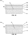
- FIG. 1C is a conceptual and schematic cross-sectional block diagram illustrating an example article 10c including substrate 12 and a joint surface coating 14c , where joint surface coating 14b includes two diffusion barrier layers and two compliance layers.
- joint surface coating 14c may include a first diffusion barrier layer 18a adjacent substrate 12 , and a first compliance layer 16a disposed between first diffusion barrier layer 18a and substrate 12 .
- Joint surface coating 14c may include a second diffusion barrier layer 18b and a second compliance layer 16b , with second compliance layer 16b disposed between second diffusion barrier layer 18b and first diffusion barrier layer 18a .
- first and second diffusion barrier layers 18a and 18b may be the same or substantially similar to any of the compositions of diffusion barrier layer 18 of FIG. 1A . In some examples, the composition of first and second diffusion barrier layers 18a and 18b may be the same, substantially the same, or different. For example, one or both first and second diffusion barrier layers 18a and 18b may include the second ceramic material. In some examples, only one of first and second diffusion barrier layers 18a and 18b may include the second ceramic material.
- the composition of first and second compliance layers 16a and 16b may be the same or substantially similar to any of the compositions of compliance layer 16 of FIG. 1A .
- the composition of first and second compliance layers 16a and 16b may be the same, substantially the same, or different.
- one or both of first and second compliance layers 16a and 16b may include the same or different metal or metalloid.
- only one of first and second compliance layers 16a and 16b may include silicon.
- both first and second compliance layers 16a and 16b may include silicon.
- joint surface coating 14c may include at least one compliance layer (e.g., one, two, or more than two compliance layers), and independently include at least one diffusion barrier layer (e.g., one, two, or more diffusion barrier layers).
- joint surface coating 14c may include a plurality of alternating diffusion barrier layers and compliance layers.
- one, two, or more than two diffusion barrier layers may be disposed between successive compliance layers.
- one, two, or more than two compliance layers may be disposed between successive diffusion barrier layers.
- each compliance layer in joint surface coating 14c may have the same or substantially the same composition, while in other examples, at least one compliance layer may have a different composition than at least one other compliance layer.
- each diffusion barrier layer in joint surface coating 14c may have the same or substantially the same composition, while in other examples, at least one diffusion barrier layer may have a different composition that at least one other diffusion barrier layer.
- Including multiple diffusion barrier layers may provide better mechanical compliance to joint surface coating 14c , by avoiding stresses that may develop in single diffusion barriers. For example, increasing the thickness of a single diffusion barrier layer may reduce diffusion of chemical species, by requiring the chemical species to migrate or diffuse across the increased thickness of the single diffusion barrier. However, increasing the thickness of the single diffusion barrier may lead to increased thermal or mechanical stresses, whereby thicker single diffusion barriers may be more prone to damage or cracking. In some examples, instead of increasing the thickness of a single diffusion barrier layer, multiple diffusion barrier layers, each having a smaller thickness, may be used, such that diffusion of chemical species would be reduced by the substantially the same effective barrier thickness.
- an example joint surface coating may additionally include a braze compatibility layer.
- FIG. 1D is a conceptual and schematic cross-sectional block diagram illustrating an example article 10d including substrate 12 and a joint surface coating 14d , where joint surface coating 14d includes a braze compatibility layer 30 .
- Braze compatibility layer 30 may act as a faying surface of a braze joint and improving wetting and adherence of the braze material in the braze joint to joint surface coating 14d or to substrate 12 , e.g., compared to an example that does not include braze compatibility layer 30 .
- braze compatibility layer 30 may be an outermost layer of joint surface coating 14d , with one or both of diffusion barrier layer 18 and compliance layer 16 disposed between braze compatibility layer 30 and substrate 12 .
- braze compatibility layer 30 may be configured to promote wetting of joint surface coating 14d with a braze material.
- braze compatibility layer 30 may promote substantially even flow and wetting (e.g., even flow and wetting or nearly even flow and wetting) of joint surface coating 14d across major surface 13 of substrate 12 with the braze material.
- braze compatibility layer 30 may include at least one of a metal, for example, a transition metal; a metalloid; or a ceramic (e.g., at least one metal; at least one metalloid; at least one ceramic; at least one metal and at least one metalloid; at least one metal and at least one ceramic; at least one metalloid and at least one ceramic; or at least one metal, at least one metalloid, and at least one ceramic).
- braze compatibility layer may include at least one of Mo, W, Ni, Ti, or SiC.
- braze compatibility layer 30 may include at least one component that is also present in the braze material that is used to join article 10d to another article.
- both braze compatibility layer 30 and the braze material may include the same metal, metalloid, or ceramic.
- both braze compatibility layer 30 and the braze material may include silicon.
- braze compatibility layer 30 and diffusion barrier layer 18 may be the same layer, i.e., a single layer may provide the functionality of both braze compatibility layer 30 and diffusion barrier layer 18 .
- diffusion barrier layer 18 may include a layer of a ceramic material that also acts as compatibility layer 30 .
- the ceramic material that provides the functionality of both braze compatibility layer 30 and diffusion barrier layer 18 may include SiC.
- the composition within a single layer may transition from a diffusion barrier composition to a braze compatibility composition.
- the concentration of silicon may increase in a gradient from a region of diffusion barrier layer 18 facing substrate 12 to a region of diffusion barrier layer 18 distant from substrate 12 .
- a second compliance layer may be disposed between braze compatibility layer 30 and diffusion barrier layer 18 of joint surface coating 14d .
- braze compatibility layer 30 may include a ceramic, and the second compliance layer may reduce or substantially prevent wear, reduce fragility, or improve integrity of braze compatibility layer 30 .
- the braze material may be compatible with diffusion barrier layer 18 , for example, the braze material may sufficiently flow, wet and adhere to diffusion barrier layer 18 , and a separate braze compatibility layer 30 may not be included.
- the respective average thicknesses of one or more layers in example joint surface coatings described with reference to FIGS. 1A to 1D above may be about 10 micrometres, for example, 10 ⁇ 5 micrometres, or 10 ⁇ 1 micrometres. In some examples, the respective thickness of each layer in example joint surface coatings may be about 10 micrometres. In some examples, the thickness of example joint surface coatings may have less than a predetermined variance, for example, have a surface variance of less than about 25 to 50 micrometres from peak to valley.
- the example articles and joint surface coatings described with reference to FIGS. 1A to1D may be prepared using any suitable technique, for example, using example techniques described with reference to FIGS. 2 and 3 .
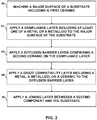
- FIG. 2 is a flow diagram illustrating an example technique for applying multilayer coating 14a to a component including substrate 12 . While the example technique of FIG. 2 is described with reference to article 10a of FIG. 1A , the example technique may be implemented to prepare other example articles according to the disclosure.
- the example technique may optionally include preparing major surface 13 of substrate 12 for coating or joining, for example, by machining major surface 13 (40) . In some examples, the machining may include one or more of etching, abrading, polishing, solvent washing, and cleaning major surface 13 .
- the example technique includes applying compliance layer 16 comprising at least one of a metal or a metalloid to major surface 14 of substrate 12 comprising a first ceramic (42) .
- the example technique further includes applying diffusion barrier layer 18 comprising the second ceramic on compliance layer 16 (44) .
- the example technique may further include applying braze compatibility layer 20 comprising a metal, a metalloid, or a ceramic on diffusion barrier layer 18 (46) .
- One or more of applying compliance layer 16 , applying diffusion barrier layer 18 , and applying braze compatibility layer 20 may be performed using similar or different suitable techniques for depositing a layer of a predetermined composition having a predetermined thickness, for example, one or more of chemical vapour deposition (CVD), physical vapour deposition (PVD), sputtering, plasma spraying, electron-beam deposition, and directed energy deposition.
- CVD chemical vapour deposition
- PVD physical vapour deposition
- sputtering plasma spraying
- electron-beam deposition electron-beam deposition
- directed energy deposition directed energy deposition.
- the example technique may optionally further include joining second component 26 to substrate 12 by applying joining layer 22 between the component and the substrate (48) .
- joining layer 22 may be applied by welding, or by brazing, as described with reference to the example technique of FIG. 3.
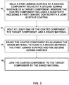
- FIG. 3 is a flow diagram illustrating an example technique for joining coated component 10 to second component 26 .
- the example technique of FIG. 3 includes positioning first joining surface 24 of coated component 10 adjacent second joining surface 28 of second component 26 (50) .
- first and second joining surfaces 24 and 28 may be positioned to define a joining region that will be occupied by the braze material.
- the example technique may include heating at least one of coated component 10 , second component 26 , and a braze material (52) .
- a braze heat source may be configured to generate energy to heat one or more of coated component 10 , second component 26 , and the braze material to a temperature sufficiently high to fuse or melt the braze material. Depending on the composition of the braze material.
- the heating may result in a temperature of greater than 700 degrees Celsius, or greater than 1000 degrees Celsius, or greater than 1200 degrees Celsius, or greater than 1400 degrees Celsius.
- the temperature may be controlled to be within an upper range that may depend on the composition of one or more of coated component 10 , second component 26 , and the braze material.
- a maximum temperature may be less than 1500 degrees Celsius, or less than 1400 degrees Celsius, or less than 1200 degrees Celsius, or less than 1000 degrees Celsius.
- one or more of coated component 10 , second component 26 , and the braze material may be preheated, postheated or both, for example, to plastically relieve stress by microcracking, grain boundary sliding or softening, dislocation motion, twinning, grain growth, recrystallization, or the like.
- the example technique of FIG. 3 also may include brazing coated component 10 by allowing the braze material to flow in a region between first joining surface 24 and second joining surface 28 (54).
- first joining surface 24 and second joining surface 28 For example, fused or molten braze material may flow or infiltrate into the joining region between first and second joining surfaces 24 and 28 by capillary action, wicking, surface tension, or other physical forces.
- braze material may be positioned in the region between first joining surface 24 and second joining surface 28 , and subsequently allowed to melt or soften to flow in the region. After the flowing, the braze material may solidify to form a solid joining layer 22 .
- the example technique may include solidifying braze material to join second component 26 to coated component 10 (56) .
- example articles and techniques are described for providing joint surface coatings on a substrate to be joined to a second component.
- the joint surface coatings may promote the joining and act as barriers to the diffusion of chemical species between the substrate and the second component, while being mechanically compliant to resist stresses that may result from thermal or mechanical cycling.
- FIG. 4 is a photograph illustrating an uncoated CMC surface having uneven brazing.
- a CMC substrate 62 was machined, and brazed with a silicon-based alloy braze 64 .
- No CMC substrate 62 was not coated before being brazed with braze 64 .
- Regions such as region 66 exhibited uneven flow of braze 64 on the brazed surface of CMC substrate 62 by braze 64 .
- Regions adjacent fibre tows 68 also exhibited uneven flow of braze 64 .
- FIG. 5 is a micrograph illustrating a cross-section of an example multilayer barrier coating on a silicon carbide substrate 72 .
- Alternating silicon layers 74 (compatibility layers) and silicon carbide layers 76 (anti-diffusion barrier ceramic layers) were deposited on the silicon carbide substrate 72 by chemical vapour deposition.
- the Vickers Hardness Number (VHN) for each layer was established by microhardness indentation.
- the Vickers Hardness Number of the respective silicon layers 74 and silicon carbide layers 76 was found to be 1200 and 3750, confirming the presence of silicon and silicon carbide in the respective layers.
Landscapes
- Chemical & Material Sciences (AREA)
- Engineering & Computer Science (AREA)
- Ceramic Engineering (AREA)
- Materials Engineering (AREA)
- Structural Engineering (AREA)
- Organic Chemistry (AREA)
- Manufacturing & Machinery (AREA)
- Ceramic Products (AREA)
Abstract
Description
- The present disclosure generally relates to joining ceramic components, for example, ceramic matrix composite components.
- Ceramic materials may be used for aerospace, automotive, aviation, and industrial applications due to their desirable high temperature properties. A ceramic matrix composite (CMC) is a fibre-reinforced ceramic structure that features ceramic matrices toughened by incorporating reinforcement materials, such as fibres. Industrial components may be fabricated by joining ceramic or CMC components to other components. For example, components of high temperature mechanical systems, such as gas turbine engines, may include ceramic or CMC subcomponents.
- In an aspect, there is therefore provided an article comprising a component, a substrate comprising a first ceramic material, a joining layer between the component and the substrate and a joint surface coating between the substrate and the joining layer. The joint surface coating comprises a diffusion barrier layer comprising a second ceramic material, and a compliance layer comprising at least one of a metal or a metalloid. The compliance layer is between the diffusion barrier layer and the substrate.
- The joining layer may comprise at least one of a braze or a weld.
- The joining layer may comprise a silicon alloy.
- The substrate may comprise a ceramic matrix composite.
- The compliance layer may comprise silicon. The compliance layer may consist essentially of silicon.
- The diffusion barrier layer may comprise silicon carbide. The diffusion barrier layer may consist essentially of silicon carbide.
- The diffusion barrier layer may be configured to inhibit the diffusion of at least one of SiC, Si3N4, or WC between the substrate and the joining layer.
- The article may further comprise a braze compatibility layer (30). The braze compatibility layer may comprise at least one of a metal, a metalloid or a ceramic. The braze compatibility layer may be configured to promote wetting of the joint surface coating with a braze material. The braze compatibility layer may comprise one or more of Mo, W, Ni, Ti, or SiC.
- The braze compatibility layer and the diffusion barrier layer may be the same layer.
- In another aspect, there is provided a method comprising: applying a compliance layer comprising at least one of a metal or a metalloid to a major surface of a substrate comprising a first ceramic material; and applying a diffusion barrier layer comprising a second ceramic material on the compliance layer.
- The method may further comprise applying a braze compatibility layer. The braze compatibility layer may comprise a metal, a metalloid, or a ceramic. The braze compatibility layer may be applied on the diffusion barrier layer.
- The diffusion barrier layer may comprise silicon carbide. The compliance layer may comprise silicon.
- The method may further comprise machining the major surface of the substrate.
- The method may produce a coated component. The method may further comprise joining a second component to the coated component.
- The second component may be joined to the coated component. This may be achieved by applying a joining layer between the second component and the substrate.
- The second component may be joined to the coated component by: holding a first joining surface of the coated component adjacent a second joining surface of the second component; heating at least one of the coated component, the second component, and a braze material; and brazing the coated component by allowing the braze material to flow in a region between the first joining surface and the second joining surface.
- Another aspect provides a method comprising: holding a first joining surface of a coated component comprising a substrate adjacent a second joining surface of a second component, wherein the substrate comprises a first ceramic coated with a joint surface coating, wherein the joint surface coating comprises a diffusion barrier layer and a compliance layer, wherein the diffusion barrier layer comprises a second ceramic, wherein the compliance layer comprises at least one of a metal or a metalloid, wherein the compliance layer is between the diffusion barrier layer and the substrate; heating at least one of the coated component, the second component, and a braze material; and brazing the coated component by allowing the braze material to flow in a region between the first joining surface and the second joining surface.
- The method may comprise joining the second component to the coated component. The joint surface coating may comprise a braze compatibility layer comprising at least one of a metal, a metalloid, or a ceramic. The diffusion barrier layer may comprise silicon carbide. The compliance layer may comprise silicon.
- The details of one or more examples are set forth in the accompanying drawings and the description below. Other features, objects, and advantages will be apparent from the description and drawings, and from the claims.
-
-
FIG. 1A is a conceptual and schematic cross-sectional block diagram illustrating an example article including a substrate and a multilayer coating; -
FIG. 1B is a conceptual and schematic cross-sectional block diagram illustrating an example article including a coated component joined to a second component; -
FIG. 1C is a conceptual and schematic cross-sectional block diagram illustrating an example article including a substrate and a multilayer coating; -
FIG. 1D is a conceptual and schematic cross-sectional block diagram illustrating an example article including a substrate and a multilayer coating; -
FIG. 2 is a flow diagram illustrating an example technique for applying a multilayer coating to a component; -
FIG. 3 is a flow diagram illustrating an example technique for joining a coated component to a second component; -
FIG. 4 is a photograph illustrating an uncoated CMC surface having uneven brazing; and -
FIG. 5 is a micrograph illustrating a cross-section of an example multilayer coating on a silicon carbide substrate. - The disclosure describes example articles including joint surface coatings on ceramic substrates, example techniques for applying joint surface coatings, and example techniques for joining coated ceramic components to other components. Components including ceramic or ceramic matrix composite (CMC) substrates may be joined in the course of industrial techniques, for example, manufacturing or repair. The joining may include suitable joining techniques, for example, brazing component surfaces with a braze. Prior to the joining, the components may be machined to prepare the surface for the joining, for example, by allowing substantially even or uniform application of the braze. However, some regions of the machined surfaces may include impurities or surface features that may prevent even or uniform application of braze materials, or may disallow the application of braze materials. For example, localized areas of machined surfaces of CMC substrates may include compounds or impurities that prevent braze metals, such as silicon-based braze alloys, from properly wetting and adhering to the CMC. In contrast, other localized areas of the machined CMC surfaces may allow molten braze alloy or constituent elements of the braze alloy to overflow and diffuse excessively into the CMC substrate from the surface.
- According to the example articles and techniques described in the disclosure, a substrate may be coated with a joint surface coating that may include a barrier layer including one or more ceramics and a compatibility layer including one or more metals or metalloids between the barrier layer and the substrate. The example joint surface coating may provide one or more benefits, including enhancing braze wetting and adhesion, reducing or substantially preventing undesirable flow or diffusion of braze material into the bulk of the substrate, reducing or substantially preventing flow or diffusion of species from the substrate into the braze material, providing mechanical compliance for the joint system, or combinations thereof.
-
FIG. 1A is a conceptual and schematic cross-sectional block diagram illustrating anexample article 10a including asubstrate 12 and ajoint surface coating 14a.Substrate 12 may include a first ceramic. For example,substrate 12 may include a ceramic material; a ceramic composite; a CMC, for example, a ceramic fibre-reinforced CMC; or a composite including ceramic and one or more of glass, metal, or polymer. Example ceramic materials may include, for example, silicon carbide (SiC); silicon nitride (Si3N4); alumina (Al2O3); aluminosilicate; silica (SiO2); transition metal carbides, silicides, or both (e.g. WC, Mo2C, TiC, MoSi2, NbSi2, TiSi2); or the like. In some examples,substrate 12 additionally may include silicon metal, carbon, or the like. In some examples,substrate 12 may include mixtures of two or more of SiC, Si3N4, Al2O3, aluminosilicate, silica, silicon metal, carbon, or the like. - In examples in which
substrate 12 includes a CMC,substrate 12 includes a matrix material and a reinforcement material. The matrix material includes a ceramic material alone or in combination with a metal, such as, for example, SiC alone or in combination with silicon metal, or other ceramics described herein. The CMC may further include a continuous or discontinuous reinforcement material. For example, the reinforcement material may include discontinuous whiskers, platelets, fibres, or particulates. In some examples, the reinforcement material may include a continuous monofilament or multifilament weave. In some examples, the reinforcement material may include SiC, C, other ceramic materials described herein, or the like. In some examples,substrate 12 includes a SiC-SiC ceramic matrix composite. -
Substrate 12 may include a surface region or amajor surface 13 on whichjoint surface coating 14a is applied. For example,substrate 12 may have a flat, substantially flat, curved, or compound surface region.Joint surface coating 14a may be disposed onmajor surface 13 ofsubstrate 12. In some examples,joint surface coating 14a may be disposed evenly having a substantially uniform thickness alongmajor surface 13 ofsubstrate 12. In other examples,joint surface coating 14a may be deposited in a predetermined pattern, for example, a grid, onmajor surface 13 ofsubstrate 12, by masking or another patterning technique. -
Joint surface coating 14a may include adiffusion barrier layer 18 adjacentmajor surface 13 ofsubstrate 12 and acompliance layer 16 betweendiffusion barrier layer 18 andsubstrate 12.Diffusion barrier layer 18 may include a second ceramic material. In some examples,diffusion barrier layer 18 may prevent, inhibit, or reduce the diffusion of one or more of chemical species, for example, atoms, molecules, compounds, or ions thereof to or fromsubstrate 12 acrossdiffusion barrier layer 18. For example, the second ceramic material indiffusion barrier layer 18 may be effective to prevent, inhibit or reduce diffusion or migration of chemical species originating fromsubstrate 12, or from an articleadjacent substrate 12 ordiffusion barrier 18. In some examples,diffusion barrier layer 18 may prevent the diffusion or migration of at least one of SiC, Si3N4, or WC, braze transition metals such as titanium, tantalum, aluminium, nickel, cobalt, chromium, vanadium, zirconium, niobium, or zinc, or, contaminating elements from the substrate, such as iron, boron, or oxides. - The second ceramic material may include any ceramic material that reduces diffusion of one or more selected components across
diffusion barrier layer 18. In some examples, the second ceramic material may include silicon carbide. In some examples,diffusion barrier layer 18 may consist of silicon carbide. In some examples,diffusion barrier layer 18 may consist essentially of a layer of silicon carbide having a substantially uniform thickness of about 10 nanometres. A diffusion barrier layer consisting essentially of silicon carbide may prevent the diffusion or migration of species with an atomic radii larger than 87 picometres (e.g. transition metals, alkali metals, alkali earth metals, and most metalloids). Other bonded barrier layers that have a metallically-bonded crystallographic structure may have a higher solid solubility for the potential contaminating constituents. In some examples, the second ceramic material indiffusion barrier layer 18 may be the same as the first ceramic material insubstrate 12, while in other examples, the second ceramic material indiffusion barrier layer 18 may be different than the first ceramic material insubstrate 12. In some examples, a composition of the first ceramic material may be substantially the same as a composition of the second ceramic material, while including one or more additives, for example, at least one predetermined metal or metalloid element or alloy. In some examples,diffusion barrier layer 18 may include carbon. In some examples,diffusion barrier layer 18 may not include a ceramic, and may consist of carbon. -
Joint surface coating 14a also includescompliance layer 16.Compliance layer 16 may include at least one of a metal or a metalloid (e.g., at least one metal, at least one metalloid, or at least one metal and at least one metalloid).Compliance layer 16 reduces or substantially prevents damage caused by a thermal expansion differential betweensubstrate 12 anddiffusion barrier layer 18. For example,compliance layer 16 may have a coefficient of thermal expansion having a magnitude between respective magnitudes of coefficients of thermal expansion ofsubstrate 12 and ofdiffusion barrier layer 18. Selecting such an intermediate coefficient of thermal expansion may reduce or smoothen size change gradients across respective layers, ultimately reducing dimensional mismatch and reducing stress exerted onjoint surface coating 14a. In some examples,compliance layer 16 may at least one of prevent wear, reduce fragility, or preserve integrity ofdiffusion barrier layer 18. For example,compliance layer 16 may assist in conformingbarrier layer 18 to the geometry ofsubstrate 12, or in uniformly adheringbarrier layer 18 tosubstrate 12. In some examples,compliance layer 16 may reduce stress applied ondiffusion barrier layer 18 bysubstrate 12 or by a surface of an object. In some examples,compliance layer 16 may helpdiffusion barrier layer 18 survive thermal, pressure, or stress cycling, for example, by dissipating heat flow and or stresses to prevent localized build-up of heat or stress that may damagediffusion barrier layer 18.Compliance layer 16 may include any composition that performs the functions described herein and adheres tosubstrate 12 andbarrier layer 18. In some examples,compliance layer 16 may include silicon. In some examples,compliance layer 16 may consist of silicon. A compliance layer consisting essentially of silicon may provide a layer that beneficially bonds to many of the other barrier layers and bonding materials. In some examples,compliance layer 16 may consist essentially of a layer of silicon having a substantially uniform thickness of about 10 nanometres. In some examples, the composition ofcompliance layer 16 may include at least one component, for example, a metal or a metalloid, that is also present insubstrate 12. For example,substrate 12 andcompliance layer 16 may each include silicon. - In some examples,
joint surface coating 14a may be applied over other coatings that may already be present onsubstrate 12, for example, environmental barrier coatings (EBC) or thermal barrier coatings (TBC). -
Joint surface coating 14a may prevent contamination ofsubstrate 12 and promote wetting ofsubstrate 12 with a braze material or other joining material configured to joinsubstrate 12 to another article. For example,diffusion barrier layer 18 may reduce diffusion of chemical species betweensubstrate 12 and an adjacent article, andcompliance layer 16 may provide mechanical compliance tojoint surface coating 14a by reducing thermal or other stresses resulting from thermal or mechanical cycling that may result in cracks or damage. Thus,joint surface coating 14a may provide a better joint betweensubstrate 12 and an article to whichcomponent 12 is joined. - For example,
FIG. 1B is a conceptual and schematic cross-sectional block diagram illustrating anexample article 20 including acoated component 10b joined to asecond component 26 by a joininglayer 22.Coated component 10b includessubstrate 12 and ajoint surface coating 14b, and may define a first joiningsurface 24. In some examples, the composition ofjoint surface coating 14b may be substantially similar to any of the compositions ofjoint surface coating 14a described with reference toFIG. 1A , and a major surface ofjoint surface coating 14b may be first joiningsurface 24.Second component 26 defines a second joiningsurface 28, whichcontacts joining layer 22. -
FIG. 1B illustrates first and second joiningsurfaces major surface 13, as substantially flat surfaces. In other examples, first and second joiningsurfaces major surface 13 may define other, more complex shapes, including, for example, simple or complex curves, overhangs, undercuts, or the like. First and second joiningsurfaces surface 24 and second joiningsurface 28 may have any complementary or corresponding geometries to define the joint geometry. For example, for a mortise and tenon joint, one of the first and second joiningsurfaces surface surfaces surfaces - In some examples,
joint surface coating 14b may include additional layers compared tojoint surface coating 14a illustrated inFIG. 1 , as described with reference toFIGS. 1C and 1D . -
Second component 26 may include a substrate including one or more of a metal, glass, polymer, or a substrate having a composition substantially similar to example compositions described with reference tosubstrate 12 ofFIG. 1A .Second component 26 may define second joiningsurface 28. In some examples, second joiningsurface 28 may be a major surface ofsecond component 26, as shown inFIG. 1B . In some examples, a joint surface coating (not shown) may be applied to a major surface ofsecond component 26, and a major surface of the joint surface coating ofsecond component 26 may be the second joiningsurface 28. In some examples, the joint surface coating onsecond component 26 may include one or more layers according to examples of joint surface coating described with reference toFIGS. 1A ,1C, and 1D . In some examples,major surface 28 may be a machined or a polished surface, or a surface otherwise prepared for joiningsecond component 28 to coated component 10. - For example, joining
layer 22 may contact second joiningsurface 28 ofsecond component 26 to joinsecond component 26 to first joiningsurface 24 ofcoated component 12. - Joining
layer 22 may include a joining material that is compatible with at least one of first joiningsurface 24 and second joiningsurface 28. For example, joininglayer 22 may include a braze or a weld. - In some examples, joining
layer 22 may be formed by brazing a braze material on between first joiningsurface 24 and second joiningsurface 28. The braze material may originally be in the form of a powder, a paste, a preform, or any other form that may be applied on or between first joiningsurface 24 and second joiningsurface 28. After brazing, the braze material may transform to a relatively rigid or solid layer. - The composition of the braze material may be selected based on the composition of at least one of component 10, or a braze compatibility layer, and
second component 26. For example, a silicon-based braze material may be used to join a silicon-based ceramic/CMC to another silicon-based ceramic/CMC. In some examples, the braze alloy may include a silicon alloy. In some examples, joininglayer 22 may consist essentially of a silicon alloy. For example, any suitable silicon-based alloy may be used. A silicon-based alloy includes a greater amount of silicon than any other single alloying component present. For example, in the case of a silicon-based alloy with silicon, Ti, and Zr in the composition, silicon may be present in a greater amount that the Ti individually and also in a greater amount that the Zr individually, while the combined total of Ti and Zr may or may not be greater than the amount of silicon. Example alloying components include Ti, Co, C, Mo, B, V, Cr, Cu, Nb, and Zr. Examples of a silicon-based alloy include Si-Ti, Si-Co, Si-Ti-C, and combinations thereof. - In some examples, the braze alloy powder may include one or more high-melting point materials in addition to the Si-based alloy(s). For example, the braze alloy may include one or more components having a melting-point greater than about 1400 degrees Celsius in addition to the Si-based alloy. The addition of such high melting point components may increase the amount of stable phases, such as, e.g., SiC, in joining
layer 22 formed from the braze material. - In some examples, the braze material may include one or more of a binder, a filler, and a medium, for example, an aqueous medium or a suitable solvent or carrier. For example, the braze material may be in the form of a tape or preform, and the binder may bind particles or powder of the braze alloy in the tape or preform. In some examples, the binder may include an organic binder, and the organic binder may include at least one of a high char yielding component or a preceramic polymer. In some examples, the high char yielding component may include a phenol or furan based organic material, such as furfuryl alcohol or phenol formaldehyde. The high char yielding component may act as a carbon source during the brazing technique. In some examples, the preceramic polymer includes a polycarbosilane, which may be a precursor to SiC.
- In some examples, the braze material may include the filler material, and the filler material may include a ceramic material, one or more transition metals (e.g., titanium, cobalt, molybdenum, nickel, vanadium, chromium, copper, tantalum, niobium or yttrium, zirconium), carbon, or the like. Example ceramic materials for the filler material include transition metal carbides (e.g., molybdenum carbide, cobalt carbide, titanium carbide, tungsten carbide, vanadium carbide, niobium carbide, tantalum carbide, zirconium carbide or chromium carbide), transition metal borides (e.g., molybdenum boride, cobalt boride, titanium boride, tungsten boride, vanadium boride, niobium boride, tantalum boride, or chromium boride), transition metal silicides (e.g., titanium silicide, yttrium silicide, molybdenum silicide, or tungsten silicide), and SiC. In some examples, the filler material may include a mixture of at least two of these materials, such as SiC and a transition metal, SiC and carbon, or the like. In some examples, the filler material may be in the form of a powder, particulate, fibre, sheet, or the like. In some examples, the filler material may be mixed, suspended, or dispersed in a solid carrier, such as a polymer. In some examples, the filler material may include combinations of two or more of these forms, e.g., a fibre and a powder. For example, the braze material may include a powder mixed in a polymer carrier. In some examples, the braze material may be a solid material including a filter and a metal or alloy.
-
Joint surface coating 14b may promote the uniform application of joininglayer 22, for example, overmajor surface 13 ofsubstrate 12, and may prevent the diffusion of chemical species between joininglayer 22 andsubstrate 12, or betweensecond component 26 andsubstrate 22. - While
joint surface coating 14a ofFIG. 1A includes onecompliance layer 16 and onediffusion barrier layer 18, in some examples, an example joint surface coating may include additional layers. For example,FIG. 1C is a conceptual and schematic cross-sectional block diagram illustrating anexample article 10c including substrate 12 and ajoint surface coating 14c, wherejoint surface coating 14b includes two diffusion barrier layers and two compliance layers. In some examples,joint surface coating 14c may include a firstdiffusion barrier layer 18aadjacent substrate 12, and afirst compliance layer 16a disposed between firstdiffusion barrier layer 18a andsubstrate 12.Joint surface coating 14c may include a seconddiffusion barrier layer 18b and asecond compliance layer 16b, withsecond compliance layer 16b disposed between seconddiffusion barrier layer 18b and firstdiffusion barrier layer 18a. In some examples, the composition of first and seconddiffusion barrier layers diffusion barrier layer 18 ofFIG. 1A . In some examples, the composition of first and seconddiffusion barrier layers diffusion barrier layers diffusion barrier layers - In some examples, the composition of first and
second compliance layers compliance layer 16 ofFIG. 1A . In some examples, the composition of first andsecond compliance layers second compliance layers second compliance layers second compliance layers - While in the example shown in
FIG. 1C ,joint surface coating 14b includes two compliance layers and two diffusion barrier layers, in some examples,joint surface coating 14c may include at least one compliance layer (e.g., one, two, or more than two compliance layers), and independently include at least one diffusion barrier layer (e.g., one, two, or more diffusion barrier layers). For example,joint surface coating 14c may include a plurality of alternating diffusion barrier layers and compliance layers. Further, in some examples, one, two, or more than two diffusion barrier layers may be disposed between successive compliance layers. In some examples, one, two, or more than two compliance layers may be disposed between successive diffusion barrier layers. In some examples, each compliance layer injoint surface coating 14c may have the same or substantially the same composition, while in other examples, at least one compliance layer may have a different composition than at least one other compliance layer. In some examples, each diffusion barrier layer injoint surface coating 14c may have the same or substantially the same composition, while in other examples, at least one diffusion barrier layer may have a different composition that at least one other diffusion barrier layer. - Including multiple diffusion barrier layers may provide better mechanical compliance to
joint surface coating 14c, by avoiding stresses that may develop in single diffusion barriers. For example, increasing the thickness of a single diffusion barrier layer may reduce diffusion of chemical species, by requiring the chemical species to migrate or diffuse across the increased thickness of the single diffusion barrier. However, increasing the thickness of the single diffusion barrier may lead to increased thermal or mechanical stresses, whereby thicker single diffusion barriers may be more prone to damage or cracking. In some examples, instead of increasing the thickness of a single diffusion barrier layer, multiple diffusion barrier layers, each having a smaller thickness, may be used, such that diffusion of chemical species would be reduced by the substantially the same effective barrier thickness. In some examples, increasing the thickness of a single diffusion barrier layer may be difficult, because of the limitations of the process used to deposit the diffusion barrier layer, or it may be difficult to obtain a uniform thickness beyond a certain threshold thickness. For example, chemical vapour deposition or physical vapour deposition may not allow depositing a barrier having a uniform thickness beyond a certain threshold thickness. Therefore, multiple barrier layers may be deposited using different deposition stages, to arrive at a target uniform thickness. Further, to improve the mechanical compliance of the multiple barrier layers, multiple compliance layers may be disposed between adjacent barrier layers. Therefore, in some examples,joint surface coating 14c may include alternating, multiple diffusion barrier layers and compliance layers. - In some examples, an example joint surface coating may additionally include a braze compatibility layer. For example,
FIG. 1D is a conceptual and schematic cross-sectional block diagram illustrating anexample article 10d including substrate 12 and ajoint surface coating 14d, wherejoint surface coating 14d includes abraze compatibility layer 30.Braze compatibility layer 30 may act as a faying surface of a braze joint and improving wetting and adherence of the braze material in the braze joint tojoint surface coating 14d or tosubstrate 12, e.g., compared to an example that does not includebraze compatibility layer 30. As such,braze compatibility layer 30 may be an outermost layer ofjoint surface coating 14d, with one or both ofdiffusion barrier layer 18 andcompliance layer 16 disposed betweenbraze compatibility layer 30 andsubstrate 12. - In some examples,
braze compatibility layer 30 may be configured to promote wetting ofjoint surface coating 14d with a braze material. For example, brazecompatibility layer 30 may promote substantially even flow and wetting (e.g., even flow and wetting or nearly even flow and wetting) ofjoint surface coating 14d acrossmajor surface 13 ofsubstrate 12 with the braze material. In some examples,braze compatibility layer 30 may include at least one of a metal, for example, a transition metal; a metalloid; or a ceramic (e.g., at least one metal; at least one metalloid; at least one ceramic; at least one metal and at least one metalloid; at least one metal and at least one ceramic; at least one metalloid and at least one ceramic; or at least one metal, at least one metalloid, and at least one ceramic). For example, braze compatibility layer may include at least one of Mo, W, Ni, Ti, or SiC. In some examples,braze compatibility layer 30 may include at least one component that is also present in the braze material that is used to joinarticle 10d to another article. For example, bothbraze compatibility layer 30 and the braze material may include the same metal, metalloid, or ceramic. In some examples, bothbraze compatibility layer 30 and the braze material may include silicon. - In some examples,
braze compatibility layer 30 anddiffusion barrier layer 18 may be the same layer, i.e., a single layer may provide the functionality of bothbraze compatibility layer 30 anddiffusion barrier layer 18. For example,diffusion barrier layer 18 may include a layer of a ceramic material that also acts ascompatibility layer 30. In some examples, the ceramic material that provides the functionality of bothbraze compatibility layer 30 anddiffusion barrier layer 18 may include SiC. In some examples, the composition within a single layer may transition from a diffusion barrier composition to a braze compatibility composition. For example, the concentration of silicon may increase in a gradient from a region ofdiffusion barrier layer 18 facingsubstrate 12 to a region ofdiffusion barrier layer 18 distant fromsubstrate 12. In some examples, a second compliance layer, for example,second compliance layer 16b ofFIG. 1C , may be disposed betweenbraze compatibility layer 30 anddiffusion barrier layer 18 ofjoint surface coating 14d. For example, brazecompatibility layer 30 may include a ceramic, and the second compliance layer may reduce or substantially prevent wear, reduce fragility, or improve integrity ofbraze compatibility layer 30. In some examples, the braze material may be compatible withdiffusion barrier layer 18, for example, the braze material may sufficiently flow, wet and adhere todiffusion barrier layer 18, and a separatebraze compatibility layer 30 may not be included. - In some examples, the respective average thicknesses of one or more layers in example joint surface coatings described with reference to
FIGS. 1A to 1D above may be about 10 micrometres, for example, 10 ±5 micrometres, or 10 ±1 micrometres. In some examples, the respective thickness of each layer in example joint surface coatings may be about 10 micrometres. In some examples, the thickness of example joint surface coatings may have less than a predetermined variance, for example, have a surface variance of less than about 25 to 50 micrometres from peak to valley. - The example articles and joint surface coatings described with reference to
FIGS. 1A to1D may be prepared using any suitable technique, for example, using example techniques described with reference toFIGS. 2 and3 . - For example,
FIG. 2 is a flow diagram illustrating an example technique for applyingmultilayer coating 14a to acomponent including substrate 12. While the example technique ofFIG. 2 is described with reference toarticle 10a ofFIG. 1A , the example technique may be implemented to prepare other example articles according to the disclosure. The example technique may optionally include preparingmajor surface 13 ofsubstrate 12 for coating or joining, for example, by machining major surface 13 (40). In some examples, the machining may include one or more of etching, abrading, polishing, solvent washing, and cleaningmajor surface 13. The example technique includes applyingcompliance layer 16 comprising at least one of a metal or a metalloid to major surface 14 ofsubstrate 12 comprising a first ceramic (42). The example technique further includes applyingdiffusion barrier layer 18 comprising the second ceramic on compliance layer 16 (44). In some examples, the example technique may further include applyingbraze compatibility layer 20 comprising a metal, a metalloid, or a ceramic on diffusion barrier layer 18 (46). One or more of applyingcompliance layer 16, applyingdiffusion barrier layer 18, and applyingbraze compatibility layer 20 may be performed using similar or different suitable techniques for depositing a layer of a predetermined composition having a predetermined thickness, for example, one or more of chemical vapour deposition (CVD), physical vapour deposition (PVD), sputtering, plasma spraying, electron-beam deposition, and directed energy deposition. - In some examples, the example technique may optionally further include joining
second component 26 tosubstrate 12 by applying joininglayer 22 between the component and the substrate (48). For example, joininglayer 22 may be applied by welding, or by brazing, as described with reference to the example technique ofFIG. 3. FIG. 3 is a flow diagram illustrating an example technique for joining coated component 10 tosecond component 26. - The example technique of
FIG. 3 includes positioning first joiningsurface 24 of coated component 10 adjacent second joiningsurface 28 of second component 26 (50). For example, first and second joiningsurfaces second component 26, and a braze material (52). For example, a braze heat source may be configured to generate energy to heat one or more of coated component 10,second component 26, and the braze material to a temperature sufficiently high to fuse or melt the braze material. Depending on the composition of the braze material. For example, the heating may result in a temperature of greater than 700 degrees Celsius, or greater than 1000 degrees Celsius, or greater than 1200 degrees Celsius, or greater than 1400 degrees Celsius. The temperature may be controlled to be within an upper range that may depend on the composition of one or more of coated component 10,second component 26, and the braze material. For example, a maximum temperature may be less than 1500 degrees Celsius, or less than 1400 degrees Celsius, or less than 1200 degrees Celsius, or less than 1000 degrees Celsius. In some examples, one or more of coated component 10,second component 26, and the braze material may be preheated, postheated or both, for example, to plastically relieve stress by microcracking, grain boundary sliding or softening, dislocation motion, twinning, grain growth, recrystallization, or the like. - The example technique of
FIG. 3 also may include brazing coated component 10 by allowing the braze material to flow in a region between first joiningsurface 24 and second joining surface 28 (54). For example, fused or molten braze material may flow or infiltrate into the joining region between first and second joiningsurfaces surface 24 and second joiningsurface 28, and subsequently allowed to melt or soften to flow in the region. After the flowing, the braze material may solidify to form a solid joininglayer 22. For example, the example technique may include solidifying braze material to joinsecond component 26 to coated component 10 (56). - While the example techniques described with reference to
FIGS. 2 and3 may be used to prepare example articles described with reference toFIGS. 1A to 1D , the example techniques may be used to prepare any example articles according to the disclosure. Thus, example articles and techniques are described for providing joint surface coatings on a substrate to be joined to a second component. The joint surface coatings may promote the joining and act as barriers to the diffusion of chemical species between the substrate and the second component, while being mechanically compliant to resist stresses that may result from thermal or mechanical cycling. -
FIG. 4 is a photograph illustrating an uncoated CMC surface having uneven brazing. ACMC substrate 62 was machined, and brazed with a silicon-basedalloy braze 64. NoCMC substrate 62 was not coated before being brazed withbraze 64. Regions such asregion 66 exhibited uneven flow ofbraze 64 on the brazed surface ofCMC substrate 62 bybraze 64. Regions adjacent fibre tows 68 also exhibited uneven flow ofbraze 64. -
FIG. 5 is a micrograph illustrating a cross-section of an example multilayer barrier coating on asilicon carbide substrate 72. Alternating silicon layers 74 (compatibility layers) and silicon carbide layers 76 (anti-diffusion barrier ceramic layers) were deposited on thesilicon carbide substrate 72 by chemical vapour deposition. The Vickers Hardness Number (VHN) for each layer was established by microhardness indentation. The Vickers Hardness Number of the respective silicon layers 74 and silicon carbide layers 76 was found to be 1200 and 3750, confirming the presence of silicon and silicon carbide in the respective layers. - Various examples have been described. These and other examples are within the scope of the following claims.
Claims (15)
- An article (20) comprising:a component (26);a substrate (12) comprising a first ceramic material;a joining layer (22) between the component and the substrate; anda joint surface coating (14b) between the substrate and the joining layer; wherein the joint surface coating comprises:a diffusion barrier layer (18) comprising a second ceramic material, anda compliance layer (16) comprising at least one of a metal or a metalloid, wherein the compliance layer is between the diffusion barrier layer and the substrate.
- The article of claim 1, wherein:the joining layer (22) comprises at least one of a braze or a weld; andoptionally, the joining layer comprises a silicon alloy.
- The article of any one of claims 1 to 2, wherein the substrate (12) comprises a ceramic matrix composite.
- The article of any one of claims 1 to 3, wherein:the compliance layer (16) comprises silicon; orthe compliance layer (16) consists essentially of silicon.
- The article of any one of claims 1 to 4, wherein:the diffusion barrier layer (18) comprises silicon carbide; orthe diffusion barrier layer (18) consists essentially of silicon carbide.
- The article of any one of claims 1 to 5, wherein the diffusion barrier layer (18) is configured to inhibit the diffusion of at least one of SiC, Si3N4, or WC between the substrate and the joining layer.
- The article of any one of claims 1 to 6, further comprising:a braze compatibility layer (30), wherein the braze compatibility layer comprises at least one of a metal, a metalloid or a ceramic, wherein the braze compatibility layer is configured to promote wetting of the joint surface coating with a braze material; andoptionally, the braze compatibility layer comprises one or more of Mo, W, Ni, Ti, or SiC.
- The article of claim 7, wherein the braze compatibility layer (30) and the diffusion barrier layer (18) are the same layer.
- A method comprising:applying a compliance layer (16) comprising at least one of a metal or a metalloid to a major surface (13) of a substrate (12) comprising a first ceramic material; andapplying a diffusion barrier layer (18) comprising a second ceramic material on the compliance layer.
- The method of claim 9, further comprising applying a braze compatibility layer (30) comprising a metal, a metalloid, or a ceramic on the diffusion barrier layer (18).
- The method of claim 9 or claim 10, wherein the diffusion barrier layer comprises silicon carbide, and wherein the compliance layer comprises silicon.
- The method of any one of claims 9 to 11, further comprising machining the major surface (13) of the substrate (12).
- The method of any one of claims 9 to 12, wherein the method produces a coated component (10), and the method further comprises joining a second component (26) to the coated component (10).
- The method of claim 13, wherein the second component (26) is joined to the coated component (10) by applying a joining layer between the second component and the substrate.
- The method of claim 13, in which the second component (26) is joined to the coated component (10) by:holding a first joining surface (24) of the coated component adjacent a second joining surface (28) of the second component;heating at least one of the coated component (10), the second component (26), and a braze material; andbrazing the coated component by allowing the braze material to flow in a region between the first joining surface and the second joining surface.
Applications Claiming Priority (1)
| Application Number | Priority Date | Filing Date | Title |
|---|---|---|---|
| US201662354027P | 2016-06-23 | 2016-06-23 |
Publications (2)
| Publication Number | Publication Date |
|---|---|
| EP3260434A1 true EP3260434A1 (en) | 2017-12-27 |
| EP3260434B1 EP3260434B1 (en) | 2023-07-12 |
Family
ID=59054953
Family Applications (1)
| Application Number | Title | Priority Date | Filing Date |
|---|---|---|---|
| EP17172477.6A Active EP3260434B1 (en) | 2016-06-23 | 2017-05-23 | Joint surface coatings for ceramic components |
Country Status (4)
| Country | Link |
|---|---|
| US (1) | US11027529B2 (en) |
| EP (1) | EP3260434B1 (en) |
| CA (1) | CA2963344A1 (en) |
| SG (1) | SG10201702694WA (en) |
Cited By (5)
| Publication number | Priority date | Publication date | Assignee | Title |
|---|---|---|---|---|
| US10731036B2 (en) | 2017-07-17 | 2020-08-04 | Northrop Grumman Innovation Systems, Inc. | Preceramic resin formulations, ceramic materials comprising the preceramic resin formulations,and related articles and methods |
| US10870757B2 (en) | 2018-07-25 | 2020-12-22 | Northrop Grumman Innovation Systems, Inc. | Insulation, insulation precursors, and rocket motors, and related methods |
| US10875813B2 (en) | 2017-07-17 | 2020-12-29 | Northrop Grumman Innovation Systems, Inc. | Preceramic resin formulations, impregnated fibers comprising the preceramic resin formulations, and related methods |
| US11472750B2 (en) | 2018-08-27 | 2022-10-18 | Northrop Grumman Systems Corporation | Barrier coating resin formulations, and related methods |
| EP4299551A1 (en) * | 2022-06-28 | 2024-01-03 | General Electric Company | Composite components and methods for preventing flow from infiltrated component during re-infiltration |
Families Citing this family (3)
| Publication number | Priority date | Publication date | Assignee | Title |
|---|---|---|---|---|
| US11648620B2 (en) * | 2017-11-29 | 2023-05-16 | Watlow Electric Manufacturing Company | Semiconductor processing equipment with high temperature resistant nickel alloy joints and methods for making same |
| US11753713B2 (en) * | 2021-07-20 | 2023-09-12 | General Electric Company | Methods for coating a component |
| US20240140881A1 (en) * | 2022-10-28 | 2024-05-02 | Honeywell International Inc. | High temperature brazing of metals and ceramics to carbon substrates |
Citations (3)
| Publication number | Priority date | Publication date | Assignee | Title |
|---|---|---|---|---|
| US20030157360A1 (en) * | 2002-01-25 | 2003-08-21 | Ngk Insulator, Ltd. | Bonded member comprising different materials and production method thereof |
| US20060006212A1 (en) * | 2004-06-24 | 2006-01-12 | Jacques Thebault | Method of brazing composite material parts sealed with a silicon-based composition |
| US20130022836A1 (en) * | 2011-07-20 | 2013-01-24 | Diamond Innovations, Inc. | Brazed coated diamond-containing materials |
Family Cites Families (11)
| Publication number | Priority date | Publication date | Assignee | Title |
|---|---|---|---|---|
| US5264297A (en) * | 1990-03-09 | 1993-11-23 | Kennametal Inc. | Physical vapor deposition of titanium nitride on a nonconductive substrate |
| US6884511B1 (en) | 2001-11-14 | 2005-04-26 | M Cubed Technologies, Inc. | Method for brazing ceramic-containing bodies, and articles made thereby |
| FR2862246B1 (en) | 2003-10-17 | 2007-01-26 | Eads Space Transp Gmbh | METHOD FOR BRAZING CERAMIC SURFACES |
| US7989086B2 (en) | 2003-11-05 | 2011-08-02 | Hamilton Sundstrand Corporation | High temperature seal for joining ceramic components such as cells in a ceramic oxygen generator |
| US20050255648A1 (en) * | 2004-05-13 | 2005-11-17 | Tania Bhatia | Silicon based substrate hafnium oxide top environmental/thermal top barrier layer and method for preparing |
| US7691488B2 (en) * | 2007-06-11 | 2010-04-06 | Battelle Memorial Institute | Diffusion barriers in modified air brazes |
| US8211524B1 (en) | 2008-04-24 | 2012-07-03 | Siemens Energy, Inc. | CMC anchor for attaching a ceramic thermal barrier to metal |
| FR2949696B1 (en) | 2009-09-08 | 2012-01-13 | Commissariat Energie Atomique | METHOD FOR ASSEMBLING NON-REACTIVE BRAZING SIC-BASED MATERIAL PARTS, BRAZING COMPOSITIONS, AND JOINT AND ASSEMBLY OBTAINED THEREBY |
| US9527777B2 (en) * | 2013-03-11 | 2016-12-27 | Rolls-Royce Corporation | Compliant layer for ceramic components and methods of forming the same |
| US20160153288A1 (en) * | 2013-03-15 | 2016-06-02 | General Electric Company | Recession resistant ceramic matrix composites and environmental barrier coatings |
| EP2851151B1 (en) | 2013-09-20 | 2017-08-23 | Ansaldo Energia IP UK Limited | Method of fixing through brazing a heat resistant component on a surface of a heat exposed component |
-
2017
- 2017-03-31 SG SG10201702694WA patent/SG10201702694WA/en unknown
- 2017-04-05 CA CA2963344A patent/CA2963344A1/en active Pending
- 2017-05-23 EP EP17172477.6A patent/EP3260434B1/en active Active
- 2017-06-20 US US15/628,148 patent/US11027529B2/en active Active
Patent Citations (3)
| Publication number | Priority date | Publication date | Assignee | Title |
|---|---|---|---|---|
| US20030157360A1 (en) * | 2002-01-25 | 2003-08-21 | Ngk Insulator, Ltd. | Bonded member comprising different materials and production method thereof |
| US20060006212A1 (en) * | 2004-06-24 | 2006-01-12 | Jacques Thebault | Method of brazing composite material parts sealed with a silicon-based composition |
| US20130022836A1 (en) * | 2011-07-20 | 2013-01-24 | Diamond Innovations, Inc. | Brazed coated diamond-containing materials |
Cited By (8)
| Publication number | Priority date | Publication date | Assignee | Title |
|---|---|---|---|---|
| US10731036B2 (en) | 2017-07-17 | 2020-08-04 | Northrop Grumman Innovation Systems, Inc. | Preceramic resin formulations, ceramic materials comprising the preceramic resin formulations,and related articles and methods |
| US10875813B2 (en) | 2017-07-17 | 2020-12-29 | Northrop Grumman Innovation Systems, Inc. | Preceramic resin formulations, impregnated fibers comprising the preceramic resin formulations, and related methods |
| US11634583B2 (en) | 2017-07-17 | 2023-04-25 | Northrop Grumman Systems Corporation | Ceramic materials comprising preceramic resin formulations, and related articles and methods |
| US11773029B2 (en) | 2017-07-17 | 2023-10-03 | Northrop Grumman Systems Corporation | Impregnated fibers comprising preceramic resin formulations, and related composite materials and methods |
| US10870757B2 (en) | 2018-07-25 | 2020-12-22 | Northrop Grumman Innovation Systems, Inc. | Insulation, insulation precursors, and rocket motors, and related methods |
| US11753544B2 (en) | 2018-07-25 | 2023-09-12 | Northrop Grumman Systems Corporation | Insulation precursors, rocket motors, and related methods |
| US11472750B2 (en) | 2018-08-27 | 2022-10-18 | Northrop Grumman Systems Corporation | Barrier coating resin formulations, and related methods |
| EP4299551A1 (en) * | 2022-06-28 | 2024-01-03 | General Electric Company | Composite components and methods for preventing flow from infiltrated component during re-infiltration |
Also Published As
| Publication number | Publication date |
|---|---|
| US11027529B2 (en) | 2021-06-08 |
| EP3260434B1 (en) | 2023-07-12 |
| CA2963344A1 (en) | 2017-12-23 |
| US20170368803A1 (en) | 2017-12-28 |
| SG10201702694WA (en) | 2018-01-30 |
Similar Documents
| Publication | Publication Date | Title |
|---|---|---|
| US11027529B2 (en) | Joint surface coatings for ceramic components | |
| JP7358034B2 (en) | How to make pre-sintered preforms | |
| EP0273854B1 (en) | Abrasive material, especially for turbine blade tips | |
| US10683764B2 (en) | Modified atmosphere melt infiltration | |
| CN100525979C (en) | Method of brazing composite materials sealed with silicon based composition | |
| EP0833698B1 (en) | Method of coating, method for making ceramic-metal structures, method for bonding, and structures formed thereby | |
| EP3029113B1 (en) | Abrasive coated substrate and method for manufacturing thereof | |
| EP3070073B1 (en) | Diffusion barrier layers for ceramic matrix composites | |
| US8186565B1 (en) | Method of bonding aluminum-boron-carbon composites | |
| US12338182B2 (en) | Through thickness reinforcement | |
| EP2970018A2 (en) | Method for making gas turbine engine composite structure | |
| JP2016108666A (en) | Method for forming article using electrophoretic deposition method, and related article | |
| US12180122B2 (en) | Joining material with silicon carbide particles and reactive additives | |
| JP4354315B2 (en) | Aluminum melt contact member and method of manufacturing the same | |
| US20220153652A1 (en) | Rapid processing of laminar composite components | |
| CA3232103A1 (en) | Component produced using an infiltration process, device comprising said component, and infiltration process for producing a component | |
| US20180066366A1 (en) | Rhenium-metal carbide-graphite article and method | |
| JPS6136071B2 (en) | ||
| JPH0637342B2 (en) | Ceramic composite and method for producing the same |
Legal Events
| Date | Code | Title | Description |
|---|---|---|---|
| PUAI | Public reference made under article 153(3) epc to a published international application that has entered the european phase |
Free format text: ORIGINAL CODE: 0009012 |
|
| STAA | Information on the status of an ep patent application or granted ep patent |
Free format text: STATUS: THE APPLICATION HAS BEEN PUBLISHED |
|
| AK | Designated contracting states |
Kind code of ref document: A1 Designated state(s): AL AT BE BG CH CY CZ DE DK EE ES FI FR GB GR HR HU IE IS IT LI LT LU LV MC MK MT NL NO PL PT RO RS SE SI SK SM TR |
|
| AX | Request for extension of the european patent |
Extension state: BA ME |
|
| STAA | Information on the status of an ep patent application or granted ep patent |
Free format text: STATUS: REQUEST FOR EXAMINATION WAS MADE |
|
| 17P | Request for examination filed |
Effective date: 20180626 |
|
| RBV | Designated contracting states (corrected) |
Designated state(s): AL AT BE BG CH CY CZ DE DK EE ES FI FR GB GR HR HU IE IS IT LI LT LU LV MC MK MT NL NO PL PT RO RS SE SI SK SM TR |
|
| STAA | Information on the status of an ep patent application or granted ep patent |
Free format text: STATUS: EXAMINATION IS IN PROGRESS |
|
| 17Q | First examination report despatched |
Effective date: 20200514 |
|
| GRAP | Despatch of communication of intention to grant a patent |
Free format text: ORIGINAL CODE: EPIDOSNIGR1 |
|
| STAA | Information on the status of an ep patent application or granted ep patent |
Free format text: STATUS: GRANT OF PATENT IS INTENDED |
|
| INTG | Intention to grant announced |
Effective date: 20230414 |
|
| GRAS | Grant fee paid |
Free format text: ORIGINAL CODE: EPIDOSNIGR3 |
|
| GRAA | (expected) grant |
Free format text: ORIGINAL CODE: 0009210 |
|
| STAA | Information on the status of an ep patent application or granted ep patent |
Free format text: STATUS: THE PATENT HAS BEEN GRANTED |
|
| AK | Designated contracting states |
Kind code of ref document: B1 Designated state(s): AL AT BE BG CH CY CZ DE DK EE ES FI FR GB GR HR HU IE IS IT LI LT LU LV MC MK MT NL NO PL PT RO RS SE SI SK SM TR |
|
| P01 | Opt-out of the competence of the unified patent court (upc) registered |
Effective date: 20230528 |
|
| REG | Reference to a national code |
Ref country code: CH Ref legal event code: EP |
|
| REG | Reference to a national code |
Ref country code: IE Ref legal event code: FG4D |
|
| REG | Reference to a national code |
Ref country code: DE Ref legal event code: R096 Ref document number: 602017071130 Country of ref document: DE |
|
| REG | Reference to a national code |
Ref country code: LT Ref legal event code: MG9D |
|
| REG | Reference to a national code |
Ref country code: NL Ref legal event code: MP Effective date: 20230712 |
|
| REG | Reference to a national code |
Ref country code: AT Ref legal event code: MK05 Ref document number: 1586994 Country of ref document: AT Kind code of ref document: T Effective date: 20230712 |
|
| PG25 | Lapsed in a contracting state [announced via postgrant information from national office to epo] |
Ref country code: NL Free format text: LAPSE BECAUSE OF FAILURE TO SUBMIT A TRANSLATION OF THE DESCRIPTION OR TO PAY THE FEE WITHIN THE PRESCRIBED TIME-LIMIT Effective date: 20230712 |
|
| PG25 | Lapsed in a contracting state [announced via postgrant information from national office to epo] |
Ref country code: GR Free format text: LAPSE BECAUSE OF FAILURE TO SUBMIT A TRANSLATION OF THE DESCRIPTION OR TO PAY THE FEE WITHIN THE PRESCRIBED TIME-LIMIT Effective date: 20231013 |
|
| PG25 | Lapsed in a contracting state [announced via postgrant information from national office to epo] |
Ref country code: ES Free format text: LAPSE BECAUSE OF FAILURE TO SUBMIT A TRANSLATION OF THE DESCRIPTION OR TO PAY THE FEE WITHIN THE PRESCRIBED TIME-LIMIT Effective date: 20230712 |
|
| PG25 | Lapsed in a contracting state [announced via postgrant information from national office to epo] |
Ref country code: IS Free format text: LAPSE BECAUSE OF FAILURE TO SUBMIT A TRANSLATION OF THE DESCRIPTION OR TO PAY THE FEE WITHIN THE PRESCRIBED TIME-LIMIT Effective date: 20231112 |
|
| PG25 | Lapsed in a contracting state [announced via postgrant information from national office to epo] |
Ref country code: SE Free format text: LAPSE BECAUSE OF FAILURE TO SUBMIT A TRANSLATION OF THE DESCRIPTION OR TO PAY THE FEE WITHIN THE PRESCRIBED TIME-LIMIT Effective date: 20230712 Ref country code: RS Free format text: LAPSE BECAUSE OF FAILURE TO SUBMIT A TRANSLATION OF THE DESCRIPTION OR TO PAY THE FEE WITHIN THE PRESCRIBED TIME-LIMIT Effective date: 20230712 Ref country code: PT Free format text: LAPSE BECAUSE OF FAILURE TO SUBMIT A TRANSLATION OF THE DESCRIPTION OR TO PAY THE FEE WITHIN THE PRESCRIBED TIME-LIMIT Effective date: 20231113 Ref country code: NO Free format text: LAPSE BECAUSE OF FAILURE TO SUBMIT A TRANSLATION OF THE DESCRIPTION OR TO PAY THE FEE WITHIN THE PRESCRIBED TIME-LIMIT Effective date: 20231012 Ref country code: LV Free format text: LAPSE BECAUSE OF FAILURE TO SUBMIT A TRANSLATION OF THE DESCRIPTION OR TO PAY THE FEE WITHIN THE PRESCRIBED TIME-LIMIT Effective date: 20230712 Ref country code: LT Free format text: LAPSE BECAUSE OF FAILURE TO SUBMIT A TRANSLATION OF THE DESCRIPTION OR TO PAY THE FEE WITHIN THE PRESCRIBED TIME-LIMIT Effective date: 20230712 Ref country code: IS Free format text: LAPSE BECAUSE OF FAILURE TO SUBMIT A TRANSLATION OF THE DESCRIPTION OR TO PAY THE FEE WITHIN THE PRESCRIBED TIME-LIMIT Effective date: 20231112 Ref country code: HR Free format text: LAPSE BECAUSE OF FAILURE TO SUBMIT A TRANSLATION OF THE DESCRIPTION OR TO PAY THE FEE WITHIN THE PRESCRIBED TIME-LIMIT Effective date: 20230712 Ref country code: GR Free format text: LAPSE BECAUSE OF FAILURE TO SUBMIT A TRANSLATION OF THE DESCRIPTION OR TO PAY THE FEE WITHIN THE PRESCRIBED TIME-LIMIT Effective date: 20231013 Ref country code: FI Free format text: LAPSE BECAUSE OF FAILURE TO SUBMIT A TRANSLATION OF THE DESCRIPTION OR TO PAY THE FEE WITHIN THE PRESCRIBED TIME-LIMIT Effective date: 20230712 Ref country code: ES Free format text: LAPSE BECAUSE OF FAILURE TO SUBMIT A TRANSLATION OF THE DESCRIPTION OR TO PAY THE FEE WITHIN THE PRESCRIBED TIME-LIMIT Effective date: 20230712 Ref country code: AT Free format text: LAPSE BECAUSE OF FAILURE TO SUBMIT A TRANSLATION OF THE DESCRIPTION OR TO PAY THE FEE WITHIN THE PRESCRIBED TIME-LIMIT Effective date: 20230712 |
|
| PG25 | Lapsed in a contracting state [announced via postgrant information from national office to epo] |
Ref country code: PL Free format text: LAPSE BECAUSE OF FAILURE TO SUBMIT A TRANSLATION OF THE DESCRIPTION OR TO PAY THE FEE WITHIN THE PRESCRIBED TIME-LIMIT Effective date: 20230712 |
|
| REG | Reference to a national code |
Ref country code: DE Ref legal event code: R097 Ref document number: 602017071130 Country of ref document: DE |
|
| PG25 | Lapsed in a contracting state [announced via postgrant information from national office to epo] |
Ref country code: SM Free format text: LAPSE BECAUSE OF FAILURE TO SUBMIT A TRANSLATION OF THE DESCRIPTION OR TO PAY THE FEE WITHIN THE PRESCRIBED TIME-LIMIT Effective date: 20230712 Ref country code: RO Free format text: LAPSE BECAUSE OF FAILURE TO SUBMIT A TRANSLATION OF THE DESCRIPTION OR TO PAY THE FEE WITHIN THE PRESCRIBED TIME-LIMIT Effective date: 20230712 Ref country code: EE Free format text: LAPSE BECAUSE OF FAILURE TO SUBMIT A TRANSLATION OF THE DESCRIPTION OR TO PAY THE FEE WITHIN THE PRESCRIBED TIME-LIMIT Effective date: 20230712 Ref country code: DK Free format text: LAPSE BECAUSE OF FAILURE TO SUBMIT A TRANSLATION OF THE DESCRIPTION OR TO PAY THE FEE WITHIN THE PRESCRIBED TIME-LIMIT Effective date: 20230712 Ref country code: CZ Free format text: LAPSE BECAUSE OF FAILURE TO SUBMIT A TRANSLATION OF THE DESCRIPTION OR TO PAY THE FEE WITHIN THE PRESCRIBED TIME-LIMIT Effective date: 20230712 Ref country code: SK Free format text: LAPSE BECAUSE OF FAILURE TO SUBMIT A TRANSLATION OF THE DESCRIPTION OR TO PAY THE FEE WITHIN THE PRESCRIBED TIME-LIMIT Effective date: 20230712 |
|
| PLBE | No opposition filed within time limit |
Free format text: ORIGINAL CODE: 0009261 |
|
| STAA | Information on the status of an ep patent application or granted ep patent |
Free format text: STATUS: NO OPPOSITION FILED WITHIN TIME LIMIT |
|
| PG25 | Lapsed in a contracting state [announced via postgrant information from national office to epo] |
Ref country code: IT Free format text: LAPSE BECAUSE OF FAILURE TO SUBMIT A TRANSLATION OF THE DESCRIPTION OR TO PAY THE FEE WITHIN THE PRESCRIBED TIME-LIMIT Effective date: 20230712 |
|
| 26N | No opposition filed |
Effective date: 20240415 |
|
| PG25 | Lapsed in a contracting state [announced via postgrant information from national office to epo] |
Ref country code: SI Free format text: LAPSE BECAUSE OF FAILURE TO SUBMIT A TRANSLATION OF THE DESCRIPTION OR TO PAY THE FEE WITHIN THE PRESCRIBED TIME-LIMIT Effective date: 20230712 |
|
| PG25 | Lapsed in a contracting state [announced via postgrant information from national office to epo] |
Ref country code: BG Free format text: LAPSE BECAUSE OF FAILURE TO SUBMIT A TRANSLATION OF THE DESCRIPTION OR TO PAY THE FEE WITHIN THE PRESCRIBED TIME-LIMIT Effective date: 20230712 |
|
| PG25 | Lapsed in a contracting state [announced via postgrant information from national office to epo] |
Ref country code: BG Free format text: LAPSE BECAUSE OF FAILURE TO SUBMIT A TRANSLATION OF THE DESCRIPTION OR TO PAY THE FEE WITHIN THE PRESCRIBED TIME-LIMIT Effective date: 20230712 |
|
| REG | Reference to a national code |
Ref country code: CH Ref legal event code: PL |
|
| PG25 | Lapsed in a contracting state [announced via postgrant information from national office to epo] |
Ref country code: MC Free format text: LAPSE BECAUSE OF FAILURE TO SUBMIT A TRANSLATION OF THE DESCRIPTION OR TO PAY THE FEE WITHIN THE PRESCRIBED TIME-LIMIT Effective date: 20230712 |
|
| PG25 | Lapsed in a contracting state [announced via postgrant information from national office to epo] |
Ref country code: LU Free format text: LAPSE BECAUSE OF NON-PAYMENT OF DUE FEES Effective date: 20240523 |
|
| GBPC | Gb: european patent ceased through non-payment of renewal fee |
Effective date: 20240523 |
|
| PG25 | Lapsed in a contracting state [announced via postgrant information from national office to epo] |
Ref country code: MC Free format text: LAPSE BECAUSE OF FAILURE TO SUBMIT A TRANSLATION OF THE DESCRIPTION OR TO PAY THE FEE WITHIN THE PRESCRIBED TIME-LIMIT Effective date: 20230712 Ref country code: LU Free format text: LAPSE BECAUSE OF NON-PAYMENT OF DUE FEES Effective date: 20240523 Ref country code: CH Free format text: LAPSE BECAUSE OF NON-PAYMENT OF DUE FEES Effective date: 20240531 |
|
| REG | Reference to a national code |
Ref country code: BE Ref legal event code: MM Effective date: 20240531 |
|
| PG25 | Lapsed in a contracting state [announced via postgrant information from national office to epo] |
Ref country code: IE Free format text: LAPSE BECAUSE OF NON-PAYMENT OF DUE FEES Effective date: 20240523 |
|
| PG25 | Lapsed in a contracting state [announced via postgrant information from national office to epo] |
Ref country code: BE Free format text: LAPSE BECAUSE OF NON-PAYMENT OF DUE FEES Effective date: 20240531 |
|
| PG25 | Lapsed in a contracting state [announced via postgrant information from national office to epo] |
Ref country code: GB Free format text: LAPSE BECAUSE OF NON-PAYMENT OF DUE FEES Effective date: 20240523 |
|
| PGFP | Annual fee paid to national office [announced via postgrant information from national office to epo] |
Ref country code: DE Payment date: 20250528 Year of fee payment: 9 |
|
| PGFP | Annual fee paid to national office [announced via postgrant information from national office to epo] |
Ref country code: FR Payment date: 20250526 Year of fee payment: 9 |
|
| PG25 | Lapsed in a contracting state [announced via postgrant information from national office to epo] |
Ref country code: CY Free format text: LAPSE BECAUSE OF FAILURE TO SUBMIT A TRANSLATION OF THE DESCRIPTION OR TO PAY THE FEE WITHIN THE PRESCRIBED TIME-LIMIT; INVALID AB INITIO Effective date: 20170523 |
|
| PG25 | Lapsed in a contracting state [announced via postgrant information from national office to epo] |
Ref country code: HU Free format text: LAPSE BECAUSE OF FAILURE TO SUBMIT A TRANSLATION OF THE DESCRIPTION OR TO PAY THE FEE WITHIN THE PRESCRIBED TIME-LIMIT; INVALID AB INITIO Effective date: 20170523 |