EP3260424A1 - Système et procédé de traitement de fluide - Google Patents
Système et procédé de traitement de fluide Download PDFInfo
- Publication number
- EP3260424A1 EP3260424A1 EP16176177.0A EP16176177A EP3260424A1 EP 3260424 A1 EP3260424 A1 EP 3260424A1 EP 16176177 A EP16176177 A EP 16176177A EP 3260424 A1 EP3260424 A1 EP 3260424A1
- Authority
- EP
- European Patent Office
- Prior art keywords
- fluid
- treatment
- units
- feed
- water
- Prior art date
- Legal status (The legal status is an assumption and is not a legal conclusion. Google has not performed a legal analysis and makes no representation as to the accuracy of the status listed.)
- Withdrawn
Links
- 239000012530 fluid Substances 0.000 title claims abstract description 111
- 238000000034 method Methods 0.000 title claims description 20
- XLYOFNOQVPJJNP-UHFFFAOYSA-N water Substances O XLYOFNOQVPJJNP-UHFFFAOYSA-N 0.000 claims description 70
- 238000002347 injection Methods 0.000 claims description 38
- 239000007924 injection Substances 0.000 claims description 38
- 230000004907 flux Effects 0.000 claims description 25
- 238000004519 manufacturing process Methods 0.000 claims description 18
- 239000013535 sea water Substances 0.000 claims description 17
- 238000001223 reverse osmosis Methods 0.000 claims description 12
- 150000003839 salts Chemical class 0.000 claims description 11
- 239000000126 substance Substances 0.000 claims description 10
- 239000003651 drinking water Substances 0.000 claims description 7
- 235000020188 drinking water Nutrition 0.000 claims description 7
- 238000002203 pretreatment Methods 0.000 claims description 7
- 235000013365 dairy product Nutrition 0.000 claims description 5
- 238000005498 polishing Methods 0.000 claims description 5
- 238000011144 upstream manufacturing Methods 0.000 claims description 4
- 239000012528 membrane Substances 0.000 description 15
- QAOWNCQODCNURD-UHFFFAOYSA-L Sulfate Chemical compound [O-]S([O-])(=O)=O QAOWNCQODCNURD-UHFFFAOYSA-L 0.000 description 11
- 229910021653 sulphate ion Inorganic materials 0.000 description 11
- 230000008569 process Effects 0.000 description 9
- 108010001267 Protein Subunits Proteins 0.000 description 4
- 238000010586 diagram Methods 0.000 description 4
- 238000011143 downstream manufacturing Methods 0.000 description 3
- 238000012423 maintenance Methods 0.000 description 3
- QVGXLLKOCUKJST-UHFFFAOYSA-N atomic oxygen Chemical compound [O] QVGXLLKOCUKJST-UHFFFAOYSA-N 0.000 description 2
- 229910052760 oxygen Inorganic materials 0.000 description 2
- 239000001301 oxygen Substances 0.000 description 2
- 230000004044 response Effects 0.000 description 2
- 230000009286 beneficial effect Effects 0.000 description 1
- 230000008901 benefit Effects 0.000 description 1
- 230000008859 change Effects 0.000 description 1
- 238000006243 chemical reaction Methods 0.000 description 1
- 230000007797 corrosion Effects 0.000 description 1
- 238000005260 corrosion Methods 0.000 description 1
- 238000009434 installation Methods 0.000 description 1
- 239000007788 liquid Substances 0.000 description 1
- 230000007246 mechanism Effects 0.000 description 1
- 238000010606 normalization Methods 0.000 description 1
- 230000003204 osmotic effect Effects 0.000 description 1
- 239000008215 water for injection Substances 0.000 description 1
Images


Classifications
-
- C—CHEMISTRY; METALLURGY
- C02—TREATMENT OF WATER, WASTE WATER, SEWAGE, OR SLUDGE
- C02F—TREATMENT OF WATER, WASTE WATER, SEWAGE, OR SLUDGE
- C02F1/00—Treatment of water, waste water, or sewage
- C02F1/44—Treatment of water, waste water, or sewage by dialysis, osmosis or reverse osmosis
- C02F1/441—Treatment of water, waste water, or sewage by dialysis, osmosis or reverse osmosis by reverse osmosis
-
- B—PERFORMING OPERATIONS; TRANSPORTING
- B01—PHYSICAL OR CHEMICAL PROCESSES OR APPARATUS IN GENERAL
- B01D—SEPARATION
- B01D19/00—Degasification of liquids
- B01D19/0031—Degasification of liquids by filtration
-
- B—PERFORMING OPERATIONS; TRANSPORTING
- B01—PHYSICAL OR CHEMICAL PROCESSES OR APPARATUS IN GENERAL
- B01D—SEPARATION
- B01D61/00—Processes of separation using semi-permeable membranes, e.g. dialysis, osmosis or ultrafiltration; Apparatus, accessories or auxiliary operations specially adapted therefor
- B01D61/02—Reverse osmosis; Hyperfiltration ; Nanofiltration
- B01D61/025—Reverse osmosis; Hyperfiltration
-
- B—PERFORMING OPERATIONS; TRANSPORTING
- B01—PHYSICAL OR CHEMICAL PROCESSES OR APPARATUS IN GENERAL
- B01D—SEPARATION
- B01D61/00—Processes of separation using semi-permeable membranes, e.g. dialysis, osmosis or ultrafiltration; Apparatus, accessories or auxiliary operations specially adapted therefor
- B01D61/02—Reverse osmosis; Hyperfiltration ; Nanofiltration
- B01D61/04—Feed pretreatment
-
- B—PERFORMING OPERATIONS; TRANSPORTING
- B01—PHYSICAL OR CHEMICAL PROCESSES OR APPARATUS IN GENERAL
- B01D—SEPARATION
- B01D61/00—Processes of separation using semi-permeable membranes, e.g. dialysis, osmosis or ultrafiltration; Apparatus, accessories or auxiliary operations specially adapted therefor
- B01D61/02—Reverse osmosis; Hyperfiltration ; Nanofiltration
- B01D61/12—Controlling or regulating
-
- C—CHEMISTRY; METALLURGY
- C02—TREATMENT OF WATER, WASTE WATER, SEWAGE, OR SLUDGE
- C02F—TREATMENT OF WATER, WASTE WATER, SEWAGE, OR SLUDGE
- C02F1/00—Treatment of water, waste water, or sewage
- C02F1/008—Control or steering systems not provided for elsewhere in subclass C02F
-
- C—CHEMISTRY; METALLURGY
- C02—TREATMENT OF WATER, WASTE WATER, SEWAGE, OR SLUDGE
- C02F—TREATMENT OF WATER, WASTE WATER, SEWAGE, OR SLUDGE
- C02F1/00—Treatment of water, waste water, or sewage
- C02F1/20—Treatment of water, waste water, or sewage by degassing, i.e. liberation of dissolved gases
-
- B—PERFORMING OPERATIONS; TRANSPORTING
- B01—PHYSICAL OR CHEMICAL PROCESSES OR APPARATUS IN GENERAL
- B01D—SEPARATION
- B01D2311/00—Details relating to membrane separation process operations and control
- B01D2311/06—Specific process operations in the permeate stream
-
- B—PERFORMING OPERATIONS; TRANSPORTING
- B01—PHYSICAL OR CHEMICAL PROCESSES OR APPARATUS IN GENERAL
- B01D—SEPARATION
- B01D2311/00—Details relating to membrane separation process operations and control
- B01D2311/16—Flow or flux control
-
- B—PERFORMING OPERATIONS; TRANSPORTING
- B01—PHYSICAL OR CHEMICAL PROCESSES OR APPARATUS IN GENERAL
- B01D—SEPARATION
- B01D2311/00—Details relating to membrane separation process operations and control
- B01D2311/25—Recirculation, recycling or bypass, e.g. recirculation of concentrate into the feed
- B01D2311/251—Recirculation of permeate
- B01D2311/2512—Recirculation of permeate to feed side
-
- B—PERFORMING OPERATIONS; TRANSPORTING
- B01—PHYSICAL OR CHEMICAL PROCESSES OR APPARATUS IN GENERAL
- B01D—SEPARATION
- B01D2311/00—Details relating to membrane separation process operations and control
- B01D2311/26—Further operations combined with membrane separation processes
- B01D2311/2653—Degassing
- B01D2311/2657—Deaeration
-
- B—PERFORMING OPERATIONS; TRANSPORTING
- B01—PHYSICAL OR CHEMICAL PROCESSES OR APPARATUS IN GENERAL
- B01D—SEPARATION
- B01D2317/00—Membrane module arrangements within a plant or an apparatus
- B01D2317/04—Elements in parallel
-
- C—CHEMISTRY; METALLURGY
- C02—TREATMENT OF WATER, WASTE WATER, SEWAGE, OR SLUDGE
- C02F—TREATMENT OF WATER, WASTE WATER, SEWAGE, OR SLUDGE
- C02F2101/00—Nature of the contaminant
- C02F2101/10—Inorganic compounds
- C02F2101/101—Sulfur compounds
-
- C—CHEMISTRY; METALLURGY
- C02—TREATMENT OF WATER, WASTE WATER, SEWAGE, OR SLUDGE
- C02F—TREATMENT OF WATER, WASTE WATER, SEWAGE, OR SLUDGE
- C02F2103/00—Nature of the water, waste water, sewage or sludge to be treated
- C02F2103/08—Seawater, e.g. for desalination
-
- C—CHEMISTRY; METALLURGY
- C02—TREATMENT OF WATER, WASTE WATER, SEWAGE, OR SLUDGE
- C02F—TREATMENT OF WATER, WASTE WATER, SEWAGE, OR SLUDGE
- C02F2103/00—Nature of the water, waste water, sewage or sludge to be treated
- C02F2103/32—Nature of the water, waste water, sewage or sludge to be treated from the food or foodstuff industry, e.g. brewery waste waters
- C02F2103/327—Nature of the water, waste water, sewage or sludge to be treated from the food or foodstuff industry, e.g. brewery waste waters from processes relating to the production of dairy products
-
- C—CHEMISTRY; METALLURGY
- C02—TREATMENT OF WATER, WASTE WATER, SEWAGE, OR SLUDGE
- C02F—TREATMENT OF WATER, WASTE WATER, SEWAGE, OR SLUDGE
- C02F2209/00—Controlling or monitoring parameters in water treatment
- C02F2209/001—Upstream control, i.e. monitoring for predictive control
-
- C—CHEMISTRY; METALLURGY
- C02—TREATMENT OF WATER, WASTE WATER, SEWAGE, OR SLUDGE
- C02F—TREATMENT OF WATER, WASTE WATER, SEWAGE, OR SLUDGE
- C02F2209/00—Controlling or monitoring parameters in water treatment
- C02F2209/005—Processes using a programmable logic controller [PLC]
-
- C—CHEMISTRY; METALLURGY
- C02—TREATMENT OF WATER, WASTE WATER, SEWAGE, OR SLUDGE
- C02F—TREATMENT OF WATER, WASTE WATER, SEWAGE, OR SLUDGE
- C02F2209/00—Controlling or monitoring parameters in water treatment
- C02F2209/40—Liquid flow rate
-
- C—CHEMISTRY; METALLURGY
- C02—TREATMENT OF WATER, WASTE WATER, SEWAGE, OR SLUDGE
- C02F—TREATMENT OF WATER, WASTE WATER, SEWAGE, OR SLUDGE
- C02F2301/00—General aspects of water treatment
- C02F2301/04—Flow arrangements
- C02F2301/043—Treatment of partial or bypass streams
-
- C—CHEMISTRY; METALLURGY
- C02—TREATMENT OF WATER, WASTE WATER, SEWAGE, OR SLUDGE
- C02F—TREATMENT OF WATER, WASTE WATER, SEWAGE, OR SLUDGE
- C02F2301/00—General aspects of water treatment
- C02F2301/04—Flow arrangements
- C02F2301/046—Recirculation with an external loop
Definitions
- This invention relates to a fluid treatment system and process, in particular for treatment of seawater on an offshore platform, although it may also be applicable for treatment of other fluids in other locations, such as drinking water plant, or dairy production.
- the systems are typically designed for a specific flow rate per unit area, usually referred to as flux and if the flux of the liquid being treated reduces by more than a small amount, the performance of the membranes is reduced.
- flux a specific flow rate per unit area
- the systems are typically designed for a specific flow rate per unit area, usually referred to as flux and if the flux of the liquid being treated reduces by more than a small amount, the performance of the membranes is reduced.
- flux flow rate per unit area
- the systems are typically designed for a specific flow rate per unit area, usually referred to as flux and if the flux of the liquid being treated reduces by more than a small amount, the performance of the membranes is reduced.
- injection water is used to maintain pressure in a well..
- This injection water is typically produced by processing seawater on the offshore platform.
- the processing involves removal of salts and oxygen from the seawater.
- the equipment and chemicals required to do this are costly, bulky and use a lot of energy.
- treated water is dumped into the sea
- a fluid treatment system comprises an inlet to receive fluid from a fluid feed source; a feed fluid treatment unit; and one or more downstream treatment units; the system further comprising a treated fluid recirculation loop from an output of at least one of the feed fluid treatment unit, or the downstream treatment units; and a controller.
- the feed fluid treatment unit comprises a plurality of feed fluid treatment sub-units in parallel.
- At least one downstream treatment unit comprises a plurality of sub-units in parallel.
- the feed fluid treatment unit comprise one of a salt removal unit, or a reverse osmosis unit.
- the downstream treatment unit comprises at least one of a deaeration system or a chemical polishing unit.
- the system further comprises feed fluid pre-treatment units.
- the fluid comprises water.
- the feed fluid comprises seawater, water supplies for drinking water, or fluid for dairy production.
- a method of treating a fluid using a fluid treatment system comprising determining a fluid flux requirement at a point in a production process; determining whether the flux requirement is below a treatment unit outlet flux upstream of that point; and if so, sending a signal from the controller to control an actuator to divert at least a fraction of the treated fluid back to the inlet of the fluid treatment unit; and sending the remainder of the treated fluid to the point in the production process.
- the method comprises re-circulating a fraction of fluid that has passed through the fluid treatment unit and re-circulating a fraction of fluid that has passed through the downstream treatment units before sending the remainder to the point in the production process.
- the fluid flux requirement is an injection water flux requirement at an inlet to a well; and wherein the remainder of the treated fluid is sent to the well as injection water.
- a fluid treatment installation is generally built to accommodate the flux to produce the maximum required amount of fluid, for example in a seawater treatment unit, the maximum required amount of injection water.
- the required amount of treated water for injection may reduce and there may be shorter term variation about the reduced requirement.
- the quality and quantity of product output from the treatment plant is reduced.
- turndown is generally achieved by dumping treated fluid, rather than reducing the flux at the input to the treatment unit.
- dumping treated water into the sea to maintain the flux through the various membranes of the treatment unit, such as sulphate removal membranes, or reverse osmosis membranes, or through deaeration systems in an offshore water treatment plant should be avoided because this may cause a biological imbalance in or near to the dumping area. More generally, generating more treated fluid than is actually required is uneconomic and unnecessarily increases the use of treatment chemicals.
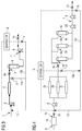
- Fig.1 illustrates a conventional system.
- Pre-treated seawater 1 enters a sulphate removal unit 2 via a sulphate removal booster pump 3.
- a sulphate removal booster pump 3 At the output of the sulphate removal unit 2, one outlet 4 is for salt concentrated seawater, which is dumped, the other outlet 5 is for low sulphate water which is fed to a deaerator 6.
- the treated water 7 passes through a water injection booster pump 8.
- the output of the water injection pump 8 is either sent as injection water 9 to the well, or if there is excess treated water 10, above the well's requirement, this is dumped in the surrounding sea.
- varying the flux for example reducing it to that needed for a reduced injection water requirement, rather than keeping at the design flux of the system, is likely to reduce performance of the treatment system.
- Sulphate removal or reverse osmosis membranes in particular are designed to operate with constant flow, so varying the flow may result in the treated water not being of the required quality, leading to corrosion, or damage to the production equipment.
- the amount of treated injection water required varies, typically reducing from the maximum for which it was designed, but given the treatment system's typically limited flux operating range, a better way of achieving the required turndown is needed. Flexible adjustment to lower the flow requirements, whilst still maintaining performance and quality, is desired.
- One option to reduce the extent of the dumping of treated water is to design the system to have several sub-units of each type of treatment unit, for example sulphate removal, reverse osmosis units, or deaeration units, in parallel, that can be individually stopped.
- An example of this is shown in Fig.2 .
- the components 1 and 3 to 10 are the same and perform the same function as in Fig.1 .
- a parallel arrangement is used, illustrated here, for convenience, as three treatment sub-units 2a, 2b, 2c, although this number can be adapted to the specific requirement.
- Each sub-unit is provided with a valve 11a, 11b, 11c at the entry, which can be switched on or off to control whether or not feed water enters that sub-unit, according to the volume of injection water 9 required for the well.
- a valve 11a, 11b, 11c at the entry, which can be switched on or off to control whether or not feed water enters that sub-unit, according to the volume of injection water 9 required for the well.
- the present invention provides a system and a method of operation designed to reduce the amount of treated water that is dumped, by keeping the treated water in the treatment loop.
- this has the benefit of reducing the amount of energy use and chemical use in the treatment process because less new water has to be fully treated.
- This may also extend the lifetime of the membranes in the treatment unit, as they do not have to process the same amount of untreated seawater as a conventional system, over the same period of operation of the well.
- Treated water having reduced salts and reduced oxygen, relative to the original seawater feed is fed back to join new feed water entering the treatment units, for example the salt reducing membrane units, such as sulphate removal membranes.
- the treated water may be fed back directly after treatment, or may proceed further through the downstream system before being fed back to the feed water inlet to the treatment units.
- flux or flow load on upstream treatment is reduced and so more economical.
- the amount of treatment needed is reduced by feeding the system with already treated fluid.
- FIG. 3 illustrates an example of a fluid treatment system according to the invention.
- Feed fluid 1 from a fluid feed source enters a treatment unit 2, via a feed fluid pump 3.
- the feed fluid may, for example, be seawater, for well injection water.
- the treatment unit may be a salt removal unit, typically for removing sulphate and other salts, or a reverse osmosis unit.
- Treated fluid 5 is typically input to a downstream treatment unit, such as a deaerator 6 before the treated fluid, in this case, deaerated fluid 7, passes through an injection pump 8 and is fed to a well as injection water 9.
- the amount of injection water may be varied by altering the opening of a valve 14 in the injection water line 9. Any excess treated water above the amount required at that time for well injection 9 is returned via line 12b and recirculation line 12 to the inlet of the treatment unit under the control of a controller 13 which opens a valve 15 to allow the appropriate amount to flow through the return line.
- the return line 12b is downstream of the booster pump, if used, or downstream of the injection pump 8.
- the fraction of raw seawater and re-circulated treated water entering the feed water pump 3 may vary, but the controller 13 operates an integrated control loop with system normalization equations for the control valves in the process.
- the treated water may enter a re-circulation loop at an earlier stage in the cycle, for example via line 12a, directly after the treatment unit 2, or some treated water may be re-circulated at each stage, according to the requirement and in response to control signals from controller.
- the treated fluid 12 at the input to the treatment units 2 is the combination of treated fluid from both recirculation lines 12a, 12b, if both are provided.
- Feed fluid 1a may be pre-treated in feed fluid pre-treatment units 18 and the pre-treated feed fluid 1b passes through fluid pump 3 and enters fluid treatment sub-units 2a, 2b, 2c, arranged in parallel. All of the treated fluid may pass through valve 16 to supply each of the downstream units, for example, deaerator units 6a, 6b, 6c at inlets 5a, 5b, 5c, or the controller may adjust the valve opening of valves 16, 17, so that some treated fluid is re-circulated at this stage via line 12a.
- Fluid from the downstream units may pass through an optional booster pump 20 to increase the pressure for an input 7 to fluid injection pump 8 and again the controller determines the extent of opening of valves 14, 15 so that the amount of treated fluid to meet the requirement of the specified point in a production process, in this example injection water to meet the requirement of the well, is provided and any excess is recirculated via line 12b.
- Recirculated fluid 12 from lines 12a, 12b is combined and input to the feed fluid pump 3.
- the controller 13 controls the amount of recirculated fluid 12 entering, so that the flux into the fluid treatment unit remains substantially constant.
- the feed fluid is topped up to keep a constant system flow, under the control of a system controller (not shown). Valve 19 is controlled accordingly.
- the feed fluid 1 is typically seawater
- the fluid treatment units 2 are typically sulphate removal units, or reverse osmosis units and the downstream treatment units 6 are typically deaeration units, for example membrane deaerators.
- the treatment units may be reverse osmosis units and the downstream units may be chemical polishing units.
- treated fluid recirculation makes a more flexible injection rate possible without dumping of treated fluid, while maintaining a substantially constant flux for the treatment units.
- the size of the treatment units 2, such as salt reducing membrane units, may be optimized with respect to flow and footprint.
- the downstream units 6, such as deaeration units or chemical polishing units, or the treatment units, such as salt removal units, or reverse osmosis units, may be constructed as parallel sub-units, so increasing the flexibility of the overall system.
- Feed fluid consumption, as well as wear and tear on the upstream system, is reduced when operating one or more of the recirculation loops 12a, 12b. This reduces operational and maintenance costs. Other beneficial effects are that the recirculation of treated fluid gives rise to better performance in the treatment units and downstream units for the treated fluid and that the load on the pre-treatment system 18 for the feed fluid before the fluid is fed into the treatment units, also reduces cost and maintenance.
- Fig.5 is a flow diagram showing the operation steps for the water treatment system of Figs.3 and 4 .
- the controller determines 30 the requirement for injection water at the well.
- Feed water 1 is received 31 at an inlet to a fluid treatment unit 2 and the fluid is treated, then output.
- the feed water may have had one or more pre-treatment steps applied in pre-treatment units (not shown), for example chemical treatment.
- the fluid treatment unit may comprise a single unit, or parallel banks of treatment sub-units.
- the controller determines 33 whether re-circulation of the treated water is required at this stage, for example if the flux requirement at the inlet to the well is below the design flux at the outlet of the treatment unit, there is a need to recirculate some of the treated fluid and the controller determines whether some of this recirculation should take place directly after the treatment units. If not 34, then all the treated water is supplied 35 to downstream processing units 6.
- the downstream processing unit may be a single unit, or a parallel bank of downstream processing sub-units. If re-circulation is required 36 at this stage, then the controller sends a signal to cause a valve 17 in line 12a to open sufficiently to take off the necessary proportion of the treated fluid 5 and that fluid is re-circulated 37 to the feed water inlet/feed pump 3. The remainder is fed to the downstream units 6 and processed 38.
- the process of sensing and determining the well injection water requirement and adapting the amount of recirculation at one or both stages 12a, 12b continues, either at regular intervals, or in response to a detected change in sensed data exceeding a threshold.
- a further mechanism (not shown) for very fine control of the amount of well injection water produced without altering the flux into the treatment unit is to allow small amounts of treated water to be dumped, either after the treatment unit, or after deaearation, for example, up to 5% of the generated capacity. This still improves the water quality of the water surrounding the platform, by significantly reducing the amount of dumping compared to the conventional dumping practice, but allows more precise control of the amount of injection water fed to the well.
Priority Applications (1)
| Application Number | Priority Date | Filing Date | Title |
|---|---|---|---|
| EP16176177.0A EP3260424A1 (fr) | 2016-06-24 | 2016-06-24 | Système et procédé de traitement de fluide |
Applications Claiming Priority (1)
| Application Number | Priority Date | Filing Date | Title |
|---|---|---|---|
| EP16176177.0A EP3260424A1 (fr) | 2016-06-24 | 2016-06-24 | Système et procédé de traitement de fluide |
Publications (1)
| Publication Number | Publication Date |
|---|---|
| EP3260424A1 true EP3260424A1 (fr) | 2017-12-27 |
Family
ID=56360179
Family Applications (1)
| Application Number | Title | Priority Date | Filing Date |
|---|---|---|---|
| EP16176177.0A Withdrawn EP3260424A1 (fr) | 2016-06-24 | 2016-06-24 | Système et procédé de traitement de fluide |
Country Status (1)
| Country | Link |
|---|---|
| EP (1) | EP3260424A1 (fr) |
Cited By (1)
| Publication number | Priority date | Publication date | Assignee | Title |
|---|---|---|---|---|
| RU193152U1 (ru) * | 2019-06-17 | 2019-10-15 | федеральное государственное бюджетное образовательное учреждение высшего образования "Ульяновский государственный технический университет" | Водоподготовительная установка подпиточной воды тепловой электрической станции |
Citations (7)
| Publication number | Priority date | Publication date | Assignee | Title |
|---|---|---|---|---|
| DE19748997A1 (de) * | 1997-11-06 | 1999-05-20 | Schilling Chemie Gmbh U Produk | Umkehrosmoseanlage und Verfahren zum Betrieb einer Umkehrosmoseanlage |
| US20040079700A1 (en) * | 2002-10-23 | 2004-04-29 | Jonathan Wood | Production of water for injection using reverse osmosis |
| US20070295650A1 (en) * | 2006-06-21 | 2007-12-27 | Miura Co., Ltd. | Membrane filtration system |
| US20080308475A1 (en) * | 2007-06-15 | 2008-12-18 | Mitsubishi Heavy Industries, Ltd. | Demineralizer |
| WO2011051666A1 (fr) * | 2009-10-27 | 2011-05-05 | Vws Westgarth Limited | Appareil et procédé de traitement de fluide |
| WO2013012548A1 (fr) * | 2011-07-20 | 2013-01-24 | Cameron International Corporation | Système de distribution d'eau à salinité régulée pour récupération de pétrole améliorée |
| EP2959964A1 (fr) * | 2013-02-20 | 2015-12-30 | Mitsubishi Heavy Industries, Ltd. | Procédé de fonctionnement de dispositif de membrane d'osmose inverse |
-
2016
- 2016-06-24 EP EP16176177.0A patent/EP3260424A1/fr not_active Withdrawn
Patent Citations (7)
| Publication number | Priority date | Publication date | Assignee | Title |
|---|---|---|---|---|
| DE19748997A1 (de) * | 1997-11-06 | 1999-05-20 | Schilling Chemie Gmbh U Produk | Umkehrosmoseanlage und Verfahren zum Betrieb einer Umkehrosmoseanlage |
| US20040079700A1 (en) * | 2002-10-23 | 2004-04-29 | Jonathan Wood | Production of water for injection using reverse osmosis |
| US20070295650A1 (en) * | 2006-06-21 | 2007-12-27 | Miura Co., Ltd. | Membrane filtration system |
| US20080308475A1 (en) * | 2007-06-15 | 2008-12-18 | Mitsubishi Heavy Industries, Ltd. | Demineralizer |
| WO2011051666A1 (fr) * | 2009-10-27 | 2011-05-05 | Vws Westgarth Limited | Appareil et procédé de traitement de fluide |
| WO2013012548A1 (fr) * | 2011-07-20 | 2013-01-24 | Cameron International Corporation | Système de distribution d'eau à salinité régulée pour récupération de pétrole améliorée |
| EP2959964A1 (fr) * | 2013-02-20 | 2015-12-30 | Mitsubishi Heavy Industries, Ltd. | Procédé de fonctionnement de dispositif de membrane d'osmose inverse |
Cited By (1)
| Publication number | Priority date | Publication date | Assignee | Title |
|---|---|---|---|---|
| RU193152U1 (ru) * | 2019-06-17 | 2019-10-15 | федеральное государственное бюджетное образовательное учреждение высшего образования "Ульяновский государственный технический университет" | Водоподготовительная установка подпиточной воды тепловой электрической станции |
Similar Documents
| Publication | Publication Date | Title |
|---|---|---|
| RU2718079C1 (ru) | Устройство и способ обработки воды посредством обратного осмоса или нанофильтрации | |
| US9932250B2 (en) | Membrane filtration system | |
| AU2019332755B2 (en) | High recovery variable volume reverse osmosis membrane system | |
| US20140311980A1 (en) | System to Provide a Supply of Controlled Salinity Water for Enhanced Oil Recovery | |
| US20090152197A1 (en) | System for Energy Recovery and Reduction of Deposits on the Membrane Surfaces in (Variable Power and Variable Production) Reverse Osmosis Desalination Systems | |
| US10435306B2 (en) | Water treatment system and method | |
| AU3167100A (en) | Method and device for desalting water | |
| KR20170140920A (ko) | 에너지 절약을 위한 역삼투 멤브레인 장치 및 이를 이용한 수처리 방법 | |
| EP3260424A1 (fr) | Système et procédé de traitement de fluide | |
| US20170334747A1 (en) | System and method for flexible low-energy membrane-based liquid purification | |
| CN115461133B (zh) | 液体处理装置、纯水制造系统以及液体处理方法 | |
| US10434472B2 (en) | Water treatment system | |
| WO2018047156A1 (fr) | Procédé et système de traitement de liquide | |
| US11878270B2 (en) | Osmosis modules having recirculation loops | |
| CN210313834U (zh) | 一种处理高硬度岸供淡水船用反渗透造水机 | |
| KR101647393B1 (ko) | 유량 제어 청수 공급 시스템 | |
| JP6011748B1 (ja) | バラスト水処理装置及びバラスト水処理方法 | |
| WO2020217372A1 (fr) | Système de traitement d'eaux de ballast et navire le comprenant | |
| WO2017033487A1 (fr) | Dispositif et procédé de traitement des eaux de ballast | |
| CN113396130A (zh) | 水处理系统以及水处理方法 | |
| CN114340767A (zh) | 用于控制水净化的方法及水净化装置 | |
| KR20170047708A (ko) | 해수 담수화 및 폐수 처리를 위한 장치와 방법 | |
| JP2019136639A (ja) | 水処理装置 |
Legal Events
| Date | Code | Title | Description |
|---|---|---|---|
| PUAI | Public reference made under article 153(3) epc to a published international application that has entered the european phase |
Free format text: ORIGINAL CODE: 0009012 |
|
| STAA | Information on the status of an ep patent application or granted ep patent |
Free format text: STATUS: THE APPLICATION HAS BEEN PUBLISHED |
|
| AK | Designated contracting states |
Kind code of ref document: A1 Designated state(s): AL AT BE BG CH CY CZ DE DK EE ES FI FR GB GR HR HU IE IS IT LI LT LU LV MC MK MT NL NO PL PT RO RS SE SI SK SM TR |
|
| AX | Request for extension of the european patent |
Extension state: BA ME |
|
| STAA | Information on the status of an ep patent application or granted ep patent |
Free format text: STATUS: THE APPLICATION IS DEEMED TO BE WITHDRAWN |
|
| 18D | Application deemed to be withdrawn |
Effective date: 20180628 |