EP3260331A1 - Information processing device - Google Patents
Information processing device Download PDFInfo
- Publication number
- EP3260331A1 EP3260331A1 EP16752264.8A EP16752264A EP3260331A1 EP 3260331 A1 EP3260331 A1 EP 3260331A1 EP 16752264 A EP16752264 A EP 16752264A EP 3260331 A1 EP3260331 A1 EP 3260331A1
- Authority
- EP
- European Patent Office
- Prior art keywords
- user
- control
- hand
- control unit
- unit
- Prior art date
- Legal status (The legal status is an assumption and is not a legal conclusion. Google has not performed a legal analysis and makes no representation as to the accuracy of the status listed.)
- Withdrawn
Links
Images


Classifications
-
- G—PHYSICS
- G06—COMPUTING OR CALCULATING; COUNTING
- G06F—ELECTRIC DIGITAL DATA PROCESSING
- G06F3/00—Input arrangements for transferring data to be processed into a form capable of being handled by the computer; Output arrangements for transferring data from processing unit to output unit, e.g. interface arrangements
- G06F3/01—Input arrangements or combined input and output arrangements for interaction between user and computer
- G06F3/017—Gesture based interaction, e.g. based on a set of recognized hand gestures
-
- B—PERFORMING OPERATIONS; TRANSPORTING
- B60—VEHICLES IN GENERAL
- B60K—ARRANGEMENT OR MOUNTING OF PROPULSION UNITS OR OF TRANSMISSIONS IN VEHICLES; ARRANGEMENT OR MOUNTING OF PLURAL DIVERSE PRIME-MOVERS IN VEHICLES; AUXILIARY DRIVES FOR VEHICLES; INSTRUMENTATION OR DASHBOARDS FOR VEHICLES; ARRANGEMENTS IN CONNECTION WITH COOLING, AIR INTAKE, GAS EXHAUST OR FUEL SUPPLY OF PROPULSION UNITS IN VEHICLES
- B60K35/00—Instruments specially adapted for vehicles; Arrangement of instruments in or on vehicles
- B60K35/10—Input arrangements, i.e. from user to vehicle, associated with vehicle functions or specially adapted therefor
-
- B—PERFORMING OPERATIONS; TRANSPORTING
- B60—VEHICLES IN GENERAL
- B60K—ARRANGEMENT OR MOUNTING OF PROPULSION UNITS OR OF TRANSMISSIONS IN VEHICLES; ARRANGEMENT OR MOUNTING OF PLURAL DIVERSE PRIME-MOVERS IN VEHICLES; AUXILIARY DRIVES FOR VEHICLES; INSTRUMENTATION OR DASHBOARDS FOR VEHICLES; ARRANGEMENTS IN CONNECTION WITH COOLING, AIR INTAKE, GAS EXHAUST OR FUEL SUPPLY OF PROPULSION UNITS IN VEHICLES
- B60K35/00—Instruments specially adapted for vehicles; Arrangement of instruments in or on vehicles
- B60K35/20—Output arrangements, i.e. from vehicle to user, associated with vehicle functions or specially adapted therefor
- B60K35/21—Output arrangements, i.e. from vehicle to user, associated with vehicle functions or specially adapted therefor using visual output, e.g. blinking lights or matrix displays
- B60K35/22—Display screens
-
- B—PERFORMING OPERATIONS; TRANSPORTING
- B60—VEHICLES IN GENERAL
- B60R—VEHICLES, VEHICLE FITTINGS, OR VEHICLE PARTS, NOT OTHERWISE PROVIDED FOR
- B60R16/00—Electric or fluid circuits specially adapted for vehicles and not otherwise provided for; Arrangement of elements of electric or fluid circuits specially adapted for vehicles and not otherwise provided for
- B60R16/02—Electric or fluid circuits specially adapted for vehicles and not otherwise provided for; Arrangement of elements of electric or fluid circuits specially adapted for vehicles and not otherwise provided for electric constitutive elements
-
- G—PHYSICS
- G02—OPTICS
- G02B—OPTICAL ELEMENTS, SYSTEMS OR APPARATUS
- G02B27/00—Optical systems or apparatus not provided for by any of the groups G02B1/00 - G02B26/00, G02B30/00
- G02B27/01—Head-up displays
- G02B27/0101—Head-up displays characterised by optical features
-
- G—PHYSICS
- G06—COMPUTING OR CALCULATING; COUNTING
- G06F—ELECTRIC DIGITAL DATA PROCESSING
- G06F3/00—Input arrangements for transferring data to be processed into a form capable of being handled by the computer; Output arrangements for transferring data from processing unit to output unit, e.g. interface arrangements
- G06F3/01—Input arrangements or combined input and output arrangements for interaction between user and computer
- G06F3/016—Input arrangements with force or tactile feedback as computer generated output to the user
-
- G—PHYSICS
- G06—COMPUTING OR CALCULATING; COUNTING
- G06F—ELECTRIC DIGITAL DATA PROCESSING
- G06F3/00—Input arrangements for transferring data to be processed into a form capable of being handled by the computer; Output arrangements for transferring data from processing unit to output unit, e.g. interface arrangements
- G06F3/01—Input arrangements or combined input and output arrangements for interaction between user and computer
- G06F3/048—Interaction techniques based on graphical user interfaces [GUI]
- G06F3/0487—Interaction techniques based on graphical user interfaces [GUI] using specific features provided by the input device, e.g. functions controlled by the rotation of a mouse with dual sensing arrangements, or of the nature of the input device, e.g. tap gestures based on pressure sensed by a digitiser
- G06F3/0488—Interaction techniques based on graphical user interfaces [GUI] using specific features provided by the input device, e.g. functions controlled by the rotation of a mouse with dual sensing arrangements, or of the nature of the input device, e.g. tap gestures based on pressure sensed by a digitiser using a touch-screen or digitiser, e.g. input of commands through traced gestures
-
- G—PHYSICS
- G06—COMPUTING OR CALCULATING; COUNTING
- G06F—ELECTRIC DIGITAL DATA PROCESSING
- G06F3/00—Input arrangements for transferring data to be processed into a form capable of being handled by the computer; Output arrangements for transferring data from processing unit to output unit, e.g. interface arrangements
- G06F3/16—Sound input; Sound output
- G06F3/167—Audio in a user interface, e.g. using voice commands for navigating, audio feedback
-
- G—PHYSICS
- G06—COMPUTING OR CALCULATING; COUNTING
- G06V—IMAGE OR VIDEO RECOGNITION OR UNDERSTANDING
- G06V40/00—Recognition of biometric, human-related or animal-related patterns in image or video data
- G06V40/10—Human or animal bodies, e.g. vehicle occupants or pedestrians; Body parts, e.g. hands
- G06V40/107—Static hand or arm
- G06V40/113—Recognition of static hand signs
-
- G—PHYSICS
- G06—COMPUTING OR CALCULATING; COUNTING
- G06V—IMAGE OR VIDEO RECOGNITION OR UNDERSTANDING
- G06V40/00—Recognition of biometric, human-related or animal-related patterns in image or video data
- G06V40/20—Movements or behaviour, e.g. gesture recognition
- G06V40/28—Recognition of hand or arm movements, e.g. recognition of deaf sign language
-
- B—PERFORMING OPERATIONS; TRANSPORTING
- B60—VEHICLES IN GENERAL
- B60K—ARRANGEMENT OR MOUNTING OF PROPULSION UNITS OR OF TRANSMISSIONS IN VEHICLES; ARRANGEMENT OR MOUNTING OF PLURAL DIVERSE PRIME-MOVERS IN VEHICLES; AUXILIARY DRIVES FOR VEHICLES; INSTRUMENTATION OR DASHBOARDS FOR VEHICLES; ARRANGEMENTS IN CONNECTION WITH COOLING, AIR INTAKE, GAS EXHAUST OR FUEL SUPPLY OF PROPULSION UNITS IN VEHICLES
- B60K2360/00—Indexing scheme associated with groups B60K35/00 or B60K37/00 relating to details of instruments or dashboards
- B60K2360/11—Instrument graphical user interfaces or menu aspects
- B60K2360/111—Instrument graphical user interfaces or menu aspects for controlling multiple devices
-
- B—PERFORMING OPERATIONS; TRANSPORTING
- B60—VEHICLES IN GENERAL
- B60K—ARRANGEMENT OR MOUNTING OF PROPULSION UNITS OR OF TRANSMISSIONS IN VEHICLES; ARRANGEMENT OR MOUNTING OF PLURAL DIVERSE PRIME-MOVERS IN VEHICLES; AUXILIARY DRIVES FOR VEHICLES; INSTRUMENTATION OR DASHBOARDS FOR VEHICLES; ARRANGEMENTS IN CONNECTION WITH COOLING, AIR INTAKE, GAS EXHAUST OR FUEL SUPPLY OF PROPULSION UNITS IN VEHICLES
- B60K2360/00—Indexing scheme associated with groups B60K35/00 or B60K37/00 relating to details of instruments or dashboards
- B60K2360/11—Instrument graphical user interfaces or menu aspects
- B60K2360/115—Selection of menu items
-
- B—PERFORMING OPERATIONS; TRANSPORTING
- B60—VEHICLES IN GENERAL
- B60K—ARRANGEMENT OR MOUNTING OF PROPULSION UNITS OR OF TRANSMISSIONS IN VEHICLES; ARRANGEMENT OR MOUNTING OF PLURAL DIVERSE PRIME-MOVERS IN VEHICLES; AUXILIARY DRIVES FOR VEHICLES; INSTRUMENTATION OR DASHBOARDS FOR VEHICLES; ARRANGEMENTS IN CONNECTION WITH COOLING, AIR INTAKE, GAS EXHAUST OR FUEL SUPPLY OF PROPULSION UNITS IN VEHICLES
- B60K2360/00—Indexing scheme associated with groups B60K35/00 or B60K37/00 relating to details of instruments or dashboards
- B60K2360/146—Instrument input by gesture
- B60K2360/1464—3D-gesture
-
- B—PERFORMING OPERATIONS; TRANSPORTING
- B60—VEHICLES IN GENERAL
- B60K—ARRANGEMENT OR MOUNTING OF PROPULSION UNITS OR OF TRANSMISSIONS IN VEHICLES; ARRANGEMENT OR MOUNTING OF PLURAL DIVERSE PRIME-MOVERS IN VEHICLES; AUXILIARY DRIVES FOR VEHICLES; INSTRUMENTATION OR DASHBOARDS FOR VEHICLES; ARRANGEMENTS IN CONNECTION WITH COOLING, AIR INTAKE, GAS EXHAUST OR FUEL SUPPLY OF PROPULSION UNITS IN VEHICLES
- B60K35/00—Instruments specially adapted for vehicles; Arrangement of instruments in or on vehicles
- B60K35/20—Output arrangements, i.e. from vehicle to user, associated with vehicle functions or specially adapted therefor
- B60K35/21—Output arrangements, i.e. from vehicle to user, associated with vehicle functions or specially adapted therefor using visual output, e.g. blinking lights or matrix displays
- B60K35/23—Head-up displays [HUD]
-
- B—PERFORMING OPERATIONS; TRANSPORTING
- B60—VEHICLES IN GENERAL
- B60K—ARRANGEMENT OR MOUNTING OF PROPULSION UNITS OR OF TRANSMISSIONS IN VEHICLES; ARRANGEMENT OR MOUNTING OF PLURAL DIVERSE PRIME-MOVERS IN VEHICLES; AUXILIARY DRIVES FOR VEHICLES; INSTRUMENTATION OR DASHBOARDS FOR VEHICLES; ARRANGEMENTS IN CONNECTION WITH COOLING, AIR INTAKE, GAS EXHAUST OR FUEL SUPPLY OF PROPULSION UNITS IN VEHICLES
- B60K35/00—Instruments specially adapted for vehicles; Arrangement of instruments in or on vehicles
- B60K35/20—Output arrangements, i.e. from vehicle to user, associated with vehicle functions or specially adapted therefor
- B60K35/26—Output arrangements, i.e. from vehicle to user, associated with vehicle functions or specially adapted therefor using acoustic output
-
- G—PHYSICS
- G02—OPTICS
- G02B—OPTICAL ELEMENTS, SYSTEMS OR APPARATUS
- G02B27/00—Optical systems or apparatus not provided for by any of the groups G02B1/00 - G02B26/00, G02B30/00
- G02B27/01—Head-up displays
- G02B27/0101—Head-up displays characterised by optical features
- G02B2027/0138—Head-up displays characterised by optical features comprising image capture systems, e.g. camera
-
- G—PHYSICS
- G06—COMPUTING OR CALCULATING; COUNTING
- G06F—ELECTRIC DIGITAL DATA PROCESSING
- G06F2203/00—Indexing scheme relating to G06F3/00 - G06F3/048
- G06F2203/038—Indexing scheme relating to G06F3/038
- G06F2203/0381—Multimodal input, i.e. interface arrangements enabling the user to issue commands by simultaneous use of input devices of different nature, e.g. voice plus gesture on digitizer
Definitions
- the present invention relates to an information processing device.
- PTL 1 describes a control device of in-vehicle equipment which superimposes and displays, on a head up display (HUD), the control menu of the in-vehicle equipment and the projected image of the driver's hand placed on the control unit, and thereby allows the driver to control the control unit while viewing the projected image to simplify and facilitate the selection control of the in-vehicle equipment so that such control will not interfere with the driving of the vehicle.
- HUD head up display
- an in-vehicle device comprises: a gesture detection unit which recognizes a position of a user's hand located within a predetermined range; an output information control unit which controls output information to be output to a display unit; and an in-vehicle device control unit which receives an input from a control unit equipped in a vehicle and thereby controls the in-vehicle device, wherein: when the gesture detection unit detects that the user's hand has been placed at a predetermined position for a given length of time, the output information control unit triggers the display unit to display candidates of an operation to be executed by the in-vehicle device control unit by associating the candidates with motions of the user's hand; and when the gesture detection unit detects that the user's hand has been placed at the predetermined position for a given length of time and the user's hand has thereafter been moved from the predetermined position, the output information control unit changes a selection method or a control guide of the operation to be executed by the in-vehicle device control
- the present invention it is possible to improve the safety and controllability of the control of in-vehicle equipment by a driver who is driving a vehicle.
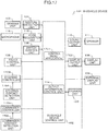
- Fig. 1 is a configuration diagram of an in-vehicle device 101 in this embodiment.
- An in-vehicle device control unit 102 is the part that controls the overall operation of the in-vehicle device 101, and realizes the functions as a messenger application 113 and an output information control unit 114 by performing operations according to programs related to the messenger application 113 and the output information control unit 114 stored in a storage unit (not shown).
- the in-vehicle device 101 may also be loaded with applications other than the messenger application 113 and the output information control unit 114, and these programs may also be stored in a storage unit at the time of factory shipment, or may be stored in the storage unit through the user's selection via a communication unit 107, or via an externally connected IF (not shown) such as a USB terminal.
- the in-vehicle device control unit 102 controls the basic operation as a car navigation system, and additionally controls the contents to be output based on the various types of input information.
- a sensing unit 103 is the part that detects the distance between the user's hand and a sensor, and detects the waving (or moving) of the user's hand, and is configured, for example, from a sensor such as an infrared distance sensor, a laser distance sensor, an ultrasonic distance sensor, a distance image sensor, an electrolytic sensor, or an image sensor, a microcomputer which performs data processing, and software that runs on the microcomputer.
- a sensor such as an infrared distance sensor, a laser distance sensor, an ultrasonic distance sensor, a distance image sensor, an electrolytic sensor, or an image sensor
- a microcomputer which performs data processing, and software that runs on the microcomputer.
- the sensors to be used in the sensing unit 103 and any sensor may be used so as long as it has a function of being able to obtain a signal for detecting the distance to the user's hand and detecting the waving of the user's hand.
- a gesture detection unit 104 Based on the sensor data obtained from the sensing unit 103, a gesture detection unit 104 detects whether the user placed one's hand at a certain position, and whether a predetermined gesture (for instance, hand waving motion in a vertical/horizontal direction) was performed. For example, the user's hand placement is detected by analyzing whether a predetermined sensor value has continued for a given length of time, and the gesture operation is detected by analyzing the difference between the response times of the hand detection results between a plurality of sensors.
- a predetermined gesture for instance, hand waving motion in a vertical/horizontal direction
- a switch control unit 105 is a hardware switch for controlling the in-vehicle device, and may be a button-pressing type, or a jog-dial type.
- a touch control unit 106 sends the touched coordinates to the in-vehicle device control unit 102, and controls the in-vehicle device.
- a microphone 115 acquires sounds within the vehicle.
- a voice recognition unit 116 converts the speech from the input sound data into a text code string.
- a communication unit 107 is connected to an outside network, and inputs/outputs various types of information. For example, the communication unit 107 inputs navigation-related information and sends/receives messages.
- An external switch control unit 117 is a switch control unit installed at a location that is different from the location of the in-vehicle device 101, and considered may be a steering switch mounted near the steering wheel, or a commander switch mounted on the center console of the vehicle.
- a display unit 108 is a device for presenting video information to the user, and, for instance, is a device comprising a display device such as an LCD (Liquid Crystal Display), and an arithmetic processing device and a memory which are required for the display processing of video contents and GUI (Graphical User Interface).
- a display device such as an LCD (Liquid Crystal Display)
- arithmetic processing device and a memory which are required for the display processing of video contents and GUI (Graphical User Interface).
- An external display unit 109 is a display that is installed at a location within the vehicle which is different from the location of the in-vehicle device 101 and displays videos.
- the external display unit 109 may be a head up display (HUD) mounted at the anterior of the driver's seat.
- An HUD can display various types of information while allowing the scenery ahead of the driver (user) to pass therethrough.
- a sound output unit 110 is the part that outputs sounds or voices.
- a speaker 111 outputs sound from the sound output unit 110.
- a tactile IF output unit 112 is the part that conveys some type of tactile information to the user, and, for instance, is configured from an ultrasonic array formed from a plurality of ultrasonic elements, and conveys the spatial pressure of an arbitrary distance of the device. Otherwise, an air blower may be provided to yield the same effect. Moreover, the tactile IF output unit 112 may also be configured from an oscillator mounted near the steering wheel to cause the entire steering wheel to vibrate, and there is no particular limitation regarding the constituent elements.
- a messenger application 113 sends and receives messages to and from the communication unit 107, stores the input messages, and outputs such messages. Moreover, when sending a message, the messenger application 113 sends the outbound message to the communication unit 107.
- An output information control unit 114 controls the contents to be output to the display unit 108 or the external display unit 109.
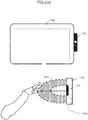
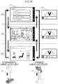
- Fig. 2(a) shows an installation example of the sensing unit 103.
- the sensing unit 103 is mounted on the driver's side in a right-side steering wheel vehicle relative to the display unit 108, and can detect the distance information of an object from the spot of the sensor element, and the movement of the object. Consequently, as shown in the lower diagram of Fig. 2(a) , the space between the in-vehicle device 101 and the user is divided into a plurality of areas, and in which area the user's hand exists can be detected in detail. As shown in the lower diagram, the space is divided into an area 201 that is close to the sensor position, and an area 202 that is even closer to the sensor position. Note that the number of sensor elements, installation position, and areas to be detected are not limited to this example.
- the messenger application 113 when the messenger application 113 is to output videos or voices to output units such as the display unit 108, the external display unit 109, and the speaker 111, the messenger application 113 sends video or voice information to the output information control unit 114, and the output information control unit 114 determines whether or not to output the received information to the foregoing output units.
- the messenger application 113 outputs videos to the display unit 108
- the messenger application 113 outputs voices will be used.
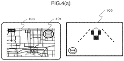
- the output information control unit 114 displays a navigation screen and an icon 401 of the messenger application 113 on the display unit 108 (center display in this example) as shown in Fig. 4(a) when the operation is started.
- the messenger application 113 is executed in the background by the in-vehicle device control unit 102 together with the activation of the in-vehicle device 101, and is activated by the output information control unit 114 when the touch control unit 106 detects a touch control of touching the icon 401, or the gesture detection unit 104 detects the user's prescribed gesture operation (for instance, hand waving in the leftward direction in front of the sensor).
- the output information control unit 114 displays a navigation screen and a screen related to the messenger application 113 on the external display unit 109 (HUD in this example) when the operation is started.
- the messenger application 113 When a message is received from the outside via the communication unit 107 (S301), the messenger application 113 outputs a sound effect to notify an incoming message, displays the total number of received messages on the external display unit 109 as shown with an icon 402 of Fig. 4(b) , and notifies the user that the number of unread messages has increased.
- the output information control unit 114 switches the display to a screen for using the application by activating the messenger application 113 as shown in Fig. 4(c) (S304).
- the messenger application 113 thereafter outputs voice information which reads the received messages in order from the oldest message (S305).
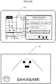
- Fig. 4(c) is a display example when using the half screen of the display unit 108 as the screen of the messenger application 113.
- the messenger application 113 When the touch control unit 106 detects that the user touched an area of an icon 403 on Fig. 4(c) , the messenger application 113 causes the display unit 108 to display a screen for performing the respective controls of stamp reply, fixed phrase reply, free speech reply, and message return/forward from the left side of the area of the icon 403. Moreover, while the voice information is being output in S305, the messenger application 113 causes the external display unit 109 to display the current number of unread messages as with an icon 404 in the lower diagram of Fig. 4(c) , and the name of the sender of the message that is being read.
- the messenger application 113 causes the speaker 111 to output voice information so that the latest message among the unread messages is read (S308).
- the messenger application 113 When no such gesture operation is detected, the messenger application 113 continues to output the voice information so that the unread messages are read in order from the oldest message (S307), and, when the reading of the latest message is finished, enters a reply control standby state while causing the display unit 108 and the external display unit 109 to continue displaying the last sender as shown in Fig. 4(d) (S309).
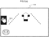
- the messenger application 113 displays an icon 501, which indicates that a gesture-based reply control can be performed, on the external display unit 109 as shown in Fig. 5(a) .
- the messenger application 113 outputs a sound effect to notify the user that the hand placement position is erroneous.
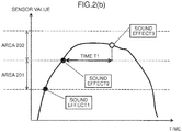
- Fig. 2(b) and Fig. 2(c) are diagrams showing in detail the relation of the detection state of the user's hand and the output of sound effects.
- Fig. 2(b) and Fig. 2(c) respectively represent the time axis and the sensor value of the sensing unit 103, and show the boundary for determining whether the sensor value falls within the area 201 or the area 202.
- Fig. 2(b) shows an example where the user stretches one's hand toward the area 202, and places one's hand in the area 202 for a given length of time.
- the gesture detection unit 104 detects that the user's hand entered the area 201
- the gesture detection unit 104 outputs a sound effect 1.
- the gesture detection unit 104 detects that the user's hand entered the area 202
- the gesture detection unit 104 outputs a sound effect 2.
- the gesture detection unit 104 continues to detect that the user's hand is in the area 202 for a time T1 or longer (for instance, for 0.5 seconds or longer)
- the gesture detection unit 104 outputs a sound effect 3, and switches the screen of the external display unit 109 as explained with reference to S311.
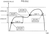
- Fig. 2(c) shows an example where the user continues to place one's hand in the area 201.
- the gesture detection unit 104 outputs the sound effect 1 upon detecting that the user's hand entered the area 201, and outputs a sound effect 4 upon detecting that the user's hand is in the area 201 for a time T2 or longer (for instance, for 0.3 seconds or longer). If the user's hand is subsequently detected in the area 202, the same process as the example of Fig. 2(b) is performed.
- the control of placing one's hand in the area 202 for the time T1 or longer is sometimes simply referred to as "hand placement".
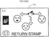
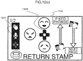
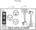
- Fig. 5(c) shows an example of a case where a control menu, which enables the user to perform a stamp reply, is displayed.
- the icon 502 is a control guide which means that, when the user performs a gesture in the upward, leftward or downward direction while placing one's hand over the icon 502, the corresponding stamp can be selected.
- the display of 1/2 at the upper left corner refers to the total number of pages of the displayed stamp candidates, and the current page.
- the displayed contents of the external display unit 109 are switched to the displayed contents shown in Fig. 5(d) (S315).
- the icon 503 represents the stamp candidates that can currently be selected.
- the icon 504 represents that the corresponding control will be performed when the gesture control corresponding to the displayed direction (upward hand waving or downward hand waving) is performed.
- the display of "fixed phrase” means switching the reply method to a fixed phrase reply
- the display of "next page” means switching the stamp candidates from those displayed with the icon 503 to the next candidate group.
- the messenger application 113 erases the control guide from the screen of the external display unit 109, and makes a transition to the reply control standby state of S309 (S320).
- the messenger application 113 displays the contents of the reply control result (selected stamp in this example) on the display unit 108, displays the name of the user who sent the reply on the external display unit 109, and reads the reply message.
- this operation flow is an explanation of a representative example of the operation of the in-vehicle device 101 of the present invention, and the operation, display, and sound effect are not limited to this example.
- the present invention is not limited thereto, and can be applied to the overall control of the in-vehicle device control unit 102 of selecting a plurality of options.
- Fig. 3(b) shows a simplified version of the operation flow. The basic operation is as explained above, and, while the explanation of the operation in each step is the same as those with the same step number of Fig. 3(a) , S316 of Fig. 3(b) does not have to be limited to vertical hand waving, and may also accept various controls, such as the control using a steering switch.
- the configuration may also be such that the message is read at the same time that the message is received, or the contents of the received message may be displayed on the external display unit 109. Consequently, it will be easier for the user to comprehend the message.
- the configuration may also be such that at the reply control standby it can be accepted at any time without waiting for the reading of the latest message to be finished. Consequently, the user may send a reply at any time.
- the configuration may be such that the tactile sensation is presented in mid air in such area by the tactile IF unit 112.
- the configuration may be such that the pressure points of an ultrasonic device array appear on the boundary of the areas, or a tactile sensation is given on the vertical line of the area using an air blower. Consequently, the user can place one's hand in the area while looking straight ahead, and can send a reply safely even though such control is performed while driving.
- the configuration may also be such that the transition is made to the reply method selection state (stamp, fixed phrase, free speech or the like) before the foregoing transition. Consequently, the user can select one's preferred reply method at the time that the reply control is started.
- the user's gesture is accepted after the user's hand placement is detected and the control guide is displayed on the external display unit 109 in this example
- the user's gesture may also be accepted from a given length of time before (for instance, 0.2 seconds before) displaying the control guide. Consequently, once the user becomes familiar with the control and learns which gesture corresponds to which control, the control can be performed without having to display unnecessary screens on the external display unit 109, and the control time can also be shortened.
- the configuration may also be such that the process proceeds to S320 upon detecting a predetermined control (for instance, hand waving motion in the left direction, switch control, or the like) prior to satisfying the foregoing condition. Consequently, the user can switch the display of the external display unit 109 to a navigation screen at one's desired timing.
- a predetermined control for instance, hand waving motion in the left direction, switch control, or the like
- control guide displayed on the external display unit 109 and the gesture direction are not limited to 3 directions, and arbitrary directions and number of directions may be used.
- directions in which the gesture control can be easily performed while sitting in the driver's seat may be set. For example, if the user's gesture is made in the direction of the steering wheel, the user's hand may hit the steering wheel while driving the vehicle and, therefore, a gesture in such direction is excluded as an option.
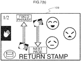
- the configuration may be such that whether the steering wheel of the vehicle to be driven is a right-side steering wheel or a left-side steering wheel can be set in advance using the setting screen and, when the steering wheel is a left-side steering wheel, the control guide displayed on the external display unit 109 indicates the 3 directions of upward, downward and rightward as shown in Fig. 7(a) and Fig. 7(b) .
- Fig. 7(a) and Fig. 7(b) correspond to Fig. 5(c) and Fig. 5(d) , respectively.
- the hand to be used for the gesture will change depending on the location where the steering wheel is mounted, the display and direction of the icons are also changed. Furthermore, because the visibility of the various icons will change depending on the position of the steering wheel, the use may also individually change the setting. Consequently, the user can perform controls based on gestures that can be easily performed according to the steering wheel installation position for each vehicle model, and the user can effortlessly perform various controls based on gestures while sitting in the driver's seat.
- the configuration may also be such that the placement of the user's hand can be performed at a plurality of locations, without limiting the hand placement position to one location as in this example.
- the reply method may be decided depending on which sensor detected the user's hand placement.
- a stamp reply is sent when the sensor 103A detects the user's hand placement
- a fixed phrase reply is sent when the sensor 103B detects the user's hand placement
- a free speech reply is sent when the sensor 103C detects the user's hand placement. Consequently, the user can quickly select the reply method and perform the reply control.
- the user may also designate in advance which sensor corresponds to which method.
- the configuration may also be such that a camera is used for the sensing unit 103 as shown in Fig. 9 to detect the approach and gesture of the user's hand.
- the images of predetermined hand shapes are learned in advance, and the user's hand placement is detected from the pattern recognition of the learned data, irrespective of the distance and position of the user's hand.
- a plurality of hand shapes may be detected during the user's hand placement (901A to 903C), and the reply method may thereby be selected. Consequently, the user will be able to start the reply control without reaching out one's hand in front of the sensing unit 103 and performing any gesture operation.
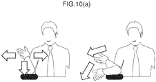
- the configuration may also be such that the direction and number of gestures to be accepted are changed according to the position and posture of the user's hand upon detecting the user's hand placement. For example, as shown in Fig. 10(a) , in a state where the user is placing one's elbow on an elbow rest and raising one's hand, when the user's hand placement is detected, gestures in the leftward, downward and rightward directions are recognized as shown in Fig. 10(b) . This is because, in the user's posture described above, it would be difficult for the user to make a gesture in the upward direction and, therefore, gestures in the 3 directions of leftward, downward and rightward are recognized. Furthermore, the configuration may also be such that the user can set in advance which gestures are to be recognized. Consequently, the user can perform gesture controls based on unrestricted postures.
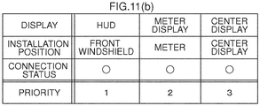
- the configuration may also be such that the location of display and the displayed contents are changed according to the connection status or the installation position of the various devices.
- the gesture control guide is displayed at the center of the screen as shown in Fig. 11(a) .
- the processing of managing the installation position and the connection status of a plurality of displays and deciding the priority is performed. While the basic rule is to display the control guide on the display with the highest priority, in cases where the HUD cannot be used due to a malfunction or other reasons, the control guide is displayed on the display of the next highest priority.
- the time of displaying the guide may be shortened or the amount of information to be displayed may be reduced according to the priority.
- the priority may be set based on various methods; for instance, the priority may be set at the time of factory shipment or time of sales, set by the user with a setting screen (not shown), or programmed in the in-vehicle terminal so that the priority is determined from the characteristics of the display that is connected to the in-vehicle terminal.
- the configuration may also be such that the priority is increased according to the installation position. Consequently, when a device such as the HUD to display the control guide cannot be used, the control guide can be displayed on a substitute device to enable the user to perform controls.
- the configuration may also be such that other control means (voice recognition control, switch control or the like) capable of controlling the in-vehicle device 101 may also be used without limitation to the gesture control.
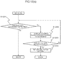
- Fig. 12(a) shows the operation flow in the foregoing case.
- the control guide as shown in Fig. 12(b) is displayed on the external display unit 109.
- An icon 1201 shows that the upper icon can be used for selecting the option of gesture, the middle icon can be used for selecting the option of voice recognition, and the lower icon can be used for selecting the option of switch, respectively.
- the display switches to the screen as shown in Fig. 12(c) .
- the icon 1201 notifies the user that the steering controller control is active by changing the color of the icon.
- the display 1202 shows the candidates of stamps corresponding to the respective buttons of the steering controller. A reply control based on the corresponding stamp is performed according to the pressed button of the steering controller. Note that the display returns to the screen of Fig. 12(b) when a given length of time elapses, or the contact sensor of the steering controller is no longer responding.
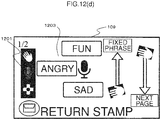
- the display switches to the screen as shown in Fig. 12(d) .
- the icon 1201 shows that the voice recognition is in a standby state
- the display 1203 shows that, by speaking words corresponding to the respective messages, the corresponding stamp can be selected.
- a reply control of the corresponding stamp is performed.
- the icon to be sent may also be displayed alongside the message so that user can know, at a glance, which icon will be sent.
- control means can be switched even midway during their controls if a start trigger of the respective controls is detected.
- a gesture control based on a vertical hand waving in such state is also accepted. Consequently, when the user is to send a reply, the user is not limited to a single control means, and may freely select the control means for performing the reply control according to the driving status, or according to the user's preference.
- the user upon switching the respective control means, by presenting to the user which control means is currently operable and how to perform such control, the user can quickly perform the control intuitively without any hesitation.
- the configuration may also be such that the control contents that can be performed when the user places one's hand are changed according to the operation status of the application being controlled by the in-vehicle device 101.
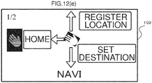
- Fig. 12(e) shows an example of presenting, as navigation-related controls as the available choices, the route setting to the user's home, registration of the current location, and voice-based setting of the destination, when the application running in the background is only a navigation application.
- Fig. 12(f) shows an example of presenting, as available choices, the control of stopping the music, skipping to the next song, or skipping to the previous song when the user places one's hand during music playback.
- Fig. 12(e) shows an example of presenting, as navigation-related controls as the available choices, the route setting to the user's home, registration of the current location, and voice-based setting of the destination, when the application running in the background is only a navigation application.
- Fig. 12(f) shows an example of presenting, as available choices, the control of stopping the
- 12(g) shows an example of presenting, as available choices, the control of listening to the details of traffic jam information, rerouting to the destination, or changing the destination when the user places one's hand upon receiving traffic jam information or the like. Consequently, the user can quickly select various controls according to the status of application being controlled by the in-vehicle device 101 while the user is driving the vehicle.
- the user can, intuitively and quickly, perform controls while looking straight ahead even while driving the vehicle. Specifically, the user can quickly switch the display of the messenger application and perform the control of skipping message while looking straight ahead. Moreover, in cases of controls of selecting a plurality of options, the user can select one's intended option while looking straight ahead and confirming the contents of the available choices. Furthermore, once the user becomes familiar with the controls, the user will be able to select the options without having to view the display, and the user will be able to perform controls more safely and quickly.
- Fig. 13 is a configuration diagram of the in-vehicle device 101 in this embodiment.
- a vehicle information input unit 118, a control means control unit 119, a workload estimation unit 120, and a map DB (database) 121 have been added.
- the vehicle information input unit 118, the control means control unit 119, and the workload estimation unit 120 exhibit the functions as the vehicle information input unit 118, the control means control unit 119, and the workload estimation unit 120 as a result of the in-vehicle device control unit 102 performing operations according to the programs stored in the storage unit (not shown).
- the vehicle information input unit 118 is the part that acquires information related to the vehicle that is being driven, and, for instance, is connected to the vehicle via a CAN (Control Area Network), and acquires information related to vehicle speed, accelerator position, brake position, turn signal, and steering angle.
- CAN Controller Area Network
- the control means control unit 119 controls to which control the control input from the gesture detection unit 104 or the voice recognition unit 116, or the various switch control units should be reflected.
- the workload estimation unit 120 estimates the user's workload in the driving operation. For example, in addition to the various input signals from the vehicle information input unit 118 described above, the workload estimation unit 120 integrates information input from the communication unit 107 (map information, type of road that the vehicle is traveling on, distance to preceding vehicle, and so on), and defines the workload level as four stages (None, Low, Medium, High).
- “None” is a state where the vehicle is waiting at a traffic light or the vehicle is on autopilot and being driven based on ACC (Adaptive Cruise Control) or the like where the driver is not required to perform any special control
- "Low” is a state where the vehicle is being driven on a straight road with no obstacles in the periphery
- “Medium” is a state where the vehicle is being driven at a certain speed or faster and a steering wheel control is constantly required, or a state of making a turn at an intersection
- “High” is a state where the user is required to perform an important driving operation to avoid an accident.
- the map DB 121 is a database which stores map information.
- the operation of the in-vehicle device 101 of this embodiment is now explained in detail.
- the basic operation is the same as the operation explained in Embodiment 1, but this embodiment is unique in that the operation is controlled according to the output of the workload estimation unit 120.
- the in-vehicle device control unit 102 has defined in advance the workload level output from the workload estimation unit 120 and the control means that can be controlled and the displayed contents that can be presented, at the respective workload levels.
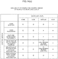
- Fig. 14(a) to Fig. 14(d) show the foregoing definitions.
- Fig. 14(a) shows whether or not the respective control means can be used in the respective workload levels.
- the workload level is "None” or “Low”
- all control means described in Embodiment 1 can be used for sending a reply.
- the workload level is "High”
- all controls are prohibited.
- the workload is "Medium”
- the display of the hand placement control guide and the subsequent selection of options based on a gesture control are prohibited. Because a hand placement control is a control means that forces the user to perform one-handed driving, this control is prohibited in circumstances where the user should concentrate on the driving operation.
- the external display unit 109 of this embodiment displays the current workload level as shown with the icon 1503 of Fig. 15(a).
- Fig. 15(a) shows that the workload level is "Medium", and a display showing that the hand placement control is prohibited, as shown with the icon 1501, is indicated to notify the user that a control using one's hand cannot be performed.
- the user's hand placement is detected in this state, the display or color of the icon 1501 is changed, and a warning sound or warning message is output, to emphasize the fact that no hand placement control may be performed, and to urge the user to immediately stop his/her hand placement.
- the user can comprehend the current workload status, and it is possible to prevent, as much as possible, the user from removing one's hand from the steering wheel for a long time as a result of attempting to display the control guide even though the user is required to perform the steering wheel control.
- free speech reply based on voice recognition that does not require the use of a hand and a hand waving gesture that can be completed with an instant control can be used even when the workload level is "Medium”.
- Fig. 15(b) shows that, among the icons of the three types of control means, the selection control based on hand placement and gesture is prohibited.
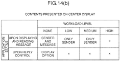
- Fig. 14(b) shows the definitions related to the workload level and the output contents of the center display. Foremost, when the workload level is "None", the messenger application 113 displays the entire text of the message. Moreover, when the user is sending a reply based on basic controls such as touching the control icon on the screen, all options such as the stamp candidates are also displayed. When the workload is "Low” or “Medium”, the text of the message is not displayed, and only the name of the sender of the message is displayed. Moreover, the control system using a touch control is also not displayed.
- the screen of the messenger application 113 is also turned off, and a warning message corresponding to the situation (for instance, "Keep distance!) is displayed.
- the workload level switches to "None" midway during the foregoing control
- the user may also perform such control based on a touch control on the center display in consideration of the status of the control guide displayed on the HUD. For example, as shown in Fig. 16(a) , in a state where the user is performing a stamp reply on the HUD, information of the contents and arrangement of the stamp candidates is maintained and additionally displayed on the center display as shown in Fig. 16(b) .
- the stamp candidates 1601 and the arrangement thereof on the screen of the HUD are maintained, the stamp candidates are displayed on the center display as shown with reference numeral 1602. Furthermore, the contents of 1602 are arranged on the driver's side so that it would be easier for the driver to perform controls, and select the stamp to be sent based on a touch control. Moreover, the remaining stamp candidates are arranged on the screen at a position that is far from the driver's side as shown with 1603.
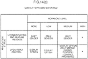
- Fig. 14(c) shows the definitions related to the workload level and the output contents of the HUD. Foremost, when the workload level is "None” or “Low”, the name of the sender is displayed when the message is being read, and the control guide when sending a reply is displayed. When the workload level is “Medium”, a message to the effect that a hand placement control is prohibited is displayed, or the screen of the control is maintained and displayed only when the workload level changes from “Low” to “Medium”. When the workload level is "High”, a warning message corresponding to the situation (for instance, "Keep distance!) is displayed.
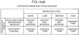
- Fig. 14(d) shows the definitions related to the workload level and the sound output from the speaker.
- the workload level is "None” to “Medium”
- the control sound or the reading voice at such time is output.
- the workload level is "High”
- only a warning sound is output. Note that, even when a message is being read, the output thereof is stopped. The stopped message that was being read is resumed and once again read from the beginning once the workload level becomes lower.
- the configuration may also be such that the user's hand placement detection algorithm and the feedback method are changed according to the workload level. For example, when the workload level is "Low” and the hand placement is detected when the user places one's hand for 0.5 seconds or longer, in cases where the workload level is "None”, the setting is changed such that the hand placement is detected when the user places one's hand for 2 seconds or longer. Furthermore, when the workload level is "None", the feedback of hand placement based on a sound output is discontinued.
- the hand placement detection algorithm which was devised so that the user can perform controls quickly and while looking straight ahead while driving can prevent erroneous detection based on operations other than hand placement operations, such as touch controls, by giving consideration to the fact that touch controls and taking one's eyes off the road are permitted while the vehicle is stopped.
- the user can perform controls based on various means and receive more information when the user has much leeway such as when the vehicle is stopped, and the user can perform safe driving by preventing the user from focusing on other controls other than the driving operation in situations where the user should be concentrating on the driving operation.
- the present invention is not limited thereto, and may also be applied to devices such as a personal computer, digital signage, construction machinery, aircraft, or monitoring operator device that comprise a display unit and a control means.
- Fig. 17 is a configuration diagram of the in-vehicle device 101 in this embodiment.
- a control menu application 1701 a display output unit 1702, a steering controller 1703, a steering contact detection unit 1704, a commander controller 1705, and a commander contact detection unit 1706 have been added.
- the control menu application 1701 is software for displaying a control menu on the display unit 108 and the external display unit 109 according to the programs stored in the storage unit (not shown).
- the display output unit 1702 has a function of outputting video signals to the display unit 108 in cases where a display device that is not built into the in-vehicle device 101 is used as the display unit 108.
- the steering controller 1703 is a switch part that is mounted on the steering wheel, and is used by the user for inputting controls. Moreover, the steering contact detection unit 1704 detects whether the user's hand has come into contact with the switch part of the steering controller 1703.
- the commander controller 1705 is a switch part that is mounted on the in-vehicle instrument panel or center console, and is used by the user for inputting controls. Moreover, the commander contact detection unit 1706 detects whether the user's hand has come into contact with the switch part of the commander controller 1705.
- Fig. 18 shows the appearance of a cockpit in this embodiment.
- the display unit 108 is mounted at the center of the instrument panel, and touch controls can be performed with the touch control unit 106. Moreover, a sensing unit 103 for detecting gestures is provided at the upper right part of the display unit 108.
- the external display unit 109 is configured from an HUD, and can display various types of information while allowing the scenery ahead of the driver (user) to pass therethrough.
- the steering controller 1703 is provided in the steering wheel. Moreover, the commander controller 1705 is provided on the center console.
- the operation of the in-vehicle device 101 of this embodiment is now explained.
- the basic operation is the same as the operation explained in Embodiment 1, but this embodiment is unique in that the displayed contents of the display unit 108 and the external display unit 109 are changed based on the hand waving in the upward direction and the downward direction relative to the sensing unit 103, and that the shape of the control menu and control guide displayed on the external display unit 109 is changed according to the hand motion that is detected by the sensing unit 103.
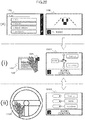
- Fig. 19 shows a state where the displayed contents of the display unit 108 and the external display unit 109 are changed based on the hand waving in the upward direction and the downward direction relative to the sensing unit 103.
- the respective screens of (A), (B) and (C) of Fig. 19 represent the display in the screen mode controlled by the control menu application 1701, and (A) shows an audio control mode, (B) shows a navigation control mode, and (C) shows an air-conditioning control mode.
- the screen of the display unit 108 and the external display unit 109 switches from (A) to (B), from (B) to (C), and from (C) to (A) of Fig. 19 .
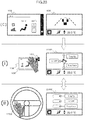
- Fig. 20 shows a state where the user is performing controls based on gestures and the steering controller 1703 in the (B) navigation control mode.
- the gesture control menu 2001 is displayed on the external display unit 109, and, by moving one's hand in one direction among upward, downward and leftward from the hand placement position, the user can select the item corresponding to that direction.
- the steering controller control menu 2002 is displayed as shown in (ii) of Fig. 20 .
- the state shown in (ii) of Fig. 20 shows a state where the user is performing controls based on gestures and the steering controller 1703 in the (B) navigation control mode.
- Fig. 21 , Fig. 22 , and Fig. 23 show the screen transition of the external display unit 109 in the series of operations explained with reference to Fig. 19 and Fig. 20 .
- Fig. 21 shows the screen transition of the (B) navigation control mode
- Fig. 22 shows the screen transition of the (A) audio control mode
- Fig. 23 shows the screen transition of the (C) air-conditioning control mode.
- Fig. 24 shows the detailed movement in the screen of the external display unit 109 in the (B) navigation control mode.
- the gesture control menu 2001 is displayed on the external display unit 109.
- the user moves one's hand in the upward direction from the hand placement position, as shown in 2401 of Fig. 24 , only the item corresponding to the upward direction is displayed for a predetermined time, and, based on this display, the user can confirm that the intended item has been selected.
- a predetermined time elapses from the display of 2401
- the display of the external display unit 109 returns to the state before the user's hand placement. Note that the movement is the same for the steering controller control menu 2002.
- Fig. 26(a) is a table showing the correspondence of the gesture detection status and the control device in the in-vehicle device 101 of this embodiment.
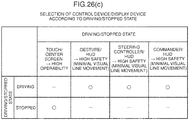
- Fig. 26(c) is a table showing the correspondence of the control device and the display device according to a state where the vehicle is moving and a state where the vehicle is stopped.
- the output information control unit 114 of this embodiment determines the control device and the display device to be used in the control of a predetermined menu according to Fig. 26(a) and Fig. 26(c) .
- the output information control unit 114 determines that the user is attempting to perform a control with a gesture. Moreover, when the user's hand is removed from the sensing unit 103, the output information control unit 114 determines that the user is attempting to perform a control with the steering controller 1703. Note that, for vehicles that are not equipped with the steering controller 1703, the output information control unit 114 may determine that the user is attempting to perform a control with another control device such as a commander controller 1705 that is equipped in the vehicle. Based on the foregoing determination, the output information control unit 114 instructs the control menu application 1701 to output a predetermined screen. It is thereby possible to display the control menu and control guide that are suitable for the control device to be controlled by the user, and an effect is yielded in that the user can smoothly perform controls using the intended control device.
- the output information control unit 114 determines that the user is attempting to perform controls by using gestures, the steering controller 1703 and the commander controller 1705 while the vehicle is moving, the output information control unit 114 displays the control menu on the external display unit 109 (HUD). Consequently, because the user can visually confirm the control menu with minimal line of sight movement from the state of visually recognizing the forward view of the vehicle, an effect is yielded in that the influence on the driving operation caused by the control of the control menu can be suppressed.
- HUD external display unit 109
- a touch panel with high controllability which enables detailed controls with the user's fingertips may also be permitted.
- a touch panel with high controllability which enables detailed controls with the user's fingertips may also be permitted.
- a touch panel with high controllability which enables detailed controls with the user's fingertips may also be permitted.
- a touch panel with high controllability which enables detailed controls with the user's fingertips may also be permitted.
- a touch panel in a state where the steering controller control menu 2002 is being displayed on the external display unit 109
- a advanced menu as shown in 2501 of Fig. 25 may be displayed on the display unit 108, and controls may be performed based on touch control.
- the display of the display unit 108 may be turned off, and the steering controller control menu 2002 may be displayed once again on the external display unit 109. Consequently, an effect is yielded in that the user can switch to a touch panel control and perform controls efficiently based on a touch control in circumstances where the driving operation will not be hindered, such as when the
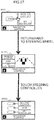
- the display of the steering controller control menu 2002 may feel bothersome when the user wishes to perform the driving operation with the hand that was returned to the steering.
- a simplified menu in which the part where the menu is to be displayed in the external display unit 109 is reduced in size as shown in 2701 of Fig. 27 may be displayed, and the steering controller control menu 2002 may be displayed when the steering contact detection unit 1704 detects that the user has touched the switch of the steering controller 1703.
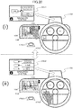
- Fig. 28 shows the appearance of the control of the in-vehicle device 101 in this embodiment.
- a screen where the commander control menu 2801 is displayed on the external display unit 109 when the user places one's hand near the commander controller 1705 has been added.
- a camera is used as the sensing unit 103 as shown in Fig. 9 .
- the sensing unit 103 of this embodiment detects in which direction the user's hand is moving in the periphery of the sensing unit 103. Note that, so as long as it is possible to detect in which direction the user's hand is moving, the sensing unit 103 may be a sensing device other than a camera.
- Fig. 28 shows a state where the user is performing controls based on gestures, the steering controller 1703 and the commander controller 1705 in the (B) navigation control mode.
- the steering controller control menu 2002 is displayed as shown in (i) of Fig. 28 .
- the control menu 2801 of the commander controller 1705 is displayed as shown in (ii) of Fig. 28 .
- the user can select one item in correspondence with the rotary controlled equipped in the commander controller 1705.
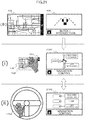
- Fig. 26(b) is a table showing the selection of the control device according to the position and moving direction of the hand in the in-vehicle device 101 of this embodiment.
- the output information control unit 114 of this embodiment decides the control device to be used for the control of a predetermined menu according to Fig. 26(b) .
- the output information control unit 114 determines that the user is attempting to perform a control with a gesture. Moreover, when the user's hand moves from the sensing unit 103 in the direction or to the position of the steering controller 1703, the output information control unit 114 determines that the user is attempting to perform the control with the steering controller 1703. Furthermore, when the user's hand moves from the sensing unit 103 in the direction or to the position of the commander controller 1705, the output information control unit 114 determines that the user is attempting to perform the control with the commander controller 1705. Note that the steering controller 1703 and the commander controller 1705 may be other control devices equipped in the vehicle.
- the output information control unit 114 instructs the control menu application 1701 to output a predetermined screen. It is thereby possible to display the control menu and control guide that are suitable for the control device to be controlled by the user, and an effect is yielded in that the user can smoothly perform controls using the intended control device.
- the determination may also be made based on the user's finger-pointing direction detected by the sensing unit 103 rather than based on the direction or position that the user's hand moved from the sensing unit 103.
- the sensing unit 103 may detect that the user pointed one's finger to the air-conditioning control panel 2901 in the state shown in (i) of Fig. 29 , and the steering controller control menu 2302 for air-conditioning control may be displayed on the external display unit 109 based on the foregoing detection. Consequently, an effect is yielded in that the intended control menu can be displayed even more smoothly without the user having to place one's hand over the sensing unit 103 even once.
Landscapes
- Engineering & Computer Science (AREA)
- Theoretical Computer Science (AREA)
- General Engineering & Computer Science (AREA)
- Physics & Mathematics (AREA)
- General Physics & Mathematics (AREA)
- Human Computer Interaction (AREA)
- Mechanical Engineering (AREA)
- Transportation (AREA)
- Chemical & Material Sciences (AREA)
- Combustion & Propulsion (AREA)
- Multimedia (AREA)
- Health & Medical Sciences (AREA)
- General Health & Medical Sciences (AREA)
- Optics & Photonics (AREA)
- Audiology, Speech & Language Pathology (AREA)
- Computer Vision & Pattern Recognition (AREA)
- Psychiatry (AREA)
- Social Psychology (AREA)
- User Interface Of Digital Computer (AREA)
- Instrument Panels (AREA)
Abstract
Description
- The present invention relates to an information processing device.
-
PTL 1 describes a control device of in-vehicle equipment which superimposes and displays, on a head up display (HUD), the control menu of the in-vehicle equipment and the projected image of the driver's hand placed on the control unit, and thereby allows the driver to control the control unit while viewing the projected image to simplify and facilitate the selection control of the in-vehicle equipment so that such control will not interfere with the driving of the vehicle. - [PTL 1] Japanese Laid-Open Patent Publication No.
2010-215194 - Nevertheless, when controlling the in-vehicle equipment while driving a vehicle, with the technology described in
PTL 1, because the control menu is constantly displayed on the HUD, such display of the control menu may interfere with the driving operation. Moreover, in order to perform controls, a dedicated device for performing controls must be installed somewhere within the vehicle, and, in addition to increased costs, there are restrictions in the mounting of such device. Furthermore, even in cases of using a voice-only interface, processing time of the processing required for voice recognition and time for listening to the emitted voice are required, and the controllability and convenience are impaired. - According to the present invention, an in-vehicle device, comprises: a gesture detection unit which recognizes a position of a user's hand located within a predetermined range; an output information control unit which controls output information to be output to a display unit; and an in-vehicle device control unit which receives an input from a control unit equipped in a vehicle and thereby controls the in-vehicle device, wherein: when the gesture detection unit detects that the user's hand has been placed at a predetermined position for a given length of time, the output information control unit triggers the display unit to display candidates of an operation to be executed by the in-vehicle device control unit by associating the candidates with motions of the user's hand; and when the gesture detection unit detects that the user's hand has been placed at the predetermined position for a given length of time and the user's hand has thereafter been moved from the predetermined position, the output information control unit changes a selection method or a control guide of the operation to be executed by the in-vehicle device control unit, which is displayed on the display unit, to subject matter which matches the control unit.
- According to the present invention, it is possible to improve the safety and controllability of the control of in-vehicle equipment by a driver who is driving a vehicle.
-
- [
Fig. 1] Fig. 1 is a configuration diagram of an in-vehicle device in the first embodiment of the present invention. - [
Fig. 2(a)] Fig. 2(a) shows an example of an installation position of a sensing unit. - [
Fig. 2(b)] Fig. 2(b) shows an example of gesture detection areas. - [
Fig. 2(c)] Fig. 2(c) shows an example of gesture detection areas. - [
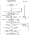
Fig. 3(a)] Fig. 3(a) shows an example of an operation flow in the first embodiment. - [
Fig. 3(b)] Fig. 3(b) shows an example of an operation flow in the first embodiment. - [
Fig. 4(a)] Fig. 4(a) shows a display example of a display unit and an external display unit. - [
Fig. 4(b)] Fig. 4(b) shows a display example of a display unit and an external display unit. - [
Fig. 4(c)] Fig. 4(c) shows a display example of a display unit and an external display unit. - [
Fig. 4(d)] Fig. 4(d) shows a display example of a display unit and an external display unit. - [
Fig. 5(a)] Fig. 5(a) shows a display example of an external display unit. - [
Fig. 5(b)] Fig. 5(b) shows a display example of an external display unit. - [
Fig. 5(c)] Fig. 5(c) shows a display example of an external display unit. - [
Fig. 5(d)] Fig. 5(d) shows a display example of an external display unit. - [
Fig. 6] Fig. 6 shows a display example of a display unit and an external display unit. - [
Fig. 7(a)] Fig. 7(a) shows a display example of an external display unit. - [
Fig. 7(b)] Fig. 7(b) shows a display example of an external display unit. - [
Fig. 8(a)] Fig. 8(a) shows an installation example of a sensing unit. - [
Fig. 8(b)] Fig. 8(b) shows a correspondence example of operations according to the position of a sensing unit. - [
Fig. 9] Fig. 9 shows an example of a sensing unit and shapes of a user's hand. - [
Fig. 10(a)] Fig. 10(a) shows examples of the manner of waving a user's hand. - [
Fig. 10(b)] Fig. 10(b) shows a display example of an external display unit. - [
Fig. 11(a)] Fig. 11(a) shows a display example of a display unit. - [
Fig. 11(b)] Fig. 11(b) shows an example of display locations of the displayed contents. - [
Fig. 11(c)] Fig. 11(c) shows an example of display locations of the displayed contents. - [
Fig. 12(a)] Fig. 12(a) shows an example of an operation flow. - [
Fig. 12(b)] Fig. 12(b) shows a display example of an external display unit. - [
Fig. 12(c)] Fig. 12(c) shows a display example of an external display unit. - [
Fig. 12(d)] Fig. 12(d) shows a display example of an external display unit. - [
Fig. 12(e)] Fig. 12(e) shows a display example of an external display unit. - [
Fig. 12(f)] Fig. 12(f) shows a display example of an external display unit. - [
Fig. 12(g)] Fig. 12(g) shows a display example of an external display unit. - [
Fig. 13] Fig. 13 shows a configuration diagram of an in-vehicle device in the second embodiment. - [
Fig. 14(a)] Fig. 14(a) shows an example of a control pattern according to a workload level. - [
Fig. 14(b)] Fig. 14(b) shows an example of a control pattern according to a workload level. - [
Fig. 14(c)] Fig. 14(c) shows an example of a control pattern according to a workload level. - [
Fig. 14(d)] Fig. 14(d) shows an example of a control pattern according to a workload level. - [
Fig. 15(a)] Fig. 15(a) shows a display example of an external display unit. - [
Fig. 15(b)] Fig. 15(b) shows a display example of an external display unit. - [
Fig. 16(a)] Fig. 16(a) shows a display example of a display unit. - [
Fig. 16(b)] Fig. 16(b) shows a display example of an external display unit. - [
Fig. 17] Fig. 17 shows a configuration diagram of an in-vehicle device in the third embodiment of the present invention. - [
Fig. 18] Fig. 18 shows an appearance example of a cockpit. - [
Fig. 19] Fig. 19 shows a display example of a display unit and an external display unit. - [
Fig. 20] Fig. 20 shows an example of a control method based on gestures and a steering controller. - [
Fig. 21] Fig. 21 shows a display example of an external display unit. - [
Fig. 22] Fig. 22 shows a display example of an external display unit. - [
Fig. 23] Fig. 23 shows a display example of an external display unit. - [
Fig. 24] Fig. 24 shows an example of an operation flow. - [
Fig. 25] Fig. 25 shows an example of a control method based on a steering controller and a touch panel. - [
Fig. 26(a)] Fig. 26(a) shows a table indicating a selection method of a control device according to the approach of a user's hand to a specific device. - [
Fig. 26(b)] Fig. 26(b) shows a table indicating a selection method of a control device according to the position and moving direction of a user's hand. - [
Fig. 26(c)] Fig. 26(c) shows a table indicating a selection method of a control device and a display device according to the driving/stopped state. - [
Fig. 27] Fig. 27 shows an example of an operation flow. - [
Fig. 28] Fig. 28 shows an example of a control method based on a steering controller and a command controller. - [
Fig. 29] Fig. 29 shows an example of a control method based on a gesture and a steering controller. - Embodiments of the present invention are now explained in detail with reference to the appended drawings.
-
Fig. 1 is a configuration diagram of an in-vehicle device 101 in this embodiment. An in-vehicledevice control unit 102 is the part that controls the overall operation of the in-vehicle device 101, and realizes the functions as amessenger application 113 and an outputinformation control unit 114 by performing operations according to programs related to themessenger application 113 and the outputinformation control unit 114 stored in a storage unit (not shown). Note that the in-vehicle device 101 may also be loaded with applications other than themessenger application 113 and the outputinformation control unit 114, and these programs may also be stored in a storage unit at the time of factory shipment, or may be stored in the storage unit through the user's selection via acommunication unit 107, or via an externally connected IF (not shown) such as a USB terminal. Moreover, the in-vehicledevice control unit 102 controls the basic operation as a car navigation system, and additionally controls the contents to be output based on the various types of input information. - A
sensing unit 103 is the part that detects the distance between the user's hand and a sensor, and detects the waving (or moving) of the user's hand, and is configured, for example, from a sensor such as an infrared distance sensor, a laser distance sensor, an ultrasonic distance sensor, a distance image sensor, an electrolytic sensor, or an image sensor, a microcomputer which performs data processing, and software that runs on the microcomputer. There is no particular limitation regarding the sensors to be used in thesensing unit 103, and any sensor may be used so as long as it has a function of being able to obtain a signal for detecting the distance to the user's hand and detecting the waving of the user's hand. - Based on the sensor data obtained from the
sensing unit 103, agesture detection unit 104 detects whether the user placed one's hand at a certain position, and whether a predetermined gesture (for instance, hand waving motion in a vertical/horizontal direction) was performed. For example, the user's hand placement is detected by analyzing whether a predetermined sensor value has continued for a given length of time, and the gesture operation is detected by analyzing the difference between the response times of the hand detection results between a plurality of sensors. - A
switch control unit 105 is a hardware switch for controlling the in-vehicle device, and may be a button-pressing type, or a jog-dial type. - A
touch control unit 106 sends the touched coordinates to the in-vehicledevice control unit 102, and controls the in-vehicle device. - A
microphone 115 acquires sounds within the vehicle. - A
voice recognition unit 116 converts the speech from the input sound data into a text code string. - A
communication unit 107 is connected to an outside network, and inputs/outputs various types of information. For example, thecommunication unit 107 inputs navigation-related information and sends/receives messages. - An external
switch control unit 117 is a switch control unit installed at a location that is different from the location of the in-vehicle device 101, and considered may be a steering switch mounted near the steering wheel, or a commander switch mounted on the center console of the vehicle. - A
display unit 108 is a device for presenting video information to the user, and, for instance, is a device comprising a display device such as an LCD (Liquid Crystal Display), and an arithmetic processing device and a memory which are required for the display processing of video contents and GUI (Graphical User Interface). - An
external display unit 109 is a display that is installed at a location within the vehicle which is different from the location of the in-vehicle device 101 and displays videos. For example, theexternal display unit 109 may be a head up display (HUD) mounted at the anterior of the driver's seat. An HUD can display various types of information while allowing the scenery ahead of the driver (user) to pass therethrough.
Asound output unit 110 is the part that outputs sounds or voices.
Aspeaker 111 outputs sound from thesound output unit 110. - A tactile IF
output unit 112 is the part that conveys some type of tactile information to the user, and, for instance, is configured from an ultrasonic array formed from a plurality of ultrasonic elements, and conveys the spatial pressure of an arbitrary distance of the device. Otherwise, an air blower may be provided to yield the same effect. Moreover, the tactile IFoutput unit 112 may also be configured from an oscillator mounted near the steering wheel to cause the entire steering wheel to vibrate, and there is no particular limitation regarding the constituent elements. - A
messenger application 113 sends and receives messages to and from thecommunication unit 107, stores the input messages, and outputs such messages. Moreover, when sending a message, themessenger application 113 sends the outbound message to thecommunication unit 107. - An output
information control unit 114 controls the contents to be output to thedisplay unit 108 or theexternal display unit 109. -
Fig. 2(a) shows an installation example of thesensing unit 103. Thesensing unit 103 is mounted on the driver's side in a right-side steering wheel vehicle relative to thedisplay unit 108, and can detect the distance information of an object from the spot of the sensor element, and the movement of the object. Consequently, as shown in the lower diagram ofFig. 2(a) , the space between the in-vehicle device 101 and the user is divided into a plurality of areas, and in which area the user's hand exists can be detected in detail. As shown in the lower diagram, the space is divided into anarea 201 that is close to the sensor position, and anarea 202 that is even closer to the sensor position. Note that the number of sensor elements, installation position, and areas to be detected are not limited to this example. - The operation of the in-
vehicle device 101 is now explained in detail with reference to the operation flow shown inFig. 3(a) . Note that, when themessenger application 113 is to output videos or voices to output units such as thedisplay unit 108, theexternal display unit 109, and thespeaker 111, themessenger application 113 sends video or voice information to the outputinformation control unit 114, and the outputinformation control unit 114 determines whether or not to output the received information to the foregoing output units. However, in order to simplify the ensuing explanation, expressions such as "themessenger application 113 outputs videos to thedisplay unit 108" and "themessenger application 113 outputs voices" will be used. - Foremost, the operation of the in-
vehicle device 1 is started when the engine of the vehicle is started. The outputinformation control unit 114 displays a navigation screen and anicon 401 of themessenger application 113 on the display unit 108 (center display in this example) as shown inFig. 4(a) when the operation is started. Themessenger application 113 is executed in the background by the in-vehicledevice control unit 102 together with the activation of the in-vehicle device 101, and is activated by the outputinformation control unit 114 when thetouch control unit 106 detects a touch control of touching theicon 401, or thegesture detection unit 104 detects the user's prescribed gesture operation (for instance, hand waving in the leftward direction in front of the sensor). - Moreover, the output
information control unit 114 displays a navigation screen and a screen related to themessenger application 113 on the external display unit 109 (HUD in this example) when the operation is started. When a message is received from the outside via the communication unit 107 (S301), themessenger application 113 outputs a sound effect to notify an incoming message, displays the total number of received messages on theexternal display unit 109 as shown with anicon 402 ofFig. 4(b) , and notifies the user that the number of unread messages has increased. - When the
gesture detection unit 104, thevoice recognition unit 116, theswitch control unit 105, the externalswitch control unit 117, or thetouch control unit 106 subsequently detects that the user performed a control for activating the messenger application 113 (S303), the outputinformation control unit 114 switches the display to a screen for using the application by activating themessenger application 113 as shown inFig. 4(c) (S304). Themessenger application 113 thereafter outputs voice information which reads the received messages in order from the oldest message (S305).Fig. 4(c) is a display example when using the half screen of thedisplay unit 108 as the screen of themessenger application 113. - When the
touch control unit 106 detects that the user touched an area of anicon 403 onFig. 4(c) , themessenger application 113 causes thedisplay unit 108 to display a screen for performing the respective controls of stamp reply, fixed phrase reply, free speech reply, and message return/forward from the left side of the area of theicon 403. Moreover, while the voice information is being output in S305, themessenger application 113 causes theexternal display unit 109 to display the current number of unread messages as with anicon 404 in the lower diagram ofFig. 4(c) , and the name of the sender of the message that is being read. When thegesture detection unit 104 detects that the user performed a prescribed gesture operation (for instance, hand waving motion in an upward or downward direction) while the message is being read (S306: Yes), themessenger application 113 causes thespeaker 111 to output voice information so that the latest message among the unread messages is read (S308). - When no such gesture operation is detected, the
messenger application 113 continues to output the voice information so that the unread messages are read in order from the oldest message (S307), and, when the reading of the latest message is finished, enters a reply control standby state while causing thedisplay unit 108 and theexternal display unit 109 to continue displaying the last sender as shown inFig. 4(d) (S309). In the reply control standby state, themessenger application 113 displays anicon 501, which indicates that a gesture-based reply control can be performed, on theexternal display unit 109 as shown inFig. 5(a) . - When a given length of time (for instance, 0.5 seconds) has elapsed in a state where the user's hand is placed in the
area 202 ofFig. 2(a) (S310: Yes), it is determined that the conditions for starting the control have been satisfied, and theexternal display unit 109 switches its screen such that the menu as the control guide of the reply control will be displayed in a manner of sliding from the right side of the screen, and a sound effect to notify the appearance of the menu is also output (S311). Note that, when the user's hand is detected in thearea 202, themessenger application 113 may also output a sound effect for allowing the user to aurally recognize such detection, and move theicon 501 to the right side or change the color of the icon as shown inFig. 5(b) for allowing the user to also visually recognize such detection. Moreover, when the user's hand is detected in thearea 201 and not in thearea 202 and a given length of time (for instance, 0.3 seconds) has elapsed, themessenger application 113 outputs a sound effect to notify the user that the hand placement position is erroneous. By this means, when placing one's hand, the user can perform hand placement controls while looking ahead without having to shift one's line of sight to his/her hand. -
Fig. 2(b) andFig. 2(c) are diagrams showing in detail the relation of the detection state of the user's hand and the output of sound effects.Fig. 2(b) andFig. 2(c) respectively represent the time axis and the sensor value of thesensing unit 103, and show the boundary for determining whether the sensor value falls within thearea 201 or thearea 202. -
Fig. 2(b) shows an example where the user stretches one's hand toward thearea 202, and places one's hand in thearea 202 for a given length of time. When thegesture detection unit 104 detects that the user's hand entered thearea 201, thegesture detection unit 104 outputs asound effect 1. Next, when thegesture detection unit 104 detects that the user's hand entered thearea 202, thegesture detection unit 104 outputs asound effect 2. When thegesture detection unit 104 continues to detect that the user's hand is in thearea 202 for a time T1 or longer (for instance, for 0.5 seconds or longer), thegesture detection unit 104 outputs asound effect 3, and switches the screen of theexternal display unit 109 as explained with reference to S311. -
Fig. 2(c) shows an example where the user continues to place one's hand in thearea 201. Thegesture detection unit 104 outputs thesound effect 1 upon detecting that the user's hand entered thearea 201, and outputs asound effect 4 upon detecting that the user's hand is in thearea 201 for a time T2 or longer (for instance, for 0.3 seconds or longer). If the user's hand is subsequently detected in thearea 202, the same process as the example ofFig. 2(b) is performed. In the ensuing explanation, the control of placing one's hand in thearea 202 for the time T1 or longer is sometimes simply referred to as "hand placement". -
Fig. 5(c) shows an example of a case where a control menu, which enables the user to perform a stamp reply, is displayed. Theicon 502 is a control guide which means that, when the user performs a gesture in the upward, leftward or downward direction while placing one's hand over theicon 502, the corresponding stamp can be selected. Moreover, the display of 1/2 at the upper left corner refers to the total number of pages of the displayed stamp candidates, and the current page. When a gesture in the upward, leftward or downward direction is detected in this state (S312: Yes), themessenger application 113 selects the stamp corresponding to that direction and sends a reply (S313), and then once again makes a transition to the reply control standby state S309. - When no gesture is detected and the user's hand leaves the area 202 (S312: No, S314: Yes), the displayed contents of the
external display unit 109 are switched to the displayed contents shown inFig. 5(d) (S315). Theicon 503 represents the stamp candidates that can currently be selected. Theicon 504 represents that the corresponding control will be performed when the gesture control corresponding to the displayed direction (upward hand waving or downward hand waving) is performed. Moreover, the display of "fixed phrase" means switching the reply method to a fixed phrase reply, and the display of "next page" means switching the stamp candidates from those displayed with theicon 503 to the next candidate group. If numerous options are displayed at once, the user will spend too much time selecting the option despite the user driving a vehicle, and may lead to the user's lack of concentration in driving the vehicle. Thus, in this embodiment, only the 3 options positioned at the top, left and bottom are provided, and, by providing gestures for increasing the options of the stamp to be sent, more than 3 options can be provided to the user. When a corresponding gesture control is detected (S316: Yes), a corresponding control is executed (S317). When a gesture is not detected (S316: No) and the placement of the user's hand in thearea 202 is detected (S318: Yes), themessenger application 113 makes a transition to the state of S311, and once again enters the stamp selection state. - When the user's hand is not detected and a given period of time (for instance, 10 seconds) elapses in that state (S318: No, S319: Yes), the
messenger application 113 erases the control guide from the screen of theexternal display unit 109, and makes a transition to the reply control standby state of S309 (S320). When a reply is sent, as shown inFig. 6 , themessenger application 113 displays the contents of the reply control result (selected stamp in this example) on thedisplay unit 108, displays the name of the user who sent the reply on theexternal display unit 109, and reads the reply message. - Note that this operation flow is an explanation of a representative example of the operation of the in-
vehicle device 101 of the present invention, and the operation, display, and sound effect are not limited to this example. For example, while the foregoing explanation was provided by assuming the sending of a reply when using themessenger application 113, the present invention is not limited thereto, and can be applied to the overall control of the in-vehicledevice control unit 102 of selecting a plurality of options.Fig. 3(b) shows a simplified version of the operation flow. The basic operation is as explained above, and, while the explanation of the operation in each step is the same as those with the same step number ofFig. 3(a) , S316 ofFig. 3(b) does not have to be limited to vertical hand waving, and may also accept various controls, such as the control using a steering switch. - Moreover, when a message is received from the outside, the configuration may also be such that the message is read at the same time that the message is received, or the contents of the received message may be displayed on the
external display unit 109. Consequently, it will be easier for the user to comprehend the message. Moreover, the configuration may also be such that at the reply control standby it can be accepted at any time without waiting for the reading of the latest message to be finished. Consequently, the user may send a reply at any time. Moreover, with regard to thearea 202 where the user's hand is to be placed, the configuration may be such that the tactile sensation is presented in mid air in such area by the tactile IFunit 112. - For example, the configuration may be such that the pressure points of an ultrasonic device array appear on the boundary of the areas, or a tactile sensation is given on the vertical line of the area using an air blower. Consequently, the user can place one's hand in the area while looking straight ahead, and can send a reply safely even though such control is performed while driving. Moreover, while the transition is made to the stamp reply control after the user's hand placement is detected in this example, the configuration may also be such that the transition is made to the reply method selection state (stamp, fixed phrase, free speech or the like) before the foregoing transition. Consequently, the user can select one's preferred reply method at the time that the reply control is started.
- Moreover, while the user's gesture is accepted after the user's hand placement is detected and the control guide is displayed on the
external display unit 109 in this example, the user's gesture may also be accepted from a given length of time before (for instance, 0.2 seconds before) displaying the control guide. Consequently, once the user becomes familiar with the control and learns which gesture corresponds to which control, the control can be performed without having to display unnecessary screens on theexternal display unit 109, and the control time can also be shortened. - Moreover, in S319, while the lapse of a given length of time was measured, the configuration may also be such that the process proceeds to S320 upon detecting a predetermined control (for instance, hand waving motion in the left direction, switch control, or the like) prior to satisfying the foregoing condition. Consequently, the user can switch the display of the
external display unit 109 to a navigation screen at one's desired timing. - Moreover, the control guide displayed on the
external display unit 109 and the gesture direction are not limited to 3 directions, and arbitrary directions and number of directions may be used. Here, directions in which the gesture control can be easily performed while sitting in the driver's seat may be set. For example, if the user's gesture is made in the direction of the steering wheel, the user's hand may hit the steering wheel while driving the vehicle and, therefore, a gesture in such direction is excluded as an option. Thus, the configuration may be such that whether the steering wheel of the vehicle to be driven is a right-side steering wheel or a left-side steering wheel can be set in advance using the setting screen and, when the steering wheel is a left-side steering wheel, the control guide displayed on theexternal display unit 109 indicates the 3 directions of upward, downward and rightward as shown inFig. 7(a) andFig. 7(b) . Note thatFig. 7(a) andFig. 7(b) correspond toFig. 5(c) andFig. 5(d) , respectively. - Moreover, because the hand to be used for the gesture will change depending on the location where the steering wheel is mounted, the display and direction of the icons are also changed. Furthermore, because the visibility of the various icons will change depending on the position of the steering wheel, the use may also individually change the setting. Consequently, the user can perform controls based on gestures that can be easily performed according to the steering wheel installation position for each vehicle model, and the user can effortlessly perform various controls based on gestures while sitting in the driver's seat.
- Moreover, the configuration may also be such that the placement of the user's hand can be performed at a plurality of locations, without limiting the hand placement position to one location as in this example. For example, as shown in
Fig. 8(a) , three sensors are installed at three locations. Here, the reply method may be decided depending on which sensor detected the user's hand placement. As shown inFig. 8(b) , a stamp reply is sent when thesensor 103A detects the user's hand placement, a fixed phrase reply is sent when thesensor 103B detects the user's hand placement, and a free speech reply is sent when thesensor 103C detects the user's hand placement. Consequently, the user can quickly select the reply method and perform the reply control. The user may also designate in advance which sensor corresponds to which method. - Moreover, the configuration may also be such that a camera is used for the
sensing unit 103 as shown inFig. 9 to detect the approach and gesture of the user's hand. The images of predetermined hand shapes are learned in advance, and the user's hand placement is detected from the pattern recognition of the learned data, irrespective of the distance and position of the user's hand. Here, a plurality of hand shapes may be detected during the user's hand placement (901A to 903C), and the reply method may thereby be selected. Consequently, the user will be able to start the reply control without reaching out one's hand in front of thesensing unit 103 and performing any gesture operation. - Furthermore, the configuration may also be such that the direction and number of gestures to be accepted are changed according to the position and posture of the user's hand upon detecting the user's hand placement. For example, as shown in
Fig. 10(a) , in a state where the user is placing one's elbow on an elbow rest and raising one's hand, when the user's hand placement is detected, gestures in the leftward, downward and rightward directions are recognized as shown inFig. 10(b) . This is because, in the user's posture described above, it would be difficult for the user to make a gesture in the upward direction and, therefore, gestures in the 3 directions of leftward, downward and rightward are recognized. Furthermore, the configuration may also be such that the user can set in advance which gestures are to be recognized. Consequently, the user can perform gesture controls based on unrestricted postures. - Moreover, while the control menu of the reply control is displayed on the
external display unit 109 in this example, the configuration may also be such that the location of display and the displayed contents are changed according to the connection status or the installation position of the various devices. For example, when the HUD is not connected, the gesture control guide is displayed at the center of the screen as shown inFig. 11(a) . Here, as shown inFig. 11(b) , the processing of managing the installation position and the connection status of a plurality of displays and deciding the priority is performed. While the basic rule is to display the control guide on the display with the highest priority, in cases where the HUD cannot be used due to a malfunction or other reasons, the control guide is displayed on the display of the next highest priority. Here, the time of displaying the guide may be shortened or the amount of information to be displayed may be reduced according to the priority. The priority may be set based on various methods; for instance, the priority may be set at the time of factory shipment or time of sales, set by the user with a setting screen (not shown), or programmed in the in-vehicle terminal so that the priority is determined from the characteristics of the display that is connected to the in-vehicle terminal. - Furthermore, when a carry-in external device (smartphone or the like) is connected to the in-
vehicle device 101 as shown inFig. 11(c) , the configuration may also be such that the priority is increased according to the installation position. Consequently, when a device such as the HUD to display the control guide cannot be used, the control guide can be displayed on a substitute device to enable the user to perform controls. - Moreover, in the reply control of S311 onward in
Fig. 3(a) orFig. 3(b) , the configuration may also be such that other control means (voice recognition control, switch control or the like) capable of controlling the in-vehicle device 101 may also be used without limitation to the gesture control.Fig. 12(a) shows the operation flow in the foregoing case. After the step of S316, when a preparatory movement of the user attempting to perform certain control means is detected (S1201: Yes), the control guide corresponding to such operation is displayed on the external display unit 109 (S1202). Subsequently, when the selection control is executed (S1203: Yes), a reply based on the selected option is performed (S1204). Specifically, upon making a transition to the state of S315, the control guide as shown inFig. 12(b) is displayed on theexternal display unit 109. Anicon 1201 shows that the upper icon can be used for selecting the option of gesture, the middle icon can be used for selecting the option of voice recognition, and the lower icon can be used for selecting the option of switch, respectively. - When it is detected that the user will perform a steering controller control (for instance, an arbitrary button of the steering switch is pressed once, or a contact sensor is mounted on the switch surface and a response thereof is obtained), the display switches to the screen as shown in
Fig. 12(c) . Theicon 1201 notifies the user that the steering controller control is active by changing the color of the icon. Thedisplay 1202 shows the candidates of stamps corresponding to the respective buttons of the steering controller. A reply control based on the corresponding stamp is performed according to the pressed button of the steering controller. Note that the display returns to the screen ofFig. 12(b) when a given length of time elapses, or the contact sensor of the steering controller is no longer responding. - Meanwhile, when it is detected that the user will perform voice recognition (for instance, a voice recognition start switch is pressed), the display switches to the screen as shown in
Fig. 12(d) . Theicon 1201 shows that the voice recognition is in a standby state, and thedisplay 1203 shows that, by speaking words corresponding to the respective messages, the corresponding stamp can be selected. When the result of voice recognition coincides with one of the options, a reply control of the corresponding stamp is performed. In the example ofFig. 12(d) , while only messages such as "I'm having fun" corresponding to the icon are displayed, the icon to be sent may also be displayed alongside the message so that user can know, at a glance, which icon will be sent. When voice recognition is used, because the user can select the stamp to be sent without removing one's hand from the steering wheel, this will further contribute to safe driving. - Note that the three types of control means can be switched even midway during their controls if a start trigger of the respective controls is detected. Moreover, in a control state based on switch control and voice recognition, a gesture control based on a vertical hand waving in such state is also accepted. Consequently, when the user is to send a reply, the user is not limited to a single control means, and may freely select the control means for performing the reply control according to the driving status, or according to the user's preference. Moreover, upon switching the respective control means, by presenting to the user which control means is currently operable and how to perform such control, the user can quickly perform the control intuitively without any hesitation.
- Moreover, the configuration may also be such that the control contents that can be performed when the user places one's hand are changed according to the operation status of the application being controlled by the in-
vehicle device 101.Fig. 12(e) shows an example of presenting, as navigation-related controls as the available choices, the route setting to the user's home, registration of the current location, and voice-based setting of the destination, when the application running in the background is only a navigation application.Fig. 12(f) shows an example of presenting, as available choices, the control of stopping the music, skipping to the next song, or skipping to the previous song when the user places one's hand during music playback.Fig. 12(g) shows an example of presenting, as available choices, the control of listening to the details of traffic jam information, rerouting to the destination, or changing the destination when the user places one's hand upon receiving traffic jam information or the like. Consequently, the user can quickly select various controls according to the status of application being controlled by the in-vehicle device 101 while the user is driving the vehicle. - Based on the in-
vehicle device 101 according to the first embodiment of the present invention described above, the user can, intuitively and quickly, perform controls while looking straight ahead even while driving the vehicle. Specifically, the user can quickly switch the display of the messenger application and perform the control of skipping message while looking straight ahead. Moreover, in cases of controls of selecting a plurality of options, the user can select one's intended option while looking straight ahead and confirming the contents of the available choices. Furthermore, once the user becomes familiar with the controls, the user will be able to select the options without having to view the display, and the user will be able to perform controls more safely and quickly. -
Fig. 13 is a configuration diagram of the in-vehicle device 101 in this embodiment. In comparison to the configuration diagram ofFig. 1 , a vehicle information input unit 118, a control meanscontrol unit 119, aworkload estimation unit 120, and a map DB (database) 121 have been added. The vehicle information input unit 118, the control meanscontrol unit 119, and theworkload estimation unit 120 exhibit the functions as the vehicle information input unit 118, the control meanscontrol unit 119, and theworkload estimation unit 120 as a result of the in-vehicledevice control unit 102 performing operations according to the programs stored in the storage unit (not shown). - The vehicle information input unit 118 is the part that acquires information related to the vehicle that is being driven, and, for instance, is connected to the vehicle via a CAN (Control Area Network), and acquires information related to vehicle speed, accelerator position, brake position, turn signal, and steering angle.
- The control means
control unit 119 controls to which control the control input from thegesture detection unit 104 or thevoice recognition unit 116, or the various switch control units should be reflected. - The
workload estimation unit 120 estimates the user's workload in the driving operation. For example, in addition to the various input signals from the vehicle information input unit 118 described above, theworkload estimation unit 120 integrates information input from the communication unit 107 (map information, type of road that the vehicle is traveling on, distance to preceding vehicle, and so on), and defines the workload level as four stages (None, Low, Medium, High). "None" is a state where the vehicle is waiting at a traffic light or the vehicle is on autopilot and being driven based on ACC (Adaptive Cruise Control) or the like where the driver is not required to perform any special control, "Low" is a state where the vehicle is being driven on a straight road with no obstacles in the periphery, "Medium" is a state where the vehicle is being driven at a certain speed or faster and a steering wheel control is constantly required, or a state of making a turn at an intersection, and "High" is a state where the user is required to perform an important driving operation to avoid an accident.
Themap DB 121 is a database which stores map information. - The operation of the in-
vehicle device 101 of this embodiment is now explained in detail. The basic operation is the same as the operation explained inEmbodiment 1, but this embodiment is unique in that the operation is controlled according to the output of theworkload estimation unit 120. The in-vehicledevice control unit 102 has defined in advance the workload level output from theworkload estimation unit 120 and the control means that can be controlled and the displayed contents that can be presented, at the respective workload levels.Fig. 14(a) to Fig. 14(d) show the foregoing definitions. -
Fig. 14(a) shows whether or not the respective control means can be used in the respective workload levels. When the workload level is "None" or "Low", all control means described inEmbodiment 1 can be used for sending a reply. Meanwhile, when the workload level is "High", all controls are prohibited. When the workload is "Medium", the display of the hand placement control guide and the subsequent selection of options based on a gesture control are prohibited. Because a hand placement control is a control means that forces the user to perform one-handed driving, this control is prohibited in circumstances where the user should concentrate on the driving operation. - The
external display unit 109 of this embodiment displays the current workload level as shown with theicon 1503 ofFig. 15(a). Fig. 15(a) shows that the workload level is "Medium", and a display showing that the hand placement control is prohibited, as shown with theicon 1501, is indicated to notify the user that a control using one's hand cannot be performed. Moreover, then the user's hand placement is detected in this state, the display or color of theicon 1501 is changed, and a warning sound or warning message is output, to emphasize the fact that no hand placement control may be performed, and to urge the user to immediately stop his/her hand placement. By performing the foregoing control, the user can comprehend the current workload status, and it is possible to prevent, as much as possible, the user from removing one's hand from the steering wheel for a long time as a result of attempting to display the control guide even though the user is required to perform the steering wheel control. Meanwhile, free speech reply based on voice recognition that does not require the use of a hand and a hand waving gesture that can be completed with an instant control can be used even when the workload level is "Medium". - Furthermore, in cases where the reply control after the user's hand placement in a state where the workload level is "None" or "Low" is still being performed, if the workload level switches to "Medium", the selection control of options based on switch control and voice recognition is permitted only for the foregoing reply control that is still being performed. Here,
Fig. 15(b) shows that, among the icons of the three types of control means, the selection control based on hand placement and gesture is prohibited. -
Fig. 14(b) shows the definitions related to the workload level and the output contents of the center display. Foremost, when the workload level is "None", themessenger application 113 displays the entire text of the message. Moreover, when the user is sending a reply based on basic controls such as touching the control icon on the screen, all options such as the stamp candidates are also displayed. When the workload is "Low" or "Medium", the text of the message is not displayed, and only the name of the sender of the message is displayed. Moreover, the control system using a touch control is also not displayed. - Furthermore, when the workload is "High", the screen of the
messenger application 113 is also turned off, and a warning message corresponding to the situation (for instance, "Keep distance!") is displayed. Note that, in cases where the workload is "Low" or "Medium" and the user is sending a reply based on hand placement, if the workload level switches to "None" midway during the foregoing control, the user may also perform such control based on a touch control on the center display in consideration of the status of the control guide displayed on the HUD. For example, as shown inFig. 16(a) , in a state where the user is performing a stamp reply on the HUD, information of the contents and arrangement of the stamp candidates is maintained and additionally displayed on the center display as shown inFig. 16(b) . - Specifically, in a state where the contents of the
stamp candidates 1601 and the arrangement thereof on the screen of the HUD are maintained, the stamp candidates are displayed on the center display as shown withreference numeral 1602. Furthermore, the contents of 1602 are arranged on the driver's side so that it would be easier for the driver to perform controls, and select the stamp to be sent based on a touch control. Moreover, the remaining stamp candidates are arranged on the screen at a position that is far from the driver's side as shown with 1603. Contrarily, in cases where the user is performing controls on the center display while the vehicle is stopped, if the workload switches to "Low" or "Medium" as a result of the user starting the vehicle, the display of options and the selection control on the center display are discontinued, and, while maintaining the reply method that was still being controlled, the process proceeds to the step of S315 ofFig. 3(a) , and the control is succeeded as is. -
Fig. 14(c) shows the definitions related to the workload level and the output contents of the HUD. Foremost, when the workload level is "None" or "Low", the name of the sender is displayed when the message is being read, and the control guide when sending a reply is displayed. When the workload level is "Medium", a message to the effect that a hand placement control is prohibited is displayed, or the screen of the control is maintained and displayed only when the workload level changes from "Low" to "Medium". When the workload level is "High", a warning message corresponding to the situation (for instance, "Keep distance!") is displayed. -
Fig. 14(d) shows the definitions related to the workload level and the sound output from the speaker. When the workload level is "None" to "Medium", the control sound or the reading voice at such time is output. When the workload level is "High", only a warning sound is output. Note that, even when a message is being read, the output thereof is stopped. The stopped message that was being read is resumed and once again read from the beginning once the workload level becomes lower. - Note that the configuration may also be such that the user's hand placement detection algorithm and the feedback method are changed according to the workload level. For example, when the workload level is "Low" and the hand placement is detected when the user places one's hand for 0.5 seconds or longer, in cases where the workload level is "None", the setting is changed such that the hand placement is detected when the user places one's hand for 2 seconds or longer. Furthermore, when the workload level is "None", the feedback of hand placement based on a sound output is discontinued. Consequently, the hand placement detection algorithm which was devised so that the user can perform controls quickly and while looking straight ahead while driving can prevent erroneous detection based on operations other than hand placement operations, such as touch controls, by giving consideration to the fact that touch controls and taking one's eyes off the road are permitted while the vehicle is stopped.
- As described above, based on the in-
vehicle device 101 according to the second embodiment of the present invention, in addition to the user being able to intuitively and quickly perform controls while looking straight ahead even while driving the vehicle, the user can perform controls based on various means and receive more information when the user has much leeway such as when the vehicle is stopped, and the user can perform safe driving by preventing the user from focusing on other controls other than the driving operation in situations where the user should be concentrating on the driving operation. - Note that, while all of the embodiments explain the case of applying the present invention to an in-vehicle device, the present invention is not limited thereto, and may also be applied to devices such as a personal computer, digital signage, construction machinery, aircraft, or monitoring operator device that comprise a display unit and a control means.
-
Fig. 17 is a configuration diagram of the in-vehicle device 101 in this embodiment. In comparison to the configuration diagram ofFig. 1 , acontrol menu application 1701, a display output unit 1702, asteering controller 1703, a steeringcontact detection unit 1704, acommander controller 1705, and a commandercontact detection unit 1706 have been added. - The
control menu application 1701 is software for displaying a control menu on thedisplay unit 108 and theexternal display unit 109 according to the programs stored in the storage unit (not shown). - The display output unit 1702 has a function of outputting video signals to the
display unit 108 in cases where a display device that is not built into the in-vehicle device 101 is used as thedisplay unit 108. - The
steering controller 1703 is a switch part that is mounted on the steering wheel, and is used by the user for inputting controls. Moreover, the steeringcontact detection unit 1704 detects whether the user's hand has come into contact with the switch part of thesteering controller 1703. - The
commander controller 1705 is a switch part that is mounted on the in-vehicle instrument panel or center console, and is used by the user for inputting controls. Moreover, the commandercontact detection unit 1706 detects whether the user's hand has come into contact with the switch part of thecommander controller 1705. -
Fig. 18 shows the appearance of a cockpit in this embodiment. Thedisplay unit 108 is mounted at the center of the instrument panel, and touch controls can be performed with thetouch control unit 106. Moreover, asensing unit 103 for detecting gestures is provided at the upper right part of thedisplay unit 108. Theexternal display unit 109 is configured from an HUD, and can display various types of information while allowing the scenery ahead of the driver (user) to pass therethrough. Thesteering controller 1703 is provided in the steering wheel. Moreover, thecommander controller 1705 is provided on the center console. - The operation of the in-
vehicle device 101 of this embodiment is now explained. The basic operation is the same as the operation explained inEmbodiment 1, but this embodiment is unique in that the displayed contents of thedisplay unit 108 and theexternal display unit 109 are changed based on the hand waving in the upward direction and the downward direction relative to thesensing unit 103, and that the shape of the control menu and control guide displayed on theexternal display unit 109 is changed according to the hand motion that is detected by thesensing unit 103. -
Fig. 19 shows a state where the displayed contents of thedisplay unit 108 and theexternal display unit 109 are changed based on the hand waving in the upward direction and the downward direction relative to thesensing unit 103. The respective screens of (A), (B) and (C) ofFig. 19 represent the display in the screen mode controlled by thecontrol menu application 1701, and (A) shows an audio control mode, (B) shows a navigation control mode, and (C) shows an air-conditioning control mode. Each time the user wave's one hand in the upward direction once, the screen of thedisplay unit 108 and theexternal display unit 109 switches from (A) to (B), from (B) to (C), and from (C) to (A) ofFig. 19 . -
Fig. 20 shows a state where the user is performing controls based on gestures and thesteering controller 1703 in the (B) navigation control mode. As shown in (i) ofFig. 20 , when the user place's one hand over thesensing unit 103, thegesture control menu 2001 is displayed on theexternal display unit 109, and, by moving one's hand in one direction among upward, downward and leftward from the hand placement position, the user can select the item corresponding to that direction. Meanwhile, in (i) ofFig. 20 , when the user returns one's hand to the steering wheel from the state of hand placement, the steeringcontroller control menu 2002 is displayed as shown in (ii) ofFig. 20 . In the state shown in (ii) ofFig. 20 , by pressing one switch among the top switch, middle switch and bottom switch of thesteering controller 1703, the user can select the item corresponding to the pressed switch. Note that, in the state shown in (ii) ofFig. 20 , if the user once again places one's hand over thesensing unit 103 without pressing any switch, the screen returns to the stat shown in (i) ofFig. 20 . -
Fig. 21 ,Fig. 22 , andFig. 23 show the screen transition of theexternal display unit 109 in the series of operations explained with reference toFig. 19 andFig. 20 .Fig. 21 shows the screen transition of the (B) navigation control mode,Fig. 22 shows the screen transition of the (A) audio control mode, andFig. 23 shows the screen transition of the (C) air-conditioning control mode. -
Fig. 24 shows the detailed movement in the screen of theexternal display unit 109 in the (B) navigation control mode. As described above, when the user place's one's hand over thesensing unit 103 in the (B) navigation control mode, thegesture control menu 2001 is displayed on theexternal display unit 109. Here, when the user moves one's hand in the upward direction from the hand placement position, as shown in 2401 ofFig. 24 , only the item corresponding to the upward direction is displayed for a predetermined time, and, based on this display, the user can confirm that the intended item has been selected. Moreover, when a predetermined time elapses from the display of 2401, the display of theexternal display unit 109 returns to the state before the user's hand placement. Note that the movement is the same for the steeringcontroller control menu 2002. -
Fig. 26(a) is a table showing the correspondence of the gesture detection status and the control device in the in-vehicle device 101 of this embodiment. Moreover,Fig. 26(c) is a table showing the correspondence of the control device and the display device according to a state where the vehicle is moving and a state where the vehicle is stopped. The outputinformation control unit 114 of this embodiment determines the control device and the display device to be used in the control of a predetermined menu according toFig. 26(a) andFig. 26(c) . - As shown in
Fig. 26(a) , when the user's hand is near thesensing unit 103, the outputinformation control unit 114 determines that the user is attempting to perform a control with a gesture. Moreover, when the user's hand is removed from thesensing unit 103, the outputinformation control unit 114 determines that the user is attempting to perform a control with thesteering controller 1703. Note that, for vehicles that are not equipped with thesteering controller 1703, the outputinformation control unit 114 may determine that the user is attempting to perform a control with another control device such as acommander controller 1705 that is equipped in the vehicle. Based on the foregoing determination, the outputinformation control unit 114 instructs thecontrol menu application 1701 to output a predetermined screen. It is thereby possible to display the control menu and control guide that are suitable for the control device to be controlled by the user, and an effect is yielded in that the user can smoothly perform controls using the intended control device. - Moreover, as shown in
Fig. 26(c) , when the outputinformation control unit 114 determines that the user is attempting to perform controls by using gestures, thesteering controller 1703 and thecommander controller 1705 while the vehicle is moving, the outputinformation control unit 114 displays the control menu on the external display unit 109 (HUD). Consequently, because the user can visually confirm the control menu with minimal line of sight movement from the state of visually recognizing the forward view of the vehicle, an effect is yielded in that the influence on the driving operation caused by the control of the control menu can be suppressed. - Note that, while the vehicle is stopped, controls based on a touch panel with high controllability which enables detailed controls with the user's fingertips may also be permitted. For example, as shown in
Fig. 25 , in a state where the steeringcontroller control menu 2002 is being displayed on theexternal display unit 109, when the user moves one's hand close to thesensing unit 103 while the vehicle is stopped, a advanced menu as shown in 2501 ofFig. 25 may be displayed on thedisplay unit 108, and controls may be performed based on touch control. Furthermore, when the vehicle starts moving again, the display of thedisplay unit 108 may be turned off, and the steeringcontroller control menu 2002 may be displayed once again on theexternal display unit 109. Consequently, an effect is yielded in that the user can switch to a touch panel control and perform controls efficiently based on a touch control in circumstances where the driving operation will not be hindered, such as when the vehicle is stopped. - In this embodiment, while the steering
controller control menu 2002 is displayed on theexternal display unit 109 when the user returns one's hand to the steering wheel, the display of the steeringcontroller control menu 2002 may feel bothersome when the user wishes to perform the driving operation with the hand that was returned to the steering. Thus, as shown inFig. 27 , when the user returns one's hand to the steering wheel, a simplified menu in which the part where the menu is to be displayed in theexternal display unit 109 is reduced in size as shown in 2701 ofFig. 27 may be displayed, and the steeringcontroller control menu 2002 may be displayed when the steeringcontact detection unit 1704 detects that the user has touched the switch of thesteering controller 1703. Consequently, because the steeringcontroller control menu 2002 is not displayed right up until the user controls thesteering controller 1703, it is possible to reduce the botheration of the menu display, and also yield the effect of effectively using the display of theexternal display unit 109 for displaying other information required for driving. -
Fig. 28 shows the appearance of the control of the in-vehicle device 101 in this embodiment. In comparison to the external view ofFig. 20 , a screen where thecommander control menu 2801 is displayed on theexternal display unit 109 when the user places one's hand near thecommander controller 1705 has been added. Moreover, in this embodiment, a camera is used as thesensing unit 103 as shown inFig. 9 . Thesensing unit 103 of this embodiment detects in which direction the user's hand is moving in the periphery of thesensing unit 103. Note that, so as long as it is possible to detect in which direction the user's hand is moving, thesensing unit 103 may be a sensing device other than a camera. - The operation of the in-
vehicle device 101 of this embodiment is now explained. The basic operation is the same as the operation explained inEmbodiment 3, but this embodiment is unique in that the shape of the control menu and control guide displayed on theexternal display unit 109 is changed based on detecting in which direction the user's hand is moving in the periphery of thesensing unit 103. -
Fig. 28 shows a state where the user is performing controls based on gestures, thesteering controller 1703 and thecommander controller 1705 in the (B) navigation control mode. As shown in (i) ofFig. 28 , when the user moves one's hand in the direction of the steering wheel from a state of placing one's hand over thesensing unit 103, the steeringcontroller control menu 2002 is displayed as shown in (i) ofFig. 28 . Meanwhile, when the user moves one's hand in the direction of thecommander controller 1705 from a state of placing one's hand over thesensing unit 103 as shown in (ii) ofFig. 28 , thecontrol menu 2801 of thecommander controller 1705 is displayed as shown in (ii) ofFig. 28 . In the state shown in (ii) ofFig. 28 , by rotating the rotary controller once, the user can select one item in correspondence with the rotary controlled equipped in thecommander controller 1705. -
Fig. 26(b) is a table showing the selection of the control device according to the position and moving direction of the hand in the in-vehicle device 101 of this embodiment. The outputinformation control unit 114 of this embodiment decides the control device to be used for the control of a predetermined menu according toFig. 26(b) . - As shown in
Fig. 26(b) , when the user's hand is near thesensing unit 103, the outputinformation control unit 114 determines that the user is attempting to perform a control with a gesture. Moreover, when the user's hand moves from thesensing unit 103 in the direction or to the position of thesteering controller 1703, the outputinformation control unit 114 determines that the user is attempting to perform the control with thesteering controller 1703. Furthermore, when the user's hand moves from thesensing unit 103 in the direction or to the position of thecommander controller 1705, the outputinformation control unit 114 determines that the user is attempting to perform the control with thecommander controller 1705. Note that thesteering controller 1703 and thecommander controller 1705 may be other control devices equipped in the vehicle. Based on the foregoing determination, the outputinformation control unit 114 instructs thecontrol menu application 1701 to output a predetermined screen. It is thereby possible to display the control menu and control guide that are suitable for the control device to be controlled by the user, and an effect is yielded in that the user can smoothly perform controls using the intended control device. - Note that, upon displaying the control menu, the determination may also be made based on the user's finger-pointing direction detected by the
sensing unit 103 rather than based on the direction or position that the user's hand moved from thesensing unit 103. For example, as shown inFig. 29 , thesensing unit 103 may detect that the user pointed one's finger to the air-conditioning control panel 2901 in the state shown in (i) ofFig. 29 , and the steeringcontroller control menu 2302 for air-conditioning control may be displayed on theexternal display unit 109 based on the foregoing detection. Consequently, an effect is yielded in that the intended control menu can be displayed even more smoothly without the user having to place one's hand over thesensing unit 103 even once. - The disclosure of the following priority application is incorporated herein by reference. Japanese Patent Application No.
2015-31324 (filed on February 20, 2015 -
- 101 In-vehicle device
- 102 In-vehicle device control unit
- 103 Sensing unit
- 104 Gesture detection unit
- 105 Switch control unit
- 106 Touch control unit
- 107 Communication unit
- 108 Display unit
- 109 External display unit
- 110 Sound output unit
- 111 Speaker
- 112 Tactile IF output unit
- 113 Messenger application
- 114 Output information control unit
- 115 Microphone
- 116 Voice recognition unit
- 117 External switch control unit
- 118 Vehicle information input unit
- 119 Control means control unit
- 120 Workload estimation unit
- 121 Map DB
- 1701 Control menu application
- 1702 Display output unit
- 1703 Steering controller
- 1704 Steering contact detection unit
- 1705 Commander controller
- 1706 Commander contact detection unit
- 2001 Gesture control menu
- 2002 Steering control menu
- 2201 Gesture control menu
- 2202 Steering control menu
- 2301 Gesture control menu
- 2302 Steering control menu
- 2401 Item selection state
- 2402 Item selection state
- 2501 Advanced menu
- 2701 Simplified menu
- 2801 Commander controller control menu
Claims (5)
- An in-vehicle device, comprising:a gesture detection unit which recognizes a position of a user's hand located within a predetermined range;an output information control unit which controls output information to be output to a display unit; andan in-vehicle device control unit which receives an input from a control unit equipped in a vehicle and thereby controls the in-vehicle device, wherein:when the gesture detection unit detects that the user's hand has been placed at a predetermined position for a given length of time, the output information control unit triggers the display unit to display candidates of an operation to be executed by the in-vehicle device control unit by associating the candidates with motions of the user's hand; andwhen the gesture detection unit detects that the user's hand has been placed at the predetermined position for a given length of time and the user's hand has thereafter been moved from the predetermined position, the output information control unit changes a selection method or a control guide of the operation to be executed by the in-vehicle device control unit, which is displayed on the display unit, to subject matter which matches the control unit.
- The in-vehicle device according to claim 1, wherein:the vehicle comprises a plurality of control units;the in-vehicle device control unit estimates, among the plurality of control units, the control unit to be subsequently controlled by the user according to a moving direction of the user's hand detected by the gesture detection unit; andthe output information control unit changes the selection method or the control guide according to the control unit to be subsequently controlled as estimated by the in-vehicle device control unit.
- The in-vehicle device according to claim 1, wherein:the vehicle comprises a plurality of control units;the in-vehicle device control unit estimates, among the plurality of control units, the control unit to be subsequently controlled by the user according to a position where the user's hand was moved after the user's hand has been placed at the predetermined position for a given length of time as detected by the gesture detection unit; andthe output information control unit changes the selection method or the control guide of the operation to be executed by the in-vehicle device control unit, which is displayed on the display unit, according to the control unit to be subsequently controlled as estimated by the in-vehicle device control unit.
- The in-vehicle device according to claim 1, wherein:the output information control unit controls the output information to be output to a plurality of displays including the display unit; andthe output information control unit displays the selection method or control guide on a display in which a line of sight movement of the user from the front of the vehicle is smallest.
- The in-vehicle device according to claim 1, further comprising:a touch detection unit which detects a touch of the user's hand, wherein:when the touch detection unit detects a touch of the user's hand after the gesture detection unit detects that the user's hand has been placed at the predetermined position for a given length of time, the output information control unit changes the selection method or the control guide according to the touch detection unit.
Applications Claiming Priority (2)
| Application Number | Priority Date | Filing Date | Title |
|---|---|---|---|
| JP2015031324A JP6426025B2 (en) | 2015-02-20 | 2015-02-20 | Information processing device |
| PCT/JP2016/052916 WO2016132876A1 (en) | 2015-02-20 | 2016-02-01 | Information processing device |
Publications (2)
| Publication Number | Publication Date |
|---|---|
| EP3260331A1 true EP3260331A1 (en) | 2017-12-27 |
| EP3260331A4 EP3260331A4 (en) | 2018-09-05 |
Family
ID=56688843
Family Applications (1)
| Application Number | Title | Priority Date | Filing Date |
|---|---|---|---|
| EP16752264.8A Withdrawn EP3260331A4 (en) | 2015-02-20 | 2016-02-01 | Information processing device |
Country Status (5)
| Country | Link |
|---|---|
| US (1) | US10466800B2 (en) |
| EP (1) | EP3260331A4 (en) |
| JP (1) | JP6426025B2 (en) |
| CN (1) | CN107107841B (en) |
| WO (1) | WO2016132876A1 (en) |
Cited By (3)
| Publication number | Priority date | Publication date | Assignee | Title |
|---|---|---|---|---|
| EP3298475A1 (en) * | 2015-05-21 | 2018-03-28 | Audi AG | Operating system and method for operating an operating system for a motor vehicle |
| US20210016789A1 (en) * | 2018-03-07 | 2021-01-21 | Audi Ag | Method for operating a motor vehicle having an autopilot system, and motor vehicle |
| WO2021050492A1 (en) * | 2019-09-12 | 2021-03-18 | Continental Automotive Systems, Inc. | Knob with display preview feature |
Families Citing this family (26)
| Publication number | Priority date | Publication date | Assignee | Title |
|---|---|---|---|---|
| JP6426025B2 (en) * | 2015-02-20 | 2018-11-21 | クラリオン株式会社 | Information processing device |
| JP6224029B2 (en) * | 2015-05-21 | 2017-11-01 | 富士通テン株式会社 | Image processing apparatus and image processing method |
| JP2018182616A (en) * | 2017-04-18 | 2018-11-15 | 京セラ株式会社 | Electronic device, control method, and program |
| WO2018193579A1 (en) * | 2017-04-20 | 2018-10-25 | 矢崎総業株式会社 | Image recognition device |
| JP6508846B2 (en) * | 2017-06-02 | 2019-05-08 | 本田技研工業株式会社 | Vehicle control system, vehicle control method, and program |
| JP7080598B2 (en) * | 2017-07-21 | 2022-06-06 | ソニーセミコンダクタソリューションズ株式会社 | Vehicle control device and vehicle control method |
| JP6266833B1 (en) | 2017-07-28 | 2018-01-24 | 京セラ株式会社 | Electronic device, program, and control method |
| KR101951426B1 (en) * | 2017-08-08 | 2019-02-22 | 엘지전자 주식회사 | Vehicle control device mounted on vehicle and method for controlling the vehicle |
| CN109491496A (en) * | 2017-09-12 | 2019-03-19 | 精工爱普生株式会社 | The control method of head-mount type display unit and head-mount type display unit |
| JP2019028973A (en) * | 2017-12-20 | 2019-02-21 | 京セラ株式会社 | Electronic apparatus, program, and control method |
| JP7136199B2 (en) * | 2018-04-17 | 2022-09-13 | 株式会社ソシオネクスト | Gesture recognition method and gesture recognition device |
| US10850746B2 (en) * | 2018-07-24 | 2020-12-01 | Harman International Industries, Incorporated | Coordinating delivery of notifications to the driver of a vehicle to reduce distractions |
| WO2020263250A1 (en) | 2019-06-26 | 2020-12-30 | Google Llc | Radar-based authentication status feedback |
| DE102019210912A1 (en) * | 2019-07-23 | 2021-01-28 | Brose Fahrzeugteile Se & Co. Kommanditgesellschaft, Bamberg | Adjustment device and method for the external force-operated adjustment of an adjustment part on a vehicle on the basis of at least one operating event |
| US11868537B2 (en) | 2019-07-26 | 2024-01-09 | Google Llc | Robust radar-based gesture-recognition by user equipment |
| EP4004686B1 (en) | 2019-07-26 | 2024-11-20 | Google LLC | Authentication management through imu and radar |
| WO2021021224A1 (en) | 2019-07-26 | 2021-02-04 | Google Llc | Context-sensitive control of radar-based gesture-recognition |
| CN118192796A (en) | 2019-08-30 | 2024-06-14 | 谷歌有限责任公司 | Input method of mobile device |
| CN113892072B (en) | 2019-08-30 | 2024-08-09 | 谷歌有限责任公司 | Method and electronic device for enabling visual indicator for paused radar gesture |
| JP2021102357A (en) * | 2019-12-24 | 2021-07-15 | トヨタ自動車株式会社 | On-vehicle equipment operation device |
| CN114867540B (en) * | 2019-12-27 | 2024-04-30 | 索尼集团公司 | Information processing device, information processing method and information processing program |
| JP7484756B2 (en) * | 2021-02-05 | 2024-05-16 | 株式会社デンソー | Display System |
| JP2023055163A (en) * | 2021-10-05 | 2023-04-17 | 株式会社デンソー | Display device, image display method and image display program |
| CN114205759B (en) * | 2021-11-30 | 2023-03-07 | 上海赫千电子科技有限公司 | Display control method of vehicle-mounted Ethernet display screen |
| JP2024164515A (en) * | 2023-05-15 | 2024-11-27 | 株式会社東海理化電機製作所 | User interface system, control device, and computer program |
| EP4527661A1 (en) * | 2023-09-20 | 2025-03-26 | Bayerische Motoren Werke Aktiengesellschaft | Method and apparatus for detecting an input of a user of a vehicle |
Family Cites Families (54)
| Publication number | Priority date | Publication date | Assignee | Title |
|---|---|---|---|---|
| US9239673B2 (en) * | 1998-01-26 | 2016-01-19 | Apple Inc. | Gesturing with a multipoint sensing device |
| JP2005174356A (en) * | 2000-02-01 | 2005-06-30 | Toshiba Corp | Direction detection method |
| US7821541B2 (en) * | 2002-04-05 | 2010-10-26 | Bruno Delean | Remote control apparatus using gesture recognition |
| KR100575906B1 (en) * | 2002-10-25 | 2006-05-02 | 미츠비시 후소 트럭 앤드 버스 코포레이션 | Hand pattern switching apparatus |
| JP3752246B2 (en) * | 2003-08-11 | 2006-03-08 | 学校法人慶應義塾 | Hand pattern switch device |
| JP2005297810A (en) * | 2004-04-13 | 2005-10-27 | Denso Corp | Vehicle display system and program |
| EP1764674B1 (en) * | 2005-09-14 | 2012-06-13 | Volkswagen AG | Input device |
| JP2009042796A (en) * | 2005-11-25 | 2009-02-26 | Panasonic Corp | Gesture input device and method |
| JP2007302223A (en) * | 2006-04-12 | 2007-11-22 | Hitachi Ltd | Non-contact input operation device for in-vehicle devices |
| US8094189B2 (en) * | 2007-01-30 | 2012-01-10 | Toyota Jidosha Kabushiki Kaisha | Operating device |
| DE602007010841D1 (en) | 2007-07-23 | 2011-01-05 | Ericsson Telefon Ab L M | METHOD AND DEVICE FOR USE IN A COMMUNICATION NETWORK |
| US8165886B1 (en) * | 2007-10-04 | 2012-04-24 | Great Northern Research LLC | Speech interface system and method for control and interaction with applications on a computing system |
| DE102008051756A1 (en) | 2007-11-12 | 2009-05-14 | Volkswagen Ag | Multimodal user interface of a driver assistance system for entering and presenting information |
| JP4692937B2 (en) * | 2008-09-29 | 2011-06-01 | 株式会社デンソー | In-vehicle electronic device operation device |
| JP5247389B2 (en) | 2008-12-01 | 2013-07-24 | 富士通テン株式会社 | Display device |
| JP2010184600A (en) | 2009-02-12 | 2010-08-26 | Autonetworks Technologies Ltd | Onboard gesture switch device |
| JP2010215194A (en) * | 2009-03-19 | 2010-09-30 | Hyundai Motor Co Ltd | Operating device for onboard apparatuses |
| JP5648207B2 (en) * | 2009-09-04 | 2015-01-07 | 現代自動車株式会社 | Vehicle control device |
| KR20110055062A (en) * | 2009-11-19 | 2011-05-25 | 삼성전자주식회사 | Robot system and its control method |
| JP2011118725A (en) | 2009-12-04 | 2011-06-16 | Sharp Corp | Information processing equipment, information processing method, and information processing program |
| JP5348425B2 (en) * | 2010-03-23 | 2013-11-20 | アイシン・エィ・ダブリュ株式会社 | Display device, display method, and display program |
| KR101334107B1 (en) * | 2010-04-22 | 2013-12-16 | 주식회사 굿소프트웨어랩 | Apparatus and Method of User Interface for Manipulating Multimedia Contents in Vehicle |
| US8810509B2 (en) * | 2010-04-27 | 2014-08-19 | Microsoft Corporation | Interfacing with a computing application using a multi-digit sensor |
| US20130145401A1 (en) * | 2011-11-16 | 2013-06-06 | Flextronics Ap, Llc | Music streaming |
| US20120224060A1 (en) * | 2011-02-10 | 2012-09-06 | Integrated Night Vision Systems Inc. | Reducing Driver Distraction Using a Heads-Up Display |
| US9015639B2 (en) * | 2011-02-11 | 2015-04-21 | Linkedin Corporation | Methods and systems for navigating a list with gestures |
| US20120260284A1 (en) * | 2011-04-07 | 2012-10-11 | Sony Corporation | User interface for audio video display device such as tv personalized for multiple viewers |
| US20120312956A1 (en) * | 2011-06-11 | 2012-12-13 | Tom Chang | Light sensor system for object detection and gesture recognition, and object detection method |
| US8891868B1 (en) * | 2011-08-04 | 2014-11-18 | Amazon Technologies, Inc. | Recognizing gestures captured by video |
| EP3754997B1 (en) * | 2011-08-05 | 2023-08-30 | Samsung Electronics Co., Ltd. | Method for controlling electronic apparatus based on voice recognition and motion recognition, and electronic apparatus applying the same |
| DE102011112447A1 (en) * | 2011-09-03 | 2013-03-07 | Volkswagen Aktiengesellschaft | Method and arrangement for providing a graphical user interface, in particular in a vehicle |
| US9383579B2 (en) * | 2011-10-12 | 2016-07-05 | Visteon Global Technologies, Inc. | Method of controlling a display component of an adaptive display system |
| EP2827223A4 (en) * | 2012-03-15 | 2017-03-08 | Panasonic Intellectual Property Management Co., Ltd. | Gesture input operation processing device |
| US20130275924A1 (en) * | 2012-04-16 | 2013-10-17 | Nuance Communications, Inc. | Low-attention gestural user interface |
| US9448635B2 (en) * | 2012-04-16 | 2016-09-20 | Qualcomm Incorporated | Rapid gesture re-engagement |
| TW201419036A (en) * | 2012-11-06 | 2014-05-16 | Pixart Imaging Inc | Sensor array and method of controlling sensing device and related electronic apparatus |
| JP6030430B2 (en) * | 2012-12-14 | 2016-11-24 | クラリオン株式会社 | Control device, vehicle and portable terminal |
| US20140181759A1 (en) * | 2012-12-20 | 2014-06-26 | Hyundai Motor Company | Control system and method using hand gesture for vehicle |
| JP5372273B2 (en) | 2013-03-07 | 2013-12-18 | 富士通テン株式会社 | Display device |
| JP2014174818A (en) | 2013-03-11 | 2014-09-22 | Panasonic Corp | Electronic device |
| JP6253077B2 (en) | 2013-04-22 | 2017-12-27 | 株式会社ユピテル | Apparatus and program |
| JP2014215649A (en) * | 2013-04-23 | 2014-11-17 | アルプス電気株式会社 | Input device |
| JP5472842B2 (en) * | 2013-04-26 | 2014-04-16 | 株式会社デンソー | Vehicle control device |
| US20140368423A1 (en) * | 2013-06-17 | 2014-12-18 | Nvidia Corporation | Method and system for low power gesture recognition for waking up mobile devices |
| JP5486721B2 (en) | 2013-06-18 | 2014-05-07 | キヤノン株式会社 | Display control device, display control device control method, program, and storage medium |
| EP3018568A4 (en) * | 2013-07-05 | 2017-04-19 | Clarion Co., Ltd. | Information processing device |
| US20160023604A1 (en) * | 2013-07-08 | 2016-01-28 | LightSpeed Automotive Technology | Head-Up Display Controller |
| KR101558354B1 (en) * | 2013-11-13 | 2015-10-20 | 현대자동차 주식회사 | Blind control system for vehicle |
| KR101534745B1 (en) * | 2013-12-31 | 2015-07-07 | 현대자동차 주식회사 | Gesture recognize apparatus |
| KR101556521B1 (en) * | 2014-10-06 | 2015-10-13 | 현대자동차주식회사 | Human Machine Interface apparatus, vehicle having the same and method for controlling the same |
| DE102014116292A1 (en) * | 2014-11-07 | 2016-05-12 | Visteon Global Technologies, Inc. | System for transmitting information in a motor vehicle |
| CN107206896B (en) * | 2014-12-22 | 2021-03-05 | 大众汽车有限公司 | Finger strip and use of a finger strip |
| JP6426025B2 (en) * | 2015-02-20 | 2018-11-21 | クラリオン株式会社 | Information processing device |
| US10589676B2 (en) * | 2016-06-02 | 2020-03-17 | Magna Electronics Inc. | Vehicle display system with user input display |
-
2015
- 2015-02-20 JP JP2015031324A patent/JP6426025B2/en active Active
-
2016
- 2016-02-01 EP EP16752264.8A patent/EP3260331A4/en not_active Withdrawn
- 2016-02-01 CN CN201680004230.2A patent/CN107107841B/en active Active
- 2016-02-01 WO PCT/JP2016/052916 patent/WO2016132876A1/en not_active Ceased
- 2016-02-01 US US15/551,308 patent/US10466800B2/en active Active
Cited By (5)
| Publication number | Priority date | Publication date | Assignee | Title |
|---|---|---|---|---|
| EP3298475A1 (en) * | 2015-05-21 | 2018-03-28 | Audi AG | Operating system and method for operating an operating system for a motor vehicle |
| US10599226B2 (en) | 2015-05-21 | 2020-03-24 | Audi Ag | Operating system and method for operating an operating system for a motor vehicle |
| US20210016789A1 (en) * | 2018-03-07 | 2021-01-21 | Audi Ag | Method for operating a motor vehicle having an autopilot system, and motor vehicle |
| US11767025B2 (en) * | 2018-03-07 | 2023-09-26 | Audi Ag | Method for operating a motor vehicle having an autopilot system, and motor vehicle |
| WO2021050492A1 (en) * | 2019-09-12 | 2021-03-18 | Continental Automotive Systems, Inc. | Knob with display preview feature |
Also Published As
| Publication number | Publication date |
|---|---|
| JP6426025B2 (en) | 2018-11-21 |
| WO2016132876A1 (en) | 2016-08-25 |
| CN107107841A (en) | 2017-08-29 |
| US10466800B2 (en) | 2019-11-05 |
| EP3260331A4 (en) | 2018-09-05 |
| JP2016153250A (en) | 2016-08-25 |
| US20180059798A1 (en) | 2018-03-01 |
| CN107107841B (en) | 2020-03-31 |
Similar Documents
| Publication | Publication Date | Title |
|---|---|---|
| US10466800B2 (en) | Vehicle information processing device | |
| EP3395600B1 (en) | In-vehicle device | |
| EP3165994B1 (en) | Information processing device | |
| US12187120B2 (en) | Control system and method using in-vehicle gesture input | |
| US9881605B2 (en) | In-vehicle control apparatus and in-vehicle control method | |
| US20180232057A1 (en) | Information Processing Device | |
| US12008168B2 (en) | Method for operating a mobile terminal using a gesture recognition and control device, gesture recognition and control device, motor vehicle, and an output apparatus that can be worn on the head | |
| US9103691B2 (en) | Multimode user interface of a driver assistance system for inputting and presentation of information | |
| RU2466038C2 (en) | Vehicle system with help function | |
| US12056939B2 (en) | Control system using in-vehicle gesture input | |
| US9703472B2 (en) | Method and system for operating console with touch screen | |
| US20140281964A1 (en) | Method and system for presenting guidance of gesture input on a touch pad | |
| CN108349389A (en) | Commanding apparatus and method for receiving the character string inputted by user in a motor vehicle | |
| CN108153411A (en) | For the method and apparatus interacted with graphic user interface | |
| CN108417061B (en) | Method and device for detecting the signal state of at least one signaling device | |
| US12361759B2 (en) | Control apparatus allowing a user to input operations | |
| KR20230157614A (en) | Gesture recognition system for a vehicle and its control method | |
| JP2020177315A (en) | Electronics device |
Legal Events
| Date | Code | Title | Description |
|---|---|---|---|
| STAA | Information on the status of an ep patent application or granted ep patent |
Free format text: STATUS: THE INTERNATIONAL PUBLICATION HAS BEEN MADE |
|
| PUAI | Public reference made under article 153(3) epc to a published international application that has entered the european phase |
Free format text: ORIGINAL CODE: 0009012 |
|
| STAA | Information on the status of an ep patent application or granted ep patent |
Free format text: STATUS: REQUEST FOR EXAMINATION WAS MADE |
|
| 17P | Request for examination filed |
Effective date: 20170920 |
|
| AK | Designated contracting states |
Kind code of ref document: A1 Designated state(s): AL AT BE BG CH CY CZ DE DK EE ES FI FR GB GR HR HU IE IS IT LI LT LU LV MC MK MT NL NO PL PT RO RS SE SI SK SM TR |
|
| AX | Request for extension of the european patent |
Extension state: BA ME |
|
| DAV | Request for validation of the european patent (deleted) | ||
| DAX | Request for extension of the european patent (deleted) | ||
| A4 | Supplementary search report drawn up and despatched |
Effective date: 20180807 |
|
| RIC1 | Information provided on ipc code assigned before grant |
Ipc: G06F 3/0488 20130101ALI20180801BHEP Ipc: B60R 16/02 20060101AFI20180801BHEP Ipc: B60K 35/00 20060101ALI20180801BHEP Ipc: G06F 3/01 20060101ALI20180801BHEP |
|
| STAA | Information on the status of an ep patent application or granted ep patent |
Free format text: STATUS: EXAMINATION IS IN PROGRESS |
|
| 17Q | First examination report despatched |
Effective date: 20201104 |
|
| GRAP | Despatch of communication of intention to grant a patent |
Free format text: ORIGINAL CODE: EPIDOSNIGR1 |
|
| STAA | Information on the status of an ep patent application or granted ep patent |
Free format text: STATUS: GRANT OF PATENT IS INTENDED |
|
| INTG | Intention to grant announced |
Effective date: 20210720 |
|
| STAA | Information on the status of an ep patent application or granted ep patent |
Free format text: STATUS: THE APPLICATION IS DEEMED TO BE WITHDRAWN |
|
| 18D | Application deemed to be withdrawn |
Effective date: 20211201 |